Embed Size (px)
Citation preview
t
OBSERVATION AND CONTROL OF RESISTIVE WALL MODES
bY E.J. STRAIT, A.M. GAROFALO, M.E. AUSTIN, J. BIALEK, M.S. CHU,
E. FREDRICKSON, L.L. LAO, R.J. LA HAYE, E.A. LAZARUS, G. McKEE, G.A. NAVRATIL, M. OKABAYASHI, B.W. RICE, S.A. SABBAGH, J.T. SCOVILLE, T.S. TAYLOR, A.D. TURNBULL, M. WALKER,
and the DIII-D TEAM
DECEMBER 1998
GENE- ATOMRCS
DISC LA I M ER
This report was prepared as an account of work sponsored by an agency of the United States Government. Neither the United States Government nor any agency thereof, nor any of their employees, make any warranty, express or implied, or assumes any legal liability or responsibility for the accuracy, completeness, or usefulness of any information, apparatus, product, or process disclosed, or represents that its use would not infringe privately owned rights. Reference herein to any specific commercial product, process, or service by trade name, trademark, manufacturer, or otherwise does not necessarily constitute or imply i ts endorsement, recommendation, or favoring by the United States Government or any agency thereof. The views and opinions of authors expressed herein do not necessarily state or reflect those of the United States Government or any agency thereof.
DISCLAIMER
Portions of this document may be illegible in electronic image products. Images are produced from the best available original document.
G A-A22994
OBSERVATION AND CONTROL OF RESISTIVE WALL MODES
by E.J. STRAIT, A.M. GAROFALO,* M.E. AUSTIN? J. BIALEK,* M.S. CHU,
E. FREDRICKSON? L.L. LAO, R.J. LA HAYE, E.A. LAZARUSP G. McKEE,A G.A. NAVRATIL,* M. OKABAYASHlf B.W. RICE,# S.A. SABBAGH;
J.T. SCOVILLE, T.S. TAYLOR, A.D. TURNBULL, M. WALKER, and the DIII-D TEAM
This is a preprint of a paper to be presented at the 17th fnternational Atomic Energy Agency Fusion Energy Conference, October 19-24,1998, Yokohama, Japan, and to be published in the Special h u e of Nuclear Fusion.
* Columbia University
tuniversity of Texas at Austin *Princeton Plasma Physics Laboratory
OOakridge National Laboratory AUniversity of Wisconsin-Madison
#Lawrence Livermore National Laboratory
0 07
Work supported by the US. Department of Energy
under Contracts DE-AC03-89ER51114, DE-AC02-76C DE-AC05-960R22464, W-7405-ENG-48, and Grants DE-FG03- 97ER54415, DE-FG02-89ER53297, and DE-FG02-92ER54139
GA PROJECT 3466 DECEMBER 1998
GENE-L ATOM8CS
E. J. STRAIT, et al. OBSERVATION AND CONTROL OF RESISTIVE WALL MODES
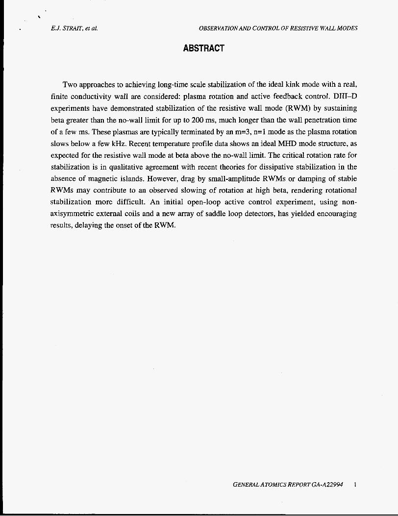
ABSTRACT
Two approaches to achieving long-time scale stabilization of the ideal kink mode with a real, finite conductivity wall are considered: plasma rotation and active feedback control. DIII-D experiments have demonstrated stabilization of the resistive wall mode (RWM) by sustaining beta greater than the no-wall limit for up to 200 ms, much longer than the wall penetration time of a few ms. These plasmas are typically terminated by an m=3, n=l mode as the plasma rotation slows below a few kHz. Recent temperature profile data shows an ideal MHD mode structure, as expected for the resistive wall mode at beta above the no-wall limit. The critical rotation rate for stabilization is in qualitative agreement with recent theories for dissipative stabilization in the absence of magnetic islands. However, drag by small-amplitude RWMs or damping of stable RWMs may contribute to an observed slowing of rotation at high beta, rendering rotational stabilization more difficult. An initial open-loop active control experiment, using non- axisymmetric external coils and a new array of saddle loop detectors, has yielded encouraging results, delaying the onset of the RWM.
GENERAL ATOMICS REPORT GA-A22994 1

E. .I. STRAIT, et al. OBSERVATION AND CONTROL OF RESISTIVE WALL MODES
1. INTRODUCTION
Stabilization of low-n kink modes by a conducting wall is crucial for high beta, steady state “advanced tokamak” scenarios. Operation at high beta allows a more compact and economical fusion plasma with a large fraction of bootstrap current. Good alignment of the bootstrap current with the equilibrium current density profile, important for minimizing the requirements on external current drive systems, is achieved with broad current density profiles and broad pressure profiles. Such broad profiles have a low beta limit in the absence of a wall, but strong coupling to a nearby conducting wall can improve the stability limit by as much as a factor of 2 or 3 [l-31.
Two approaches to achieving long-time scale stabilization with a real, finite conductivity wall are being considered: plasma rotation and active feedback control. Ideal MHD theory predicts that for a plasma which would be stabilized by an ideal wall, non-zero wall resistivity leads to an unstable “resistive wall mode” with a growth time on the order of the wall’s magnetic field penetration time zw and a real frequency o - z;’, and which is not stabilized by sub- Alfvenic plasma rotation [4]. However, more detailed theories show that the addition of dissipation in the plasma allows stabilization by sub-sonic plasma rotation [5,6]. Furthermore, external kink modes can drive islands in a resistive plasma, allowing stabilization by plasma rotation frequencies as low as SZ - z-,‘ [7,8].
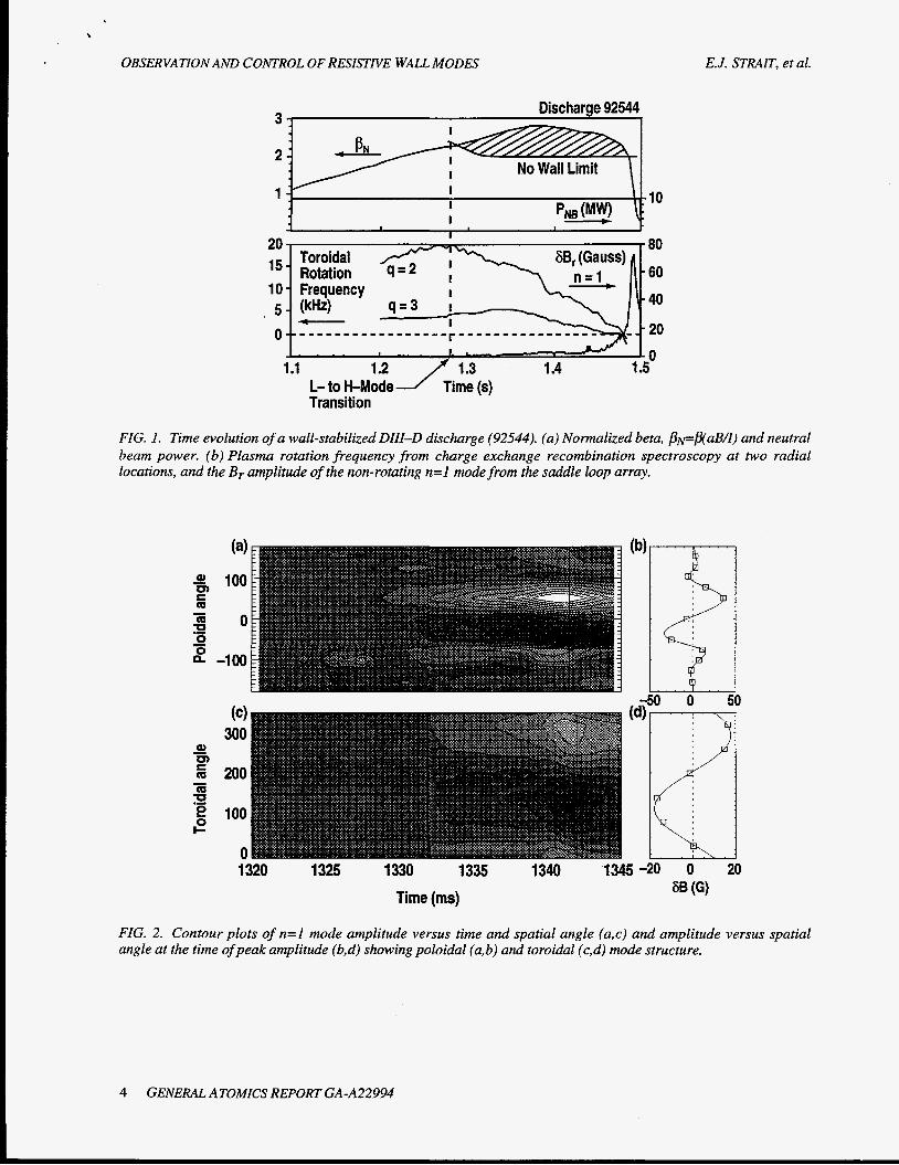
DIII-D experiments [9,10] confirm many of the important qualitative features of these more recent theories. In discharges with broad current density profiles, beta values reach up to 1.4 times the ideal n=l kink mode limit calculated without a wall, but remain within the stable range calculated with an ideal wall at the position of the DIII-D vacuum vessel. Beta greater than the no-wall limit has been sustained for up to 200 ms, much longer than the wall penetration time zw I 6 ms, which indicates that the resistive wall mode has been stabilized [Fig. l(a)]. As the rotation slows, these plasmas are typically terminated by an n=l mode which begins to grow as the plasma rotation at the q=3 surface decreases below 1-2 kHz, consistent with a loss of rotational stabilization [Fig. l(b)]. The mode typically has a growth time of 2-8 ms and a real frequency o ~TG’, as expected for a resistive wall mode. The poloidal structure of this nearly
stationary mode, as measured with saddle loops on the exterior surface of the vacuum vessel (Fig. 2), is predominantly m=3 and ballooning toward the large major radius side, consistent with an instability driven by the large current density and pressure gradient in the outer part of the plasma.
In many cases, temperature profiles measured with electron cyclotron emission show an ideal-like mode structure, without islands (Fig. 3), as expected for an ideal kink mode which has
GENERAL ATOMICS REPORT GA-A22994 3
OBSERVATION AND CONTROL OF RESISTIVE WALL MODES E. J. STRAIT, et al.
Discharge 92544 9
Transition
FIG. 1. Time evolution of a wall-stabilized DIII-D discharge (92544). (a) Normalized beta, /3pBaB/I) and neutral beam power. (b) Plasma rotation frequency from charge exchange recombination spectroscopy at two radial locations, and the Br amplitude of the non-rotating n=l mode from the saddle loop array.
(a 300
E 200 z 2 100 rp
0 1 320 1325 1330 1335 1340 1345 -20 0 20
Q) w - - rn
60 (GI Time (ms)
i FIG. 2. Contour plots of n=l mode amplitude versus time and spatial angle (a,c) and amplitude versus spatial angle at the time of peak amplitude (b,d) showing poloidal (a,b) and toroidal (c,d) mode structure.
4 GENERAL ATOMICS REPORT GA-A22994
E. J. STRAIT. et al. OBSERVATION AND CONTROL OF RESISTIVE WALL MODES
t 1.332 s I I 0 I 0.0 0.5 1 .o
P
, I .
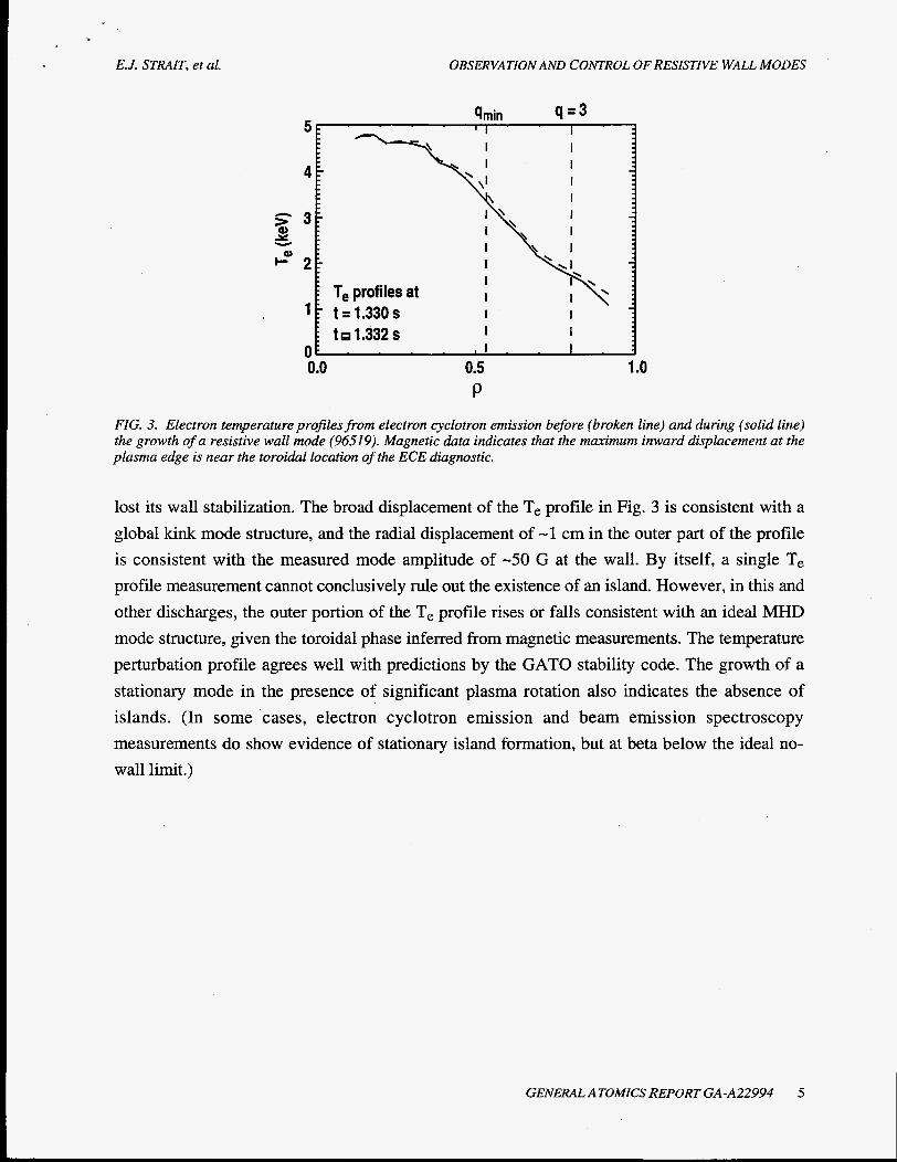
FIG. 3. Electron temperature profilesfrom electron cyclotron emission before (broken Line) and during (solid line) the growth of a resistive wall mode (96519). Magnetic data indicates that the maimurn inward displacement at the plasma edge is near the toroidal location of the ECE diagnostic.
lost its wall stabilization. The broad displacement of the Te profile in Fig. 3 is consistent with a global kink mode structure, and the radial displacement of -1 cm in the outer part of the profile is consistent with the measured mode amplitude of -50 G at the wall. By itself, a single Te profile measurement cannot conclusively rule out the existence of an island. However, in this and other discharges, the outer portion of the T, profile rises or falls consistent with an ideal MHD mode structure, given the toroidal phase inferred from magnetic measurements. The temperature perturbation profile agrees well with predictions by the GAT0 stability code. The growth of a stationary mode in the presence of significant plasma rotation also indicates the absence of islands. (In some cases, electron cyclotron emission and beam emission spectroscopy measurements do show evidence of stationary island formation, but at beta below the ideal no- wall limit.)
GENERAL ATOMICS REPORT GA-A22994 5
E.J. STRAIT. et al. OBSERVATION AND CONTROL OF RESISTIVE WALL MODES
2. ROTATIONAL STABILIZATION
Plasma rotation is one possible means for long time-scale stabilization by a resistive wall. Vacuum field measurements show that the DIII-D vacuum vessel wall penetration time for an imposed n=l radial magnetic field can be approximated by a 2-pole response with time constants of 7 ms and 1-3 ms. This agrees well with calculations using the SPARK 3D electromagnetic code which show that the time constant for the lowest n=l eigenmode of the DIII-D vacuum vessel is about 5.8 ms, followed by about 3 ms for the next eigenmodes. Stabilization for longer times in the experiment indicates that plasma rotation is important.
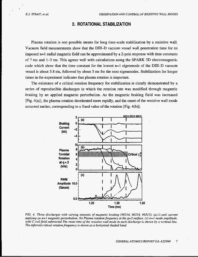
The existence of a critical rotation frequency for stabilization is clearly demonstrated by a series of reproducible discharges in which the rotation rate was modified through magnetic braking by an applied magnetic perturbation. As the magnetic braking field was increased [Fig. 4(a)], the plasma rotation decelerated more rapidly, and the onset of the resistive wall mode occurred earlier, corresponding to a fixed value of the rotation [Fig. 4(b)].
Braking Current (W
0
-2
-4
10 Plasma 8 Toroidal 6 Rotation 4
2 a tq=3 (kH4 *
RWM Amplitude (Gauss)
1 :25 1.30 1.35 Time (ms)
FIG. 4. Three discharges with varying amounts of magnetic braking (96514, 96518, 96515) . (a) C-coil current applying an n=l magnetic perturbation. (b) Plasma rotation frequency at the q=3 surface. (c) n=l mode amplitude, with C-coil field subtracted The onset time of the resistive wall mode in each discharge is shown by a vertical line. The inferred critical rotation frequency is shown as a horizontal shaded band.
GENERAL ATOMICS REPORT GA-A22994 7
OBSERVATION AND CONTROL OF RESISTIVE WALL MODES E.J. STRAIT, et al.
The experimental data allow us to distinguish at least qualitatively between predicted mechanisms for stabilization. The observed critical rotation frequency R=2xf- ~ 4 x 1 0 4 s-1 at the
q=3 surface disagrees with the predictions R- .rk113x1O2 s-1 of theories which include driven islands, and R - ZA-~ > 10 6 s-1 of ideal MHD theory. The agreement is somewhat closer with
predictions R - 0.05 .rxl - lo5 s-l of theories where the ideal mode is stabilized by dissipation which occurs through coupling to sound waves. The observed critical rotation speed is typically at least 10% of the ion acoustic speed, and thus may be consistent with coupling to sound waves.
We speculate that the much more rapid central rotation of R - l - 2 ~ 1 0 ~ s-l could also contribute to stabilization, and may account for the variation of the critical rotation frequency. Sound wave coupling and dissipation occur at resonant surfaces, while strong shaping and toroidicity couple poloidal modes so that all integer q surfaces are important in this global n=l instability. To date, the discharges which significantly exceed the no-wall beta limit have qmin 52, placing the q=2 surface in a region of strong rotation (Fig. 1, for example). The critical rotation frequency at the q=3 surface in these discharges is 1-2 kHz. Discharges with qfin>2 and hence no q=2 surface tend to have a resistive wall mode onset at lower beta and larger rotation, indicating that rotational stabilization is less effective. The discharges in Fig. 4, for example, have qminz2.3 and develop an RWM at pN-2.2 with a rotation frequency at the q=3 surface greater than 6 kHz.
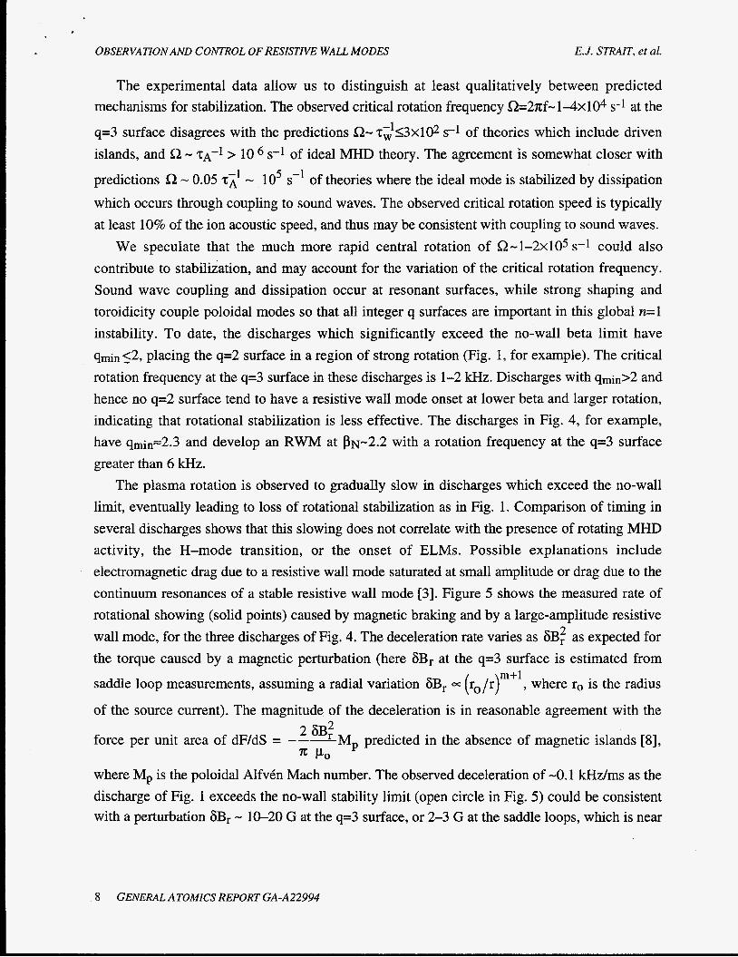
The plasma rotation is observed to gradually slow in discharges which exceed the no-wall limit, eventually leading to loss of rotational stabilization as in Fig. 1. Comparison of timing in several discharges shows that this slowing does not correlate with the presence of rotating MHD activity, the H-mode transition, or the onset of ELMS. Possible explanations include electromagnetic drag due to a resistive wall mode saturated at small amplitude or drag due to the continuum resonances of a stable resistive wall mode [3]. Figure 5 shows the measured rate of rotational showing (solid points) caused by magnetic braking and by a large-amplitude resistive wall mode, for the three discharges of Fig. 4. The deceleration rate varies as 6B: as expected for the torque caused by a magnetic perturbation (here 6Br at the q=3 surface is estimated from
saddle loop measurements, assuming a radial variation 6Br = ( ro /r)m+l, where r, is the radius
of the source current). The magnitude of the deceleration is in reasonable agreement with the
force per unit area of dF/dS = --- 6Br M, predicted in the absence of magnetic islands [8],
where Mp is the poloidal AlfvCn Mach number. The observed deceleration of -0.1 kHz/ms as the discharge of Fig. 1 exceeds the no-wall stability limit (open circle in Fig. 5) could be consistent with a perturbation 6Br - 10-20 G at the q=3 surface, or 2-3 G at the saddle loops, which is near
2
x Po
8 GENERAL ATOMICS REPORT GA-A22994
,
E, J. STRAIT, et al. OBSERVATION AND CONTROL OF RESISTIVE WALL MODES
the threshold for detection in this case. Further experimental and theoretical work is needed to determine whether this represents an inherent problem for rotational stabilization.
- H Measured
0 92544 inferred 2-
df / dt (kHdms) -
0 20 40 60 80 100 6B, (Gauss)
FIG. 5. Measured rate of rotational slowing versus 6B, at the q=3 s u ~ a c e due to applied magnetic braking and a large-amplitude resistive wall mode (solid circles, discharges 96514, 96518, 96515). Measured rate of slowing and inferred 6B, for a strongly wall-stabilized discharge (open circle, discharge 92544).
GENERAL ATOMICS REPORT GA-A22994 9

E. J. STRAIT, et al. OBSERVATION AND CONTROL OF RESISTIVE WALL MODES
3. ACTIVE CONTROL
The slow growth and rotation of the resistive wall mode should permit active feedback stabilization by non-axisymmetric coils outside the vacuum vessel, without the need for plasma rotation. Active suppression of resistive wall modes may also help to maintain rotation. Several approaches have been proposed, including the “smart shell” [ 1 1,121 where the feedback control is designed to maintain a net zero change in radial magnetic field at the resistive wall, and the “fake rotating shell” [ 131 in which a phase shift applied to the response mimics the effect of a rotating wall. These schemes will be tested in active control experiments which are planned for DIII-D, initially using the existing error field coil (C-coil). A set of six midplane saddle loops for mode detection have recently been installed, matched in geometry to the six toroidal segments of the C-coil.
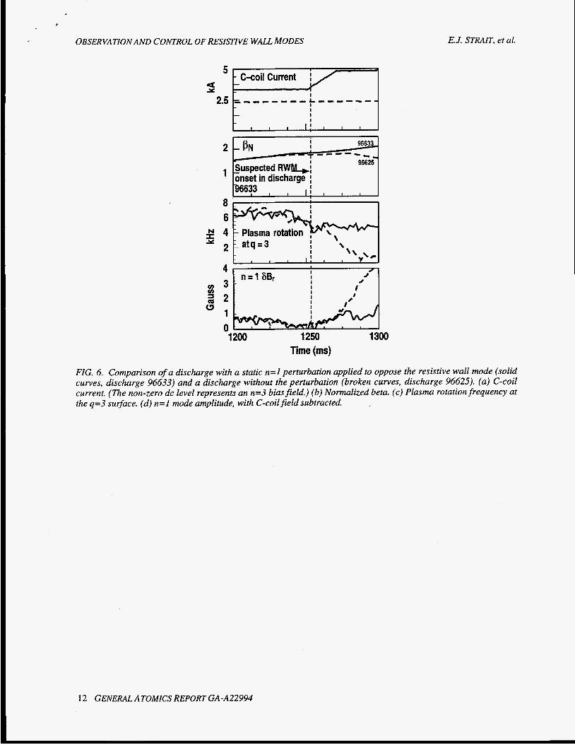
A preliminary experiment in open-loop control has been performed, with encouraging results for feedback control experiments. A series of discharges was established having a resistive wall mode at a reproducible onset time and spatial phase. Then the C-coil was programmed to produce a static n=l magnetic perturbation with a spatial phase opposing the mode, beginning at the anticipated onset time. (The lack of bipolar power supplies required this n=l perturbation to be superimposed on a constant n=3 bias field; other experiments established that this n=3 field has no detectable effect on plasma stability.) As seen in Fig. 6, in the stabilized discharge the electron temperature, beta, and plasma rotation hesitate at the anticipated onset time, then continue at constant or increasing values. In contrast, these parameters decrease rapidly in the comparison shot without the stabilizing n=l field. These results suggest that the resistive wall mode was stabilized by the opposing n=l field. Although complicated by the rapidly changing applied fields, analysis of the saddle loop data indicates that the instability was delayed by at least 20 ms.
Closed-loop feedback experiments in the near future will be aimed at comparing control algorithms and demonstrating improved stability. New bipolar power supplies to be procured in 1999 and 2000 will increase the power available for feedback stabilization. Numerical modeling with the VALEN 3D electromagnetic code [ 141 indicates that feedback stabilization using the existing 6-segment C-coil can produce a measurable (-15%-20%) increase in beta over the no- wall limit. Modeling also shows that an extension of the C-coil with additional segments above and below the midplane can double the margin over the no-wall stability limit by allowing better coupling to the helical mode structure. Experimental validation of the models with the existing midplane coil set will provide support for the design of the extended coil set.
GENERAL ATOMICS REPORT GA-A22994 11
OBSERVATION AND CONTROL OF RESISTIVE WALL MODES
I I I
E. J. STRAIT, et al.
I 4 I 3 I .#
4 , I n = 1 6 B r
3 - ! I I I I I I
I 2 ; 1 - 0-h 1200 1250 1300
Time (ms)
FIG. 6. Comparison of a discharge with a static n=l perturbation applied to oppose the resistive wall mode (solid curves, discharge 96633) and a discharge without the perturbation (broken curves, discharge 96625). (a) C-coil current. (The non-zero dc level represents an n=3 bias field.) (b) Normalized beta. (c) Plasma rotation frequency at the q=3 sulrface. (d) n=I mode amplitude, with C-coil field subtracted.
12 GENERAL ATOMICS REPORT GA-A22994

E.J. STRAIT, et al. OBSERVATION AND CONTROL OF RESISTIVE WALL MODES
4. SUMMARY
DJII-D experiments have shown that a resistive wall can stabilize a rotating plasma at beta values well above the ideal no-wall limit, for durations much longer than the resistive wall penetration time for n=l magnetic fields. The predicted resistive wall mode has been observed as the plasma rotation decreases below a critical value of a few kHz, and the ideal structure of the mode has been confirmed. The critical rotation frequency for stabilization may be consistent with theories which include dissipation by coupling to sound waves to provide stabilization in the absence of islands. Long-duration sustainment of wall-stabilized plasmas has been hindered by a slowing of rotation as beta exceeds the no-wall limit. We conjecture that the slowing may result from drag caused by a small-amplitude resistive wall mode or by continuum resonances of the stabilized resistive wall mode. Modeling predicts that feedback stabilization using non- axisymmetric coils can provide a significant increase over the no-wall beta limit. In a preliminary open-loop experiment, the onset of the resistive wall mode was postponed for several wall penetration times, an encouraging result for closed-loop feedback experiments.
GENERAL ATOMICS REPORT GA-A22994 13

E.J. STRAIT, et al. OBSERVATION AND CONTROL OF RESISTIVE WALL MODES
REFERENCES
[ 11 [2] [3]
MANICKAM, J., et al., Phys. Plasmas 1 1601 (1994). TAYLOR, T.S., et aL, Plasma Phys. Contr. Fusion 36 B229 (1994). TURNBULL, A.D., et al., Proc. 17th Int. Fusion Energy Conf. (International Atomic Energy Agency, Vienna, 1997) Vol. 11, p. 509. GIMBLETT, C.G., Nucl. Fusion 26 617 (1986). BONDESON,-A., and WARD, D.J., Phys. Rev. Lett. 72 2709 (1994); WARD, D.J., and BONDESON, A., Phys. Plasmas 2 1570 (1995).
[6] CHU, M.S., et al., Phys. Plasmas 2 2236 (1995). [7] FINN, J.M., Phys. Plasmas 2 198 (1995). [SI BOOZER, A.H., Phys. Plasmas 2 4521 (1995); Phys. Plasmas 3,4620 (1996). [9] TAYLOR, T.S., et al., Phys. Plasmas 2 2390 (1995). [lo] GAROFALO, A.M., et al., Proc. 1998 Euro. Conf. on Contr. Fusion and Plasma Physics,
Prague (to be published); General Atomics Report GA-A22985 (1998), to be submitted to Phys. Rev. Lett.
[ 1 11 BISHOP, C.M., Plasma Phys. Contr. Fusion 31 1179 (1989). [ 121 JENSEN, T.H. and FWZPATRICK, R., Phys. Plasmas 4 2997 (1997). [13] FITZPATRICK, R. and JENSEN, T.H., Phys. Plasmas 3 2641 (1996). [14] BIALEK, J., et al., Bull Am. Phys. SOC. 43 (1998), Division of Plasma Physics Conf.,
Abstract K6Q-29; BOOZER, A.M., Phys. Plasmas 5 3350 (1998).
[4] [5]
G E N E M ATOMICS REPORT GA-A22994 15
E.J. STRAIT. et al. OBSERVATION AND CONTROL OF RESISTIVE WALL MODES
ACKNOWLEDGMENT
Work supported by the U.S. Department of Energy under Contract Nos. DE-AC03- 89ER5 1 1 14, DE-AC02-76CH03073, DE-AC05-960R22464, W-7405-ENG-48 and Grant Nos. DE-FG03-97ER544 15, DE-FG02-89ER53297, and DE-FG02-92ER54 139.
GENERAL ATOMICS REPORT GA-A22994 17