Embed Size (px)
Citation preview
COL-5013-09
C H A P T E R4
Observing System Startup and Performing a Basic ConfigurationThis chapter describes how to start the system and perform a basic configuration for your Cisco 7200 VXR router. The chapter contains the following sections:
• Checking Conditions Prior to System Startup, page 4-1
• Starting the System and Observing Initial Conditions, page 4-2
• Configuring a Cisco 7200 VXR Router, page 4-3
• Performing Other Configuration Tasks, page 4-15
• Using show Commands to Check the Installation, page 4-16
• Replacing or Recovering a Lost Password, page 4-17
• Viewing Your System Configuration, page 4-20
• Performing Complex Configurations, page 4-22
Note For instructions about how to perform a basic configuration for a Cisco 7206VXR as a router shelf in a Cisco AS5800 Universal Access Server, refer to the Cisco AS5800 Universal Access Server publications that shipped with your access server.
This chapter guides you through a basic router configuration, which is sufficient for you to access your network. Complex configuration procedures are beyond the scope of this publication and can be found in the modular configuration and modular command reference publications in the Cisco IOS software configuration documentation set that corresponds to the software release installed on your Cisco hardware.
To configure a Cisco 7200 VXR router from a console, you need to connect a terminal to the router console port. Configuration requires access to the console port on the router I/O controller.
Checking Conditions Prior to System Startup Check the following conditions before you start your router:
• Each port adapter is inserted in its slot and its respective port adapter lever is in the locked position.
• The network services engine (NSE) or network processing engine (NPE) and the I/O controller, or the Port Adapter Jacket Card with and NPE-G1 and NPE-G2, are inserted in their slots and their captive installation screws are tightened.
4-1isco 7200 VXR Installation and Configuration Guide
Chapter 4 Observing System Startup and Performing a Basic ConfigurationStarting the System and Observing Initial Conditions
• All network interface cables are connected to the port adapters.
• A CompactFlash Disk, Flash Disk or Flash memory card is installed in its slot.
• Each power cable is connected and secured with the cable-retention clip.
• The console terminal is turned on.
You are now ready to start your router. Proceed to the section “Starting the System and Observing Initial Conditions.”
Starting the System and Observing Initial Conditions After installing your Cisco 7200 VXR router and connecting cables, start the router as follows:
Step 1 At the rear of the router, place the power switch on the power supply in the on (|) position. Repeat this if a second power supply is installed. The green OK LED on the power supply turns on.
Note When powering on or power off the router, wait 30 seconds before powering it on or powering it off again.
Step 2 Listen for the fans; you should immediately hear them operating.
Step 3 During the boot process, observe the system LEDs. The LEDs on most of the port adapters go on and off in irregular sequence. If the Port Adapter Jacket Card is installed, observe its LEDs. Some may go on, go out, and go on again for a short time. On the I/O controller, the IO power OK LED comes on immediately.
Step 4 Observe the initialization process. When the system boot is complete (a few seconds), the network processing engine or network services engine begins to initialize the port adapters and the I/O controller. During this initialization, the LEDs on each port adapter behave differently (most flash on and off).
The enabled LED on each port adapter goes on when initialization is completed, and the console screen displays a script and system banner similar to the following:
Cisco Internetwork Operating System Software IOS (tm) 7200 Software (C7200-JS-M), Released Version 12.0(19980705:021501)Copyright(c) 1986-1998 by cisco Systems, Inc.Compiled Tue 25-Aug-98 14:38 by xxxxxImage text-base: 0x600088C4, data-base: 0x60FA6000
Step 5 When you start up the router for the first time, the system automatically enters the setup facility, which determines which port adapters are installed and prompts you for configuration information for each one. On the console terminal, after the system displays the system banner and hardware configuration, you will see the following System Configuration Dialog prompt:
--- System Configuration Dialog ---
At any point you may enter a questions mark ‘?’ for help.Use ctrl-c to abort configuration dialog at any prompt.Default settings are in square brackets ‘[]’.
continue with configuration dialog? [yes]:
4-2Cisco 7200 VXR Installation and Configuration Guide
OL-5013-09
Chapter 4 Observing System Startup and Performing a Basic ConfigurationConfiguring a Cisco 7200 VXR Router
You have the option of proceeding with the setup facility to configure the interfaces, or exiting from setup and using configuration commands to configure global (system-wide) and interface-specific parameters. You do not have to configure the interfaces immediately; however, you cannot enable the interfaces or connect them to any networks until you have configured them.
Many of the port adapter LEDs do not go on until you have configured the interfaces. To verify correct operation of each interface, complete the first-time startup procedures and configuration, and then refer to the configuration note for each port adapter for LED descriptions and to check the status of the interfaces.
If the system does not complete each of the steps in the startup procedure, proceed to Chapter 5, “Troubleshooting the Installation” for troubleshooting recommendations and procedures.
Configuring a Cisco 7200 VXR RouterBefore configuring the router, determine whether or not you want to use a management tool such as Cisco Security Device Manager.
Cisco Security Device Manager (SDM), version 1.1, is an optional Java-based device-management tool that allows you to configure LAN interfaces, routing, Network Address Translation (NAT), firewalls, Virtual Private Networks (VPNs), and other features without knowledge of the Cisco command-line interface (CLI). You can configure features such as Access Control Lists (ACLs), routing protocols, and other options using SDMs advanced mode.
Note You will need to use CLI commands to configure several features that SDM does not support. SDM does not support the following features: WAN configuration, Gigabit Ethernet (GE) interfaces, AA client, EZ VPN server, QoS, SSHv2, DHCP server configuration options, and usability enhancements.
SDM is preinstalled on your router’s Flash Disk or CompactFlash Disk when it is ordered as part of a VPN bundle or as part of a 7xxx VPN bundle. If your router did not ship with SDM preinstalled, you can download a free copy from the Software Center at Cisco.com at http://www.cisco.com/kobayashi/sw-center/index.shtm. Because SDM uses a GUI, it requires that you access it from a PC using a supported web browser. Go to the Security Device Manager (SDM), Version 1.1 User Note for the 7xxx Routers for more information.
You can configure your Cisco 7200 VXR router using one of the procedures described in the following sections:
• Performing a Basic Configuration Using AutoInstall, page 4-4
• Performing a Basic Configuration Using the Setup Facility, page 4-4
• Configuring Port Adapter Interfaces, page 4-10
• Performing a Basic Configuration Using Global Configuration Mode, page 4-14
Follow the procedure that best fits the needs of your network configuration.
Note You need to acquire the correct network addresses from your system administrator or consult your network plan to determine correct addresses before you can complete the router configuration.
Before continuing the configuration process, check the current state of the router by entering the show version command. The show version command displays the release of Cisco IOS software that is available on the router.
4-3Cisco 7200 VXR Installation and Configuration Guide
OL-5013-09
Chapter 4 Observing System Startup and Performing a Basic ConfigurationConfiguring a Cisco 7200 VXR Router
Performing a Basic Configuration Using AutoInstall The AutoInstall process is designed to configure the Cisco 7200 VXR router automatically after connection to your WAN. For AutoInstall to work properly, a Transmission Control Protocol/Internet Protocol (TCP/IP) host on your network must be preconfigured to provide the required configuration files. The TCP/IP host may exist anywhere on the network as long as the following two conditions are maintained:
1. The host must be on the remote side of the router synchronous serial connection to the WAN.
2. User Datagram Protocol (UDP) broadcasts to and from the router and the TCP/IP host are enabled.
This functionality is coordinated by your system administrator at the site where the TCP/IP host is located. You should not use AutoInstall unless the required files are available on the TCP/IP host. Refer to the publications Configuration Fundamentals Configuration Guide and Configuration Fundamentals Command Reference for information about how AutoInstall works.
Complete the following steps to prepare your Cisco 7200 VXR router for the AutoInstall process:
Step 1 Attach the appropriate synchronous serial cable to synchronous serial interface 0 on the router.
Step 2 Turn the power switch on each power supply to the on (|) position. (This action turns on AC power to the router.)
Note After powering off the router, wait at least 30 seconds before powering it on again.
The router loads the operating system image from Flash memory. If the remote end of the WAN connection is connected and properly configured, the AutoInstall process begins.
Once the AutoInstall process is completed, use the copy running-config startup-config command to write the configuration data to the router’s nonvolatile random-access memory (NVRAM). Perform the following step to complete this task.
Step 3 At the # prompt, enter the following command:
Hostname# copy running-config startup-config
Note Completing Step 3 saves the configuration settings that the AutoInstall process created to NVRAM. If you fail to do this, your configuration will be lost the next time you reload the router.
Performing a Basic Configuration Using the Setup Facility If you do not plan to use AutoInstall, do not connect the router’s serial (WAN) cable to the channel service unit/data service unit (CSU/DSU). If the WAN cable is not connected, the router boots from Flash memory and goes automatically into the setup facility.
Note You can run the setup facility any time you are at the enable prompt (#) by entering the setup command.
4-4Cisco 7200 VXR Installation and Configuration Guide
OL-5013-09
Chapter 4 Observing System Startup and Performing a Basic ConfigurationConfiguring a Cisco 7200 VXR Router
If the serial (WAN) cable is connected to the CSU/DSU and the router does not have a configuration stored in NVRAM, the router attempts to run AutoInstall at startup. The router may take several minutes to determine that AutoInstall is not set up to a remote TCP/IP host. Once the router determines that AutoInstall is not configured, it defaults to the setup facility.
Configuring Global Parameters
When you first start the setup program, you must configure the global parameters. These parameters are used for controlling system-wide settings. Complete the following steps to enter the global parameters:
Step 1 Connect a console terminal to the console port on the I/O controller, NPE-G1, or NPE-G2, and then boot the router.
The system boots from Flash memory. The following information appears after about 30 seconds. When you see this information, you have successfully booted your router:
Restricted Rights Legend Use, duplication, or disclosure by the Government issubject to restrictions as set forth in subparagraph(c) of the Commercial Computer Software - RestrictedRights clause at FAR sec. 52.227-19 and subparagraph(c) (1) (ii) of the Rights in Technical Data and ComputerSoftware clause at DFARS sec. 252.227-7013.
cisco Systems, Inc. 170 West Tasman Drive San Jose, California 95134-1706
Cisco Internetwork Operating System Software IOS (tm) 7200 Software (C7200-JS-M), Released Version 12.0(19980705:021501)Copyright(c) 1986-1998 by cisco Systems, Inc.Compiled Thu 15-Oct-98 02:20 by xxxxxImage text-base: 0x600088C4, data-base: 0x60FA6000
cisco 7206VXR (NPE300) processor with 61440K/20480K bytes of memory.R7000 CPU at 262Mhz, Implementation 39, Rev 1.0, 256KB L2, 2048KB L3 CacheSix slot VXR midplane, Version 2.0
Last reset from power-onBridging software.X.25 software, Version 3.0.0.SuperLAT software (copyright 1990 by Meridian Technology Corp).TN3270 Emulation software.8 Ethernet/IEEE 802.3 interface(s)3 FastEthernet/IEEE 802.3 interface(s)125K bytes of non-volatile configuration memory.
20480K bytes of Flash PCMCIA card at slot 0 (Sector size 128K).8192K bytes of Flash PCMCIA card at slot 1 (Sector size 128K).4096K bytes of Flash internal SIMM (Sector size 256K).!! Press RETURN to get started!
4-5Cisco 7200 VXR Installation and Configuration Guide
OL-5013-09
Chapter 4 Observing System Startup and Performing a Basic ConfigurationConfiguring a Cisco 7200 VXR Router
The first two sections of the configuration script (the banner and the installed hardware) appear only at initial system startup. On subsequent uses of the setup facility, the script begins with a System Configuration Dialog as shown in the following example.
--- System Configuration Dialog --- At any point you may enter a question mark '?' for help.Use ctrl-c to abort configuration dialog at any prompt.Default settings are in square brackets '[]'.
Step 2 When asked if you want to enter the initial configuration dialog and see the current interface summary, enter yes or press Return:
Would you like to enter the initial configuration dialog? [yes]:
First, would you like to see the current interface summary? [yes]:
In the following example, the summary shows a Cisco 7200 VXR router at first-time startup; that is, nothing is configured.
Any interface listed with OK? value "NO" does not have a valid configuration Interface IP-Address OK? Method Status ProtocolATM1/0 unassigned NO unset down downFastEthernet2/0 unassigned NO unset down down
Step 3 Choose which protocols to support on your interfaces. For Internet Protocol (IP)-only installations, you can accept the default values for most of the questions. A typical configuration using IP, IPX, and AppleTalk follows and continues through Step 8:
Configuring global parameters:
Enter host name [Router]:
Step 4 Enter enable secret, enable, and virtual terminal passwords:
The enable secret password is a one-way cryptographic secret password used instead of the enable password when it exists.
Enter enable secret: barney
The enable password is used when there is no enable secretpassword and when using older software and some boot images.
Enter enable password: betty
Enter virtual terminal password: fred
Step 5 The Simple Network Management Protocol (SNMP) is the most widely supported open standard for network management. It provides a means to access and set configuration and run-time parameters of routers and communication servers. SNMP defines a set of functions that can be used to monitor and control network elements.
Enter yes or press Return to accept SNMP management; enter no to refuse it:
Configure SNMP Network Management? [yes]: Community string [public]:
4-6Cisco 7200 VXR Installation and Configuration Guide
OL-5013-09
Chapter 4 Observing System Startup and Performing a Basic ConfigurationConfiguring a Cisco 7200 VXR Router
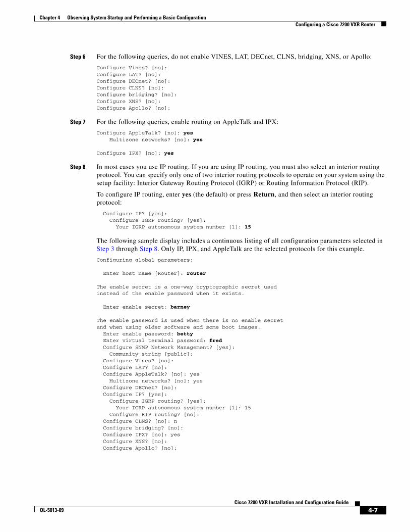
Step 6 For the following queries, do not enable VINES, LAT, DECnet, CLNS, bridging, XNS, or Apollo:
Configure Vines? [no]:Configure LAT? [no]:Configure DECnet? [no]:Configure CLNS? [no]:Configure bridging? [no]:Configure XNS? [no]:Configure Apollo? [no]:
Step 7 For the following queries, enable routing on AppleTalk and IPX:
Configure AppleTalk? [no]: yes Multizone networks? [no]: yes
Configure IPX? [no]: yes
Step 8 In most cases you use IP routing. If you are using IP routing, you must also select an interior routing protocol. You can specify only one of two interior routing protocols to operate on your system using the setup facility: Interior Gateway Routing Protocol (IGRP) or Routing Information Protocol (RIP).
To configure IP routing, enter yes (the default) or press Return, and then select an interior routing protocol:
Configure IP? [yes]: Configure IGRP routing? [yes]: Your IGRP autonomous system number [1]: 15
The following sample display includes a continuous listing of all configuration parameters selected in Step 3 through Step 8. Only IP, IPX, and AppleTalk are the selected protocols for this example.
Configuring global parameters:
Enter host name [Router]: router
The enable secret is a one-way cryptographic secret usedinstead of the enable password when it exists.
Enter enable secret: barney
The enable password is used when there is no enable secretand when using older software and some boot images.
Enter enable password: bettyEnter virtual terminal password: fredConfigure SNMP Network Management? [yes]:
Community string [public]:Configure Vines? [no]:
Configure LAT? [no]: Configure AppleTalk? [no]: yes
Multizone networks? [no]: yesConfigure DECnet? [no]: Configure IP? [yes]:
Configure IGRP routing? [yes]: Your IGRP autonomous system number [1]: 15
Configure RIP routing? [no]:Configure CLNS? [no]: n
Configure bridging? [no]: Configure IPX? [no]: yes Configure XNS? [no]: Configure Apollo? [no]:
4-7Cisco 7200 VXR Installation and Configuration Guide
OL-5013-09
Chapter 4 Observing System Startup and Performing a Basic ConfigurationConfiguring a Cisco 7200 VXR Router
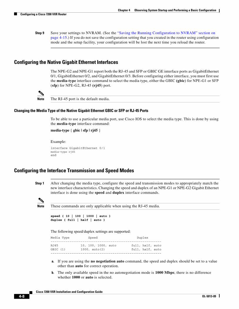
Step 9 Save your settings to NVRAM. (See the “Saving the Running Configuration to NVRAM” section on page 4-15.) If you do not save the configuration setting that you created in the router using configuration mode and the setup facility, your configuration will be lost the next time you reload the router.
Configuring the Native Gigabit Ethernet Interfaces
The NPE-G2 and NPE-G1 report both the RJ-45 and SFP or GBIC GE interface ports as GigabitEthernet 0/1, GigabitEthernet 0/2, and GigabitEthernet 0/3. Before configuring either interface, you must first use the media-type interface command to select the media type, either the GBIC (gbic) for NPE-G1 or SFP (sfp) for NPE-G2, RJ-45 (rj45) port.
Note The RJ-45 port is the default media.
Changing the Media Type of the Native Gigabit Ethernet GBIC or SFP or RJ-45 Ports
To be able to use a particular media port, use Cisco IOS to select the media type. This is done by using the media-type interface command:
media-type { gbic | sfp | rj45 }
Example:
interface GigabitEthernet 0/1media-type rj45end
Configuring the Interface Transmission and Speed Modes
Step 1 After changing the media type, configure the speed and transmission modes to appropriately match the new interface characteristics. Changing the speed and duplex of an NPE-G1 or NPE-G2 Gigabit Ethernet interface is done using the speed and duplex interface commands.
Note These commands are only applicable when using the RJ-45 media.
speed { 10 | 100 | 1000 | auto }duplex { full | half | auto }
The following speed/duplex settings are supported: Media Type Speed Duplex-----------------------------------------------------------RJ45 10, 100, 1000, auto full, half, autoGBIC (1) 1000, auto(2) full, half, auto -----------------------------------------------------------
a. If you are using the no negotiation auto command, the speed and duplex should be set to a value other than auto for correct operation.
b. The only available speed in the no autonegotiation mode is 1000 Mbps; there is no difference whether 1000 or auto is selected.
4-8Cisco 7200 VXR Installation and Configuration Guide
OL-5013-09
Chapter 4 Observing System Startup and Performing a Basic ConfigurationConfiguring a Cisco 7200 VXR Router
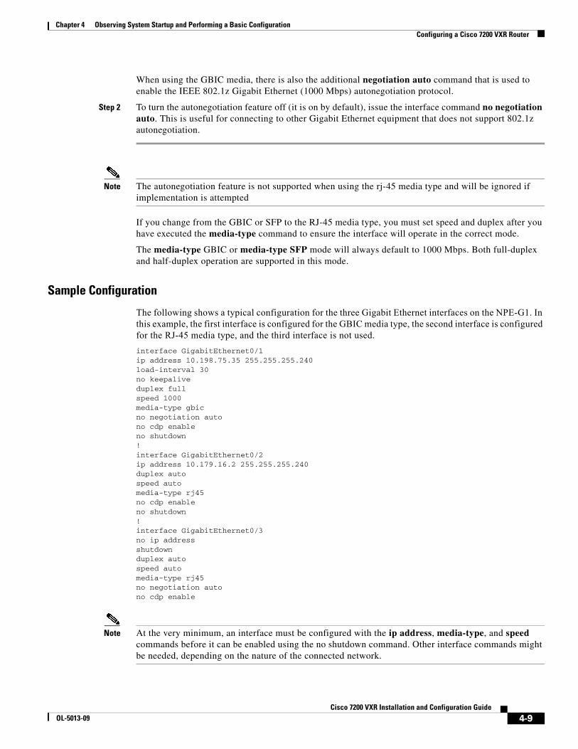
When using the GBIC media, there is also the additional negotiation auto command that is used to enable the IEEE 802.1z Gigabit Ethernet (1000 Mbps) autonegotiation protocol.
Step 2 To turn the autonegotiation feature off (it is on by default), issue the interface command no negotiation auto. This is useful for connecting to other Gigabit Ethernet equipment that does not support 802.1z autonegotiation.
Note The autonegotiation feature is not supported when using the rj-45 media type and will be ignored if implementation is attempted
If you change from the GBIC or SFP to the RJ-45 media type, you must set speed and duplex after you have executed the media-type command to ensure the interface will operate in the correct mode.
The media-type GBIC or media-type SFP mode will always default to 1000 Mbps. Both full-duplex and half-duplex operation are supported in this mode.
Sample Configuration
The following shows a typical configuration for the three Gigabit Ethernet interfaces on the NPE-G1. In this example, the first interface is configured for the GBIC media type, the second interface is configured for the RJ-45 media type, and the third interface is not used. interface GigabitEthernet0/1 ip address 10.198.75.35 255.255.255.240 load-interval 30 no keepalive duplex full speed 1000 media-type gbic no negotiation auto no cdp enableno shutdown!interface GigabitEthernet0/2 ip address 10.179.16.2 255.255.255.240duplex auto speed auto media-type rj45 no cdp enableno shutdown ! interface GigabitEthernet0/3no ip address shutdown duplex auto speed automedia-type rj45 no negotiation auto no cdp enable
Note At the very minimum, an interface must be configured with the ip address, media-type, and speed commands before it can be enabled using the no shutdown command. Other interface commands might be needed, depending on the nature of the connected network.
4-9Cisco 7200 VXR Installation and Configuration Guide
OL-5013-09
Chapter 4 Observing System Startup and Performing a Basic ConfigurationConfiguring a Cisco 7200 VXR Router
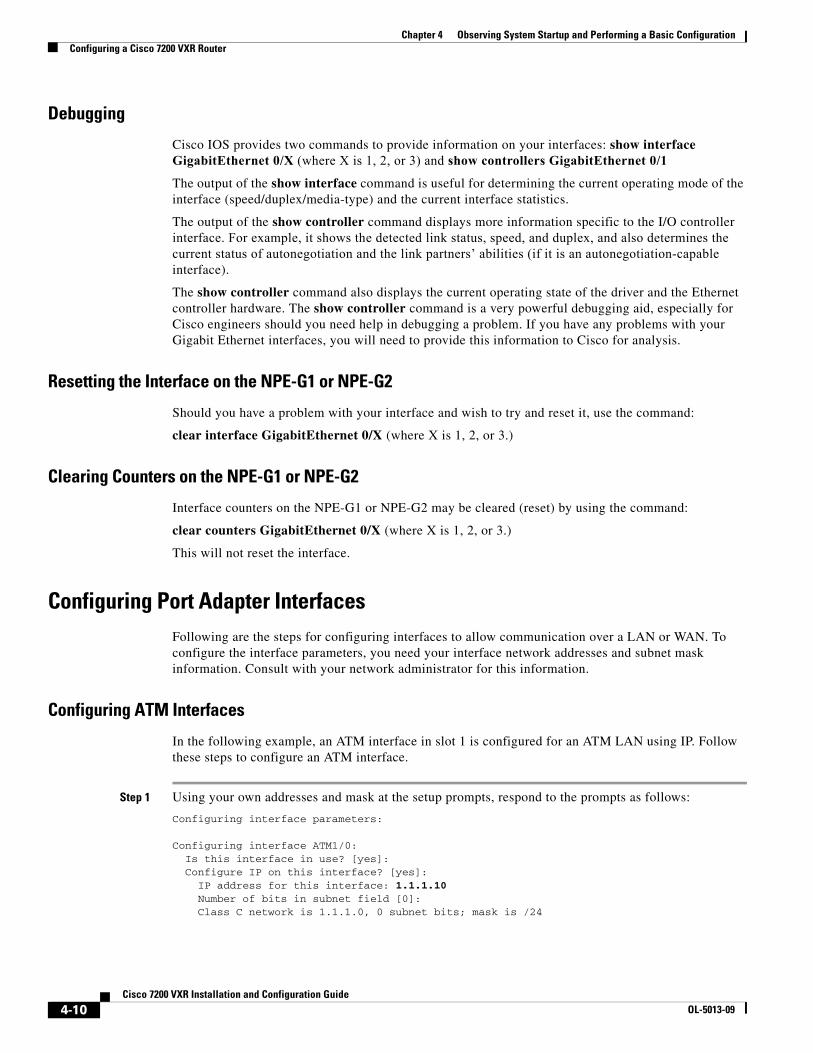
Debugging
Cisco IOS provides two commands to provide information on your interfaces: show interface GigabitEthernet 0/X (where X is 1, 2, or 3) and show controllers GigabitEthernet 0/1
The output of the show interface command is useful for determining the current operating mode of the interface (speed/duplex/media-type) and the current interface statistics.
The output of the show controller command displays more information specific to the I/O controller interface. For example, it shows the detected link status, speed, and duplex, and also determines the current status of autonegotiation and the link partners’ abilities (if it is an autonegotiation-capable interface).
The show controller command also displays the current operating state of the driver and the Ethernet controller hardware. The show controller command is a very powerful debugging aid, especially for Cisco engineers should you need help in debugging a problem. If you have any problems with your Gigabit Ethernet interfaces, you will need to provide this information to Cisco for analysis.
Resetting the Interface on the NPE-G1 or NPE-G2
Should you have a problem with your interface and wish to try and reset it, use the command:
clear interface GigabitEthernet 0/X (where X is 1, 2, or 3.)
Clearing Counters on the NPE-G1 or NPE-G2
Interface counters on the NPE-G1 or NPE-G2 may be cleared (reset) by using the command:
clear counters GigabitEthernet 0/X (where X is 1, 2, or 3.)
This will not reset the interface.
Configuring Port Adapter Interfaces Following are the steps for configuring interfaces to allow communication over a LAN or WAN. To configure the interface parameters, you need your interface network addresses and subnet mask information. Consult with your network administrator for this information.
Configuring ATM Interfaces
In the following example, an ATM interface in slot 1 is configured for an ATM LAN using IP. Follow these steps to configure an ATM interface.
Step 1 Using your own addresses and mask at the setup prompts, respond to the prompts as follows:
Configuring interface parameters:
Configuring interface ATM1/0: Is this interface in use? [yes]: Configure IP on this interface? [yes]: IP address for this interface: 1.1.1.10 Number of bits in subnet field [0]: Class C network is 1.1.1.0, 0 subnet bits; mask is /24
4-10Cisco 7200 VXR Installation and Configuration Guide
OL-5013-09
Chapter 4 Observing System Startup and Performing a Basic ConfigurationConfiguring a Cisco 7200 VXR Router
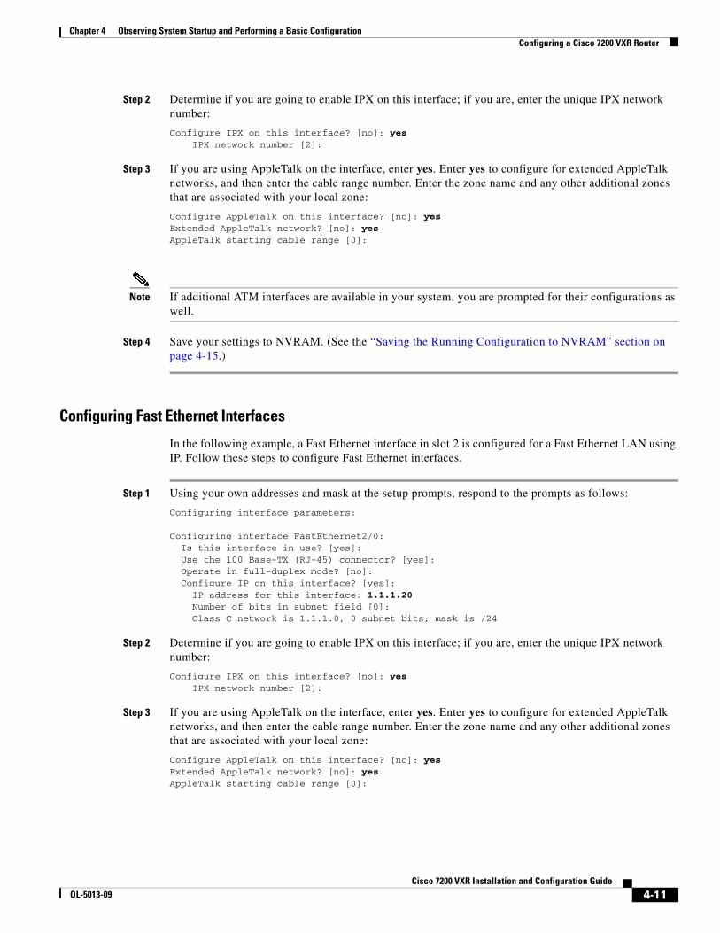
Step 2 Determine if you are going to enable IPX on this interface; if you are, enter the unique IPX network number:
Configure IPX on this interface? [no]: yes IPX network number [2]:
Step 3 If you are using AppleTalk on the interface, enter yes. Enter yes to configure for extended AppleTalk networks, and then enter the cable range number. Enter the zone name and any other additional zones that are associated with your local zone:
Configure AppleTalk on this interface? [no]: yesExtended AppleTalk network? [no]: yesAppleTalk starting cable range [0]:
Note If additional ATM interfaces are available in your system, you are prompted for their configurations as well.
Step 4 Save your settings to NVRAM. (See the “Saving the Running Configuration to NVRAM” section on page 4-15.)
Configuring Fast Ethernet Interfaces
In the following example, a Fast Ethernet interface in slot 2 is configured for a Fast Ethernet LAN using IP. Follow these steps to configure Fast Ethernet interfaces.
Step 1 Using your own addresses and mask at the setup prompts, respond to the prompts as follows:
Configuring interface parameters:
Configuring interface FastEthernet2/0: Is this interface in use? [yes]: Use the 100 Base-TX (RJ-45) connector? [yes]: Operate in full-duplex mode? [no]: Configure IP on this interface? [yes]: IP address for this interface: 1.1.1.20 Number of bits in subnet field [0]: Class C network is 1.1.1.0, 0 subnet bits; mask is /24
Step 2 Determine if you are going to enable IPX on this interface; if you are, enter the unique IPX network number:
Configure IPX on this interface? [no]: yes IPX network number [2]:
Step 3 If you are using AppleTalk on the interface, enter yes. Enter yes to configure for extended AppleTalk networks, and then enter the cable range number. Enter the zone name and any other additional zones that are associated with your local zone:
Configure AppleTalk on this interface? [no]: yesExtended AppleTalk network? [no]: yesAppleTalk starting cable range [0]:
4-11Cisco 7200 VXR Installation and Configuration Guide
OL-5013-09
Chapter 4 Observing System Startup and Performing a Basic ConfigurationConfiguring a Cisco 7200 VXR Router
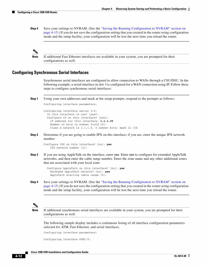
Step 4 Save your settings to NVRAM. (See the “Saving the Running Configuration to NVRAM” section on page 4-15.) If you do not save the configuration setting that you created in the router using configuration mode and the setup facility, your configuration will be lost the next time you reload the router.
Note If additional Fast Ethernet interfaces are available in your system, you are prompted for their configurations as well.
Configuring Synchronous Serial Interfaces
Synchronous serial interfaces are configured to allow connection to WANs through a CSU/DSU. In the following example, a serial interface in slot 3 is configured for a WAN connection using IP. Follow these steps to configure synchronous serial interfaces:
Step 1 Using your own addresses and mask at the setup prompts, respond to the prompts as follows:
Configuring interface parameters:
Configuring interface serial 3/0: Is this interface in use? [yes]: Configure IP on this interface? [yes]: IP address for this interface: 1.1.1.30 Number of bits in subnet field [0]: Class A network is 1.1.1.0, 0 subnet bits; mask is /24
Step 2 Determine if you are going to enable IPX on this interface; if you are, enter the unique IPX network number:
Configure IPX on this interface? [no]: yes IPX network number [2]:
Step 3 If you are using AppleTalk on the interface, enter yes. Enter yes to configure for extended AppleTalk networks, and then enter the cable range number. Enter the zone name and any other additional zones that are associated with your local zone:
Configure AppleTalk on this interface? [no]: yesExtended AppleTalk network? [no]: yesAppleTalk starting cable range [0]:
Step 4 Save your settings to NVRAM. (See the “Saving the Running Configuration to NVRAM” section on page 4-15.) If you do not save the configuration setting that you created in the router using configuration mode and the setup facility, your configuration will be lost the next time you reload the router.
Note If additional synchronous serial interfaces are available in your system, you are prompted for their configurations as well.
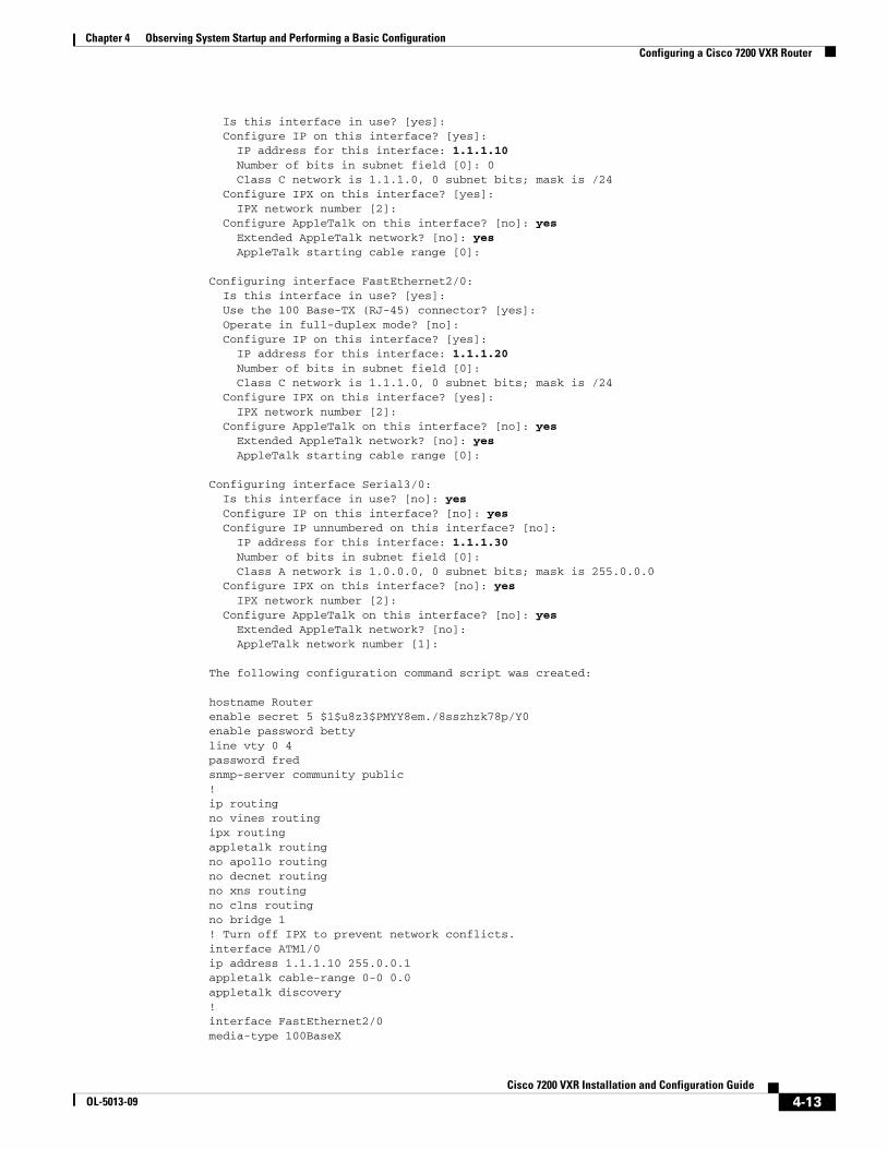
The following sample display includes a continuous listing of all interface configuration parameters selected for ATM, Fast Ethernet, and serial interfaces.
Configuring interface parameters:
Configuring interface ATM1/0:
4-12Cisco 7200 VXR Installation and Configuration Guide
OL-5013-09
Chapter 4 Observing System Startup and Performing a Basic ConfigurationConfiguring a Cisco 7200 VXR Router
Is this interface in use? [yes]: Configure IP on this interface? [yes]:
IP address for this interface: 1.1.1.10Number of bits in subnet field [0]: 0Class C network is 1.1.1.0, 0 subnet bits; mask is /24
Configure IPX on this interface? [yes]:IPX network number [2]:
Configure AppleTalk on this interface? [no]: yesExtended AppleTalk network? [no]: yesAppleTalk starting cable range [0]:
Configuring interface FastEthernet2/0:Is this interface in use? [yes]: Use the 100 Base-TX (RJ-45) connector? [yes]:Operate in full-duplex mode? [no]:Configure IP on this interface? [yes]:
IP address for this interface: 1.1.1.20 Number of bits in subnet field [0]: Class C network is 1.1.1.0, 0 subnet bits; mask is /24
Configure IPX on this interface? [yes]:IPX network number [2]:
Configure AppleTalk on this interface? [no]: yesExtended AppleTalk network? [no]: yesAppleTalk starting cable range [0]:
Configuring interface Serial3/0:Is this interface in use? [no]: yesConfigure IP on this interface? [no]: yesConfigure IP unnumbered on this interface? [no]:
IP address for this interface: 1.1.1.30Number of bits in subnet field [0]:Class A network is 1.0.0.0, 0 subnet bits; mask is 255.0.0.0
Configure IPX on this interface? [no]: yesIPX network number [2]:
Configure AppleTalk on this interface? [no]: yesExtended AppleTalk network? [no]:AppleTalk network number [1]:
The following configuration command script was created:
hostname Routerenable secret 5 $1$u8z3$PMYY8em./8sszhzk78p/Y0enable password bettyline vty 0 4password fredsnmp-server community public!ip routingno vines routingipx routingappletalk routingno apollo routingno decnet routingno xns routingno clns routingno bridge 1! Turn off IPX to prevent network conflicts.interface ATM1/0ip address 1.1.1.10 255.0.0.1appletalk cable-range 0-0 0.0appletalk discovery!interface FastEthernet2/0media-type 100BaseX
4-13Cisco 7200 VXR Installation and Configuration Guide
OL-5013-09
Chapter 4 Observing System Startup and Performing a Basic ConfigurationConfiguring a Cisco 7200 VXR Router
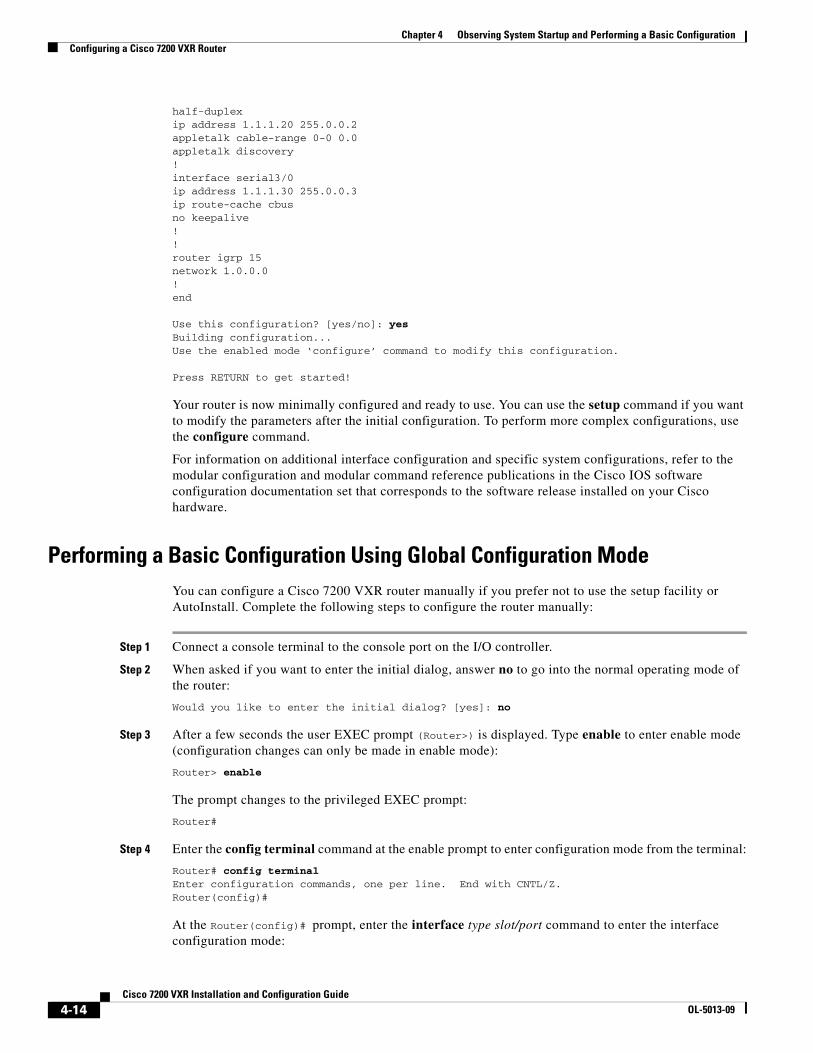
half-duplexip address 1.1.1.20 255.0.0.2appletalk cable-range 0-0 0.0appletalk discovery!interface serial3/0ip address 1.1.1.30 255.0.0.3ip route-cache cbusno keepalive!!router igrp 15network 1.0.0.0!end
Use this configuration? [yes/no]: yesBuilding configuration...Use the enabled mode ‘configure’ command to modify this configuration.
Press RETURN to get started!
Your router is now minimally configured and ready to use. You can use the setup command if you want to modify the parameters after the initial configuration. To perform more complex configurations, use the configure command.
For information on additional interface configuration and specific system configurations, refer to the modular configuration and modular command reference publications in the Cisco IOS software configuration documentation set that corresponds to the software release installed on your Cisco hardware.
Performing a Basic Configuration Using Global Configuration Mode You can configure a Cisco 7200 VXR router manually if you prefer not to use the setup facility or AutoInstall. Complete the following steps to configure the router manually:
Step 1 Connect a console terminal to the console port on the I/O controller.
Step 2 When asked if you want to enter the initial dialog, answer no to go into the normal operating mode of the router:
Would you like to enter the initial dialog? [yes]: no
Step 3 After a few seconds the user EXEC prompt (Router>) is displayed. Type enable to enter enable mode (configuration changes can only be made in enable mode):
Router> enable
The prompt changes to the privileged EXEC prompt:
Router#
Step 4 Enter the config terminal command at the enable prompt to enter configuration mode from the terminal:
Router# config terminalEnter configuration commands, one per line. End with CNTL/Z.Router(config)#
At the Router(config)# prompt, enter the interface type slot/port command to enter the interface configuration mode:
4-14Cisco 7200 VXR Installation and Configuration Guide
OL-5013-09
Chapter 4 Observing System Startup and Performing a Basic ConfigurationPerforming Other Configuration Tasks
Router(config)# interface serial slot/portRouter(config-int)#
In either configuration mode, you can now enter any changes to the configuration. Press Ctrl-Z (hold down the Control key while you press Z) or enter end to exit configuration mode and return to the EXEC command interpreter.
Step 5 Save your settings to NVRAM. (See the “Saving the Running Configuration to NVRAM” section on page 4-15.) If you do not save the configuration setting that you created in the router using configuration mode and the setup facility, your configuration will be lost the next time you reload the router.
Your router is now minimally configured and will boot with the configuration you have entered. To see a list of the configuration commands available to you, enter ? at the prompt or press the Help key while in configuration mode.
Saving the Running Configuration to NVRAM To store the configuration or changes to your startup configuration in NVRAM, enter the copy running-config startup-config command at the Router# prompt:
Router# copy running-config startup-config
Using this command saves the configuration settings that you created in the router using configuration mode and the setup facility. If you fail to do this, your configuration will be lost the next time you reload the router.
Checking the Running Configuration SettingsTo check the value of the settings you have entered, enter the show running-config command at the Router# prompt:
Router# show running-config
To review changes you make to the configuration, use the EXEC mode show startup-config command to display the information stored in NVRAM.
Performing Other Configuration Tasks To make advanced configuration changes after you establish the basic startup configuration for your router, refer to the modular configuration and modular command reference publications in the Cisco IOS software configuration documentation set that corresponds to the software release installed on your Cisco hardware. These publications contain additional information on using the configure command.
The configuration publications also provide information about the following tasks:
• Understanding and working with the user interface on your router
• Booting and rebooting the router
• Setting the configuration register
4-15Cisco 7200 VXR Installation and Configuration Guide
OL-5013-09
Chapter 4 Observing System Startup and Performing a Basic ConfigurationUsing show Commands to Check the Installation
• Loading configuration files or system images using remote copy protocol (rcp) or Trivial File Transfer Protocol (TFTP)
• Reloading the operating system
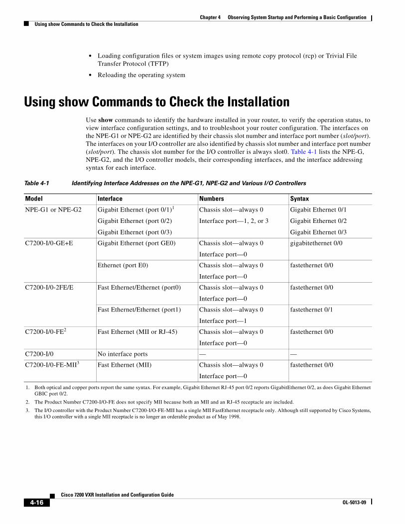
Using show Commands to Check the InstallationUse show commands to identify the hardware installed in your router, to verify the operation status, to view interface configuration settings, and to troubleshoot your router configuration. The interfaces on the NPE-G1 or NPE-G2 are identified by their chassis slot number and interface port number (slot/port). The interfaces on your I/O controller are also identified by chassis slot number and interface port number (slot/port). The chassis slot number for the I/O controller is always slot0. Table 4-1 lists the NPE-G, NPE-G2, and the I/O controller models, their corresponding interfaces, and the interface addressing syntax for each interface.
Table 4-1 Identifying Interface Addresses on the NPE-G1, NPE-G2 and Various I/O Controllers
Model Interface Numbers Syntax
NPE-G1 or NPE-G2 Gigabit Ethernet (port 0/1)1
Gigabit Ethernet (port 0/2)
Gigabit Ethernet (port 0/3)
1. Both optical and copper ports report the same syntax. For example, Gigabit Ethernet RJ-45 port 0/2 reports GigabitEthernet 0/2, as does Gigabit Ethernet GBIC port 0/2.
Chassis slot—always 0
Interface port—1, 2, or 3
Gigabit Ethernet 0/1
Gigabit Ethernet 0/2
Gigabit Ethernet 0/3
C7200-I/0-GE+E Gigabit Ethernet (port GE0) Chassis slot—always 0
Interface port—0
gigabitethernet 0/0
Ethernet (port E0) Chassis slot—always 0
Interface port—0
fastethernet 0/0
C7200-I/0-2FE/E Fast Ethernet/Ethernet (port0) Chassis slot—always 0
Interface port—0
fastethernet 0/0
Fast Ethernet/Ethernet (port1) Chassis slot—always 0
Interface port—1
fastethernet 0/1
C7200-I/0-FE2
2. The Product Number C7200-I/O-FE does not specify MII because both an MII and an RJ-45 receptacle are included.
Fast Ethernet (MII or RJ-45) Chassis slot—always 0
Interface port—0
fastethernet 0/0
C7200-I/0 No interface ports — —
C7200-I/0-FE-MII3
3. The I/O controller with the Product Number C7200-I/O-FE-MII has a single MII FastEthernet receptacle only. Although still supported by Cisco Systems, this I/O controller with a single MII receptacle is no longer an orderable product as of May 1998.
Fast Ethernet (MII) Chassis slot—always 0
Interface port—0
fastethernet 0/0
4-16Cisco 7200 VXR Installation and Configuration Guide
OL-5013-09
Chapter 4 Observing System Startup and Performing a Basic ConfigurationReplacing or Recovering a Lost Password
Replacing or Recovering a Lost PasswordThis section describes how to recover a lost enable or console login password, and how to replace a lost enable secret password on your Cisco 7200 VXR router.
Note It is possible to recover the enable or console login password. The enable secret password is encrypted, however, and must be replaced with a new enable secret password.
Overview of the Password Recovery ProcedureFollowing is an overview of the steps in the password recovery procedure:
Step 1 If you can log in to the router, enter the show version command to determine the existing configuration register value.
Step 2 Press the Break key to get to the bootstrap program prompt (ROM monitor). You might need to reload the system image by power cycling the router.
Step 3 Change the configuration register so the following functions are enabled:
a. Break
b. Ignore startup configuration
c. Boot from Flash memory
Note The key to recovering a lost password is to set the configuration register bit 6 (0x0040) so that the startup configuration (usually in NVRAM) is ignored. This allows you to log in without using a password and to display the startup configuration passwords.
Step 4 Power cycle the router by turning power off and then back on. However, after powering off the router, wait at least 30 seconds before powering it on again.
Step 5 Log in to the router and enter the privileged EXEC mode.
Step 6 Enter the show startup-config command to display the passwords.
Step 7 Recover or replace the displayed passwords.
Step 8 Change the configuration register back to its original setting.
Note To recover a lost password if the Break function is disabled on the router, you must have physical access to the router.
4-17Cisco 7200 VXR Installation and Configuration Guide
OL-5013-09
Chapter 4 Observing System Startup and Performing a Basic ConfigurationReplacing or Recovering a Lost Password
Details of the Password Recovery ProcedureComplete the following steps to recover or replace a lost enable, enable secret, or console login password:
Step 1 Attach an ASCII terminal to the console port on your router.
Step 2 Configure the terminal to operate at 9600 baud, 8 data bits, no parity, and 2 stop bits.
Step 3 If you can log in to the router as a nonprivileged user, enter the show version command to display the existing configuration register value. Note the value for use later and proceed to Step 6. If you cannot log in to the router at all, go to the next step.
Step 4 Press the Break key or send a Break from the console terminal. If Break is enabled, the router enters the ROM monitor, indicated by the ROM monitor prompt (rommon1>). Proceed to Step 6. If Break is disabled, power cycle the router (turn the router off or unplug the power cord, and then restore power). Then proceed to Step 5.
Step 5 Within 60 seconds of restoring the power to the router, press the Break key or send a Break. This action causes the router to enter the ROM monitor and display the ROM monitor prompt (rommon1>).
Step 6 Set the configuration register using the configuration register utility; enter the confreg command at the ROM monitor prompt as follows:
rommon1> confreg
Step 7 Answer yes to the enable “ignore system config info?” question, and note the current configuration register settings.
Step 8 Initialize the router by entering the reset command as follows:
rommon2> reset
The router initializes, the configuration register is set to 0x142, and the router boots the system image from Flash memory and enters the System Configuration Dialog (prompt) as follows:
--- System Configuration Dialog --
Step 9 Enter no in response to the System Configuration Dialog prompts until the following message is displayed:
Press RETURN to get started!
Step 10 Press Return. The user EXEC prompt is displayed as follows:
Router>
Step 11 Enter the enable command to enter privileged EXEC mode. Then enter the show startup-config command to display the passwords in the configuration file as follows:
Router# show startup-config
Step 12 Scan the configuration file display looking for the passwords (the enable passwords are usually near the beginning of the file, and the console login or user EXEC password is near the end). The passwords displayed look something like this:
enable secret 5 $1$ORPP$s9syZt4uKn3SnpuLDrhueienable password 23skiddoo..line con 0password onramp
4-18Cisco 7200 VXR Installation and Configuration Guide
OL-5013-09
Chapter 4 Observing System Startup and Performing a Basic ConfigurationReplacing or Recovering a Lost Password
The enable secret password is encrypted and cannot be recovered; it must be replaced. The enable and console login passwords may be encrypted or clear text. Proceed to the next step to replace an enable secret, console login, or enable password. If there is no enable secret password, note the enable and console login passwords, if they are not encrypted, and proceed to Step 17.
Caution Do not execute the next step unless you have determined you must change or replace the enable, enable secret, or console login passwords. Failure to follow the steps as shown might cause you to erase your router configuration.
Step 13 Enter the configure memory command to load the startup configuration file into running memory. This action allows you to modify or replace passwords in the configuration.
Router# configure memory
Step 14 Enter the privileged EXEC command configure terminal to enter configuration mode:
Hostname# configure terminal
Step 15 Change all three passwords using the following commands:
Hostname(config)# enable secret newpassword1Hostname(config)# enable password newpassword2Hostname(config)# line con 0Hostname(config-line)# password newpassword3
Change only the passwords necessary for your configuration. You can remove individual passwords by using the no form of the above commands. For example, entering the no enable secret command removes the enable secret password.
Step 16 You must configure all interfaces to be not administratively shut down as follows:
Hostname(config)# interface fastethernet 0/0Hostname(config-int)# no shutdown
Enter the equivalent commands for all interfaces that were originally configured. If you omit this step, all interfaces are administratively shut down and unavailable when the router is restarted.
Step 17 Use the config-register command to set the configuration register to the original value noted in Step 3 or Step 8, or to the factory default value 0x2102 as follows:
Hostname(config)# config-register 0x2102
Step 18 Press Ctrl-Z (hold down the Control key while you press Z) or enter end to exit configuration mode and return to the EXEC command interpreter.
Caution Do not execute the next step unless you have changed or replaced a password. If you skipped Step 13 through Step 16, skip to Step 20. Failure to observe this caution causes you to erase your router configuration file.
Step 19 Enter the copy running-config startup-config command to save the new configuration to NVRAM.
Step 20 Enter the reload command to reboot the router.
Step 21 Log in to the router with the new or recovered passwords.
This completes the steps for recovering or replacing a lost enable, enable secret, or console login password.
4-19Cisco 7200 VXR Installation and Configuration Guide
OL-5013-09
Chapter 4 Observing System Startup and Performing a Basic ConfigurationViewing Your System Configuration
Viewing Your System ConfigurationYou can use the show version and the show diag commands to view information specific to the hardware configuration of your Cisco 7200 VXR router.
Use the show version (or show hardware) command to display the system hardware (the network processing engine or network services engine and the number of interfaces installed), the software version, the names and sources of configuration files, and the boot images.
The following sample output of the show version command shows an NPE-G1 installed in the Cisco 7206VXR.
Router# show version
Cisco Internetwork Operating System Software IOS (tm) 7200 Software (C7200-JS-M), Released Version 12.2(20011220:181136) [biff dec21 101]Copyright (c) 1986-2002 by cisco Systems, Inc.Compiled Fri 21-Dec-01 05:58 by Image text-base:0x600089B8, data-base:0x6196E000
(sample text omitted)
term1_500 uptime is 1 day, 19 hours, 25 minutesSystem returned to ROM by reload at 00:04:18 UTC Tue Nov 30 1999System image file is "disk2:c7200-js-mz.dev-test.dec21"
cisco 7206VXR (NPE-G1) processor (revision 0x00) with 245760K/16384K bytes of memory.Processor board ID 13250983BCM12500 CPU at 700Mhz, Implementation 1, Rev 0.1, 512KB L2 Cache6 slot VXR midplane, Version 2.0
Last reset from power-onBridging software.X.25 software, Version 3.0.0.SuperLAT software (copyright 1990 by Meridian Technology Corp).TN3270 Emulation software.5 FastEthernet/IEEE 802.3 interface(s)3 Gigabit Ethernet/IEEE 802.3 interface(s)509K bytes of non-volatile configuration memory.
62528K bytes of ATA PCMCIA card at slot 2 (Sector size 512 bytes).16384K bytes of Flash internal SIMM (Sector size 256K).Configuration register is 0x0
Use the show diag command to determine what type of port adapters and I/O controller (with or without the Fast Ethernet port) are installed in slot 0 through slot 4 of your Cisco 7204VXR or slot 0 through slot 6 of your Cisco 7206VXR. You can also use the show diag slot command to display information about a specific port adapter slot.
The following example shows the show diag command output from a Cisco 7206VXR with an NPE-G1 installed.
Router# show diagSlot 0:
Dual FastEthernet (RJ-45) I/O Card Port adapter, 2 portsPort adapter is analyzed Port adapter insertion time 1d19h agoEEPROM contents at hardware discovery:Hardware Revision :0.0Board Revision :01Connector Type :FF
4-20Cisco 7200 VXR Installation and Configuration Guide
OL-5013-09
Chapter 4 Observing System Startup and Performing a Basic ConfigurationViewing Your System Configuration
Hardware date code :20000413Top Assy. Part Number :800-07114-01PCB Serial Number :PROT-------EEPROM format version 4EEPROM contents (hex): 0x00:04 FF 40 02 15 41 00 00 42 30 31 05 FF 83 01 31 0x10:2E 9D C0 46 03 20 00 1B CA 01 C1 8B 50 52 4F 54 0x20:FF FF FF FF FF FF FF FF FF FF FF FF FF FF FF FF 0x30:FF FF FF FF FF FF FF FF FF FF FF FF FF FF FF FF 0x40:FF FF FF FF FF FF FF FF FF FF FF FF FF FF FF FF 0x50:FF FF FF FF FF FF FF FF FF FF FF FF FF FF FF FF 0x60:FF FF FF FF FF FF FF FF FF FF FF FF FF FF FF FF 0x70:FF FF FF FF FF FF FF FF FF FF FF FF FF FF FF FF
Slot 2:Dual Port FastEthernet (RJ45) Port adapter, 2 portsPort adapter is analyzed Port adapter insertion time 1d19h agoEEPROM contents at hardware discovery:Hardware Revision :1.0PCB Serial Number :MIC04412B9XPart Number :73-5419-04Board Revision :A0RMA Test History :00RMA Number :0-0-0-0RMA History :00Deviation Number :0-0Product Number :PA-2FE-TX Top Assy. Part Number :800-08350-04EEPROM format version 4EEPROM contents (hex): 0x00:04 FF 40 02 24 41 01 00 C1 8B 4D 49 43 30 34 34 0x10:31 32 42 39 58 82 49 15 2B 04 42 41 30 03 00 81 0x20:00 00 00 00 04 00 80 00 00 00 00 CB 94 50 41 2D 0x30:32 46 45 2D 54 58 20 20 20 20 20 20 20 20 20 20 0x40:20 C0 46 03 20 00 20 9E 04 FF FF FF FF FF FF FF 0x50:FF FF FF FF FF FF FF FF FF FF FF FF FF FF FF FF 0x60:FF FF FF FF FF FF FF FF FF FF FF FF FF FF FF FF 0x70:FF FF FF FF FF FF FF FF FF FF FF FF FF FF FF FF
Slot 5:Fast-ethernet (TX-ISL) Port adapter, 1 portPort adapter is analyzed Port adapter insertion time 1d19h agoEEPROM contents at hardware discovery:Hardware revision 1.2 Board revision D0Serial number 12384576 Part number 73-1688-04Test history 0x0 RMA number 00-00-00EEPROM format version 1EEPROM contents (hex): 0x20:01 11 01 02 00 BC F9 40 49 06 98 04 00 00 00 00 0x30:68 00 00 00 99 06 01 00 FF FF FF FF FF FF FF FF
For specific information on the show version, show diag and other software commands, refer to the modular configuration and modular command reference publications in the Cisco IOS software configuration documentation set that corresponds to the software release installed on your Cisco hardware.
4-21Cisco 7200 VXR Installation and Configuration Guide
OL-5013-09
Chapter 4 Observing System Startup and Performing a Basic ConfigurationPerforming Complex Configurations
Performing Complex ConfigurationsAfter you have installed your Cisco 7200 VXR router hardware, checked all external connections, turned on the system power, allowed the system to boot up, and minimally configured the system, you might need to perform more complex configurations, which are beyond the scope of this publication.
For specific information on system and interface configuration, refer to the modular configuration and modular command reference publications in the Cisco IOS software configuration documentation set that corresponds to the software release installed on your Cisco hardware.
4-22Cisco 7200 VXR Installation and Configuration Guide
OL-5013-09