Embed Size (px)
Citation preview
Chapter 2: Obtaining Meshable Surfaces
HyperWorks 12.0 HyperWorks Desktop for Aerospace 49 Proprietary Information of Altair Engineering, Inc.
Chapter 2
Obtaining Meshable Surfaces
Exercise 2a: Importing and Repairing CAD Geometry
Overview of Exercise Strategy:
Import CAD geometry and organize your model using the Assembly Hierarchy.
Evaluate the integrity of the imported geometry & plan your model cleanup strategy.
Model cleanup using equivalence, trim, replace, create surfaces, etc.
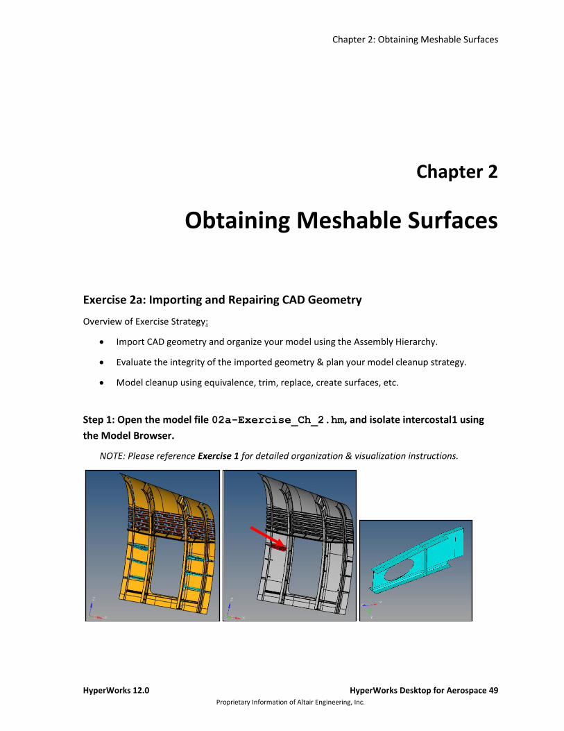
Step 1: Open the model file 02a-Exercise_Ch_2.hm, and isolate intercostal1 using
the Model Browser.
NOTE: Please reference Exercise 1 for detailed organization & visualization instructions.
Chapter 2: Obtaining Meshable Surfaces
50 HyperWorks Desktop for Aerospace HyperWorks 12.0 Proprietary Information of Altair Engineering, Inc
Step 2: Evaluate the integrity of the model & plan your model cleanup strategy
1. Observe where the model has incorrect connectivity and missing or duplicate surfaces.
2. From the menu bar; Geometry > Quick Edit to open the Quick Edit panel.
NOTE: that the surface edges are now colored according to their topology status. This occurs
because Geometry Color is set to Auto ( ).
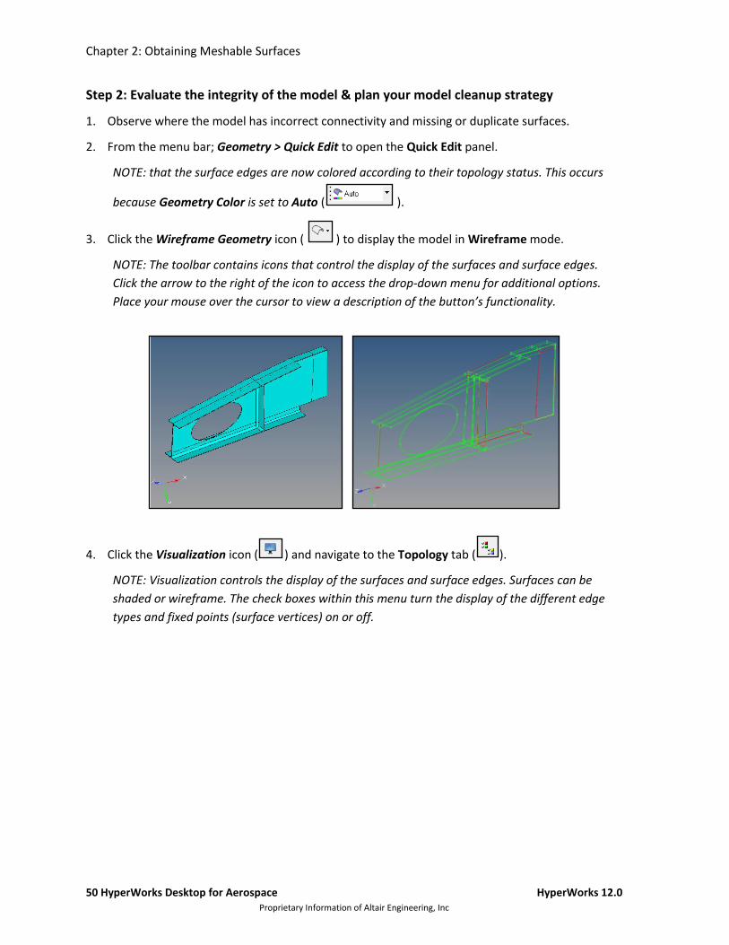
3. Click the Wireframe Geometry icon ( ) to display the model in Wireframe mode.
NOTE: The toolbar contains icons that control the display of the surfaces and surface edges.
Click the arrow to the right of the icon to access the drop-down menu for additional options.
Place your mouse over the cursor to view a description of the button’s functionality.
4. Click the Visualization icon ( ) and navigate to the Topology tab ( ).
NOTE: Visualization controls the display of the surfaces and surface edges. Surfaces can be
shaded or wireframe. The check boxes within this menu turn the display of the different edge
types and fixed points (surface vertices) on or off.
Chapter 2: Obtaining Meshable Surfaces
HyperWorks 12.0 HyperWorks Desktop for Aerospace 51 Proprietary Information of Altair Engineering, Inc.
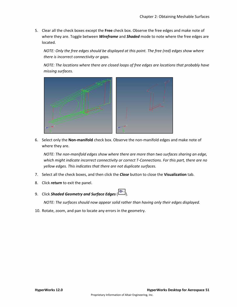
5. Clear all the check boxes except the Free check box. Observe the free edges and make note of
where they are. Toggle between Wireframe and Shaded mode to note where the free edges are
located.
NOTE: Only the free edges should be displayed at this point. The free (red) edges show where
there is incorrect connectivity or gaps.
NOTE: The locations where there are closed loops of free edges are locations that probably have
missing surfaces.
6. Select only the Non-manifold check box. Observe the non-manifold edges and make note of
where they are.
NOTE: The non-manifold edges show where there are more than two surfaces sharing an edge,
which might indicate incorrect connectivity or correct T-Connections. For this part, there are no
yellow edges. This indicates that there are not duplicate surfaces.
7. Select all the check boxes, and then click the Close button to close the Visualization tab.
8. Click return to exit the panel.
9. Click Shaded Geometry and Surface Edges ( ).
NOTE: The surfaces should now appear solid rather than having only their edges displayed.
10. Rotate, zoom, and pan to locate any errors in the geometry.
Chapter 2: Obtaining Meshable Surfaces
52 HyperWorks Desktop for Aerospace HyperWorks 12.0 Proprietary Information of Altair Engineering, Inc
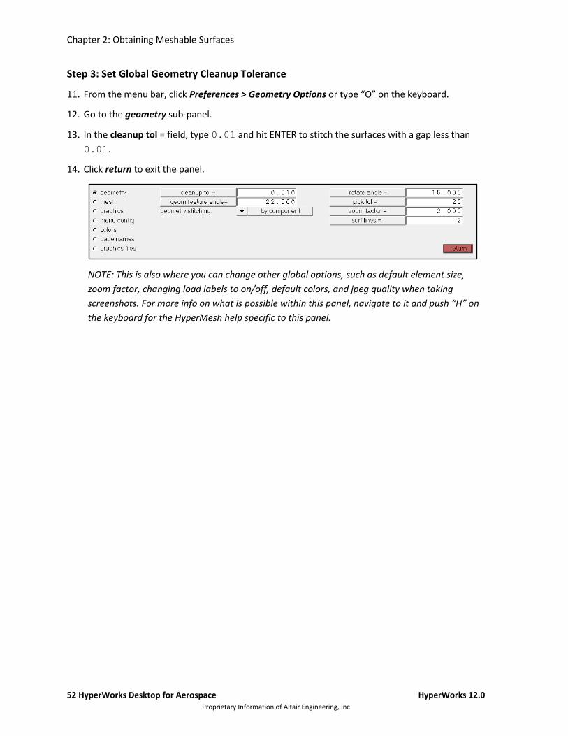
Step 3: Set Global Geometry Cleanup Tolerance
11. From the menu bar, click Preferences > Geometry Options or type “O” on the keyboard.
12. Go to the geometry sub-panel.
13. In the cleanup tol = field, type 0.01 and hit ENTER to stitch the surfaces with a gap less than
0.01.
14. Click return to exit the panel.
NOTE: This is also where you can change other global options, such as default element size,
zoom factor, changing load labels to on/off, default colors, and jpeg quality when taking
screenshots. For more info on what is possible within this panel, navigate to it and push “H” on
the keyboard for the HyperMesh help specific to this panel.
Chapter 2: Obtaining Meshable Surfaces
HyperWorks 12.0 HyperWorks Desktop for Aerospace 53 Proprietary Information of Altair Engineering, Inc.
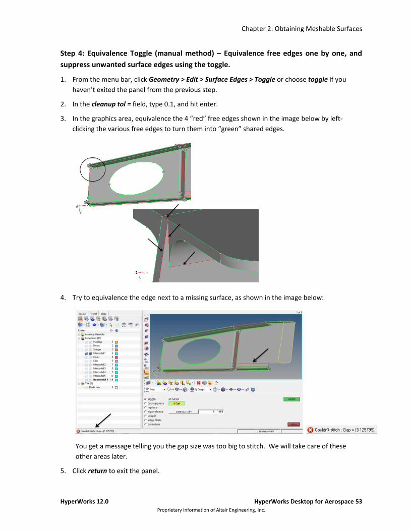
Step 4: Equivalence Toggle (manual method) – Equivalence free edges one by one, and
suppress unwanted surface edges using the toggle.
1. From the menu bar, click Geometry > Edit > Surface Edges > Toggle or choose toggle if you
haven’t exited the panel from the previous step.
2. In the cleanup tol = field, type 0.1, and hit enter.
3. In the graphics area, equivalence the 4 “red” free edges shown in the image below by left-
clicking the various free edges to turn them into “green” shared edges.
4. Try to equivalence the edge next to a missing surface, as shown in the image below:
You get a message telling you the gap size was too big to stitch. We will take care of these
other areas later.
5. Click return to exit the panel.
Chapter 2: Obtaining Meshable Surfaces
54 HyperWorks Desktop for Aerospace HyperWorks 12.0 Proprietary Information of Altair Engineering, Inc
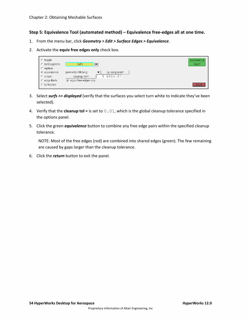
Step 5: Equivalence Tool (automated method) – Equivalence free-edges all at one time.
1. From the menu bar, click Geometry > Edit > Surface Edges > Equivalence.
2. Activate the equiv free edges only check box.
3. Select surfs >> displayed (verify that the surfaces you select turn white to indicate they’ve been
selected).
4. Verify that the cleanup tol = is set to 0.01, which is the global cleanup tolerance specified in
the options panel.
5. Click the green equivalence button to combine any free edge pairs within the specified cleanup
tolerance.
NOTE: Most of the free edges (red) are combined into shared edges (green). The few remaining
are caused by gaps larger than the cleanup tolerance.
6. Click the return button to exit the panel.

Chapter 2: Obtaining Meshable Surfaces
HyperWorks 12.0 HyperWorks Desktop for Aerospace 55 Proprietary Information of Altair Engineering, Inc.
Step 6: Trim & Delete Surfaces
1. For surfaces that extend over an edge, trim the unwanted surface by clicking Geometry > Edit >
Surfaces > Trim with Plane/Surfaces
2. Under the with surfs column, make sure the trim both box is de-selected.
3. Select the first yellow box labeled surfs (the box will have a light blue border when selected),
then choose the surface you want to trim in the graphics area (selected surface will turn white,
see image below).
4. Then select the second yellow surfs box underneath the first one, and choose the surface you
wish to define the trim location with (small surface behind and touching the first selected
surface).
5. Click trim to perform the surface trim operation.
6. Enter the Delete panel by clicking Geometry > Delete > Surfaces or by clicking the delete icon
above the panel region ( ).
7. Make sure surfs is selected in the yellow box, and then select the surface you wish the delete in
the graphics area.
8. Click delete entity.
9. Click return to exit the Delete panel.
NOTE: Trim with surfs/plane is just one option to achieve the desired result. For additional
practice and detailed instructions with trim with nodes, trim with lines, untrim, offset, extend,
and shrink options type “H” while that option is toggled, and the online help will give you
instructions on each specific operation.
10. Click return to exit the Surface Edit panel.
Chapter 2: Obtaining Meshable Surfaces
56 HyperWorks Desktop for Aerospace HyperWorks 12.0 Proprietary Information of Altair Engineering, Inc
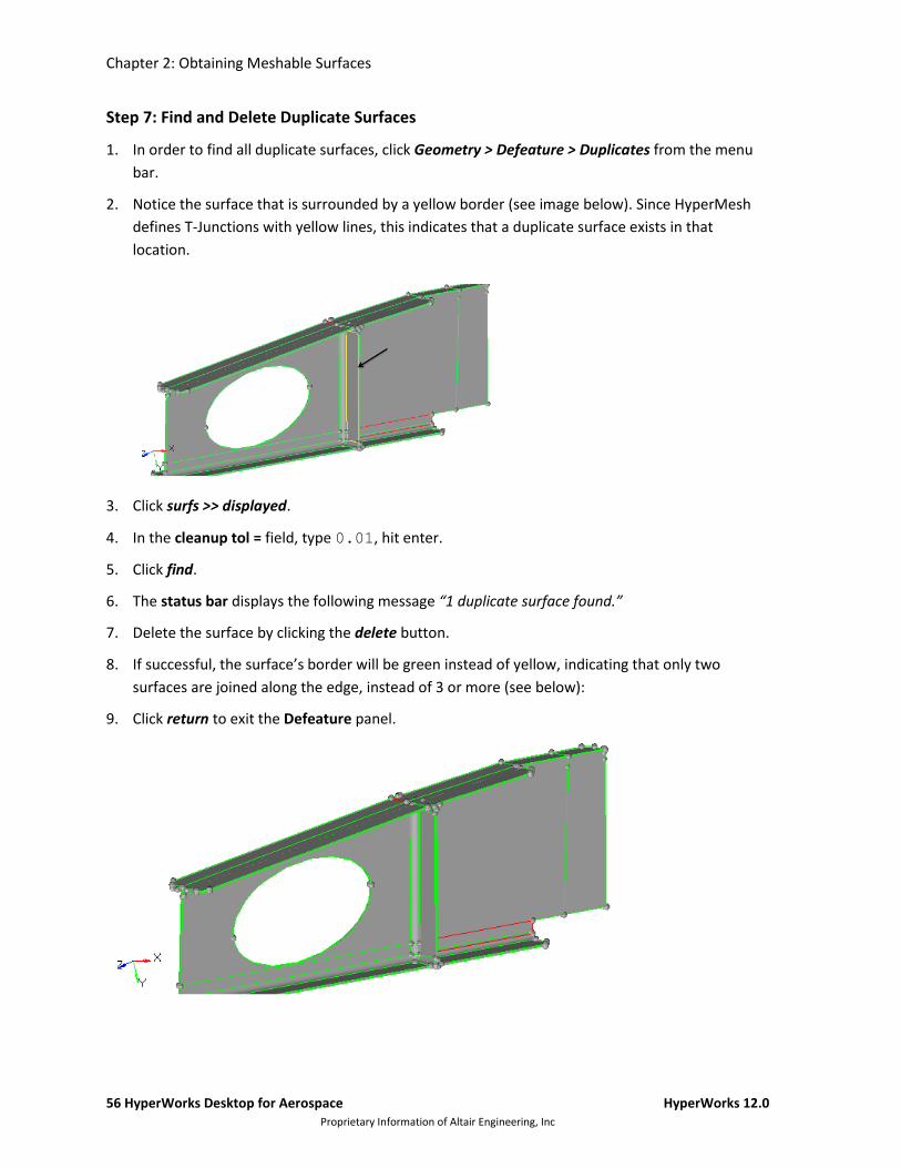
Step 7: Find and Delete Duplicate Surfaces
1. In order to find all duplicate surfaces, click Geometry > Defeature > Duplicates from the menu
bar.
2. Notice the surface that is surrounded by a yellow border (see image below). Since HyperMesh
defines T-Junctions with yellow lines, this indicates that a duplicate surface exists in that
location.
3. Click surfs >> displayed.
4. In the cleanup tol = field, type 0.01, hit enter.
5. Click find.
6. The status bar displays the following message “1 duplicate surface found.”
7. Delete the surface by clicking the delete button.
8. If successful, the surface’s border will be green instead of yellow, indicating that only two
surfaces are joined along the edge, instead of 3 or more (see below):
9. Click return to exit the Defeature panel.
Chapter 2: Obtaining Meshable Surfaces
HyperWorks 12.0 HyperWorks Desktop for Aerospace 57 Proprietary Information of Altair Engineering, Inc.
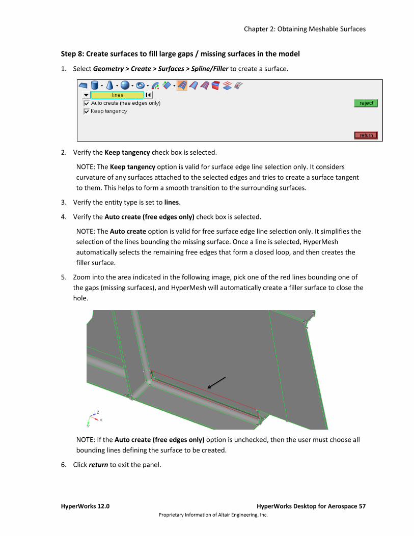
Step 8: Create surfaces to fill large gaps / missing surfaces in the model
1. Select Geometry > Create > Surfaces > Spline/Filler to create a surface.
2. Verify the Keep tangency check box is selected.
NOTE: The Keep tangency option is valid for surface edge line selection only. It considers
curvature of any surfaces attached to the selected edges and tries to create a surface tangent
to them. This helps to form a smooth transition to the surrounding surfaces.
3. Verify the entity type is set to lines.
4. Verify the Auto create (free edges only) check box is selected.
NOTE: The Auto create option is valid for free surface edge line selection only. It simplifies the
selection of the lines bounding the missing surface. Once a line is selected, HyperMesh
automatically selects the remaining free edges that form a closed loop, and then creates the
filler surface.
5. Zoom into the area indicated in the following image, pick one of the red lines bounding one of
the gaps (missing surfaces), and HyperMesh will automatically create a filler surface to close the
hole.
NOTE: If the Auto create (free edges only) option is unchecked, then the user must choose all
bounding lines defining the surface to be created.
6. Click return to exit the panel.

Chapter 2: Obtaining Meshable Surfaces
58 HyperWorks Desktop for Aerospace HyperWorks 12.0 Proprietary Information of Altair Engineering, Inc
Step 9: Combine the remaining free edge pairs using replace.
1. Click Geometry > Edit > Surface Edges > Replace.
2. With the active selector on moved edge: (a light blue border surrounds the yellow box), click the
leftmost free edge in the graphics area (see below):
3. Verify that the selector under retained edge: is now active.
4. Select the rightmost red edge.
5. In the cleanup tol = field, enter 1.0.
6. Click replace.
7. Click return to exit the panel.
8. (Optional): Save your work by clicking File > Save As > Model, with a suggested name 02-
Exercise_Ch_2_CleanGeom.hm or similar, and save in the location of your choice.
Chapter 2: Obtaining Meshable Surfaces
HyperWorks 12.0 HyperWorks Desktop for Aerospace 59 Proprietary Information of Altair Engineering, Inc.
Exercise 2b: Creating and Editing a Midsurface
Overview of Exercise Strategy:
Midsurface using the auto midsurfacing tool.
Evaluate the integrity of the midsurface, and defeature the part
Step 1: Open the model file 02b-Exercise_Ch_2.hm, and isolate intercostal6 using
the Model Browser.
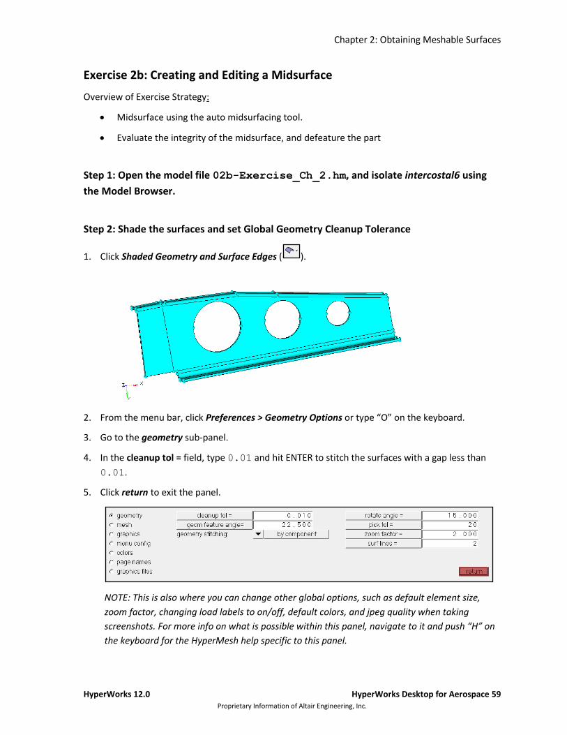
Step 2: Shade the surfaces and set Global Geometry Cleanup Tolerance
1. Click Shaded Geometry and Surface Edges ( ).
2. From the menu bar, click Preferences > Geometry Options or type “O” on the keyboard.
3. Go to the geometry sub-panel.
4. In the cleanup tol = field, type 0.01 and hit ENTER to stitch the surfaces with a gap less than
0.01.
5. Click return to exit the panel.
NOTE: This is also where you can change other global options, such as default element size,
zoom factor, changing load labels to on/off, default colors, and jpeg quality when taking
screenshots. For more info on what is possible within this panel, navigate to it and push “H” on
the keyboard for the HyperMesh help specific to this panel.

Chapter 2: Obtaining Meshable Surfaces
60 HyperWorks Desktop for Aerospace HyperWorks 12.0 Proprietary Information of Altair Engineering, Inc
Step 3: Create the Midsurface
1. From the menu bar, select Geometry > Create > Midsurfaces > Auto. This brings you to the auto
midsurface sub-panel (within the Midsurface panel).
2. Set the switch to surfs.
3. Toggle to closed solid.
4. Click on extraction options and toggle keep sides geometry to insert planes method.
NOTE: The insert planes method on average results in better midsurfaces than keep sides
method on machined parts. For geometry where the inside and outside are mirror-like (as in
stamped parts), the keep sides method is preferred.
5. Toggle to thickness bounds, and change the min thickness to 1.0 and the max thickness to
10.0 and click return.
6. With the surfs button selected, pick one displayed surface. Since the closed solid option is
selected, it will select all surfaces attached (surfaces in the display window will turn white).
7. Click extract.
NOTE: A new component will be created called Middle Surfaces and the new mid plane surfaces
will be placed in it. Additionally the original component will be set to be partially transparent so
the Middle Surfaces can be seen.
8. Turn off the display of the original component using the Model Browser so that only the Middle
Surfaces component is displayed.
Chapter 2: Obtaining Meshable Surfaces
HyperWorks 12.0 HyperWorks Desktop for Aerospace 61 Proprietary Information of Altair Engineering, Inc.
Step 4: Defeature the Midsurface
1. Select Geometry > Defeature > Surface Fillets to enter the Defeature panel.
2. Click on the surfs selector and then click on any surface displayed.
3. Select surfs >> by attached to select all the surfaces in the Intercostal6 middle surface.
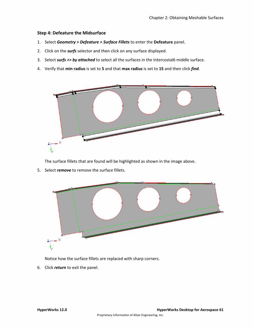
4. Verify that min radius is set to 5 and that max radius is set to 15 and then click find.
The surface fillets that are found will be highlighted as shown in the image above.
5. Select remove to remove the surface fillets.
Notice how the surface fillets are replaced with sharp corners.
6. Click return to exit the panel.