Embed Size (px)
Citation preview
1ROBERT H. PETERSON CO. • 14724 East Proctor Avenue • City of Industry, CA 91746
OWNER’S MANUAL
WARNING: If the information in this manual is not followed exactly, a fi re or explosion may result causing property damage, personal injury or loss of life.
- Do not store or use gasoline or other fl ammable vapors and liquids in the vicinity of this or any other appliance.
- A propane cylinder not connected for use shall not be stored in the vicinity of this or any other appliance.
DANGER
If you smell gas:
1. Shut off gas to the appliance.2. Extinguish any open fl ame.3. If odor continues, keep away from the
appliance and immediately call your gas supplier or fi re department.
Installation and service must be performed by an NFI Certifi ed or other qualifi ed professional installer, service agency, or gas supplier.
09-66
WARNINGImproper installation, adjustment, alteration, service, or maintenance can cause property damage, personal injury, or loss of life. Read the installation, operating and maintenance instructions thoroughly before installing or servicing this equipment.
CODE AND SUPPLY REQUIREMENTS:The installation must conform with local codes and ordinances, or, in the absence of local codes, with the latest National Fuel Gas Code, ANSI Z223.1.
This appliance is designed as an attended appliance. Adults must be present when the unit is operating. DO NOT leave this unit burning when unattended. If this product is left burning unattended, it may cause damage or serious injury.
INSTALLER & CONSUMER: These instructions MUST be retained with this appliance for future reference.
Important: Read these instructions carefully before starting installation of the unit.
IMPORTANTFor safe operation and proper performance of this product and to comply with certification, listings, and building code acceptances, use ONLY Peterson Real-Fyre® controls, parts, and accessories that have been specifi cally listed or certifi ed for use with this burner system. Use of other controls, parts, or accessories is prohibited and will void all warranties, certifi cations, listings, and building code approvals, and may cause property damage, personal injury, and loss of life.
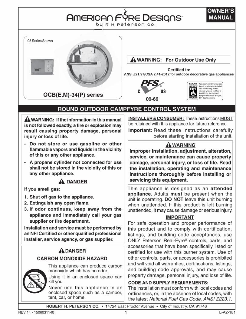
Certifi ed to: ANSI Z21.97/CSA 2.41-2012 for outdoor decorative gas appliances
WARNING: For Outdoor Use Only
DANGER
CARBON MONOXIDE HAZARD
This appliance can produce carbon monoxide which has no odor. Using it in an enclosed space can kill you. Never use this appliance in an enclosed space such as a camper, tent, car, or home.
L-A2-181REV 14 - 1506031140
ROUND OUTDOOR CAMPFYRE CONTROL SYSTEM
05 Series Shown
OCB(E,M)-34(P) series
A
34(P) seri
2
AVERTISSEMENTL'installation, l'ajustement, le changement, le service, ou l'entretien inexact peuvent causer des dégats matériels, le dommage corporel, ou des pertes humaines. Lisez l'installation, l'opération et les instructions d'entretien complètement avant d'installer ou entretenir cet équipement.
CONDITIONS DE CODE ET D'APPROVISIONNEMENT:L'installation doit se conformer aux codes locaux et aux ordonnances, ou, en l'absence des codes locaux, au plus défunt code national de gaz de carburant, la norme ANSI Z223.1.
Cet appareil est conçu comme appareil occupé. Les adultes doivent être présent quand l'unité fonctionne. Ne laissez pas ce burning d'unité si sans surveillance. Si ce produit est laissé sans surveillance brûlant, il peut causer des dommages ou des dommages sérieux.
AVERTISSEMENT: Si l'information en ce manuel n'est pas suivie exactement, une incendie ou une explosion peut résulter entraînant des dégats matériels, le dommage corporel ou des pertes humaines.
- Ne pas entreposer ni utiliser d'essence ou d'autres vapeurs et liquides infl ammables à proximité de cet appareil ou de tout autre.
- Une bouteille de propane non branchée ne doit pas être entreposée à proximité de cet ou tout autre appareil.
DANGER
Si vous sentez une odeur de gaz:
1. Coupez le gaz à l'appareil.2. Éteindre toute fl amme nue.3. Si l'odeur persiste, éloignez-vous de
l'appareil et appelez immédiatement votre fournisseur de gaz ou les pompiers.
L'installation et le service doivent être assurés par un NFI certifi é ou toute autre installateur, agence de service, ou fournisseur professionnelle qualifi ée de gaz.
d'INSTALLATEUR; CONSOMMATEUR: Ces instructions DOIVENT être maintenues avec cet appareil pour la future référence.Important: Lisez ces instructions soigneusement avant
de commencer l'installation de l'unité.
IMPORTANTPour l'exploitation sûre et l'exécution appropriée de ce produit et pour se conformer à la certifi cation, aux listes, et aux acceptations de codes du bâtiment, commandes, pièces, et accessoires de Peterson d'utilisation SEULEMENT Vrais-Fyre® qui ont été spécifi quement énumérés ou certifi és pour l'usage avec ce système de brûleur. L'utilisation d'autres commandes, pièces, ou accessoires est interdite et videra toutes les garanties, certifi cations, listes, et approbations de codes du bâtiment, et peut causer des dégats matériels, le dommage corporel, et des pertes humaines.
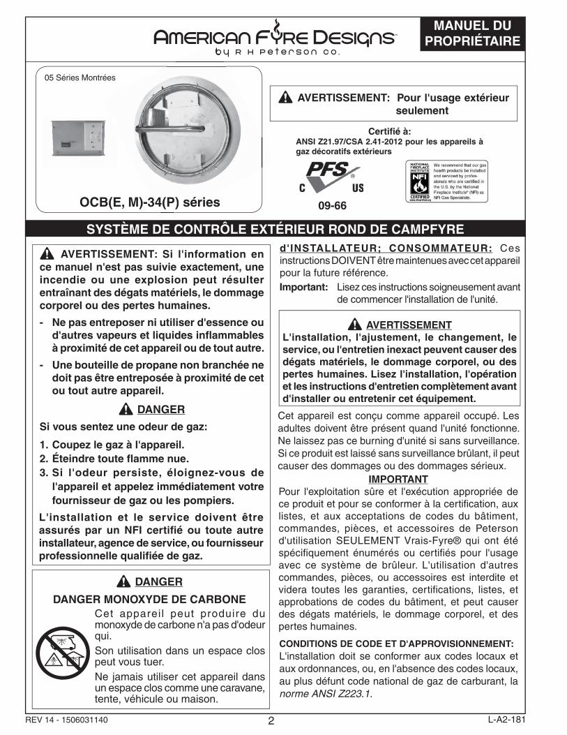
AVERTISSEMENT: Pour l'usage extérieur seulement
09-66
Certifi é à: ANSI Z21.97/CSA 2.41-2012 pour les appareils à gaz décoratifs extérieurs
DANGER
DANGER MONOXYDE DE CARBONECet appareil peut produire du monoxyde de carbone n'a pas d'odeur qui.Son utilisation dans un espace clos peut vous tuer. Ne jamais utiliser cet appareil dans un espace clos comme une caravane, tente, véhicule ou maison.
MANUEL DU PROPRIÉTAIRE
REV 14 - 1506031140 L-A2-181
SYSTÈME DE CONTRÔLE EXTÉRIEUR ROND DE CAMPFYRE
05 Séries Montrées
OCB(E, M)-34(P) séries34(P) séri
3
TABLE OF CONTENTS
L-A2-181REV 14 - 1506031140
4 PARTS LIST
6 PRE-INSTALLATION AND PREPARATION SAFETY GUIDELINES
7 INSTALLATION SAFETY GUIDELINES
7 OPERATING THE UNIT SAFELY AND CORRECTLY
8 IMPORTANT SAFETY INFORMATION
8 MINIMUM CLEARANCE TO COMBUSTIBLES
8 INSTALLATION
9 ENCLOSURE VENTILATION AND DRAINAGE
10 ENCLOSURE REQUIREMENTS
11 COMPONENT SPECIFICATIONS
12 CONTROL PANEL INTERIOR ACCESS (if applicable)
12 CONNECT TO THE GAS SUPPLY
12 LEAK TEST
13 INSTALLING/REPLACING BATTERIES (IF APPLICABLE)
14 CONVERTING TO A DIFFERENT GAS TYPE (PIEZO LIT)
15 CONVERTING TO A DIFFERENT GAS TYPE (MATCH LIT)
16 DECORATIVE MEDIA OPTIONS
16 OPTIONAL CAMPFYRE LOGS
18 OPTIONAL BEACHWOOD LOGS AND/OR VOLCANIC STONE
20 OPTIONAL GLASS/GEMS OR RIVER ROCK ON GLASS/GEMS
21 05 VALVE SERIES LIGHTING INSTRUCTIONS
22 05 INSTRUCTIONS D'ÉCLAIRAGE DE SÉRIE DE VALVE
23 01 VALVE SERIES LIGHTING INSTRUCTIONS
24 01 INSTRUCTIONS D'ÉCLAIRAGE DE SÉRIE DE VALVE
25 MANUAL (PIEZO) LIGHTING INSTRUCTIONS
27 MANUAL (MATCH) LIGHTING INSTRUCTIONS
28 INSTRUCTIONS MANUELLES D'ÉCLAIRAGE
29 OPERATION
29 CLEANING & MAINTENANCE
30 WARRANTY
4
PARTS LIST
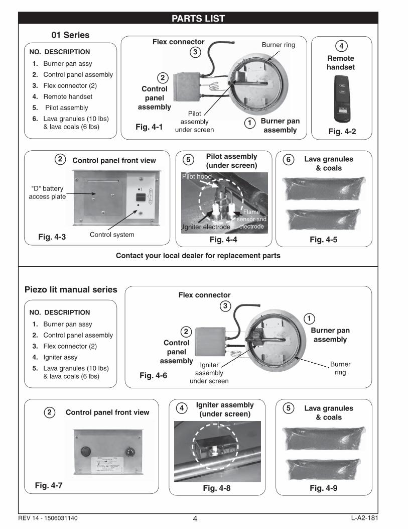
01 Series
Control panel front view2
Control systemFig. 4-3
"D" battery access plate
5 Pilot assembly(under screen)
Fig. 4-4
Pilot hood
Igniter electrode
Flame sensor and electrode
Contact your local dealer for replacement parts
Piezo lit manual series
Control panel front view2
Fig. 4-7
4 Igniter assembly(under screen)
Fig. 4-8
REV 14 - 1506031140 L-A2-181
Remote handset
4
Fig. 4-2
Burner panassembly
Burnerring
Igniter assembly
under screenFig. 4-6
Control panel
assembly
2
Flex connector3
1
Burner panassembly
Burner ring
Pilot assembly
under screenFig. 4-1
Control panel
assembly
2
Flex connector3
1
NO. DESCRIPTION
1. Burner pan assy
2. Control panel assembly
3. Flex connector (2)
4. Remote handset
5. Pilot assembly
6. Lava granules (10 lbs) & lava coals (6 lbs)
NO. DESCRIPTION
1. Burner pan assy
2. Control panel assembly
3. Flex connector (2)
4. Igniter assy
5. Lava granules (10 lbs) & lava coals (6 lbs)
6 Lava granules & coals
Fig. 4-5
5 Lava granules & coals
Fig. 4-9
5
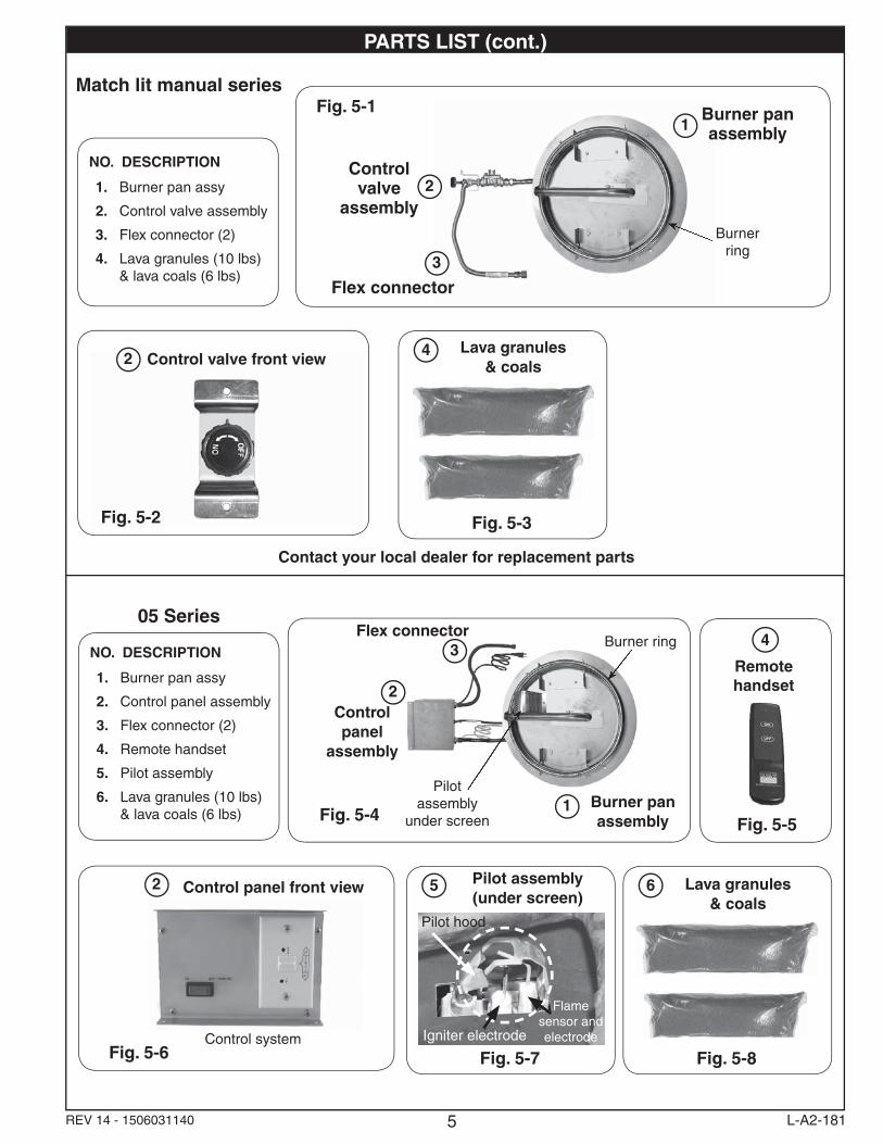
PARTS LIST (cont.)
Contact your local dealer for replacement parts
L-A2-181REV 14 - 1506031140
Remote handset
4
Fig. 5-5Burner panassembly
Burner ring
Pilot assembly
under screenFig. 5-4
Control panel
assembly
2
Flex connector3
1
NO. DESCRIPTION
1. Burner pan assy
2. Control panel assembly
3. Flex connector (2)
4. Remote handset
5. Pilot assembly
6. Lava granules (10 lbs) & lava coals (6 lbs)
6 Lava granules & coals
Fig. 5-8
NO. DESCRIPTION
1. Burner pan assy
2. Control valve assembly
3. Flex connector (2)
4. Lava granules (10 lbs) & lava coals (6 lbs)
Match lit manual series
Control valve front view2
Fig. 5-2
4 Lava granules & coals
Fig. 5-3
Burner panassembly
Burnerring
Fig. 5-1
Control valve
assembly2
Flex connector3
1
05 Series
Control panel front view2
Control systemFig. 5-6
5 Pilot assembly(under screen)
Fig. 5-7
Pilot hood
Igniter electrode
Flame sensor and electrode
6
PRE-INSTALLATION AND PREPARATION SAFETY GUIDELINES
A. A shut-off valve (not included) in the gas line is required. It provides for safety when the unit is not in use and for convenient maintenance and repair. It can be installed remotely (within 6 feet of unit) or at the end of the gas supply stub. Use a pipe joint compound resistant to all gasses on all male fi ttings except fl are fi ttings.
B. Before installing this unit, check the MINIMUM CLEARANCE TO COMBUSTIBLES section to ensure that the surrounding area is properly sized for the installation.
C. The unit is for outdoor use only. DO NOT install or use this appliance inside a building, garage, or any other enclosed area, including recreational vehicles and/or boats. THIS UNIT MUST BE INSTALLED IN SUCH A MANNER THAT ALL VENT OPENINGS ON THE UNIT ENCLOSURE REMAIN CLEAR AND FREE OF ALL OBSTRUCTIONS AT ALL TIMES AND DURING ALL WEATHER CONDITIONS.
D. SOLID FUEL MUST NOT BE BURNED in the unit.
E. CHECK GAS TYPE ( natural gas or propane): The gas supply you intend to use may not be the same as that stated on the unit rating plate as purchased. If the gas supply is different, convert the unit to the gas type you intend to use (IF PERMITTED). See the CONVERTING TO A DIFFERENT GAS TYPE SECTION. If you are unsure, contact the dealer for assistance. ONLY MANUAL UNITS ARE CONVERTIBLE.
F. FOR NATURAL GAS: The minimum inlet gas-supply pressure for purposes of input adjustment is 5" water column (w.c.), and the maximum inlet gas-supply pressure is 10.5 " w.c.
FOR PROPANE GAS: The minimum inlet gas-supply pressure for purposes of input adjustment is 11" w.c., and the maximum inlet gas-supply pressure is 13" w.c. DO NOT INSTALL THIS UNIT IF MINIMUM PRESSURE IS NOT AVAILABLE OR IF MAXIMUM PRESSURE IS EXCEEDED.
G. The gas piping system must be sized to provide minimum inlet pressure at the maximum fl ow rate (BTU/hr). Undue pressure loss will occur if the pipe is too small, or the run is too long. Gas supply pipe must be 1/2" minimum interior diameter. If the gas line is longer than 20', a larger diameter line may be necessary. Refer to the NFPA 54 guidelines for further details.
H. For installations at elevations above 2,000 ft., contact your local dealer or gas supplier before installing. Input ratings should be reduced approximately 4% for each 1,000 ft. above sea level. Refer to the National Fuel Gas Code.
I. The unit and its individual shut-off valve must be disconnected from the gas-supply piping system during any pressure testing of that system at test pressures in excess of 1/2 psi (3.5 kPa). This is accomplished by closing the gas-supply line valve. The unit must be isolated from the gas-supply piping system by closing its individual manual shut-off valve during any pressure testing of the gas-supply piping system at test pressures equal to or less than 1/2 psi (3.5 kPa).
J. DO NOT CONNECT THIS UNIT TO A PORTABLE L.P. CYLINDER. IT MUST BE CONNECTED TO A FIXED PIPING SYSTEM. The installation must conform with local codes, or in the absence of local codes with the National Fuel Gas Code, ANSI Z223.1/NFPA 54; International Fuel Gas Code, Natural Gas and Propane Installation Code, CSA B149.1; or Propane Storage and Handling Code, B149.2, as applicable. The appliance, when installed, must be electrically grounded in accordance with local codes, or in the absence of local codes with the National Electrical Code, ANSI/NFPA 70; or the Canadian Electrical Code, CSA C22.1, if applicable.
Electrical Grounding Instructions - This appliance is equipped with a three-prong (grounding) plug for your protection against shock hazard and should be plugged directly into a properly grounded three-prong receptacle. Do not cut or remove the grounding prong from this plug.
K. INSTALLER NOTE: This unit should be installed so that it can be removed if service is required.
L. GAS-SUPPLY PLUMBING REQUIREMENTS
Apply only joint compounds that are resistant to all gasses on all male pipe fi ttings. Make sure to tighten every joint securely. Do not use pipe joint compound to connect fl are fi ttings. Bring the gas-supply pipe up from beneath the enclosure near its center.
CAUTION: Installation and maintenance must be done by an NFI Certifi ed or other qualifi ed professional service technician. Installer, read these instructions before installing this product. Be sure you understand all safety precautions and warnings contained in this manual.
7
OPERATING THE UNIT SAFELY AND CORRECTLY
INSTALLATION SAFETY GUIDELINESA. Carefully inspect for shipping damage. If any parts are damaged, call the dealer.
B. Installation and repair should be done by a qualifi ed professional service technician. The appliance should be inspected before use and at least annually by a qualifi ed service person. More frequent cleaning may be required as necessary. It is imperative that control compartment, burners and circulating air passageways of the appliance are kept clean.
C. WEAR GLOVES AND USE EXTREME CAUTION WHENEVER INSTALLING AND HANDLING THIS PRODUCT AND ITS ACCESSORIES AS CERTAIN COMPONENTS HAVE SHARP EDGES THAT CAN CAUSE PERSONAL INJURY.
D. Correct installation and proper placement of the unit and decorative media is crucial to the safe performance of the unit. See installation instructions for further information.
E. DO NOT install the unit under any overhead combustible materials.
F. Ensure that the unit enclosure is installed on a hard, level, non-combustible surface.
G. Ensure that the unit enclosure is installed in such a manner that all vent openings on the enclosure remain clear and free of all obstructions at all times and during all weather conditions.
H. Due to high temperatures, the unit enclosure must be located out of traffi c areas and away from combustibles.
I. Ensure all enclosure construction, ventilation, and water drainage requirements are met. See INSTALLATION section for details.
J. NEVER COVER THE BURNER SCREEN WITH DECORATIVE MEDIA OR ANY OTHER ITEMS. THIS WILL IMPAIR ITS EFFICIENCY AND CAUSE THE UNIT TO MALFUNCTION.
A. This product is a decorative gas appliance. It is not a cooking appliance.
B. SOLID FUEL MUST NOT BE BURNED in the unit.
C. When shutting the unit down—be sure to TURN THE CONTROL VALVE FULLY OFF.
D. Children MUST be supervised when they are in the area of this appliance.
E. DO NOT sit or place any part of the body, clothing, or other fl ammable materials on or near the unit surround. Children and adults should be alerted to the hazard of high surface temperatures and should stay away to avoid burns or clothing ignition. DO NOT lean over the unit when lighting or when in use.
F. Every time you use the unit, make sure that:
1. The area around the unit enclosure is clear and free from combustible materials, gasoline and other fl ammable vapors and liquids.
2. There is no blockage of the airfl ow through the vent openings located on the unit enclosure.
3. THE SCREEN IS NOT COVERED OR BLOCKED WITH DECORATIVE MEDIA OR ANY OTHER ITEMS.
G. WARNING: HOT WHILE IN OPERATION AND FOLLOWING OPERATION. Serious injury can occur! DO NOT throw trash, paper, or other fl ammable materials onto the unit. DO NOT leave in operation when unattended.
WARNING: DO NOT operate this unit in the rain.
WARNING: DO NOT operate this unit in high-wind conditions. Operating in high-wind conditions may expose your unit to direct fl ame, which will result in damage to the fi nish.
H. DO NOT continue using if you smell unusual odors, or have headaches, nausea, or dizziness.
I. DO NOT store any combustible materials, gasoline, and any other fl ammable vapors/liquids in the vicinity of the unit. Provide adequate clearance for servicing and operation.
J. Matches, paper, garbage, or any other material must not be thrown onto the unit or into the fl ame.
K. DO NOT use the unit if any part of it has been underwater. Immediately call a qualifi ed professional service technician to inspect the unit and to replace any part of the control system and any gas control that has been underwater.
8
BE CAREFULIf not installed and used correctly per these instructions,
this product can cause serious injury.
CAUTION: Installation and maintenance must be done by an NFI Certifi ed or other qualifi ed professional installer. Read these instructions before installing this unit. Be sure you understand all safety precautions and warnings contained in this manual.
A. FOR OUTDOOR USE ONLY.
B. When shutting the unit down—be sure to TURN THE CONTROL VALVE FULLY OFF.
C. WARNING: CARBON MONOXIDE POISONING MAY LEAD TO DEATH. DO NOT MODIFY THIS UNIT OR ITS CONTROLS, EXCEPT AS PROVIDED FOR IN THIS MANUAL. Any other change may be dangerous. Improper installation or use of the unit can cause serious injury or death from fi re, burns, explosions, or carbon monoxide poisoning.
D. Check state and local codes to determine if the unit is permitted in your locality before installation.
E. The manual valve allows adjustable fl ame height and heat output. THESE SETTINGS MUST ALWAYS BE HIGH ENOUGH FOR THE FLAME TO BE CLEARLY VISIBLE.
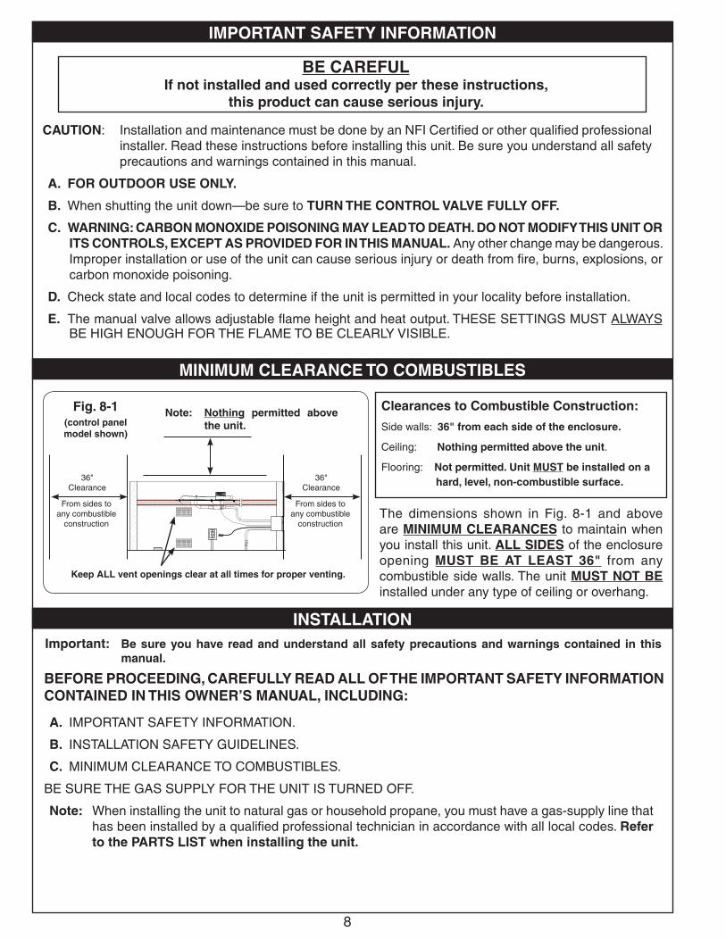
The dimensions shown in Fig. 8-1 and above are MINIMUM CLEARANCES to maintain when you install this unit. ALL SIDES of the enclosure opening MUST BE AT LEAST 36" from any combustible side walls. The unit MUST NOT BE installed under any type of ceiling or overhang.
Clearances to Combustible Construction:
Side walls: 36" from each side of the enclosure.
Ceiling: Nothing permitted above the unit.
Flooring: Not permitted. Unit MUST be installed on a hard, level, non-combustible surface.
BEFORE PROCEEDING, CAREFULLY READ ALL OF THE IMPORTANT SAFETY INFORMATION CONTAINED IN THIS OWNER’S MANUAL, INCLUDING:
A. IMPORTANT SAFETY INFORMATION.
B. INSTALLATION SAFETY GUIDELINES.
C. MINIMUM CLEARANCE TO COMBUSTIBLES.
BE SURE THE GAS SUPPLY FOR THE UNIT IS TURNED OFF.
Note: When installing the unit to natural gas or household propane, you must have a gas-supply line that has been installed by a qualifi ed professional technician in accordance with all local codes. Refer to the PARTS LIST when installing the unit.
Fig. 8-1(control panelmodel shown)
Note: Nothing permitted above the unit.
36"Clearance
From sides to any combustible
construction
Important: Be sure you have read and understand all safety precautions and warnings contained in this manual.
36"Clearance
From sides to any combustible
construction
IMPORTANT SAFETY INFORMATION
MINIMUM CLEARANCE TO COMBUSTIBLES
INSTALLATION
Keep ALL vent openings clear at all times for proper venting.
9
INSTALLATION (Cont.)
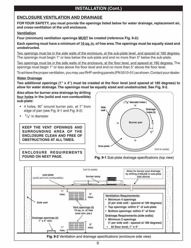
ENCLOSURE VENTILATION AND DRAINAGEFOR YOUR SAFETY, you must provide the openings listed below for water drainage, replacement air, and cross-ventilation of the unit enclosure.
VentilationFour (minimum) ventilation openings MUST be created (reference Fig. 9-2):
Each opening must have a minimum of 10 sq. in. of free area. The openings must be equally sized and unobstructed.
Two openings must be in the side walls of the enclosure, at the sub-plate level, and spaced at 180 degrees. The openings must begin 1" or less below the sub-plate and end no more than 5" below the sub-plate.
Two openings must be in the side walls of the enclosure, at the fl oor level, and spaced at 180 degrees. The openings must begin 1" or less above the fl oor level and end no more than 5" above the fl oor level.
To achieve the proper ventilation, you may use RHP venting panels (PN 5510-01) as shown. Contact your dealer.
Water DrainageTwo additional openings (1" x 4") must be created at the fl oor level (and spaced at 180 degrees) to allow for water drainage. The openings must be equally sized and unobstructed. See Fig. 9-2.
Also allow for burner area drainage by drilling four holes in the (solid and non-combustible) sub-plate:
• 4 holes, 90˚ around burner pan, at 1" from edge of pan (see Fig. 9-1 and Fig. 9-2)
• 1/4" in diameter
Fig. 9-2 Ventilation and drainage specifi cations (enclosure side view)
Allow for burner area drainageby drilling 4 HOLES in sub-plate
(see above)
KEEP THE VENT OPENINGS AND SURROUNDING AREA OF THE ENCLOSURE CLEAN AND FREE OF OBSTRUCTIONS AT ALL TIMES.
Vent openings (4)10 sq. in. of free area min. (ea.)
1"max. 5"
max.
1"max.
5"max.
Drainage openings (2)1" x 4" min.
Ventilation Requirements:• Minimum 4 openings
(2 per side wall - spaced at 180 degrees) • Top openings: within 5" of sub-plate• Bottom openings: within 5" of fl oor
Drainage Requirements (side walls):• Minimum 2 openings
(1 per side wall - spaced at 180 degrees) • At fl oor level, 1" x 4"
sub-plate(solid and non-combustible)
(not to scale)
burner assy.
Side wall
ENCLOSURE REQUIREMENTS FOUND ON NEXT PAGE. Fig. 9-1 Sub-plate drainage specifi cations (top view)
1"
(not to scale)
Burner pan
Sub-plate
Drainage holes (4)
Side wall
( 1/4" diameter holes )
10
INSTALLATION (Cont.)
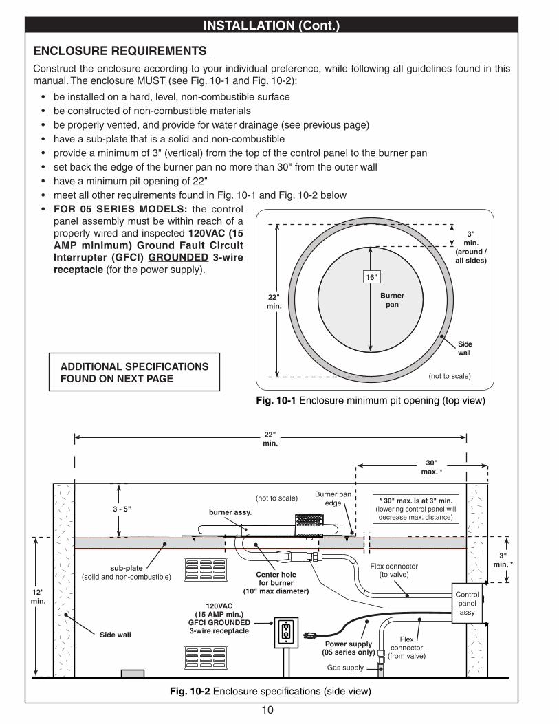
Fig. 10-2 Enclosure specifi cations (side view)
3" min. *
30" max. *
3 - 5"
Center holefor burner
(10" max diameter) Control panel assy
Flex connector (to valve)
Flex connector
(from valve)
Power supply(05 series only)
Gas supply
120VAC(15 AMP min.)
GFCI GROUNDED 3-wire receptacle
ENCLOSURE REQUIREMENTS Construct the enclosure according to your individual preference, while following all guidelines found in this manual. The enclosure MUST (see Fig. 10-1 and Fig. 10-2):
• be installed on a hard, level, non-combustible surface• be constructed of non-combustible materials• be properly vented, and provide for water drainage (see previous page)• have a sub-plate that is a solid and non-combustible• provide a minimum of 3" (vertical) from the top of the control panel to the burner pan• set back the edge of the burner pan no more than 30" from the outer wall• have a minimum pit opening of 22"• meet all other requirements found in Fig. 10-1 and Fig. 10-2 below• FOR 05 SERIES MODELS: the control
panel assembly must be within reach of a properly wired and inspected 120VAC (15 AMP minimum) Ground Fault Circuit Interrupter (GFCI) GROUNDED 3-wire receptacle (for the power supply).
ADDITIONAL SPECIFICATIONS FOUND ON NEXT PAGE
(not to scale)
sub-plate(solid and non-combustible)
Side wall
22" min.
Fig. 10-1 Enclosure minimum pit opening (top view)
(not to scale)
22" min.
16"
3"min.
(around / all sides)
Burner pan
Side wall
* 30" max. is at 3" min.(lowering control panel will decrease max. distance)
Burner pan edge
burner assy.
12" min.
11
INSTALLATION (Cont.)
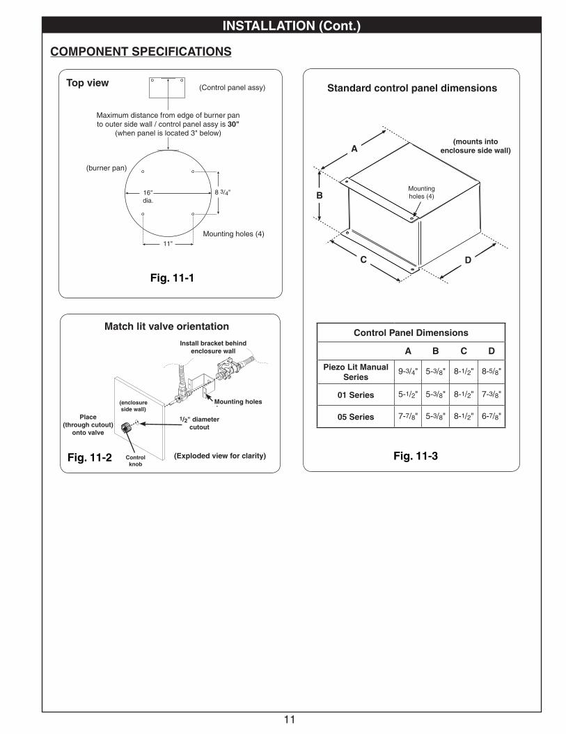
Fig. 11-1
Top view
Maximum distance from edge of burner pan to outer side wall / control panel assy is 30"
(when panel is located 3" below)
8 3/4"
11"
Mounting holes (4)
16"dia.
Fig. 11-2
Match lit valve orientation
1/2" diameter cutout
Install bracket behind enclosure wall
Place(through cutout)
onto valve
(enclosureside wall)
Control knob
(Exploded view for clarity)
Mounting holes
COMPONENT SPECIFICATIONS
Standard control panel dimensions
Mounting holes (4)
Control Panel Dimensions
A B C D
Piezo Lit Manual Series
9-3/4" 5-3/8" 8-1/2" 8-5/8"
01 Series 5-1/2" 5-3/8" 8-1/2" 7-3/8"
05 Series 7-7/8" 5-3/8" 8-1/2" 6-7/8"
Fig. 11-3
DC
B
A(mounts into
enclosure side wall)
(Control panel assy)
(burner pan)
12
INSTALLATION (Cont.)
CONNECT TO THE GAS SUPPLYCAUTION: DO NOT connect this unit to a portable L.P.
Cylinder. It must be connected to a fi xed piping system.
Important: Before installation, be sure the gas supply (household propane or natural gas) is turned off at its source.
Important: Locate the gas supply line out of pathways where people may trip over it or in areas where the line may be subject to accidental damage (if applicable).
Your unit is equipped with a fl ex connector that is to be routed to a gas supply appropriate for your setup. Additional gas components may be required. Consult a qualifi ed professional service technician, and your local dealer. Follow the guidelines below.
1. Bring the gas supply pipe up from beneath the unit, or through the side of the unit. Observe all local codes.Note: A shut-off valve (not included) in the gas line is required. It can be installed remotely (within 6 feet
of unit) or at the end of the gas supply stub. Use a pipe joint compound resistant to all gasses on all male fi ttings except fl are fi ttings. See Fig. 12-1 for an example.
2. If shut-off valve is connected to end of gas supply stub:• Connect the fl ex connector (on rear of valve assembly) to the shut-off valve (see Fig. 12-1). Tighten
securely.
If shut-off valve is installed remotely:• Install the supplied fl are adapter to the gas supply using a pipe joint compound resistant to all gasses
(see Fig. 12-1). Tighten securely.
• Connect the fl ex connector (on rear of valve assembly) to the fl are adapter (see Fig. 12-1). Tighten securely.
CONNECT TO A POWER SUPPLY (05 Series Only)Connect the power supply coming from the control panel to a properly wired and inspected 120VAC (15 AMP minimum) GFCI GROUNDED 3-wire receptacle (not included). Reference the ENCLOSURE REQUIREMENTS section for details.
LEAK TESTTurn on the gas supply, ignite the burner, and test at all connections for leaks using a soapy water solution. If bubbles appear, a leak is present. Turn off the gas and tighten at all connections. Repeat until no leaks are present. If a leak persists, turn off the gas supply and contact the local gas company or dealer. NEVER USE A FLAME TO CHECK FOR LEAKS.
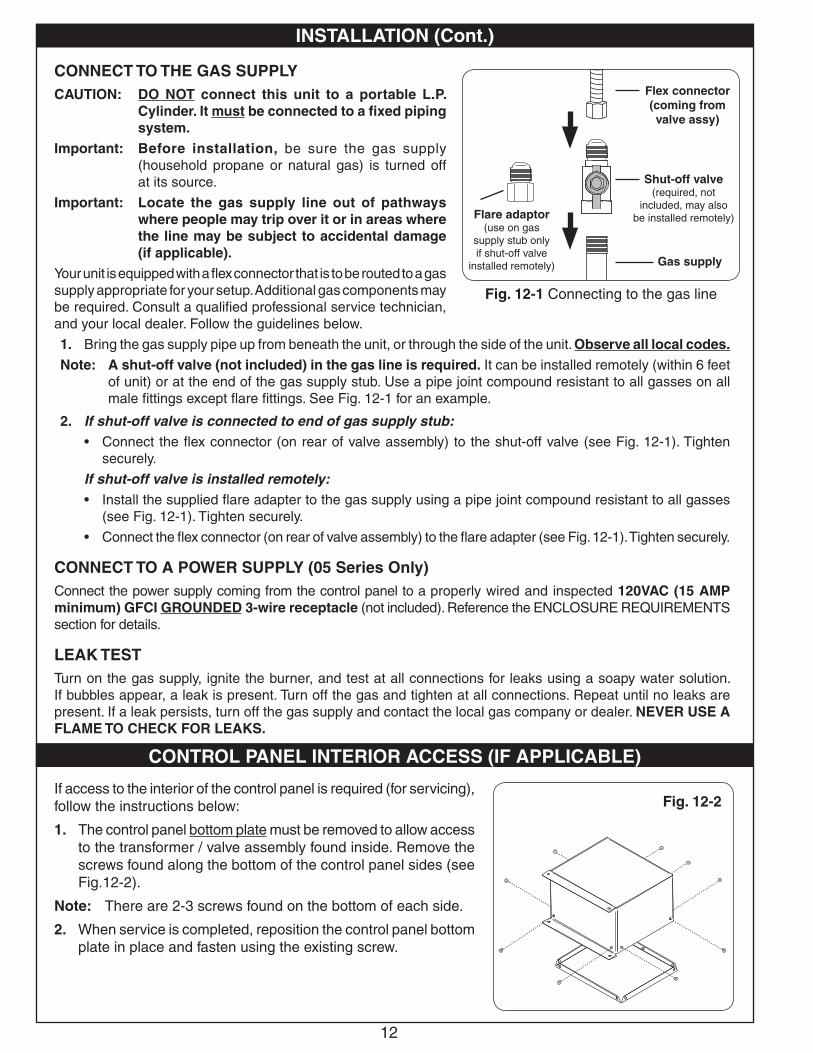
CONTROL PANEL INTERIOR ACCESS (IF APPLICABLE)
If access to the interior of the control panel is required (for servicing), follow the instructions below:
1. The control panel bottom plate must be removed to allow access to the transformer / valve assembly found inside. Remove the screws found along the bottom of the control panel sides (see Fig.12-2).
Note: There are 2-3 screws found on the bottom of each side.
2. When service is completed, reposition the control panel bottom plate in place and fasten using the existing screw.
Fig. 12-2
Fig. 12-1 Connecting to the gas line
Gas supply
Flare adaptor(use on gas
supply stub only if shut-off valve
installed remotely)
Flex connector(coming from valve assy)
Shut-off valve(required, not
included, may also be installed remotely)
13
INSTALLING/REPLACING THE BATTERIES FOR 01 SERIES
To access the "D" battery pack, unscrew the access plate on the left side of the control panel. Only unscrew the large retaining screw. Grip the top half of the access plate and pull it out to expose the "D" battery pack (Fig. 13-4). Replace the old batteries with two (2) new "D" batteries. Return the access plate into the control panel. Screw in the large retaining screw.
To access the "AA" battery pack, unscrew and remove the two (2) retaining screws on the control system. Pull out the control system and then slide open the battery pack lid as shown in Fig. 13-5. Replace the old batteries with four (4) new "AA" batteries. Resecure the battery pack lid and return the control system into the control panel. Screw in the two (2) retaining screws.
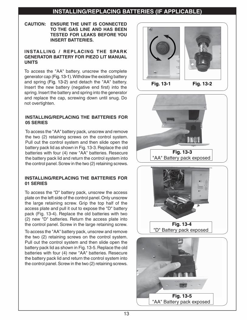
CAUTION: ENSURE THE UNIT IS CONNECTED TO THE GAS LINE AND HAS BEEN TESTED FOR LEAKS BEFORE YOU INSERT BATTERIES.
Fig. 13-4"D" Battery pack exposed
Fig. 13-5"AA" Battery pack exposed
Fig. 13-1 Fig. 13-2
INSTALLING/REPLACING BATTERIES (IF APPLICABLE)
INSTALLING / REPLACING THE SPARK GENERATOR BATTERY FOR PIEZO LIT MANUAL UNITS
To access the "AA" battery, unscrew the complete generator cap (Fig. 13-1). Withdraw the existing battery and spring (Fig. 13-2) and detach the "AA" battery. Insert the new battery (negative end fi rst) into the spring. Insert the battery and spring into the generator and replace the cap, screwing down until snug. Do not overtighten.
INSTALLING/REPLACING THE BATTERIES FOR 05 SERIES
To access the "AA" battery pack, unscrew and remove the two (2) retaining screws on the control system. Pull out the control system and then slide open the battery pack lid as shown in Fig. 13-3. Replace the old batteries with four (4) new "AA" batteries. Resecure the battery pack lid and return the control system into the control panel. Screw in the two (2) retaining screws.
Fig. 13-3"AA" Battery pack exposed
14
To convert PIEZO LIT MANUAL UNITS (only) from propane to natural gas or from natural to propane gas, carefully follow the steps below:
1. SHUT OFF THE GAS SUPPLY TO THE UNIT AND ANY NEARBY ELECTRICAL SOURCES OR APPLIANCES.
2. If present, remove all decorative media from the unit.
3. If installed, remove the screws attaching the burner pan to your enclosure.
4. The control panel bottom plate must be removed to allow access to the valve assembly found inside. Remove the screws found along the bottom of the control panel sides. (There are 2-3 screws found on the bottom of each side.)
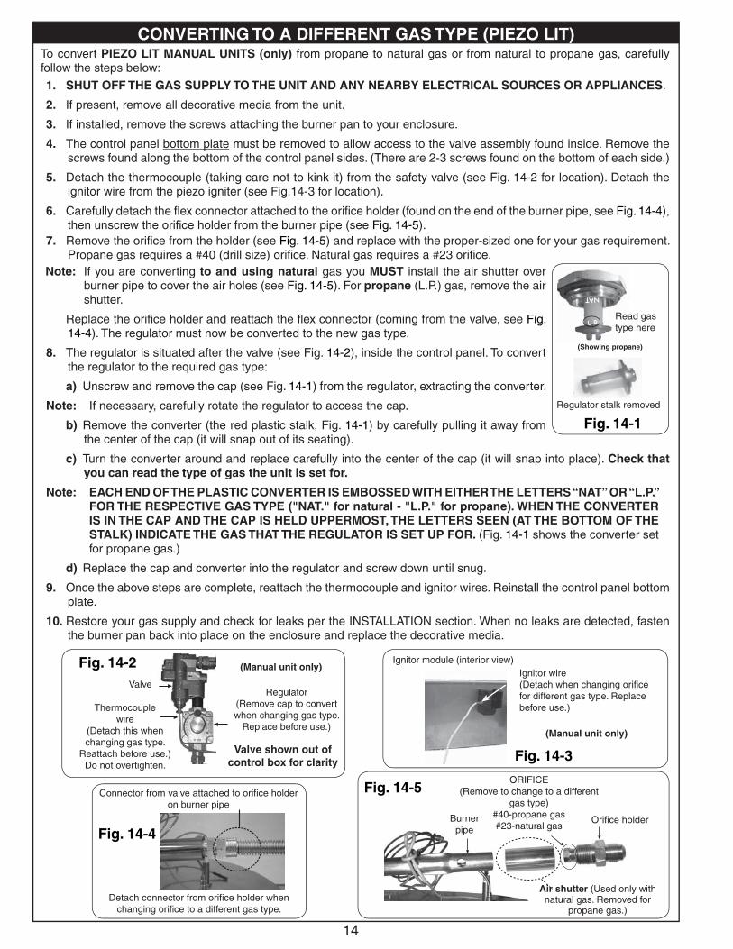
5. Detach the thermocouple (taking care not to kink it) from the safety valve (see Fig. 14-2 for location). Detach the ignitor wire from the piezo igniter (see Fig.14-3 for location).
6. Carefully detach the fl ex connector attached to the orifi ce holder (found on the end of the burner pipe, see Fig. 14-4), then unscrew the orifi ce holder from the burner pipe (see Fig. 14-5).
Note: If you are converting to and using natural gas you MUST install the air shutter over burner pipe to cover the air holes (see Fig. 14-5). For propane (L.P.) gas, remove the air shutter.
Replace the orifi ce holder and reattach the fl ex connector (coming from the valve, see Fig. 14-4). The regulator must now be converted to the new gas type.
8. The regulator is situated after the valve (see Fig. 14-2), inside the control panel. To convert the regulator to the required gas type:
a) Unscrew and remove the cap (see Fig. 14-1) from the regulator, extracting the converter.
Note: If necessary, carefully rotate the regulator to access the cap.
b) Remove the converter (the red plastic stalk, Fig. 14-1) by carefully pulling it away from the center of the cap (it will snap out of its seating).
c) Turn the converter around and replace carefully into the center of the cap (it will snap into place). Check that you can read the type of gas the unit is set for.
Note: EACH END OF THE PLASTIC CONVERTER IS EMBOSSED WITH EITHER THE LETTERS “NAT” OR “L.P.” FOR THE RESPECTIVE GAS TYPE ("NAT." for natural - "L.P." for propane). WHEN THE CONVERTER IS IN THE CAP AND THE CAP IS HELD UPPERMOST, THE LETTERS SEEN (AT THE BOTTOM OF THE STALK) INDICATE THE GAS THAT THE REGULATOR IS SET UP FOR. (Fig. 14-1 shows the converter set for propane gas.)
d) Replace the cap and converter into the regulator and screw down until snug.
9. Once the above steps are complete, reattach the thermocouple and ignitor wires. Reinstall the control panel bottom plate.
10. Restore your gas supply and check for leaks per the INSTALLATION section. When no leaks are detected, fasten the burner pan back into place on the enclosure and replace the decorative media.
Connector from valve attached to orifi ce holder on burner pipe
Detach connector from orifi ce holder when changing orifi ce to a different gas type.
Fig. 14-4
Fig. 14-2Valve
Thermocouplewire
(Detach this when changing gas type.
Reattach before use.)Do not overtighten.
Regulator(Remove cap to convert when changing gas type.
Replace before use.)
Fig. 14-3
Ignitor module (interior view)Ignitor wire (Detach when changing orifi ce for different gas type. Replace before use.)
Fig. 14-5
Burner pipe
Air shutter (Used only with natural gas. Removed for
propane gas.)
Orifi ce holder
Fig. 14-1
(Showing propane)
Read gas type here
Regulator stalk removed
(Manual unit only)
(Manual unit only)
CONVERTING TO A DIFFERENT GAS TYPE (PIEZO LIT)
Valve shown out of control box for clarity
ORIFICE(Remove to change to a different
gas type)#40-propane gas#23-natural gas
7. Remove the orifi ce from the holder (see Fig. 14-5) and replace with the proper-sized one for your gas requirement. Propane gas requires a #40 (drill size) orifi ce. Natural gas requires a #23 orifi ce.
15
To convert MATCH LIT MANUAL UNITS (only) from propane to natural gas or from natural to propane gas, carefully follow the steps below:1. SHUT OFF THE GAS SUPPLY TO THE UNIT AND ANY NEARBY ELECTRICAL SOURCES OR
APPLIANCES.
2. If present, remove all decorative media from the unit.
3. Remove the screws attaching the burner pan to your enclosure.
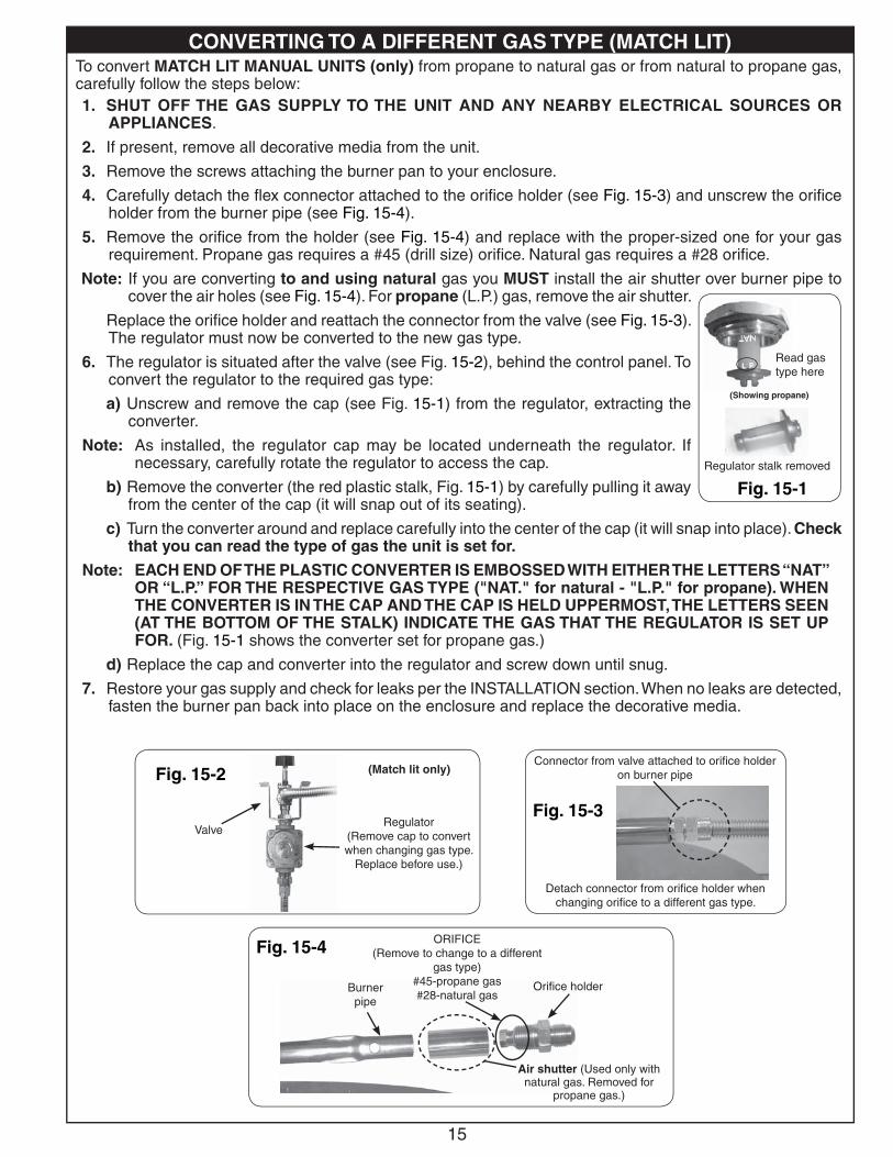
4. Carefully detach the fl ex connector attached to the orifi ce holder (see Fig. 15-3) and unscrew the orifi ce holder from the burner pipe (see Fig. 15-4).
5. Remove the orifi ce from the holder (see Fig. 15-4) and replace with the proper-sized one for your gas requirement. Propane gas requires a #45 (drill size) orifi ce. Natural gas requires a #28 orifi ce.
Note: If you are converting to and using natural gas you MUST install the air shutter over burner pipe to cover the air holes (see Fig. 15-4). For propane (L.P.) gas, remove the air shutter.
Replace the orifi ce holder and reattach the connector from the valve (see Fig. 15-3). The regulator must now be converted to the new gas type.
6. The regulator is situated after the valve (see Fig. 15-2), behind the control panel. To convert the regulator to the required gas type:
a) Unscrew and remove the cap (see Fig. 15-1) from the regulator, extracting the converter.
Note: As installed, the regulator cap may be located underneath the regulator. If necessary, carefully rotate the regulator to access the cap.
b) Remove the converter (the red plastic stalk, Fig. 15-1) by carefully pulling it away from the center of the cap (it will snap out of its seating).
c) Turn the converter around and replace carefully into the center of the cap (it will snap into place). Check that you can read the type of gas the unit is set for.
Note: EACH END OF THE PLASTIC CONVERTER IS EMBOSSED WITH EITHER THE LETTERS “NAT” OR “L.P.” FOR THE RESPECTIVE GAS TYPE ("NAT." for natural - "L.P." for propane). WHEN THE CONVERTER IS IN THE CAP AND THE CAP IS HELD UPPERMOST, THE LETTERS SEEN (AT THE BOTTOM OF THE STALK) INDICATE THE GAS THAT THE REGULATOR IS SET UP FOR. (Fig. 15-1 shows the converter set for propane gas.)
d) Replace the cap and converter into the regulator and screw down until snug.
7. Restore your gas supply and check for leaks per the INSTALLATION section. When no leaks are detected, fasten the burner pan back into place on the enclosure and replace the decorative media.
Connector from valve attached to orifi ce holder on burner pipe
Detach connector from orifi ce holder when changing orifi ce to a different gas type.
Fig. 15-3
Fig. 15-2
ValveRegulator
(Remove cap to convert when changing gas type.
Replace before use.)
Fig. 15-4
Burner pipe
Air shutter (Used only with natural gas. Removed for
propane gas.)
Orifi ce holder
Fig. 15-1
(Showing propane)
Read gas type here
Regulator stalk removed
(Match lit only)
CONVERTING TO A DIFFERENT GAS TYPE (MATCH LIT)
ORIFICE(Remove to change to a different
gas type)#45-propane gas#28-natural gas
16
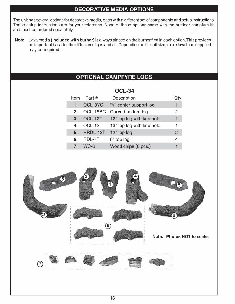
Note: Photos NOT to scale.
1
43
2 2
7
6
55
Item Part # Description Qty
1. OCL-8YC “Y” center support log 1
2. OCL-15BC Curved bottom log 2
3. OCL-12T 12" top log with knothole 1
4. OCL-13T 13" top log with knothole 1
5. HRDL-12T 12" top log 2
6. RDL-7T 8" top log 4
7. WC-6 Wood chips (6 pcs.) 1
The unit has several options for decorative media, each with a different set of components and setup instructions. These setup instructions are for your reference. None of these options come with the outdoor campfyre kit and must be ordered separately.
Note: Lava media (included with burner) is always placed on the burner fi rst in each option. This provides an important base for the diffusion of gas and air. Depending on fi re-pit size, more lava than supplied may be required.
DECORATIVE MEDIA OPTIONS
OPTIONAL CAMPFYRE LOGS
OCL-34
17
The fi nished log stack
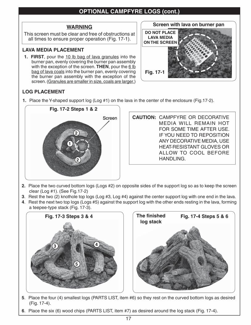
WARNINGThis screen must be clear and free of obstructions at
all times to ensure proper operation (Fig. 17-1).
LAVA MEDIA PLACEMENT1. FIRST, pour the 10 lb bag of lava granules into the
burner pan, evenly covering the burner pan assembly with the exception of the screen. THEN, pour the 6 lb bag of lava coals into the burner pan, evenly covering the burner pan assembly with the exception of the screen. (Granules are smaller in size, coals are larger.)
Screen with lava on burner pan
DO NOT PLACELAVA MEDIA
ON THE SCREEN
CAUTION: CAMPFYRE OR DECORATIVE MEDIA WILL REMAIN HOT FOR SOME TIME AFTER USE. IF YOU NEED TO REPOSITION ANY DECORATIVE MEDIA, USE HEAT-RESISTANT GLOVES OR ALLOW TO COOL BEFORE HANDLING.
1. Place the Y-shaped support log (Log #1) on the lava in the center of the enclosure (Fig.17- 2).
2. Place the two curved bottom logs (Logs #2) on opposite sides of the support log so as to keep the screen clear (Log #1). (See Fig.17- 2)
3. Rest the two (2) knothole top logs (Log #3, Log #4) against the center support log with one end in the lava.4. Rest the next two top logs (Logs #5) against the support log with the other ends resting in the lava, forming
a teepee-type stack (Fig. 17- 3).
5. Place the four (4) smallest logs (PARTS LIST, item #6) so they rest on the curved bottom logs as desired (Fig. 17- 4).
6. Place the six (6) wood chips (PARTS LIST, item #7) as desired around the log stack (Fig. 17- 4).
1
2
2
Fig. 17-2 Steps 1 & 2
Fig. 17- 3 Steps 3 & 4 Fig. 17- 4 Steps 5 & 6
Fig. 17-1
Screen
43
5
OPTIONAL CAMPFYRE LOGS (cont.)
LOG PLACEMENT
1111111111
22222222222222
2222222222222222
Scre
1
2
2
Screen
43
5
18
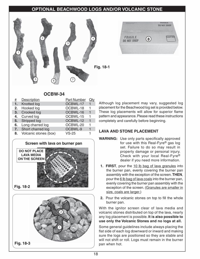
# Description Part Number Qty1. Knotted log OCBWL-17 12. Hooked log OCBWL-18 13. Crooked log OCBWL-16 14. Curved log OCBWL-15 15. Stripped log OCBWL-12 16. Long charred log OCBWL-20 17. Short charred log OCBWL-9 18. Volcanic stones (box) VS-25 1
Fig. 18-1
1
3
7
4
5
2
6
Although log placement may vary, suggested log placement for the Beachwood log set is provided below. These log placements will allow for superior fl ame pattern and appearance. Please read these instructions completely and carefully before beginning.
LAVA AND STONE PLACEMENT
WARNING: Use only parts specifi cally approved for use with this Real-Fyre® gas log set. Failure to do so may result in property damage or personal injury. Check with your local Real-Fyre ® dealer if you need more information.
1. FIRST, pour the 10 lb bag of lava granules into the burner pan, evenly covering the burner pan assembly with the exception of the screen. THEN, pour the 6 lb bag of lava coals into the burner pan, evenly covering the burner pan assembly with the exception of the screen. (Granules are smaller in size, coals are larger.)
2. Pour the volcanic stones on top to fi ll the whole burner pan.
With the ignitor screen clear of lava media and volcanic stones distributed on top of the lava, nearly any log placement is possible. It is also possible to use only the Volcanic Stones and no logs at all.
Some general guidelines include always placing the fl at side of each log downward or inward and making sure the logs are positioned so they are stable and will not shift or roll. Logs must remain in the burner pan when hot.Fig. 18-3
1
2
Fig. 18-2
8
Screen with lava on burner pan
DO NOT PLACELAVA MEDIA
ON THE SCREEN
OPTIONAL BEACHWOOD LOGS AND/OR VOLCANIC STONE
OCBW-34
1
2
11111111111111
22222222222222222
1
2
19
5
3
4
6
7
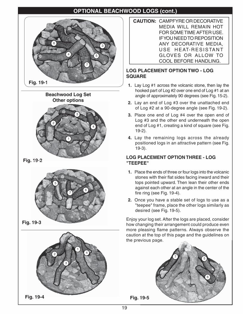
LOG PLACEMENT OPTION TWO - LOG SQUARE
1. Lay Log #1 across the volcanic stone, then lay the hooked part of Log #2 over one end of Log #1 at an angle of approximately 90 degrees (see Fig. 15-2).
2. Lay an end of Log #3 over the unattached end of Log #2 at a 90-degree angle (see Fig. 19-2).
3. Place one end of Log #4 over the open end of Log #3 and the other end underneath the open end of Log #1, creating a kind of square (see Fig. 19-2).
4. Lay the remaining logs across the already positioned logs in an attractive pattern (see Fig. 19-3).
LOG PLACEMENT OPTION THREE - LOG "TEEPEE"
1. Place the ends of three or four logs into the volcanic stones with their fl at sides facing inward and their tops pointed upward. Then lean their other ends against each other at an angle in the center of the fi re ring (see Fig. 19-4).
2. Once you have a stable set of logs to use as a "teepee" frame, place the other logs similarly as desired (see Fig. 19-5).
Enjoy your log set. After the logs are placed, consider how changing their arrangement could produce even more pleasing fl ame patterns. Always observe the caution at the top of this page and the guidelines on the previous page.
CAUTION: CAMPFYRE OR DECORATIVE MEDIA WILL REMAIN HOT FOR SOME TIME AFTER USE. IF YOU NEED TO REPOSITION ANY DECORATIVE MEDIA, U S E H E AT- R E S I S TA N T GLOVES OR ALLOW TO COOL BEFORE HANDLING.
Beachwood Log SetOther options
Fig. 19-2
1
24
3
Fig. 19-3
5
67
Fig. 19-4
1
2
3
4
Fig. 19-5
5
6
7
Fig. 19-1
OPTIONAL BEACHWOOD LOGS (cont.)
55555555555555
3333333333
4444444444444
666666666666
7777777777777777
Fig. 19-1
p
19-2
1111111111
2222222222224444444444444
333333333333
19-3
55555555555555
66666666666777777777
Fig 19 4
1111111111
222222222222222
333333333
444444444444
vious page.
19-5
55555555555
6666666666666666
77777777777777777
5
3
4
6
7
1
24
3
5
3
4
6
7
1
24
3
5
67
1
2
3
4
5
6
7
20
Fig. 20-2
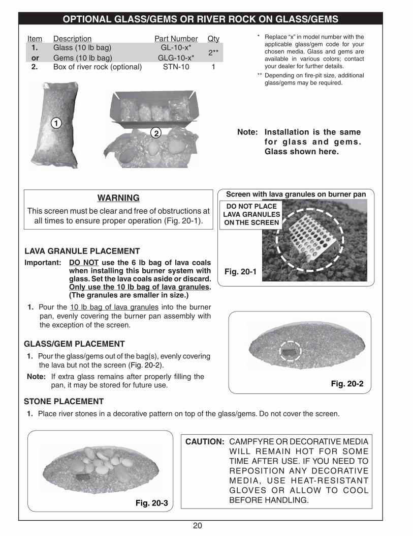
WARNINGThis screen must be clear and free of obstructions at
all times to ensure proper operation (Fig. 20-1).
LAVA GRANULE PLACEMENTImportant: DO NOT use the 6 lb bag of lava coals
when installing this burner system with glass. Set the lava coals aside or discard. Only use the 10 lb bag of lava granules. (The granules are smaller in size.)
1. Pour the 10 lb bag of lava granules into the burner pan, evenly covering the burner pan assembly with the exception of the screen.
Screen with lava granules on burner pan
DO NOT PLACELAVA GRANULES ON THE SCREEN
Fig. 20-1
Item Description Part Number Qty1.or
Glass (10 lb bag)Gems (10 lb bag)
GL-10-x*GLG-10-x*
2**
2. Box of river rock (optional) STN-10 1
2
Fig. 20-3
CAUTION: CAMPFYRE OR DECORATIVE MEDIA WILL REMAIN HOT FOR SOME TIME AFTER USE. IF YOU NEED TO REPOSITION ANY DECORATIVE MEDIA, USE HEAT-RESISTANT GLOVES OR ALLOW TO COOL BEFORE HANDLING.
* Replace “x” in model number with the applicable glass/gem code for your chosen media. Glass and gems are available in various colors; contact your dealer for further details.
** Depending on fi re-pit size, additional glass/gems may be required.
1
OPTIONAL GLASS/GEMS OR RIVER ROCK ON GLASS/GEMS
GLASS/GEM PLACEMENT1. Pour the glass/gems out of the bag(s), evenly covering
the lava but not the screen (Fig. 20- 2).
Note: If extra glass remains after properly fi lling the pan, it may be stored for future use.
STONE PLACEMENT1. Place river stones in a decorative pattern on top of the glass/gems. Do not cover the screen.
Note: Installation is the same for glass and gems. Glass shown here.
21
+
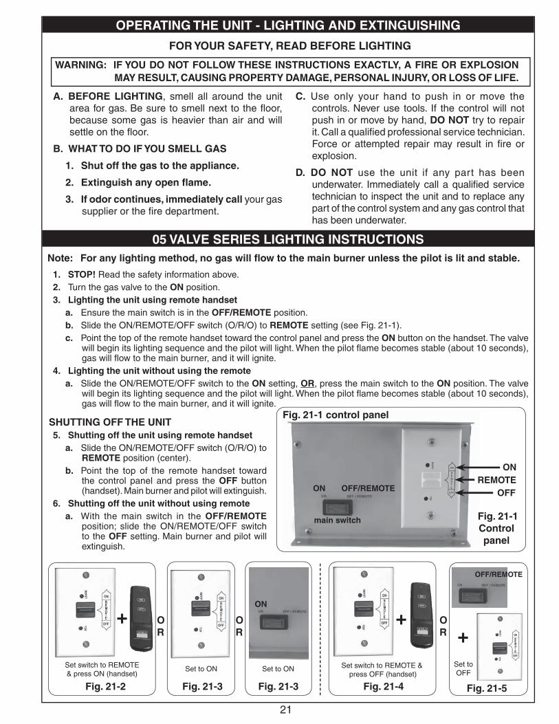
1. STOP! Read the safety information above.2. Turn the gas valve to the ON position.3. Lighting the unit using remote handset
a. Ensure the main switch is in the OFF/REMOTE position.b. Slide the ON/REMOTE/OFF switch (O/R/O) to REMOTE setting (see Fig. 21-1). c. Point the top of the remote handset toward the control panel and press the ON button on the handset. The valve
will begin its lighting sequence and the pilot will light. When the pilot fl ame becomes stable (about 10 seconds), gas will fl ow to the main burner, and it will ignite.
4. Lighting the unit without using the remotea. Slide the ON/REMOTE/OFF switch to the ON setting, OR, press the main switch to the ON position. The valve
will begin its lighting sequence and the pilot will light. When the pilot fl ame becomes stable (about 10 seconds), gas will fl ow to the main burner, and it will ignite.
SHUTTING OFF THE UNIT 5. Shutting off the unit using remote handset
a. Slide the ON/REMOTE/OFF switch (O/R/O) to REMOTE position (center).
b. Point the top of the remote handset toward the control panel and press the OFF button (handset). Main burner and pilot will extinguish.
6. Shutting off the unit without using remotea. With the main switch in the OFF/REMOTE
position; slide the ON/REMOTE/OFF switch to the OFF setting. Main burner and pilot will extinguish.
Set switch to REMOTE & press ON (handset)
Set to ON
Note: For any lighting method, no gas will fl ow to the main burner unless the pilot is lit and stable.
OR
Set switch to REMOTE & press OFF (handset)
Set to OFF
+
Fig. 21-2 Fig. 21-3 Fig. 21-4 Fig. 21-5
OPERATING THE UNIT - LIGHTING AND EXTINGUISHING
05 VALVE SERIES LIGHTING INSTRUCTIONS
A. BEFORE LIGHTING, smell all around the unit area for gas. Be sure to smell next to the fl oor, because some gas is heavier than air and will settle on the fl oor.
B. WHAT TO DO IF YOU SMELL GAS
1. Shut off the gas to the appliance.
2. Extinguish any open fl ame.
3. If odor continues, immediately call your gas supplier or the fi re department.
C. Use only your hand to push in or move the controls. Never use tools. If the control will not push in or move by hand, DO NOT try to repair it. Call a qualifi ed professional service technician. Force or attempted repair may result in fi re or explosion.
D. DO NOT use the unit if any part has been underwater. Immediately call a qualifi ed service technician to inspect the unit and to replace any part of the control system and any gas control that has been underwater.
FOR YOUR SAFETY, READ BEFORE LIGHTING
WARNING: IF YOU DO NOT FOLLOW THESE INSTRUCTIONS EXACTLY, A FIRE OR EXPLOSION MAY RESULT, CAUSING PROPERTY DAMAGE, PERSONAL INJURY, OR LOSS OF LIFE.
OFFREMOTE
ON
Fig. 21-1 Control panel
ON OFF/REMOTE
main switch
ON
OFF/REMOTE
+OR
OR
Set to ON
Fig. 21-3
Fig. 21-1 control panel
22
+
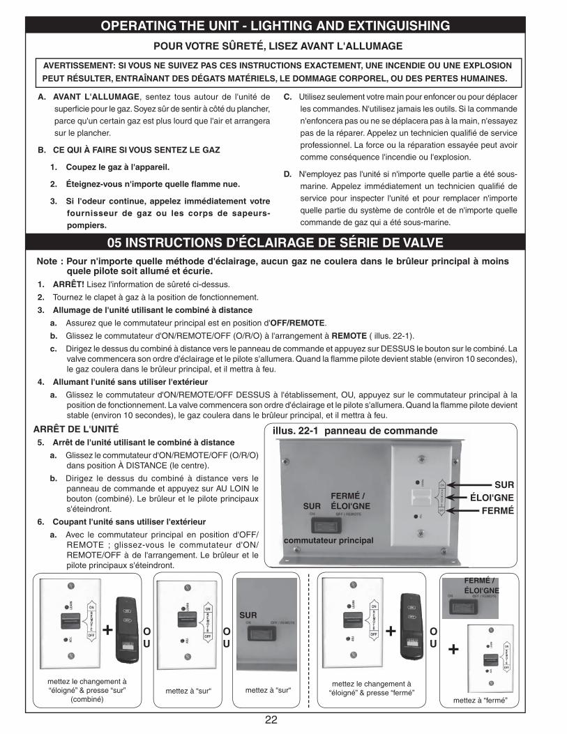
1. ARRÊT! Lisez l'information de sûreté ci-dessus.
2. Tournez le clapet à gaz à la position de fonctionnement.
3. Allumage de l'unité utilisant le combiné à distance
a. Assurez que le commutateur principal est en position d'OFF/REMOTE.
b. Glissez le commutateur d'ON/REMOTE/OFF (O/R/O) à l'arrangement à REMOTE ( illus. 22-1).
c. Dirigez le dessus du combiné à distance vers le panneau de commande et appuyez sur DESSUS le bouton sur le combiné. La valve commencera son ordre d'éclairage et le pilote s'allumera. Quand la fl amme pilote devient stable (environ 10 secondes), le gaz coulera dans le brûleur principal, et il mettra à feu.
4. Allumant l'unité sans utiliser l'extérieur
a. Glissez le commutateur d'ON/REMOTE/OFF DESSUS à l'établissement, OU, appuyez sur le commutateur principal à la position de fonctionnement. La valve commencera son ordre d'éclairage et le pilote s'allumera. Quand la fl amme pilote devient stable (environ 10 secondes), le gaz coulera dans le brûleur principal, et il mettra à feu.
ARRÊT DE L'UNITÉ 5. Arrêt de l'unité utilisant le combiné à distance
a. Glissez le commutateur d'ON/REMOTE/OFF (O/R/O) dans position À DISTANCE (le centre).
b. Dirigez le dessus du combiné à distance vers le panneau de commande et appuyez sur AU LOIN le bouton (combiné). Le brûleur et le pilote principaux s'éteindront.
6. Coupant l'unité sans utiliser l'extérieur
a. Avec le commutateur principal en position d'OFF/REMOTE ; glissez-vous le commutateur d'ON/REMOTE/OFF à de l'arrangement. Le brûleur et le pilote principaux s'éteindront.
Note : Pour n'importe quelle méthode d'éclairage, aucun gaz ne coulera dans le brûleur principal à moins quele pilote soit allumé et écurie.
OU
+
OPERATING THE UNIT - LIGHTING AND EXTINGUISHING
05 INSTRUCTIONS D'ÉCLAIRAGE DE SÉRIE DE VALVE
A. AVANT L'ALLUMAGE, sentez tous autour de l'unité de superfi cie pour le gaz. Soyez sûr de sentir à côté du plancher, parce qu'un certain gaz est plus lourd que l'air et arrangera sur le plancher.
B. CE QUI À FAIRE SI VOUS SENTEZ LE GAZ
1. Coupez le gaz à l'appareil.
2. Éteignez-vous n'importe quelle fl amme nue.
3. Si l'odeur continue, appelez immédiatement votre fournisseur de gaz ou les corps de sapeurs-pompiers.
C. Utilisez seulement votre main pour enfoncer ou pour déplacer les commandes. N'utilisez jamais les outils. Si la commande n'enfoncera pas ou ne se déplacera pas à la main, n'essayez pas de la réparer. Appelez un technicien qualifi é de service professionnel. La force ou la réparation essayée peut avoir comme conséquence l'incendie ou l'explosion.
D. N'employez pas l'unité si n'importe quelle partie a été sous-marine. Appelez immédiatement un technicien qualifi é de service pour inspecter l'unité et pour remplacer n'importe quelle partie du système de contrôle et de n'importe quelle commande de gaz qui a été sous-marine.
POUR VOTRE SÛRETÉ, LISEZ AVANT L'ALLUMAGE
AVERTISSEMENT: SI VOUS NE SUIVEZ PAS CES INSTRUCTIONS EXACTEMENT, UNE INCENDIE OU UNE EXPLOSION
PEUT RÉSULTER, ENTRAÎNANT DES DÉGATS MATÉRIELS, LE DOMMAGE CORPOREL, OU DES PERTES HUMAINES.
SUR
+OU
OU
FERMÉÉLOI'GNE
SUR
illus. 22-1 panneau de commande
SUR
commutateur principal
FERMÉ / ÉLOI'GNE
mettez le changement à “éloigné” & presse “sur”
(combiné)mettez à “sur“ mettez à “sur“
mettez le changement à “éloigné” & presse “fermé”
mettez à “fermé”
FERMÉ / ÉLOI'GNE
23
+
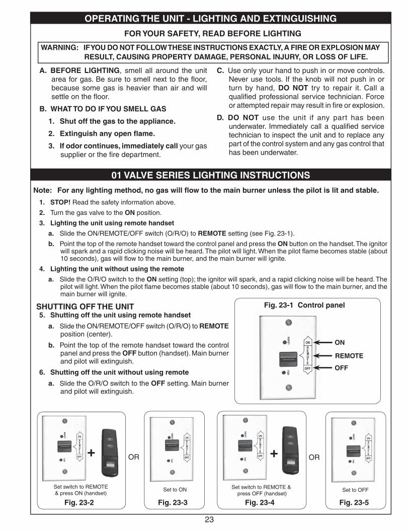
1. STOP! Read the safety information above.
2. Turn the gas valve to the ON position.
3. Lighting the unit using remote handset
a. Slide the ON/REMOTE/OFF switch (O/R/O) to REMOTE setting (see Fig. 23-1).
b. Point the top of the remote handset toward the control panel and press the ON button on the handset. The ignitor will spark and a rapid clicking noise will be heard. The pilot will light. When the pilot fl ame becomes stable (about 10 seconds), gas will fl ow to the main burner, and the main burner will ignite.
4. Lighting the unit without using the remote
a. Slide the O/R/O switch to the ON setting (top); the ignitor will spark, and a rapid clicking noise will be heard. The pilot will light. When the pilot fl ame becomes stable (about 10 seconds), gas will fl ow to the main burner, and the main burner will ignite.
SHUTTING OFF THE UNIT 5. Shutting off the unit using remote handset
a. Slide the ON/REMOTE/OFF switch (O/R/O) to REMOTE position (center).
b. Point the top of the remote handset toward the control panel and press the OFF button (handset). Main burner and pilot will extinguish.
6. Shutting off the unit without using remote
a. Slide the O/R/O switch to the OFF setting. Main burner and pilot will extinguish.
OR
Set switch to REMOTE & press ON (handset)
Set to ON
Fig. 23-1 Control panel
Note: For any lighting method, no gas will fl ow to the main burner unless the pilot is lit and stable.
OR
Set switch to REMOTE & press OFF (handset)
Set to OFF
+
Fig. 23-2 Fig. 23-3 Fig. 23-4 Fig. 23-5
OPERATING THE UNIT - LIGHTING AND EXTINGUISHING
01 VALVE SERIES LIGHTING INSTRUCTIONS
A. BEFORE LIGHTING, smell all around the unit area for gas. Be sure to smell next to the fl oor, because some gas is heavier than air and will settle on the fl oor.
B. WHAT TO DO IF YOU SMELL GAS
1. Shut off the gas to the appliance.
2. Extinguish any open fl ame.
3. If odor continues, immediately call your gas supplier or the fi re department.
C. Use only your hand to push in or move controls. Never use tools. If the knob will not push in or turn by hand, DO NOT try to repair it. Call a qualifi ed professional service technician. Force or attempted repair may result in fi re or explosion.
D. DO NOT use the unit if any part has been underwater. Immediately call a qualifi ed service technician to inspect the unit and to replace any part of the control system and any gas control that has been underwater.
FOR YOUR SAFETY, READ BEFORE LIGHTING
WARNING: IF YOU DO NOT FOLLOW THESE INSTRUCTIONS EXACTLY, A FIRE OR EXPLOSION MAY RESULT, CAUSING PROPERTY DAMAGE, PERSONAL INJURY, OR LOSS OF LIFE.
OFF
REMOTE
ON
24
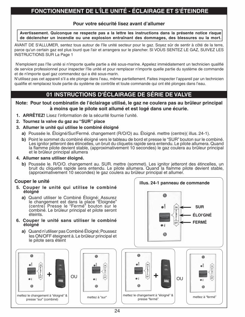
Note: Pour tout combinatin de l’éclairage utilisé, le gaz ne coulera pas au brûleur principal à moins que le pilote soit allumé et est logé dans une écurie.
1. ARRÊTEZ! Lisez l’information de la sécurité fournie l’unité.2. Tournez la valve du gaz au “SUR” place3. Allumer le unité qui utilise le combiné éloigné
a) Poussée le. Éloigné/Sur/Fermé. changement (R/O/O) au. Éloigné. mettre (centre)( illus. 24-1).b) Point le sommet du combiné éloigné vers le tableau de bord et presse le “SUR” bouton sur le combiné.
Les ignitor jetteront des étincelles, un bruit du cliquetis rapide sera entendu. Le pilote allumera. Quand la fl amme pilote devient stable, (approximativement 10 secondes) le gaz coulera au brûleur principal et le brûleur principal allumera
4. Allumer sans utiliser éloigné.b) Poussée le. R/O/O. changement au. SUR. mettre (sommet). Les ignitor jetteront des étincelles, un
bruit du cliquetis rapide sera entendu. Le pilote allumera. Quand la fl amme pilote devient stable, (approximativement 10 secondes) le gaz coulera au brûleur principal et allumer.
OU
mettez à “sur“
01 INSTRUCTIONS D'ÉCLAIRAGE DE SÉRIE DE VALVE
mettez le changement à “éloigné” & presse “sur” (combiné)
illus. 24-1 panneau de commande
AVANT DE S'ALLUMER, sentez tous autour de l'île unité secteur pour le gaz. Soyez sûr de sentir à côté de la terre, parce qu'un certain gaz est plus lourd que l'air et arrangera sur le plancher. SI VOUS SENTEZ LE GAZ, SUIVEZ LES INSTRUCTIONS SUR La Page 1
N'emploient pas l'île unité si n'importe quelle partie a été sous-marine. Appelez immédiatement un technicien qualifi é de service professionnel pour inspecter l'île unité et pour remplacer n'importe quelle partie du système de commande et de n'importe quel gaz commandez qui a été sous-marin.N’utilisez pas cet appareil s’il a ete plonge dans l’eau, même partiellement. Faites inspecter l’appareil par un technicien qualifi e et remplacez toute partie du système de contrôle et toute commande qui ont été plonges dans l’eau.
Pour votre sécurité lisez avant d’allumer
FONCTIONNEMENT DE L'ÎLE UNITÉ - ÉCLAIRAGE ET S'ÉTEINDRE
Avertissement. Quiconque ne respecte pas a la lettre les instructions dans la présente notice risque de déclencher un incendie ou une explosion entraînant des dommages, des blessures ou la mort.
OU
mettez le changement à “éloigné” & presse “fermé”
mettez à “fermé”
Couper le unité5. Couper le unité qui utilise le combiné
éloigné a) Quand utiliser le Combiné Éloigné; Assurez
le changement est dans la place “Éloignée” (centre) Presse le “Fermé” bouton sur le combiné. Le brûleur principal et pilote seront éteints.
6. Couper le unité sans utiliser le combiné éloigné
a) Quand n’utiliser pas Combiné Éloigné; Poussez les ON/OFF éteignent à. Le brûleur principal et le pilote sera éteint
+ +
SUR
FERMÉ
ÉLOl'GNÉ
25
A. BEFORE LIGHTING, smell all around the unit area for gas. Be sure to smell next to the fl oor, because some gas is heavier than air and will settle on the fl oor.
B. WHAT TO DO IF YOU SMELL GAS
1. Shut off the gas to the appliance.
2. Extinguish any open fl ame.
3. If odor continues, immediately call your gas supplier or the fi re department.
C. Use only your hand to push in or turn the gas control knob. Never use tools. If the knob will not push in or turn by hand, DO NOT try to repair it. Call a qualifi ed professional service technician. Force or attempted repair may result in fi re or explosion.
D. DO NOT use the unit if any part has been underwater. Immediately call a qualifi ed service technician to inspect the unit and to replace any part of the control system and any gas control that has been underwater.
FOR YOUR SAFETY, READ BEFORE LIGHTING
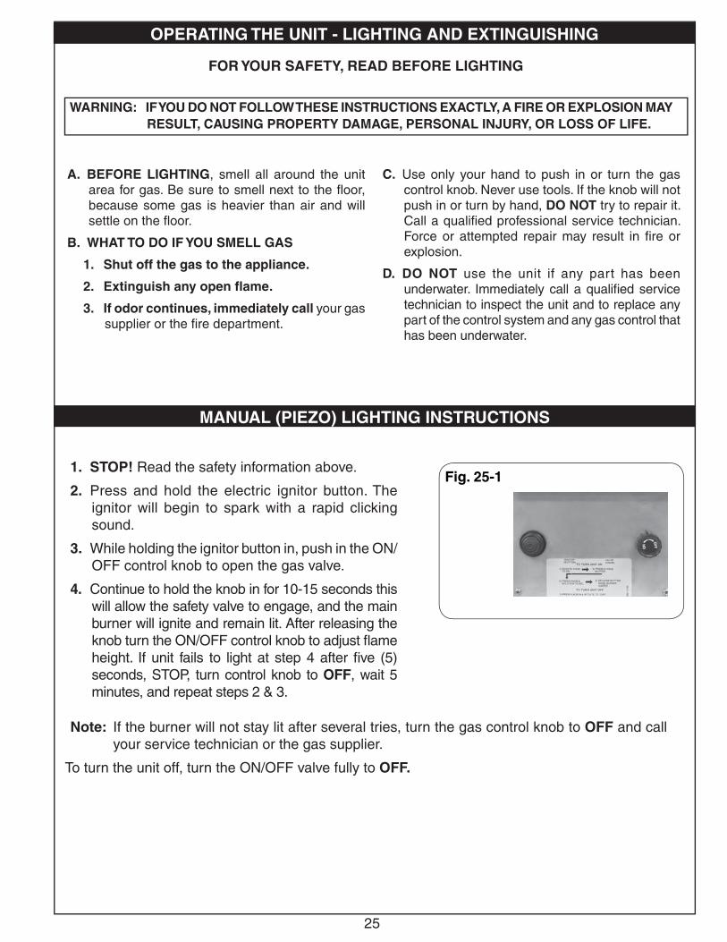
1. STOP! Read the safety information above.
2. Press and hold the electric ignitor button. The ignitor will begin to spark with a rapid clicking sound.
3. While holding the ignitor button in, push in the ON/OFF control knob to open the gas valve.
4. Continue to hold the knob in for 10-15 seconds this will allow the safety valve to engage, and the main burner will ignite and remain lit. After releasing the knob turn the ON/OFF control knob to adjust fl ame height. If unit fails to light at step 4 after fi ve (5) seconds, STOP, turn control knob to OFF, wait 5 minutes, and repeat steps 2 & 3.
Note: If the burner will not stay lit after several tries, turn the gas control knob to OFF and call your service technician or the gas supplier.
To turn the unit off, turn the ON/OFF valve fully to OFF.
Fig. 25-1
OPERATING THE UNIT - LIGHTING AND EXTINGUISHING
MANUAL (PIEZO) LIGHTING INSTRUCTIONS
WARNING: IF YOU DO NOT FOLLOW THESE INSTRUCTIONS EXACTLY, A FIRE OR EXPLOSION MAY RESULT, CAUSING PROPERTY DAMAGE, PERSONAL INJURY, OR LOSS OF LIFE.
26
A. AVANT DE S’ALLUMER, sentez tous autour du secteur extérieur de feu de camp pour le gaz. Soyez sûr de sentir à côté du plancher, parce qu’un certain gaz est plus lourd que l’air et arrangera sur le plancher.
B. CE QUI À FAIRE SI VOUS SENTEZ LE GAZ
1. Coupez le gaz à l’appareil.
2. Éteignez-vous n’importe quelle flamme nue.
3. Si l’odeur continue, appelez immédiatement votre fournisseur de gaz ou le département de feu.
C. Utilisez seulement votre main pour enfoncer ou pour tourner le bouton de commande de gaz. N’utilisez jamais les outils. Si le bouton n’enfoncera pas ou ne tournera pas à la main, n’essayez pas de le réparer. Appelez un technicien qualifi é de service professionnel. La force ou la réparation essayée peut avoir comme conséquence l’incendie ou l’explosion.
D. N’employez pas le feu de camp extérieur si n’importe quelle partie a été sous-marine. Appelez immédiatement un technicien qualifi é de service pour inspecter le feu de camp extérieur et pour remplacer n’importe quelle partie du système de commande et de n’importe quelle commande de gaz qui a été sous-marine.
AVERTISSEMENTSI VOUS NE SUIVEZ PAS CES INSTRUCTIONS EXACTEMENT, UNE INCENDIE OU UNE EXPLOSION PEUT RÉSULTER, ENTRAÎNANT DES DÉGATS
MATÉRIELS, DES BLESSURES, OU LA PERTE DE LA VIE.
POUR VOTRE SÛRETÉ, LISEZ AVANT DE S’ALLUMER
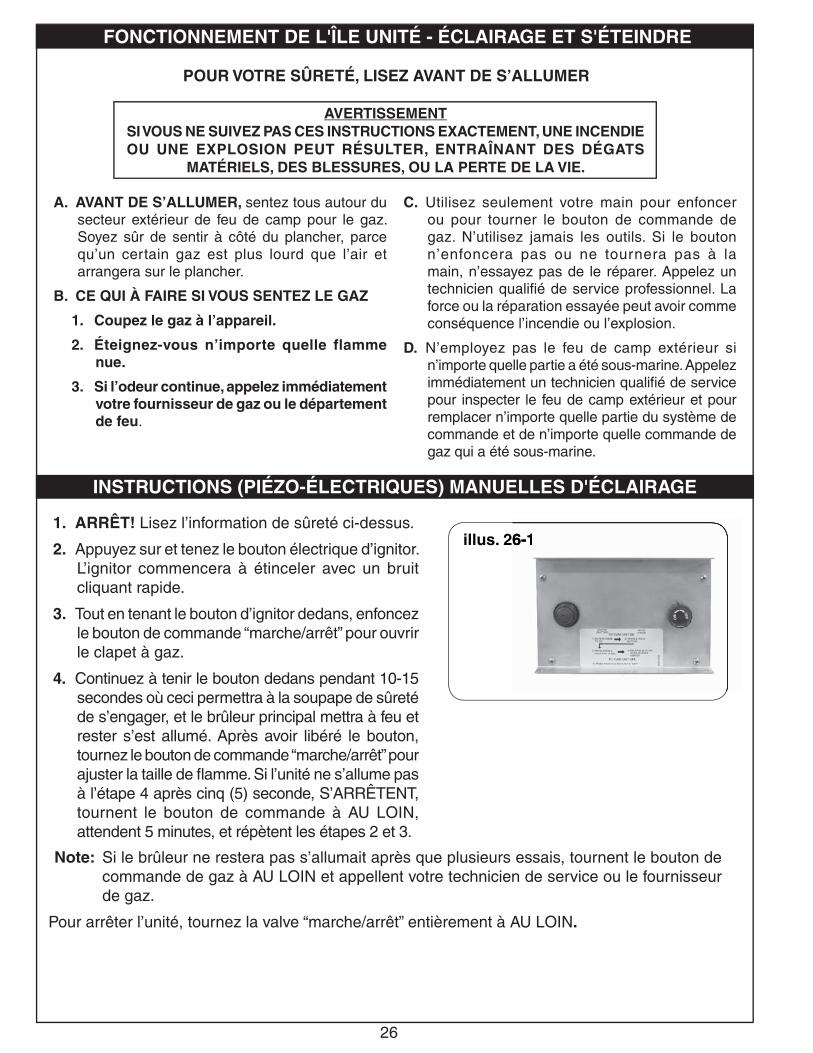
1. ARRÊT! Lisez l’information de sûreté ci-dessus.
2. Appuyez sur et tenez le bouton électrique d’ignitor. L’ignitor commencera à étinceler avec un bruit cliquant rapide.
3. Tout en tenant le bouton d’ignitor dedans, enfoncez le bouton de commande “marche/arrêt” pour ouvrir le clapet à gaz.
4. Continuez à tenir le bouton dedans pendant 10-15 secondes où ceci permettra à la soupape de sûreté de s’engager, et le brûleur principal mettra à feu et rester s’est allumé. Après avoir libéré le bouton, tournez le bouton de commande “marche/arrêt” pour ajuster la taille de fl amme. Si l’unité ne s’allume pas à l’étape 4 après cinq (5) seconde, S’ARRÊTENT, tournent le bouton de commande à AU LOIN, attendent 5 minutes, et répètent les étapes 2 et 3.
Note: Si le brûleur ne restera pas s’allumait après que plusieurs essais, tournent le bouton de commande de gaz à AU LOIN et appellent votre technicien de service ou le fournisseur de gaz.
Pour arrêter l’unité, tournez la valve “marche/arrêt” entièrement à AU LOIN.
INSTRUCTIONS (PIÉZO-ÉLECTRIQUES) MANUELLES D'ÉCLAIRAGE
FONCTIONNEMENT DE L'ÎLE UNITÉ - ÉCLAIRAGE ET S'ÉTEINDRE
illus. 26-16-6-11
27
A. BEFORE LIGHTING, smell all around the unit area for gas. Be sure to smell next to the fl oor, because some gas is heavier than air and will settle on the fl oor.
B. WHAT TO DO IF YOU SMELL GAS
1. Shut off the gas to the appliance.
2. Extinguish any open fl ame.
3. If odor continues, immediately call your gas supplier or the fi re department.
C. Use only your hand to push in or turn the gas control knob. Never use tools. If the knob will not push in or turn by hand, DO NOT try to repair it. Call a qualifi ed professional service technician. Force or attempted repair may result in fi re or explosion.
FOR YOUR SAFETY, READ BEFORE LIGHTING
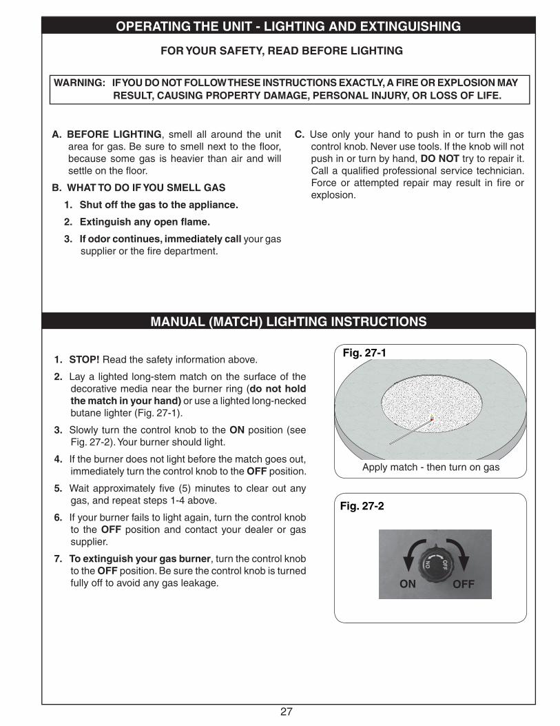
1. STOP! Read the safety information above.
2. Lay a lighted long-stem match on the surface of the decorative media near the burner ring (do not hold the match in your hand) or use a lighted long-necked butane lighter (Fig. 27-1).
3. Slowly turn the control knob to the ON position (see Fig. 27-2). Your burner should light.
4. If the burner does not light before the match goes out, immediately turn the control knob to the OFF position.
5. Wait approximately fi ve (5) minutes to clear out any gas, and repeat steps 1-4 above.
6. If your burner fails to light again, turn the control knob to the OFF position and contact your dealer or gas supplier.
7. To extinguish your gas burner, turn the control knob to the OFF position. Be sure the control knob is turned fully off to avoid any gas leakage.
OPERATING THE UNIT - LIGHTING AND EXTINGUISHING
MANUAL (MATCH) LIGHTING INSTRUCTIONS
WARNING: IF YOU DO NOT FOLLOW THESE INSTRUCTIONS EXACTLY, A FIRE OR EXPLOSION MAY RESULT, CAUSING PROPERTY DAMAGE, PERSONAL INJURY, OR LOSS OF LIFE.
Fig. 27-1
Apply match - then turn on gas
OFFON
Fig. 27-2
28
A. AVANT L'ALLUMAGE, sentez tous autour de l'unité de superfi cie pour le gaz. Soyez sûr de sentir à côté du plancher, parce qu'un certain gaz est plus lourd que l'air et arrangera sur le plancher.
B. CE QUI À FAIRE SI VOUS SENTEZ LE GAZ
1. Coupez le gaz à l'appareil.
2. Éteignez-vous n'importe quelle fl amme nue.
3. Éteignez-vous n'importe quelle fl amme nue. Si l'odeur continue, appelez immédiatement votre fournisseur de gaz ou les corps de sapeurs-pompiers.
C. Utilisez seulement votre main pour enfoncer ou pour tourner le bouton de commande de gaz. N’utilisez jamais les outils. Si le bouton n’enfoncera pas ou ne tournera pas à la main, n’essayez pas de le réparer. Appelez un technicien qualifi é de service professionnel. La force ou la réparation essayée peut avoir comme conséquence l’incendie ou l’explosion.
POUR VOTRE SÛRETÉ, LISEZ AVANT L'ALLUMAGE
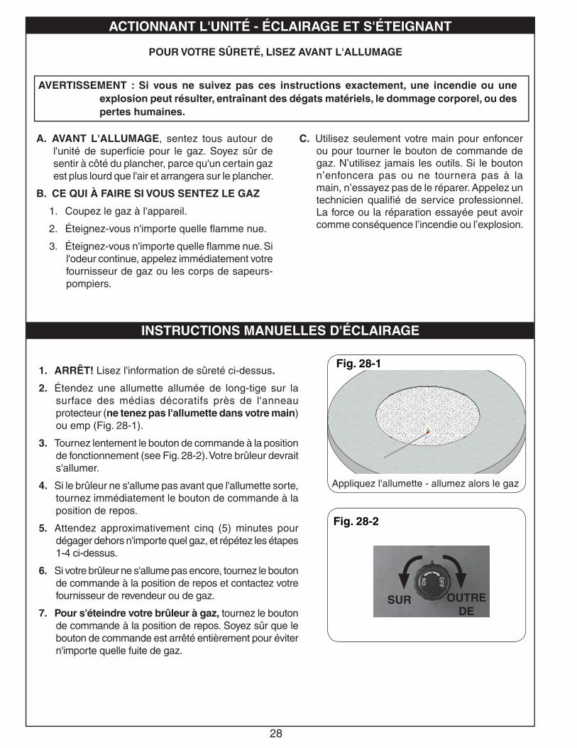
1. ARRÊT! Lisez l'information de sûreté ci-dessus.
2. Étendez une allumette allumée de long-tige sur la surface des médias décoratifs près de l'anneau protecteur (ne tenez pas l'allumette dans votre main) ou emp (Fig. 28-1).
3. Tournez lentement le bouton de commande à la position de fonctionnement (see Fig. 28-2). Votre brûleur devrait s'allumer.
4. Si le brûleur ne s'allume pas avant que l'allumette sorte, tournez immédiatement le bouton de commande à la position de repos.
5. Attendez approximativement cinq (5) minutes pour dégager dehors n'importe quel gaz, et répétez les étapes 1-4 ci-dessus.
6. Si votre brûleur ne s'allume pas encore, tournez le bouton de commande à la position de repos et contactez votre fournisseur de revendeur ou de gaz.
7. Pour s'éteindre votre brûleur à gaz, tournez le bouton de commande à la position de repos. Soyez sûr que le bouton de commande est arrêté entièrement pour éviter n'importe quelle fuite de gaz.
ACTIONNANT L'UNITÉ - ÉCLAIRAGE ET S'ÉTEIGNANT
INSTRUCTIONS MANUELLES D'ÉCLAIRAGE
AVERTISSEMENT : Si vous ne suivez pas ces instructions exactement, une incendie ou une explosion peut résulter, entraînant des dégats matériels, le dommage corporel, ou des pertes humaines.
Fig. 28-1
Fig. 28-2
OUTRE DE
SUR
Appliquez l'allumette - allumez alors le gaz
29
Each installation site for any unit presents its own unique combustion environment. Specifi c factors such as weather, wind currents, yard debris, altitude, drafts, the size of the surrounding area, all have an infl uence on the proper operation of the unit. A normally operating unit will demonstrate the following characteristics:
a) A lively, realistic yellow fl ame,
b) Odor-free.
• If the fl ame is not clean (identifi able by excessive sooting on the decorative media), refer to the CLEANING AND MAINTENANCE section below.
CAUTIONHOT DURING OPERATION AND AFTER USE. Children must be supervised when in the vicinity of this appliance. Serious injury may occur! Children must be alerted to the hazard of high surface temperatures and should stay away to avoid burns or clothing ignition.
A. Always shut off the gas to the unit while performing service work.
B. Allow the unit to cool before servicing.
C. The unit should be inspected regularly. Excessive debris can build up on this unit from leaves, dirt, or other debris. It is critical that all control components, burners, burner screen, and vent openings be kept clean and free of all obstructions.
Keep the vent openings at the base of the enclosure clean and free of obstructions at all times.
Keep the screen on the burner pan clean and free of decorative media and other items that may cause obstruction.
D. The burner assembly must be replaced prior to the unit being put into operation if it is evident that the burner is damaged. Contact your local dealer for replacement parts.
E. Periodically perform visual checks of the burner fl ames, and pilot fl ames (if applicable). The burner fl ames should be blue at the base with a combination of blue/yellow at the body and tips. The pilot (if applicable) should be a steady fl ame, touching the electrode/thermocouple. Contact a qualifi ed service person for maintenance.
F. Any guard or other protective device removed for servicing the appliance shall be replaced prior to operating the appliance.
OPERATION
CLEANING & MAINTENANCE
30Robert H. Peterson Co. • 14724 East Proctor Avenue • City of Industry, CA 91746
Quality Check Date:_________________Burner Orifi ce Nat. L.P. Leak Test: ___________ Model#: ___________________
Main: ____ ____ Burn Test: ___________ Serial#: ___________________
Gas Type: Nat. / L.P. Inspector: ___________________
A COPY OF YOUR SALES SLIP FOR PROOF OF PURCHASE IS REQUIRED
This warranty applies to the original purchaser for products which are installed in the United States or Canada and which are operated and maintained as intended for single family residential usage. This warranty is valid only with proof of purchase, shall commence on the date of purchase, and shall terminate (both as to original and any replacement products) on the anniversary date of the original purchase of the product stated on the above schedules.
This warranty covers defects in material and workmanship. This warranty does not cover parts which become defective as a result of negligence, misuse, use not in compliance with the Owner’s Manual/Installation Instructions, accidental damage, improper handling, improper storage, improper installation, lack of required routine maintenance (as specifi ed in the Owner’s Manual/Installation Instructions), electrical damage, local gas impurities or failure to protect against combustibles. Product must be installed (and gas must be connected) as specifi ed in the Owner’s Manual/Installation Instructions by a qualifi ed professional installer. Modifi cations to products which are not specifi cally authorized will void this warranty. Accessories, parts, valves, remotes, etc. when used must be Peterson products or this warranty is void. Warrantied items will be repaired or replaced at Peterson’s sole discretion. This warranty does not apply to rust, corrosion, oxidation, or discoloration unless the affected part becomes inoperable.
This warranty does not cover labor or labor related charges, except as provided by separate specifi c written programs from the Peterson Co. All repair work must be performed by a qualifi ed professional service person and requires prior approval of Peterson.
Peterson may require the defective product or part to be returned to the factory to determine the cause of failure. Peterson will pay freight charges if the product or part is determined to be defective. This warranty does not cover breakage in shipment from our (Independent) distributor to its customer if the damage is determined to have occurred during that shipment.
This warranty specifi cally excludes liability for indirect, incidental, or consequential damages. Some states and provinces do not allow the exclusion or limitation of incidental or consequential damages, so the above exclusion may not apply to you. This warranty gives you specifi ed legal rights, and you may have other rights that vary from state to state or province.
For additional information regarding this warranty, or to place a warranty claim, contact the R. H. Peterson dealer where the product was purchased.
TO REGISTER YOUR PRODUCT ONLINE GO TO: WWW.RHPETERSON.COM,AND CLICK ON PRODUCT REGISTRATION. THANK YOU FOR YOUR PURCHASE.
AMERICAN FYRE DESIGNS BY R. H. PETERSON CO. LIMITED WARRANTY
Robert H. Peterson Co. (“RHP”) warrants your American Fire Designs product to be free from defects in material and workmanship.
American Fyre Designs (“AFD”) exterior fi re features and accessories (“products”) are warranted for THREE (3) YEARS.
All AFD valves, electrical components, and controls are warranted for ONE (1) YEAR (excluding batteries).
This warranty does not apply to: product damage caused by burning wood or any fuel other than natural gas or propane; or damage or discoloration to product used in high wind conditions.
WARRANTY