Embed Size (px)
Citation preview
1 | P a g e
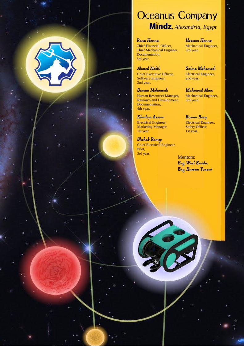
Hossam Hanno: Mechanical Engineer,
3rd year.
Oceanus Company
Rana Hanno: Chief Financial Officer,
Chief Mechanical Engineer,
Documentation,
3rd year.
, Alexandria, Egypt
Salma Mohamed: Electrical Engineer,
2nd year.
Ahmed Nabil: Chief Executive Officer,
Software Engineer,
2nd year.
Mahmoud Alaa: Mechanical Engineer,
3rd year.
Samaa Mohamed: Human Resources Manager,
Research and Development,
Documentation,
4th year.
Rowan Rezq: Electrical Engineer,
Safety Officer,
1st year.
Shehab Ramy: Chief Electrical Engineer,
Pilot,
3rd year.
Khadeja Assem: Electrical Engineer,
Marketing Manager,
1st year.
Mentors:
Eng. Wael Eweda. Eng. Kareem Youssri

2 | P a g e
2016
Table of Contents Acknowledgments ........................................... 3
Abstract ........................................................... 4
Mission Theme ................................................ 5
Mission to Europa ....................................... 5
Mission-Critical Equipment Recovery ......... 5
Forensic Fingerprinting ............................... 5
Deepwater Coral Study ............................... 5
Rigs-to-Reefs ............................................... 6
Strategy .......................................................... 6
1.Design Rational and Vehicle System ............ 7
1.1. Frame .................................................... 7
1.2. Thrusters ............................................... 7
1.3. Degrees of Freedom ............................. 8
1.4. Buoyancy............................................... 8
1.5. Stability ................................................. 9
1.6. Floatation .............................................. 9
1.7. Payloads .............................................. 10
1.7.1. Temperature sensor .................... 10
1.7.2. ‘Netted Box’ ................................ 10
1.8. Manipulator ........................................ 10
2. Electrical ................................................... 11
2.1. Electric canister ................................... 11
2.2. Electric boards .................................... 11
2.3. Sensors ................................................ 12
2.3.1. Pressure sensor: .......................... 12
2.3.2. Temperature sensor: .................. 12
2.3.3. Water detection sensor: ............. 12
2.3.4. Current sensor: ........................... 12
2.4. Controller ............................................ 12
2.5. Camera ................................................ 12
2.5. Lightning ............................................. 13
2.6. Driving Station .................................... 13
3. Tether ....................................................... 13
4. Software ................................................... 14
4. Isolation System ........................................ 14
5. Safety ........................................................ 14
5.1. Safety Philosophy............................... 14
5.2. Safety checklist .................................. 15
5.3. Workshop........................................... 15
5.4. Crew Safety ........................................ 15
5.4. Vehicle Safety .................................... 15
5.4.1. Mechanical wise ......................... 15
5.4.2. Electrical wise ............................. 15
6. Quality Assurance ..................................... 15
6.1. Testing Methods ................................ 15
6.2. Troubleshooting ................................. 16
7. Challenges ................................................. 16
7.1. Non-technical ..................................... 16
7.2. Technical ............................................ 17
8. Lessons Learnt .......................................... 17
8.1. Technical ............................................ 17
8.2. Interpersonal: .................................... 17
9. Future Improvements ............................... 17
9.1. Non- technical .................................... 18
9.2. Technical ............................................ 18
10. Reflections .............................................. 18
11. Teamwork ............................................... 19
12. Project Management .............................. 20
13. References .............................................. 20
14. Media Outreach ...................................... 20
15. Project Costing ........................................ 21
16. Budget ..................................................... 21
17.Appendix .................................................. 22
17.1. System Interconnected Diagram ..... 22
17.2. Motor Comparison Table ................. 23
17.3. Software Flowchart .......................... 24
17.4. Safety Checklist ................................ 24
17.6. Gantt Chart ...................................... 25
17.7. Joystick Configuration ..................... 25
3 | P a g e
2016
Acknowledgments
Oceanus Company had taken huge efforts to accomplish this ROV the way it functions. However, it would not have been possible without the support and help of many individuals and organizations. We would like to extend our sincere gratefulness to all of them.
First of all, we are grateful to the Marine Advanced Technology Education Centre (MATE), the Arab Academy for Science, Technology and Maritime Transport (AASTMT) and Hadath, for giving our company this opportunity to compete in this event.
In addition, we would like to express our gratitude towards our parents for their financial and moral support.
Furthermore, we are highly thankful to Mindz for the technical support, the guidance and constant supervision as well as for the technical and academic support.
We desire to express our sincere gratitude to our mentors Eng. Kareem Youssri and Eng. Wael Eweda for giving us such precious attention and time, as well as teaching us the bases of electronics, mechanics and programming. We could have not achieved what we have reached without their patient guidance, enthusiastic encouragement and useful critiques throughout our company’s journey.
We would like to thank the online newspapers Sout Alomma and Al Barkeya AlTunseya for their media sponsorship. Also, we would like to thank Oxy Dive for donating $100 when we won the regional competition. We extend our gratitude to Al Alameya Company for helping us in laser-cutting our polyethylene sheets.
We would like to thank Excellent Threads Company for being generous enough to donate t-shirts for the team members.
We would like to say thank you to Maha Moustafa for giving us really helpful advice for the technical writing. We would like to also thank the members of Torbini team for their technical support as well as Mariam M. Attallah.
Last but not least, special thanks to Nada Al-Nahass for helping in the logo design.
4 | P a g e
2016
Abstract
Oceanus Company has been working in the underwater robotics field for almost five years, designing and building customized ROVs with a wide range of distinctive attributes. Our employees’ experience is focused on building efficient manipulators and resilient frames, aiming to provide the customer the professional service they require. In addition to supremacy and efficiency, Oceanus has always been aware that the economical aspect is of major importance. This year, our ground zero is helping the MATE Center, NASA, and Oceaneering to explore the ocean of Europa, Jupiter’s moon, which might harbor life. In the Gulf of Mexico, Oceanus aims to help conserve its eco-life by identifying oil fingerprints and the consequences of the oil spill on the corals, alongside turning a former oil extraction site into reefs. Hera, Oceanus’ ROV, was premeditated to professionally explore Europa’s ocean and accomplish tasks in the Gulf of Mexico. Via manipulating, Hera is capable of connecting an Environmental Sample Processor (ESP) to a power and communication hub, seize the CubeSats and assign them in the collection basket, transport an oil sample to the surface, return two samples of coral colonies to the surface and install a flange on top of the wellhead. Hera’s HD camera is able to photograph two corals, allowing us to compare them to photos from previous years to assess their condition. To measure the temperature of the venting fluid, a separate temperature sensor is used. Using the ‘Netted Box’, the coral samples are retrieved to the surface. (Word count: 247)
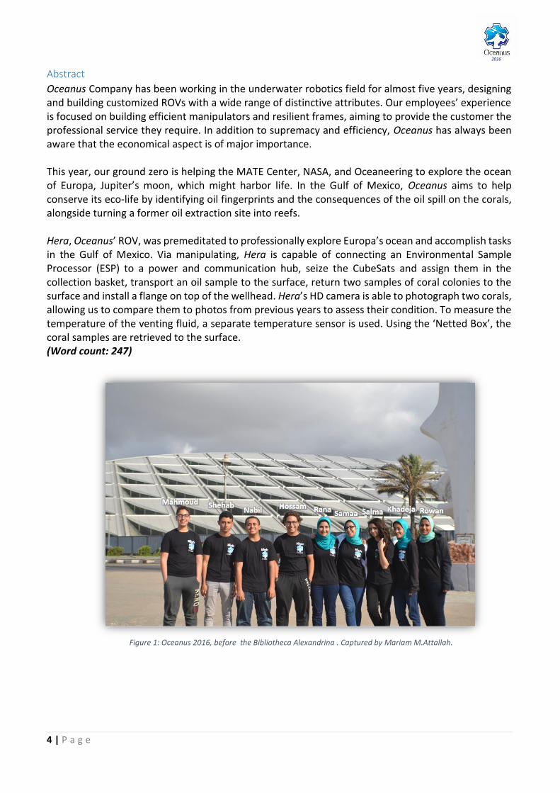
Figure 1: Oceanus 2016, before the Bibliotheca Alexandrina . Captured by Mariam M.Attallah.
5 | P a g e
2016
Mission Theme This year’s ROV competition has five tasks which are all unrelated but unite to have one goal which is linking experiments in outer space and applying them on Earth and the opposite. One task takes place in outer space, on Jupiter’s moon: Europa and the rest in the Gulf of Mexico.
Mission to Europa
Europa, one of the 63 discovered moons of Jupiter and among the four largest ones, fascinated the scientists for being the brightest in the solar system. This brightness is due to sunlight reflecting on its icy crust which may have, or had in the past, liquid water that can harbor life. Therefore, it is considered to be the prime focus of the scientists. [1] [2]
Mission-Critical Equipment Recovery
They are small satellites
that originally were part
of university projects
founded in 1999 and
launched in 2003 by
professors at American
universities. There
specifications are
explained in figure 3.
Their initial aim was
allowing undergraduates to design, construct
and experiment spacecrafts similar to the first
ever, Sputnik. Experimenting with CubeSats is
actually beneficial as techniques that work on
them can be applied on larger real-life
spacecrafts that accomplish more vital missions
in space. Today, almost anyone can build a
CubeSat as all they need in hard work and
around $50,000. CubeSats perform space
imaging, communications and atmospheric
research. [3] [4]
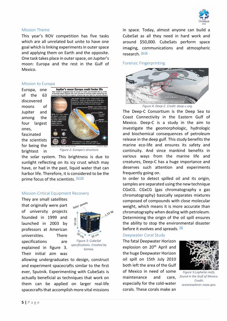
Forensic Fingerprinting
The Deep-C Consortium is the Deep Sea to Coast Connectivity in the Eastern Gulf of Mexico. Deep-C is a study in the aim to investigate the geomorphologic, hydrologic and biochemical consequences of petroleum release in the deep gulf. This study benefits the marine eco-life and ensures its safety and continuity. And since mankind benefits in various ways from the marine life and creatures, Deep-C has a huge importance and deserves such attention and experiments frequently going on. In order to detect spilled oil and its origin, samples are separated using the new technique CGxCG. CGxCG (gas chromatography x gas chromatography) basically separates mixtures composed of compounds with close molecular weight, which means it is more accurate than chromatography when dealing with petroleum. Determining the origin of the oil spill ensures the ability to stop the environmental disaster before it evolves and spreads. [5]
Deepwater Coral Study
The fatal Deepwater Horizon
explosion on 20th April and
the huge Deepwater Horizon
oil spill on 15th July 2010
both left the area of the Gulf
of Mexico in need of some
maintenance and care,
especially for the cold-water
corals. These corals make an
Figure 5:Lophelia reefs, found in the Gulf of Mexico.
Credit: oceanexplorer.noaa.gov.
Figure 2: Europa's structure.
Figure 3: CubeSat specifications. Created by
Samaa.
Figure 4: Deep-C. Credit: deep-c.org.
6 | P a g e
2016
important part of the marine eco-life in that
area, as they are used for food and shelter.
Scientists needed to take samples of the corals
and inspect the changes that occur to them
over time. [6]
Rigs-to-Reefs
The Bureau of Ocean Energy Management and the Bureau of Safety and Environmental Enforcement both developed the American program “Rigs-to-Reefs”. The aim of this program is turning anything from retired ships to oil platforms to be used for creating artificial reefs in order to support the marine life. In the ROV competition, it is our mission to convert a former wellhead into a reef by securing it and adding bolts on its top. Wellheads are the ideal artificial reefs as they are durable; they are made from strong material and have been in the seawater for long with no corrosion.
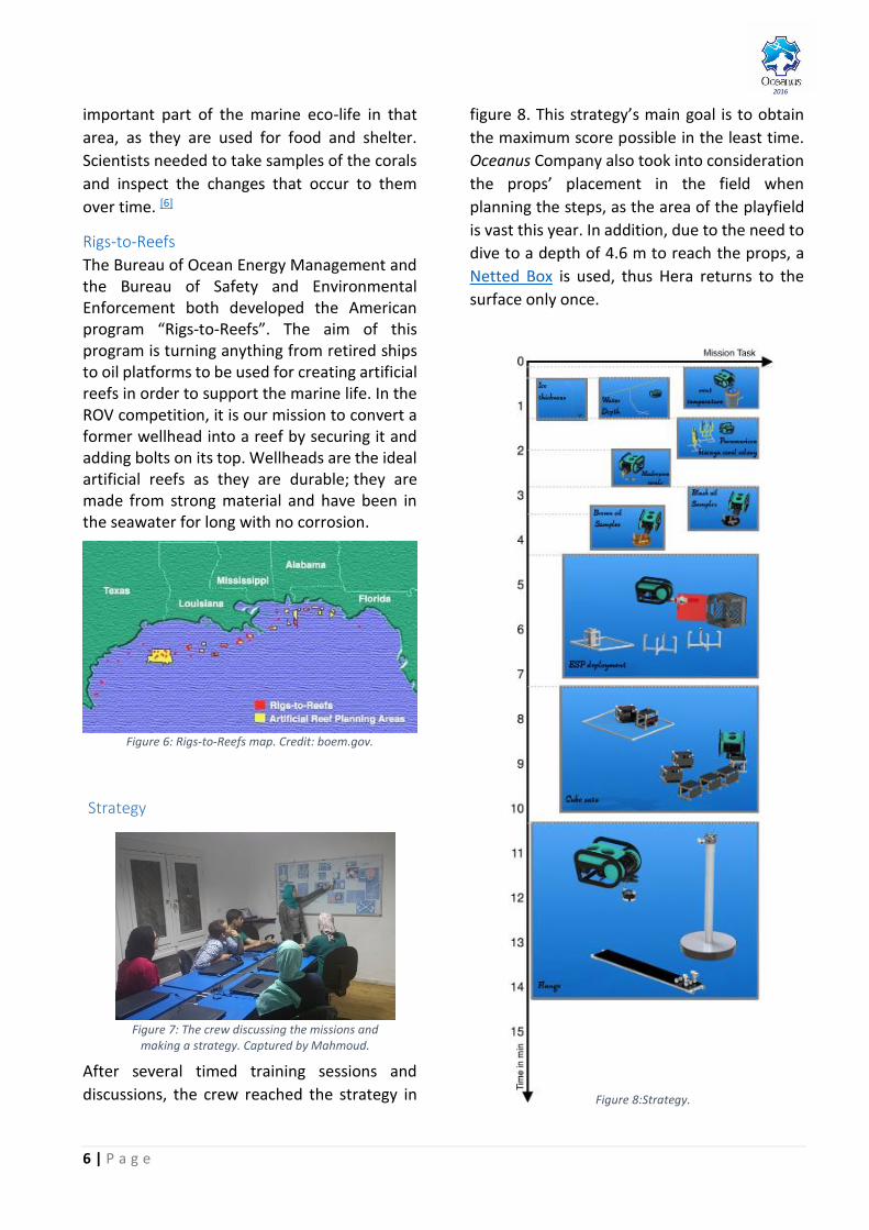
Strategy
After several timed training sessions and
discussions, the crew reached the strategy in
figure 8. This strategy’s main goal is to obtain
the maximum score possible in the least time.
Oceanus Company also took into consideration
the props’ placement in the field when
planning the steps, as the area of the playfield
is vast this year. In addition, due to the need to
dive to a depth of 4.6 m to reach the props, a
Netted Box is used, thus Hera returns to the
surface only once.
Figure 6: Rigs-to-Reefs map. Credit: boem.gov.
Figure 7: The crew discussing the missions and making a strategy. Captured by Mahmoud.
Figure 8:Strategy.

7 | P a g e
2016
1. Design Rational and Vehicle System
The mechanical team’s aim is designing an efficient ROV to accomplish the missions while withstanding unexpected and extreme conditions. Hera meets the specific parameters required by the customers such as having a diameter less than 48 centimeters and weighing less than 11 kg. The vehicle’s design includes a choice of thrusters and a configuration to perform in different degrees of freedom. Also, it includes the placement of the electrical canister, cameras, payloads, manipulator and sensors. Without a doubt, every detail placed had to be studied from numerous perspectives to create a stable efficient vehicle. This study includes calculating its weight and buoyancy for further uses as explained in details in the following sections.
Figure 9: Hera, Oceanus' 2016 ROV. Captured by Samaa.
1.1. Frame
Hera’s frame is made from laser-cut PEX which is a chemically cross-linked polyethylene. There are many holes in the frame, they allow the customer to easily change the configuration of the thrusters and add payloads. PEX has outstanding mechanical and physical properties such as
no water absorption. thermal and chemical insulation. shock absorption.
Amongst its other beneficial properties are its durability and stability as Oceanus’ aim is to
build durable configurable ROVs to perform many variant missions and not only one type of tasks. Hera has a simple compact design consisting of three PEX sheets: two identical side
sheets: act as bumpers and aid in absorbing minor impacts.
one main sheet: (shown
in figure 11) houses all the components; encloses a total of six thrusters (four laterally and two vertically), the electrical canister and the float. Both vertical thrusters are mounted on this sheet using 3D- printed brackets shown in figure 12. In addition, the lateral thrusters are secured directly using four screws.
1.2. Thrusters
Throughout the years, the crew gained huge experience as they tested and compared many components, the thrusters for instance. Thus, they were able to choose the optimal thruster type this year. T100 brushless motor is light, compact and has a small control. Its thrust is relatively high, taking the cost into consideration.
Figure 11: SolidWorks design of the main sheet. Designed by
Rana.
Figure 10: SolidWorks design of the side sheet.
Designed by Rana.
Figure 13: T-100 thrusters used this
year.
Figure 12: Laser-cut
side sheet.

8 | P a g e
2016
Hera has six T100 electric brushless motors. The top thrusters are fixed using 3D-printed brackets as shown in figure 14. The rest of the thrusters are directly mounted on the main sheet.
These motors were chosen for their high
power-to-thrust ratio and their cost-
effectiveness compared to similarly priced
motors. They are also controlled via an
Electronic Speed Controller (ESC). These
features provided an easy and stable
maneuvering which is required in performing
mission tasks. A proof of this built-up years of
trials is the table in the appendix where it
provides the comparison of all the thrusters
Oceanus team has tested and used before. The
six motors’ configuration can be seen in the
SolidWorks’ design in figure 15.
1.3. Degrees of Freedom
Hera’s design has six thrusters which provide
five degrees of freedom (shown in figure 16):
three translations: surge, heave and sway,
along the longitudinal, vertical, and
transverse (lateral) axes, respectively.
two rotations: yaw and pitch about these
same respective axes.
Each degree of freedom is needed for a different purpose:
Heave:
o Task #1: insert the temperature
sensor into the venting fluid.
o Task #2: place the CubeSats in the
basket.
o Task #3: collect oil mat from the
bottom.
o Task #5: install a flange.
Surge:
o Task#1: Connect ESP.
The rest of the degrees of freedom ease the
piloting of Hera.
1.4. Buoyancy
Buoyancy was a crucial factor in Hera’s
designing process. The mechanical team of
Oceanus Company thought that it was better to
design the vehicle for the most favorable
buoyancy first rather than building the vehicle
and then adjusting the buoyancy by adding
weights or floats.
Horizontal thrusters
Lateral thrusters
Vertical thrusters
Figure 15: The configuration of the motors of Hera. Created by Samaa.
Figure 16: Degree of Freedom of Hera. Created by Samaa.
A bracket
Figure 14: SolidWorks of thrusters fixed to the sheet with the 3D-printed brackets, by Rana.
9 | P a g e
2016
Buoyancy is defined as the upward force
exerted by the fluid on a body that is immersed
in it and according to Archimedes’ principle;
the magnitude of this force -buoyant force- is
equal to the magnitude of the weight of fluid
displaced by this body, in our case Hera as
shown in figure 17.
Hera will float, sink or remain critically floating
depending on the net force of both the weight
and the buoyant force generated by the ROV
body, this net force may result in one of these
three conditions:
Positive: buoyant force > weight: the ROV
floats.
Neutral: buoyant force = weight: the ROV
neither floats nor sinks.
Negative: buoyant force < weight: the ROV
sinks.
An ROV is preferred to be slightly positive
buoyant, in other words critically floating, as
this allows it to gradually move upward when
no thrust is applied. An advantage of Hera
having a slightly positive buoyant is that it saves
power and time to return to the surface.
While carrying out missions, the ROV needs to
be stable and almost stationary; therefore,
buoyancy is adjusted to ease the pilot’s task as
he will not need to operate the thrusters as the
ROV returns on its own. Also, this buoyancy
also prevents obscure video footage from the
onboard cameras.
Another important consideration is the
position each force is acting through; a favored
state is hydrostatic equilibrium which is when
the weight and buoyant forces are equal and
collinear. In our case, the buoyant force is
slightly larger than the weight but it must be
collinear.
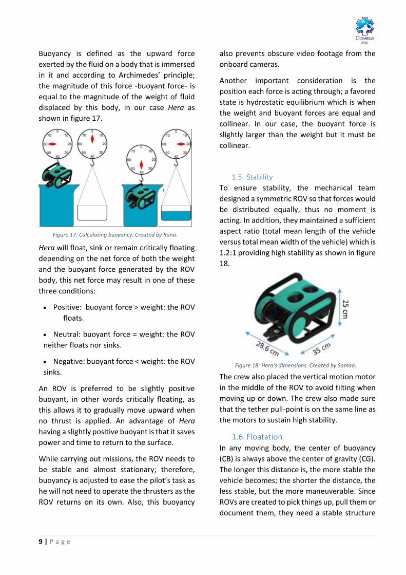
1.5. Stability
To ensure stability, the mechanical team
designed a symmetric ROV so that forces would
be distributed equally, thus no moment is
acting. In addition, they maintained a sufficient
aspect ratio (total mean length of the vehicle
versus total mean width of the vehicle) which is
1.2:1 providing high stability as shown in figure
18.
The crew also placed the vertical motion motor
in the middle of the ROV to avoid tilting when
moving up or down. The crew also made sure
that the tether pull-point is on the same line as
the motors to sustain high stability.
1.6. Floatation In any moving body, the center of buoyancy
(CB) is always above the center of gravity (CG).
The longer this distance is, the more stable the
vehicle becomes; the shorter the distance, the
less stable, but the more maneuverable. Since
ROVs are created to pick things up, pull them or
document them, they need a stable structure
Figure 18: Hera's dimensions. Created by Samaa.
Figure 17: Calculating buoyancy. Created by Rana.
10 | P a g e
2016
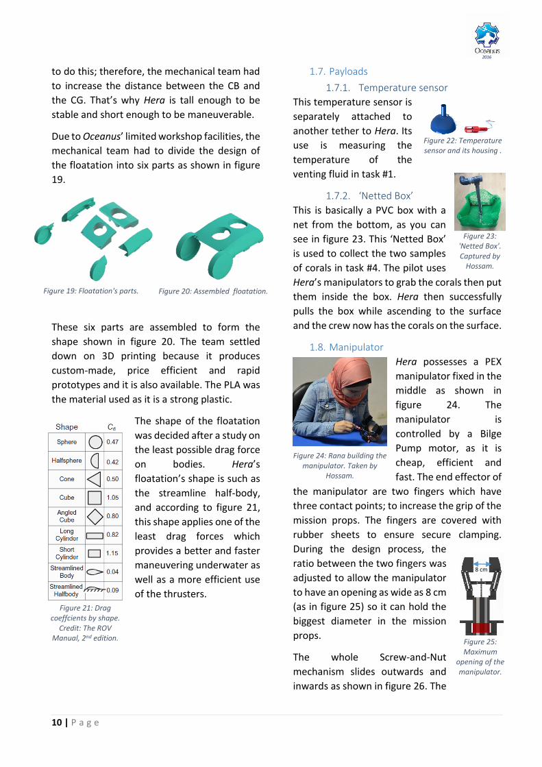
to do this; therefore, the mechanical team had
to increase the distance between the CB and
the CG. That’s why Hera is tall enough to be
stable and short enough to be maneuverable.
Due to Oceanus’ limited workshop facilities, the
mechanical team had to divide the design of
the floatation into six parts as shown in figure
19.
These six parts are assembled to form the
shape shown in figure 20. The team settled
down on 3D printing because it produces
custom-made, price efficient and rapid
prototypes and it is also available. The PLA was
the material used as it is a strong plastic.
The shape of the floatation
was decided after a study on
the least possible drag force
on bodies. Hera’s
floatation’s shape is such as
the streamline half-body,
and according to figure 21,
this shape applies one of the
least drag forces which
provides a better and faster
maneuvering underwater as
well as a more efficient use
of the thrusters.
1.7. Payloads
1.7.1. Temperature sensor
This temperature sensor is
separately attached to
another tether to Hera. Its
use is measuring the
temperature of the
venting fluid in task #1.
1.7.2. ‘Netted Box’
This is basically a PVC box with a
net from the bottom, as you can
see in figure 23. This ‘Netted Box’
is used to collect the two samples
of corals in task #4. The pilot uses
Hera’s manipulators to grab the corals then put
them inside the box. Hera then successfully
pulls the box while ascending to the surface
and the crew now has the corals on the surface.
1.8. Manipulator
Hera possesses a PEX
manipulator fixed in the
middle as shown in
figure 24. The
manipulator is
controlled by a Bilge
Pump motor, as it is
cheap, efficient and
fast. The end effector of
the manipulator are two fingers which have
three contact points; to increase the grip of the
mission props. The fingers are covered with
rubber sheets to ensure secure clamping.
During the design process, the
ratio between the two fingers was
adjusted to allow the manipulator
to have an opening as wide as 8 cm
(as in figure 25) so it can hold the
biggest diameter in the mission
props.
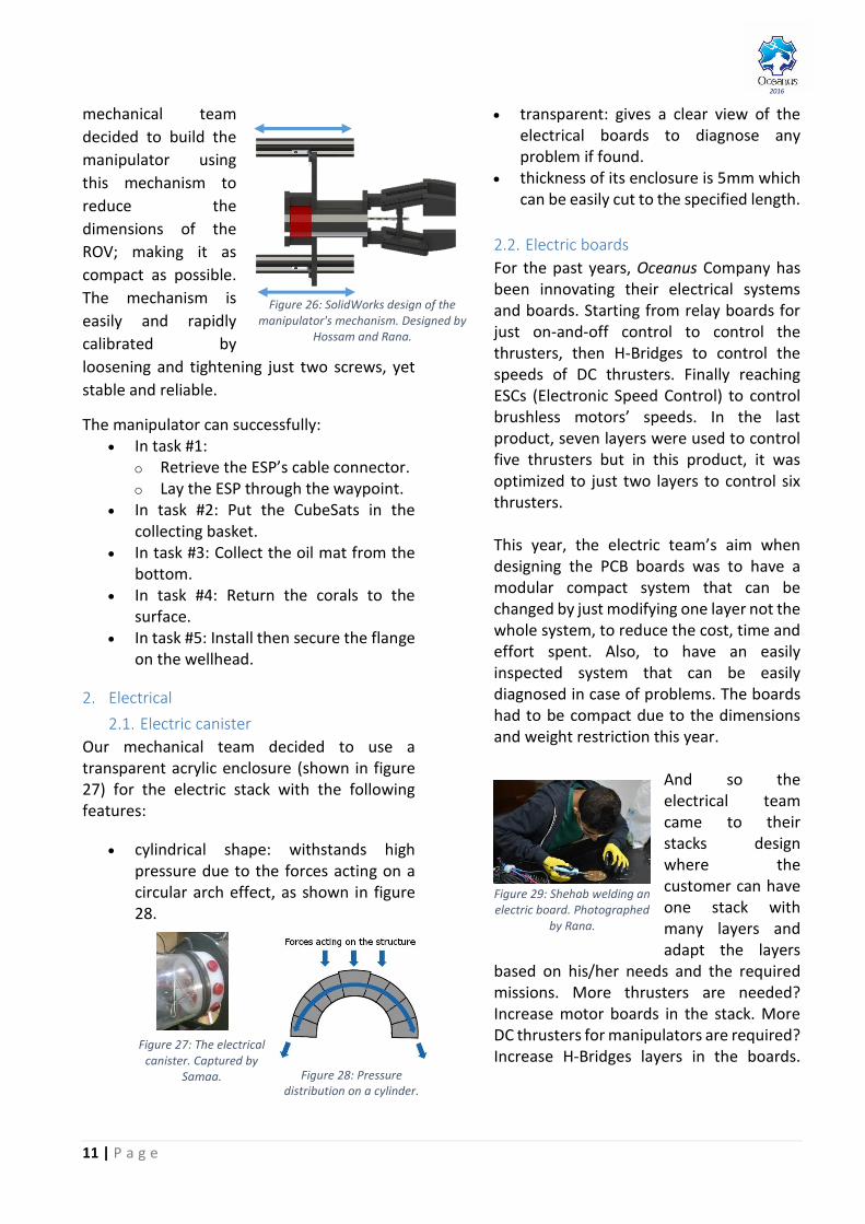
The whole Screw-and-Nut
mechanism slides outwards and
inwards as shown in figure 26. The
Figure 23: 'Netted Box'. Captured by
Hossam.
Figure 19: Floatation's parts. Figure 20: Assembled floatation.
Figure 21: Drag coeffcients by shape.
Credit: The ROV Manual, 2nd edition.
8 cm
Figure 25: Maximum
opening of the manipulator.
Figure 22: Temperature sensor and its housing .
Figure 24: Rana building the manipulator. Taken by
Hossam.
11 | P a g e
2016
mechanical team
decided to build the
manipulator using
this mechanism to
reduce the
dimensions of the
ROV; making it as
compact as possible.
The mechanism is
easily and rapidly
calibrated by
loosening and tightening just two screws, yet
stable and reliable.
The manipulator can successfully: In task #1:
o Retrieve the ESP’s cable connector. o Lay the ESP through the waypoint.
In task #2: Put the CubeSats in the collecting basket.
In task #3: Collect the oil mat from the bottom.
In task #4: Return the corals to the surface.
In task #5: Install then secure the flange on the wellhead.
2. Electrical
2.1. Electric canister
Our mechanical team decided to use a transparent acrylic enclosure (shown in figure 27) for the electric stack with the following features:
cylindrical shape: withstands high pressure due to the forces acting on a circular arch effect, as shown in figure 28.
transparent: gives a clear view of the electrical boards to diagnose any problem if found.
thickness of its enclosure is 5mm which can be easily cut to the specified length.
2.2. Electric boards
For the past years, Oceanus Company has been innovating their electrical systems and boards. Starting from relay boards for just on-and-off control to control the thrusters, then H-Bridges to control the speeds of DC thrusters. Finally reaching ESCs (Electronic Speed Control) to control brushless motors’ speeds. In the last product, seven layers were used to control five thrusters but in this product, it was optimized to just two layers to control six thrusters. This year, the electric team’s aim when designing the PCB boards was to have a modular compact system that can be changed by just modifying one layer not the whole system, to reduce the cost, time and effort spent. Also, to have an easily inspected system that can be easily diagnosed in case of problems. The boards had to be compact due to the dimensions and weight restriction this year.
And so the electrical team came to their stacks design where the customer can have one stack with many layers and adapt the layers
based on his/her needs and the required missions. More thrusters are needed? Increase motor boards in the stack. More DC thrusters for manipulators are required? Increase H-Bridges layers in the boards.
Figure 27: The electrical canister. Captured by
Samaa. Figure 28: Pressure distribution on a cylinder.
Figure 26: SolidWorks design of the manipulator's mechanism. Designed by
Hossam and Rana.
Figure 29: Shehab welding an electric board. Photographed
by Rana.

12 | P a g e
2016
The two layers are connected using copper spacers which allow the crew avoid tanglement of cables and to trace the connections easier: 1. The motor control board: has four ESCs, four current sensors and two relays for an on-and-off control for instance flashlights. 2. The main control and sensors board: has a Pololu 18-Channel Maestro which controls the six thrusters, the DC motors for the manipulator using a Pololu VNH5019 Motor Driver and takes the reading from the sensor and sends them to the main station serially.
2.3. Sensors
2.3.1. Pressure sensor:
A Blue Robotics pressure
sensor which is shown in
figure 31 is used to
measure the water
depth necessary for task
#1. The sensor can measure water pressure up
to 30 bar, which rounds to the depth of 300m,
with depth resolution of 2mm. With a
maximum error allowed of 10cm, this
resolution will enhance the efficiency in
measuring the depth. Using an interface, the
pressure reading is converted into a value of
depth.
2.3.2. Temperature sensor:
A Blue Robotics LM35
temperature sensor shown
in figure 32, capable of
measuring temperatures
from -40°C to 125°C, is used
for task #1 to determine the
temperature of the venting fluid. This sensor is
connected separately to tether using four
wires: 5V, ground and I²C.
2.3.3. Water detection sensor:
This Pololu sensor, shown in figure 33, is fixed next to the end caps of the electric canister. It is essential as it detects water leakage in the electric canister
for safety reasons and notifies the pilot.
2.3.4. Current sensor:
Pololu current sensor is used for overcurrent detection. In Hera’s design, every motor has a current sensor connected in series with it to ensure the maximum safety of the ROV and to monitor the behavior of the motors. The current sensors’ reading are displayed on the main driving station.
2.4. Controller
Oceanus’ pilot
concluded using
Thrustmaster T-Flight
Hotas X Flight Stick
(shown in figure 34) as
it is easy to use and
allows Hera all the
degrees of freedom it needs to accomplish the
missions. Also, it has 12 programmable buttons
and five axles, allowing the pilot to control all
at once. The controller is connected to the
laptop as well as all different components of
the tether. The stick’s configuration is
illustrated in the appendix.
2.5. Camera
Hera is mounted with three cameras: a front camera in the electronic can, a rear camera and a camera fixed on the manipulators.
Figure 34: Thrustmaster T-Flight Hotas X Flight
Stick controller.
Figure 31:Pressure sensor.
Figure 32: Temperature
sensor.
Figure 33: Water detection sensor.
Figure 35: Main camera.
Figure 30: Main board. Captured by
Rana.
13 | P a g e
2016
The front IP camera (shown in figure 35) gives the pilot a wide view of playfield underwater the camera is mounted on a servo to tilt it up and down 180º, shown in figure 36. The rear camera (shown in figure 37) helps the pilot avoid hitting coral reefs. Also, it helps him ensure the ESP cable through the waypoints. The camera fixed on the manipulator allows the
pilot to observe what Hera grabs or pulls, which is really useful when collecting the coral samples in task #4, retrieving the CubeSats in task #2 or putting the flange on top of the wellhead and the wellhead cap on top of the flange in task #5.
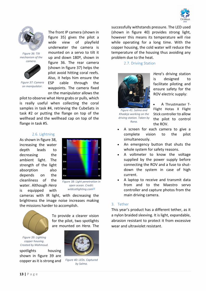
2.6. Lightning
As shown in figure 38, increasing the water depth leads to decreasing the ambient light. The strength of the light absorption also depends on the cleanliness of the water. Although Hera is equipped with cameras with IR light, with decreasing the brightness the image noise increases making the missions harder to accomplish.
To provide a clearer vision for the pilot, two spotlights are mounted on Hera. The
spotlights housing shown in figure 39 are copper as it is strong and
successfully withstands pressure. The LED used (shown in figure 40) provides strong light, however this means its temperature will rise while operating for a long time. With the copper housing, the cold water will reduce the temperature of the housing thus avoiding any problem due to the heat.
2.7. Driving Station
Hera’s driving station is designed to facilitate piloting and ensure safety for the ROV electric supply: A Thrustmaster T-Flight Hotas X Flight
Stick controller to allow the pilot to control the ROV.
A screen for each camera to give a complete vision to the pilot simultaneously.
An emergency button that shuts the whole system for safety reasons.
A voltmeter to know the voltage supplied by the power supply before connecting the ROV and a fuse to shut-down the system in case of high current.
A laptop to receive and transmit data from and to the Maestro servo controller and capture photos from the main driving camera.
3. Tether
This year’s product has a different tether, as it
a nylon braided sleeving. It is light, expandable,
abrasion resistant to protect it from excessive
wear and ultraviolet resistant.
Figure 38: Light penetration in open ocean. Credit:
wildcatlighting.com[7]
Figure 40: LEDs. Captured by Salma.
Figure 39: Lighting copper housing.
Created by Mahmoud.
Figure 36: Tilt mechanism of the
camera.
Figure 37: Camera on manipulator.
Figure 41: Salma and Khadeja working on the driving station. Taken by
Rana.

14 | P a g e
2016
The tether is 20 m long, since
it needs to dive 4.6 m to
reach the playfield and 8 m
to navigate through the
props, also considering that
the station is 5 m away from
the playfield. The tether
weighs 3.4 kg and has a
diameter of 2.5 cm. The
relations between the tether
drag, the speed, and the
diameter are illustrated in
the graphs (figure 42).
The coefficient of drag of
cables ranges from 1.2 for
apart cables; 0.5-0.6 for hair-
faired cable; and 0.1-0.2 for
faired cables which depends
on the diameter of the cable.
Since the cylindrical form has
the highest coefficient of
drag, the crew used cable
fairings to aid in drag reduction can have a
significant impact. Therefore, Oceanus
managed to reduce the coefficient of drag of
the tether by the diameter reduction.
The tether lines are distributed as shown in the
SID. The other side of the tether is terminated
inside the electronics can with a 12-pin water-
sealed connector. This connector is easily
plugged in and out allowing a customizable
tether.
4. Software The software consists of
the surface Graphical
User Interface (GUI) C#
code.
The GUI gives the pilot
the exact heading of the
ROV and the depth
reached via the compass and pressure sensor. By
using an error correcting algorithm, the ROV can
remain stationary during missions that need high
precision.
The current sensors connected on each thruster
enable Hera to utilize the maximum speed for
maneuvering, below the current limit: 25 A.
4. Isolation System
The isolation techniques were improved this year, as the mechanical crew tested newer methods to produce a safer and more reliable ROV. Thus, all circuit boards are put inside an acrylic canister which is sealed with end caps (figure 45) with 2 O-rings around, to prevent any water leakage to the boards.
The cable penetrators are new things this year. They proved to be more efficient and easier to use. Despite their high price after shipping and tariff. They have O-rings as well, as you can see in figure 46.
With a vacuum hand pump, air is removed from the canister and a gauge is monitored for leaks. This test is conducted prior to every operation of the vehicle.
5. Safety
5.1. Safety Philosophy
Safety has always been on top of Oceanus’ priorities for both staff and ROV. The company’s safety philosophy can be resumed in “Safe working and efficient learning”. Mentors have trained members to deal with tools and machinery safely. Also, strict rules and guidelines have been enforced when handling the components and the ROV itself as there is a safety checklist placed in the lab.
Figure 45: End caps. Captured by Samaa.
Figure 46: O-rings in the cable penetrators. Captured by Samaa.
Figure 44: Ahmed coding. Captured by Samaa.
4.6
m
8 m
Figure 43: Tether length calculation. Created by Rana.
Figure 42: Tether drag, speed and
diameter relations graph. Credit: The ROV Manual, 2nd
edition.
15 | P a g e
2016
5.2. Safety checklist
In order to keep the crew safe in the workshop, the safety officer, Rowan‘s job has been to maintain the workshops safe by checking daily the functionality of the equipment, the presence of caution sign on moving parts and more, you may refer to appendix to read the whole safety checklist.
5.3. Workshop
Providing a safe and well-organized workspace ensures physical safety and maximizes productivity as well. The crew always makes sure that there are no trailing cables that would cause anyone to trip and none of the tools or are placed on the ground; at all times our components and tools are placed orderly in the storage area. In addition, if any tools were worn out or damaged -such as cutting blades or drilling bits or cutters- they are immediately replaced with newer and safer models. Needless to say food and drinks are not allowed inside the workshop.
5.4. Crew Safety
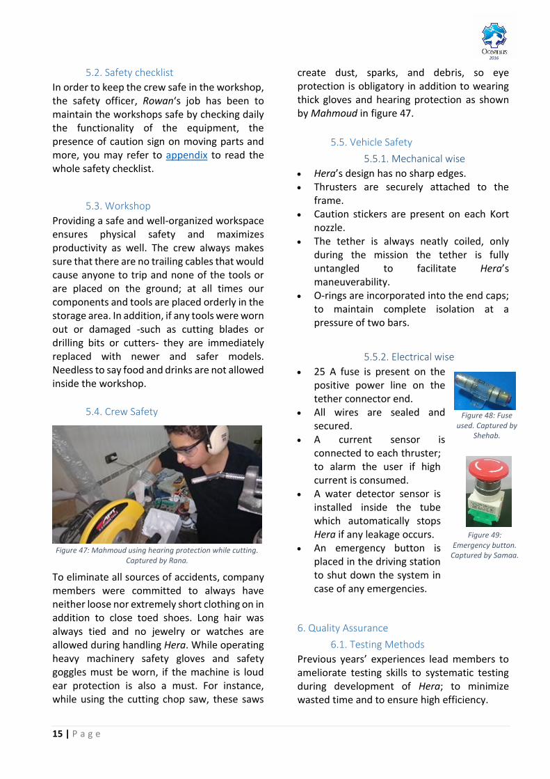
To eliminate all sources of accidents, company members were committed to always have neither loose nor extremely short clothing on in addition to close toed shoes. Long hair was always tied and no jewelry or watches are allowed during handling Hera. While operating heavy machinery safety gloves and safety goggles must be worn, if the machine is loud ear protection is also a must. For instance, while using the cutting chop saw, these saws
create dust, sparks, and debris, so eye protection is obligatory in addition to wearing thick gloves and hearing protection as shown by Mahmoud in figure 47.
5.5. Vehicle Safety
5.5.1. Mechanical wise
Hera’s design has no sharp edges. Thrusters are securely attached to the
frame. Caution stickers are present on each Kort
nozzle. The tether is always neatly coiled, only
during the mission the tether is fully untangled to facilitate Hera’s maneuverability.
O-rings are incorporated into the end caps; to maintain complete isolation at a pressure of two bars.
5.5.2. Electrical wise
25 A fuse is present on the positive power line on the tether connector end.
All wires are sealed and secured.
A current sensor is connected to each thruster; to alarm the user if high current is consumed.
A water detector sensor is installed inside the tube which automatically stops Hera if any leakage occurs.
An emergency button is placed in the driving station to shut down the system in case of any emergencies.
6. Quality Assurance
6.1. Testing Methods
Previous years’ experiences lead members to ameliorate testing skills to systematic testing during development of Hera; to minimize wasted time and to ensure high efficiency.
Figure 49: Emergency button.
Captured by Samaa.
Figure 48: Fuse used. Captured by
Shehab.
Figure 47: Mahmoud using hearing protection while cutting. Captured by Rana.
16 | P a g e
2016
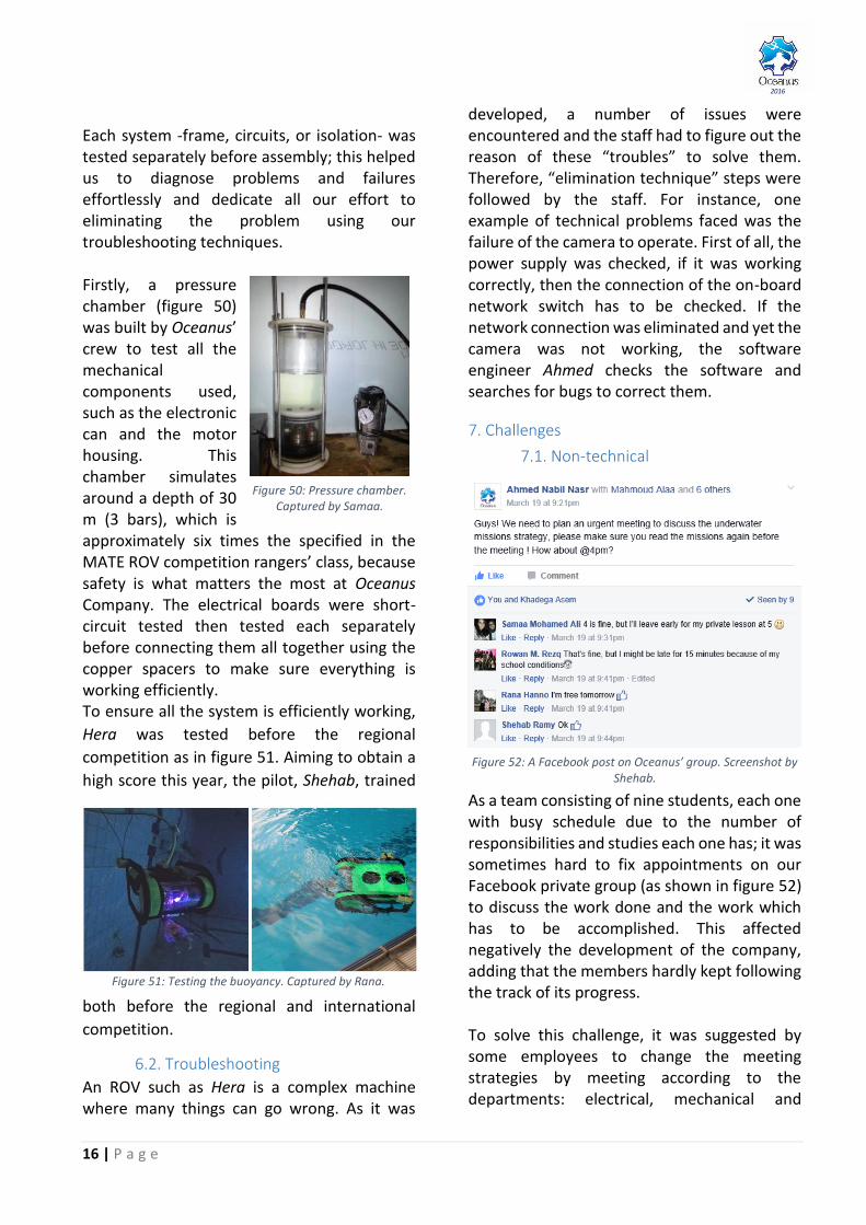
Each system -frame, circuits, or isolation- was tested separately before assembly; this helped us to diagnose problems and failures effortlessly and dedicate all our effort to eliminating the problem using our troubleshooting techniques. Firstly, a pressure chamber (figure 50) was built by Oceanus’ crew to test all the mechanical components used, such as the electronic can and the motor housing. This chamber simulates around a depth of 30 m (3 bars), which is approximately six times the specified in the MATE ROV competition rangers’ class, because safety is what matters the most at Oceanus Company. The electrical boards were short-circuit tested then tested each separately before connecting them all together using the copper spacers to make sure everything is working efficiently. To ensure all the system is efficiently working,
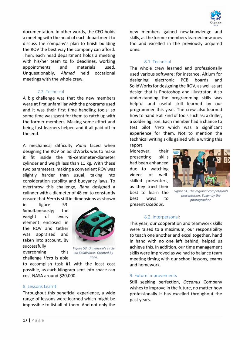
Hera was tested before the regional
competition as in figure 51. Aiming to obtain a
high score this year, the pilot, Shehab, trained
both before the regional and international
competition.
6.2. Troubleshooting
An ROV such as Hera is a complex machine where many things can go wrong. As it was
developed, a number of issues were encountered and the staff had to figure out the reason of these “troubles” to solve them. Therefore, “elimination technique” steps were followed by the staff. For instance, one example of technical problems faced was the failure of the camera to operate. First of all, the power supply was checked, if it was working correctly, then the connection of the on-board network switch has to be checked. If the network connection was eliminated and yet the camera was not working, the software engineer Ahmed checks the software and searches for bugs to correct them.
7. Challenges
7.1. Non-technical
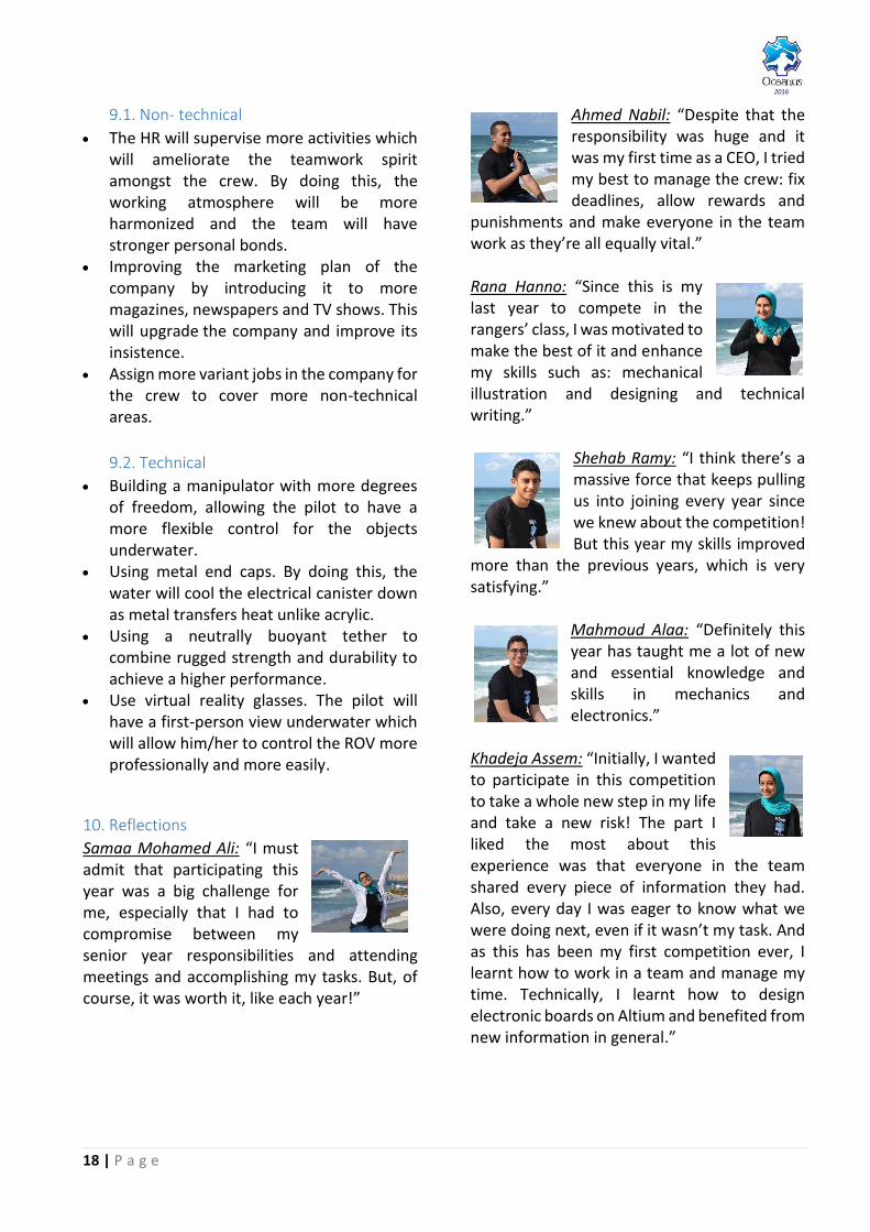
As a team consisting of nine students, each one with busy schedule due to the number of responsibilities and studies each one has; it was sometimes hard to fix appointments on our Facebook private group (as shown in figure 52) to discuss the work done and the work which has to be accomplished. This affected negatively the development of the company, adding that the members hardly kept following the track of its progress. To solve this challenge, it was suggested by some employees to change the meeting strategies by meeting according to the departments: electrical, mechanical and
Figure 52: A Facebook post on Oceanus’ group. Screenshot by Shehab.
Figure 50: Pressure chamber. Captured by Samaa.
Figure 51: Testing the buoyancy. Captured by Rana.
17 | P a g e
2016
documentation. In other words, the CEO holds a meeting with the head of each department to discuss the company’s plan to finish building the ROV the best way the company can afford. Then, each head department holds a meeting with his/her team to fix deadlines, working appointments and materials used. Unquestionably, Ahmed held occasional meetings with the whole crew.
7.2. Technical
A big challenge was that the new members were at first unfamiliar with the programs used and it was their first time handling tools; so some time was spent for them to catch up with the former members. Making some effort and being fast learners helped and it all paid off in the end. A mechanical difficulty Rana faced when designing the ROV on SolidWorks was to make it fit inside the 48-centimeter-diameter cylinder and weigh less than 11 kg. With these two parameters, making a convenient ROV was slightly harder than usual, taking into consideration stability and buoyancy laws. To overthrow this challenge, Rana designed a cylinder with a diameter of 48 cm to constantly ensure that Hera is still in dimensions as shown in figure 53. Simultaneously; the weight of every element enclosed in the ROV and tether was appraised and taken into account. By successfully overcoming this challenge Hera is able to accomplish task #1 with the least cost possible, as each kilogram sent into space can cost NASA around $20,000.
8. Lessons Learnt
Throughout this beneficial experience, a wide range of lessons were learned which might be impossible to list all of them. And not only the
new members gained new knowledge and skills, as the former members learned new ones too and excelled in the previously acquired ones.
8.1. Technical
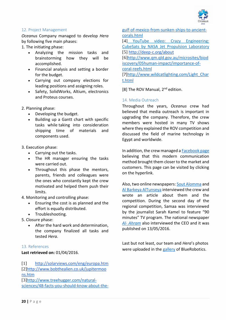
The whole crew learned and professionally used various software; for instance, Altium for designing electronic PCB boards and SolidWorks for designing the ROV, as well as art design that is Photoshop and Illustrator. Also understanding the programming skills was helpful and useful skill learned by our programmer this year. The crew also learned how to handle all kind of tools such as: a driller, a soldering iron. Each member had a chance to test pilot Hera which was a significant experience for them. Not to mention the technical writing skills gained while writing this report. Moreover, their presenting skills had been enhanced due to watching videos of well-skilled presenters, as they tried their best to learn the best ways to present Oceanus.
8.2. Interpersonal:
This year, our cooperation and teamwork skills were raised to a maximum, our responsibility to teach one another and excel together, hand in hand with no one left behind, helped us achieve this. In addition, our time management skills were improved as we had to balance team meeting timing with our school lessons, exams and homework.
9. Future Improvements
Still seeking perfection, Oceanus Company wishes to improve in the future, no matter how professionally it has excelled throughout the past years.
Figure 53: Dimension's circle on SolidWorks. Created by
Rana.
Figure 54: The regional competition's presentation. Taken by the
photographer.
18 | P a g e
2016
9.1. Non- technical
The HR will supervise more activities which will ameliorate the teamwork spirit amongst the crew. By doing this, the working atmosphere will be more harmonized and the team will have stronger personal bonds.
Improving the marketing plan of the company by introducing it to more magazines, newspapers and TV shows. This will upgrade the company and improve its insistence.
Assign more variant jobs in the company for the crew to cover more non-technical areas.
9.2. Technical
Building a manipulator with more degrees of freedom, allowing the pilot to have a more flexible control for the objects underwater.
Using metal end caps. By doing this, the water will cool the electrical canister down as metal transfers heat unlike acrylic.
Using a neutrally buoyant tether to combine rugged strength and durability to achieve a higher performance.
Use virtual reality glasses. The pilot will have a first-person view underwater which will allow him/her to control the ROV more professionally and more easily.
10. Reflections
Samaa Mohamed Ali: “I must admit that participating this year was a big challenge for me, especially that I had to compromise between my senior year responsibilities and attending meetings and accomplishing my tasks. But, of course, it was worth it, like each year!”
Ahmed Nabil: “Despite that the responsibility was huge and it was my first time as a CEO, I tried my best to manage the crew: fix deadlines, allow rewards and
punishments and make everyone in the team work as they’re all equally vital.” Rana Hanno: “Since this is my last year to compete in the rangers’ class, I was motivated to make the best of it and enhance my skills such as: mechanical illustration and designing and technical writing.”
Shehab Ramy: “I think there’s a massive force that keeps pulling us into joining every year since we knew about the competition! But this year my skills improved
more than the previous years, which is very satisfying.”
Mahmoud Alaa: “Definitely this year has taught me a lot of new and essential knowledge and skills in mechanics and electronics.”
Khadeja Assem: “Initially, I wanted to participate in this competition to take a whole new step in my life and take a new risk! The part I liked the most about this experience was that everyone in the team shared every piece of information they had. Also, every day I was eager to know what we were doing next, even if it wasn’t my task. And as this has been my first competition ever, I learnt how to work in a team and manage my time. Technically, I learnt how to design electronic boards on Altium and benefited from new information in general.”

19 | P a g e
2016
Rowan Rezq: “I really enjoyed my first ROV competition as I got to work in a big team and learn new interesting engineering topics.”
Salma Mohamed Ali: “Participating in the ROV competition taught me an important everyday life skill: time management! Also, it offered me the opportunity to learn software, electrical and mechanical engineering which helped me in deciding my
future career: studying computer science later in college.”
Hossam Hanno: “This year my goal was not only learn but also compete internationally.”
11. Teamwork
An exceptional ROV cannot be accomplished with the lack of teamwork, as teamwork is considered a main factor in any company’s success. After dividing the staff into mechanical, electrical, software and documentation teams, former employees were chosen for leading positions: Ahmed became the CEO, Rana became the head of mechanical team and CFO and Shehab became the head of electrical team. By doing this, Oceanus ensured that each team member has a responsibility to contribute equally and offer their unique perspective on a problem to arrive to the best possible outcome. Afterwards, Hera was manufactured from scratch, by Oceanus staff, though mentors’ advice and critique were still welcomed. In addition, each electrical and mechanical team
member took part in writing brief Google Documents on the construction of the ROV; as these documents facilitated enormously writing the main technical report required by the MATE ROV competition which was Samaa and Rana’s task, the R&D and documentation officers. In other words, both of the writing of this technical report and the construction of the ROV were completely a company effort. A detailed Gantt chart developed was developed by the CEO with the help of the HR manager and the chiefs of departments, in order to ensure that all the work will be done in time. He took so much care to make all the members meet the deadlines, to ensure that the team was progressing and the work was being done as it was supposed to. The table is also provided in the appendix. The company members were always in touch.
They were communicating through phone calls and social media to synchronize weekly and occasionally meeting times and discuss their tasks together. These communications built a wonderful spirit of strong teamwork in the company which strengthened the cooperation between the staff members. As a result, the rate of work was enhanced too.
Figure 57: A meeting, few days before the regional competition.
Captured by Eng. Kareem.
Figure 55: Samaa and Rana working on the technical report.
Captured by Salma.
Figure 56: Samaa, the HR manager, video-calling Rowan on Hangouts to update her because she was out of town.
Screenshot taken by Samaa.
20 | P a g e
2016
12. Project Management
Oceanus Company managed to develop Hera by following five main phases: 1. The initiating phase:
Analyzing the mission tasks and brainstorming how they will be accomplished.
Financial analysis and setting a border for the budget.
Carrying out company elections for leading positions and assigning roles.
Safety, SolidWorks, Altium, electronics and Proteus courses.
2. Planning phase:
Developing the budget. Building up a Gantt chart with specific
tasks while taking into consideration shipping time of materials and components used.
3. Execution phase:
Carrying out the tasks. The HR manager ensuring the tasks
were carried out. Throughout this phase the mentors,
parents, friends and colleagues were the ones who constantly kept the crew motivated and helped them push their limits.
4. Monitoring and controlling phase: Ensuring the cost is as planned and the
effort is equally distributed. Troubleshooting.
5. Closure phase: After the hard work and determination,
the company finalized all tasks and tested Hera.
13. References
Last retrieved on: 01/04/2016.
[1] http://solarviews.com/eng/europa.htm [2]http://www.bobthealien.co.uk/jupitermoons.htm [3]http://www.treehugger.com/natural-sciences/48-facts-you-should-know-about-the-
gulf-of-mexico-from-sunken-ships-to-ancient-corals.html [4] YouTube video: Crazy Engineering: CubeSats by NASA Jet Propulsion Laboratory [5] http://deep-c.org/about [6]http://www.qm.qld.gov.au/microsites/biodiscovery/05human-impact/importance-of-coral-reefs.html [7]http://www.wildcatlighting.com/Light_Char
t.html
[8] The ROV Manual, 2nd edition.
14. Media Outreach
Throughout the years, Oceanus crew had believed that media outreach is important in upgrading the company. Therefore, the crew members were hosted in many TV shows where they explained the ROV competition and discussed the field of marine technology in Egypt and worldwide. In addition, the crew managed a Facebook page believing that this modern communication method brought them closer to the market and customers. This page can be visited by clicking on the hyperlink. Also, two online newspapers: Sout Alomma and Al Barkeya AlTunseya interviewed the crew and wrote an article about them and the competition. During the second day of the regional competition, Samaa was interviewed by the journalist Sarah Kamel to feature “90 minutes” TV program. The national newspaper Al- Ahram also interviewed the CEO and it was published on 13/05/2016.
Last but not least, our team and Hera’s photos
were uploaded in the gallery of BlueRobotics.
21 | P a g e
2016
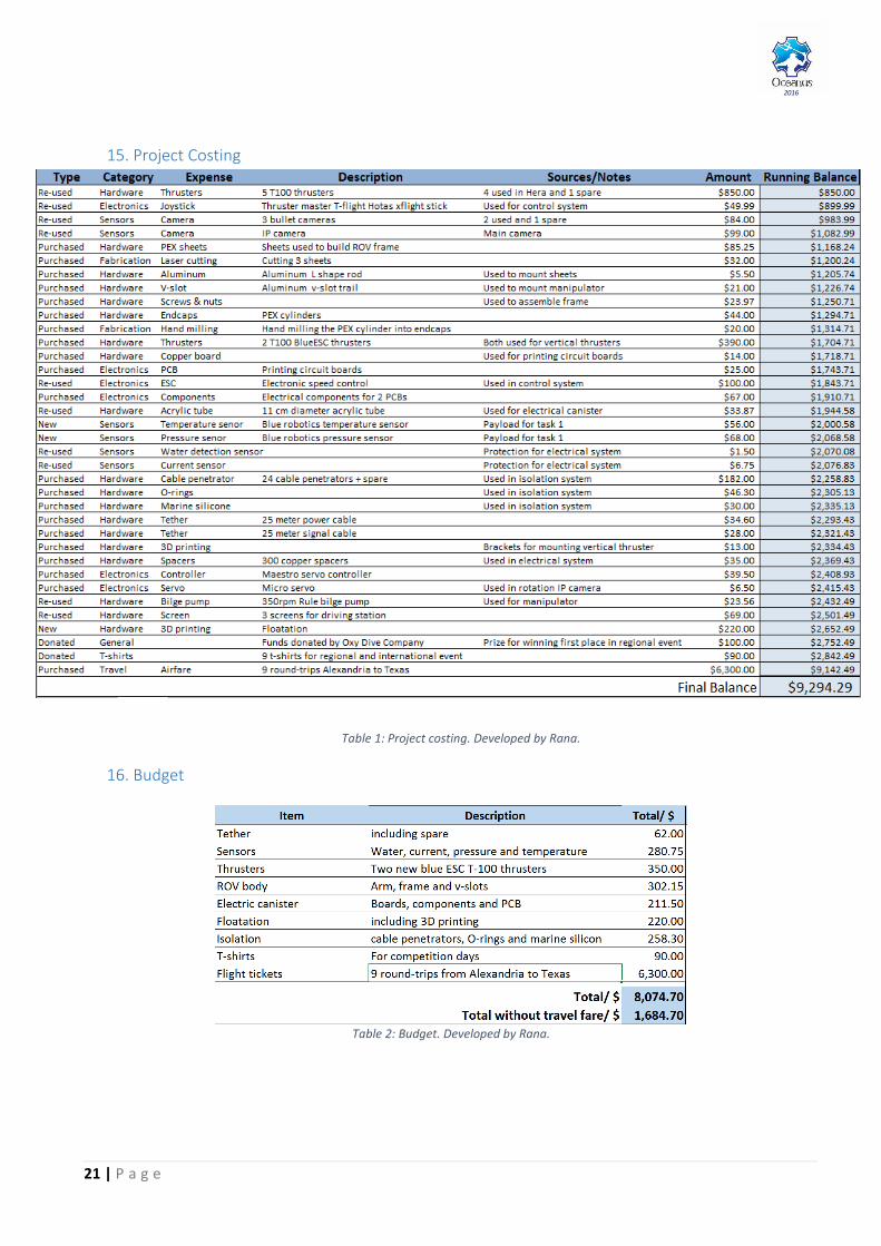
15. Project Costing
Table 1: Project costing. Developed by Rana.
16. Budget
Table 2: Budget. Developed by Rana.
22 | P a g e
2016
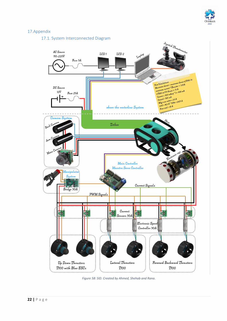
17.Appendix
17.1. System Interconnected Diagram
Figure 58: SID. Created by Ahmed, Shehab and Rana.

23 | P a g e
2016
17.2. Motor Comparison Table
Table 3: Motor comparison. Developed by the electrical engineers throughout the years.
24 | P a g e
2016
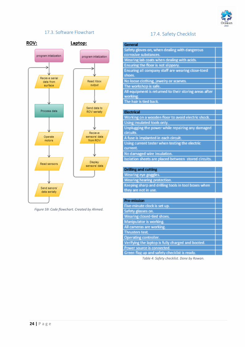
17.3. Software Flowchart
Figure 59: Code flowchart. Created by Ahmed.
17.4. Safety Checklist
Table 4: Safety checklist. Done by Rowan.
25 | P a g e
2016
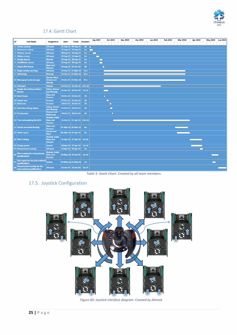
17.4. Gantt Chart
Table 5: Gantt Chart. Created by all team members.
17.5. Joystick Configuration
Figure 60: Joystick interface diagram. Created by Ahmed.