Embed Size (px)
Citation preview
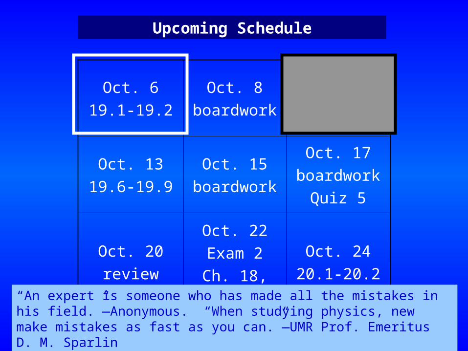
Oct. 619.1-19.2
Oct. 8boardwork
Oct. 1019.3-19.5
Quiz 4
Oct. 1319.6-19.9
Oct. 15boardwork
Oct. 17boardwork
Quiz 5
Oct. 20review
Oct. 22Exam 2
Ch. 18, 19
Oct. 2420.1-20.2
Upcoming Schedule
“An expert is someone who has made all the mistakes in his field.”—Anonymous. “When studying physics, new make mistakes as fast as you can.”—UMR Prof. Emeritus D. M. Sparlin
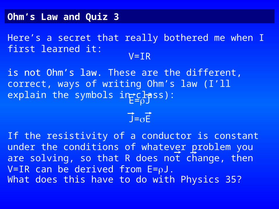
Ohm’s Law and Quiz 3
Here’s a secret that really bothered me when I first learned it:
V=IR
is not Ohm’s law.
What does this have to do with Physics 35?
E=J
J=E
If the resistivity of a conductor is constant under the conditions of whatever problem you are solving, so that R does not change, then V=IR can be derived from E=J.
is not Ohm’s law. These are the different, correct, ways of writing Ohm’s law (I’ll explain the symbols in class):
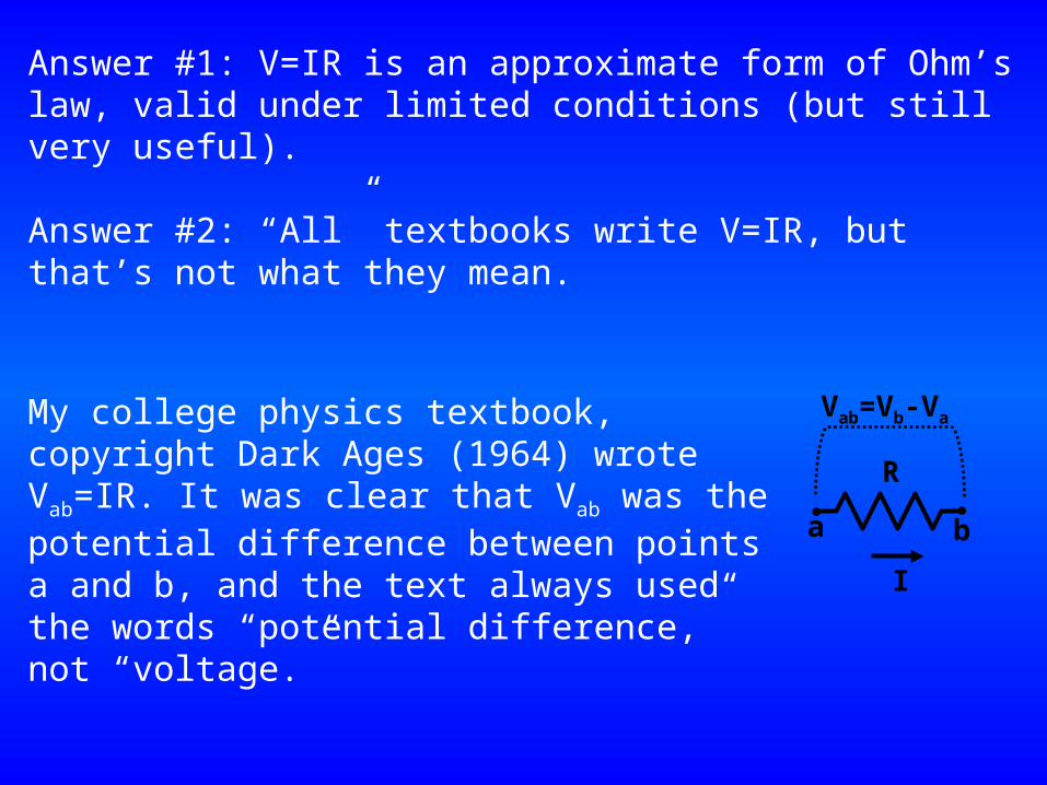
Answer #1: V=IR is an approximate form of Ohm’s law, valid under limited conditions (but still very useful).
Answer #2: “All” textbooks write V=IR, but that’s not what they mean.
My college physics textbook, copyright Dark Ages (1964) wrote Vab=IR. It was clear that Vab was the potential difference between points a and b, and the text always used the words “potential difference,” not “voltage.”
R
I
a b
Vab=Vb-Va
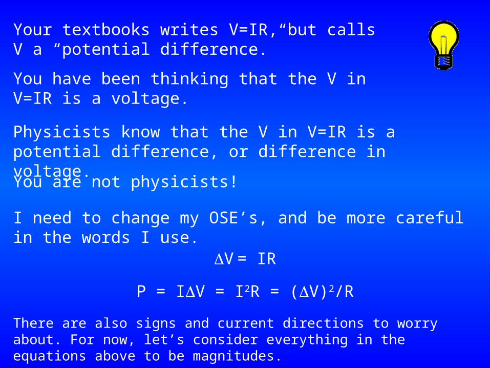
Your textbooks writes V=IR, but calls V a “potential difference.”
You have been thinking that the V in V=IR is a voltage.
Physicists know that the V in V=IR is a potential difference, or difference in voltage.
You are not physicists!
I need to change my OSE’s, and be more careful in the words I use.
V = IR
P = IV = I2R = (V)2/R
There are also signs and current directions to worry about. For now, let’s consider everything in the equations above to be magnitudes.
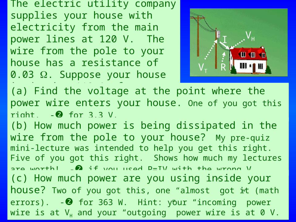
The electric utility company supplies your house with electricity from the main power lines at 120 V. The wire from the pole to your house has a resistance of 0.03 . Suppose your house is drawing 110 A of current.
VT
VHI
R
(a) Find the voltage at the point where the power wire enters your house. One of you got this right. - for 3.3 V.
(b) How much power is being dissipated in the wire from the pole to your house? My pre-quiz mini-lecture was intended to help you get this right. Five of you got this right. Shows how much my lectures are worth! - if you used P=IV with the wrong V.(c) How much power are you using inside your house? Two of you got this, one “almost” got it (math errors). - for 363 W. Hint: your “incoming” power wire is at VH and your “outgoing” power wire is at 0 V.
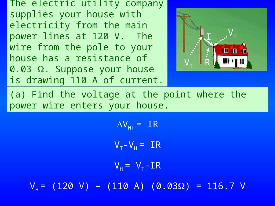
The electric utility company supplies your house with electricity from the main power lines at 120 V. The wire from the pole to your house has a resistance of 0.03 . Suppose your house is drawing 110 A of current.
VT
VHI
R
(a) Find the voltage at the point where the power wire enters your house.
VHT = IR
VT-VH = IR
VH = VT-IR
VH = (120 V) – (110 A) (0.03) = 116.7 V
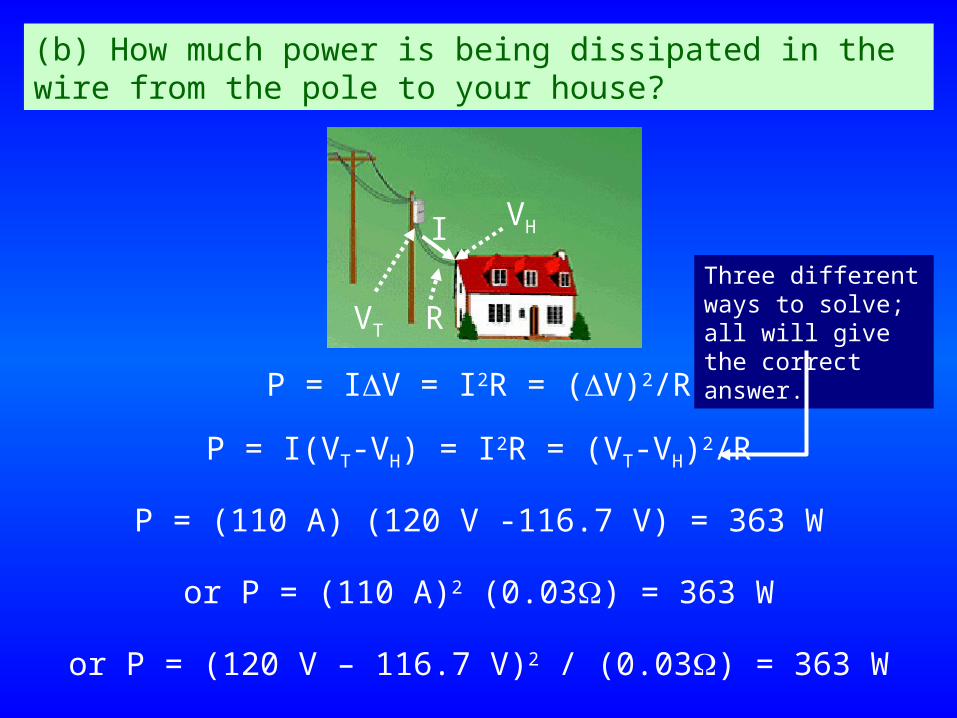
(b) How much power is being dissipated in the wire from the pole to your house?
VT
VHI
R
P = IV = I2R = (V)2/R
P = I(VT-VH) = I2R = (VT-VH)2/R
P = (110 A) (120 V -116.7 V) = 363 W
or P = (110 A)2 (0.03) = 363 W
or P = (120 V – 116.7 V)2 / (0.03) = 363 W
Three different ways to solve; all will give the correct answer.
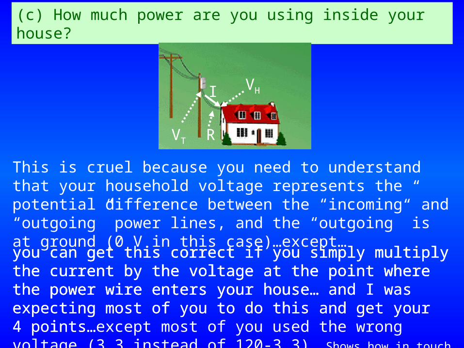
(c) How much power are you using inside your house?
VT
VHI
R
This is cruel because you need to understand that your household voltage represents the potential difference between the “incoming” and “outgoing” power lines, and the “outgoing” is at ground (0 V in this case)…except…you can get this correct if you simply multiply the current by the voltage at the point where the power wire enters your house…
you can get this correct if you simply multiply the current by the voltage at the point where the power wire enters your house… and I was expecting most of you to do this and get your 4 points…
you can get this correct if you simply multiply the current by the voltage at the point where the power wire enters your house… and I was expecting most of you to do this and get your 4 points…except most of you used the wrong voltage (3.3 instead of 120-3.3). Shows how in touch I am with what you are actually learning!
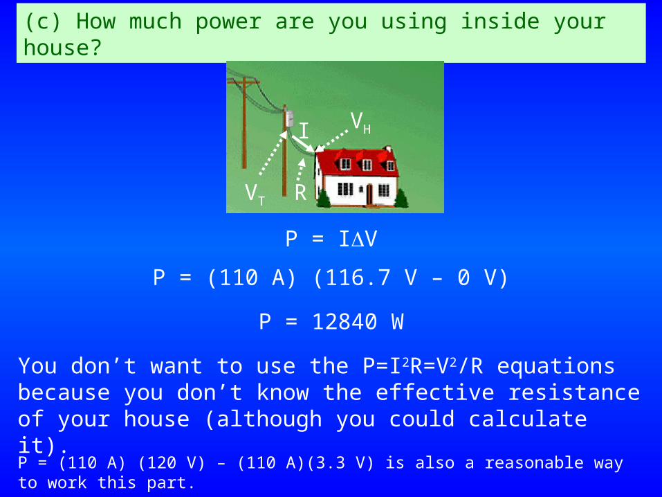
P = IV
(c) How much power are you using inside your house?
VT
VHI
R
P = (110 A) (116.7 V – 0 V)
P = 12840 W
You don’t want to use the P=I2R=V2/R equations because you don’t know the effective resistance of your house (although you could calculate it).
P = (110 A) (120 V) – (110 A)(3.3 V) is also a reasonable way to work this part.
I have one day on the schedule to do a lecture which has grown to 53 slides.
What are the chances I’ll finish today’s lecture?
If I do finish today’s lecture, what are the chances you’ll remember any of it?
Exam 2 is scheduled for Wednesday, October 22. We’ll have to keep a close watch on our schedule.
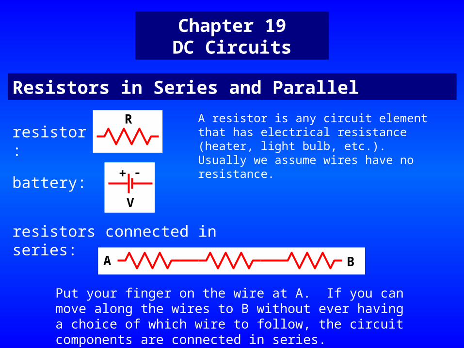
Chapter 19DC Circuits
Resistors in Series and Parallel
resistor:
resistors connected in series:
battery:+ -
V
R
A B
Put your finger on the wire at A. If you can move along the wires to B without ever having a choice of which wire to follow, the circuit components are connected in series.
A resistor is any circuit element that has electrical resistance (heater, light bulb, etc.). Usually we assume wires have no resistance.
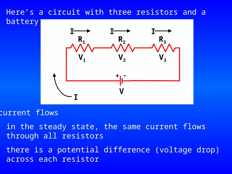
Here’s a circuit with three resistors and a battery:
R3R2R1
+ -
VI
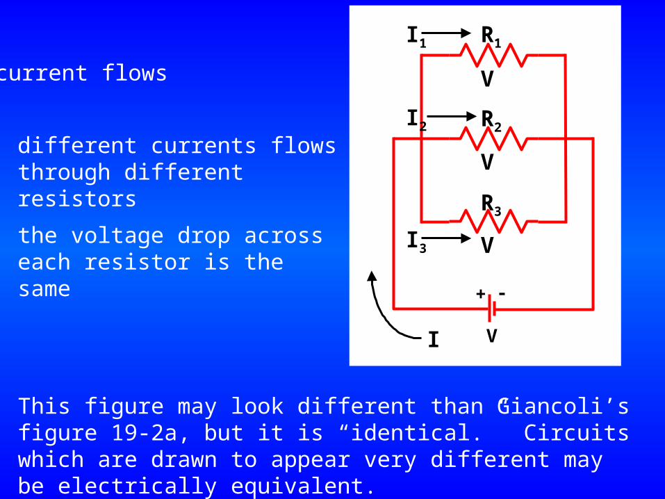
current flows
in the steady state, the same current flows through all resistors
III
there is a potential difference (voltage drop) across each resistor
V1 V3V2
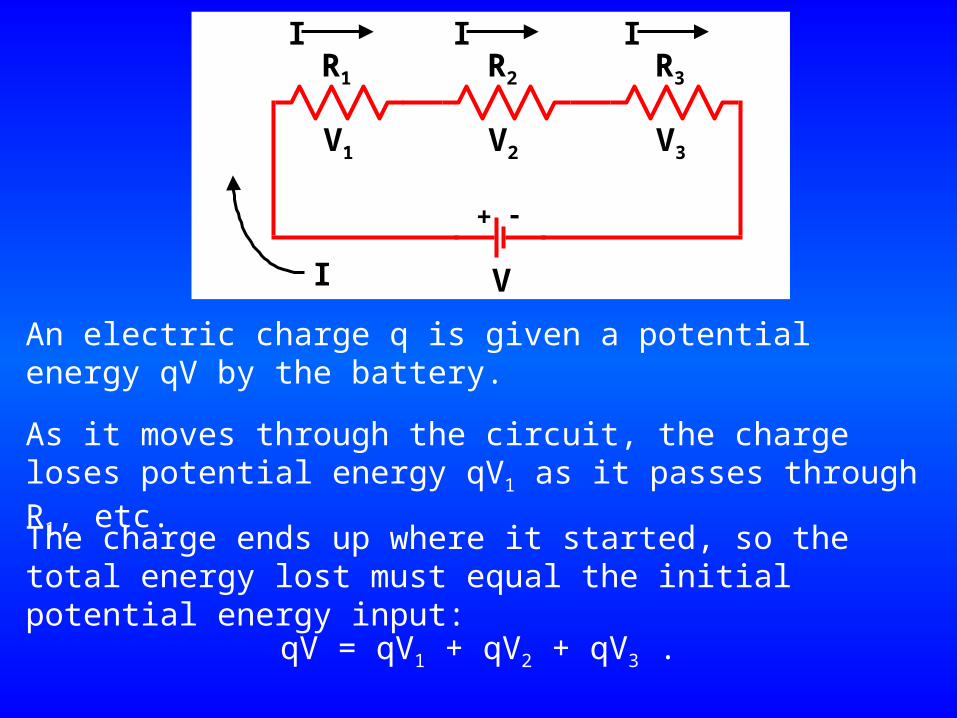
An electric charge q is given a potential energy qV by the battery.
R3R2R1
+ -
VI
III
V1 V3V2
As it moves through the circuit, the charge loses potential energy qV1 as it passes through R1, etc.
The charge ends up where it started, so the total energy lost must equal the initial potential energy input:
qV = qV1 + qV2 + qV3 .
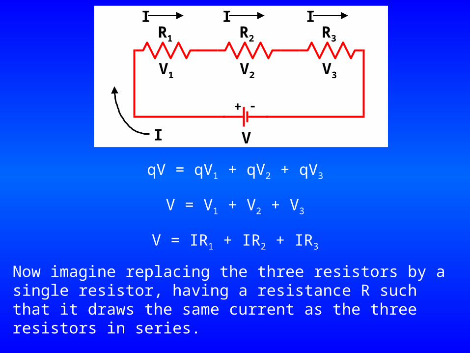
qV = qV1 + qV2 + qV3
V = V1 + V2 + V3
V = IR1 + IR2 + IR3
Now imagine replacing the three resistors by a single resistor, having a resistance R such that it draws the same current as the three resistors in series.
R3R2R1
+ -
VI
III
V1 V3V2
Req
+ -
VI
V
I
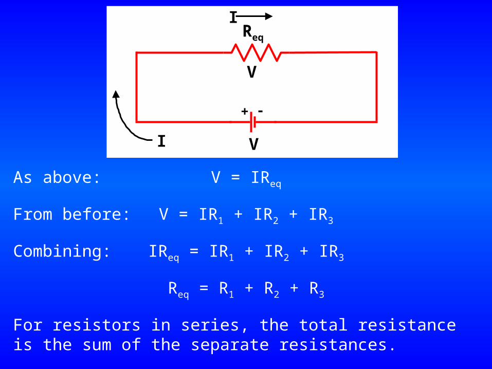
As above: V = IReq
From before: V = IR1 + IR2 + IR3
Combining: IReq = IR1 + IR2 + IR3
Req = R1 + R2 + R3
For resistors in series, the total resistance is the sum of the separate resistances.
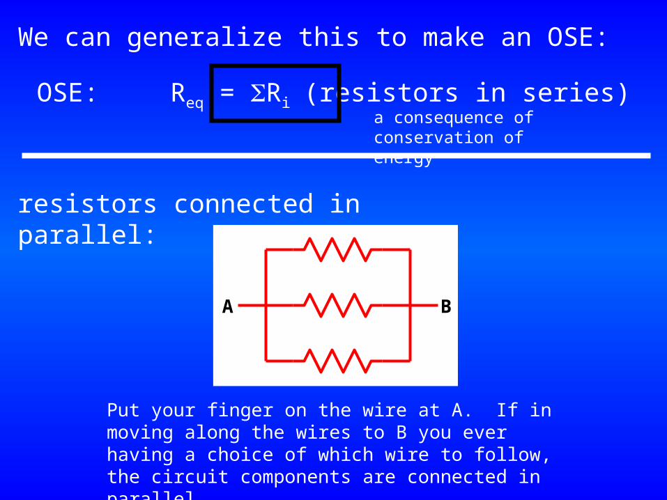
We can generalize this to make an OSE:
OSE: Req = Ri (resistors in series)
resistors connected in parallel:
A B
Put your finger on the wire at A. If in moving along the wires to B you ever having a choice of which wire to follow, the circuit components are connected in parallel.
a consequence of conservation of energy
V
V
V
R3
R2
R1
+ -
VI
current flows
different currents flows through different resistors
the voltage drop across each resistor is the same
I3
I1
I2
This figure may look different than Giancoli’s figure 19-2a, but it is “identical.” Circuits which are drawn to appear very different may be electrically equivalent.
V
V
V
R3
R2
R1
+ -
VI
I3
I1
I2A B
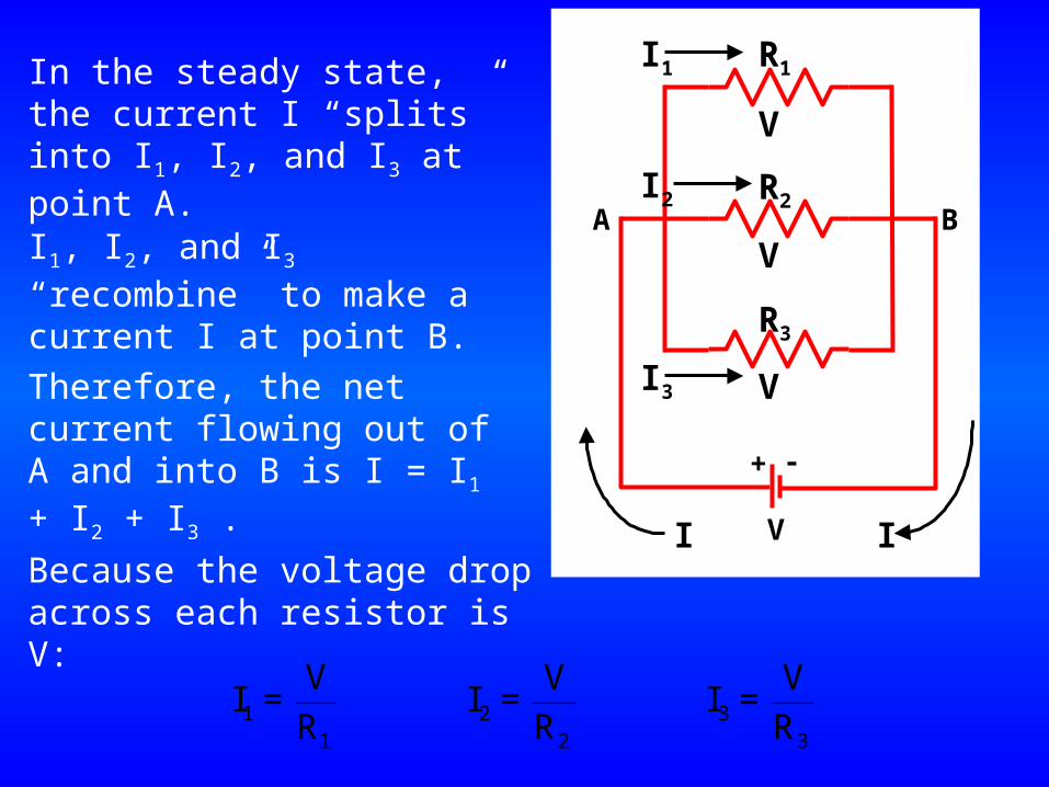
In the steady state, the current I “splits” into I1, I2, and I3 at point A.
I
I1, I2, and I3 “recombine” to make a current I at point B.
Therefore, the net current flowing out of A and into B is I = I1 + I2 + I3 .
1 2 31 2 3
V V VI = I = I =
R R R
Because the voltage drop across each resistor is V:
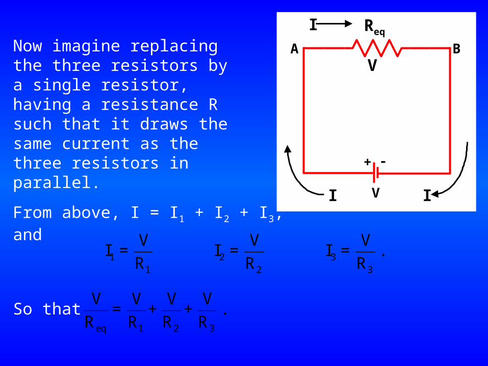
Now imagine replacing the three resistors by a single resistor, having a resistance R such that it draws the same current as the three resistors in parallel.
V
Req
+ -
VI
I
A B
IFrom above, I = I1 + I2 + I3, and
1 2 31 2 3
V V VI = I = I = .
R R R
So thateq 1 2 3
V V V V = + + .
R R R R
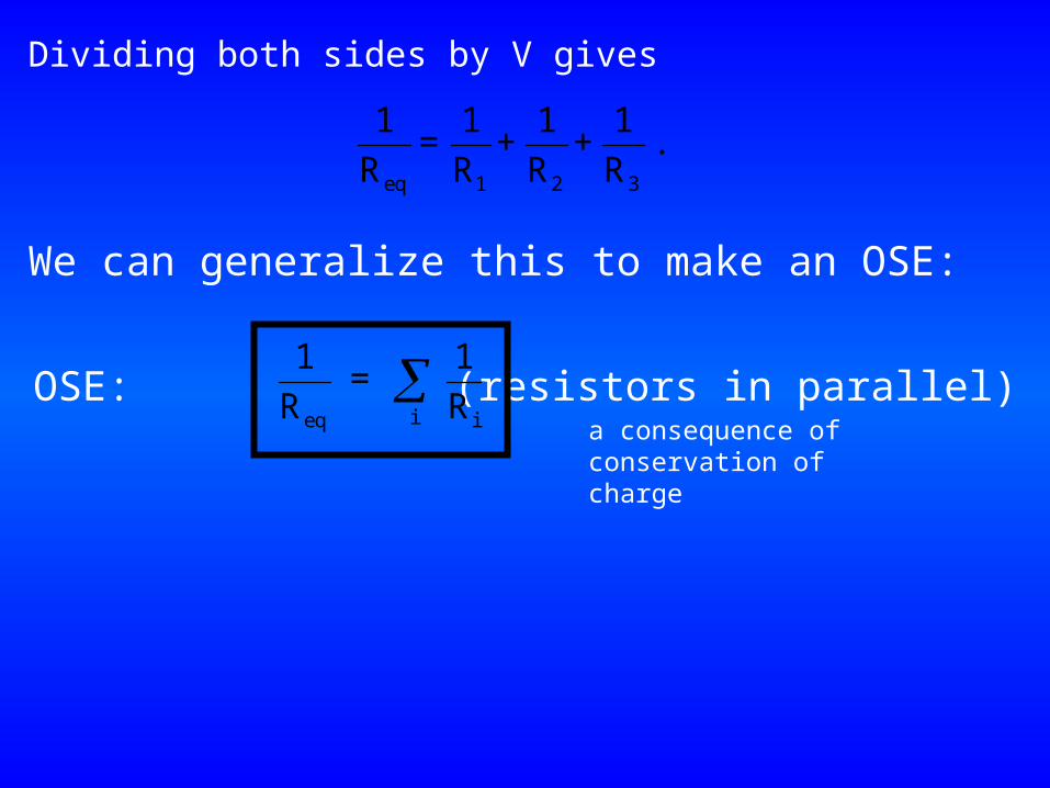
Dividing both sides by V gives
eq 1 2 3
1 1 1 1 = + + .
R R R R
We can generalize this to make an OSE:
OSE: (resistors in parallel)ieq i
1 1 =
R Ra consequence of conservation of charge
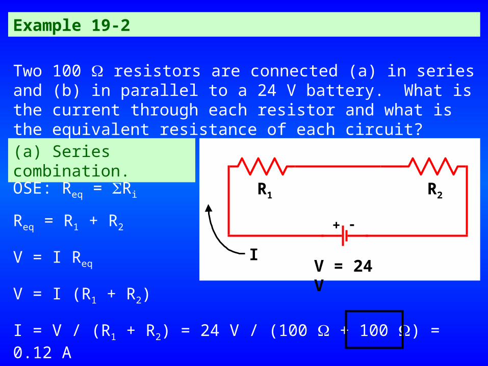
Example 19-2
Two 100 resistors are connected (a) in series and (b) in parallel to a 24 V battery. What is the current through each resistor and what is the equivalent resistance of each circuit?(a) Series combination.
R2R1
+ -
IV = 24 V
OSE: Req = Ri
Req = R1 + R2
V = I Req
V = I (R1 + R2)
I = V / (R1 + R2) = 24 V / (100 + 100 ) = 0.12 A
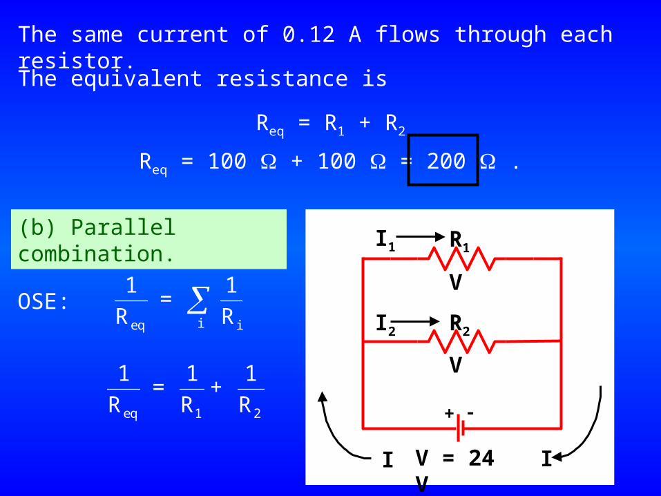
The same current of 0.12 A flows through each resistor.
The equivalent resistance is
Req = R1 + R2
Req = 100 + 100 = 200 .
(b) Parallel combination.
V
V
R2
R1
+ -
V = 24 VI
I2
I1
I
OSE:ieq i
1 1 =
R R
eq 1 2
1 1 1 = +
R R R
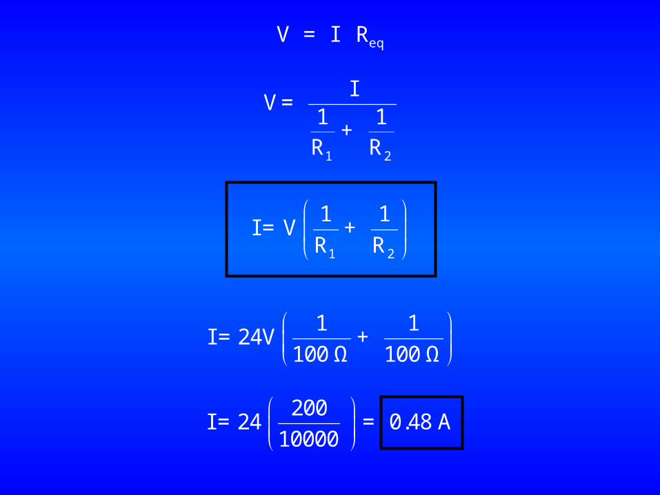
V = I Req
1 2
IV=
1 1 +
R R
1 2
1 1I = V +
R R
1 1I = 24V +
100 Ω 100 Ω
200I = 24 = 0.48 A
10000
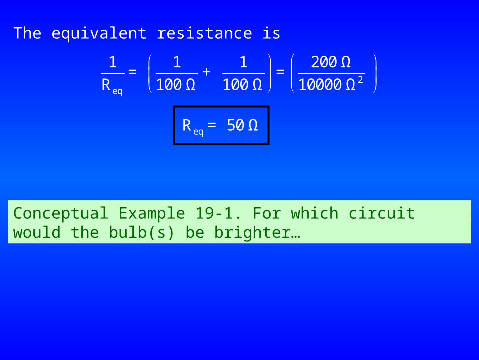
2eq
1 1 1 200 Ω= + =
R 100 Ω 100 Ω 10000 Ω
The equivalent resistance is
eqR = 50 Ω
Conceptual Example 19-1. For which circuit would the bulb(s) be brighter…
R2R1
+ -
IV = 24 V
V
V
R2
R1
+ -
V = 24 VI
I2
I1
I
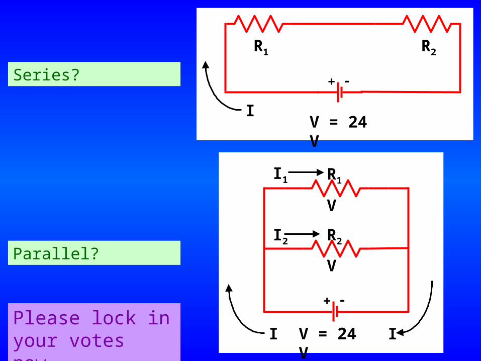
Series?
Parallel?
Please lock in your votes now.
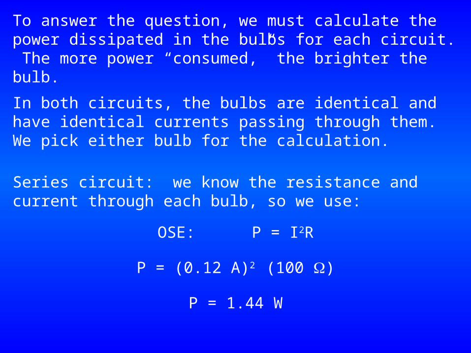
To answer the question, we must calculate the power dissipated in the bulbs for each circuit. The more power “consumed,” the brighter the bulb.
In both circuits, the bulbs are identical and have identical currents passing through them. We pick either bulb for the calculation.
Series circuit: we know the resistance and current through each bulb, so we use:
OSE: P = I2R
P = (0.12 A)2 (100 )
P = 1.44 W
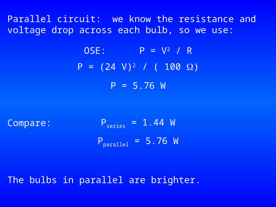
Parallel circuit: we know the resistance and voltage drop across each bulb, so we use:
OSE: P = V2 / R
P = (24 V)2 / ( 100 )
Compare: Pseries = 1.44 W
Pparallel = 5.76 W
The bulbs in parallel are brighter.
P = 5.76 W
The hands-on activity we did failed to “prove” to all groups that the lamps are brighter in parallel than in series.Why?
The calculation assumes the voltage of the battery remains constant.
Some of the batteries I have have been used many times over the last 5 years (or more). They last a very long time when used with the little light bulbs. Nevertheless, the do “wear out.” I should have replaced them with new ones.The calculation above shows 4 times as much current flows in the parallel circuit compared to the series circuit.
You may have also noticed that when you first connected the parallel circuit, the lights were dim, and then they got brighter after a while.
This is another sympton of dying batteries.
The reason for the misbehaving circuits is that the batteries, as they near the end of their lifetime, are not able to deliver their full rated voltage, especially under heavy load conditions. Hence the current and bulb brightness is noticeably reduced in the parallel circuit.
Don’t believe me? Then I’ll have to bring in fresh batteries some time and demonstrate.
Here are some on-line toys:
Light bulbs in series and parallel. (seems to be dead)The Ohm Zone. You can build your own circuits.Science Joy Wagon. Lessons on electricity. (now a pay site)
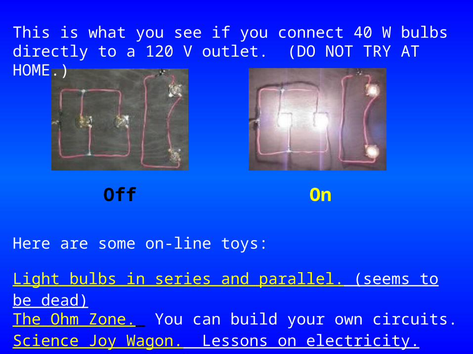
This is what you see if you connect 40 W bulbs directly to a 120 V outlet. (DO NOT TRY AT HOME.)
Off On