Embed Size (px)
Citation preview

Codeware, Inc.
Houston, TX, USA
www.codeware.com
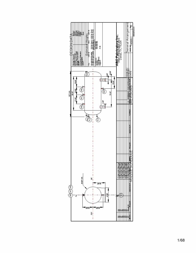
COMPRESS Pressure Vessel Design Calculations
Item: Split Stream DearatorVessel No: V-1234Customer: Magaladon Oil Venture
Contract: C-45490-R56Designer: John Doe
Date: April 1, 2001
You can edit this page by selecting Cover Page settings... in the report menu.
1/68

Deficiencies Summary
No deficiencies found.
2/68
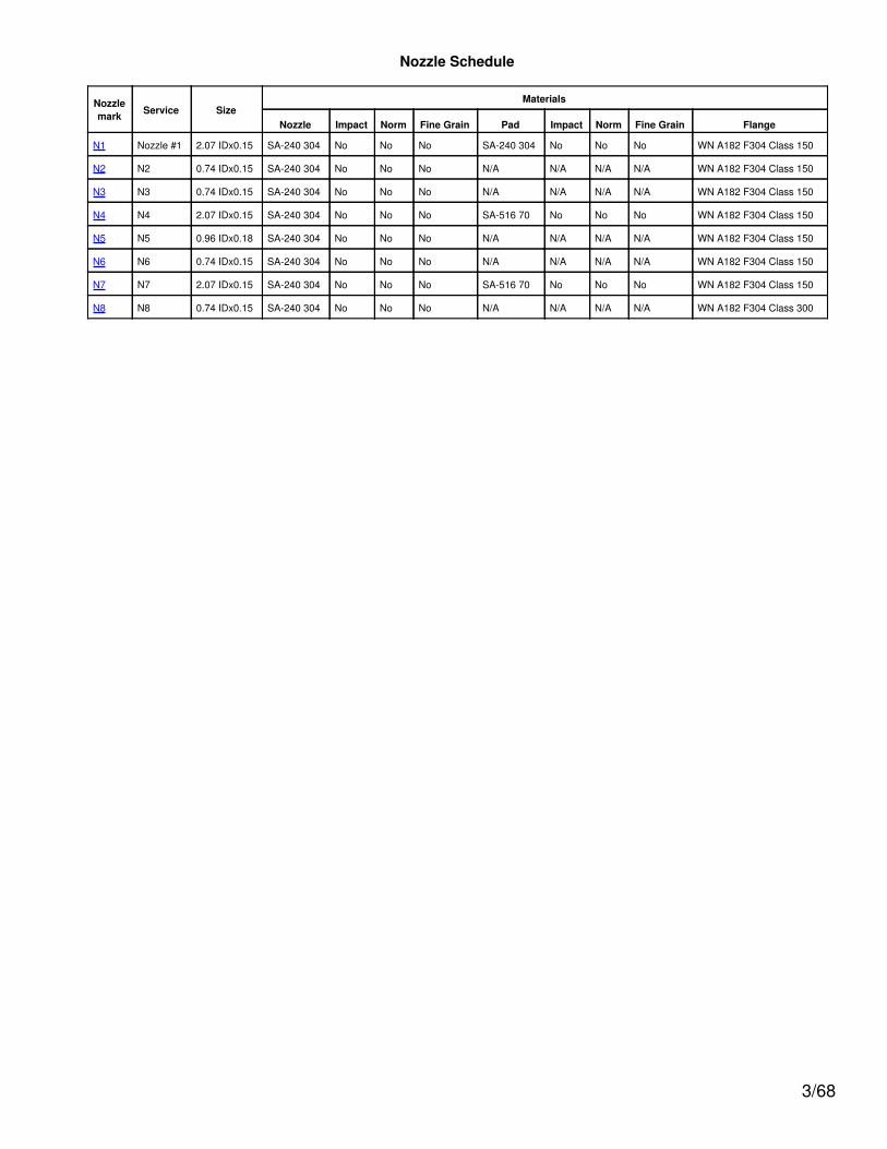
Nozzle Schedule
Nozzlemark Service Size
Materials
Nozzle Impact Norm Fine Grain Pad Impact Norm Fine Grain Flange
N1 Nozzle #1 2.07 IDx0.15 SA-240 304 No No No SA-240 304 No No No WN A182 F304 Class 150
N2 N2 0.74 IDx0.15 SA-240 304 No No No N/A N/A N/A N/A WN A182 F304 Class 150
N3 N3 0.74 IDx0.15 SA-240 304 No No No N/A N/A N/A N/A WN A182 F304 Class 150
N4 N4 2.07 IDx0.15 SA-240 304 No No No SA-516 70 No No No WN A182 F304 Class 150
N5 N5 0.96 IDx0.18 SA-240 304 No No No N/A N/A N/A N/A WN A182 F304 Class 150
N6 N6 0.74 IDx0.15 SA-240 304 No No No N/A N/A N/A N/A WN A182 F304 Class 150
N7 N7 2.07 IDx0.15 SA-240 304 No No No SA-516 70 No No No WN A182 F304 Class 150
N8 N8 0.74 IDx0.15 SA-240 304 No No No N/A N/A N/A N/A WN A182 F304 Class 300
3/68
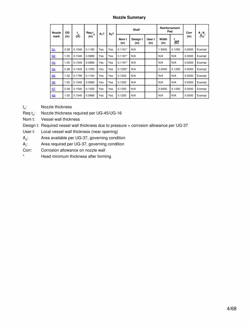
Nozzle Summary
Nozzlemark
OD(in)
tn
(in)Req t
n(in)
A1? A2?Shell Reinforcement
Pad Corr(in)
Aa/A
r(%)
Nom t(in)
Design t(in)
User t(in)
Width(in)
tpad(in)
N1 2.38 0.1540 0.1180 Yes Yes 0.1181* N/A 1.5000 0.1250 0.0000 Exempt
N2 1.05 0.1540 0.0989 Yes Yes 0.1181* N/A N/A N/A 0.0000 Exempt
N3 1.05 0.1540 0.0989 Yes Yes 0.1181* N/A N/A N/A 0.0000 Exempt
N4 2.38 0.1540 0.1250 Yes Yes 0.1250* N/A 2.0000 0.1250 0.0000 Exempt
N5 1.32 0.1790 0.1164 Yes Yes 0.1250 N/A N/A N/A 0.0000 Exempt
N6 1.05 0.1540 0.0989 Yes Yes 0.1250 N/A N/A N/A 0.0000 Exempt
N7 2.38 0.1540 0.1250 Yes Yes 0.1250 N/A 2.0000 0.1250 0.0000 Exempt
N8 1.05 0.1540 0.0989 Yes Yes 0.1250 N/A N/A N/A 0.0000 Exempt
tn: Nozzle thicknessReq tn: Nozzle thickness required per UG-45/UG-16Nom t: Vessel wall thicknessDesign t: Required vessel wall thickness due to pressure + corrosion allowance per UG-37User t: Local vessel wall thickness (near opening)Aa: Area available per UG-37, governing conditionAr: Area required per UG-37, governing conditionCorr: Corrosion allowance on nozzle wall* Head minimum thickness after forming
4/68
Pressure Summary
Pressure Summary for Chamber bounded by Ellipsoidal Head #1 and Ellipsoidal Head #2
IdentifierP
Design( psi)
T
Design(°F)
MAWP( psi)
MAP( psi)
MDMT(°F)
MDMTExemption
Total Corrosion
Allowance(in)
ImpactTest
Ellipsoidal Head #2 50.0 158.0 98.85 98.85 -320.0 Note 1 0.000 No
Straight Flange on Ellipsoidal Head #2 50.0 158.0 98.61 98.61 -320.0 Note 2 0.000 No
Cylinder #1 50.0 158.0 104.38 104.38 -320.0 Note 2 0.000 No
Straight Flange on Ellipsoidal Head #1 50.0 158.0 104.38 104.38 -320.0 Note 2 0.000 No
Ellipsoidal Head #1 50.0 158.0 104.66 104.66 -320.0 Note 1 0.000 No
Saddle #1 50.0 158.0 98.61 N/A N/A N/A N/A N/A
Nozzle #1 (N1) 50.0 158.0 98.81 98.81 -55.0 Nozzle Note 3; Pad Note 2 0.000 No
N2 (N2) 50.0 158.0 109.59 109.59 -55.0 Note 3 0.000 No
N3 (N3) 50.0 158.0 109.59 109.59 -55.0 Note 3 0.000 No
N4 (N4) 50.0 158.0 104.66 104.66 -25.8 Nozzle Note 2; Pad Note 4 0.000 No
N5 (N5) 50.0 158.0 104.35 104.35 -55.0 Note 3 0.000 No
N6 (N6) 50.0 158.0 104.35 104.35 -55.0 Note 3 0.000 No
N7 (N7) 50.0 158.0 104.35 104.35 -25.5 Nozzle Note 2; Pad Note 5 0.000 No
N8 (N8) 50.0 158.0 104.35 104.35 -55.0 Note 3 0.000 No
Chamber design MDMT is -20.00°FChamber rated MDMT is -25.50°F @ 98.61 psiChamber MAWP was used in the MDMT determination
Chamber MAWP hot & corroded is 98.61 psi @ 158.0°F
Chamber MAP cold & new is 98.61 psi @ 70.0°F
This pressure chamber is not designed for external pressure.
Notes for MDMT Rating:
Note # Exemption Details
1. Material Rated MDMT per UHA-51(d)(1)(a) = -320 °F
2. Rated MDMT per UHA-51(d)(1)(a) = -320 °F
3.Flange rating governs:Flange rated MDMT = -320 °FBolts rated MDMT per Fig UCS-66 note (e) = -55 °F
Per UHA-51(d)(1)(a)
4. Pad impact test exemption temperature from Fig UCS-66 Curve B = -20 °FFig UCS-66.1 MDMT reduction = 5.8 °F, (coincident ratio = 0.94248) UCS-66 governing thickness = 0.125 in.
5. Pad impact test exemption temperature from Fig UCS-66 Curve B = -20 °FFig UCS-66.1 MDMT reduction = 5.5 °F, (coincident ratio = 0.9448) UCS-66 governing thickness = 0.125 in.
Design notes are available on the Settings Summary page.
5/68
Revision History
No. Date Operator Notes
0 7/ 5/2013 User New vessel created ASME Section VIII Division 1 [Build 6258]
6/68
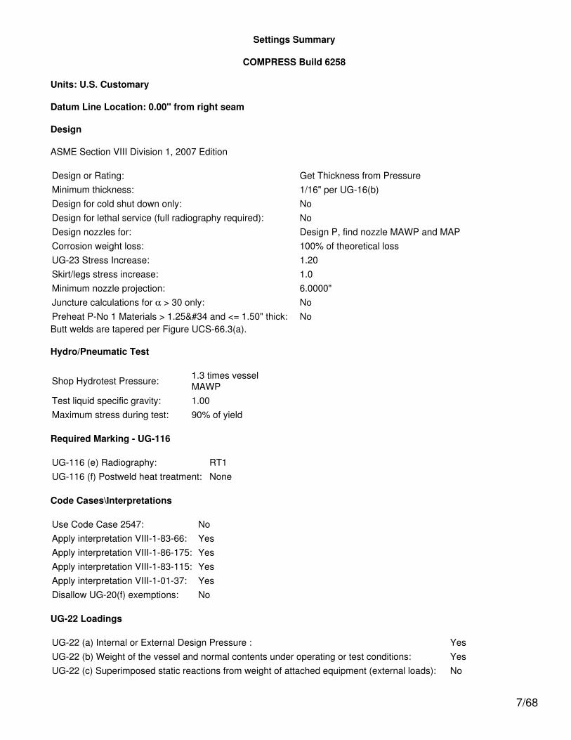
Settings Summary
COMPRESS Build 6258
Units: U.S. Customary
Datum Line Location: 0.00" from right seam
Design
ASME Section VIII Division 1, 2007 Edition
Design or Rating: Get Thickness from PressureMinimum thickness: 1/16" per UG-16(b)Design for cold shut down only: NoDesign for lethal service (full radiography required): NoDesign nozzles for: Design P, find nozzle MAWP and MAPCorrosion weight loss: 100% of theoretical lossUG-23 Stress Increase: 1.20Skirt/legs stress increase: 1.0Minimum nozzle projection: 6.0000"Juncture calculations for α > 30 only: NoPreheat P-No 1 Materials > 1.25" and <= 1.50" thick: NoButt welds are tapered per Figure UCS-66.3(a).
Hydro/Pneumatic Test
Shop Hydrotest Pressure: 1.3 times vesselMAWP
Test liquid specific gravity: 1.00Maximum stress during test: 90% of yield
Required Marking - UG-116
UG-116 (e) Radiography: RT1UG-116 (f) Postweld heat treatment: None
Code Cases\Interpretations
Use Code Case 2547: NoApply interpretation VIII-1-83-66: YesApply interpretation VIII-1-86-175: YesApply interpretation VIII-1-83-115: YesApply interpretation VIII-1-01-37: YesDisallow UG-20(f) exemptions: No
UG-22 Loadings
UG-22 (a) Internal or External Design Pressure : YesUG-22 (b) Weight of the vessel and normal contents under operating or test conditions: YesUG-22 (c) Superimposed static reactions from weight of attached equipment (external loads): No
7/68
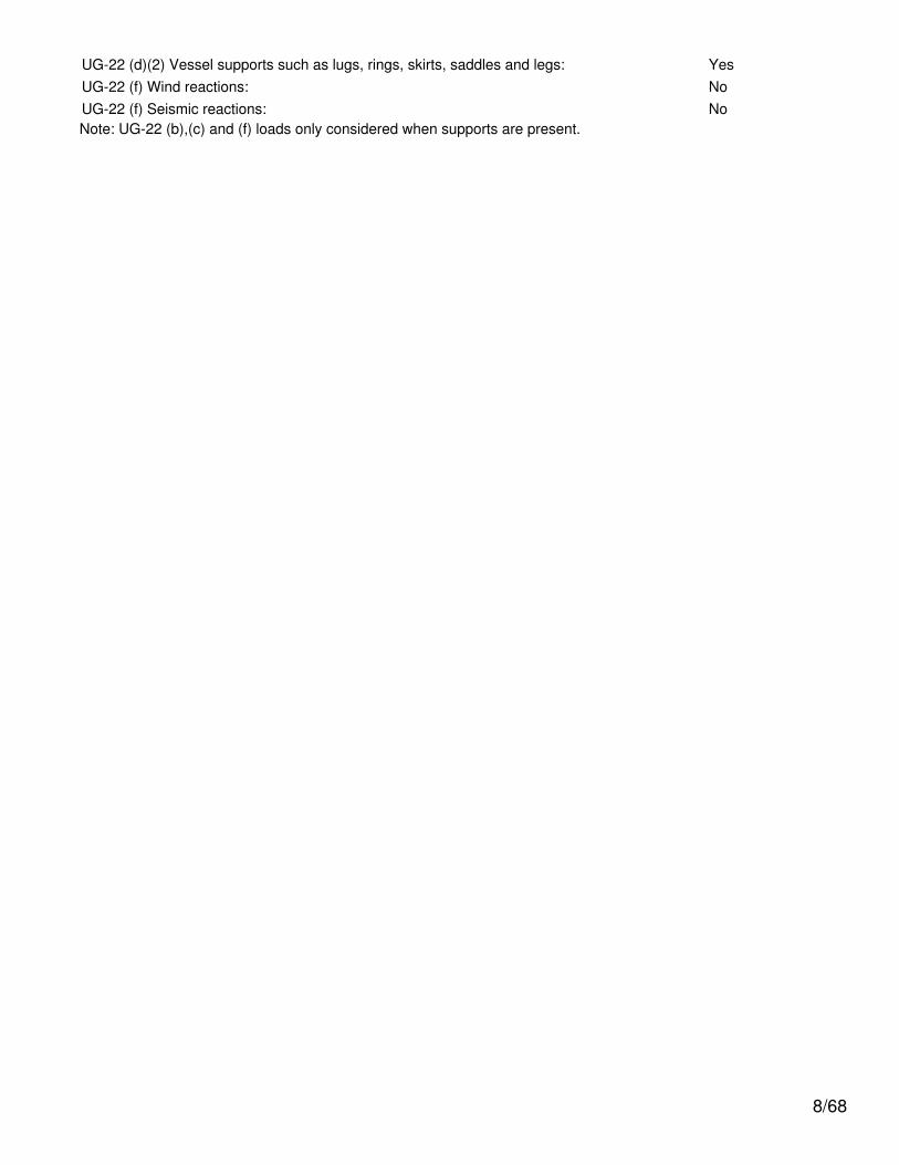
UG-22 (d)(2) Vessel supports such as lugs, rings, skirts, saddles and legs: YesUG-22 (f) Wind reactions: NoUG-22 (f) Seismic reactions: NoNote: UG-22 (b),(c) and (f) loads only considered when supports are present.
8/68
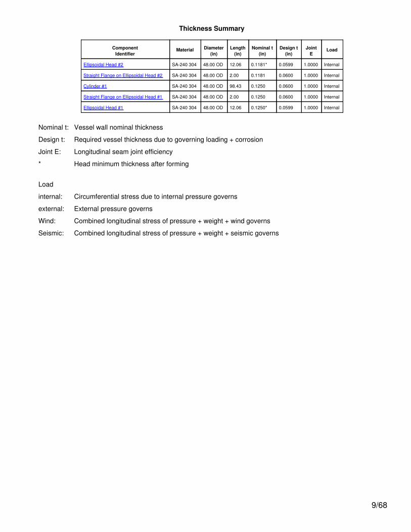
Thickness Summary
ComponentIdentifier
Material Diameter(in)
Length(in)
Nominal t(in)
Design t(in)
JointE
Load
Ellipsoidal Head #2 SA-240 304 48.00 OD 12.06 0.1181* 0.0599 1.0000 Internal
Straight Flange on Ellipsoidal Head #2 SA-240 304 48.00 OD 2.00 0.1181 0.0600 1.0000 Internal
Cylinder #1 SA-240 304 48.00 OD 98.43 0.1250 0.0600 1.0000 Internal
Straight Flange on Ellipsoidal Head #1 SA-240 304 48.00 OD 2.00 0.1250 0.0600 1.0000 Internal
Ellipsoidal Head #1 SA-240 304 48.00 OD 12.06 0.1250* 0.0599 1.0000 Internal
Nominal t: Vessel wall nominal thickness
Design t: Required vessel thickness due to governing loading + corrosion
Joint E: Longitudinal seam joint efficiency
* Head minimum thickness after forming
Load
internal: Circumferential stress due to internal pressure governs
external: External pressure governs
Wind: Combined longitudinal stress of pressure + weight + wind governs
Seismic: Combined longitudinal stress of pressure + weight + seismic governs
9/68
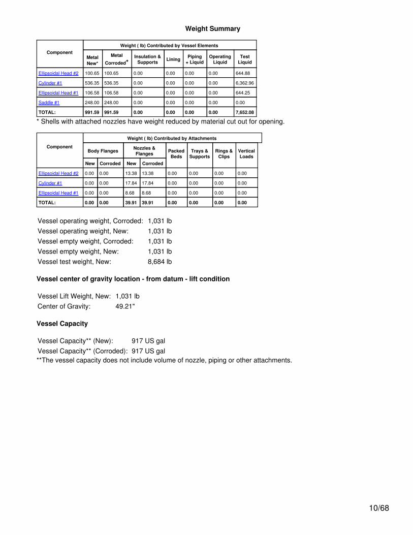
Weight Summary
ComponentWeight ( lb) Contributed by Vessel Elements
MetalNew*
Metal
Corroded*Insulation &
Supports Lining Piping+ Liquid
OperatingLiquid
TestLiquid
Ellipsoidal Head #2 100.65 100.65 0.00 0.00 0.00 0.00 644.88
Cylinder #1 536.35 536.35 0.00 0.00 0.00 0.00 6,362.96
Ellipsoidal Head #1 106.58 106.58 0.00 0.00 0.00 0.00 644.25
Saddle #1 248.00 248.00 0.00 0.00 0.00 0.00 0.00
TOTAL: 991.59 991.59 0.00 0.00 0.00 0.00 7,652.08
* Shells with attached nozzles have weight reduced by material cut out for opening.
Component
Weight ( lb) Contributed by Attachments
Body Flanges Nozzles &Flanges Packed
BedsTrays &
SupportsRings &
ClipsVerticalLoads
New Corroded New Corroded
Ellipsoidal Head #2 0.00 0.00 13.38 13.38 0.00 0.00 0.00 0.00
Cylinder #1 0.00 0.00 17.84 17.84 0.00 0.00 0.00 0.00
Ellipsoidal Head #1 0.00 0.00 8.68 8.68 0.00 0.00 0.00 0.00
TOTAL: 0.00 0.00 39.91 39.91 0.00 0.00 0.00 0.00
Vessel operating weight, Corroded: 1,031 lbVessel operating weight, New: 1,031 lbVessel empty weight, Corroded: 1,031 lbVessel empty weight, New: 1,031 lbVessel test weight, New: 8,684 lb
Vessel center of gravity location - from datum - lift condition
Vessel Lift Weight, New: 1,031 lbCenter of Gravity: 49.21"
Vessel Capacity
Vessel Capacity** (New): 917 US galVessel Capacity** (Corroded): 917 US gal**The vessel capacity does not include volume of nozzle, piping or other attachments.
10/68
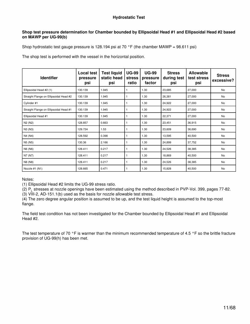
Hydrostatic Test
Shop test pressure determination for Chamber bounded by Ellipsoidal Head #1 and Ellipsoidal Head #2 basedon MAWP per UG-99(b)
Shop hydrostatic test gauge pressure is 128.194 psi at 70 °F (the chamber MAWP = 98.611 psi)
The shop test is performed with the vessel in the horizontal position.
IdentifierLocal testpressure
psi
Test liquidstatic head
psi
UG-99stressratio
UG-99pressure
factor
Stressduring test
psi
Allowabletest stress
psi
Stressexcessive?
Ellipsoidal Head #2 (1) 130.139 1.945 1 1.30 23,685 27,000 No
Straight Flange on Ellipsoidal Head #2 130.139 1.945 1 1.30 26,381 27,000 No
Cylinder #1 130.139 1.945 1 1.30 24,922 27,000 No
Straight Flange on Ellipsoidal Head #1 130.139 1.945 1 1.30 24,922 27,000 No
Ellipsoidal Head #1 130.139 1.945 1 1.30 22,371 27,000 No
N2 (N2) 128.857 0.663 1 1.30 23,451 36,915 No
N3 (N3) 129.724 1.53 1 1.30 23,609 36,690 No
N4 (N4) 128.592 0.398 1 1.30 13,595 40,500 No
N5 (N5) 130.36 2.166 1 1.30 24,899 37,752 No
N6 (N6) 128.411 0.217 1 1.30 24,526 38,385 No
N7 (N7) 128.411 0.217 1 1.30 18,869 40,500 No
N8 (N8) 128.411 0.217 1 1.30 24,526 38,385 No
Nozzle #1 (N1) 128.665 0.471 1 1.30 15,828 40,500 No
Notes:(1) Ellipsoidal Head #2 limits the UG-99 stress ratio.(2) PL stresses at nozzle openings have been estimated using the method described in PVP-Vol. 399, pages 77-82.(3) VIII-2, AD-151.1(b) used as the basis for nozzle allowable test stress.(4) The zero degree angular position is assumed to be up, and the test liquid height is assumed to the top-mostflange.
The field test condition has not been investigated for the Chamber bounded by Ellipsoidal Head #1 and EllipsoidalHead #2.
The test temperature of 70 °F is warmer than the minimum recommended temperature of 4.5 °F so the brittle fractureprovision of UG-99(h) has been met.
11/68
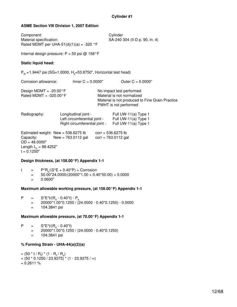
Cylinder #1
ASME Section VIII Division 1, 2007 Edition
Component: CylinderMaterial specification: SA-240 304 (II-D p. 90, ln. 4)Rated MDMT per UHA-51(d)(1)(a) = -320 °F
Internal design pressure: P = 50 psi @ 158°F
Static liquid head:
Pth =1.9447 psi (SG=1.0000, Hs=53.8750", Horizontal test head)
Corrosion allowance: Inner C = 0.0000" Outer C = 0.0000"
Design MDMT = -20.00°F No impact test performedRated MDMT = -320.00°F Material is not normalized
Material is not produced to Fine Grain PracticePWHT is not performed
Radiography: Longitudinal joint - Full UW-11(a) Type 1Left circumferential joint - Full UW-11(a) Type 1Right circumferential joint - Full UW-11(a) Type 1
Estimated weight: New = 536.6275 lb corr = 536.6275 lbCapacity: New = 763.0112 gal corr = 763.0112 galOD = 48.0000"Length Lc = 98.4252"t = 0.1250"
Design thickness, (at 158.00°F) Appendix 1-1
t = P*Ro/(S*E + 0.40*P) + Corrosion= 50.00*24.0000/(20000*1.00 + 0.40*50.00) + 0.0000= 0.0600"
Maximum allowable working pressure, (at 158.00°F) Appendix 1-1
P = S*E*t/(Ro - 0.40*t) - Ps= 20000*1.00*0.1250 / (24.0000 - 0.40*0.1250) - 0.0000= 104.3841 psi
Maximum allowable pressure, (at 70.00°F) Appendix 1-1
P = S*E*t/(Ro - 0.40*t)= 20000*1.00*0.1250 / (24.0000 - 0.40*0.1250)= 104.3841 psi
% Forming Strain - UHA-44(a)(2)(a)
= (50 * t / Rf) * (1 - Rf / Ro)= (50 * 0.1250 / 23.9375) * (1 - 23.9375 / ∞)= 0.2611 %
12/68
Allowable Compressive Stress, Hot and Corroded- ScHC, (table HA-1)A = 0.125 / (Ro / t)
= 0.125 / (24.0000 / 0.1250)= 0.000651
B = 7137.3750 psi
S = 20000.0000 / 1.0000= 20000.0000 psi
ScHC = 7137.3750 psi
Allowable Compressive Stress, Hot and New- ScHN
ScHN = ScHC
= 7137.3750 psi
Allowable Compressive Stress, Cold and New- ScCN, (table HA-1)A = 0.125 / (Ro / t)
= 0.125 / (24.0000 / 0.1250)= 0.000651
B = 7490.2925 psi
S = 20000.0000 / 1.0000= 20000.0000 psi
ScCN = 7490.2925 psi
Allowable Compressive Stress, Cold and Corroded- ScCC
ScCC = ScCN
= 7490.2925 psi
Allowable Compressive Stress, Vacuum and Corroded- ScVC, (table HA-1)A = 0.125 / (Ro / t)
= 0.125 / (24.0000 / 0.1250)= 0.000651
B = 7490.2925 psi
S = 20000.0000 / 1.0000= 20000.0000 psi
ScVC = 7490.2925 psi
13/68

Ellipsoidal Head #2
ASME Section VIII, Division 1, 2007 Edition
Component: Ellipsoidal HeadMaterial Specification: SA-240 304 (II-D p.90, ln. 4)Material Rated MDMT per UHA-51(d)(1)(a) = -320 °F
Internal design pressure: P = 50 psi @ 158 °F
Static liquid head:
Ps= 0 psi (SG=1, Hs=0" Operating head)Pth= 1.945 psi (SG=1, Hs=53.8819" Horizontal test head)
Corrosion allowance: Inner C = 0" Outer C = 0"
Design MDMT = -20°F No impact test performedRated MDMT = -320°F Material is not normalized
Material is not produced to fine grain practicePWHT is not performedDo not Optimize MDMT / Find MAWP
Radiography: Category A joints - Full UW-11(a) Type 1 Head to shell seam - Full UW-11(a) Type 1
Estimated weight*: new = 100.7 lb corr = 100.7 lbCapacity*: new = 77.3 US gal corr = 77.3 US gal* includes straight flange
Outer diameter = 48"Minimum head thickness = 0.1181"Head ratio D/2h = 2 (new)Head ratio D/2h = 2 (corroded)Straight flange length Lsf = 2"Nominal straight flange thickness tsf = 0.1181"Results Summary
The governing condition is UG-16.Minimum thickness per UG-16 = 0.0625" + 0" = 0.0625"Design thickness due to internal pressure (t) = 0.0599"Maximum allowable working pressure (MAWP) = 98.85 psiMaximum allowable pressure (MAP) = 98.85 psi
K (Corroded)
K=(1/6)*[2 + (D / (2*h))2]=(1/6)*[2 + (47.7638 / (2*11.941))2]=1
K (New)
K=(1/6)*[2 + (D / (2*h))2]=(1/6)*[2 + (47.7638 / (2*11.941))2]=1
14/68
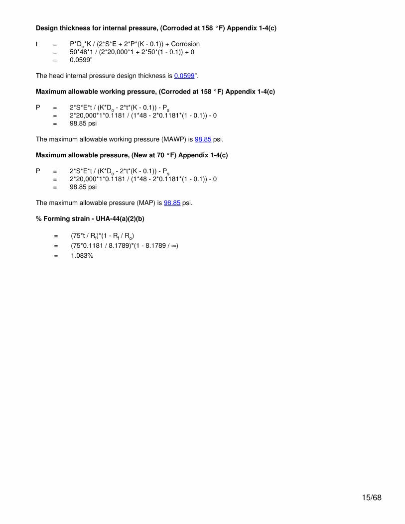
Design thickness for internal pressure, (Corroded at 158 °F) Appendix 1-4(c)
t = P*Do*K / (2*S*E + 2*P*(K - 0.1)) + Corrosion= 50*48*1 / (2*20,000*1 + 2*50*(1 - 0.1)) + 0= 0.0599"
The head internal pressure design thickness is 0.0599".
Maximum allowable working pressure, (Corroded at 158 °F) Appendix 1-4(c)
P = 2*S*E*t / (K*Do - 2*t*(K - 0.1)) - Ps= 2*20,000*1*0.1181 / (1*48 - 2*0.1181*(1 - 0.1)) - 0= 98.85 psi
The maximum allowable working pressure (MAWP) is 98.85 psi.
Maximum allowable pressure, (New at 70 °F) Appendix 1-4(c)
P = 2*S*E*t / (K*Do - 2*t*(K - 0.1)) - Ps= 2*20,000*1*0.1181 / (1*48 - 2*0.1181*(1 - 0.1)) - 0= 98.85 psi
The maximum allowable pressure (MAP) is 98.85 psi.
% Forming strain - UHA-44(a)(2)(b)
= (75*t / Rf)*(1 - Rf / Ro)= (75*0.1181 / 8.1789)*(1 - 8.1789 / ∞)= 1.083%
15/68
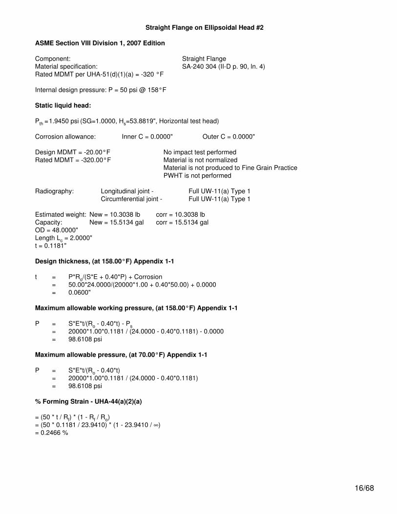
Straight Flange on Ellipsoidal Head #2
ASME Section VIII Division 1, 2007 Edition
Component: Straight FlangeMaterial specification: SA-240 304 (II-D p. 90, ln. 4)Rated MDMT per UHA-51(d)(1)(a) = -320 °F
Internal design pressure: P = 50 psi @ 158°F
Static liquid head:
Pth =1.9450 psi (SG=1.0000, Hs=53.8819", Horizontal test head)
Corrosion allowance: Inner C = 0.0000" Outer C = 0.0000"
Design MDMT = -20.00°F No impact test performedRated MDMT = -320.00°F Material is not normalized
Material is not produced to Fine Grain PracticePWHT is not performed
Radiography: Longitudinal joint - Full UW-11(a) Type 1Circumferential joint - Full UW-11(a) Type 1
Estimated weight: New = 10.3038 lb corr = 10.3038 lbCapacity: New = 15.5134 gal corr = 15.5134 galOD = 48.0000"Length Lc = 2.0000"t = 0.1181"
Design thickness, (at 158.00°F) Appendix 1-1
t = P*Ro/(S*E + 0.40*P) + Corrosion= 50.00*24.0000/(20000*1.00 + 0.40*50.00) + 0.0000= 0.0600"
Maximum allowable working pressure, (at 158.00°F) Appendix 1-1
P = S*E*t/(Ro - 0.40*t) - Ps= 20000*1.00*0.1181 / (24.0000 - 0.40*0.1181) - 0.0000= 98.6108 psi
Maximum allowable pressure, (at 70.00°F) Appendix 1-1
P = S*E*t/(Ro - 0.40*t)= 20000*1.00*0.1181 / (24.0000 - 0.40*0.1181)= 98.6108 psi
% Forming Strain - UHA-44(a)(2)(a)
= (50 * t / Rf) * (1 - Rf / Ro)= (50 * 0.1181 / 23.9410) * (1 - 23.9410 / ∞)= 0.2466 %
16/68
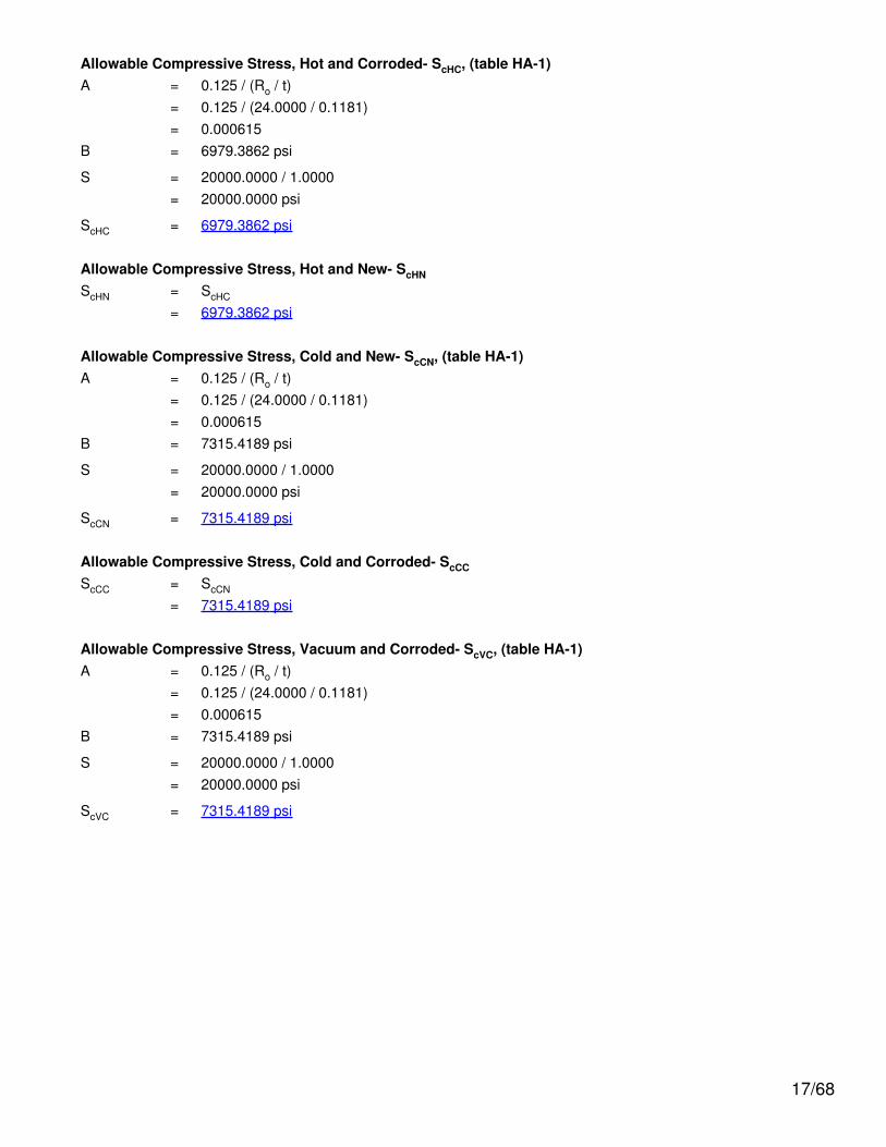
Allowable Compressive Stress, Hot and Corroded- ScHC, (table HA-1)A = 0.125 / (Ro / t)
= 0.125 / (24.0000 / 0.1181)= 0.000615
B = 6979.3862 psi
S = 20000.0000 / 1.0000= 20000.0000 psi
ScHC = 6979.3862 psi
Allowable Compressive Stress, Hot and New- ScHN
ScHN = ScHC
= 6979.3862 psi
Allowable Compressive Stress, Cold and New- ScCN, (table HA-1)A = 0.125 / (Ro / t)
= 0.125 / (24.0000 / 0.1181)= 0.000615
B = 7315.4189 psi
S = 20000.0000 / 1.0000= 20000.0000 psi
ScCN = 7315.4189 psi
Allowable Compressive Stress, Cold and Corroded- ScCC
ScCC = ScCN
= 7315.4189 psi
Allowable Compressive Stress, Vacuum and Corroded- ScVC, (table HA-1)A = 0.125 / (Ro / t)
= 0.125 / (24.0000 / 0.1181)= 0.000615
B = 7315.4189 psi
S = 20000.0000 / 1.0000= 20000.0000 psi
ScVC = 7315.4189 psi
17/68
Straight Flange on Ellipsoidal Head #1
ASME Section VIII Division 1, 2007 Edition
Component: Straight FlangeMaterial specification: SA-240 304 (II-D p. 90, ln. 4)Rated MDMT per UHA-51(d)(1)(a) = -320 °F
Internal design pressure: P = 50 psi @ 158°F
Static liquid head:
Pth =1.9447 psi (SG=1.0000, Hs=53.8750", Horizontal test head)
Corrosion allowance: Inner C = 0.0000" Outer C = 0.0000"
Design MDMT = -20.00°F No impact test performedRated MDMT = -320.00°F Material is not normalized
Material is not produced to Fine Grain PracticePWHT is not performed
Radiography: Longitudinal joint - Full UW-11(a) Type 1Circumferential joint - Full UW-11(a) Type 1
Estimated weight: New = 10.9043 lb corr = 10.9043 lbCapacity: New = 15.5044 gal corr = 15.5044 galOD = 48.0000"Length Lc = 2.0000"t = 0.1250"
Design thickness, (at 158.00°F) Appendix 1-1
t = P*Ro/(S*E + 0.40*P) + Corrosion= 50.00*24.0000/(20000*1.00 + 0.40*50.00) + 0.0000= 0.0600"
Maximum allowable working pressure, (at 158.00°F) Appendix 1-1
P = S*E*t/(Ro - 0.40*t) - Ps= 20000*1.00*0.1250 / (24.0000 - 0.40*0.1250) - 0.0000= 104.3841 psi
Maximum allowable pressure, (at 70.00°F) Appendix 1-1
P = S*E*t/(Ro - 0.40*t)= 20000*1.00*0.1250 / (24.0000 - 0.40*0.1250)= 104.3841 psi
% Forming Strain - UHA-44(a)(2)(a)
= (50 * t / Rf) * (1 - Rf / Ro)= (50 * 0.1250 / 23.9375) * (1 - 23.9375 / ∞)= 0.2611 %
18/68

Allowable Compressive Stress, Hot and Corroded- ScHC, (table HA-1)A = 0.125 / (Ro / t)
= 0.125 / (24.0000 / 0.1250)= 0.000651
B = 7137.3750 psi
S = 20000.0000 / 1.0000= 20000.0000 psi
ScHC = 7137.3750 psi
Allowable Compressive Stress, Hot and New- ScHN
ScHN = ScHC
= 7137.3750 psi
Allowable Compressive Stress, Cold and New- ScCN, (table HA-1)A = 0.125 / (Ro / t)
= 0.125 / (24.0000 / 0.1250)= 0.000651
B = 7490.2925 psi
S = 20000.0000 / 1.0000= 20000.0000 psi
ScCN = 7490.2925 psi
Allowable Compressive Stress, Cold and Corroded- ScCC
ScCC = ScCN
= 7490.2925 psi
Allowable Compressive Stress, Vacuum and Corroded- ScVC, (table HA-1)A = 0.125 / (Ro / t)
= 0.125 / (24.0000 / 0.1250)= 0.000651
B = 7490.2925 psi
S = 20000.0000 / 1.0000= 20000.0000 psi
ScVC = 7490.2925 psi
19/68
Ellipsoidal Head #1
ASME Section VIII, Division 1, 2007 Edition
Component: Ellipsoidal HeadMaterial Specification: SA-240 304 (II-D p.90, ln. 4)Material Rated MDMT per UHA-51(d)(1)(a) = -320 °F
Internal design pressure: P = 50 psi @ 158 °F
Static liquid head:
Ps= 0 psi (SG=1, Hs=0" Operating head)Pth= 1.9447 psi (SG=1, Hs=53.875" Horizontal test head)
Corrosion allowance: Inner C = 0" Outer C = 0"
Design MDMT = -20°F No impact test performedRated MDMT = -320°F Material is not normalized
Material is not produced to fine grain practicePWHT is not performedDo not Optimize MDMT / Find MAWP
Radiography: Category A joints - Full UW-11(a) Type 1 Head to shell seam - Full UW-11(a) Type 1
Estimated weight*: new = 106.6 lb corr = 106.6 lbCapacity*: new = 77.2 US gal corr = 77.2 US gal* includes straight flange
Outer diameter = 48"Minimum head thickness = 0.125"Head ratio D/2h = 2 (new)Head ratio D/2h = 2 (corroded)Straight flange length Lsf = 2"Nominal straight flange thickness tsf = 0.125"Results Summary
The governing condition is UG-16.Minimum thickness per UG-16 = 0.0625" + 0" = 0.0625"Design thickness due to internal pressure (t) = 0.0599"Maximum allowable working pressure (MAWP) = 104.66 psiMaximum allowable pressure (MAP) = 104.66 psi
K (Corroded)
K=(1/6)*[2 + (D / (2*h))2]=(1/6)*[2 + (47.75 / (2*11.9375))2]=1
K (New)
K=(1/6)*[2 + (D / (2*h))2]=(1/6)*[2 + (47.75 / (2*11.9375))2]=1
20/68
Design thickness for internal pressure, (Corroded at 158 °F) Appendix 1-4(c)
t = P*Do*K / (2*S*E + 2*P*(K - 0.1)) + Corrosion= 50*48*1 / (2*20,000*1 + 2*50*(1 - 0.1)) + 0= 0.0599"
The head internal pressure design thickness is 0.0599".
Maximum allowable working pressure, (Corroded at 158 °F) Appendix 1-4(c)
P = 2*S*E*t / (K*Do - 2*t*(K - 0.1)) - Ps= 2*20,000*1*0.125 / (1*48 - 2*0.125*(1 - 0.1)) - 0= 104.66 psi
The maximum allowable working pressure (MAWP) is 104.66 psi.
Maximum allowable pressure, (New at 70 °F) Appendix 1-4(c)
P = 2*S*E*t / (K*Do - 2*t*(K - 0.1)) - Ps= 2*20,000*1*0.125 / (1*48 - 2*0.125*(1 - 0.1)) - 0= 104.66 psi
The maximum allowable pressure (MAP) is 104.66 psi.
% Forming strain - UHA-44(a)(2)(b)
= (75*t / Rf)*(1 - Rf / Ro)= (75*0.125 / 8.18)*(1 - 8.18 / ∞)= 1.1461%
21/68
N2 (N2)
ASME Section VIII Division 1, 2007 Edition
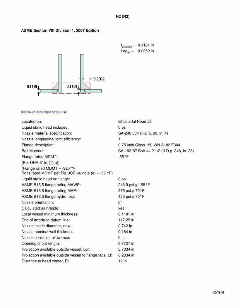
tw(lower) = 0.1181 inLeg41 = 0.2362 in
Note: round inside edges per UG-76(c)
Located on: Ellipsoidal Head #2Liquid static head included: 0 psiNozzle material specification: SA-240 304 (II-D p. 90, ln. 4)Nozzle longitudinal joint efficiency: 1Flange description: 0.75 inch Class 150 WN A182 F304Bolt Material: SA-193 B7 Bolt <= 2 1/2 (II-D p. 348, ln. 33)Flange rated MDMT: -55°F(Per UHA-51(d)(1)(a))(Flange rated MDMT = -320 °FBolts rated MDMT per Fig UCS-66 note (e) = -55 °F)Liquid static head on flange: 0 psiASME B16.5 flange rating MAWP: 248.9 psi @ 158°FASME B16.5 flange rating MAP: 275 psi @ 70°FASME B16.5 flange hydro test: 425 psi @ 70°FNozzle orientation: 0°Calculated as hillside: yesLocal vessel minimum thickness: 0.1181 inEnd of nozzle to datum line: 117.25 inNozzle inside diameter, new: 0.742 inNozzle nominal wall thickness: 0.154 inNozzle corrosion allowance: 0 inOpening chord length: 0.7727 inProjection available outside vessel, Lpr: 5.7334 inProjection available outside vessel to flange face, Lf: 6.2334 inDistance to head center, R: 12 in
22/68

Reinforcement Calculations for Internal Pressure
The vessel wall thickness governs the MAWP of this nozzle.
UG-37 Area Calculation Summary(in2)
For P = 109.59 psi @ 158 °F
UG-45 NozzleWall
ThicknessSummary (in)The nozzle passes
UG-45
Arequired
Aavailable A1 A2 A3 A5
Awelds treq tmin
This nozzle is exempt from areacalculations per UG-36(c)(3)(a) 0.0989 0.154
Weld Failure Path Analysis Summary
The nozzle is exempt from weld strengthcalculations per UW-15(b)(2)
UW-16 Weld Sizing Summary
Weld description Required weldthroat size (in)
Actual weldthroat size (in) Status
Nozzle to shell fillet (Leg41) 0.0827 0.1654 weld size is adequate
Calculations for internal pressure 109.59 psi @ 158 °F
Nozzle rated MDMT per UHA-51(d)(1)(a) = -320 °F.
Limits of reinforcement per UG-40
Parallel to the vessel wall: d = 0.7727 inNormal to the vessel wall outside: 2.5*(t - C) = 0.2953 in
Nozzle required thickness per UG-27(c)(1)
trn = P*Rn/(Sn*E - 0.6*P)= 109.5913*0.371/(20,000*1 - 0.6*109.5913)= 0.002 in
Required thickness tr from UG-37(a)(c)
tr = P*K1*Do/(2*S*E + 0.8*P)= 109.5913*0.9*48/(2*20,000*1 + 0.8*109.5913)= 0.1181 in
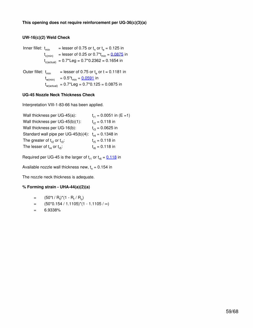
This opening does not require reinforcement per UG-36(c)(3)(a)
UW-16(c) Weld Check
23/68
Fillet weld: tmin = lesser of 0.75 or tn or t = 0.1181 intc(min) = lesser of 0.25 or 0.7*tmin = 0.0827 intc(actual) = 0.7*Leg = 0.7*0.2362 = 0.1654 in
The fillet weld size is satisfactory.
Weld strength calculations are not required for this detail which conforms to Fig. UW-16.1, sketch (c-e).
UG-45 Nozzle Neck Thickness Check
Interpretation VIII-1-83-66 has been applied.
Wall thickness per UG-45(a): tr1 = 0.002 in (E =1)Wall thickness per UG-45(b)(1): tr2 = 0.1309 inWall thickness per UG-16(b): tr3 = 0.0625 inStandard wall pipe per UG-45(b)(4): tr4 = 0.0989 inThe greater of tr2 or tr3: tr5 = 0.1309 inThe lesser of tr4 or tr5: tr6 = 0.0989 in
Required per UG-45 is the larger of tr1 or tr6 = 0.0989 in
Available nozzle wall thickness new, tn = 0.154 in
The nozzle neck thickness is adequate.
% Forming strain - UHA-44(a)(2)(a)
= (50*t / Rf)*(1 - Rf / Ro)= (50*0.154 / 0.448)*(1 - 0.448 / ∞)= 17.1875%
24/68

Reinforcement Calculations for MAP
The vessel wall thickness governs the MAP of this nozzle.
UG-37 Area Calculation Summary(in2)
For P = 109.59 psi @ 70 °F
UG-45 NozzleWall
ThicknessSummary (in)The nozzle passes
UG-45
Arequired
Aavailable A1 A2 A3 A5
Awelds treq tmin
This nozzle is exempt from areacalculations per UG-36(c)(3)(a) 0.0989 0.154
Weld Failure Path Analysis Summary
The nozzle is exempt from weld strengthcalculations per UW-15(b)(2)
UW-16 Weld Sizing Summary
Weld description Required weldthroat size (in)
Actual weldthroat size (in) Status
Nozzle to shell fillet (Leg41) 0.0827 0.1654 weld size is adequate
Calculations for internal pressure 109.59 psi @ 70 °F
Nozzle rated MDMT per UHA-51(d)(1)(a) = -320 °F.
Limits of reinforcement per UG-40
Parallel to the vessel wall: d = 0.7727 inNormal to the vessel wall outside: 2.5*(t - C) = 0.2953 in
Nozzle required thickness per UG-27(c)(1)
trn = P*Rn/(Sn*E - 0.6*P)= 109.5913*0.371/(20,000*1 - 0.6*109.5913)= 0.002 in
Required thickness tr from UG-37(a)(c)
tr = P*K1*Do/(2*S*E + 0.8*P)= 109.5913*0.9*48/(2*20,000*1 + 0.8*109.5913)= 0.1181 in
This opening does not require reinforcement per UG-36(c)(3)(a)
25/68

UW-16(c) Weld Check
Fillet weld: tmin = lesser of 0.75 or tn or t = 0.1181 intc(min) = lesser of 0.25 or 0.7*tmin = 0.0827 intc(actual) = 0.7*Leg = 0.7*0.2362 = 0.1654 in
The fillet weld size is satisfactory.
Weld strength calculations are not required for this detail which conforms to Fig. UW-16.1, sketch (c-e).
UG-45 Nozzle Neck Thickness Check
Interpretation VIII-1-83-66 has been applied.
Wall thickness per UG-45(a): tr1 = 0.002 in (E =1)Wall thickness per UG-45(b)(1): tr2 = 0.1309 inWall thickness per UG-16(b): tr3 = 0.0625 inStandard wall pipe per UG-45(b)(4): tr4 = 0.0989 inThe greater of tr2 or tr3: tr5 = 0.1309 inThe lesser of tr4 or tr5: tr6 = 0.0989 in
Required per UG-45 is the larger of tr1 or tr6 = 0.0989 in
Available nozzle wall thickness new, tn = 0.154 in
The nozzle neck thickness is adequate.
26/68

N3 (N3)
ASME Section VIII Division 1, 2007 Edition
tw(lower) = 0.1181 inLeg41 = 0.2362 in
Note: round inside edges per UG-76(c)
Located on: Ellipsoidal Head #2Liquid static head included: 0 psiNozzle material specification: SA-240 304 (II-D p. 90, ln. 4)Nozzle longitudinal joint efficiency: 1Flange description: 0.75 inch Class 150 WN A182 F304Bolt Material: SA-193 B7 Bolt <= 2 1/2 (II-D p. 348, ln. 33)Flange rated MDMT: -55°F(Per UHA-51(d)(1)(a))(Flange rated MDMT = -320 °FBolts rated MDMT per Fig UCS-66 note (e) = -55 °F)Liquid static head on flange: 0 psiASME B16.5 flange rating MAWP: 248.9 psi @ 158°FASME B16.5 flange rating MAP: 275 psi @ 70°FASME B16.5 flange hydro test: 425 psi @ 70°FNozzle orientation: 180°Calculated as hillside: yesLocal vessel minimum thickness: 0.1181 inEnd of nozzle to datum line: 117.25 inNozzle inside diameter, new: 0.742 inNozzle nominal wall thickness: 0.154 inNozzle corrosion allowance: 0 inOpening chord length: 0.7727 inProjection available outside vessel, Lpr: 5.7334 inProjection available outside vessel to flange face, Lf: 6.2334 inDistance to head center, R: 12 in
27/68

Reinforcement Calculations for Internal Pressure
The vessel wall thickness governs the MAWP of this nozzle.
UG-37 Area Calculation Summary(in2)
For P = 109.59 psi @ 158 °F
UG-45 NozzleWall
ThicknessSummary (in)The nozzle passes
UG-45
Arequired
Aavailable A1 A2 A3 A5
Awelds treq tmin
This nozzle is exempt from areacalculations per UG-36(c)(3)(a) 0.0989 0.154
Weld Failure Path Analysis Summary
The nozzle is exempt from weld strengthcalculations per UW-15(b)(2)
UW-16 Weld Sizing Summary
Weld description Required weldthroat size (in)
Actual weldthroat size (in) Status
Nozzle to shell fillet (Leg41) 0.0827 0.1654 weld size is adequate
Calculations for internal pressure 109.59 psi @ 158 °F
Nozzle rated MDMT per UHA-51(d)(1)(a) = -320 °F.
Limits of reinforcement per UG-40
Parallel to the vessel wall: d = 0.7727 inNormal to the vessel wall outside: 2.5*(t - C) = 0.2953 in
Nozzle required thickness per UG-27(c)(1)
trn = P*Rn/(Sn*E - 0.6*P)= 109.5913*0.371/(20,000*1 - 0.6*109.5913)= 0.002 in
Required thickness tr from UG-37(a)(c)
tr = P*K1*Do/(2*S*E + 0.8*P)= 109.5913*0.9*48/(2*20,000*1 + 0.8*109.5913)= 0.1181 in
This opening does not require reinforcement per UG-36(c)(3)(a)
UW-16(c) Weld Check
28/68

Fillet weld: tmin = lesser of 0.75 or tn or t = 0.1181 intc(min) = lesser of 0.25 or 0.7*tmin = 0.0827 intc(actual) = 0.7*Leg = 0.7*0.2362 = 0.1654 in
The fillet weld size is satisfactory.
Weld strength calculations are not required for this detail which conforms to Fig. UW-16.1, sketch (c-e).
UG-45 Nozzle Neck Thickness Check
Interpretation VIII-1-83-66 has been applied.
Wall thickness per UG-45(a): tr1 = 0.002 in (E =1)Wall thickness per UG-45(b)(1): tr2 = 0.1309 inWall thickness per UG-16(b): tr3 = 0.0625 inStandard wall pipe per UG-45(b)(4): tr4 = 0.0989 inThe greater of tr2 or tr3: tr5 = 0.1309 inThe lesser of tr4 or tr5: tr6 = 0.0989 in
Required per UG-45 is the larger of tr1 or tr6 = 0.0989 in
Available nozzle wall thickness new, tn = 0.154 in
The nozzle neck thickness is adequate.
% Forming strain - UHA-44(a)(2)(a)
= (50*t / Rf)*(1 - Rf / Ro)= (50*0.154 / 0.448)*(1 - 0.448 / ∞)= 17.1875%
29/68

Reinforcement Calculations for MAP
The vessel wall thickness governs the MAP of this nozzle.
UG-37 Area Calculation Summary(in2)
For P = 109.59 psi @ 70 °F
UG-45 NozzleWall
ThicknessSummary (in)The nozzle passes
UG-45
Arequired
Aavailable A1 A2 A3 A5
Awelds treq tmin
This nozzle is exempt from areacalculations per UG-36(c)(3)(a) 0.0989 0.154
Weld Failure Path Analysis Summary
The nozzle is exempt from weld strengthcalculations per UW-15(b)(2)
UW-16 Weld Sizing Summary
Weld description Required weldthroat size (in)
Actual weldthroat size (in) Status
Nozzle to shell fillet (Leg41) 0.0827 0.1654 weld size is adequate
Calculations for internal pressure 109.59 psi @ 70 °F
Nozzle rated MDMT per UHA-51(d)(1)(a) = -320 °F.
Limits of reinforcement per UG-40
Parallel to the vessel wall: d = 0.7727 inNormal to the vessel wall outside: 2.5*(t - C) = 0.2953 in
Nozzle required thickness per UG-27(c)(1)
trn = P*Rn/(Sn*E - 0.6*P)= 109.5913*0.371/(20,000*1 - 0.6*109.5913)= 0.002 in
Required thickness tr from UG-37(a)(c)
tr = P*K1*Do/(2*S*E + 0.8*P)= 109.5913*0.9*48/(2*20,000*1 + 0.8*109.5913)= 0.1181 in
This opening does not require reinforcement per UG-36(c)(3)(a)
30/68

UW-16(c) Weld Check
Fillet weld: tmin = lesser of 0.75 or tn or t = 0.1181 intc(min) = lesser of 0.25 or 0.7*tmin = 0.0827 intc(actual) = 0.7*Leg = 0.7*0.2362 = 0.1654 in
The fillet weld size is satisfactory.
Weld strength calculations are not required for this detail which conforms to Fig. UW-16.1, sketch (c-e).
UG-45 Nozzle Neck Thickness Check
Interpretation VIII-1-83-66 has been applied.
Wall thickness per UG-45(a): tr1 = 0.002 in (E =1)Wall thickness per UG-45(b)(1): tr2 = 0.1309 inWall thickness per UG-16(b): tr3 = 0.0625 inStandard wall pipe per UG-45(b)(4): tr4 = 0.0989 inThe greater of tr2 or tr3: tr5 = 0.1309 inThe lesser of tr4 or tr5: tr6 = 0.0989 in
Required per UG-45 is the larger of tr1 or tr6 = 0.0989 in
Available nozzle wall thickness new, tn = 0.154 in
The nozzle neck thickness is adequate.
31/68
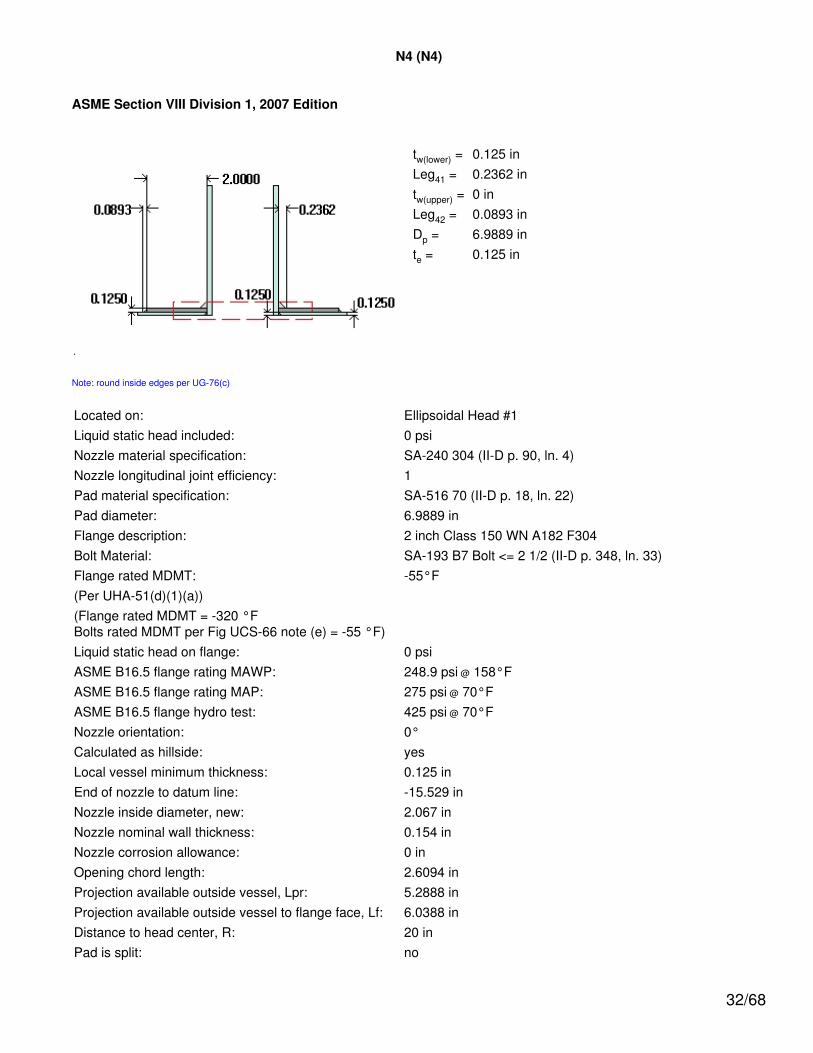
N4 (N4)
ASME Section VIII Division 1, 2007 Edition
tw(lower) = 0.125 inLeg41 = 0.2362 intw(upper) = 0 inLeg42 = 0.0893 inDp = 6.9889 inte = 0.125 in
Note: round inside edges per UG-76(c)
Located on: Ellipsoidal Head #1Liquid static head included: 0 psiNozzle material specification: SA-240 304 (II-D p. 90, ln. 4)Nozzle longitudinal joint efficiency: 1Pad material specification: SA-516 70 (II-D p. 18, ln. 22)Pad diameter: 6.9889 inFlange description: 2 inch Class 150 WN A182 F304Bolt Material: SA-193 B7 Bolt <= 2 1/2 (II-D p. 348, ln. 33)Flange rated MDMT: -55°F(Per UHA-51(d)(1)(a))(Flange rated MDMT = -320 °FBolts rated MDMT per Fig UCS-66 note (e) = -55 °F)Liquid static head on flange: 0 psiASME B16.5 flange rating MAWP: 248.9 psi @ 158°FASME B16.5 flange rating MAP: 275 psi @ 70°FASME B16.5 flange hydro test: 425 psi @ 70°FNozzle orientation: 0°Calculated as hillside: yesLocal vessel minimum thickness: 0.125 inEnd of nozzle to datum line: -15.529 inNozzle inside diameter, new: 2.067 inNozzle nominal wall thickness: 0.154 inNozzle corrosion allowance: 0 inOpening chord length: 2.6094 inProjection available outside vessel, Lpr: 5.2888 inProjection available outside vessel to flange face, Lf: 6.0388 inDistance to head center, R: 20 inPad is split: no
32/68

Reinforcement Calculations for Internal Pressure
The vessel wall thickness governs the MAWP of this nozzle.
UG-37 Area Calculation Summary(in2)
For P = 104.66 psi @ 158 °F
UG-45Nozzle WallThicknessSummary
(in)The nozzle
passes UG-45
Arequired
Aavailable A1 A2 A3 A5
Awelds treq tmin
This nozzle is exempt from areacalculations per UG-36(c)(3)(a) 0.125 0.154
Weld Failure Path Analysis Summary
The nozzle is exempt from weld strengthcalculations per UW-15(b)(2)
UW-16 Weld Sizing Summary
Weld description Required weldthroat size (in)
Actual weldthroat size (in) Status
Nozzle to pad fillet (Leg41) 0.0875 0.1654 weld size is adequate
Pad to shell fillet (Leg42) 0.0625 0.0625 weld size is adequate
Calculations for internal pressure 104.66 psi @ 158 °F
Nozzle rated MDMT per UHA-51(d)(1)(a) = -320 °F.Pad impact test exemption temperature from Fig UCS-66 Curve B = -20 °FFig UCS-66.1 MDMT reduction = 5.8 °F, (coincident ratio = 0.94248).
Pad UCS-66 governing thickness: 0.125 inPad rated MDMT: -25.8 °F
Limits of reinforcement per UG-40
Parallel to the vessel wall: d = 2.6094 inNormal to the vessel wall outside: 2.5*(t - C) = 0.3125 in
Nozzle required thickness per UG-27(c)(1)
trn = P*Rn/(Sn*E - 0.6*P)= 104.657*1.0335/(20,000*1 - 0.6*104.657)= 0.0054 in
Required thickness tr from UG-37(a)
tr = P*Do*K / (2*S*E + 2*P*(K - 0.1))
33/68
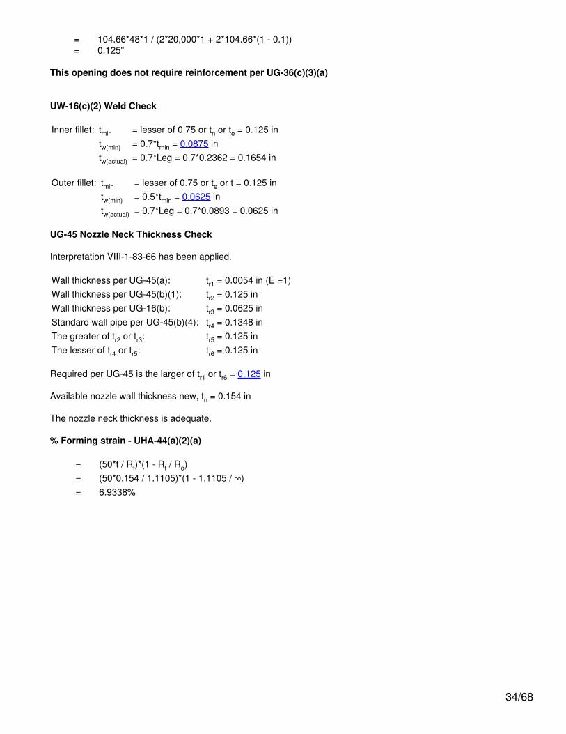
= 104.66*48*1 / (2*20,000*1 + 2*104.66*(1 - 0.1))= 0.125"
This opening does not require reinforcement per UG-36(c)(3)(a)
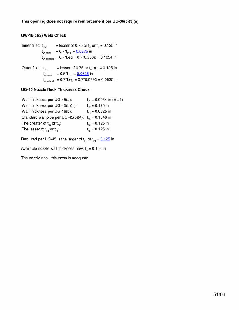
UW-16(c)(2) Weld Check
Inner fillet: tmin = lesser of 0.75 or tn or te = 0.125 intw(min) = 0.7*tmin = 0.0875 intw(actual) = 0.7*Leg = 0.7*0.2362 = 0.1654 in
Outer fillet: tmin = lesser of 0.75 or te or t = 0.125 intw(min) = 0.5*tmin = 0.0625 intw(actual) = 0.7*Leg = 0.7*0.0893 = 0.0625 in
UG-45 Nozzle Neck Thickness Check
Interpretation VIII-1-83-66 has been applied.
Wall thickness per UG-45(a): tr1 = 0.0054 in (E =1)Wall thickness per UG-45(b)(1): tr2 = 0.125 inWall thickness per UG-16(b): tr3 = 0.0625 inStandard wall pipe per UG-45(b)(4): tr4 = 0.1348 inThe greater of tr2 or tr3: tr5 = 0.125 inThe lesser of tr4 or tr5: tr6 = 0.125 in
Required per UG-45 is the larger of tr1 or tr6 = 0.125 in
Available nozzle wall thickness new, tn = 0.154 in
The nozzle neck thickness is adequate.
% Forming strain - UHA-44(a)(2)(a)
= (50*t / Rf)*(1 - Rf / Ro)= (50*0.154 / 1.1105)*(1 - 1.1105 / ∞)= 6.9338%
34/68
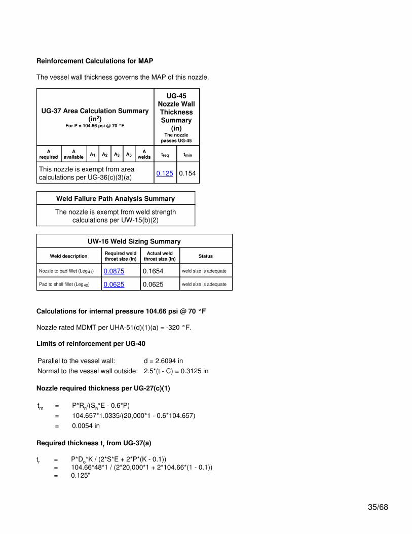
Reinforcement Calculations for MAP
The vessel wall thickness governs the MAP of this nozzle.
UG-37 Area Calculation Summary(in2)
For P = 104.66 psi @ 70 °F
UG-45Nozzle WallThicknessSummary
(in)The nozzle
passes UG-45
Arequired
Aavailable A1 A2 A3 A5
Awelds treq tmin
This nozzle is exempt from areacalculations per UG-36(c)(3)(a) 0.125 0.154
Weld Failure Path Analysis Summary
The nozzle is exempt from weld strengthcalculations per UW-15(b)(2)
UW-16 Weld Sizing Summary
Weld description Required weldthroat size (in)
Actual weldthroat size (in) Status
Nozzle to pad fillet (Leg41) 0.0875 0.1654 weld size is adequate
Pad to shell fillet (Leg42) 0.0625 0.0625 weld size is adequate
Calculations for internal pressure 104.66 psi @ 70 °F
Nozzle rated MDMT per UHA-51(d)(1)(a) = -320 °F.
Limits of reinforcement per UG-40
Parallel to the vessel wall: d = 2.6094 inNormal to the vessel wall outside: 2.5*(t - C) = 0.3125 in
Nozzle required thickness per UG-27(c)(1)
trn = P*Rn/(Sn*E - 0.6*P)= 104.657*1.0335/(20,000*1 - 0.6*104.657)= 0.0054 in
Required thickness tr from UG-37(a)
tr = P*Do*K / (2*S*E + 2*P*(K - 0.1))= 104.66*48*1 / (2*20,000*1 + 2*104.66*(1 - 0.1))= 0.125"
35/68
This opening does not require reinforcement per UG-36(c)(3)(a)
UW-16(c)(2) Weld Check
Inner fillet: tmin = lesser of 0.75 or tn or te = 0.125 intw(min) = 0.7*tmin = 0.0875 intw(actual) = 0.7*Leg = 0.7*0.2362 = 0.1654 in
Outer fillet: tmin = lesser of 0.75 or te or t = 0.125 intw(min) = 0.5*tmin = 0.0625 intw(actual) = 0.7*Leg = 0.7*0.0893 = 0.0625 in
UG-45 Nozzle Neck Thickness Check
Interpretation VIII-1-83-66 has been applied.
Wall thickness per UG-45(a): tr1 = 0.0054 in (E =1)Wall thickness per UG-45(b)(1): tr2 = 0.125 inWall thickness per UG-16(b): tr3 = 0.0625 inStandard wall pipe per UG-45(b)(4): tr4 = 0.1348 inThe greater of tr2 or tr3: tr5 = 0.125 inThe lesser of tr4 or tr5: tr6 = 0.125 in
Required per UG-45 is the larger of tr1 or tr6 = 0.125 in
Available nozzle wall thickness new, tn = 0.154 in
The nozzle neck thickness is adequate.
36/68
N5 (N5)
ASME Section VIII Division 1, 2007 Edition
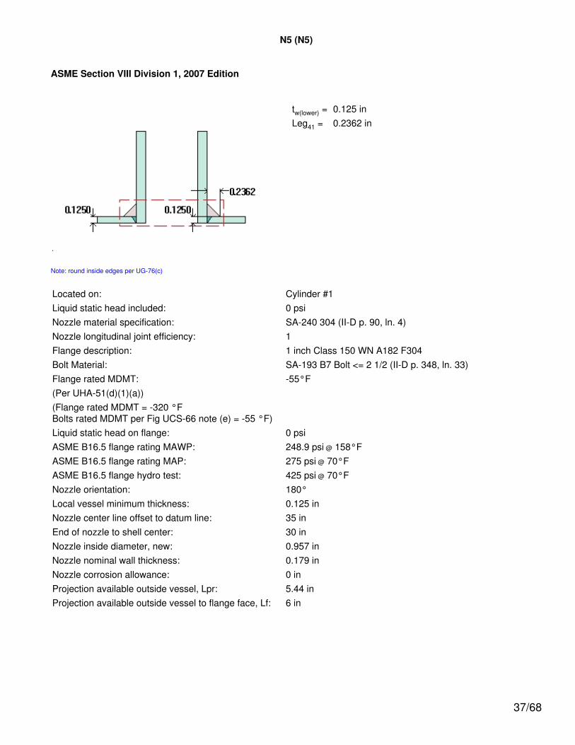
tw(lower) = 0.125 inLeg41 = 0.2362 in
Note: round inside edges per UG-76(c)
Located on: Cylinder #1Liquid static head included: 0 psiNozzle material specification: SA-240 304 (II-D p. 90, ln. 4)Nozzle longitudinal joint efficiency: 1Flange description: 1 inch Class 150 WN A182 F304Bolt Material: SA-193 B7 Bolt <= 2 1/2 (II-D p. 348, ln. 33)Flange rated MDMT: -55°F(Per UHA-51(d)(1)(a))(Flange rated MDMT = -320 °FBolts rated MDMT per Fig UCS-66 note (e) = -55 °F)Liquid static head on flange: 0 psiASME B16.5 flange rating MAWP: 248.9 psi @ 158°FASME B16.5 flange rating MAP: 275 psi @ 70°FASME B16.5 flange hydro test: 425 psi @ 70°FNozzle orientation: 180°Local vessel minimum thickness: 0.125 inNozzle center line offset to datum line: 35 inEnd of nozzle to shell center: 30 inNozzle inside diameter, new: 0.957 inNozzle nominal wall thickness: 0.179 inNozzle corrosion allowance: 0 inProjection available outside vessel, Lpr: 5.44 inProjection available outside vessel to flange face, Lf: 6 in
37/68
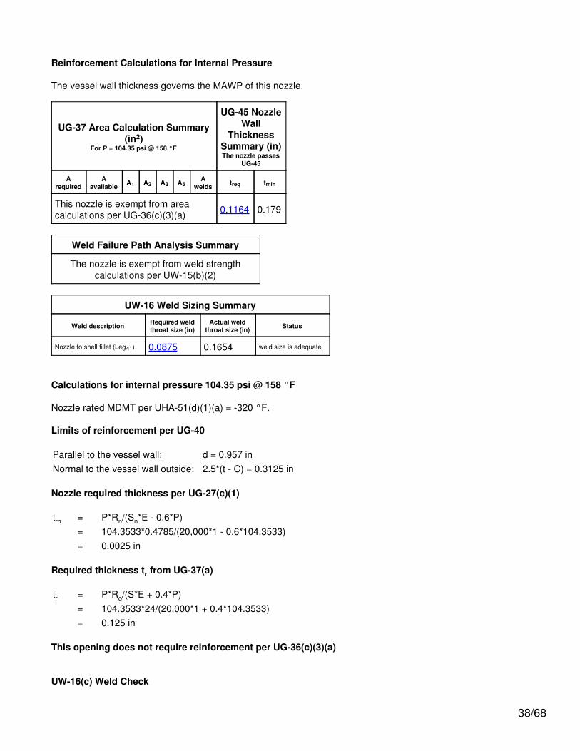
Reinforcement Calculations for Internal Pressure
The vessel wall thickness governs the MAWP of this nozzle.
UG-37 Area Calculation Summary(in2)
For P = 104.35 psi @ 158 °F
UG-45 NozzleWall
ThicknessSummary (in)The nozzle passes
UG-45
Arequired
Aavailable A1 A2 A3 A5
Awelds treq tmin
This nozzle is exempt from areacalculations per UG-36(c)(3)(a) 0.1164 0.179
Weld Failure Path Analysis Summary
The nozzle is exempt from weld strengthcalculations per UW-15(b)(2)
UW-16 Weld Sizing Summary
Weld description Required weldthroat size (in)
Actual weldthroat size (in) Status
Nozzle to shell fillet (Leg41) 0.0875 0.1654 weld size is adequate
Calculations for internal pressure 104.35 psi @ 158 °F
Nozzle rated MDMT per UHA-51(d)(1)(a) = -320 °F.
Limits of reinforcement per UG-40
Parallel to the vessel wall: d = 0.957 inNormal to the vessel wall outside: 2.5*(t - C) = 0.3125 in
Nozzle required thickness per UG-27(c)(1)
trn = P*Rn/(Sn*E - 0.6*P)= 104.3533*0.4785/(20,000*1 - 0.6*104.3533)= 0.0025 in
Required thickness tr from UG-37(a)
tr = P*Ro/(S*E + 0.4*P)= 104.3533*24/(20,000*1 + 0.4*104.3533)= 0.125 in
This opening does not require reinforcement per UG-36(c)(3)(a)
UW-16(c) Weld Check
38/68
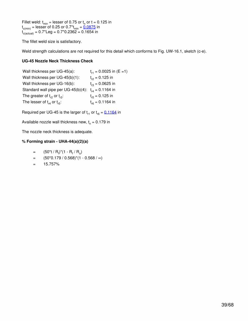
Fillet weld: tmin = lesser of 0.75 or tn or t = 0.125 intc(min) = lesser of 0.25 or 0.7*tmin = 0.0875 intc(actual) = 0.7*Leg = 0.7*0.2362 = 0.1654 in
The fillet weld size is satisfactory.
Weld strength calculations are not required for this detail which conforms to Fig. UW-16.1, sketch (c-e).
UG-45 Nozzle Neck Thickness Check
Wall thickness per UG-45(a): tr1 = 0.0025 in (E =1)Wall thickness per UG-45(b)(1): tr2 = 0.125 inWall thickness per UG-16(b): tr3 = 0.0625 inStandard wall pipe per UG-45(b)(4): tr4 = 0.1164 inThe greater of tr2 or tr3: tr5 = 0.125 inThe lesser of tr4 or tr5: tr6 = 0.1164 in
Required per UG-45 is the larger of tr1 or tr6 = 0.1164 in
Available nozzle wall thickness new, tn = 0.179 in
The nozzle neck thickness is adequate.
% Forming strain - UHA-44(a)(2)(a)
= (50*t / Rf)*(1 - Rf / Ro)= (50*0.179 / 0.568)*(1 - 0.568 / ∞)= 15.757%
39/68
Reinforcement Calculations for MAP
The vessel wall thickness governs the MAP of this nozzle.
UG-37 Area Calculation Summary(in2)
For P = 104.35 psi @ 70 °F
UG-45 NozzleWall
ThicknessSummary (in)The nozzle passes
UG-45
Arequired
Aavailable A1 A2 A3 A5
Awelds treq tmin
This nozzle is exempt from areacalculations per UG-36(c)(3)(a) 0.1164 0.179
Weld Failure Path Analysis Summary
The nozzle is exempt from weld strengthcalculations per UW-15(b)(2)
UW-16 Weld Sizing Summary
Weld description Required weldthroat size (in)
Actual weldthroat size (in) Status
Nozzle to shell fillet (Leg41) 0.0875 0.1654 weld size is adequate
Calculations for internal pressure 104.35 psi @ 70 °F
Nozzle rated MDMT per UHA-51(d)(1)(a) = -320 °F.
Limits of reinforcement per UG-40
Parallel to the vessel wall: d = 0.957 inNormal to the vessel wall outside: 2.5*(t - C) = 0.3125 in
Nozzle required thickness per UG-27(c)(1)
trn = P*Rn/(Sn*E - 0.6*P)= 104.3533*0.4785/(20,000*1 - 0.6*104.3533)= 0.0025 in
Required thickness tr from UG-37(a)
tr = P*Ro/(S*E + 0.4*P)= 104.3533*24/(20,000*1 + 0.4*104.3533)= 0.125 in
This opening does not require reinforcement per UG-36(c)(3)(a)
40/68
UW-16(c) Weld Check
Fillet weld: tmin = lesser of 0.75 or tn or t = 0.125 intc(min) = lesser of 0.25 or 0.7*tmin = 0.0875 intc(actual) = 0.7*Leg = 0.7*0.2362 = 0.1654 in
The fillet weld size is satisfactory.
Weld strength calculations are not required for this detail which conforms to Fig. UW-16.1, sketch (c-e).
UG-45 Nozzle Neck Thickness Check
Wall thickness per UG-45(a): tr1 = 0.0025 in (E =1)Wall thickness per UG-45(b)(1): tr2 = 0.125 inWall thickness per UG-16(b): tr3 = 0.0625 inStandard wall pipe per UG-45(b)(4): tr4 = 0.1164 inThe greater of tr2 or tr3: tr5 = 0.125 inThe lesser of tr4 or tr5: tr6 = 0.1164 in
Required per UG-45 is the larger of tr1 or tr6 = 0.1164 in
Available nozzle wall thickness new, tn = 0.179 in
The nozzle neck thickness is adequate.
41/68
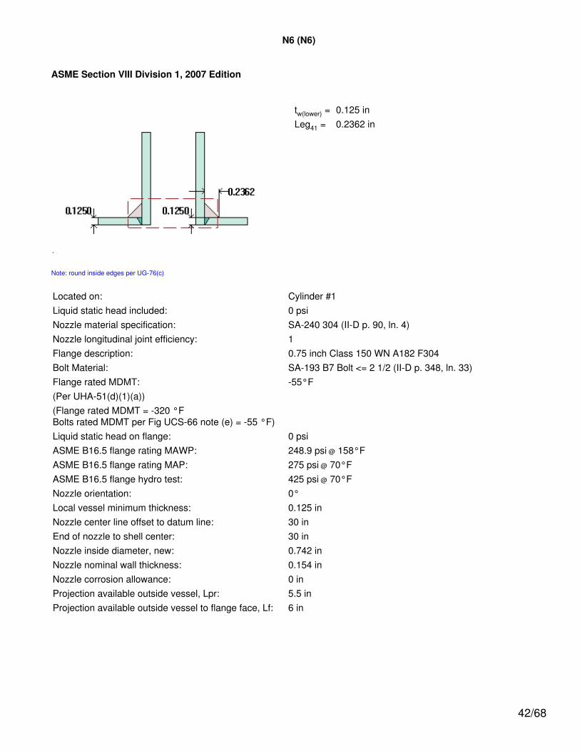
N6 (N6)
ASME Section VIII Division 1, 2007 Edition
tw(lower) = 0.125 inLeg41 = 0.2362 in
Note: round inside edges per UG-76(c)
Located on: Cylinder #1Liquid static head included: 0 psiNozzle material specification: SA-240 304 (II-D p. 90, ln. 4)Nozzle longitudinal joint efficiency: 1Flange description: 0.75 inch Class 150 WN A182 F304Bolt Material: SA-193 B7 Bolt <= 2 1/2 (II-D p. 348, ln. 33)Flange rated MDMT: -55°F(Per UHA-51(d)(1)(a))(Flange rated MDMT = -320 °FBolts rated MDMT per Fig UCS-66 note (e) = -55 °F)Liquid static head on flange: 0 psiASME B16.5 flange rating MAWP: 248.9 psi @ 158°FASME B16.5 flange rating MAP: 275 psi @ 70°FASME B16.5 flange hydro test: 425 psi @ 70°FNozzle orientation: 0°Local vessel minimum thickness: 0.125 inNozzle center line offset to datum line: 30 inEnd of nozzle to shell center: 30 inNozzle inside diameter, new: 0.742 inNozzle nominal wall thickness: 0.154 inNozzle corrosion allowance: 0 inProjection available outside vessel, Lpr: 5.5 inProjection available outside vessel to flange face, Lf: 6 in
42/68

Reinforcement Calculations for Internal Pressure
The vessel wall thickness governs the MAWP of this nozzle.
UG-37 Area Calculation Summary(in2)
For P = 104.35 psi @ 158 °F
UG-45 NozzleWall
ThicknessSummary (in)The nozzle passes
UG-45
Arequired
Aavailable A1 A2 A3 A5
Awelds treq tmin
This nozzle is exempt from areacalculations per UG-36(c)(3)(a) 0.0989 0.154
Weld Failure Path Analysis Summary
The nozzle is exempt from weld strengthcalculations per UW-15(b)(2)
UW-16 Weld Sizing Summary
Weld description Required weldthroat size (in)
Actual weldthroat size (in) Status
Nozzle to shell fillet (Leg41) 0.0875 0.1654 weld size is adequate
Calculations for internal pressure 104.35 psi @ 158 °F
Nozzle rated MDMT per UHA-51(d)(1)(a) = -320 °F.
Limits of reinforcement per UG-40
Parallel to the vessel wall: d = 0.742 inNormal to the vessel wall outside: 2.5*(t - C) = 0.3125 in
Nozzle required thickness per UG-27(c)(1)
trn = P*Rn/(Sn*E - 0.6*P)= 104.3533*0.371/(20,000*1 - 0.6*104.3533)= 0.0019 in
Required thickness tr from UG-37(a)
tr = P*Ro/(S*E + 0.4*P)= 104.3533*24/(20,000*1 + 0.4*104.3533)= 0.125 in
This opening does not require reinforcement per UG-36(c)(3)(a)
UW-16(c) Weld Check
43/68
Fillet weld: tmin = lesser of 0.75 or tn or t = 0.125 intc(min) = lesser of 0.25 or 0.7*tmin = 0.0875 intc(actual) = 0.7*Leg = 0.7*0.2362 = 0.1654 in
The fillet weld size is satisfactory.
Weld strength calculations are not required for this detail which conforms to Fig. UW-16.1, sketch (c-e).
UG-45 Nozzle Neck Thickness Check
Wall thickness per UG-45(a): tr1 = 0.0019 in (E =1)Wall thickness per UG-45(b)(1): tr2 = 0.125 inWall thickness per UG-16(b): tr3 = 0.0625 inStandard wall pipe per UG-45(b)(4): tr4 = 0.0989 inThe greater of tr2 or tr3: tr5 = 0.125 inThe lesser of tr4 or tr5: tr6 = 0.0989 in
Required per UG-45 is the larger of tr1 or tr6 = 0.0989 in
Available nozzle wall thickness new, tn = 0.154 in
The nozzle neck thickness is adequate.
% Forming strain - UHA-44(a)(2)(a)
= (50*t / Rf)*(1 - Rf / Ro)= (50*0.154 / 0.448)*(1 - 0.448 / ∞)= 17.1875%
44/68

Reinforcement Calculations for MAP
The vessel wall thickness governs the MAP of this nozzle.
UG-37 Area Calculation Summary(in2)
For P = 104.35 psi @ 70 °F
UG-45 NozzleWall
ThicknessSummary (in)The nozzle passes
UG-45
Arequired
Aavailable A1 A2 A3 A5
Awelds treq tmin
This nozzle is exempt from areacalculations per UG-36(c)(3)(a) 0.0989 0.154
Weld Failure Path Analysis Summary
The nozzle is exempt from weld strengthcalculations per UW-15(b)(2)
UW-16 Weld Sizing Summary
Weld description Required weldthroat size (in)
Actual weldthroat size (in) Status
Nozzle to shell fillet (Leg41) 0.0875 0.1654 weld size is adequate
Calculations for internal pressure 104.35 psi @ 70 °F
Nozzle rated MDMT per UHA-51(d)(1)(a) = -320 °F.
Limits of reinforcement per UG-40
Parallel to the vessel wall: d = 0.742 inNormal to the vessel wall outside: 2.5*(t - C) = 0.3125 in
Nozzle required thickness per UG-27(c)(1)
trn = P*Rn/(Sn*E - 0.6*P)= 104.3533*0.371/(20,000*1 - 0.6*104.3533)= 0.0019 in
Required thickness tr from UG-37(a)
tr = P*Ro/(S*E + 0.4*P)= 104.3533*24/(20,000*1 + 0.4*104.3533)= 0.125 in
This opening does not require reinforcement per UG-36(c)(3)(a)
45/68
UW-16(c) Weld Check
Fillet weld: tmin = lesser of 0.75 or tn or t = 0.125 intc(min) = lesser of 0.25 or 0.7*tmin = 0.0875 intc(actual) = 0.7*Leg = 0.7*0.2362 = 0.1654 in
The fillet weld size is satisfactory.
Weld strength calculations are not required for this detail which conforms to Fig. UW-16.1, sketch (c-e).
UG-45 Nozzle Neck Thickness Check
Wall thickness per UG-45(a): tr1 = 0.0019 in (E =1)Wall thickness per UG-45(b)(1): tr2 = 0.125 inWall thickness per UG-16(b): tr3 = 0.0625 inStandard wall pipe per UG-45(b)(4): tr4 = 0.0989 inThe greater of tr2 or tr3: tr5 = 0.125 inThe lesser of tr4 or tr5: tr6 = 0.0989 in
Required per UG-45 is the larger of tr1 or tr6 = 0.0989 in
Available nozzle wall thickness new, tn = 0.154 in
The nozzle neck thickness is adequate.
46/68
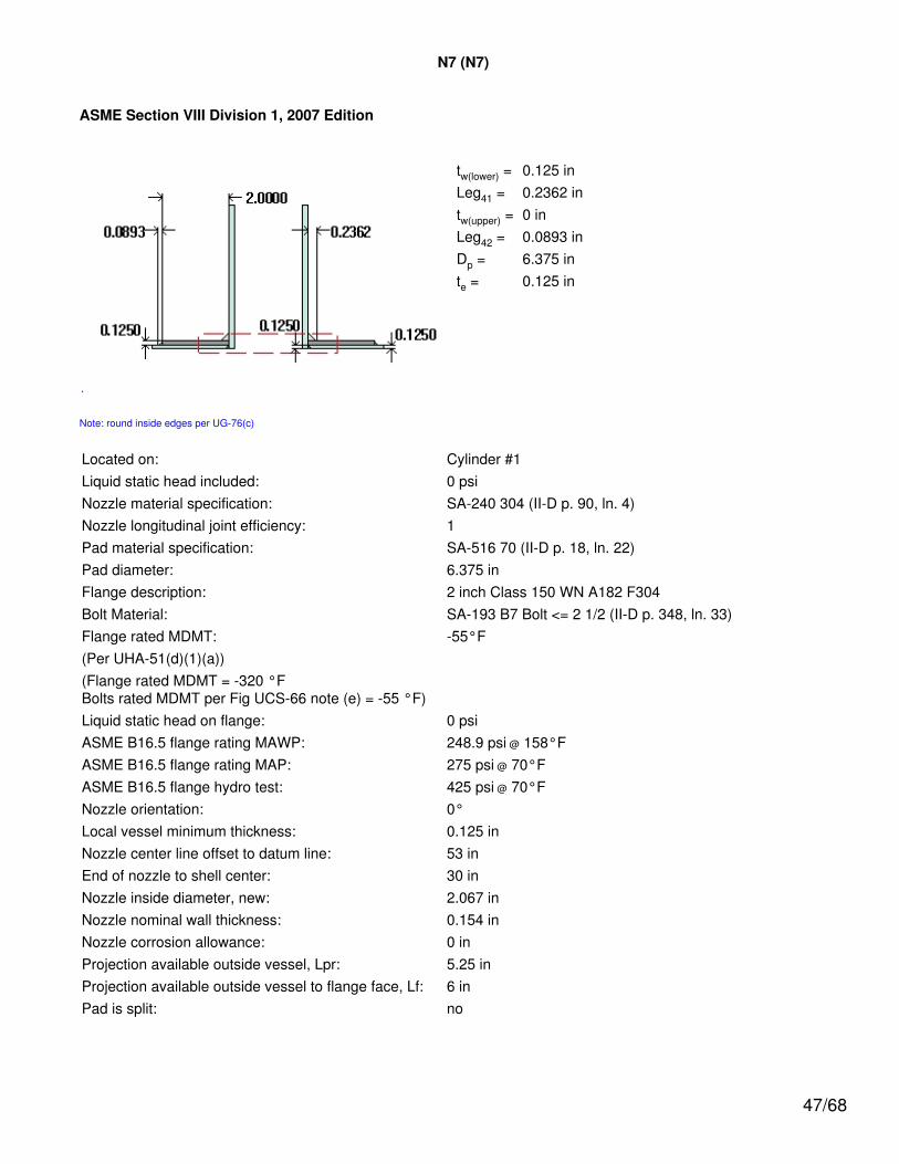
N7 (N7)
ASME Section VIII Division 1, 2007 Edition
tw(lower) = 0.125 inLeg41 = 0.2362 intw(upper) = 0 inLeg42 = 0.0893 inDp = 6.375 inte = 0.125 in
Note: round inside edges per UG-76(c)
Located on: Cylinder #1Liquid static head included: 0 psiNozzle material specification: SA-240 304 (II-D p. 90, ln. 4)Nozzle longitudinal joint efficiency: 1Pad material specification: SA-516 70 (II-D p. 18, ln. 22)Pad diameter: 6.375 inFlange description: 2 inch Class 150 WN A182 F304Bolt Material: SA-193 B7 Bolt <= 2 1/2 (II-D p. 348, ln. 33)Flange rated MDMT: -55°F(Per UHA-51(d)(1)(a))(Flange rated MDMT = -320 °FBolts rated MDMT per Fig UCS-66 note (e) = -55 °F)Liquid static head on flange: 0 psiASME B16.5 flange rating MAWP: 248.9 psi @ 158°FASME B16.5 flange rating MAP: 275 psi @ 70°FASME B16.5 flange hydro test: 425 psi @ 70°FNozzle orientation: 0°Local vessel minimum thickness: 0.125 inNozzle center line offset to datum line: 53 inEnd of nozzle to shell center: 30 inNozzle inside diameter, new: 2.067 inNozzle nominal wall thickness: 0.154 inNozzle corrosion allowance: 0 inProjection available outside vessel, Lpr: 5.25 inProjection available outside vessel to flange face, Lf: 6 inPad is split: no
47/68
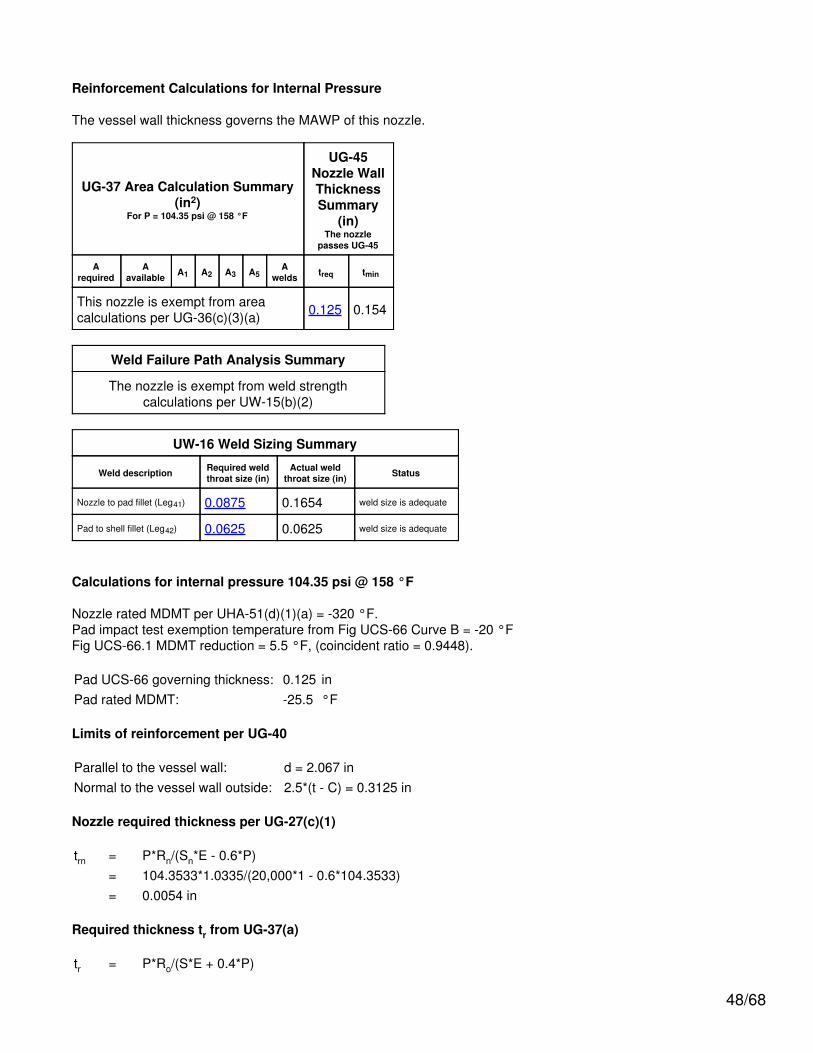
Reinforcement Calculations for Internal Pressure
The vessel wall thickness governs the MAWP of this nozzle.
UG-37 Area Calculation Summary(in2)
For P = 104.35 psi @ 158 °F
UG-45Nozzle WallThicknessSummary
(in)The nozzle
passes UG-45
Arequired
Aavailable A1 A2 A3 A5
Awelds treq tmin
This nozzle is exempt from areacalculations per UG-36(c)(3)(a) 0.125 0.154
Weld Failure Path Analysis Summary
The nozzle is exempt from weld strengthcalculations per UW-15(b)(2)
UW-16 Weld Sizing Summary
Weld description Required weldthroat size (in)
Actual weldthroat size (in) Status
Nozzle to pad fillet (Leg41) 0.0875 0.1654 weld size is adequate
Pad to shell fillet (Leg42) 0.0625 0.0625 weld size is adequate
Calculations for internal pressure 104.35 psi @ 158 °F
Nozzle rated MDMT per UHA-51(d)(1)(a) = -320 °F.Pad impact test exemption temperature from Fig UCS-66 Curve B = -20 °FFig UCS-66.1 MDMT reduction = 5.5 °F, (coincident ratio = 0.9448).
Pad UCS-66 governing thickness: 0.125 inPad rated MDMT: -25.5 °F
Limits of reinforcement per UG-40
Parallel to the vessel wall: d = 2.067 inNormal to the vessel wall outside: 2.5*(t - C) = 0.3125 in
Nozzle required thickness per UG-27(c)(1)
trn = P*Rn/(Sn*E - 0.6*P)= 104.3533*1.0335/(20,000*1 - 0.6*104.3533)= 0.0054 in
Required thickness tr from UG-37(a)
tr = P*Ro/(S*E + 0.4*P)
48/68
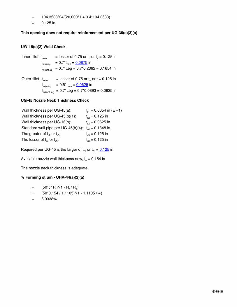
= 104.3533*24/(20,000*1 + 0.4*104.3533)= 0.125 in
This opening does not require reinforcement per UG-36(c)(3)(a)
UW-16(c)(2) Weld Check
Inner fillet: tmin = lesser of 0.75 or tn or te = 0.125 intw(min) = 0.7*tmin = 0.0875 intw(actual) = 0.7*Leg = 0.7*0.2362 = 0.1654 in
Outer fillet: tmin = lesser of 0.75 or te or t = 0.125 intw(min) = 0.5*tmin = 0.0625 intw(actual) = 0.7*Leg = 0.7*0.0893 = 0.0625 in
UG-45 Nozzle Neck Thickness Check
Wall thickness per UG-45(a): tr1 = 0.0054 in (E =1)Wall thickness per UG-45(b)(1): tr2 = 0.125 inWall thickness per UG-16(b): tr3 = 0.0625 inStandard wall pipe per UG-45(b)(4): tr4 = 0.1348 inThe greater of tr2 or tr3: tr5 = 0.125 inThe lesser of tr4 or tr5: tr6 = 0.125 in
Required per UG-45 is the larger of tr1 or tr6 = 0.125 in
Available nozzle wall thickness new, tn = 0.154 in
The nozzle neck thickness is adequate.
% Forming strain - UHA-44(a)(2)(a)
= (50*t / Rf)*(1 - Rf / Ro)= (50*0.154 / 1.1105)*(1 - 1.1105 / ∞)= 6.9338%
49/68
Reinforcement Calculations for MAP
The vessel wall thickness governs the MAP of this nozzle.
UG-37 Area Calculation Summary(in2)
For P = 104.35 psi @ 70 °F
UG-45Nozzle WallThicknessSummary
(in)The nozzle
passes UG-45
Arequired
Aavailable A1 A2 A3 A5
Awelds treq tmin
This nozzle is exempt from areacalculations per UG-36(c)(3)(a) 0.125 0.154
Weld Failure Path Analysis Summary
The nozzle is exempt from weld strengthcalculations per UW-15(b)(2)
UW-16 Weld Sizing Summary
Weld description Required weldthroat size (in)
Actual weldthroat size (in) Status
Nozzle to pad fillet (Leg41) 0.0875 0.1654 weld size is adequate
Pad to shell fillet (Leg42) 0.0625 0.0625 weld size is adequate
Calculations for internal pressure 104.35 psi @ 70 °F
Nozzle rated MDMT per UHA-51(d)(1)(a) = -320 °F.
Limits of reinforcement per UG-40
Parallel to the vessel wall: d = 2.067 inNormal to the vessel wall outside: 2.5*(t - C) = 0.3125 in
Nozzle required thickness per UG-27(c)(1)
trn = P*Rn/(Sn*E - 0.6*P)= 104.3533*1.0335/(20,000*1 - 0.6*104.3533)= 0.0054 in
Required thickness tr from UG-37(a)
tr = P*Ro/(S*E + 0.4*P)= 104.3533*24/(20,000*1 + 0.4*104.3533)= 0.125 in
50/68
This opening does not require reinforcement per UG-36(c)(3)(a)
UW-16(c)(2) Weld Check
Inner fillet: tmin = lesser of 0.75 or tn or te = 0.125 intw(min) = 0.7*tmin = 0.0875 intw(actual) = 0.7*Leg = 0.7*0.2362 = 0.1654 in
Outer fillet: tmin = lesser of 0.75 or te or t = 0.125 intw(min) = 0.5*tmin = 0.0625 intw(actual) = 0.7*Leg = 0.7*0.0893 = 0.0625 in
UG-45 Nozzle Neck Thickness Check
Wall thickness per UG-45(a): tr1 = 0.0054 in (E =1)Wall thickness per UG-45(b)(1): tr2 = 0.125 inWall thickness per UG-16(b): tr3 = 0.0625 inStandard wall pipe per UG-45(b)(4): tr4 = 0.1348 inThe greater of tr2 or tr3: tr5 = 0.125 inThe lesser of tr4 or tr5: tr6 = 0.125 in
Required per UG-45 is the larger of tr1 or tr6 = 0.125 in
Available nozzle wall thickness new, tn = 0.154 in
The nozzle neck thickness is adequate.
51/68

N8 (N8)
ASME Section VIII Division 1, 2007 Edition
tw(lower) = 0.125 inLeg41 = 0.2362 in
Note: round inside edges per UG-76(c)
Located on: Cylinder #1Liquid static head included: 0 psiNozzle material specification: SA-240 304 (II-D p. 90, ln. 4)Nozzle longitudinal joint efficiency: 1Flange description: 0.75 inch Class 300 WN A182 F304Bolt Material: SA-193 B7 Bolt <= 2 1/2 (II-D p. 348, ln. 33)Flange rated MDMT: -55°F(Per UHA-51(d)(1)(a))(Flange rated MDMT = -320 °FBolts rated MDMT per Fig UCS-66 note (e) = -55 °F)Liquid static head on flange: 0 psiASME B16.5 flange rating MAWP: 650.4 psi @ 158°FASME B16.5 flange rating MAP: 720 psi @ 70°FASME B16.5 flange hydro test: 1100 psi @ 70°FNozzle orientation: 0°Local vessel minimum thickness: 0.125 inNozzle center line offset to datum line: 80 inEnd of nozzle to shell center: 30 inNozzle inside diameter, new: 0.742 inNozzle nominal wall thickness: 0.154 inNozzle corrosion allowance: 0 inProjection available outside vessel, Lpr: 5.38 inProjection available outside vessel to flange face, Lf: 6 in
52/68
Reinforcement Calculations for Internal Pressure
The vessel wall thickness governs the MAWP of this nozzle.
UG-37 Area Calculation Summary(in2)
For P = 104.35 psi @ 158 °F
UG-45 NozzleWall
ThicknessSummary (in)The nozzle passes
UG-45
Arequired
Aavailable A1 A2 A3 A5
Awelds treq tmin
This nozzle is exempt from areacalculations per UG-36(c)(3)(a) 0.0989 0.154
Weld Failure Path Analysis Summary
The nozzle is exempt from weld strengthcalculations per UW-15(b)(2)
UW-16 Weld Sizing Summary
Weld description Required weldthroat size (in)
Actual weldthroat size (in) Status
Nozzle to shell fillet (Leg41) 0.0875 0.1654 weld size is adequate
Calculations for internal pressure 104.35 psi @ 158 °F
Nozzle rated MDMT per UHA-51(d)(1)(a) = -320 °F.
Limits of reinforcement per UG-40
Parallel to the vessel wall: d = 0.742 inNormal to the vessel wall outside: 2.5*(t - C) = 0.3125 in
Nozzle required thickness per UG-27(c)(1)
trn = P*Rn/(Sn*E - 0.6*P)= 104.3533*0.371/(20,000*1 - 0.6*104.3533)= 0.0019 in
Required thickness tr from UG-37(a)
tr = P*Ro/(S*E + 0.4*P)= 104.3533*24/(20,000*1 + 0.4*104.3533)= 0.125 in
This opening does not require reinforcement per UG-36(c)(3)(a)
UW-16(c) Weld Check
53/68

Fillet weld: tmin = lesser of 0.75 or tn or t = 0.125 intc(min) = lesser of 0.25 or 0.7*tmin = 0.0875 intc(actual) = 0.7*Leg = 0.7*0.2362 = 0.1654 in
The fillet weld size is satisfactory.
Weld strength calculations are not required for this detail which conforms to Fig. UW-16.1, sketch (c-e).
UG-45 Nozzle Neck Thickness Check
Wall thickness per UG-45(a): tr1 = 0.0019 in (E =1)Wall thickness per UG-45(b)(1): tr2 = 0.125 inWall thickness per UG-16(b): tr3 = 0.0625 inStandard wall pipe per UG-45(b)(4): tr4 = 0.0989 inThe greater of tr2 or tr3: tr5 = 0.125 inThe lesser of tr4 or tr5: tr6 = 0.0989 in
Required per UG-45 is the larger of tr1 or tr6 = 0.0989 in
Available nozzle wall thickness new, tn = 0.154 in
The nozzle neck thickness is adequate.
% Forming strain - UHA-44(a)(2)(a)
= (50*t / Rf)*(1 - Rf / Ro)= (50*0.154 / 0.448)*(1 - 0.448 / ∞)= 17.1875%
54/68

Reinforcement Calculations for MAP
The vessel wall thickness governs the MAP of this nozzle.
UG-37 Area Calculation Summary(in2)
For P = 104.35 psi @ 70 °F
UG-45 NozzleWall
ThicknessSummary (in)The nozzle passes
UG-45
Arequired
Aavailable A1 A2 A3 A5
Awelds treq tmin
This nozzle is exempt from areacalculations per UG-36(c)(3)(a) 0.0989 0.154
Weld Failure Path Analysis Summary
The nozzle is exempt from weld strengthcalculations per UW-15(b)(2)
UW-16 Weld Sizing Summary
Weld description Required weldthroat size (in)
Actual weldthroat size (in) Status
Nozzle to shell fillet (Leg41) 0.0875 0.1654 weld size is adequate
Calculations for internal pressure 104.35 psi @ 70 °F
Nozzle rated MDMT per UHA-51(d)(1)(a) = -320 °F.
Limits of reinforcement per UG-40
Parallel to the vessel wall: d = 0.742 inNormal to the vessel wall outside: 2.5*(t - C) = 0.3125 in
Nozzle required thickness per UG-27(c)(1)
trn = P*Rn/(Sn*E - 0.6*P)= 104.3533*0.371/(20,000*1 - 0.6*104.3533)= 0.0019 in
Required thickness tr from UG-37(a)
tr = P*Ro/(S*E + 0.4*P)= 104.3533*24/(20,000*1 + 0.4*104.3533)= 0.125 in
This opening does not require reinforcement per UG-36(c)(3)(a)
55/68

UW-16(c) Weld Check
Fillet weld: tmin = lesser of 0.75 or tn or t = 0.125 intc(min) = lesser of 0.25 or 0.7*tmin = 0.0875 intc(actual) = 0.7*Leg = 0.7*0.2362 = 0.1654 in
The fillet weld size is satisfactory.
Weld strength calculations are not required for this detail which conforms to Fig. UW-16.1, sketch (c-e).
UG-45 Nozzle Neck Thickness Check
Wall thickness per UG-45(a): tr1 = 0.0019 in (E =1)Wall thickness per UG-45(b)(1): tr2 = 0.125 inWall thickness per UG-16(b): tr3 = 0.0625 inStandard wall pipe per UG-45(b)(4): tr4 = 0.0989 inThe greater of tr2 or tr3: tr5 = 0.125 inThe lesser of tr4 or tr5: tr6 = 0.0989 in
Required per UG-45 is the larger of tr1 or tr6 = 0.0989 in
Available nozzle wall thickness new, tn = 0.154 in
The nozzle neck thickness is adequate.
56/68
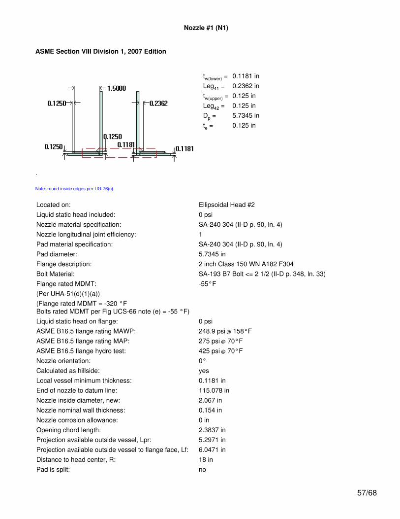
Nozzle #1 (N1)
ASME Section VIII Division 1, 2007 Edition
tw(lower) = 0.1181 inLeg41 = 0.2362 intw(upper) = 0.125 inLeg42 = 0.125 inDp = 5.7345 inte = 0.125 in
Note: round inside edges per UG-76(c)
Located on: Ellipsoidal Head #2Liquid static head included: 0 psiNozzle material specification: SA-240 304 (II-D p. 90, ln. 4)Nozzle longitudinal joint efficiency: 1Pad material specification: SA-240 304 (II-D p. 90, ln. 4)Pad diameter: 5.7345 inFlange description: 2 inch Class 150 WN A182 F304Bolt Material: SA-193 B7 Bolt <= 2 1/2 (II-D p. 348, ln. 33)Flange rated MDMT: -55°F(Per UHA-51(d)(1)(a))(Flange rated MDMT = -320 °FBolts rated MDMT per Fig UCS-66 note (e) = -55 °F)Liquid static head on flange: 0 psiASME B16.5 flange rating MAWP: 248.9 psi @ 158°FASME B16.5 flange rating MAP: 275 psi @ 70°FASME B16.5 flange hydro test: 425 psi @ 70°FNozzle orientation: 0°Calculated as hillside: yesLocal vessel minimum thickness: 0.1181 inEnd of nozzle to datum line: 115.078 inNozzle inside diameter, new: 2.067 inNozzle nominal wall thickness: 0.154 inNozzle corrosion allowance: 0 inOpening chord length: 2.3837 inProjection available outside vessel, Lpr: 5.2971 inProjection available outside vessel to flange face, Lf: 6.0471 inDistance to head center, R: 18 inPad is split: no
57/68
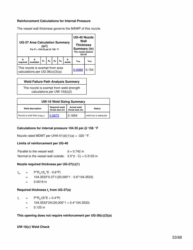
Reinforcement Calculations for Internal Pressure
The vessel wall thickness governs the MAWP of this nozzle.
UG-37 Area Calculation Summary(in2)
For P = 98.81 psi @ 158 °F
UG-45Nozzle WallThicknessSummary
(in)The nozzle
passes UG-45
Arequired
Aavailable A1 A2 A3 A5
Awelds treq tmin
This nozzle is exempt from areacalculations per UG-36(c)(3)(a) 0.118 0.154
Weld Failure Path Analysis Summary
The nozzle is exempt from weld strengthcalculations per UW-15(b)(2)
UW-16 Weld Sizing Summary
Weld description Required weldsize (in)
Actual weldsize (in) Status
Nozzle to pad fillet (Leg41) 0.0875 0.1654 weld size is adequate
Pad to shell fillet (Leg42) 0.0591 0.0875 weld size is adequate
Nozzle to pad groove (Upper) 0.0875 0.125 weld size is adequate
Calculations for internal pressure 98.81 psi @ 158 °F
Nozzle rated MDMT per UHA-51(d)(1)(a) = -320 °F.Pad rated MDMT per UHA-51(d)(1)(a) = -320 °F.
Limits of reinforcement per UG-40
Parallel to the vessel wall: d = 2.3837 inNormal to the vessel wall outside: 2.5*(t - C) = 0.2953 in
Nozzle required thickness per UG-27(c)(1)
trn = P*Rn/(Sn*E - 0.6*P)= 98.8117*1.0335/(20,000*1 - 0.6*98.8117)= 0.0051 in
Required thickness tr from UG-37(a)
tr = P*Do*K / (2*S*E + 2*P*(K - 0.1))= 98.81*48*1 / (2*20,000*1 + 2*98.81*(1 - 0.1))= 0.118"
58/68
This opening does not require reinforcement per UG-36(c)(3)(a)
UW-16(c)(2) Weld Check
Inner fillet: tmin = lesser of 0.75 or tn or te = 0.125 intc(min) = lesser of 0.25 or 0.7*tmin = 0.0875 intc(actual) = 0.7*Leg = 0.7*0.2362 = 0.1654 in
Outer fillet: tmin = lesser of 0.75 or te or t = 0.1181 intw(min) = 0.5*tmin = 0.0591 intw(actual) = 0.7*Leg = 0.7*0.125 = 0.0875 in
UG-45 Nozzle Neck Thickness Check
Interpretation VIII-1-83-66 has been applied.
Wall thickness per UG-45(a): tr1 = 0.0051 in (E =1)Wall thickness per UG-45(b)(1): tr2 = 0.118 inWall thickness per UG-16(b): tr3 = 0.0625 inStandard wall pipe per UG-45(b)(4): tr4 = 0.1348 inThe greater of tr2 or tr3: tr5 = 0.118 inThe lesser of tr4 or tr5: tr6 = 0.118 in
Required per UG-45 is the larger of tr1 or tr6 = 0.118 in
Available nozzle wall thickness new, tn = 0.154 in
The nozzle neck thickness is adequate.
% Forming strain - UHA-44(a)(2)(a)
= (50*t / Rf)*(1 - Rf / Ro)= (50*0.154 / 1.1105)*(1 - 1.1105 / ∞)= 6.9338%
59/68
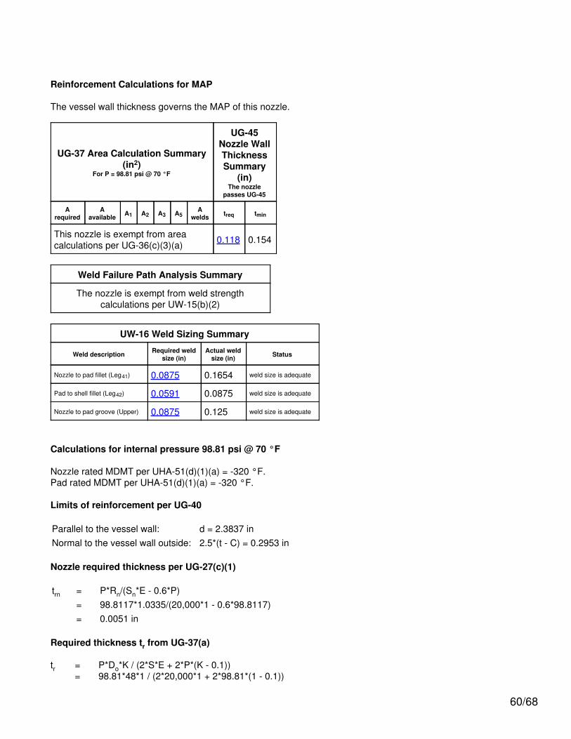
Reinforcement Calculations for MAP
The vessel wall thickness governs the MAP of this nozzle.
UG-37 Area Calculation Summary(in2)
For P = 98.81 psi @ 70 °F
UG-45Nozzle WallThicknessSummary
(in)The nozzle
passes UG-45
Arequired
Aavailable A1 A2 A3 A5
Awelds treq tmin
This nozzle is exempt from areacalculations per UG-36(c)(3)(a) 0.118 0.154
Weld Failure Path Analysis Summary
The nozzle is exempt from weld strengthcalculations per UW-15(b)(2)
UW-16 Weld Sizing Summary
Weld description Required weldsize (in)
Actual weldsize (in) Status
Nozzle to pad fillet (Leg41) 0.0875 0.1654 weld size is adequate
Pad to shell fillet (Leg42) 0.0591 0.0875 weld size is adequate
Nozzle to pad groove (Upper) 0.0875 0.125 weld size is adequate
Calculations for internal pressure 98.81 psi @ 70 °F
Nozzle rated MDMT per UHA-51(d)(1)(a) = -320 °F.Pad rated MDMT per UHA-51(d)(1)(a) = -320 °F.
Limits of reinforcement per UG-40
Parallel to the vessel wall: d = 2.3837 inNormal to the vessel wall outside: 2.5*(t - C) = 0.2953 in
Nozzle required thickness per UG-27(c)(1)
trn = P*Rn/(Sn*E - 0.6*P)= 98.8117*1.0335/(20,000*1 - 0.6*98.8117)= 0.0051 in
Required thickness tr from UG-37(a)
tr = P*Do*K / (2*S*E + 2*P*(K - 0.1))= 98.81*48*1 / (2*20,000*1 + 2*98.81*(1 - 0.1))
60/68

= 0.118"
This opening does not require reinforcement per UG-36(c)(3)(a)
UW-16(c)(2) Weld Check
Inner fillet: tmin = lesser of 0.75 or tn or te = 0.125 intc(min) = lesser of 0.25 or 0.7*tmin = 0.0875 intc(actual) = 0.7*Leg = 0.7*0.2362 = 0.1654 in
Outer fillet: tmin = lesser of 0.75 or te or t = 0.1181 intw(min) = 0.5*tmin = 0.0591 intw(actual) = 0.7*Leg = 0.7*0.125 = 0.0875 in
UG-45 Nozzle Neck Thickness Check
Interpretation VIII-1-83-66 has been applied.
Wall thickness per UG-45(a): tr1 = 0.0051 in (E =1)Wall thickness per UG-45(b)(1): tr2 = 0.118 inWall thickness per UG-16(b): tr3 = 0.0625 inStandard wall pipe per UG-45(b)(4): tr4 = 0.1348 inThe greater of tr2 or tr3: tr5 = 0.118 inThe lesser of tr4 or tr5: tr6 = 0.118 in
Required per UG-45 is the larger of tr1 or tr6 = 0.118 in
Available nozzle wall thickness new, tn = 0.154 in
The nozzle neck thickness is adequate.
61/68

Saddle #1
Saddle material: A 36Saddle construction is: Centered webSaddle allowable stress: Ss = 20,000 psiSaddle yield stress: Sy = 38,000 psiSaddle distance to datum: 10 inTangent to tangent length: L = 102.4252 inSaddle separation: Ls = 78.4252 inVessel radius: R = 24 inTangent distance left: Al = 12 inTangent distance right: Ar = 12 inSaddle height: Hs = 36 inSaddle contact angle: θ = 120 °Web plate thickness: ts = 0.25 inBase plate length: E = 42 inBase plate width: F = 9 inBase plate thickness: tb = 0.375 inNumber of stiffener ribs: n = 3Largest stiffener rib spacing: di = 20.375 inStiffener rib thickness: tw = 0.25 inSaddle width: B = 8 in
Anchor bolt size & type: 1 inch series 8threaded
Anchor bolt material:Anchor bolt allowable shear: 15,000 psiAnchor bolt corrosion allowance: 0 inAnchor bolts per saddle: 2Base coefficient of friction: µ = 0.45
Weight on left saddle: operating corr =391 lb, test new =4,218 lbWeight on right saddle: operating corr =392 lb, test new =4,218 lbWeight of saddle pair =248 lb
62/68
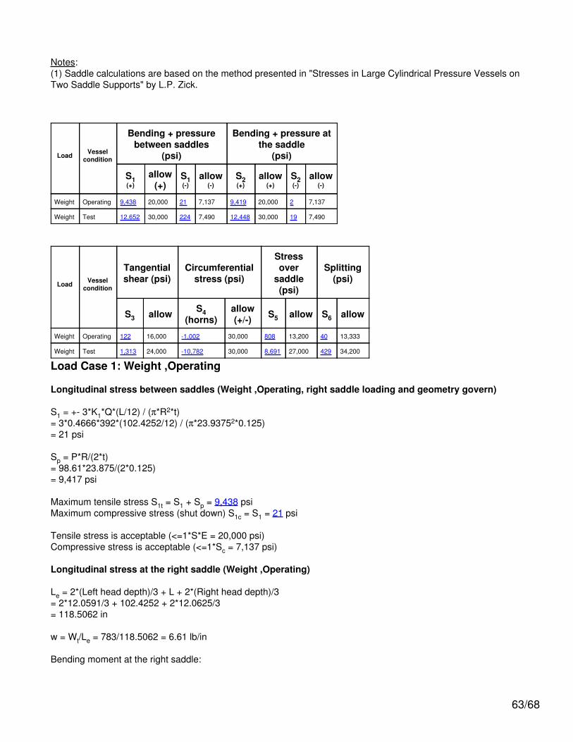
Notes:(1) Saddle calculations are based on the method presented in "Stresses in Large Cylindrical Pressure Vessels onTwo Saddle Supports" by L.P. Zick.
Load Vesselcondition
Bending + pressurebetween saddles
(psi)
Bending + pressure atthe saddle
(psi)
S1(+)
allow(+)
S1(-)
allow(-)
S2(+)
allow(+)
S2(-)
allow(-)
Weight Operating 9,438 20,000 21 7,137 9,419 20,000 2 7,137
Weight Test 12,652 30,000 224 7,490 12,448 30,000 19 7,490
Load Vesselcondition
Tangentialshear (psi)
Circumferentialstress (psi)
Stressover
saddle(psi)
Splitting(psi)
S3 allow S4(horns)
allow(+/-) S5 allow S6 allow
Weight Operating 122 16,000 -1,002 30,000 808 13,200 40 13,333
Weight Test 1,313 24,000 -10,782 30,000 8,691 27,000 429 34,200
Load Case 1: Weight ,Operating
Longitudinal stress between saddles (Weight ,Operating, right saddle loading and geometry govern)
S1 = +- 3*K1*Q*(L/12) / (π*R2*t)= 3*0.4666*392*(102.4252/12) / (π*23.93752*0.125)= 21 psi
Sp = P*R/(2*t)= 98.61*23.875/(2*0.125)= 9,417 psi
Maximum tensile stress S1t = S1 + Sp = 9,438 psiMaximum compressive stress (shut down) S1c = S1 = 21 psi
Tensile stress is acceptable (<=1*S*E = 20,000 psi)Compressive stress is acceptable (<=1*Sc = 7,137 psi)
Longitudinal stress at the right saddle (Weight ,Operating)
Le = 2*(Left head depth)/3 + L + 2*(Right head depth)/3= 2*12.0591/3 + 102.4252 + 2*12.0625/3= 118.5062 in
w = Wt/Le = 783/118.5062 = 6.61 lb/in
Bending moment at the right saddle:
63/68

Mq = w*(2*H*Ar/3 + Ar2/2 - (R2 - H2)/4)
= 6.61*(2*12.0625*12/3 + 122/2 - (242 - 12.06252)/4)= 402.2 lb-in
S2 = +- Mq*K1'/ (π*R2*t)= 402.2*1/ (π*23.93752*0.125)= 2 psi
Sp = P*R/(2*t)= 98.61*23.875/(2*0.125)= 9,417 psi
Maximum tensile stress S2t = S2 + Sp = 9,419 psiMaximum compressive stress (shut down) S2c = S2 = 2 psi
Tensile stress is acceptable (<=1*S = 20,000 psi)Compressive stress is acceptable (<=1*Sc = 7,137 psi)
Tangential shear stress in the shell (left saddle, Weight ,Operating)
S3 = K2.3*Q/(R*(t))= 0.8799*391/(23.9375*(0.125))= 115 psi
Tangential shear stress is acceptable (<= 0.8*S = 16,000 psi)
Tangential shear stress in the left head (Weight ,Operating)
S3 = K2.3*Q/(R*th)= 0.8799*391/(23.9375*0.1181)= 122 psi
Tangential shear stress is acceptable (<= 0.8*S = 16,000 psi)
Additional stress in the head used as a stiffener
S3h = K2.4*Q/(R*th)= 0.4011*391/(23.9375*0.1181)= 55 psi
Sp = P*(K*Di + 0.2*th)/(2*th)= 98.61*(1*47.7638 + 0.2*0.1181)/(2*0.1181)= 19,951 psi
Total stress in the head = S3h + Sp = 20,006 psi
Stress in the head is acceptable (<= 1.25*Sh = 25,000 psi)
Circumferential stress at the right saddle horns (Weight ,Operating)
S4 = -Q/(4*t*(b+1.56*Sqr(Ro*t))) - 12*K3*Q*R/(L*t2)= -392/(4*0.125*(8+1.56*Sqr(24*0.125))) - 12*0.0132*392*23.9375/(102.4252*0.1252)= -1,002 psi
Circumferential stress at saddle horns is acceptable (<=1.5*Sa = 30,000 psi)
Ring compression in shell over right saddle (Weight ,Operating)
64/68
S5 = K5*Q/((t)*(ts + 1.56*Sqr(Ro*tc)))= 0.7603*392/((0.125)*(0.25 + 1.56*Sqr(24*0.125)))= 808 psi
Ring compression in shell is acceptable (<= 0.5*Sy = 13,200 psi)
Saddle splitting load (right, Weight ,Operating)
Area resisting splitting force = Web area + wear plate area
Ae = Heff*ts + tp*Wp= 8*0.25 + 0*0= 2 in2
S6 = K8*Q / Ae= 0.2035*392 / 2= 40 psi
Stress in saddle is acceptable (<= (2/3)*Ss = 13,333 psi)
Load Case 2: Weight ,Test
Longitudinal stress between saddles (Weight ,Test, right saddle loading and geometry govern)
S1 = +- 3*K1*Q*(L/12) / (π*R2*t)= 3*0.4666*4,218*(102.4252/12) / (π*23.93752*0.125)= 224 psi
Sp = P*R/(2*t)= 130.14*23.875/(2*0.125)= 12,428 psi
Maximum tensile stress S1t = S1 + Sp = 12,652 psiMaximum compressive stress (shut down) S1c = S1 = 224 psi
Tensile stress is acceptable (<= 0.9*Sy = 30,000 psi)Compressive stress is acceptable (<=1*Sc = 7,490 psi)
Longitudinal stress at the right saddle (Weight ,Test)
Le = 2*(Left head depth)/3 + L + 2*(Right head depth)/3= 2*12.0591/3 + 102.4252 + 2*12.0625/3= 118.5062 in
w = Wt/Le = 8,436/118.5062 = 71.19 lb/in
Bending moment at the right saddle:
Mq = w*(2*H*Ar/3 + Ar2/2 - (R2 - H2)/4)
= 71.19*(2*12.0625*12/3 + 122/2 - (242 - 12.06252)/4)= 4,333.5 lb-in
S2 = +- Mq*K1'/ (π*R2*t)= 4,333.5*1/ (π*23.93752*0.125)= 19 psi
65/68
Sp = P*R/(2*t)= 130.14*23.875/(2*0.125)= 12,428 psi
Maximum tensile stress S2t = S2 + Sp = 12,448 psiMaximum compressive stress (shut down) S2c = S2 = 19 psi
Tensile stress is acceptable (<= 0.9*Sy = 30,000 psi)Compressive stress is acceptable (<=1*Sc = 7,490 psi)
Tangential shear stress in the shell (left saddle, Weight ,Test)
S3 = K2.3*Q/(R*(t))= 0.8799*4,218/(23.9375*(0.125))= 1,240 psi
Tangential shear stress is acceptable (<= 0.8*(0.9*Sy) = 24,000 psi)
Tangential shear stress in the left head (Weight ,Test)
S3 = K2.3*Q/(R*th)= 0.8799*4,218/(23.9375*0.1181)= 1,313 psi
Tangential shear stress is acceptable (<= 0.8*(0.9*Sy) = 24,000 psi)
Additional stress in the head used as a stiffener
S3h = K2.4*Q/(R*th)= 0.4011*4,218/(23.9375*0.1181)= 598 psi
Sp = P*(K*Di + 0.2*th)/(2*th)= 130.14*(1*47.7638 + 0.2*0.1181)/(2*0.1181)= 26,329 psi
Total stress in the head = S3h + Sp = 26,928 psi
Stress in the head is acceptable (<= 0.9*Sy = 30,000 psi)
Circumferential stress at the right saddle horns (Weight ,Test)
S4 = -Q/(4*t*(b+1.56*Sqr(Ro*t))) - 12*K3*Q*R/(L*t2)= -4,218/(4*0.125*(8+1.56*Sqr(24*0.125))) - 12*0.0132*4,218*23.9375/(102.4252*0.1252)= -10,782 psi
Circumferential stress at saddle horns is acceptable (<= 0.9*Sy = 30,000 psi)
Ring compression in shell over right saddle (Weight ,Test)
S5 = K5*Q/((t)*(ts + 1.56*Sqr(Ro*tc)))= 0.7603*4,218/((0.125)*(0.25 + 1.56*Sqr(24*0.125)))= 8,691 psi
Ring compression in shell is acceptable (<= 0.9*Sy = 27,000 psi)
Saddle splitting load (right, Weight ,Test)
66/68
Area resisting splitting force = Web area + wear plate area
Ae = Heff*ts + tp*Wp= 8*0.25 + 0*0= 2 in2
S6 = K8*Q / Ae= 0.2035*4,218 / 2= 429 psi
Stress in saddle is acceptable (<= 0.9*Sy = 34,200 psi)
Shear stress in anchor bolting, one end slotted
Maximum seismic or wind base shear = 0 lbf
Thermal expansion base shear = W*µ = 516 * 0.45= 232.2 lbf
Corroded root area for a 1 inch series 8 threaded bolt = 0.551 in2 ( 2 per saddle )
Bolt shear stress = 232.2/(0.551*2) = 211 psi
Anchor bolt stress is acceptable (<= 15,000 psi)
Web plate buckling check (Escoe pg 251)
Allowable compressive stress Sc is the lesser of 20,000 or 5,051 psi: (5,051)
Sc = Ki*π2*E/(12*(1 - 0.32)*(di/tw)2)= 1.28*π2*29E+06/(12*(1 - 0.32)*(20.375/0.25)2)= 5,051 psi
Allowable compressive load on the saddle
be = di*ts/(di*ts + 2*tw*(b - 1))= 20.375*0.25/(20.375*0.25 + 2*0.25*(8 - 1))= 0.5927
Fb = n*(As + 2*be*tw)*Sc= 3*(1.9375 + 2*0.5927*0.25)*5,051= 33,849.15 lbf
Saddle loading of 4,342 lbf is <= Fb; satisfactory.
Primary bending + axial stress in the saddle due to end loads (assumes one saddle slotted)σb = V * (Hs - xo)* y / I + Q / A= 0 * (36 - 19.8478)* 4 / 32.01 + 392 / 16.2048= 24 psi
The primary bending + axial stress in the saddle <= 20,000 psi; satisfactory.
Secondary bending + axial stress in the saddle due to end loads (includes thermal expansion, assumes onesaddle slotted)σb = V * (Hs - xo)* y / I + Q / A= 232.2 * (36 - 19.8478)* 4 / 32.01 + 392 / 16.2048= 493 psi
67/68
The secondary bending + axial stress in the saddle < 2*Sy= 76,000 psi; satisfactory.
Saddle base plate thickness check (Roark sixth edition, Table 26, case 7a)
where a = 20.375, b = 4.375 in
tb = (β1*q*b2/(1.5*Sa))0.5
= (3*11*4.3752/(1.5*20,000))0.5
= 0.1483 in
The base plate thickness of 0.375 in is adequate.
Foundation bearing check
Sf = Qmax / (F*E)= 4,342 / (9*42)= 11 psi
Concrete bearing stress < 1,658 psi ; satisfactory.
68/68
![chem senses2019 [Kompatibilit si m d])Temporal lobe epilepsy: dysosmia (cacosmia) Phylogenetic reduction in the relative size of olfactory system Odorant qualities – odorant classes](https://img.pdfslide.net/doc/110x75/5e41510be0664434e7498452/chem-senses2019-kompatibilit-si-m-d-temporal-lobe-epilepsy-dysosmia-cacosmia.jpg)