Embed Size (px)
Citation preview

CGA cooling only/CXA heat pumpVGA cooling only/VXA heat pumpSizes: 075-100-120-150-200-240
Odyssey™ air-cooled chillers and heat pumps
CG-PRC006-E4May 2012

2 CG-PRC006-E4© 2012 Trane
Designed with your needs in mind
TRANE Odyssey™ chillers and heat pumps represent a totally new approach to design products for the TRANE company. The design team’s mission is…to bring a system to the marketplace that will meet your job requirements every time.TRANE’s experienced design team used the newest computer technology and an entirely new manufacturing process to develop a new standard in chillers.Couple the TRANE reputation for quality and reliability in chillers with improvements in efficiency, flexibility and installation ease…and you have systems that will give you “Simply the best value”
3CG-PRC006-E4
Contents
3
Designed with your needs in mind 2
Features And Benefits 4
General Data 5
Application Considerations 9
Performance Data 10
Mechanical Specifications 11

CG-PRC006-E44
Features and benefits
CGA-CXA-VGA-VXA unit features
• Scroll compressor with:- Sound-proofing- Protection of compressor motor winding- Crankcase heater (CXA/VXA)- Thermo-magnetic circuit-breaker1 compressor on sizes 075 to 120, 2 compressors on sizes 150 to 240• Axial fans with low noise level completely
integrated 1 fan on sizes 075 to 120, 2 fans on sizes 150 to 240
• Stainless steel brazed plate water heat exchanger equipped with heating resistor
• Aluminium fin coils with copper tubes• Cooling circuits with:- R407C refrigerant operating charge - Thermostatic expansion valve(s)- Liquid line filter drier(s)- High and low pressure cut-outs1 refrigerant circuit on sizes 075 to 120, 2 refrigerant circuits on sizes 150 to 240• Disconnect switch• Water flow switch• Low ambient dual speed fan• Water outlet low temperature
(+12°C / -12°C)
Accessories• Contactors for pump• Remote control module.
Options• Black epoxy fins• High and low pressure gauges
ControlMicroprocessor control module featuring:- Liquid crystal display indicating return
water temperature; codes of any faults- Control of operating parameters- Possibility of remote fault signaling on
24 V indicator light- Anti-freeze protection of evaporators- Control of defrosting (CXA/VXA only)
VGA-VXA unit additional features
Packaged hydraulic circuit for easier and quicker installation:- Water pump- Water tank: 80 l (sizes 075 -100), 90 l
(size 120) or 150 l (sizes 150- 200-240)- 35 l expansion vessel- Water flow switch- Relief valve-pressure gauge assembly- Automatic air venting- High pressure safety valve set at 3 bars
CG-PRC006-E4 5
General Data
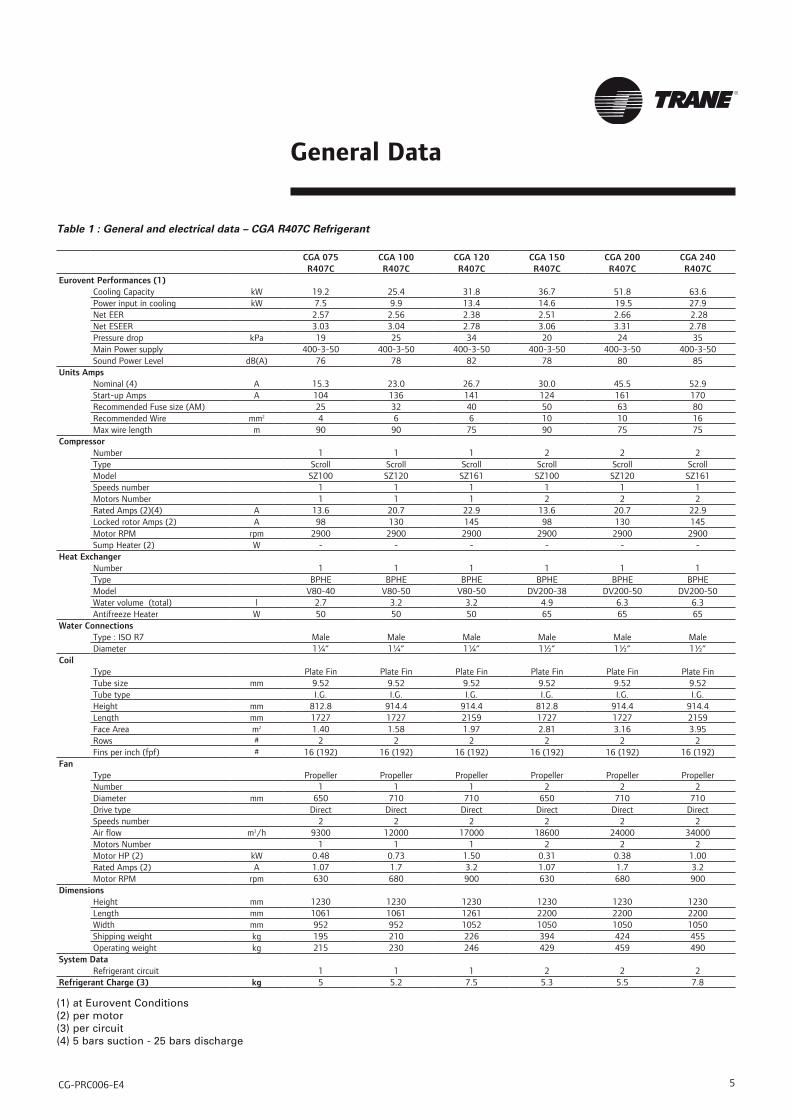
Table 1 : General and electrical data – CGA R407C Refrigerant
CGA 075 CGA 100 CGA 120 CGA 150 CGA 200 CGA 240R407C R407C R407C R407C R407C R407C
Eurovent Performances (1)Cooling Capacity kW 19.2 25.4 31.8 36.7 51.8 63.6Power input in cooling kW 7.5 9.9 13.4 14.6 19.5 27.9Net EER 2.57 2.56 2.38 2.51 2.66 2.28Net ESEER 3.03 3.04 2.78 3.06 3.31 2.78Pressure drop kPa 19 25 34 20 24 35Main Power supply 400-3-50 400-3-50 400-3-50 400-3-50 400-3-50 400-3-50Sound Power Level dB(A) 76 78 82 78 80 85
Units AmpsNominal (4) A 15.3 23.0 26.7 30.0 45.5 52.9Start-up Amps A 104 136 141 124 161 170Recommended Fuse size (AM) 25 32 40 50 63 80Recommended Wire mm2 4 6 6 10 10 16Max wire length m 90 90 75 90 75 75
CompressorNumber 1 1 1 2 2 2Type Scroll Scroll Scroll Scroll Scroll ScrollModel SZ100 SZ120 SZ161 SZ100 SZ120 SZ161Speeds number 1 1 1 1 1 1Motors Number 1 1 1 2 2 2Rated Amps (2)(4) A 13.6 20.7 22.9 13.6 20.7 22.9Locked rotor Amps (2) A 98 130 145 98 130 145Motor RPM rpm 2900 2900 2900 2900 2900 2900Sump Heater (2) W - - - - - -
Heat ExchangerNumber 1 1 1 1 1 1Type BPHE BPHE BPHE BPHE BPHE BPHEModel V80-40 V80-50 V80-50 DV200-38 DV200-50 DV200-50Water volume (total) l 2.7 3.2 3.2 4.9 6.3 6.3Antifreeze Heater W 50 50 50 65 65 65
Water Connections Type : ISO R7 Male Male Male Male Male MaleDiameter 1¼” 1¼” 1¼” 1½” 1½” 1½”
CoilType Plate Fin Plate Fin Plate Fin Plate Fin Plate Fin Plate FinTube size mm 9.52 9.52 9.52 9.52 9.52 9.52Tube type I.G. I.G. I.G. I.G. I.G. I.G.Height mm 812.8 914.4 914.4 812.8 914.4 914.4Length mm 1727 1727 2159 1727 1727 2159Face Area m2 1.40 1.58 1.97 2.81 3.16 3.95Rows # 2 2 2 2 2 2Fins per inch (fpf) # 16 (192) 16 (192) 16 (192) 16 (192) 16 (192) 16 (192)
FanType Propeller Propeller Propeller Propeller Propeller PropellerNumber 1 1 1 2 2 2Diameter mm 650 710 710 650 710 710Drive type Direct Direct Direct Direct Direct DirectSpeeds number 2 2 2 2 2 2Air flow m3/h 9300 12000 17000 18600 24000 34000Motors Number 1 1 1 2 2 2Motor HP (2) kW 0.48 0.73 1.50 0.31 0.38 1.00Rated Amps (2) A 1.07 1.7 3.2 1.07 1.7 3.2Motor RPM rpm 630 680 900 630 680 900
DimensionsHeight mm 1230 1230 1230 1230 1230 1230Length mm 1061 1061 1261 2200 2200 2200Width mm 952 952 1052 1050 1050 1050Shipping weight kg 195 210 226 394 424 455Operating weight kg 215 230 246 429 459 490
System DataRefrigerant circuit 1 1 1 2 2 2
Refrigerant Charge (3) kg 5 5.2 7.5 5.3 5.5 7.8
(1) at Eurovent Conditions(2) per motor(3) per circuit(4) 5 bars suction - 25 bars discharge

CG-PRC006-E46
General Data
Table 2 : General and electrical data – CXA R407C Refrigerant
CXA 075 CXA 100 CXA 120 CXA 150 CXA 200 CXA 240R407C R407C R407C R407C R407C R407C
Eurovent Performances (1)Cooling Capacity kW 19.8 23.2 31.4 38.8 51.8 64.2Power input in cooling kW 8.2 9.7 14.3 15.6 19.9 27.3Net EER 2.41 2.38 2.19 2.48 2.60 2.35Net ESEER 2.88 2.85 2.59 3.05 3.24 2.89Pressure drop in cooling kPa 18 24 32 20 22 32Heating Capacity kW 19.0 25.4 31.3 38.1 50.9 62.5Power input in heating kW 8.1 10.7 14.1 16.0 21.2 28.0Net COP 2.62 2.61 2.55 2.62 2.61 2.57Pressure drop in heating kPa 22.0 31.0 45.0 24.0 27.0 41.0Main Power supply 400-3-50 400-3-50 400-3-50 400-3-50 400-3-50 400-3-50Sound Power Level dB(A) 76 78 82 78 80 85
Units AmpsNominal (4) A 15.4 23.2 26.9 30.1 45.6 53.0Start-up Amps A 104 136 141 124 161 170Recommended Fuse size (AM) 25 32 40 50 63 63Recommended Wire mm2 4 6 6 10 10 16Max wire length m 90 90 75 90 75 75
CompressorNumber 1 1 1 2 2 2Type Scroll Scroll Scroll Scroll Scroll ScrollModel SZ100 SZ120 SZ161 SZ100 SZ120 SZ161Speeds number 1 1 1 1 1 1Motors Number 1 1 1 2 2 2Rated Amps (2)(4) A 13.6 20.7 22.9 13.6 20.7 22.9Locked rotor Amps (2) A 98 130 145 98 130 145Motor RPM rpm 2900 2900 2900 2900 2900 2900Sump Heater (2) W 50 50 50 50 50 50
Heat ExchangerType BPHE BPHE BPHE BPHE BPHE BPHEModel V80-40 V80-50 V80-50 DV200-38 DV200-50 DV200-50Water volume (total) l 2.7 3.2 3.2 4.9 6.3 6.3Antifreeze Heater W 50 50 50 65 65 65
Water Connections Type : ISO R7 Male Male Male Male Male MaleDiameter inch 1¼” 1¼” 1¼” 1½” 1½” 1½”
CoilType Plate Fin Plate Fin Plate Fin Plate Fin Plate Fin Plate FinTube size mm 9.52 9.52 9.52 9.52 9.52 9.52Tube type I.G. I.G. I.G. I.G. I.G. I.G.Height mm 812.8 914.4 914.4 812.8 914.4 914.4Length mm 1727 1727 2159 1727 1727 2159Face Area m2 1.40 1.58 1.97 2.81 3.16 3.95Rows # 2 2 2 2 2 2Fins per inch (fpf) # 16 (192) 16 (192) 16 (192) 16 (192) 16 (192) 16 (192)
FanType Propeller Propeller Propeller Propeller Propeller PropellerNumber 1 1 1 2 2 2Diameter mm 650 710 710 650 710 710Drive type Direct Direct Direct Direct Direct DirectSpeeds number 1 1 1 1 1 1Air flow m3/h 9300 12000 17000 18600 24000 34000Motors Number 1 1 1 2 2 2Motor HP (2) kW 0.48 0.73 1.50 0.31 0.38 1.00Rated Amps (2) A 1.07 1.7 3.2 1.07 1.7 3.2Motor RPM rpm 630 680 900 630 680 900
DimensionsHeight mm 1230 1230 1230 1230 1230 1230Length mm 1061 1061 1261 2200 2200 2200Width mm 952 952 1052 1050 1050 1050Shipping weight kg 201 216 232 406 436 468Operating weight kg 221 236 252 441 471 503
System DataRefrigerant circuit 1 1 1 2 2 2
Refrigerant Charge (3) kg 5.7 5.3 6.3 5.4 5.3 6.3
(1) at Eurovent Conditions(2) per motor(3) per circuit(4) 5 bars suction - 25 bars discharge

CG-PRC006-E4
General Data
7
Table 3 : General and electrical data – VGA R407C Refrigerant
VGA 075 VGA 100 VGA 120 VGA 150 VGA 200 VGA 240R407C R407C R407C R407C R407C R407C
Eurovent Performances (1)Cooling Capacity kW 19.6 26.0 32.3 37.6 52.9 64.7Power input in cooling kW 7.6 10.0 13.4 15.1 19.9 28.2Net EER 2.59 2.61 2.42 2.50 2.66 2.29Net ESEER 3.07 3.09 2.84 3.06 3.31 2.78Pressure available in Cooling kPa 135 110 82 180 158 118Main Power supply 400-3-50 400-3-50 400-3-50 400-3-50 400-3-50 400-3-50Sound Power Level dB(A) 76 78 82 78 80 85
Units AmpsNominal (4) A 16.9 24.6 28.3 32.6 48.1 55.5Start-up Amps A 104 136 141 124 161 170Recommended Fuse size (AM) 25 32 40 50 63 80Recommended Wire mm2 4 6 6 10 10 16Max wire length m 90 90 75 90 75 75
CompressorNumber 1 1 1 2 2 2Type Scroll Scroll Scroll Scroll Scroll ScrollModel SZ100 SZ120 SZ161 SZ100 SZ120 SZ161Speeds number 1 1 1 1 1 1Motors Number 1 1 1 2 2 2Rated Amps (2)(4) A 13.6 20.7 22.9 13.6 20.7 22.9Locked rotor Amps (2) A 98 130 145 98 130 145Motor RPM rpm 2900 2900 2900 2900 2900 2900Sump Heater (2) W - - - - - -
Heat ExchangerType BPHE BPHE BPHE BPHE BPHE BPHEModel V80-40 V80-50 V80-50 DV200-38 DV200-50 DV200-50Water volume (total) l 93 93 103 185 186 186Antifreeze Heater W - - - - - -
Water Connections Type : ISO R7 Male Male Male Male Male MaleDiameter 1”1/2 1”1/2 1”1/2 1”1/2 1”1/2 1”1/2
Water pumpType Multi-cell Multi-cell Multi-cell Single stage Single stage Single stageModel MHIL 502–E–3 MHIL 502–E–3 MHIL 502–E– 3 BAC40-136-1,1/2 BAC40-136-1,1/2 BAC40-136-1,1/2Motor kW 0.55 0.55 0.55 1.1 1.1 1.1Power factor 0.74 0.74 0.74 0.8 0.8 0.8Rated Amps A 1.7 1.7 1.7 2.8 2.8 2.8Locked rotor Amps A 3.0 3.0 3.0 5.3 5.3 5.3
CoilType Plate Fin Plate Fin Plate Fin Plate Fin Plate Fin Plate FinTube size mm 9.52 9.52 9.52 9.52 9.52 9.52Tube type I.G. I.G. I.G. I.G. I.G. I.G.Height mm 812.8 914.4 914.4 812.8 914.4 914.4Length mm 1727 1727 2159 1727 1727 2159Face Area m2 1.40 1.58 1.97 2.81 3.16 3.95Rows # 2 2 2 2 2 2Fins per inch (fpf) # 16 (192) 16 (192) 16 (192) 16 (192) 16 (192) 16 (192)
FanType Propeller Propeller Propeller Propeller Propeller PropellerNumber 1 1 1 2 2 2Diameter mm 650 710 710 650 710 710Drive type Direct Direct Direct Direct Direct DirectSpeeds number 2 2 2 2 2 2Air flow m3/h 9300 12000 17000 18600 24000 34000Motors Number 1 1 1 1 1 1Motor HP (2) kW 0.48 0.73 1.50 0.31 0.38 1.00Rated Amps (2) A 1.07 1.7 3.2 1.07 1.7 3.2Motor RPM rpm 630 680 900 630 680 900
DimensionsHeight mm 1732 1732 1732 1732 1732 1732Length mm 1061 1061 1261 2200 2200 2200Width mm 952 952 1052 1050 1050 1050Shipping weight kg 399 414 430 690 720 750Operating weight kg 419 434 450 710 740 770
System DataRefrigerant circuit 1 1 1 2 2 2
Refrigerant Charge (3) kg 5 5.2 7.5 5.3 5.5 7.8
(1) at Eurovent Conditions(2) per motor(3) per circuit(4) 5 bars suction - 25 bars discharge

CG-PRC006-E48
General Data
Table 4 : General and electrical data – VXA R407C Refrigerant
VXA 075 VXA 100 VXA 120 VXA 150 VXA 200 VXA 240R407C R407C R407C R407C R407C R407C
Eurovent Performances (1)Cooling Capacity kW 20.3 23.8 31.9 39.8 52.9 65.4Power input in cooling kW 8.1 9.6 14.1 15.5 19.7 27.1Net EER 2.45 2.43 2.24 2.46 2.61 2.36Net ESEER 2.91 2.90 2.64 3.05 3.24 2.89Pressure available in Cooling kPa 135 110 82 180 160 120Heating Capacity kW 19.0 25.5 31.5 38.1 51.1 63.0Power input in heating kW 8.1 10.7 14.1 16.0 21.2 28.0Net COP 2.73 2.69 2.62 2.73 2.70 2.64Pressure available in heating kPa 125 80 65 181 158 124Main Power supply 400-3-50 400-3-50 400-3-50 400-3-50 400-3-50 400-3-50Sound Power Level dB(A) 76 78 82 78 80 85
Units AmpsNominal (4) A 16.9 24.6 28.3 32.6 48.1 55.5Start-up Amps A 104 136 141 124 161 170Recommended Fuse size (AM) 25 32 40 50 63 63Recommended Wire mm2 4 6 6 10 10 16Max wire length m 90 90 75 90 75 75
CompressorNumber 1 1 1 2 2 2Type Scroll Scroll Scroll Scroll Scroll ScrollModel SZ100 SZ120 SZ161 SZ100 SZ120 SZ161Speeds number 1 1 1 1 1 1Motors Number 1 1 1 2 2 2Rated Amps (2)(4) A 13.6 20.7 22.9 13.6 20.7 22.9Locked rotor Amps (2) A 98 130 145 98 130 145Motor RPM rpm 2900 2900 2900 2900 2900 2900Sump Heater (2) W 50 50 50 50 50 50
Heat ExchangerType BPHE BPHE BPHE BPHE BPHE BPHEModel V80-40 V80-50 V80-50 DV200-38 DV200-50 DV200-50Water volume (total) l 93 93 103 185 186 186Antifreeze Heater W - - - - - -
Water pumpType Multi-cell Multi-cell Multi-cell Single stage Single stage Single stageModel MHIL502-E-3 MHIL502-E-3 MHIL502-E-3 BAC40-136-1.1/2 BAC40-136-1.1/2 BAC40-136-1.1/2Motor kW 0.55 0.55 0.55 1.1 1.1 1.1Power factor 0.74 0.74 0.74 0.8 0.8 0.8Rated Amps A 1.7 1.7 1.7 2.8 2.8 2.8Locked rotor Amps A 3.0 3.0 3.0 5.3 5.3 5.3
Water Connections Type : ISO R7 Male Male Male Male Male MaleDiameter inch 1”1/2 1”1/2 1”1/2 1”1/2 1”1/2 1”1/2
CoilType Plate Fin Plate Fin Plate Fin Plate Fin Plate Fin Plate FinTube size mm 9.52 9.52 9.52 9.52 9.52 9.52Tube type I.G. I.G. I.G. I.G. I.G. I.G.Height mm 812.8 914.4 914.4 812.8 914.4 914.4Length mm 1727 1727 2159 1727 1727 2159Face Area m2 1.40 1.58 1.97 2.81 3.16 3.95Rows # 2 2 2 2 2 2Fins per inch (fpf) # 16 (192) 16 (192) 16 (192) 16 (192) 16 (192) 16 (192)
FanType Propeller Propeller Propeller Propeller Propeller PropellerNumber 1 1 1 2 2 2Diameter mm 650 710 710 650 710 710Drive type Direct Direct Direct Direct Direct DirectSpeeds number 1 1 1 1 1 1Air flow m3/h 9300 12000 17000 18600 24000 34000Motors Number 1 1 1 2 2 2Motor HP (2) kW 0.48 0.73 1.50 0.31 0.38 1.00Rated Amps (2) A 1.07 1.7 3.2 1.07 1.7 3.2Motor RPM rpm 630 680 900 630 680 900
DimensionsHeight mm 1732 1732 1732 1732 1732 1732Length mm 1061 1061 1261 2200 2200 2200Width mm 952 952 1052 1050 1050 1050Shipping weight kg 399 414 430 702 732 762Operating weight kg 419 434 450 722 752 782
System DataRefrigerant circuit 1 1 1 2 2 2
Refrigerant Charge (3) kg 5.7 5.3 6.3 5.4 5.3 6.3
(1) at Eurovent Conditions(2) per motor(3) per circuit(4) 5 bars suction - 25 bars discharge

CG-PRC006-E4
Application Considerations
Application of this product should be within the catalogued waterflow and performance consideration.
Clearance requirementsVertical condenser air discharge and condenser coil inlet must be unobstructed.
The recommended clearances identified with unit dimensions should be maintained to assure adequate serviceability, maximum capacity and peak operating efficiency. Actual clearances that appear inadequate should be reviewed with the local TRANE representative.
Table 5 - Normal operating limits
Outdoor ambient temperatureUnits Cooling mode Heating modeCXA-VXA Mini. 15°C -15°CCGA-VGA Mini -10°C -CGA-CXA-VGA-VXA Maxi. 45°C 20°C
Leaving water temperatureUnits Cooling mode Heating modeCXA-VXA Mini. -12°C 30°CCXA-VXA Maxi. 15°C 50°CCGA-VGA Mini. -12°C -CGA-VGA Maxi. 15°C -
Operating limits
9

CG-PRC006-E410
Performance Data
Figure 1 CGA-CXA 075 to 240 Evaporator Pressure Drop
Figure 2 VGA/VXA 075 to 120 Water Pump Performances
0
2
4
6
8
10
12
14
16
18
20
0 1 2 3 4 5 6 7 8 9 100
0.1
0.2
0.3
0.4
0.5
Pres
sure
Dro
p (k
Pa)
Water Flow (l/s)
M a
nom
etric
hea
d (m
)
Water flow (m3/h)
Pow
er c
onsu
mpt
ion
(kW
)Power consumption
Manometric head
Figure 3 VGA/VXA 150 to 240 Water Pump Performances
M a
nom
etric
hea
d (m
)
Water flow (m3/h)
Pow
er c
onsu
mpt
ion
(kW
)
Manometric head
Power consumption

CG-PRC006-E4 11
Mechanical SpecificationsCGA/CXA/VGA/VXA R407C
GeneralUnits shall be assembled on heavy gauge steel mounting/lifting rails and shall be weather proofed. Unit shall include scroll compressor(s), plate fin condenser coil, brazed plate heat exchangers fans and motors, and operating charge of R407C refrigerant. Operating range shall be between -10°C and + 45°C in cooling and down to -15°C in heating as standard from factory. Units shall be certified and rated in accordance with Eurovent standard.
CasingUnit casing shall be constructed of galvanized steel. Exterior surfaces shall be cleaned, phosphatized and finished with a weather-resistant baked enamel finish. Units surface shall be tested 500 hours in salt spray test. Units shall have removable end panels which allow access to all major components and controls.
Refrigeration System - Single CompressorSize 075, 100 and 120 units shall have a single refrigeration circuit. This refrigeration circuit has an integral subcooling circuit. A filter drier, expansion valve and check valves shall be provided as standard. Units shall have both a liquid line and suction gas line with gauge port.Units shall have one scroll compressor. Motor shall be suction gas-cooled and shall have a voltage utilization range of plus or minus 10 percent of nameplate voltage. Temperature and current-sensitive motor overloads shall be included for maximum protection.
Refrigeration System - Dual CompressorSize 150, 200 and 240 units shall have two separate and independent refrigeration circuits. Each refrigeration circuit shall have an integral subcooling circuit. A filter drier shall be provided as standard. Units shall have both a liquid line and suction gas line with gauge ports. Each refrigeration circuit is controlled by one thermostatic expansion valve.Units shall have two scroll compressors. Motor shall be suction gas-cooled and shall have a voltage utilization range of plus or minus 10 percent of nameplate voltage. Internal temperature and current-sensitive motor overloads shall be included for maximum protection.
Air exchangerCoils shall be inner groove 9.52 mm copper tubes mechanically bonded to configured aluminum fin as standard. Coil shall be factory pressure and leak tested to 30 bar air pressure.
Water exchangerShall be of the stainless steel brazed plates type. Evaporator shall include thermal insulation and anti-freeze protection. A differential pressostat shall ensure the water flow control. Differential pressostat shall be freeze protected.
Air exchanger FansDirect-drive, statically and dynamically balanced propeller fan(s) with polypropylene reinforced with 30% fiberglass blades and aluminum hub shall be used in draw-through vertical discharge position. Permanently lubricated totally enclosed type motors shall be provided and shall be protected by a circuit breaker. Motor(s) shall have ball bearings for helicoidal fan application type and shall be IP55, class F.
Controls Cooling only units shall be completely factory wired with microprocessor based control and terminal block for power wiring. Control wiring shall be 24-volt control circuit which includes fuses and control transformer.Units shall include a fused disconnect device.Microprocessor shall control return water temperature, operating parameters, anti-short cycling, and anti-freeze protection of the evaporator. The liquid crystal display shall indicate return water temperature and codes of any fault. 24 V output shall be available for remote signalling of general faults.
Accessories/options
Remote Control Module – Shall allow remote access to microprocessor controls and settings.
Pressure Gauges - Shall allow for reading of high pressure and low pressure on each refrigerant circuit.
Trane optimizes the performance of homes and buildings around the world. A business of Ingersoll Rand, the leader in creating and sustaining safe, comfortable and energy efficient environments, Trane offers a broad portfolio of advanced controls and HVAC systems, comprehensive building services, and parts. For more information, visit www.Trane.com.
Trane has a policy of continuous product and product data improvement and reserves the right to change design and specifications without notice.
© 2012 Trane All rights reserved CG-PRC006-E4 May 2012 Supersedes: CG-PRC006-E4_0109
Digitally printed on environmentally friendly paper;produced using fewer trees and chemicals and less energy.
Safety recommendationsTo avoid accidents and damage, the following recommendations should be observed during maintenance and service visits :1. The maximum allowable pressures for
system leak testing on low and high pressure side are given in the chapter “Installation”. Always provide a pressure regulator.
2. Disconnect the main supply before any servicing on the unit.
3. Service work on the refrigeration system and the electrical system should be carried out only by qualified and experienced personnel.
Maintenance contractIt is strongly recommended that you sign a maintenance contract with your local Service Agency. This contract provides regular maintenance of your intallation by a specialist in our equipment. Regular maintenance ensures that any malfunction is detected and corrected in good time and minimizes the possibility that serious damage will occur. Finally, regular maintenance ensures the maximum operating life of your equipment. We would remind you that failure to respect these installation and maintenance instructions may result in immediate cancellation of the warranty.
TrainingThe equipment described in this manual is the result of many years of research and continuous development. To assist you in obtaining the best use of it, and maintaining it in perfect operating condition over a long period of time, the constructor have at your disposal a refrigeration and air conditioning service school. The principal aim of this is to give operators and maintenance technicians a better knowledge of the equipment they are using, or that is under their charge. Emphasis is particularly given to the importance of periodic checks on the unit operating parameters as well as on preventive maintenance, which reduces the cost of owing the unit by avoiding serious and costly breakdown.