Embed Size (px)
Citation preview
N A T I O N A L A E R O N A U T I C S A N D S P A C E A D M I N I S T R A T I O N
Technical Report No. 32- 934
Derivation of the Mathematical Transfer Function of an Electrodynamic Vibration Exciter
C. P. Chapman
E. L. Sheldon, Manager Environmental and Dynamic Teding Section
J E T P R O P U L S I O N L A B O R A T O R Y C A L I F O R N I A I N S T I T U T E OF TECHNOLOGY
PASADENA, CALIFORNIA
May 15, 1966
https://ntrs.nasa.gov/search.jsp?R=19660016996 2018-07-01T12:42:01+00:00Z
Copyright 0 1966 Jet Propulsion Laboratory
California Institute of Technology
Prepared Under Contract No. NAS 7-100 National Aeronautics & Space Administration
JPL TECHNICAL R E P O R T NO . 32-934
CONTENTS
1 . lntrodudion . . . . . . . . . . . . . . . . . . . . . 1
11 . The Analog Circuit . . . . . . . . . . . . . . . . . . 2
iii . iiiiodificationof the AnalogCircuit . . . . . . . . . . . . 3
IV . DerivationoftheTransferFunction . . . . . . . . . . . . 4
V . Comparison withEmpiricalData . . . . . . . . . . . . . 9
VI . Conclusions . . . . . . . . . . . . . . . . . . . . . 10
References . . . . . . . . . . . . . . . . . . . . . . . 11
9 Table 1 . Shaker constants of MB Electronics C-1OE Exciter . . . . .
FIGURES
1 . Equivalent electrical analog circuit for an electrodynamic shaker . . . . 2
2 . Reflected equivalent electrical analog circuit . . . . . . . . . . . 3
3 . Modified equivalent electrical analog circuit . . . . . . . . . . . 3
electrodynamic vibration system . . . . . . . . . . . . . . . 10 4 . Empirical transfer function vs mathematical transfer function of an
P2ECEDING PAGE BLANK NOT FLMUX
J
/’‘
J P L TECHNICAL REPORT NO. 32-934 ‘d
ABSTRACT
The transfer function of an electrodynamic vibration system (power amplifier and vibration exciter) is defined as the ratio of table accel- erations to input voltage. The equation is itself a function of frequency. An input signal with a given frequency is applied to the input of the system; the signal appears at the output, multiplied by the magnitude of the transfer function, with its phase shifted by the phase angle of the transfer function.
This Report presents a detailed solution of the mathematical equa- tion that describes a typical electrodynamic vibration system. The mathematical analysis is compared with the empirical transfer function of a particular vibration exciter to demonstrate the validity of the equation and the value of mathematics and computers for analysis of vibration techniques.
I. INTRODUCTION
Transfer functions of a vibration system can be obtained empirically by plotting the voltage required by the system to maintain a certain (constant) acceleration level. It is a more difficult task to obtain the transfer function by mathematical methods. A mathematical transfer function of a vibration system is a desirable equation and valuable tool for investigating the dynamics of these systems, and in particular, the equation is important in the analysis, synthesis, or modification of control techniques for single or multiple shaker systems.
Although mathematical transfer functions of vibration systems have appeared in the literature from time to time, there have been two problems associated with these equations: (1) there have been errors in the equations in some cases, and (2) the derivations have not been included, or if included, are not obvious or not complete.
1
JPL TECHNICAL REPORT NO. 32-934
II. THE ANALOG CIRCUIT
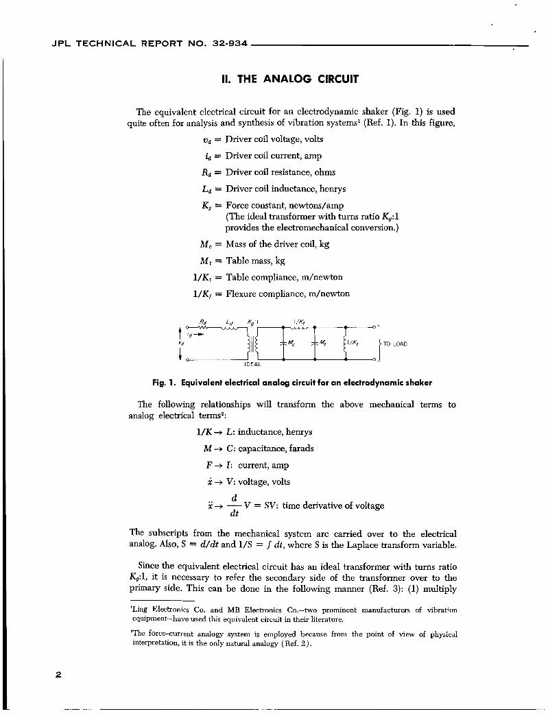
The equivalent electrical circuit for an electrodynamic shaker (Fig. 1) is used quite often for analysis and synthesis of vibration systems' (Ref. 1). In this figure,
od = Driver coil voltage, volts
id = Driver coil current, amp
Rd = Driver coil resistance, ohms
La = Driver coil inductance, henrys
K g = Force constant, newtons/amp (The ideal transformer with turns ratio K,:l provides the electromechanical conversion.)
M, = Mass of the driver coil, kg
M t = Table mass, kg
l /Kt = Table compliance, m/newton
l / K f = Flexure compliance, m/newton
Fig. 1. Equivalent electrical analog circuit for an electrodynamic shaker
The following relationships will transform the above mechanical terms to analog electrical terms2:
1/K + L: inductance, henrys
M 3 C: capacitance, farads
F + I : current, amp
X + V: voltage, volts
2 3 - V = SV: time derivative of voltage a at
The subscripts from the mechanical system are carried over to the electrical analog. Also, S = d/dt and 1/S = J dt, where S is the Laplace transform variable.
Since the equivalent electrical circuit has an ideal transformer with turns ratio KOA, it is necessary to refer the secondary side of the transformer over to the primary side. This can be done in the following manner (Ref. 3): (1) multiply
'Ling Electronics Co. and MB Electronics Co.--two prominent manufacturers of vibrat;on equipment-have used this equivalent circuit in their literature.
'The force-current analogy system is employed because from the point of view of physical interpretation, it is the only natural analogy (Ref. 2 ) .
2
JPL TECHNICAL REPORT NO. 32-934
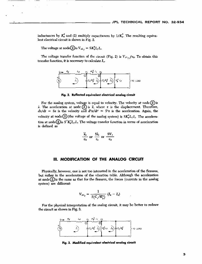
inductances by K: and (2) multiply capacitances by lent electrical circuit is shown in Fig. 2.
The resulting equiva-
The voltage at node@ v , ~ , = S K ~ L , I , .
The vdtage transfer function of the circuit (Fig. 2) is Vzr,f / U d . To obtain this transfer function, it is necessary to calculate Is.
fig. 2. R e f l e c t e d equivalent electrical analog circuit
For the analog system, volta e is equal to velocity. The velocity at node @is i. The acceleration at node Q is 2, where x is the displacement. Therefore, dx/& = Sx is the velocity and d2r/dt2 = S2x is the acceleration. Again, the velocity at node@(the voltage of the analog system) is S ~ I , , Z ~ . The accelera- tion at node@ S2K;LfI3 . The voltage transfer function in terms of acceleration is defined as
.. x, si, sv,
or - or - - o d Vd u d
111. MODIFICATION OF THE ANALOG CIRCUIT
Physically, however, one is not too interested in the acceleration of the flexures, but rather in the acceleration of the vibration table. Although the acceleration at n o d e o i s the same as that for the flexures, the forces (currents in the analog system) are different:
For the physical interpretation of the analog circuit, it may be better to redraw the circuit as shown in Fig. 3.
Fig. 3. Modified equivalent electrical analog circuit
3
JPL TECHNICAL REPORT NO. 32-934
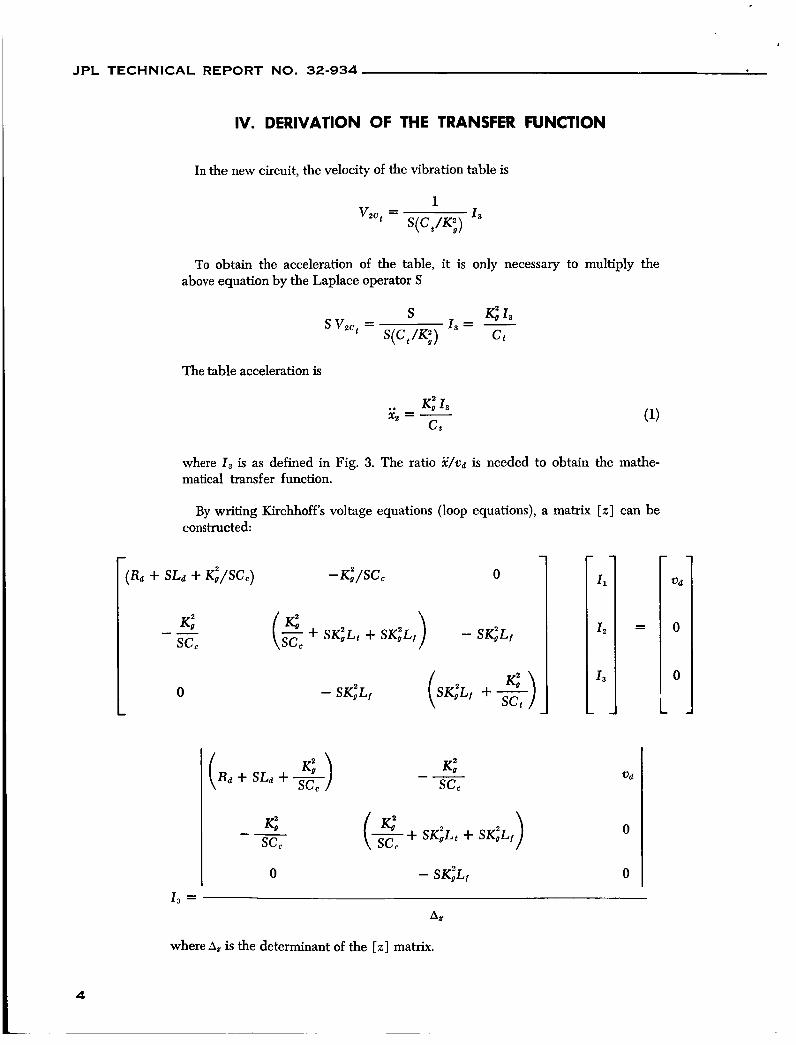
IV. DERIVATION OF THE TRANSFER FUNCTION
In the new circuit, the velocity of the vibration table is
1 S( C , /K' , )
vzc, =
To obtain the acceleration of the table, it is only necessary -3 multiply the above equation by the Laplace operator S
The table acceleration is
.. K," 1 3 xz = -
Ct
where I , is as defined in Fig. 3. The ratio x/u, is needed to obtain the mathe- matical transfer function.
By writing Kirchhoff's voltage equations (loop equations), a matrix [ z ] can be constructed:
(Rd + S L d + K i / S C c ) - K i / S C , 0
0
K: -- see
0 - S K ~ L ~ I I, =
A Z
ud
0
0
where Az is the determinant of the [ z ] matrix.
4
J P L TECHNICAL REPORT NO. 32-934
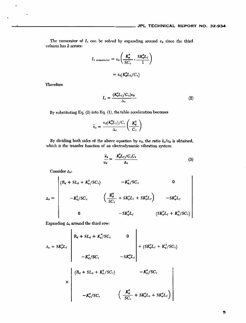
The numerator of I , can be solved by expanding around ud since the third column has 2 zeroes:
Therefore
By substituting Eq. (2) into Eq. (l), the table acceleration becomes
By dividing both sides of the above equation by Ud, the ratio xJva is obtained, which is the transfer function of an electrodynamic vibration system:
Consider Az:
0
0 -sGLf (SKiLf + Ki/SCt) I Expanding Az around the third row:
Az = SKiLf
& + SLd + K:/SCc 0
+ ( S K ; L ~ + K,'/sc,)
- Ki/SCc -SK;Lj
I ( R d + SLa + Ki/SC,) - Ki/SCc I
- K;/SCc ( & + SK;Lt + SKiLf)
5
JPL TECHNICAL REPORT NO. 32-934 *-
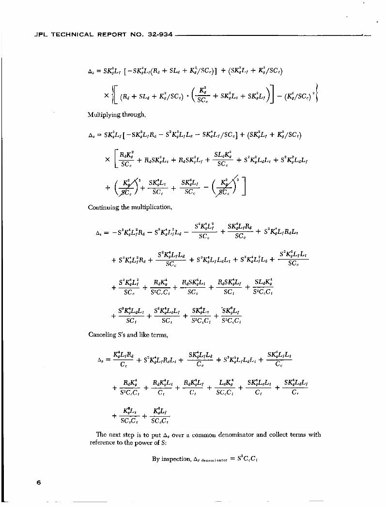
Multiplying through,
Continuing the multiplication,
Canceling S's and like terms,
%Lt @ f +-+- sccct SCcCt
The next step is to put A, over a common denominator and collect terms with reference to the power of S:
By inspection, A, denominator = SZCcCt
6
JPL TECHNICAL REPORT NO. 32-934
+ S3eL fL tCt + s3K;LaLtcc + S3GLdLfCC]
+ [S2Ct.FS'Lf& + SZR&LtCc + S2%K,'LfCc]
+ [SL& + SKiL, + SKiL,] + %K:
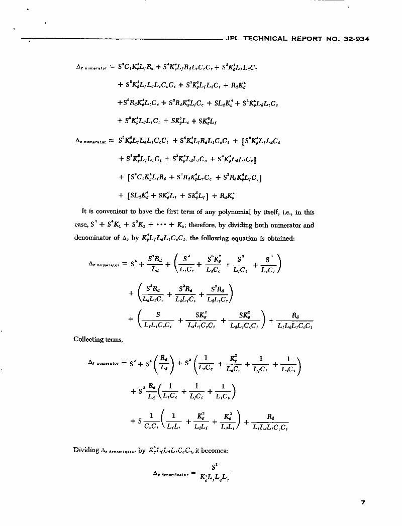
It is convenient to have the first term of any polynomial by itself, i.e., in this
case, S + S'K, + S3K, + + K,; therefore, by dividing both numerator and
denominator of Az by K;LfLdLfCCCt, the following equation is obtained:
~z numerator = S' + - s3 s3< +-+-) s3 s3 LtCC Lac, LfCt LtCt
Collecting terms,
numerator = s 5 + s 4 (s) + s3 (L,c, 1 + - e Lace LfCt +E)
1 1 +-
+ S 2 % -(- 1 +-+-) 1 1 La LtCC LfCt LtCt
7
JPL TECHNICAL REPORT NO. 32-934
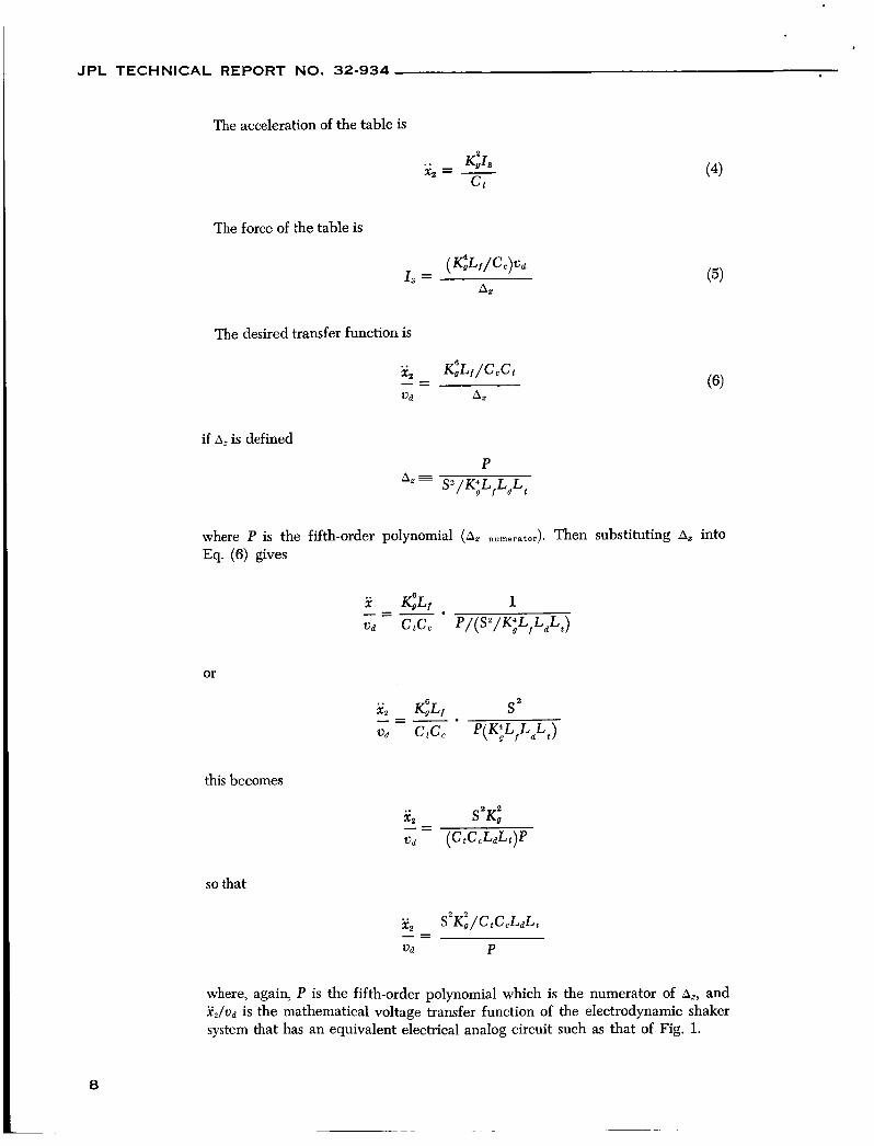
The acceleration of the table is
.. xz = - ct
The force of the table is
The desired transfer function is
(4)
if A, is defined
P A, = S2/K;L,LdLt
where P is the fifth-order polynomial (A, Eq. (6) gives
Then substituting A2 into
or
this becomes
so that
where, again, P is the fifth-order polynomial which is the numerator of A,, and x 2 / t ) d is the mathematical voltage transfer function of the electrodynamic shaker system that has an equivalent electrical analog circuit such as that of Fig. 1.
JPL TECHNICAL REPORT NO. 32-934
Value
8.16 X l@
6.30 X lo' 1.815
6.120
1.2 x lo4
3.0
190.0
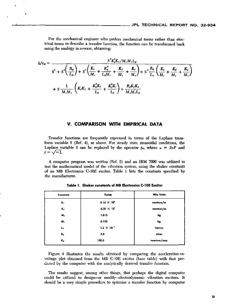
For the mechanical engineer who prefers mechanical terms rather than elec- trical terms to describe a transfer function, the function can be transformed back using the analogy in reverse, obtaining:
Mks Units
newtunr/m
n e h n r / m
kg
kg
henrys
ohms
newtonr/amp
V. COMPARISON WITH EMPIRICAL DATA
Transfer functions are frequently expressed in terms of the Laplace trans- form variable S (Ref. 4), as above. For steady state sinusoidal conditions, the Laplace variable S can be replaced by the operator it., where o = 2zF and j=m.
A computer program was written (Ref. 5) and an IBM 7090 was utilized to test the mathematical model of the vibration system, using the shaker constants of an MB Electronics C-1OE exciter. Table 1 lists the constants specified by the manufacturer.
Table 1. Shaker constants of MB Electronics C l O E Exciter
Constant
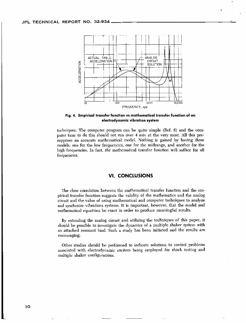
Figure 4 illustrates the results obtained by comparing the acceleration-vs- voltage plot obtained from the MB C-1OE exciter (bare table) with that pre- dicied by h e computer with the anaiyi-icaiiy derived transfer function.
The results suggest, among other things, that perhaps the digital computer could be utilized to design-or modify-electrodynamic vibration exciters. It should be a very simple procedure to optimize a transfer function by computer
9
JPL TECHNICAL REPORT NO. 32-934
FREQUENCY, cps
Fig. 4. Empirical transfer function vs mathematical transfer function of an electrodynamic vibration system
techniques. The computer program can be quite simple (Ref. 6 ) and the com- puter time to do this should not run over 4 min at the very most. All this pre- supposes an accurate mathematical model. Nothing is gained by having three models: one for the low frequencies, one for the midrange, and another for the high frequencies. In fact, the mathematical transfer function will suffice for all frequencies.
VI. CONCLUSIONS
The close correlation between the mathematical transfer function and the em- pirical transfer function suggests the validity of the mathematics and the analog circuit and the value of using mathematical and computer techniques to analyze and synthesize vibrations systems. It is important, however, that the model and mathematical equations be exact in order to produce meaningful results.
By extending the analog circuit and utilizing the techniques of this paper, it should be possible to investigate the dynamics of a multiple shaker system with an attached resonant load. Such a study has been initiated and the results are encouraging.
Other studies should be performed to indicate solutions to control problems associated with electrodynamic exciters being employed for shock testing and multiple shaker configurations.
1 0
. .,
J P L TECHNICAL REPORT NO. 32-934 .
1. Usher, T., ”Simplification of Random Vibration,” Test Engineering, September 1960.
2. Firestone, F. A., ”The Mobility of Computing the Vibration of Linear Mechanical and Acoustical Systems: Mechanical-Electrical Avalogies,” lourno! of Applied Physics, Volume 9, June 1938, pp. 373-387.
3. Cheng, D. K., Analysis of linear Systems, Addison-Wesley Publishing Company, Inc., 1961, p. 58.
4. D’Azzo, j. j. and C. ii. iioupis, Feedback Coniroi Sysiem Anaiysis and Synihesis, McGraw-Hill Book Co., 1960, p. 94.
5. Hofmeister, L. D., private communication.
6. McCracken, Daniel D., A Guide to Fortran IV Progrornming, John Wiley 8 Sons, Inc., 1965, p. 46.
1 1
JET PROPULSION LABORATORY California Institute of Technology 1800 Oak Grove Drive, Pasadena, California 91103
July 1, 1966
Recipients of J e t Propulsion Laboratory TEfChrriCd Repert No, 32-934
SUBJECT: Erra ta
Gentlemen:
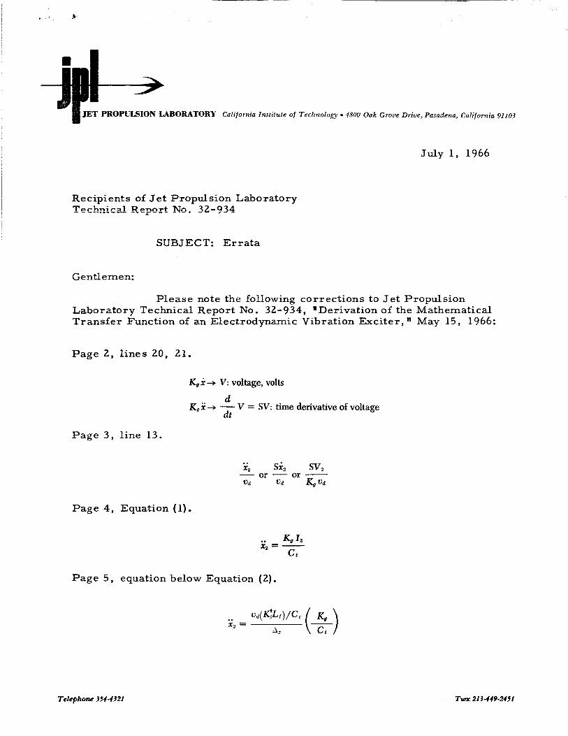
Please note the following corrections to J e t Propulsion Laboratory Technical Report No. 32-934, "Derivation of the Mathematical Transfer Function of an Electrodynamic Vibration Exciter, " May 15, 1966:
Page 2 , lines 20, 21.
r<, x + V: voltage, volts
K, x + - V = SV: time derivative of voltage d at
Page 3, line 13.
Page 4, Equation (1).
.. GI3 x, = -
Ct
Page 5, equation below Equation (2).
Telephone 354-4321 TWX 213449-2151
. - c
JET PROPULSION LABORATORY California Instilute of Technology 4800 Oak Grose Drive. Pamdenrr 3, C.il;joriiiLi
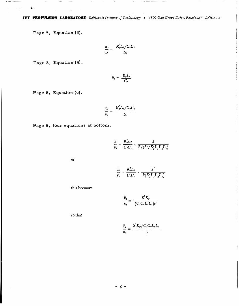
Page 5, Equation (3) . I I
Page 8, Equation (4).
Page 8, Equation ( 6 ) .
Page 8 , four equations at bottom.
or
this becomes
so that
- 2 -
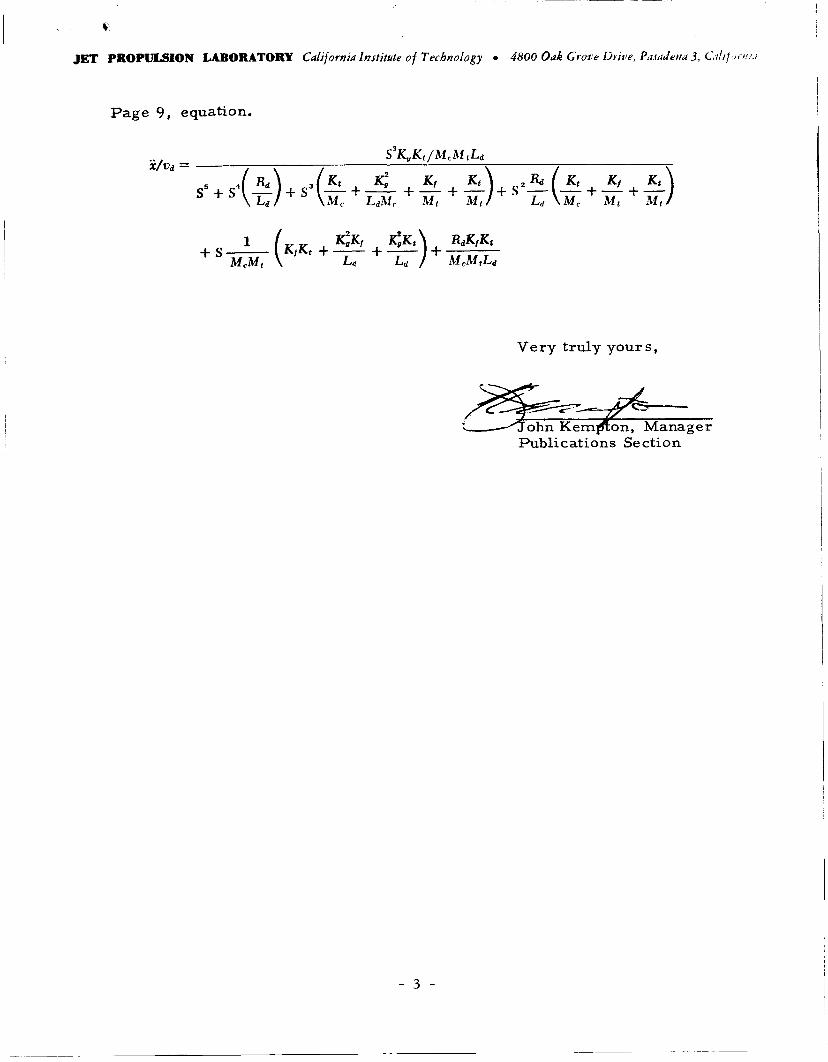
Page 9 , equation.
S'K, K, 1 M, A i , La
Very truly yours,
/zJ&r.r.$-$. - ohnKem on, Manager
Publications Section
- 3 -