Embed Size (px)
Citation preview

9/28/00
CRITICAL RADIO SYSTEMS
SCHEDULEB
EDACS Verification Test
Procedures
STATE OF FLORIDA Joint Task ForceDepartment of Management Services
Com-Net Ericsson Critical Radio Systems Inc. Systems Integration

Service and Access AgreeI(~)for Statewide Radio Communications systenC~=) State of Fllorida - Dep8hment of Management Services
Table of Contents
September·2000
1. CUSTOMER APPROV AL ...... : .................•.... , ...................................•......•.........................•.................................•................. 5 2. SYSTEM ACCEPTANCE ... : ..................................•........................ ~ ...•....••..................•.......................................•................. 6 3. PROVOICE EDACS TRUNKED SYSTEM VISUAL INSPECI10N ....................•...............•.............................................. 7 . 3.1 Visual Inspection ................................................•............................................................................................•......••......... 7
4. GROUNDn-lG INSPECTION ............................................................•........•............•.....................•............................•...•....... 8· 4.1 Grounding. Validation ........................................•.... ~ ....................••.....................••.....•.•.............................................•....... 8
5. RADIO FEATURE SET .......... : ..................................................................................•. ; .......................................................... 9 5.1 Setup .................................................................................................................................................................................. 9 5.2 System All Call ..................................................................................................................... ~ .......................................... 10 5.3 Group Call (Agency, Fleet, Subfleet) ............................................................ : .................. ; .............................................. 11 5.4 Emergency Group Call .................................................................................................................................................... 13 5.5 Individual Call ........................................................... ~ ..................................................................................................... 14 5.6 Transmit Grant Tone .............................................. " ......................................................................................................... 15 5.7 Out·OfRange Tone.On PIT ........................ : ................................................................................................................... 16 5.8 Group Scan ...................................................................................................................................................................... 17 5.9 Transmit Busy Lockout ...... ; ................................................. ~ ................................ , ......................................................... 18 5.10 Call Queue. Declaration Alert ......................................................................................................................................... 19 5.11 Emergency Declaration And Clear •...................•.... ~ .......•..•........•.. ~ ............................................................................... 21
6. PROVOICE EDACS TRUNKED SYSTEM FEATURE.SET ......... ~ .................................................................................... 22 6.1 Continuous Control Channel Update .......................................................................... , .................................................... 22 6~2 TransmissionlMessage Trunking (GID) ........................................................................................................ : ................. 23 63 Convert To Callee ............................................................................................................................................................ 24 6.4 Call Queuing ................................................................ " ... , ................................................................................................ 25 6.5 Call Priority For Gills ............................................ ~ ........................................................................................................ 26 6.6 Emergency Call Priority For GIDs ..................................................................................................................... , ............ 27 6.7 Call GID V aIidation ................ ~ ......................................................................................................................................... 28
7. TIER 2 (Intra WC) FEATURE SET ..................................................................................................................................... 29 7.1 Setup ............................................. ~ ...................................................... : ........................................................................... 29 7.2 Group Call (Agency, Fleet, Subfleet) .............................................................................................................................. 30 7.3 Emergency Group Call .................................................................................................................................................... 31 7.4 Individual Call ................................................................................................................................................................. 32 7.5 Confirmed Call ..................... ; .......................................................................................................................................... 33 7.6 Unconfinned Call (Multisite Late-Enter) ......................................................................................................................... 34 7.7 Multi-site Routing (for Multi-site Logout) ...................................................................................................................... 35
8. TIER 3 (Inter WC) FEATURE SET ......................................................................................... " ........................................... 37 8.1 Setup ................................................ ~ ............................................................................................................................... 37
. 8,2 Group Call (Agency, Fleet, Subfleet) ............................................................................................................................... 38 8.3 Emergency Group Call •....• ; ............................................................................................................. ~ ...........• ~ .................. 39 8.4 Individual Call ................................................................................................................................................................. 40 8.5 Confirmed Call.; ...................... , ....................................................................................................................................... 41 8.6 Unconfinned Call (Multinode Late Enter) ....................................................................................................................... 42 8.7 Login Across Nodes ......................................................................................................................................... , ............... 43 8.8 Multi-site Routing (for Multi-site Logout) ............ , ......................................................................................................... 44
9. POWER INTERRUPTION .............................................................................................................................. ~ .................... 46 9.1 P·o~er Backup 1 UPS Verification ................................................................................................................................... 46
10. SWULCAST ALARM SySTEM .............................................................................................. ; ........................................ 47 10.1 Software Setup ............................................................................................................................................................... 47 10.2 Screen Configuration ............. : ............................................................ ~ .......................................................................... 48 10.3 Status Update ................................................................................................................................................................. 49 lOA User Defined Alarms ..................................................................................................................................................... 50.
11. SIMULCAST BYPASS OPERATION ............................ , ........................................... : ............................. : ......................... 51 11.1 Setup ............................................................................................................................................................................... 51
criTiCAl IJDIO lrlr£.~
Company Proprietary and Confuienti.aI
·9128/00 . ScheduleB
Page 2
Service and Access Ag:reemt~r Statewide Radio Commtiiucations System (j '" /' ',/
State of Florida - DepartIDiumt of Management Services September 2000
11.2 Site OFF - Final Configuration ...................................................................................................................................... 52 1 1'.3 Site ON - Final Configuration ..........................................................•..................................•.....................•......•............. 53 11.4 Control Point Trunking Reset Control ........................................................................................................................... 5S
12. PROVOICE EDACS VOTER ..........•...............................•...................................•.........................................•.................... 57 12.1 Setup ...................... ~ ....................................................................................................................................................... 57
'12.2 Digital Voter Functional Tests ....................................••....•...............................................................•.....................•...... 58 12.3 Analog Voter Functional Tests ............................................•.......................................................................................•. 59
13. CENTRALIZED TELEPHONE IN1"ER.CONNECT CALLS ............................................................................................. 60 13.1 Radio Originated Interconnect Call ............................................................................................................................... 60 13.2 Telephone Originated Interconnect Call to Radio ........................................ ; ................................................................. 62 13.3 Telephone Originated Interconnect Call to Group ......................................................................................................... 63
14. LOCAL DISPATCH FEATURE SET (C3'MAESmO) .................................................•.................................................. ,64, 14.1 Transmitting With ~C Or Headset .............................................................................................................................. 64
14.1.1 Group Call .............................................................................................................................................................. 64 14.1.2 Individual Call ............................•............................ ; .............................................................................................. 65 14.1.3 Alert Tones .............................................................. ; .............................................................................................. 65 14;1.4 Digital Dispatch ...................................................................................................................................................... 66
14.2 Receiving Galls ........................................................... ; .................................................................................................. 67 14.2.1 Group Call ......................................................................... ; ..................... ; ...................................... ~ ....................... 67 14.2.2 Individual Call ....................................................................................................................................................... 67 14.2.3 Call History ............................................................................................................................................................. 68 14.2.4 Digital Dispatch~." ........................................................................................................................................... ~ ....... 68
14.3 Emergency Call ............... ~ ...................... , ................•.......•.....................•......................................................... : ............... 70 14.4 Agency Broadcast .......................................... ~ ............................................................................................................... 71 14.5 Patch ......................... : ............................... : ... ~ ................................................................................................................ 72 14.6 Simulselect .................................................................................... , .......................................... : ...................................... 74 14.7 Console Pre-Empt ................................................... , ...................................................................................................... 75
14.7.1 Clear Voice Dispatch .............................................................................................................................................. 75 14.7.2 Digital Dispatch ...................................................................................................................................................... 75
14.8 Console to Console Interaction ...................................................................................................................... : ............... 77 14.8.1' Console Intercom ....................................................................................... ' ....... : ..................................................... 77 14.8.2 Console Crossmute ........................................................................................................... : ..................................... 77
14.9 Supervisor Console ........................................................................................................... : ............................................ 79 14.9.1 Priority Override (pre-empt) ................................ , ......................................................................... ~ ......................... 79 14.9.2 Console EnableIDisable ............................... ~.; ........................................................................................................ 79 1 ~.9.3 Unprogrammed Emergency ............................................................................................. ~ ...................................... 80
14.10 Conventional Interface (CI) .................. ~ ...................................................................................................................... 81 14.11 Telco Interconnect (Call Director) ............................................................................................................................... 82
14.11.1 Answering a Call .................................................................................................................................................. 82 14.11.2 Patching a Call ...................................................................................................................................................... 83
14.12 Logging Recorder ...................................................... ~ ................................................................................................. 85 15. PROSOUND ROAMING .................................................................................................................................................... 86 , 15.1 Adjacency Broadcast ................................................................................................................................... , .................. 87
15.2 Roaming ......................................................................................................................................................................... 88 16. COMMUNICATIONS SYSTEMS DIRECTOR (CSD) FEATURE SET .......................................................................... 89
16.1 Setup .............................................................................................................................................................................. 89 16.2 Site Reconfiguration ...................................................................................................................................................... 91 16.3 Communications Systems Director Communication ....................................... ~ ................. ~ ........................................... 92 16.4 Communications Systems Director Reports .................................................................................................................. 93 16.5 System Mainte1¥lllce .............. ; ....................................................................................................................................... 94 16.6 Activity Download ......................................................................................................................................................... 95-16.7 Alann Control Display ................................................................................................................................................... 96 16.8 Relay Trigger Definitions ............................... ~ .............................................................................................................. 97 16.9 Unit Enabl~isable ........................................................................ : .............................................................................. 98
~ ,-"'"" EriLsson "~~1!!~_.~_,._ ... ___ .. ~.--
CllTftAl RADIO sunlJ!
Company Proprietiuy and Confuiential
9128/00 ScheduleR
PageS

Service and Access ~mt for Statewide Radio Communications sys{~ State of Fllonda - Department of M21I12eement Services
September 2000
16.10 Activity Detail Report .................................................................................................................................................. 99 16.11 Activity Summary Report .......•.. ""'" ...............................................................................................•......•...•...........•.. 100 16.12 Alarm Report .............................................................................................................................................................. 101 16.13 Channel Statistics Report ........................................................................................................................................... 102 16.14 Site Statistics Report ..................................•.............•.......................................•................•................................... ~ .... 103 16.15 Dynamic Regroup .....................................•...................................................................................................•............. 104
17. RF COVERAGE .............................................................................................................................................. : ....•......•..... 107 17~1 Description afTest Method ................................................................................................................. ~ ................•.•.... l 07 17 .2 Test Equipment and. Preparation .................................................................................................................................. 108 17.3 Test Location Planning ...............................•.•...................•.......•.....•......................................................•......•.............. 108 17.4 Gradirig ofT est Locations ......................•...•.............••. : ...•............................•.............................................................. 109 17.s Data Analysis and Acceptance ................•...............................•................................•................................................... 110 17.6 Maritime Distance Testing ......................................................•...........................•........•.................................•....... : ..... ·111 17.7 Aircraft Coverage Testing ......................................................................................................................... , ............. : .... 112 . 17.8 Results Presentation .............•...........................................•..................................••...•..........•........................................ 112
18. Non-Intexference Verification ...... ~ .. ~ ............................................. : ......••...................•.............•.......................................... 114 19. Other Acceptance Tests ...................•.........•...•.........................••..•...•.....•....•.•.••..•.•....•.........•... ~ ....•..•.......••...•..•••.......•... 116
.}iWEr. Ericsson .. '.'_._--. CRlil;U naDia surEU'
. Company p!oprietary and ConfuientiaI
9128/00 ScbeduleB
Page 4

Service and Access A~ht for Statewide Radio Communications syst[) State of Florida - Depaiiment of Management Services
1. CUSTOMER APPROVAL
September 2000
This PROVOICE EDACSAcceptance Test Procedure has been read and approved for use as the system . acceptanc~ test.
Customer Representative
Signature
Printed name and title
~ fl"ri- Ertcsson .. ~--~----..... -----~ BIT I C & La, a I· a I v S r E • Z
. Company Proprietary and Confidential
Com-Net Ericsson
Signature
Printed name and title
9128/00 ScheduleD
PageS

Service and AcCess Agreen~for Statewide Radio Communications System() State of1Florida - Delpa'rtinelilt of Management Sernces ...
2. SYSTEM ACCEPTANCE
This PROVOICE EDACSAcceptance Test Procedure has been successfu/iy completed.
Customer Representative
Signature
Printed name and title
Date
~ I,,"" Ertc.sson IJL~]!.~~ ___ ~_.NN" __
tlliaH RADIO ITSfEIU
Company Proprietmy and ConfuientiaJ
Com-Net Ericsson
Signature
Printed name and title
Date
September 2000
9128/00 ScheduleR
Page 6

Service and Access Agree(--"~ for Statewide Radio Communications Systet( ''') State of FRorida - DepS:lri:fuent of MalilagementSemce5'- /
September 2000
3. PROVO~CE EDACS TRUNKED SYSTEM VISUAL INSPECTION
Acceptance Test Procedure Version: Rev.D Jan 11998 Last Modification Date:
3.1 Visual Inspection
Setup
Execution
Results
Tester.
Comments:
Prior to the actual acceptance test, a physical inspection of the PROVOICE EDACSequipment must be performed. All equipment locations must be inspected. Any discrepancy, which affects operator safety, must be corrected before the remaining tests are performed.
1. Verify the area is clean and that all cabinets and racks are both clear of debris and clean.
2. Verify all equipment racks are spaced per the drawings, secured and grounded.
3. Verify all rack cables are dressed, secured and correctly marked.
4. Verify all nameplates and labels are in place.
5. Verify all protective foam, tape, aryd packing material has been removed.
6. Verify all punchblocks are labeled.
(Pass/Fail)
Date:
~ I ....... Erh:sson IJL~~~ ___ ... ___ .. _
Company Proprietary and Confuiential
9128/00 ~ Schedule B
Page 7

Service and Access Agree:n~~)r Statewide Radio Commmrications System r) State of Florida - Departwellllt of Mallllagemellllt Services. '... /
September 2000
4. GROUNDING INSPECTION
Acceptance Test Procedure Version: Rev.C lan 1 1998 Last Modification Date:
4.1 Grounding Validation
Setup
Execution
Results
Tester:
Comments:
For detailed information on grounding validation, refer to the grounding LSI and speCification.
1. Verify all grounds measure less than 5 ohms to earth.
2. Verify all electrical outlets are grounded with one ground per circuit.
3. Verify all electrical bonding preserves integrity to equipment ground (Isolated ground). .
4. Verify the halo ground is connected to site ground at each comer'of the c6mmunication shelter. (If this is not possible, provide justification in the comment section.)
5. Verify common point for halo ground~ and tower grounds to RF cable entry panel.
Company Proprietary and ConfuIential
(Pass/Fail)
Date:
CRiTICAL RADIO InTrl:
9128/00 ScheduleS
PageS

Service and Access Agree(;t for Statewide Radio Communications Syste(} , State of Florida - Department of Management Services '
5. RADIO FEATURE SET
Acceptance Test Procedure Version: Last Modification Date:
5.1 Setup
Rev.B Jan 1 1998
This setup applies to the tests contained in this section.
September 2000
Three radios are required, programmed as follows: (Utilize test or customer data base groups A, B, C& 0 as speCified here)
Radio 1: System Supervisor unit; with System All Call capability and with Agency, Fleet, and Subfleet GIDs programmed.
Radio 2: (Group A) - GID for Agency 1, Fleet 1, Subfieet 1. (Group 8) - GID for Agency 1, Fleet 1, Subfleet 2. .
Radio 3: (Group A) - GID for Agency 1, Fleet 1, Subfleet 1. (Group C) - GID for Agency 1 , Fleet 2, Subfleet 1. (Group D) - GID for Agency 2, Fleet 1, Subfleet 1.
"
Note: Additional radios are required for Call Queue Declaration Alert test.
~ H..-rY- Ertcsson 1JL~~ ___ ~_.l _ ... _______ _
Company Proprietary and Confidential
9/28/00 ScheduleB
Page 9

Service and A~ Agreem(;or Statewide Radio Communications System(} State of Florida - Deparln:ieJIllt of Management Services ...
5.2 System All Call
Setup
September 2000,
Set radio 1 to System All Call, radio 2 to (Group A) and radio 3 to (Group D).
Execution
Results
Tester:
Comments:
1 . Place the System All Call from radio 1.
2. Audio should be heard at radios 2 and 3. The LID of radio 1 should be seen at radios 2 and 3.
3. Set radio 2 to (Group 8) and radio 3 to (Group C).
4. Place the System All Call from radio 1.
5. Audio should be heard at radios 2 and 3.
6. If applicable, repeat the previous steps for digital voice.
Company Proprietary and Confidential
(Pass/Fail)
Date:
ClJ1JnL I4DJD SUTEI:
9128/00 Schedule B
Page 1~

.:,',":""
Service and Access Agreen{~for Statewide Radio Communications System( ') '-. _/ ~" -- September 2000
State of Fllorida - Department of Management Services ..
5.3 ~roup Call (Agency, Fleet, Subfleet)
Setup
Execution
Set radios 1, 2, & 3 to (Group A) per ~ustomer or Test Group structure.
Subfleet Call Tests
1. PIT radio 1 and talk. The transmit (TX) indicators should tum on at radio 1 .
2. Audio should be heard in radios 2 & 3. The LID of radio 1 should be seen at radios 2 and 3.
3. Set radio 3 to (GroupS). PIT on radio 1 and talk. The transmit (TX) indicators should tum on at radio 1.
4. Audio should be heard in radio 2 only~The L1D'of radio 1 should be seen at radio 2 only.
Fleet Can Tests
5. Set radios 2 & 3 to (Group A). Set radio 1 to Fleet 1, PTT radio 1, and verify audio 'on radios 2 & 3.
6. Set radio 3 to.(Group C). PTT radio 1 on Fleet 1, and verify audio on radio 2 only.
. 7. Set radio 1 to Fleet 2, PTT radio 1. and verify audio on radio 3 only.
Agency Call Tests
8. Set radios 2 & 3 to (Group A). Set radio 1 to Agency 1. Key radio 1 and verify audio On radios 2 and 3.
9. Set radio 3 to (Group D). PIT radio 1 on Agency 1, and verify audio on radio 2 only.
10. Set radio 1 to Agency 2, PIT radio 1, and verify audio on radio 3 only.
11. If applicable, repeat the previous steps for digital voice.
~qjrnorJ tl·ITltlL .&010 SISTEMS
Company Proprietary and Confuiential
9128/00 ScheduleB
Page 11

Service and Access A~f)t for Statewide Radio Communications Syst~) State of Florida - Department of Mallllagement Services
Results
Tester:
.. Comments:
..
~ I,,"" Ericsson .... ~--~-, -~--~ .... _ .. _-talrl"'L RADIO SYSTEM:.
Company Proprietllry and Confulential
(Passlfai8)
Date:
September 2000
9128100 ScheduleR
Page 12

i'.
Service and Access Agre()t for Statewide Radio Co~unications Syst~) Stite of Florida - Department of Management Services '
September 2000
5.4 Emergency Group Call
Setup
Execution
Results
Tester:
Comments:
Program three radios with the same emergency home group. Set the supervisor radio (radio 1) and radio 2 to the home group. Set radio 3 to a different group (not home group).
1. Press the Emergency call button on radio 3.
2. Verify that the radio sounds the emergency declaration torie and that it has reverted to the home group. .
3. Clear the emergency with the Supervisor radio. Verify the emergency clears in the radios.
4. If applicable, repeat the previous steps for digital voice. .
Company Proprietary and Confuiential
(Pass/Fail)
Date:
9~8/00
ScheduleB Page 13

Service and A~ AgreeI(jfor Statewide Radio Comm~cations System() State ofFionda- Depsltl!.JIJlelIlt of Management Services ...
September 2000
5.5 Individual Call
Setup
Execution
Results
Tester:
Comments:
Set radios 1, 2, & 3 to (Group A) per Customer or Test Group structure.
1. Using the radio 1, selectthe pre-stored LID of radio 2 or enter the radio 2 LID directly from the keypad, and PIT radio 1.
2. Verify that radio 2 receives the call and displays the LID of radio 1. Verify that radio 3 remains idle.
3. Release the PIT on radio 1 and immediately PIT on radio 2.
4. Verify that radio 1 receives the call and displays the LID of radio 2. Verify( radio 3 remains idle.
5. Using the radio 1, select the pre-stored LID of radio 3 or enter the radio 3 LID directly from the keypad, and PIT radio 1.
-6. Verify that radio 3 receives the call and displays the LID of radio 1. Verify
that radio 2 remains idle.
7. Release the PIT on radio 1 and immediately PIT on radio 3.
8. Verify that radio 1 receives the call and displays the LID of radio 3. Verify radio 2 remains idle. , .
9. If applicable, repeat the previous steps for digital voice.
..
Company Proprietary and . Confuiential
. "" .. "-". '.". .
(Pass/Fail)
Date:
ell T i C.l L i, 0 lOS T S TEll S
9128/00 ScheduleB
Page 14

Service and Access Agreem(;for Statewide Radio Communications System(} State of Florida - Department of Management Services .. .. J
5.6 Transmit Grant Tone
Setup One radio with valid LID and valid group on selected system.
September 2000
Grant tone (Ready to Talk tone) enabled in radio personality as applicable for specific radio type being tested.
Execution
. Results
Tester:
Comments:
1. Press PIT button on radio with valid group selected.
2. Verify grant tone is heard at radio when working channel access is· granted.
Note: If the call is queued, the grant tone will be delayed until theca" is assigned a working channel.
(Pass/Fail)
Date:.
~ I ....... Ertcsson ... ~_!_~ __ ~_._ ... _ ........ w._
Company Proprietmy and ConfuIential
·9128/00 ScheduleD
Page 15 CllliCH HOlD SOTEII:

Service and A~ Agreem~ior Statewide Radio Comm~cations System (') State of Flonda - Department of Management ServIces . .
September 2000
5.7 Out Of Range Tone On PIT .:J- Setup
Execution
Results
Tester:
Comments:
One radio with valid LID and valid group on selected system.
System scanning (Wide Area ScanlProSound) disabled in radio personality as necessary for specific radio type being tested.
1. With valid group selected. and radio initially logged into and monitoring the control channel on the selected system, reduce the signal strength reaching the radio by some means (ex. unscrewing and removing the portable radio antenna, or moving further from the site).
2. Verify, that the radio indicates loss of control channel on the display when the re.ceived signal strength 'is sufficiently reduced (Le. out of range of system).
3. Press PTT button on radio, and verify that an out of range tone is heard at radio.
Company Proprietary and Confuiential
(Pass/Fail)
Date:
CRlilCAL I1DI0 $T~I£II$
9128/00 ScheduleR
Page 16 o '

Service and Access Agree{} for Statewide Radio Communications systern State of Florida - Dep~r6n~mt of Management Services' .
September 2000
5.8 Group Scan
Setup
Execution
Results
Tester:
Comments:
Two radios (radio 1, radio 2) each with valid LIDs and two valid groups (group A, group 8) on selected system.
Radio 1 set up with group A and group 8 in the scan list, group A selected. and group scan initially disabled.
1. Place a call from radio 2 on talk group A.
2. Verify the call is received and audio is heard on radio 1.
3. Place a call from radio 2 on talk group B.
4. Verify the call is not received by radio 1.
5. Enable group scan on radio 1.
6. Place another call from radio 2 on talk group B.
7. . Verify that the call is now received and audio is heard on radio 1.
Company Proprietary and Confidential
,
(Pass/Fail)
Date:
tllTICAL RlOIO nHEI:
9128/00 ScheduleD
Page 17
. I
I !

Service and Access AgreemQ':-';or Statewide Radio Co~unications System n . State of Fiorida - DepartllDent of Management Services ....... .
September 2000
5.9 Transmit Busy Lockout
Setup
Execution
Results
Tester:
Comments:
Two radios (radio 1, radio 2) each with valid UDs and sarne valid group on selected system.
Talk group used for test must be set up as transmission trunked. This feature does not apply to message trunked calls.
1. Place a call from radio 1 on selected talk group by pressing and holding. the PIT button.
2. Verify the call.is·received and audio is heard on radio 2.
3. While the call is in progress,- press the PIT button on radio 2.
4. Verify that radio 2 does not transmit over (step on) the call in progress.
(PassIFail)
Date:
~Ertcmn --- --_.
Company ·Proprietary and Confulential
9128/00 ScheduleB
Page 18 ttlTiC.IL I4DIO ;rHESS

Service and Access Agreemf"for Statewide Radio Communications Systemn State of Florida - Depaimlent of Management Sernces-
September 2000
5.10 Call Queue Declaration Alert
Setup
Execution
This test requires two more radios than the number of working channels on the selected system used for test. To minimize the test setup and radio requirements for larger systems, channels may be disabled on the site so only two working channels are operational.
Set up a number of radios equal tothe number of operational working channels on the selected system (radio x, radio y, etc.) each with a different valid talk group selected .
. Set up two additional test radios (radio 1, radio 2) both with the same valid group selected. This talk group must be different than the groups selected by the other test radios.
Ensure that group scan is disabled on all the radios.
1. Busy up an working channels on the system with the first set of radios· . (radio x, radio y, etc.) by pressing and holding the PTT button on each of the radios.
2. With aI/ working channels busied, momentarily press and release the PIT button on test radio 1.
3. Verify that a.CallQueued tone is heard at the radio.
4. Unkey (release PTT button) one of the first set of radios, ex. radiox.
5. Verify that radio 1 is assigned to the freed working channel and the grant tone is heard at the radio, without having to rekey the radio (redepress the PTT button).
6.· Press the PTT button on radio 1 within the autokey time applicable to the radio type (approx. 2 seconds) to keep the assigned channel.
7. Verify that audio from radio 1 is heard at radio 2.
~,'""' Er1Lsson .. ~!!~~':.-.--.--Company Proprietary and
Confuiential 9/28/00
ScbeduleR Page 19 CUT: C II I A a lOS T S TEllS

Service and A~ AgreemC;or Statewide Radio Comm~cations System n State of F10nda - DepartmellDt of Management Sel!'V11ces~-
Resu!ts
Tester:
Comments:
~ I,,"" Ericsson IJL~!!~~~ __
C.AITICll lJDIO SYSTEMS
Company Proprietary and ConfuIentiai
(Pass/Fail)
Date:
September 2000 .
, l'
91l8/00 ScheduleR
Page 20

Service and Access Agree() for Sta:l:eWide Radio Communications Systerl) State of Florida - Dep~eJmt of ~allllagement Semces . -~
. September 2000
5.11 Emergency Declaration And Clear
Setup
Execution
Results
Tester:
Comments:
Two radios (radio 1, radio 2) each with valid LIDs and same valid group (group A) on selected system.
Radio 1 must be emergency capable, and personality programmed as a supervisory radio capable of clearing emergency as necessary for specific radio type being· tested.' .
Radio 2 must be emergency capable, with emergency button enabled In radio personality as necessary for specific radio type being tested.
1. With group A selected on both radios, declare an emergency on radio 2 by . pressing and holding the emergency button for the re,quired radio programmed length of time. .
2. Verify that an emergency declaration indication is displayed at t.he radio.
3. Verify that radio 2 is assigned to a free working channel andthe grant tone is heard at the radio.
4. Press the PTT button on radio 2 within, the autokey time applicable to the radio type to keep the assigned channel.
5. Verify that audio from radio 2 is heard at radio 1.
6. Clear the emergency from radio 1 according to the operator's manual for . the specific radio being used.
7. Verify the emergency is cancelled and the emergency indication is cleared from the radio.
Company Proprietary and ConfuientiaJ
(PassIFail)
Date:
CII.!lCq UDIO IYITEa:
9128100 ScheduleD
Pagel1

Service and Access Ag:reet'~ for Statewide Radio Communications Syste(') State of Florida - Depahfu.elllt of Malllagement Services ',--
6 •. PROVOICE EDACS TRUNKED SYSTEM FEATURE SET
Acceptance Test Procedure Version: Last Modification Date:
Rev;G Sep 11999
6.1 Continuous· Control Channel Update
Setup This test requires two trunked radios and a test group.
Execution 1. Set both radios to the test group.
2. Turn one radio OFF.
September 2000
3. Key one radio and hold. Tum ON the second radio (and set it to the test group if necessary). .
4. Verify that the second radio jOins the call in progress and hears audio from the call in progress. -
5. Unkey the first radio.
Results (PasS/Fail)
Tester: Date:
Comments:
.,,,ffNet Em:sson ---_ .. _-_ .. -
Company Proprietary and ConfuientiaI· .
9/28/00 Schedule B
Page 22 C,ll!iClL IAD.IO InTEII:
:
i

Service and Ac.cess .Agreeril{(')'lr Statewide Radio comm~catioDS System l) State of Flonda - Department of Management Servnces ....
September 2000 .
6.2 Transmission/Message Truriking (GID)
Setup
Execution
Results
Tester:
Comments:
Select two test groups. From the CSD, set test group A for a zero hang time parameter: Set test group B for a 5 second hang time parameter. Have two radios programmed for the test groups.
1. TRANSMISSION TRUNKING: Set both radios for test group .A. Key and unkey radio 1. Verify that the radio 2 responds to the call then immediately goes to idle mode (not busy) when the radio 1 unkeys.
2. MESSAGE TRUNKING: Set both radios for test group B. Key and unkey radio 1. Verify that the radio 2 responds to the call then hangs in the group call (radio busy) for 5 seconds after the radio 1 unkeys.·
3. Repeat the previous step, but during the 5 ·second hang time, verify that the radios can key and get a transmit indicator during the hang time.
(Pass/Fail)
Date:
~_.. ____ . Q_icw_on Company Proprietary and
Confulential 9118/00
ScbeduleB Page 23
I
Service and Access Agreen:('--~Jor Statewide Radio Communications System () State of Florida .:... Department of Mal!Dagement Services "-'
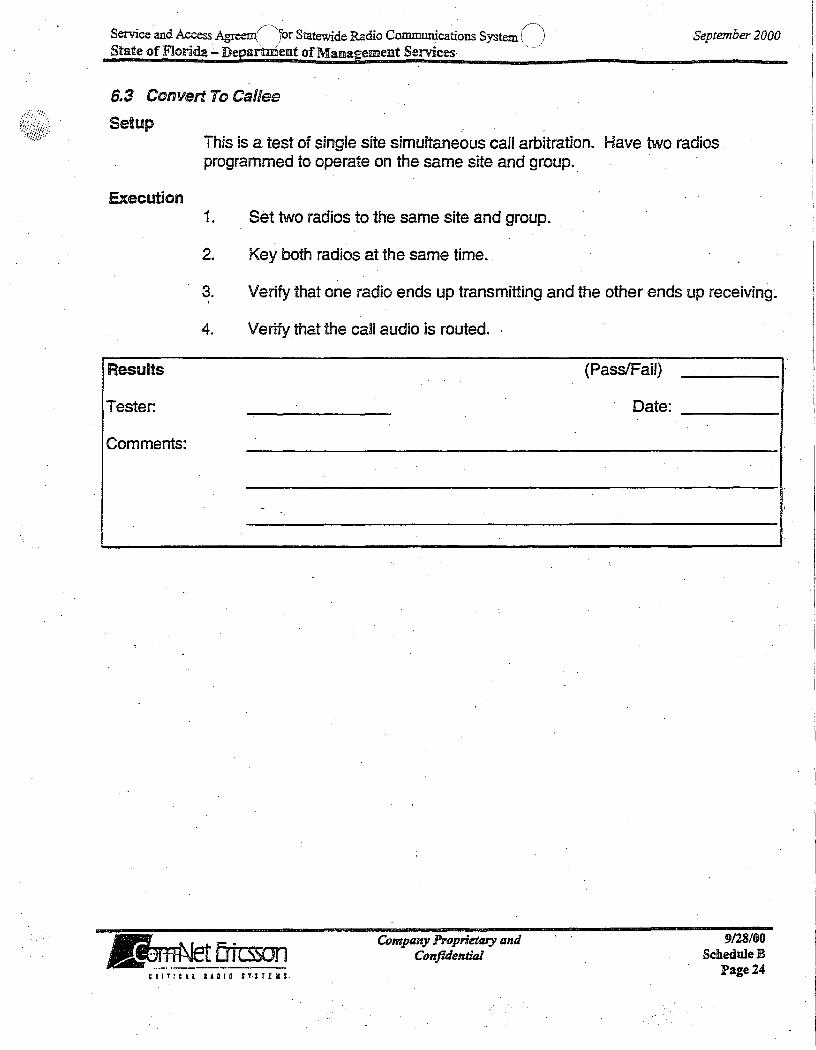
6.3 Convert To Callee
Setup
September 2000
This is a test of single site simultaneous call arbitration. Have two radios programmed to operate on the same site and group.
Execution 1. Set two radios to the same site and group.
2. Key both radios at the same time.
~. Verify that one radio ends up transmitting and the other ends up receiving~
4. Verify that the call audio is routed ..
Results
Tester.
Comments:
-
~ il"ri- Ertt:sson JL~!.1~ ___ . __ _
CRITiCll IADIO Sf.STEIiS
Company Proprietary and Confuiential
(Pass/Fail)
Date:
9128/00 ScheduleB
Page 24

Service and Access Agree;~tfor Statewide Radio Communications Syster:') . . \ ) \' . ./
September 2000 State of Fllonda - Depamnent of Management Services ...
6.4 Call Queuing
Setup
Execution
Results
Tester:
Comments:
This test requires one more. trunked radio than there are working channels at the site. The procedure is presented assuming there . are two working channels (3 channel site). Disable channels (if necessary) until there are 2 working channels at the site. Thus, three (3) radios are required.
1. PTT two radios, each set to different groups, and hold the channels busy. 80th working channels are now occupied.
2. PIT a third radio on a third group and verify that a high pitched queued beep is heard and the radio is flashing busy. Release PIT on one of the first two radios. Verify that the queued radio emits the grant tone, accesses a channel, and the radio now indicates transmit.
(Pass/Fail)
Date·:
,
..
~ I....f- Em:sson IJL~_~~!~_~ ____ ,._ .... _ .
Company Proprietary and Confuiential
9128/00 ScheduleS
Page2S CRITiCAL RAOID n:lEIIS

Service and Aqcess Agreen(jfor Statewide Radio Communications Systen:Cj State of Florida - Department of Management Services . -
September 2000
6.5 Call Priority For GIDs
Setup
Execution
Results
Tester.
Comments:
This test requires two more radios than there are site working channels. . The procedure is presented assuming there are two working channels. Disable channels (if necessary) until there are two working channels on the site. Thus, 4 radios each with a different group are required for this test. At the CSD group database, set up the groups of radios 1, 2 and 3 for voice call priority 3 (medium). Set up the group of radio 4 for priority 6 (highest). Make sure the LlO'voice priority of each of the radios is less than or equal that of the respective GIO voice priority. Save and upload the database.
1. PIT radios 1 and 2 and hold on transmit to busy both working channels.
2. PTT and release radio 3 (medium priOrity entry into the queue):
3. . PTT and release radio 4 (high priority entry into the queue).
4. Unkey radio 1 and verify that radio 4 unqueues and keys.
5. Unkey radio 2 and verify that radio 3 unqueues and keys.
6. Unkey all radios.
;
Company Proprietary and Confuiential
(Pass/Fail)
Date:
e 1.1 T : elL R A D I 0 IT: r EllS
9/28/00 Scheduie B
Page 26

Service and Access Agre()t for Statewide Radio Communications systeC) State of Florida - Department of Managemellllt Sernces
September 2000
6.6 Emergency Call Priority For GIDs
Setup
Execution
Results
Tester:
Comments:
This test requires the same setup as for Call Priority with one of the radios programmed as a Supervisor radio (enabled to clear emergencies).
. 1. PIT radios 1 and 2 and hold on transmit to busy both working channels.
2. PIT and release radio 4 (high priority entry into the queue).
3. Declare an emergency on radio 3 (medium priority entry into the queue but now at Emergency Priority):
4. Unkey radio 1 and verify that radio 3 unqueues and is assigned a channel without having to PIT. (Key the radio within the specified autokey time in order to keep the channel.)
5. Unkey all radios and clear the emergency with the Supervisor radio.
(Pass/Fail)
Date:
~ I.-+- Ertcsson "~I:!!2,~~_ ... _. ___ .
Company Proprietary and Confulential
9128100 ScheduleD
Pagel7 ' .. 1.1 T : C n II 0 I 0 IT: TE II ;

Service and Access Agre(;J.t for Statewide Radio Communications s~ State of Florida - Department of Management Services
6.7 Call GID Validation
Setup
September 2000
Program a radio with a GrD that is not in the GID database. Verify that the GID under test has been invalidated in the database at the test site.
Execution
Results
Tester:
Comments:
1. Key the radio and verify that a call denied tone is heard.
2. Validate the GID in the eSD and upload the database.
3. Key the radio again and verify that a grant tone is heard.
Company Proprietary and Confulentiizi
(Pass/Fail)
Date:
9128/00 ScheduleS
Page2S"

Service and Access Agreex(j for Statewide Radio Communicatio~ SystenC) State of Florida - Department of Management Sernces
September 2000
7. TiER 2 (Intr8 fMC) FEATURE SET
Acceptance Test Procedure Version: Rev. A Sep 11999 Last Modification Date:
7.1 Setup
This setup applies to the tests contained in this section. Three radios are required, programmed as.follows: (Utilize test or customer database groups A and 8 asspecitied here.)
Radio 1:
Radio 2:
Radio 3:
System Supervisor unit: with Agency, Fleet, and Subtleet GIDs programmed on Site 1. (Group A) - GID for Agency 1, Fleet 1, Subtleet 1 on Site 2 (Group 8) - GJD for Agency 1, Fleet 1, Subtleet 2 on Site 2 (Group A) - GID tor Agency 1, Fleet 1, Subtleet 1 on Site 2
GlDs and UDs must be wide area enabled and valid on all sites.
Company Proprietary and Confidential
9128/00.
C,lIIlCIL lADID ns!£Y:
ScheduleB PageZ9

Service and Access Agiedr't for Statewide Radio Communications Systd) \. ,/ '-,--/
September 2000 State oflF1orida-Department·ofManagement Services
7.2 Group Call (Agency, Fleet, Subfleet)
Setup
Execution
Results
Tester:
Comments:
Set radios 1,2, & 3 to (Group A) per Customer or Test Group structure.
Subfleet Call Tests
1. PIT radio 1 and talk. The transmit (TX) indicators should tum on at radio 1.
2. ALJdio should be. heard in radios 2 & 3. The LID of radio 1 should be seen· at radios 2 and 3.
Fleet Call Tests
3. Set radio 2 to (Group 8) & radio 3 to (Group A). Set radio 1 to Reet 1, PTT radio 1 , and verify audio on radios 2 & 3.
Agency Call Tests
4. Set radio 2 to (Group 8) & radio 3 to (Group A). Set radio 1 to Agency 1. Key radio 1 and verify audio on radios 2 and 3.
5. If applicable, repeat previous·steps for digital voice.
(Pass/Fail)
Date: i
~ I~ Ertcsson IJL~~.~.~~ ___ ~_ .... ~ _______ _
_ Company Proprietary and Confidential
9128/00 Sdiedule-B
Page 30 ~IITIC1L RADIO STSTEM:

,.
Service and Access Agree(\ for Statewide Radio Communications Systr') State ofFlorlda - Depa~eillt of Management Services .. -
September 2000
7~3 Emergency Group Call
Setup
Execution
Results
Tester:
Comments: J
Program three radios with the same emergency home group. Set the supervisor radio (radio 1) and radio 2 to the home group. Set radio 3 to a different group (not home group). The radios must remain logged to different sites.
1. Press the Emergency calf button on radio 3.
2. Verify that the radio sounds the emergency declaration tone and that it has reverted t9 the home group. .
3. Clear the emergency With the Supervisor radio. Verify the emergency clears on all of the radios. .
4. If applicable, repeat previous steps for digital voice.
(Pass/Fail)
Date:
~,...w-Ertcsson 1JIJL~2!!_.~ .. ___ ~_. . _____ .
Company Proprietary and ConfuJentiai
9/28/00 ScheduleB
Page 31 CIITICU 14010 ST:rUI:

!\ (\ Service and AcCess Agree.,,~j for Statewide Radio CommuniCations SysteIh _ ) September 2000 State of Florida - Department of Management Services
7.4 Individual Call
Setup
-Execution
Results
Tester:
Comments:
The radios must remain logged to different sites but switched to the same group. Radio 1 to be a system radio with a keypad. Set radios 1, 2, & 3 to (Group A) per Customer or Test Group structure.
1. Using the radio 1, select the pre-stored LID of radio 2 or enter the radio 2 LID directly from the keypad, and PTT radio 1.
2. Verify that radio 2 receives the call and displays the LID of radio 1. Verify that radio 3 remains idle.
3. Release the PIT on radio 1 and immediately PIT.on radio 2.
4. . Verify that radio 1 receives the call and displays the LID of radio 2. Verify radio 3 remains idle.
5. If applicable, repeat previous steps for digital voice.
(PassIFail)
Date:
,
~'~~ - . UI~IU ___ R. _ .. __ R_._
Company Proprietary anti Confuientitzl
9/28/00 Schedul~B
Page 32

,/ ':\ . c·' Service and Access Agreem( ).br Statewide Radio Communications System )\ State of lFIorida - Department of Management Sernces
September 2000
7.5· Confirmed Cali
Setup
Execution
Results
Tester:
Comments:
From the CSD enable Confirm Call on a test group. Ensure that the group is set up for multisite operation between the two sites (Le. confirmed ealJ enabled, wide area enabled, and valid on both sites). Verify that the two sites are Confirm Call enabled at the fMC Manager.
Log the radios to the sites as follows: Radio 1, Site 1 onthe test group A Radio 2, Site 2 on the test group A
Additional radios are required to busy the working channels. If the system is large, it might be necessary to disable channels at the two sites.
1. Key additional radios on Site 1 until there are no working channels available for the test group.
2. Key Radio 2 on Site 2 and verify that the confirmed call is not allowed to proceed until the "Confirmed Cal! Timeout" period has expired. The calf should go through to Site 2, but not to Site 1. Note: The "Confirmed Call Timeout" parameter is set via the GETC personality.
3. Repeat this test, but this time, free up a channel on site 1 before the "Confirmed Call Timeout" period expires. Verify that the call goes through to both Site 1 and Site 2.
4. If applicable, ~epeat previous steps for digital voice.
"
Company Proprietliry lind Confuiential
(Pass/Fail)
Date:
9128/00 .. Schedule B .
Psge33
dA A (,/~ 'd Ra' d' ., r'\) Service an ccess greem Jor StateWl e 10 CommumcatlODS System', " September 2000 State of Florida - Department of Management Services "'
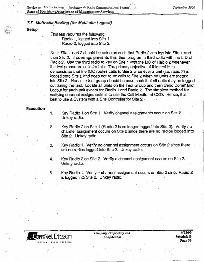
7.7 Multi-site. Routing (for Multi-site Logout)
Setup
Execution
This test requires the following: Radio 1, logged into Site 1. Radio 2, logged ,into Site 2.
Note: Site 1 and 2 should be selected such that Radio 2, can log into Site 1 and then Site 2. If coverage prevents thiS, then program a third radio with the LID of Radio 2. Use the third radio to key on Site 1 with the LID of Radio 2 whenever the test procedure calls for this. The primary objective of this test is to demonstrate that the fMC routes calls to Site 2 whenever a unit (Le. radio 2) is
, logged onto Site 2 and does not route calls to Site 2 when no units are logged into Site 2. Hence, a test group should be used such that all units may be logged out during the test. Locate all units on the Test Group and then Send Command Logout for each 'unit except for Radio 1 and Radio 2. The simplest method for verifying channel assignments is to use the Call Monitor at CSD. Hence, it is best to use a System with a Site Controller for Site 2. ' ,
1. Key Radio 1 on Site 1. Verify' channel assignments occur on Site 2.
2.
Unkey radio.
Key Radio 2 on Site 1 (Radio 2 is no longer logged into Site 2). Verify no channel assignment occurs on Site 2 since there are no radios logged into' Site 2. Unkey radio.
3. Key Radio 1. Verify no channel assignment occurs on Site 2 since there are no radios logged into Site 2. Ur:tkeyradio.
4. Key Radio 2 on Site 2. Verify a channel assignment occurs on Site 2. Unkey radio.
5; Key Radio 1. Verify a channel assignment occurs on Site 2 since Radio 2, is logged into'Site 2. Unkey radio.
~ i-r Ertcsson "~-' --~.-~ .... _._-_._ .. '
Company Proprietary IlIId Confuiential
9128/00 ScheduleB
Page 35 nHIClL IADIO InrEII:

.; ..
Service and Access Agree/lfor Statewide Radio Communicati~ns SystenC') State of Florida - Department of MansgemelIlt Services -,
Results
Tester:
Comments:
. __ ~q.L~MU ctli!~lL IIDID. SYSTEMS
Company Proprietary and Confuiential
(PassIFail)
pate:
September 2000
9128/00 ScheduleR
Page 36

Service and Access Agreenf)for Statewide Radio Communi~ations SystenC~) September 2000 State of Florida - Department of Management Sernces -
8. TiER 3 (Inter IMC) FEATURE SET
Acceptance Test Procedure Version: Rev. A Last Modification Date: Jan 11998
8.1 Setup
This setup applies to the tests contained in this section. Three radios are required, programmed as follows (Utilize test or customer database groups A and B as specified here):
Radio 1:
Radio'2:
Radio 3:
System Supervisor unit: with Agency, Fleet, and Subtleet GIDs programmed on Site 1/Node1 (Group A) ~ GrD for Agency 1, Fleet 1, Subtleet 1 on Site 2fNode2 (Group B) - GID for Agency 1, Fleet 1, Subfleet 2 on Site 21Node2 (Group A) - GID for Agency 1, Fleet 1, Subtleet 1 on Site 2fNode2
GIDs and LIDs must be wide area enabled, multi-node enabled, and valid on all sites.
Company Proprietary and Confuiential .
calIIC.Al IADID ST;TEWS
9128/00 Sc:heduleB
Page 37

Service and Access Agreen{--"for Statewide Radio Communications System() \. ) ", /
September 2000 State .of Florida - Deparhilellltof Management Semces-
B.2 Group Call (Agency, Fleet, Subfleet)
Setup
Execution
Results
. Tester:
Comments:
Set radios· 1 , 2, & 3 to (Group A) per Customer or Test Group structure.
Subfleet Call Tests
1. PIT radio 1 and talk. The transmit (TX) indicators should tum on at radio 1.
2. Audio should be heard in radios 2 & 3. The LID of radio 1 should be seen . at radios 2 and 3.
Fleet Call Tests
3. Set radio 2 to (Group 8) & radio 3 to (Group A). Set radio 1 to Fleet 1, PIT radio 1, and verify audio on radios 2 & 3.
Agency Call Tests
4~ Set radio 2 to (Group 8) & radio 3 to (Group A). Set radio 1 to Agency 1. Key radio 1 and verify audio on radios 2 and 3.
5. If applicable, repeat previous steps for digital voice.
Company Proprietary and Confulential
(Pass/Fail)
Date:
CRITiCH IAD"lD STSl£IIS
9/28/00 ScheduieB
Page3S

Service and Access Ag;red.f') for Statewide Radio Communications Syst£) State of Florida - Departme!lJlt of Management Services
September 2000 .
8.3 Emergency Group Call
Setup
Execution
Results·
Tester: .
Comments:
Program three radios with the same emergency home group. Set the supervisor radio (radio 1) and radio 2 to the home group. Set radio 3 to a different group (not home group)~ The radios must remain logged to different sites each connected to a different node.
1. Press the Emergency call button on radio 3.
2. Verify that the radio sounds the emergency declaration tone and that it has reverted to the home group.
3. Clear the emergency with the Supervisor radio. Verify the emergency clears in all the radios.
4. If applicable, repeat previous steps for digital voice.
v
Company Proprietary and Confidential
,
(Pass/Fail)
Date:
C, I I Ti elL R A D I a $ T S rEM $
9128/00 ScheduleR
Page 39

~. (~
S · d·A 'fc' . . S ) emce an ccess Agreeme_. or StateWIde Radio CommurucatlODS ystem <. . •• September 2000 State of Florida - Department of Management Services
8.4 Individual Call
Setup
Execution
Resl,llts
Tester:
Comments:
The radios must remain logg~d to different sites with each site connected to a different node but switched to the same group. Radio 1 to be a system radio with a keypad. Set radios 1, 2,.& 3 to (Group A) per Customer or Test Group structure.
1. Using the radio 1, select the pre-stored LID of radio 20r enter the radio 2 LID directly from the keypad, and PTT radio 1.
2. Verify that radio 2 receives the call and displays the LID of radio 1. Verify that radio 3 remains idle.
3. Release the PTT on radio 1 and immediately PTT on radio 2.
4. Verify that radio 1 r~ceives the call and displays the UD of radio 2. Verify radio 3 remains idle.
5. If applicable, repeat previous steps for digital voice.
(Pass/Fail)
Date:
,
~ I,.... Ertcsson I!L~_._._~ .. _ .. ~ ____ .. "M __
Company Proprietary and Confidential
9128/00 ScheduleB
Page 40 Ctli!CAL IADIO S'lrEHS

Service and Access A~ for Statewide Radio Communicatio~ Syst£) State of Florida - Department of Management Services
September 2000
·8.5 Confirmed Call
Setup
Execution
Results
Tester:
Comments:
Use Site 1 (Node 1) and Site 2 (Node 2) for this test. From the CSD, enable Confirm Call on .test group A. Ensure that the group is set up for multisite operation betweE;:n the two nodes/sites. (i.e. Confirmed Call enabled, wide area enabled, multi-node enabled, and valid on nodeS/sites). Verify that the two sites and two nodes are Confirm Call enabled at the IMC Manager.
Log Radio 1 (Site1/Node1) on the test group A Log Radio 2 (Site2lNode2) on the test group A
1. Key Radio 1 and verify that a queue tone is heard prior to receiving the confirm tone.
2. Verify that the call goes through to the second site only after the confirm tone is rece·ived. Confirm that Radio 2 receives the call.
3. If applicable, repeat the previous steps for digital voice.
(PasslFail)
Date:
.. ..
~ I,""" Ertcsson ... ~~~~~~~- .. -----
Company 170prietary and ConfuientiaJ
9128/00 ScheduleS
Page 41 ~RlliC4l RADID SY$TEIIS

S .. dA n &. S· . . S r) erv:tce an ccess Agre_~/.!Ilt tor tateWlde Radio Commurucations ystL. __ State of FlIorida - Department of Management Services
8.6 Unconfirmed Call (Mult/node Late Enter)
Setup
Execution
Log Radio 1 into Site 1 (on fMC #1) on the test group A. Log Radio 2 into S.its 2 (on fMC #2) on the test group A. Log Radio 3 into Site 2 (on fMC #2) on the test group A. ¥ake sure Confirm Call is disabled for test group A.
September 2000
1. Key up additional radios and/or disable channels on Site 1 so that there are no channels available to process a call on the test group on Site 1.
Results
Tester:
Comments:
2. Key up Radio 2 on the test group on Site 2. Radio 2 should get a grant tone, and the call should go through to Radio 3 on Site 2. Since Site 1 has no channels available, the call should not go through to Radio 1 on Site 1.
3. While Radio 2 is still keyed up, free up a channel on Site 1.
4. Verify that the call gets routed to Site 1 and that Radio 1 late enters into the call on that site.
5. If applicable, repeat the previous steps for digital voice.
(Pass/Fail)
Date:
I
.
~ I;'" Ertcsson "'~I·~~!!~ .. ----~... .
Company Proprietary and Confidential
9128/00 ScheduleB
Page 42 C 1.1 Tie, l I A DID .$ T : rEm s
--~-------~-~----~--------- .-~

Service and Access ~-:1t for Statewide Radio Communications SystO State of Florida - Departm~l!llt of ManagemellJlt Services
September 2000
8.7 Login'Across Nodes
Setup
Execution
Results
Tester:
Comments: .
Use Site 1 connected to Node 1 and Site 2 connected to Node 2, plus an additional Site 3 also connected to Node 2 .. Ensure that no units are currently logged in on any of these sites on talk group A.
Radio 1, set to Site 1 /Node 1, talk group A Radio 2, set to Site2lNode2, talk group A Radio 3, set to Site3/Node2, talk group A
Access is required to CSD to monitor activity on the sites.
1.* PIT Radios 1 and 2 to ensure that the radios are logged in.
2. PIT Radio 1 and make a group call. Verify audio is heard by Radio 2.
3. Continue the conversation between radios 1 and 2.
4. At the CSD, m(;mitor call activity at Sites 1 & 2 and verify thatchannel aSSignments exist for the group call. Monitor call activity at Site 3 and note that no channel is aSSigned because no units are logged in on that. site. End the call between radios 1 and 2.
5. Switch on Radio 3, and make a group call from Radio 2. Verify audio is heard on both Radios.1 and 3.
6. Continue the conversation. between radios 1,2, and 3. Monitor call activity at Sites 1, 2 & 3 and verify that channel aSSignments exist for the group call.
(Pass/Fail)
Date:
Ai4Jl~ g~i5JJt) . . Company Propriet!lry and
Confuiential 9128/00
ScheduieB Page 43 C R I r ; elL. R 1 D lOS T : T E U :
------- ---.. ----.~-----~---.-- .. --- ~.---------~-----~~-----

~) /", Service and Access Agred._...tt for Statewide Radio Communications Syste( ) September 2000
State of Florida - Department ofMana~ement Senices-
. 8.8 Multi-site Routing (for Multi-site Logout)
Setup
Execution
This test requires the following: Radio 1, logged into Site 1/ Node 1 on talk group A Radio 2, logged into Site 2J Node 2 on talk group A
Note: Site 1 and 2 should be selected such that Radio 2 can log into Site 1 and then Site 2. If coverage prevents this, then program a third radio with the LID of Radio 2. Use the third radio to key on Site 1 with the LID of Radio 2 whenever the test procedure calls for this. The primary objective of this test is to demonstrate that the network routes calls to Site 2 whenever a unit (Le. radio 2) is logged onto Site 2 and does not route calls to Site 2 when no units are logged into Site 2. Hence, a test group should be used such that all units may be logged out during· the test. Locate all units on the Test Group and then Send Command Logout for each unit except for Radio 1 and Radio 2. The Simplest-method for verifying channel assignments is to use the Call Monitor at CSD. Hence, it is best to use a System with a Site Controller for Site 2.
1. PTT Radio 1 on Site 1. Verify channel assignments Occur on Site 2. Unkey radio.
2. PIT Radio 2 on Site 1 (Radio 2 is no longer logged into Site 2). Verify no channel assignment occurs on Site 2 since there are no radios logged into Site 2. Unkey radio.
3.· PIT Radio 1. Verify no channel assignment occurs on Site 2 since there· are no radios logged into Site 2. Unkey radio.
4. PIT Radio 2 on Site 2. Verify a channel assignment occurs on Site 2. i
Unkey radio.
5. PIT Radio 1. Verify a channel aSSignment occurs on Site 2 since Radio 2 is logged into Site 2. Unkey radio.
~ I..-ri- Ertr:sson I!L~~.~.~~_._._. __ ._ .. __ ..
COmpfllty Proprietary and Confulential
. 9128/00 ScheduleR
Page 44 C-I I ric, L R 1 D lOS T S T £ U S
.- ~-----.~.~--.---~--------.---.-.-.-------- -~~

(/''j . (/"") Service and Access Agr6.,-_ . .mt for Statewide Radio Communications SystL / State of Florida - Department of Management Services
~esults
Tester:
Comments:
CRITiCAL l!DIO SI$1£IIS
Company Proprietary and Confulential
September 2000
(PassIFail)
Date: ____ _
9/28/00 SchedweB
Page 45

r~ . r) Service and Access Agrecl ...... t for Statewide Radio Communications System-j
State of Florida - Department of Management Services
9. POWER ~NTERRUPTION
Acceptance Test Procedure Version: Last Modification Date:
9.1 Power Backup I UPS Verification
Setup
Rev.C Jan 1 1998
September 2000
Ensure· any computers or other devices with volatile memory are backed up prior to the execution of this test or are on power circuits not affected by this test
Execution
Results
Tester:
Comments:
This test should be executed at all locations where power backup is provided. Record in the comments section the names of locations tested.
1. From the facility circuit breaker panel, disconnect main power.
2. Verify communication is uninterrupted.
3. After predetermined extent of designed backup power, reapply power.
4. Verify communication is uninterrupted.
Company Proprietary and Confulential
;
(Pass/Fail)
Date:
nlTlCAL lADID :THEIl:
9128/00 ScheduleD
Page 46

() ~.
Service and Access A~ ... dnent for Statewide Radio Communications s~~ .. l State of Florida - Department of Management Services
10. SIMULCAST ALARM SYSTEM
Acceptance Test Procedure Version: Last Modification Date:
10.1 Software Setup
Setup
Rev.C Sep 1 1999
September 200e
Ensure the "Configuration" program has been executed prior to beginning this test.
Execution
Results
Tester:
Comments:
1. Verify that the System Alarm Monitoring program may be initiated.
2.
3.
4.
A. Power up the Alarm Monitor PC at the Control Point.
Verify that the System Alarm Monitoring program is initiated.
Record the System Alarm MonitOring code version in the comments.
Verify that all sites (Control Point plus TXlRX sites are shown on the Monitor display.
(Pass/Fail)
Date: ____ _
~ 1M- Ertcsson ... ~.!!!.--~ .... ~---.- --
Company Proprietary Ilml Confulential
9128/00 ScheduleR
Page 47 C'I Ii! I A l I' DID S T ; r £ • S

Service and Access AgreeIltor Statewide Radio Communications Systen/r-' ) "/' " -'
State of Florida ~ Departiinent of Mallllagil!ment Services '
10.2 Screen Configuration
Setup
September 2000
Verify that all site screens are accessible from the Alarm Monitoring System. Accessible is defined as being able to move the cursor to a properly formed screen; open sub screens and be able to see the status of alarms without error.
Execution 1. Call up each of the Alarm System screens and check that all screens are
accessible.
2. Verify that each Alarm System screen is accessible.
3. Verify alarm status can be observed.
Results
Tester:
Comments:
~ I~ ErtcssDn JJL~~_~_ ... ~, __ ~. _____ ~ .. _
CRI1!'H RiOlO STtlEIIS
.
Company Proprietary and Confidential
(PassIFail)
Date:
9128/00 ScilleduleB
Page 48

Service and Access A~0t for Statewide Radio Communications SysteC) State of Florida - Department of Management Services
September 2000
10.3 Status Update
Setup
-Execution
Results
Tester:
Comments:
Create an alarm situation. This test requires that the CSD and Site Controller databases are setup properly.
1. Create a control channel failure. Pressing and holding the control channel GETC/CPTC reset button at the Control Point may create (this).
2. Verify that the following events occur:
A. An auxiliary alarm is reported for the appropriate channel at the CSD.
B. The Alarm Monitoring System identifies the alarm in at least the same or greater detail than the CSD.
C. A new control channel is assigned.
(Pass/Fail)
Date: .
~ 1M- EriLsson JIL.~~_~ __ .~ ,l _. ___ '.'_~'_ .. _
Company Proprietary and Confidential
9128/00 ScheduleB
Page 49 C I IT! CAl I J D-I D ITS T E • S

S · dA (\ Co Ram C .• ; S '(j emce an ccess Agree,~ . .it J.or Statewide 0 ommuruca .. ons ystenL- September 2000 State of Florida - Department of Management Sernces
10.4 User Defined Alarms
Setup
Execution
Results
Tester:
Comments:
,
This test requires that the system has been set up such that some of the 32 user defined ACU alarms have been implemented in the system.
1. Select one of the user defined alarm$ that have been enabled in the CSD and mapped to the ACU alarmfrom the Alarm Monitoring System (e.g., test'call failure, low TX power at a transmit site).
2. Create the condition that will trigger an alarm (e.g., disabling the station PA and keying the channel).
3. Observe on the CSD Call Monitor screen for the appropriate site that the alarm indicator is shown.
4. Acknowledge the alarm at the CSD.
5. Clear the alarm condition.
6. Observe that the alarm indication has been removed at the CSD.
(P assIFaU)
Date:
~"
.. Ertcsson -----_... ---.. -~~ ....
Company PI'OprietQry and Confuiential
9/28/00 ScheduleB
Page SO Cll:tClL UDIO sunu:
.~~----------

S · A0s' .. (j ervtce and Access gree ... _.lt for tateWIde Radio CommurucatlODS System- .. State of Florida - Department of Management Services
11. SIMULCAST BYPASS OPERATION
Acceptance Test Procedure Version: Last Modification Date:
Rev.B May 1 1998
This test is on~y applicable to GPS simulcast systems.
11.1 Setup
September 2000
Program the TX site GETCs to the Final Configuration. Refer to Section 5 of the installation manual for the guide to setting TXGETC personality parameters.
Verify BYPASS plan has been reviewed and approved by customer' representative.
Prepare a minimum of two terminal radios programmed to operate on the active BYPASS site and the main simulcast system.
~.
. ~....".... - . U'~!I --- ... -.---'- .---Ctl.TICAl IlDIO .:y;rEIf:
NOTE ------, If intending to disable channels via the BYPASS Mapping Module, the Split System Switch on the . BYPASS m:xiule must be in the ON position and the Mapping Module DIP switches nrust be closed for each disabled channel.
Company Proprietary and Confidential .
9128/00 Schedule B
PageS!
· .. ('
Service and Access Agree()for Statewide Radio COIllII1unications System>'~-) State of FRorida - Department of Management Sernces
September 2000
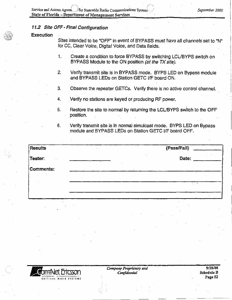
11.2 Site OFF - Final Configuration
Execution
Results
Tester: .
Comments:
Sites intended to be "OFP' in event of BYPASS must have all channefsset to "N" for ee, Clear Voice, Digital Voice, and Data fields.
1. Create a condition to force BYPASS by switching LCUBYPS switch on BYPASS Module to the ON position (at the TX site).
2. Verify transmit site is in BYPASS mode. BYPS LED on Bypass module and BYPASS LEOs on Station GETC JlF board ON.
3. Observe the repeater GETCs. Verify there is no active control channel.
4. Verify no stations are keyed or producing RF power.
5. Restore the site to normal by returning the LCUBYPS switch to the OFF position.
6. Venfy transmit site is in normal simulcast mode. BYPS LED on Bypass module and 8YPASS LEOs on Station GETC IfF board OFF..
(PassIFaU)
Date:
,
~ 1....+ Ertcsson J.JI.~_~ __ ._~." ____ " ___ " ... "_
Company Proprietary and Confuiential
9128/00 ScheduleR
Page 52 curlell lADIO STnEIIS
,

· .(\ Service and Access AgreeO for Statewide Radio Communications System. ,j State of Florida - Department of Management Services '
September 2000
11.3 Site ON - Final Configuration
Execution Sites intended to be "ON" and active in event of BYPASS must have channels intended to be active set to "Y" for ec, Clear Voice, Digital Voice, and Data fields, and inactive channels set to "N".
1. Create a condition to force BYPASS by switching LCUBYPS switch on BYPASS Module to the ON position (at the TXsite).
2. Verify transmit site is in BYPASS mode. BYPS LED on Bypass module and BYPASS LEDs on Station GETC IIF boards are ON. .
3. Observe the repeater GETCs. Verify there is an active control channel in the channel group allowed in the personality. (LED indicators L 1, L6 & L7 ON.) The remaining repeater GETCs should have L 1 and L7 ON.
4. Verify the station appearing as control channel is keyed, producing RF power and modulated with control channel data.
5. Verify a terminal radio set to the system programmed for the sitE? in BYPASS with the correct site 10 recognizes the site's control channel data.
6. Key the terminal radio on a group call.
7. Verify a working channel assignment is made within the channel group allowed in the personality.
8. Verify the call is heard on a second terminal radio set to. the active BYPASS system.
9. Restore the site to normal by returning the LCUBYPS switch to the OFF position.
10. Verify transmit site is in normal simulcast mode. BYPS LED on Bypass module and BYPASS LEOs on Station GETC IfF board OFF.
---... ',-rio Ertt:sson I!L~_~._ ........ _! ____ ._. __
CBlj:~&l IIDIQ 1.!Snl:
Company Proprietary and Confulentiai
9128/00 ScheduleB
Page 53
~----------~- ----~~ -------
'~ ' .. -
. I·. . .' \ ') ~-\. (
Serv:tce and Access A -_-,nt for StateWIde Radio CommurucatIODS Systek._ / State of Florida -Department of Management Services
Results
Tester:
Comments:
~ I~ Ertcsson "'~! .. ~-~--~.--.. -.:. .. -~---
CIITIt.ll. IADIO ITSTEIIIS
----------- ---_.---- ..... -'-- - - .- --.~-------... - ._.-.----- ----
Company Proprietary and Confidential
(Pass/Fail)
Date:
September 2000 . .
9128/00 ScheduieB
Page 54

l
Service and Access ~ ') for Statewide Radio Communications SysteC) State of Florida - Department of Management Sernces ..
September 2000 .
11.4 Control Point Trunking Reset Control .
Execution
A properly set up SimulQast BYPASS system will disable (hold in RESET) CPTCs aSsOCiated with active channels at a TX site operating in BYPASS. This keeps the remaining sites operating in Simulcast mode from being assigned to channels expected to be active at the site in BYPASS. Sites programmed to be OFF in BYPASS will not require any CPTCs to be held in RESET.
This test will verify that the Control Point CPTCs will be held in RESET corresponding to the active channels at a site as a result of the TX site being in BYPASS.
NOTE This procedure requires simultaneous activity at the Controi Point and Transmit Site.
1. Force a TX site that will become active into BYPASS by switchil}g LCUBYPASS switch on the BYPASS module to the ON position (at the TX site).
2. Verify TX site is in BYPASS mode. BYPS LED on Bypass module and BYPASS LEOs on Station GETC IIF boards are ON.
3. Observe the repeater GETCs. Verify there is an active control channel in the channel group allowed in the personality. (Station GETC L 1, L6 & L7 ON.) .
4. Verify the Control Point "E" leads have become "inactive" by observing that the BYPASS LED on the System Bypass board located at the rear of the Common Rack associated with the site in BYPASS is ON.
5. Verify the System Bypass board OVERRIDE LED is OFF for the site in BYPASS, and its RESET ACTIVE LED is ON.
6. Verify the CPTCs on the channels intended to be OFF are held in RESET. (All LEOs OFF.)
7. Observe the CSD site monitor screen for the simulcast system. Verify the channels intended to be OFF at the Control Point display GETC Poll Failure as a result of being held in RESET.
8. Restore the site to normal by returning the LCU8YPS switch to the OFF position (at the TX site). .
.~·I..-ri-Ertcs50n JJL~~~~~_ ....... _. __
Company Proprietary and ConfuJentiaJ
9/28/00 ScheduleB
Page 55 . CIITICAL RADIO STSTEIS
- -- ----- - --- ~- --~---
----~ ----- - --~~-~----.----.-----.-"---.-.-----.-.-.. --- --~----~ ~-- - --

. dA (\ S 'd D_." . . S if '\ Serv:tce an ccess Agr"-._,,ent for tateWl e ~o CommurucatlOns ys 1._../ September 2000 State of Florida - Department of Management Services
Results
Tester:
Comments:
9. Verify the TX site GETCs revert to normal Simulcast. CC has L 1, L2 and L7 ON; idle WCs have L 1 & L7 ON.
10.' Verify the Control Point uE" lead has returned to the "active" state by observing that the LED on the System Bypass board associated with the ' site in BYPASS is OFF.
11. Verify the System Bypass board OVERRIDE LED is OFF for the site in BYPASS, and its RESET ACTIVE LED is OFF.
12. Verify the CPTCs associated with the site in BYPASS are returned to normal (Not in RESET).
13. Verify CSD Call Monitor screen indicates GETC poll failures clear as a result of the CPTC RESET condition being cleared.
(PassIFail)
Date:
•
~ I~ Ertcsson "'''*?!~~-~-'-- ._-----
Company Proprietary and Confulential .'
9128100 ScheduleD
Page 56 CIITIC4l RigiD $-T$TEII;
- ------~--~--. ~---.. ---.-----~-----.--~-.- ... --.--.. ------".-.. ---~- ----~---------- --
----~----

Service and Access A~i for Statewide Radio Communications syster() . State of Florida - Depaii=tment of Management Services·-
September 2000
12~' PROVOBCE EDACS VOTER
Acceptance Test Procedure Version: Rev.B May 11998 Last Modification Date: .
12.1 Setup
This test will verify proper operation of the PROVOICE EDACSReceiver Voting System in the Analog and Digital modes, as well as the links between the Receiver sites and the Voting' equipment (Microwave/leased circuits & MUX).
These tests require two radios programmed with a clear voice talk group. The radio used for transmitting must be positioned to provide a full quieting (>12 dB SINAD) signal into all receiver sites under test. It may be necessary to use multiple transmitting radios at different locations to be able to r~ach all transmit and satellite receiver sites. For convenience .in testing, the Alignment radio in the Control Point Test Rack is suggested as the transmitting radio. A second radio is used for receiving, and needs to be in range of any transmit site. .
Set CSD channel assignments to rotate ascending.
~ I,,", Ertcsson IJL.~~ __ -_.~ __ ~._._. . .. _
Company Proprietary and Conjuiential
9128/00 ScheduleB
PageS7
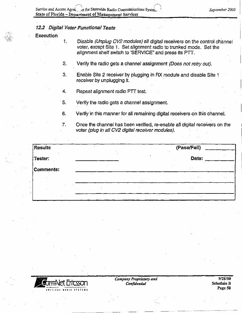
;
Service and Access AgrL)t for Statewide Radio CommUnications Syst[) State of Florida - Department of Mallllagement Services
September 2000
12.2 . Digitsl Voter Functionsl Tests
Execution
Results
Tester:
Comments:
i. Disable (Unplug CV2 modules) all digital receivers on the control channel voter, except Site 1. Set alignment radio to trunked mode. Set the alignment shelf switch to 'SERVICE" and press its PIT.
2. Verify the radio gets a channel assignment (Does not retry out).
3. Enable Site 2 receiver by plugging in AX module and disable Site 1 receiver by unplugging it.
4. Repeat alignment radio PTT test.
. 5. Veri·ty the radio gets a channel assignment.
6. Verify in this manner for all remaining digital receivers on this channel.
7. Once the channel has been verified, re-enable all digital receivers on the voter (plug in aI/ CV2 digital receiver modules).
(Pass/Fail)
Date:
~ 1.-.+ Ertcsson 1JL.~ __ ~ .. ,.t. .... _______ ..
Company Proprietary Ilnd Confidential
9128/00 ScheduleR
Page 58

( - r~
S . d· lc. S ·d· .. I) erVJce an Access Agreen.. ___ l J.or tateWI e RadIO Commumcations System> . . September 2000 State of florida - Departmellllt of Management Sernces
12.3 Analog Voter Functional Tests
Execution
Results
Tester:
Comments:
1 . Disable aI/ working channels at the CSD except the channel under test
2. Set the alignment radio to the trunked mode. Set the alignment shelf switch to "SERVICE" and press its PIT.
3. Verify the radio gets a channel assignment. ObselVe the working channel analog Yoter. All receive indicators should be iIIuminated·(Yellow), one selected indicator should be illuminated (Green).
4. Tum up the yolume control on the working channel analog voter. Speak into the alignment radio's microphone.
5. Verify audio is present at the voter speaker. Force select each analog voter receiver card one by one and verify audio is present at the speaker.
6. Monitor the call on another clear voice equipped terminal.
7. Verify originating terminal audio is heard.
8. Return all working channels to service upon completion of this test.
(PassIFaiJ)
Date:
~ '..-rio Em::sson IPA.~J'~~ ___ ... ____ _ Company PropnetaryQ,,,f
Confuientiai 9/28/00
ScheduleB Page 59 CIITiClL IUID ITST£H:
---------- --~--------------------

. \ ..... .
Service and Access AgreenCJfor Statewide Radio Communications systernC) State of Florida - Department of Management Services
September 2000
13. CENTRALIZED TELEPHONE !NTERCONNECT CALLS
Acceptance Test Procedure Version: Rev.B Jan 1 1998 Last Modification Date:
13.1 Radio Originated Interconnect Call.
Setup
Execution
This test requires a radio, one phone with known phone number, and CSD.
1. From radio, place a call to phone and observe that the call is assigned a channel on the CSD Cail Monitor screen. Ringing should occur at Phone.
2. Answer phone, and talk. Audio should be heard at radio. PTT radio and talk. Audio should be heard at phone.
3. Terminate the call from the radio and observe that call ends and channel is·released from Interconnect.
4. From radio, recall the prestored number to call phone, and PIT. Observe a channel is assigned for the call on the CSD Call Monitor screen. Ringing should be heard at phone.
5. Answ~r phone; audio should be heard at radio. PIT radio and talk. Audio should be heard at phone.
6. Select another site for radio and repeat the steps 1 thru 4. Monitor the second site at the CSD Call Monitor. .
7. Terminate the call from the radio.
8. Repeat the steps 1 thru 2 and continue the call until the channel times out. Verify.that the radio receives the dropout alert tone (only in analogue calls).
9. Repeat the previous steps for each channel configured for interconnect.
10. If applicable, repeat previous steps for digital voice .
~1~Ertcmn .. ~-.~ .. -.-. -_.!_---_._-Company Proprietary and
Confuiential 9/28/00
ScheduleB Page 60
-- --- -----~--~---.---.. ~--.. -----~---.-.-------

'd A () 'd ., (j Servlce an Access gI'eemc~. for StateWl e Radio Commumcatlons System '" State of Florida - Department of Management Services
Results
Tester:
Comments:
~ ''''''" Erit:sson IJIr.~E_·~ _~_ ... -- ... - .. _ Company Proprietary and
. Confidential
~~---------~ -~~ ----~--- - --"-~--.~--~-----~--'
(PassIFail)
Date:
September 2000
9128/00 ScheduleB
Page 61

Service and Access AgrLht for Statewide Radio Communications sysD State of Florida - Department of Management Services
September 2000
13.2 Telephone Originated Interconnect Call to Radio
Execution
Results
Tester:
Comments:
1. From the telephone, place an interconnect individual call to the radio according to the operator's manual. .
2. Verify ringing is heard at the telephone and the radio. While the radio is ringing, key the radio. Confirm that ringing is removed from the telephone and the radio. .
3. Verify that the call allows two way communication between the radio and the telephone.
4. Continue the ·call until the channel times out. Monitor the second at the CSD Call Monitor. Verify that the radio receives the dropout alert tone (only in analogue calls).
5. Select another site for the radio and repeat the steps 1 thru 3. Monitor the second site at the CSD Call Monitor.
6. Drop the call from the telephone and verify the radio has terminated the call.
7. Repeat the previous steps for each channel configured for interconnect.
8. If applicable, repeat previous steps for digital voice.
(Pas.S/Fail) ,
Date:
~ I~ EriLsson IJL,~~!.!~~_._ :. .._
Company Proprietary and Confidential
9128/00 ScheduleD
Page 62

, (~\ . n Service and Access Agreeml .. _l~r Statewide Radio Communications System \, / September 2000 State of Florida - Department of Management Semces
13.3 Telephone Originated Interconnect Call to Group
Execution
'Results
Tester:
Comments:
1. From the telephone, place an interconnect group call to the radio according to the operator's manual.
2. Verify ringing is heard at the telephone and the radio. While the radio is ringing, key the radio.
3. Confirm that ringing is removed from the telephone and the radio.
4. Verify that the call allows two way communication between the radio and . the telephone.
5. Continue the call until the channel times out
6. Verify that the radios receive the dropout alert tone (only in analogue calls).
7. Drop the call from the telephone and verify the radio has terminated the call.
8. Repeat the previous steps for each channel configured for interconnect.
9. If applicable, repeat previous steps for digital voice.
(Pass/Fail)
Date:
~ '''"' Ertcsson .. ~---~ .... -.. --~-.-----... - -
Company Proprietary Ilnd Confidential
9128/00 ScheduleD
Page 63 CRIOIeu alDID nUEIIS

" ~ .. -.. '
Service and Access A~lt for Statewide Radio Communications Syst~) State of Florida - Department of Management Services
September 2000
14. LOCAL DISPATCH FEATURE SET (C3 MAESTRO)
. Acceptance Test Procedure Version: Rev.C May 11998 Last Modification Date:
With the introduction of C3 Maestro for Windows NT,. multiple devices can be used for Dispatch Operations (Mouse, Touchscreen, Custom Keyboard, . Trackball). Consult the appropriate User Manual for specific instructiqns on how to use these various devices. This procedure is written to be as generic as . possible, but will assume a Mouse, Desktop MIC, Footswitch, 2 speakers and a Headset are installed when required.
These tests assume a valid UD/GID database with aliases defined for the test entities (test group structure as previous tests) has been setup, privileged and sent to Console under test, using the CEC/fMC manager. It also assumes 2 radios have been programmed with the above test entities.
14.1 Transmfftti~g With MIC Or Headset
Setup Unplug the headset
Choose a group to use as a test group
Program a radio with the test group.
Program a console module with the test group.
Review Console User Profile settings for Console under Test (Le. Audio . Indicators).
14. 1. 1 Group Call Execution
1. Press the iNSTANT TX function (for example right mouse button) on the module with the test group. Verify that a channel access tone is heard, the XMT indicator is displayed and that the cail is heard at the radio. Release the Instant TX key.
2. Press the SELECT button on the module with the test group. Verify that the SELECT indication for that module becomes highlighted.
S. Press the SELECT TX function. Verify that a channel access tone is heard, the XMT indicator is displayed and that the call is heard at the radio. Release the SELECT TX function.
Jk~t.!f~JfJPiS~J Company Proprietary and
Confulential 9128/00
Schedule B Page 64. CllTICAl RADIO nsrellS

,,-\ ./~
Service and Access AgrC __ .bt for Statewide Radio Communications sysU State of Florida - Department of MSlIlsgemen1t Services
September 2000
4. Press the PIT foot pedal. . Verify that a channel access tone is heard, the XMT indicator is displayed and that the caH is heard at the radio. Release the foot pedal.
5. Plug in the headset. Repeat the previous step.
14.1.2 Individual Call Execution
1. Program a module with the LID of the test radio. Select the console module with the test unit LID. Press the SELECT TX function. Verify that a channel access tone is heard, the XMT indicator is displayed and that the call, is heard at the radio. Release the SELECT TX function.
2. Plug in the headset.
3. Select the console module with the test LID. Press the SELECT TX function. Verify that a channel access tone is heard, the XMT indicator is displayed and that the call is heard at the radio.' Release the $ELECT TX function.
4. Unplug the headset.
14.1.3 Alert Tones . Execution
1. Press the SELECT button on the module with the test group. Verify that the SELECT indication for that module becomes highlighted.
2. ' Press and hold the foot pedal or 'Selected, Transmif key. The test radio will receive the call. While still transmitting, press one of the three alert tone keys (Alert, Pulse, Warble). Verify the alert tone is received by the radio and also heard on the console.
3. While not transmitting, press and hold one of the alert tone keys. Verify the console transmits on the selected group, the test radio 'receives 'the call, and the alert tone is heard by the radio and console. When the Alert tone key is released, verify the call drops.
Company Proprietary Ilnd Confuiential
CII!ItH llDID ST:IE~S
9/28/00 ScheduleR
Page 65
- ~-~--,---- ----~-------------.. ---.--------
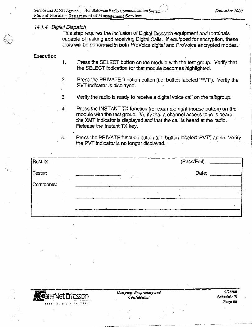
~\ . (~ Service and Access Agreeri.. jfor Statewide Radio Communications System' ,j September 2000 State of Florida - Department of Mallllagement Services
14.1.4 Digital Dispatch
Execution
Results
Tester:
Comments:
This step requires the inclusion of Digital Dispatch equipment and terminals capable of making and receiving Digital Calls. If equipped for encryption, these tests will be performed in both ProVoice digital and ProVoice encrypted modes.
1. Press the SELECT button on the module with the test group. Verify that the SELECT indication for that module becomes highlighted.
2. Press the PRIVATE function button (i.e. button labeled 'PVT'). Verify the PVT indicator is displayed.
3. Verify the radio is ready to receive a digital voice can on the talkgroup.
4; Press the INSTANT TX function (for example right mouse button) on the module with the test group. Verify that a channel access tone is heard, the XMT indicator is displayed and that the call is heard at the radio. Release the Instant TX key.
5. Press the PRIVATE function button (i.e. button labeled 'PVT') again. Verify the PVT indicator is no longer displayed.
(Pass/Fail)
Date:
~ '''"' Ertcsson ... GtJ~.!~ __ ~_ .... ___ .. _ Company Proprietary and
Confidential 9128/00
ScheduleD Page 66 ClInCH RADIO STnEJI~
- -- -~ -~- - ---~---------- ---~-----~ -- ~ --'~-

/) .. r' Service and Access AgreeJ .. __ " for Statewide Radio Communications System(_) State of Florida - Department of Management Services
September 2000
f,
14.2 Receiving Calls
Setup Unplug the headset.
Set and send 'Display ID for Alias' on the IMC Manager- Configurs Console User Profile for the Console' under test.
Program the test group into a module.
Set a radio to the test group.
14.2. 1. Group Call Execution
1. Unselect the console module with the test group. Key the radio and verify that the call is heard at the Unselect speaker and that the calling radio LID and the Call Indicator are displayed.
2. Select the console module with the test group. Key the radio. Verify that the call is heard at the select speaker and that the calling radio LID and the Call indicator are displayed.
3. Plug in the headset.
4. Select the console module with·the test.group. Key the radio. Verify that the call is heard in the headset and that calling radio LID and the Call Indicator are displayed.
5. Unplug the headset.
6. Key the radio. Verify that the module call light is on, the; call is heard at the Select speaker and the calling radio LID is displayed.
14.2.2 Individual Call Execution
1. Program a module with the LID· of the test radio~
4. Select the console module with the test unit LID. Call the console from the radio . (lCALL with Console UD). Verify that the call is heard at the select speaker and that the calling radio LID and the Call Indicator are displayed.
3. Plug in the headset.
4. Select the console module with the test LID. Call the console from the radio. Verify that the call is heard in the headset.
~ '''"'.Ertcsson "~It1~~ ... __ ~ _____ _ Company Proprietary and
Confuiential 9128/00
ScheduleD Page 67 ~ a I T I ~ 4 l I A a I 0 $ T ;. r E U ;

- (~I S -d - - S ("\ SeIVlce and Access Agreemerk J tateWl e Radio Commurucatlons ystem \ j) September 2000 State of Florida - Department of Management Services
5. Unplug the headset.
14.2.8 Call History Setup
Execution
This tests compares programmed module call activity to the history scroll lists. Utility page, dispatch menu will be selected. Select either the "Select History" or "Unselect History".
1. Press the 'Scroll Up' and 'Scroll Down' buttons to scroll through the Unselect call history list. Compare these calls with known activity.
2. Press the 'Scroll Up' and 'Scroll Down' buttons to scroll through the selected call history list. Compare these caBs with known activity.
3. Press the 'Esc' button to exit the history scroll mode.
4. To monitor call history on a single group use the 'module historY-button (oothe 'module modify' menu. Use the 'scroll up' and 'scroll down' buttons to scroll· through the calls for the picked module. Compare these calls with known activity.
14.2.4 Digital Dispatch
Execution
This step requires the inclusion of Digital Dispatch equipment and terminals capable of making and receiving Digital Calls. Console operation with respect to following the state of the last call received can be changed by the Console User profile at the IMC Manager. .
1. Press the SELECT button on the module with the test group. Verify that the SELECT indication for that module becomes highlighted.
2. Press the PRIVATE function button (Le. button labeled 'PYT). Verify the PVT indicator is displayed.
3. Key the radio. Verify that the call is heard at the select speaker. Verify that the call is heard at the select speaker and that the calling radio LID and the Call Indicator are displayed.
~ I,,"" Ertcsson ,..~~~.~ .....
· Company Proprietary and Confidential
9/28/00 Schedule B
Page 68 C I ( TIC ~ l Ie' DID $ Y S I EllS

! ~ :
S4226313
I ,
PARKjNG
P1~I~iNG TAX GIJE1SJ ROOM VS ·~·~·'"'·'''9394
:Cf2? ' DouII LETR,EE'!
GRAND KEY RESOR1T ,-- ~\V'n ---I'
R.oom Arr-iv~J Da!~ I lJep:ll111re Date , I Adu([/Child i Room Rltte i
! RAre PLAN, LVO HH# 878570887 OlAMON!:) AI.;OL #224225176$ CAR: i '
I
DHSCRrp'I'ION
, ~ BAI.ANCE: " •
:-.- ,~
yp
, .. ' , ,~ ..... ',', .'.' ~"., ~. :~).':!:,,',,!,:' '. :;. .' j:, -:~ \~ . ~.
:. ", ',':(' .:... .. \
"
! $10.00 $0.75
r $12'1,00 (~131.75) •
$0.00
'.' Dnuo LIiTR.lJ 11' UIII, U'.lI"-,,.rh'(I ... ,,::~ .. u ..... '1) ...... , J.~""Na
""''''.;r.II-

Service and Access Ai/;nent for Statewide Radio Communications sr) State of Florida - Department of Management Services ...
Results
Tester:
Comments:
~ f,-,+ Ertcsson .. ~~_. __ ._.~. ___ ~._.. •• _e' ._ ••• _ .... __
Cll~!C.L RADIO Sl~I[II$
COmpany Proprietary and Conjuientiai
(Pass/Fail)
Date:
September 200(
9128/00 ScheduleB
Page 69 / .

Service and Access Agreemen~/') S~tewide Radio Communications System C) State of Florida - Departmiielllt of Management Services
September 2000
14.3 Emergency Call
Setup
Execution
Results
Tester:
Comments:
This test requires a test radio capable of generating and clearing an emergency (Le. Supervisor Radio).
1. UNSELECT the test group. Using the test radio, declare an emergency on the test group .
. 2. Verify the module turns red, the 'EMER' flag is briefly displayed in the module, the LID/Name of the test radio is displayed, the emergency message is displayed in the message window, and the emergency alert tone is heard on the console.
3. Pick the module with the emergency and depress 'Alarm Resef. Verify the alert tone is silenced on the console, but the emergency is still displayed:
4. Select and transmit on the group with the emergency~ Verify the test radio receives the call, and is still in emergency mode.
5. Clear the emergency using the 'EMER CLR' key. Verify the module no longer indicates an emergen9Y.
6. Transmit on the test radio and verify the emergency is cleared and normal group calls have resumed.
7. With the. test group selected on the console, declare an emergency on the test group. Verify the console and radio have the same indications as steps 2to 4.
8. Clear the emergency with the console.
Company Proprietary and Confidential
. (Pass/Fail)
Date:
C R I : i C 11. R' D I 0 : 1 IrE II $
9128/00 ScheduleB
Page 70
!

Service and Access Agreen/-\for Statewide Radio Communications System n " /,-State of Florida - Department of Management Services '
September 2000
14.4 Agency Broadcast
Setup
Execution
Results
Tester:
Comments:
Unplug the headset
Choose an agency to use as a test group
Program at least two radios with different subfleets but in the same test agency.
, Program a console module with the test agency.
Review Console User Profile settings for Console under Test (Le. Audio Indicators). '
, 1. Press iNSTANT TX on the module with the test agency. Verify that a channel access tone is heard, the XMT indicator is displayed and that the call is heard at the radios. Release the Instant TX key.
2.' Press the SELECT button on the module with the test group.' Verify that the SELECT indication for that module becomes highlighted ..
3. Press the SELECT TX function. Verify that a channel access tone is heard, the XMT indicator is displayed and that the call is heard at the radios. Release the SELECT TX function.
4. Press the PTTfoot pedal. Verify that a channel access tone is heard, the XMT indicator is displayed and that the call is heard at the radios. Release the foot pedal. '
5. Plug in the headset. Repeat .the previous step.
(Pass/Fail)
Date:
.~ 1....+ Ertcsson "~~.!~!!~~~--.--~.--
Company Proprietary and Confidential
9/28/00 Schedule B . Page,7! Cllf:CU I&DIO nSfEIU

/~ .r Service and Access Agreem6 Dr Statewide Radio Communications System '\, ) State of Florida - Department of Mallllagement Services ..
September 2000
14.5 Patch
Setup
Execution
Do not include entities with privileges on Failsoft sites in thi~ test.
Program four test groups. The groups must not be fleets or agencies. The groups shall be selected in such a manner so as to test patch operation at the Tier 3 (inter IMC) level. In other words, the patch must be active across multiple IMCs;
Have on hand, 2 radios programmed with 2 of the test groups and logged on to sites.
1. Create a 4 group patch on PATCH 1.· Verify that the ACTIVE indicator for P~TCH 1 (Le. P1 indicator in each module) comes ON and the four modules are included in the patch.
2. De-activate PATCH 1 and verify that the ACTIVE indicator goes OFF.
3. He-activate PATCH 1. Verify that the ACTIVE indicator comes back ON.
4. Modify PATCH 1 by removing two of the groups in the patch. Verify this results in a two group patch. Verify t.hat the patch indicators of the two remaining groups are ON and the patch indicators of the two deleted groups are OFF.
5. Set each radio to a different test group in the patch and tum scan off.
6. Activate and Select PATCH 1.
7. Key one of the radios on its test group. Verify that the call is heard at the other radio and at the select speaker.
8. Repeat the previous step, except key the other radio . .. ~'. . .
9. Key the console by pressing the transmit bar. Verify that audio is heard at both radios.
Company Proprietary and Confidential
CRITICAL IAGIO SlS1tlS
9128/00 ScheduleB
Page 72

Service and Access Agreem{ -)r Statewide Radio Comm~cations System n State of Florida - DepartJiDent of Management Services ---
Results
Tester:
Comments:
C111!tAt RADIO STS1EKS
Company Proprietary and ConjuJential
(Pass/Fail) .
Date:
September 2000
9J28/00 Sclb.edule JB
Page 73

\ (~\ Service and Access Agre()t for Statewide Radio COmD1UIlIcatiOns SysteJ.... / State of Florida - Department of M::,;,:a.:::na:tg~em=elIll::.::t;.;S;.;ervJl;;.;.;.;·c;.;es;....., ___ -___ ~ ________ _
September 2000
14.6 Simulselect
Setup
Execution
Results
Tester:
Comments:
This test applies to Level 1 (Single Site, Simulcast, and Voted) sites only. Program four test-groups. The groups must not be fleets or agencies. Have on hand 2 radios programmed to 2 of the test groups and logged on to site.
1. Create a 4 group Simulselect on the 4 test group modules. Verify that the ACTIVE indicator (Le. 81 displayed in each module) for SIMUL8ELECT t comes ON and the SELECT indicators of the 4 group modules are ON and highlighted, respectively.
2. Un-select 81MULSELECT 1 and verify that the active indicator goes OFF.
3. Re-activate SIMULSELECT 1. Verify that the ,ACTIVE indicator comes ON.
4. ' Modify SIMULSELECT 1 by removing two of the groups in the-Simuiseiect. This results in a two group Simulselect. Verify that the . ACTIVE and SELECT indicators of the two'remaining groups ?re ON and highlighted, respectively and the ACTIVE and SELECT indicators of the two deleted groups are OFF.
5. Set one radio on each of the test groups in the Simulselect and turn scan off. Activate and select SIMULSELECT 1. Key one of the radios on its test group. Verify that the, call is heard at the select speaker and not at the other radio.
6. Repeat the previous, step, except key the other radio.
7. Transmit from the console on SIMULSELECT 1. Verify that audio is heard at both radios.
(Pass/Fail)
Date: ____ _
~9iC~!) Company Proprietary and
Confuien'tial 9128/00
ScheduleR Page 74 CIITIeAl RiOlO S.TSTE~$

Service and Access Agre/~--'\t for Statewide Radio Communications Systt~.) \ / ~
September 2000 State of FBoridla - Depalftmelllt of Managemelllt Services 0
14.7 Console Pre-Empt
Setup Choose a group to use as a test group
Program two radios with the test group.
Program a console module with the test group.
14.7. 1 Clear Voice Dispatch Execution
1. Key the first radio on the test group and hold the call up. Verify that audio is heard at the second radio and the console.
2.' Key the console on the test group and hold the second, pre-empting call up~ Verify that the XMT indicator is displayed along with the pre-empted caller LID and CALL indicator. Verify that the second radio begins to hear the console audio and not the first radio call. Verify that the pre-empted radio audio is still heard on the pre-empting console.
3. Unkey the first radio. Verify that the pre-empted caller UD and CALL indicators are removed and the pre-empted radio audio is no longer heard on the pre-empting console.
4. Unkey the console. Verify that the call drops.
14.7.2 Digital Dispatch
Execution
This step requires the inclusion of Digital Dispatch equipment and terminals capable of making and receiving Digital Calls. Digital Pre-empt must be configured at the Trunked System before this test can be performed.
1. Press the SELECT button on the module with the test group. Verify that the SELECT indication for that module becomes highlighted.
2. Press the. PRIVATE function button (i.e. button labeled 'PVT'). Verify the PVT indicator is displayed.
3. Verify the radios are ready to transmit! receive digital voice calls on the talkgroup.
4. Key the first radio on the test group and hold the call up. Verify that audio is-heard at the second radio and the console.
5. Key the console on the test group and hold the second, pre-empting call up. Verify that the XMT indicator is displayed along with the pre-empted

Service and Access Agreem(~or Statewide Radio Communications System ~) September 2000 State of Florida - DepartInel!lt of Management Services '
6.
7.
Results
Tester:
Comments:
caller LID and CALL indicator. Verify that the second radio begins to hear the console audio and not the first radio call. Verify that'the pre-empted radio audio is still heard on the pre-empting console.
Unkey the first radio. Verify that the pre-empted caUer LID and CALL indicators are removed and the pre-empted radio audio is no longer heard on the pre-empting console.
Unkey the console. ,Verify that the call drops.
,-
CDmpany Proprietary and Confidential
(Pass/Fail)
Date:
CIiTICAl U:DID snTEI:
9/28/00 ScheduleR
Page 76

Service and Access Agre()1t for Statewide Radio Communications syslj September iooo State of Florida - Department of Management Services ..
14.8 Console to Console Interaction
14.8.1 Console Intercom Setup
Execution
This test requires two consoles located on the same IMC. The console under test will be referred to as console A and the other console will be B.
1. On Console A, program a module with the console ID of console B. Select this module and transmit.
2. Verify on console A that 'RING' is displayed in the module. Verify that on console B, a blank module has been automatically programmed with the console ID of console A, 'CALL' is displayed in the module, the intercom call message is displayed in the message panel, and the intercom alert tone is heard. .
3. Answer the call at console 8 by picking the console A module and pressing 'Call Answer. Verify the intercom alert tone silences at console B and the display in the module on both consoles changes to 'ACTV'. .
4. At console A, press the 'ICOM TX' button and talk. The audio should be heard on console B. At console 8, press the "COM TX' button and talk. The audio should·be heard on console-A.
,
5. At either console, press the 'ICOM Call Hold' button. Verify the module indicator changes to 'HOLD'. Press 'ICOM Call Hold' again and verify the display changes back to 'ACTV' and the intercom can be used again.
6. At either console, press the 'Call Release' button. Verify the module . blanks on console B and the display on console A no longer shows 'ACTV'
14.8.2 Console Crossmute Setup
Execution
Establish two consoles (A and 8) to test the Crossmute function. The Consoles must be on the same CEC/ IMC. Program and select a test group on both consoles.
1. Place a call on console A on the test group.
2. Verify that console B can hear console A in the select speaker.
3. At console S, mute console A.
Company Proprietary and Confuiential
CRITiCAl IADID SYSTEIIS
9128/00 ScbeduJeB
Page 77

S · d . rf\s·· .. (\ ervtce an Access Agreeml~~.br tateWlde Radio Conunurucations System ~j September 2000
State of Florida - Department of Management Services
4. Place a call on console A on the test group and verify that it cannot be heard at console 8.
5. Restore the desired cross mute setup.
Results
Tester:
Comments:
~ 1,..+ Em:sson JJJA.~'!!!_~_~ ___ .. _ .. ____ _
CRITICAL ROIO STHt.~
Company Proprietary and Confuiential
(Pass/Fail)
Date:
9128/00 ScheduleB
Page7S

Service and Access Agreem(br Statewide Radio Communications System (') . State of Florida - Department of Management Services '-j
September 2000
14.9 Supervisor Console
14.9. 1 Priority Override (Pre-empt) Setup -
Execution
This test only applies to consoles that have been programmed as Supervisors. This test also requires the use of a console that is not programmed as a . supervisor, and a test radio.
1. Place (and hold) a call at the non-supervisor console on the test group~ Verify this call is received by the-test radio.
2. At the supervisor console, transmit on the same test group.
3. Verify that the audio heard on the radio is the audio from the supervisor's console and not the audio from the non-supervisors console.
4. Unkey both consoles.
14.9.2 Console Enable/Disable Setup
Execution
This test only applies to consoles that have be~n programmed as Supervisors. This test also requires the use of a console that is not programmed as a supervisor, and a test radio.
1. From the supervisor console periorm a console disable function on the non-supervisor console.
2. Verify that the non-supervisor console indicates disabled. Attempt to transmit, and verify the console is unable to transmit to the test radio~
3. Re-enable the non-supervisor console from the supervisor console.
4. Verify that the non-supervisor console becomes functional again by transmitting to the test radio.
a~_~ __ gLCS~_~ Company Proprietary Ilnd Confuiential
9128/00 ScheduleS
Page 79 ell:! c ~ L Il.D lOS T S r £ M·S
---------"-----------------.----.------~---~--- - ~- ------~- --- ------- ----------- ---~

Service and Access Agret()t for Statewide Radio Communications SY:;te(-") State of Florida - Department of Management Services . ~
September 2000
14.9..3 Unprogrammed Emergency Setup
Execution
Results
Tester:
Comments:
This test only applies to consoles that have been programmed as Supervisors. It requires a test radio capable of generating an emergency. The console should not be programmed with the radio's test group. The group must be in the console's privilege list unless the console is also programmed to route an unprivileged emergency.
1. Using the test radio, declare an emergency on a group not programmed in the console. Verify the console automatically programs an unused module with the group the emergency was declared on.
2. Verify the module un-programs from the console when the emergency is cleared.
Company Proprietary Ilnd Confuiential
(PaSS/Fail)
Date:
C t f Tie 1 L. a A DID S T S r E .. :
91lS/00 Schedule B
Page 80

Service and Access AgreQ£r~)'or Statewide Radio Communications System(") \ ' -~ ---
Seplember 2000 State of Florida - Department of Management Sernces -
14.10 Conventional interlace (el)
Setup
Execution
Results
Tester:
Comments:
This procedure is repeated for each channel in the CI, interface. Some of the functions tested may not be present for the channel under test.
Program the channsl under test at a console. Obtain a conventional radio with the capability to operate on the channels under test.
1. Transmit on the radio and verify that the call is heard at the console. For multiple, frequency stations, repeat the test for each Rx, frequency.
2. Transmit from the console and verify that audio is heard at the radio. For multiple frequency stations, repeat the test for each Tx frequency selected on the console.
(Pass/Fail)
Date:
AANet Ericmn = ----- ----- ,Company Proprietary and ' ConjidentUzl
9128/00 ScheduleS
PageSl _ Clli!CAL UDID ;THEil:

. Service and Access A~}t for Statewide Radio Communications syst~) State of Florida - Department of Management Services . -
September 2000
14.11 .Telco Interconnect (Call Director)
Setup The CSD must have an assigned call director LID for the cOQso'e .
. The IMC Manager (MOM) must have the call director and the matching call director LID from the CSD. This data must be sent to the console from the IMC Manager (MOM).
Call Director must be enabled on the console.
The telephone number for the Call Director Interface to the PBX or PSTN must be connected and working.
14. 11 .. 1 Answering a Call Execution
1. Establish a call by dialing the Call Director telephone number and then answering the call at the Console.
2. Verify the phone audio is heard in the select speaker along with select audio.
3. Transmit on the CD TX. Verify the Dispatcher audio is heard on the phone audio and the phone audio is not heard on the select speaker.
4. Release the CD TX. Verify the Dispatcher audio is not heard on the phone audio and the phone audio is heard on the select speaker along with select audio. .
5. Select and TX on the module. Verify the Dispatcher audio is heard on the radio, but not on the phone audio.
6. Release the phone line from Call Director equipment. Verify the Console has -hung-up· the phone. No CD audio should be heard in the select speaker, and the COOH status is not displayed on the status pan~1.
7. Key a radio on the selected module; Verify the audio is heard in the select speaker.
Company Proprietary and Confuiential
tRIT!tAL UBIB snTEII:
9128/00 ScheduleB
Page 82

Service and Access Agree(;; for Statewide Radio Communications syst~) State of Florida - Depsiimel!D.t of Management Services " . /
September iooo
14.11.2 Patching a Call
Execution
A call director patch is activated by pressing <AL T>+<MODULE SELECT> from the keyboard or by the Call Dir. Patch button using the mouse/touch screen, when a module is picked.
1. Establish a call by dialing the Call Director telephone number and then answering the call at the Console.
2. Verify the phone audio is heard in the select speaker along with select audio.
3. Transmit on the CD TX. Verify the Dispatcher audio is heard on the' phone audio and the phone audio is not heard on the select speaker.
4. Release the CD TX. Verify the Dispatcher audio is not heard on the phone audio and the phone audio is heard on the select speaker along with select audio. Unselect the module.
5. Pick the module and activate the call director patch. Verify the XMT indication is displayed and the alias background is tan, telephone audio is heard on the Unselect speaker and the radio shows Trunked call.
6. Key the radio. Verify the radio is heard on the telephone and in the Unselect speaker.
7. Unkey the radio. Verify the phone audio is heard on the Unselect speaker and on the radio.
8. Select the module. Verify phone audio is heard on the select speaker and on the radio and the alias background is green.
9. Key the radio. Verify the radio is heard on the telephone and in the select speaker, phone audio is heard on the select speaker even if the radio is transmitting.
10. Unkey the radio.
11. Deactivate the call director patch. Verify the XMT indication in the module is erased and the alias background is,normal.
, ,
~ I,","" Ertcsson ~~!!!l~~~_. __ .. _~ .. __
Company Proprietary and Confuiential
9128/00 Schedule B
Page 83 CRI7iCll a!DID STSlEUS

S~ce and Access Agre0nt for Statewide Radio Co~unications SystC; State af FHarida - Department of Management, Sernces . /
Results
Tester:
Comments: , ,
CllilCH RADIO STlTE!1:
Company Proprietary and . Confulential
(Pass/Fail)
Date:
September 2000
9/28/00 Schedule' B
Page 84
----_.--_.----- .. _-------._.----- ------------ --- - - ---------------------- -- ------- -----------------~.~-
-------.----.-.. ~---

Service and Access Agree() for Statewide Radio Communications Syst~) State of Florida - Department of Management Services
September 2000
14.12 Logging Recorder
Setup
Execution
Results
Tester:
Comments:
Obtain the recorder channel list showing the recorded groups and individuals. If the recorder channel mapping has not been done or needs revision, complete this at the IMC/CEe Manager prior to running this test.
1. Place the recorder in a "monitor modeu allowing listening to the selected track.
2. Place calls to each of the group IDs and individual IDs that are on the list to be recorded.
3. By listening to the recorder in monitor mode, verify that the GID / UD to track correlation is correct and that audio is heard.
4. If applicable, repeat for digital dispatch.
Company Proprietary and Confidential
(Pass/Fail)
Date:
CRITiCAL UCID :TSTEUS
9/28/00 ScheduIeB
Page 85

Service and Access Agre;e( 1 for Statewide Radio Communications systeti:l State of FHorida - Department of Management Services --
September 2000
15. PROSOUND ROAMING
Acceptance Test Procedure Version: Rev. A Jan 1 1998 Last Modification Date:
Setup The two radios used for this test must be capable (feature encrypted) and programmed for ProSound. The radios rhust be valid on the systems being used to conduct the tests. The priority scan feature should be disabled. In addition verify that the Tone Suppress Option is not selected in the personality so that an audible tone can be heard once the radio ProSound switches to the new system.
Program Radio 1 for Dynamic Scan mode and remove all systems from the System Scan List in the personality file .
. Radio 2 can be programmed in either Fixed or Dynamic mode, as long as the adjacent system scan list is correct and available for use by the test radio. (For FIXed ProSound the adjacent system scan list must be programmed into the radio through the personality file. For Dynamic ProSound the adjacent system scan list must be programmed into the IMC, through the IMC Manager, in order for the adjacent system information to be broadcast out over-the-air). In either mode the tester must verify that the IMC and the systems under test are properly configured to broadcast the adjacency information used to locate the adjacent systems and control channel number of each.
{In summary: Fixed ProSound uses the adjacent system information provided over-the-air for the location of the control channel only, while Dynamic ProSound uses the adjacent system information for both the location of the control channel and the adjacent systems fist}.
Note that the display and indications of each model of radio differ. This test describes the general procedure for ProSound Roaming. Refer to the specific radio operators manual or the ProSound Release Notes for details ..
~ ~f"t'"A"W"iI - '- U I\.»JI A _.. -.. ~-.. -.--- .----. ----
Company Proprietary and Confuiential
9128/00 ScheduleD
Page 86 CIIT/eil UDIO lonu:
--------.--~.

Service and Access Ag:{=:Jent for Statewide Radio Communications syi:=J State of Florida - Department of Management Services
september 2001
·15.1· Adjacency Broadcast
Execution
Results
Tester:
Comments:
. This test verifies that adjacency information ;s being sent out over-the-air and received by the terminals. This test provides confidence that the PROVOICE EDACSsystem is echoing the "Adjacency Information" and that the terminals are properly receiving the messages. However the user must still verify that the correct information is programmed into the IMC Manager.
1.
2.
3.
4.
Turn Radio 1 on, and select a system that can been seen by the radio.
Wait 2 minutes, to allow the terminal to receive the "Adjacency Information" over-the-air.
Remove the terminal's antenna, causing it to lose the control channel signaling.
If the terminal enters the Wide Area System Scan Mode, then it is receiving the adjacency information and has .built its adjacent system list from the information provided. (If the terminal remains in Control Channel (CC) Scan and does not enter the Wide Area System Scan Mode, then it is NOT receiving the adjacency information.)
(Pass/Fail)
Date: _____ : i
~!,..n. Ertt:sson IJL~!!~_~ .. _. ____ ~_._ .... ____ _
Company Proprietary and Confidential
9/28/00 ScheduleB
Page 87 CIlTiOl RJDID ST$TEII:
-----------------

Service and Access AgC)~nt for Statewide Radio Communications syi.~ State of Florida - Department of Management Services
September 2000
1'5.2 Roaming
Execution 1.
2.
3.
4.
5.
Results
Tester:
Comments:
Log Radio 2 onto the weaker of the two systems to be used for this test. Ensure the radio is communicating on this system. (If the radio is unable to maintain communications with this system, the tester may need to move closer to the system) ..
Verify the name or indication of this system.
Begin traveling toward an area where the coverage from the second system is stronger than the coverage from the present system that the radio is logged onto.
As you travel away from the present system, towards the second system, the signal quality of the first system will deteriorate. Once the signal Jevel of the second (now stronger) system exceeds the programmed ProSound parameters in the personality, the radio will switch to the second system. The radio will generate an audible tone and will visually indicate that is has switched to the second system.
After the radio has switched to the second system, verify communications continue.
Company Proprietary and Confuiential
(Pass/Fail)
Date: ____ _
CRI!ICAL IADIO ST~rE.S·
9128/00 Schedule B
Page 88

Service and Access A~Jnt for Statewide Radio Communicatio~ Syst6J , State of Florida - Department of Management Services
September 2000
16~ COMMUNICATIONS SYSTEMS DIRECTOR (CSO) FEATURE 'SET
Acceptance Test Procedure Version: Rev. A Last Modification Date: Aug 12 1999
16.1 Setup
Database Prqgramming
If not already created, create the toll owing test groups (use customer or generic test structure):
(Group A) - Agency 1, Fleet 1, Subtleet 1 (Group 8) - Agency 1, Fleet 1, Subtleet 2 (Group C) - Agency 1, Fleet 2, Subfleet 1 (Group D) - Agency 2, Fleet 1-, Subfleet1 (Additional test groups may be useful.)
, How to Greate Groups
Select CSD Group Management Icon on desktop. Enable Write Mode ("Lock- Icon on toolbar). Select Groups. Select ALL folder. Select EDIT on pull-down menu. Select NEW. Create a t~st group at this time. Select OK. Right-click on group created. Select PROPERTIES. ' Modify the parameters:
Enable the groups on all sites and for Wide Area, interconnect, and special call, if applicable.
Select OK. Select FILE on pull-down menu. Select UPLOAD. Wait for the upload process to complete. Close out screen.
If not already created, create 4 LIDs with the test structure given above.
~ '''''"" Ericsson .. ~~_._.~ _ .... ___ 0,_-
Company Proprietary and Confidential
---~-----" ~-----~-------~-
9128/00 ScheduleB
, Page89
---~ ---- ~-------

\,
Service and Access Agre{)t for Statewide Radio Communications systlr-~ State of Florida - DepUtment of Management Sernces·
j
Creating LIDs
Select CSO Unit Management Icon on Desktop. Click on -Lockll Icon on toolbar to enable 'Write Mode. Select ALL UNITS folder. Select EDIT on pull-down menu and s~lect NEW. Create unites). Select OK. Highlight created unit and right-click. Select properties and modify unit. . Click OK and repeat for multiple units. Select FILE on pull-down menu and select UPLOAD. Close out screen after upload is completed.
For conventional channels, insure the validity of the database entries.
September 2000
Go· to CSD System and Device Management and locate the conventional site. Double click qn the site and review the parameters.
Modify the parameters if applicable and upload the information ..
Upload the appropriate databases to the sites and CEC/IMC.
Synchronize the Communications Systems Director clock with CEC/IMC Manager.
To upload time, select eSD System and Device Management Icon on desktop. . Select OPERATIONS on pull-down menu. Select UPLOAD and CURRENT TIME. Close out window when upload is finished.
tll!lC~L.I'DID tTSrEMS
Company Proprietary and Confuiential .
9128/00 Schedule B
Page 90
---------~---.---.----- .... _------_ .. _'

Service and Access Agr~ent for Statewide Radio Communications Systn State of Florida - Depirtment of Management SerVices . "-./
September 2000
16.2 Site Reconfigursfion
Setup
E:xecution
Results
Tester:
Comments:
One radio is required. Enter the System and Device Management and select one of the sites.
1. Change the settings to disable the highest used channel (channelS in a 5-channel system).
Site 'Reconfiguration
Select the System and Device Management Icon on the Desktop. Enable Write Mode by selecting the alack- Icon on the toolbar. Select the corresponding IMC, System, and Site. Double click on the site and select CHANNEL SUMMARY. Modify parameters. Select FilE then SAVE under the pull-down menu. . Click the ·Upu arrow (Upload) on the toolbar to upload parameters.
2. Verify that a display on the screen appears indicating thatthe upload was successful.
3. log a radio into'the system.
4. Verify that the highest used channel is disabled by placing multiple calls on the site under test and verifying that the site does not assign the disabled channel to a call. .
To monitor the site, select the CSD Call Activity Monitor Icon on the Desktop. Select corresponding site and click OK.
5. Return the database to its original configuration.
( Pass/Fail) ..
Date:
· Company Proprietary and ConfuJential .
cal!le&! R&OIO fYUIIIS
9128/00 ScheduleB
Page 91

Service and Access Agree(\t for Statewide Radio Communications Systenf) State of Florida - Dep~rtIDent of Management Services . '~'.
September 2000
16.3 Communications Systems Director Communication
Setup
Execution
Results
Tester:
Comments:
Two radios with a talk group are required.
1. Invalidate the talk group in'the GID definition database.
Select the CSD Group Management Icon on the Desktop. . Enable Write Mode. Select " ALL".
, Select applicable group. Right-click on group and select Network Operations. Modify Valid Sites and click OK. Select FILE and UPLOAD on the pun-down menu and click OK. Onc~ upload process is complete, close screen.
2. Verify that communication on the test talk group is not possible on the system by attempting to' key up radio 1. A grant tone should not be heard at radio 1 nor should audio be heard on radio 2. .
3. Revalidate the test talk group in the GID·definition database and upload the change.
4. Verity that communication on the test talk group is now possible.
5. Select the site to be monitored at qSD Call Activity Monitor.
6., Verify that site activity is being monitored.
,
Company Proprietary and Confidential
(Pass/Fail)
Date:
CllllCH RADIO STnEIiS
9/28/00 Schedule B
Page 92
- .. -.. ----.------~-----.----.----~~~-. . -.- --~--.----.. -~--,--~.-------.-----.-----------.--

.'
Service and Access Agre{)t for Statewide Radio Communications Systen.(j State of Florida - Department of Management Services
September 2000
16.4 Communications Systems Director Reports
Setup
Execution
Results
Tester:
Comments:
Identify a site/device, a radio and a group for which reports are to be generated.
1. Select CSD Reports on the Desktop and follow the menu to generate a site/device report for the desired site/device.
Select CSD Reports Icon on the Desktop. Select FILE under the pull-down menu or the "Wandfl
, RUN WIZARD Icon on the toolbar. ' Select DEVICES and cliCk next. Select the parameters needed in the next few screens. Click·FINISH and the report will be generated.
2. Select the Units folder and select desired report. Follow the menu to generate a Logical report for the desired LID. .
3. Select the Groups folder and select desir~d report. Follow the menu to generate a Group report for the desired GID.
4. Verify that the content of each report reflects the information in the databases. Delete each report whe~ finished.
Company Proprietary and Confidential
(Pass/Fail)
Date:
ell : 1 C 'l l.l 0 I. 0 ~ T t T filS .
9128/00 ScheduleB
Page 93

Service and Access Agre(--)t for Statewide Radio Communications SysteC) State of Florida - Department of Management Services .
September 2000
16.5 System Maintenance
Setup
Execution
Results
Tester:
Comments:
;
Identify user accounts for other users who will require access to the Communications Systems Director. Obtain spare tapes for archive.
Note that the Communications Systems Director will be unavailable for use for . extended periods during archive, retrieval, and backup tests.
1. Select CSD Group Management Icon on Desktop and ensure that the AFS structure is as required.
Double click the USERS folder and select user to be modified. Right-click on the user and modify parameters.
2. For System Backup, refer to Com-Net Ericsson manual AElLZT 123 3434/1 ~ Section 9.1 Backup and Restoration Using Seagate Backup Exec.
(Pass/Fail)
Date:
~1~Em:sson .. ~~~~ _ ... '
Company Proprietary and· Confuiential .
9128100 ScheduleB
Page 94

Service and Access Agrj~)t for Statewide Radio Communications Systei") State of Florida - Department of Management Services
16.6 Activity Download
Setup
September 2000
This test will perform a download only. The activity will be inspected later in . these tests.
Execution 1 . Select the CSD Reports screen and follow the directions on the screen.
Select the site number of the site to which the download request is to be sent. Execute the download request.
2. Verify the Report was generated.
Results
Tester:
Comments:
~ l..w Ertcsson IILGtJf·~~~ _____ .... _
CIl!lell RUID onEIiS
---- ._--------
Company Proprietary and Confidential
(PasS/Fail)
Date:
9128/00 ScheduleB
Page9S

Service and Access Agr('\mt for Statewide Radio Communications Syst~) , ~. .- September 2000 State of Florida - Department of Management Services
16.7 Alarm Control Display
Setup
Execution
Results
Tester:
Comments:
The alarm will need to be generated by a channel being phYSically powereddown. Refer to the Manual for explanation of the alarms. Note the time of the alarm condition for later tests.
1. Select the ~ite alarm subsystem and view the site und.er test.
2. Cause an alarm at the site by powering down a channel.
3. initiate an attempt to use the powered down channel through call placement or test calls.
4. Verify in the site alami subsystem that the alarm is set on the channel at that site. .
5. Power the channel up at the ·site.
6. Wait for a test call on the failed channel.
7 .. ' Verify in the site alarm subsystem that the alarm has cleared on the channel at that site. .
,. (PasS/Fail)
Date:
~ J~ Ertt:sson .. ~!~!-~--~ -- '. ..-.. ~---
Company Proprietary and Confidential
9128/00 ScheduleB
Page 96 tatTitH RADIO ITSIEIS
-- ------------ --~~- --------~------------~-~~- ---------------~-- ---------

. dA /~ &:. •• (~) ServlCe an ccess Ag"-. )ent .lor Statewide Radio Commurucations SYL . .I. September 2000 State of Florida - Department of Management Services
16.8 Relay Trigger Definitions
Setup
Execution
Results
Tester:
Comments:
This test requires that the customer has an Alarm and Control Unit, is using the . . Relay Triggers, and that they have been defined in the Communications Systems Director.
1. Select alarm control screen and . locate a relay that has been defined and configured.
Select CSD System and Device Management Icon on Desktop. Select IMC, System, and Site. Select the OUTPUT RELAYS Tab. Modify parameters and save. Upload modifications.
2. Connect to the relay and verify that the relay has been triggered~
3. If required, save the trigger record and exit.
.
Company Proprietary and Confuiential
(Pass/Fail)
Date:
C t I : I ~ 4 I f;A.D lOS T S T £ W S
9128/00 ScheduleB
Page 97
-~~- ---~ .. -- .. _---_._---._----~-------~
~~~- .. --... -~-.-~--~------ - ._-

Se~ce and Access A~)for Statewide Radio Communications System 0 State of Florida - Department of Management Services
September 2000
16.9 Unit Enable/Disable
Setup
Execution
Results
Tester:
Comments:
Obtain 2 radios switched to the same Group and note·the LIDs. Switch on the radios and ensure that they communicate. Verify all sites are on line ...
1. Select the CSD Radio Controls Icon ·on the Desktop. Select UNIT ENABLEIDISABLE. Under the UNIT Enable/Disable tab, enter the LID to be modified. Select the DISABLE button and check the status.
2.. Attempt to PTT the radio and verify that it will not communicate with the system. PTT radio 2 and verify, that radio 1 cannot receive the call. Wait 10 minutes before invoking the next command. .
3. Enable the LID of radio 1. Verify that the Enable/Disable screen indicates that the Current State of the radio is Enabled. Confirm that the radios can communicate.
4. Switch off radio 2 and disable it from the Enable/Disable screen. Verify that the desired state is Disabled and the Current State is Enabled. Switch on the radio and verify that, on logging into the site, it becomes· disabled. Verify that the State settings change to Disabled and that the radios cannot communicate. .
5. Enable both radios.
(Pass/Fail) I
Date:
~ 1,....+ EriLsson .. ~~.~.~~----~ . - -
Company Proprietary and Confuiential
9128/00 ScheduieB
Page 98 Clt:!CAl Rl010 ITHEII$
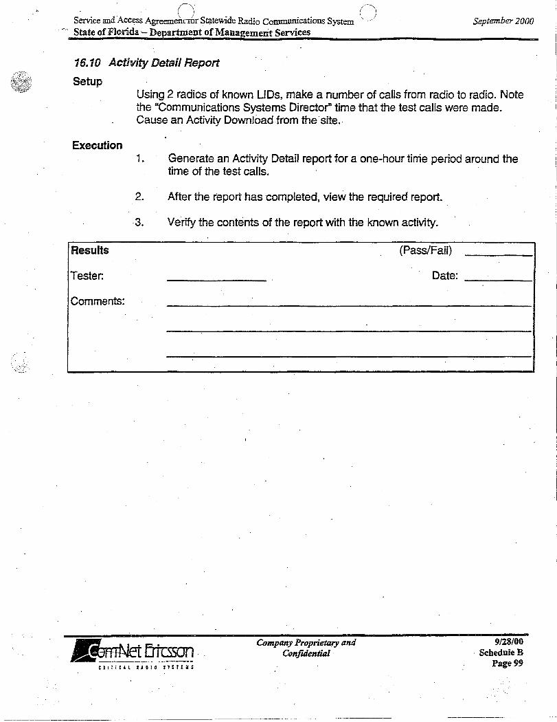
S~ce and Access AgreemDr Statewide Radio Communications System 0 ,,;-- State of Florida '- Department of Management Services
September 2000
16.10 Activity Detail Report
Setup
Execution
Results
Tester.
Comments:
Using 2 radios of known LIDs, make a number of calls from radio to radio. Note the "Communications Systems Director" time that the test calls were made. Cause an Activity Download from the'site.
1. Generate an Activity Detail report for a one-hour tinie period around the time of the test calls.
2. After the report has completed, view the required report.
·3. Verify the contents of the report with the known activity~
Company Proprietary and Confuiential
(Pass/Fail)
Date:
~ R I Tie, l I A ,0 lOS T S T £ II S
9128/00 . ScheduleB
Page 99

S · d'A () ~ . Ra· . . s r) emce an ccess Agreeu..~L1t ~or StateWIde 'clio Commurucatlons ystem" State of Florida - Department of Mana2ement Services
16.11 Activity Summary Report
Setup This test will use the activity generated in the previous test.
Execution
September 2000
1. Generate an Activity Summary report for a one-hour time period around, the time of the test calls.
Results
Tester:
Comments:
2. After the report has completed, view the required report.
3. Verify the contents of the report with the known activity.
Company Proprietary and Confidential
(Pass/Fail)
Date:
9/28/00 ScheduleB
Page 100'

Service and Access A~.at for Statewide Radio Communications Syst() State of Florida - Department of Management Services
16.12 Alarm'Report
Setup
September 2000
If an alarm was created in a previous test, use that" data for this test. If data is not available, create an alarm at the site noting the time of the condition.
Execution
Results
Tester:
Comments:
1. Generate an alarm report and enter the date/time for the created condition. Select the options required for type and complexity of report desired.
2. After the report is completed, view the completed report.
3. Verify the contents of the alarm report with the test aiarm.
(Pass/Fail)
Date:
~ I~ Ertt:sson .. ~~~~~~~ ___ ._ k.
Company Proprietary and Confidential
9/28/00 ScheduleD
Page 101 e. I : : t 1 l 1 J 0,1 0 $ T ; r EllS

Service and Access Agree(~) for Statewide Radio Communications SystenC) State of Florida - Department of Management Services
16.13 Channel Statistics Report
Setup
Sf!ptember 2000
This report displays activity per channel per hour and requires that some activity has OCcurred on each of the channels over a period of. sQme hours.
Execution 1. Generate an activity report for the period required.
2. After the report has been completed, view the report.
3. . Verify the contents of the report.
Results (Pass/Fail)
Tester: .. ",.,
Comments:
~ , ....... Ertcsson IIL,~~~~. ____ _
Company Proprietary and· ConjuJentia/
Date:
.'
9/28/00 ScheduleB
Page 102

.. : .. ~:: ...... ,
n (~'1 Service and Access Agreemen._.Jr Statewide Radio Communications System \ ./ State of Florida - Department of Management Services
16.14 Site Statistics Report
Setup
September 2000
This report displays activity statistics per site per hour and requires that some call activity has occurred over a period of some hours.
Execution 1. Generate a site activity report for the period required.
2. After the report has completed, view the report.
3. Verify the contents of the report.
Results
Tester:
Comments:
~~~ " WI.~11 -_ .. _. . . _...:_ .. - .. _--CII:!C4L RUIO ST~T£IIS
Company Proprietary and Confuiential
.. _-_ .. _---_._-------
(Pass/Fail)
Date:
9128/00 ScheduleB
Page 103
/.
~, . ~ r \ ( '\
Service and Access Agreer;. )for Statewide Radio Communications System,. ) State of Florida - Department of Management Services . -
September 2000
. 16.15 Dynamic Regroup
Setup
Execution
Ensure that Dynamic Regroup is a feature of the customer's radios. Ensure that both the· LIDs and the Regroup GIDs to be used are in the database and that the database has been successfully uploaded to site(s).
Tum off radio 1 and leave radio 2 on.
1. Select the Radio Controls Icon on the Desktop. If a Regroup Plan has not been created you must create one at this time.
. Highlight REGROUP PLANS. . Select EDIT from the Pull-down menu. Select ADD. Enter a name.
2. Enter the LID for radio 1.
3. Enter a GID in the Group Number column. Set its parameters to FORCED (Forces radio to group) and CAPTIVE (Does not allow radio to change groups).
4.
Select FI LE from the Pull-down menu and SAVE.
If a Members List has not been created, you must create one at this time. Highlight MEMBERS LIST. Select EDIT from the Pull-down Menu. Select ADD. Enter the name. Enter the LID to be modified and select ADD. Select the OPERATION tab and choose the appropriate selected plan. Click REGROUP.
5. Verify that the Current Radio Status column changes from NOT REGROUPED to REGROUP PENDING by selecting the PENDING REGROUPS tab. .
6. Tum radio 1 on. Verify that the Current Radio Status column changes from REGROUP PENDING to REGROUPED, and that the radio's regroup settings reflect the radio's current regroup status.
Company Proprietary and Confuiential
9128/00 Sch~uleB
Page 104

r ., "'-.: d i ) r. S . 'd . . S () .:x:;l Vice an Access Agreen._ .• c J.or tateWl e Radio Commumcatlons ystem / September 2000
State of Florida - Department of Management Services
Results
Tester:
Comments:
7. Perform the same actions for radio 2. Verify that the Current Radio Status column changes from NOT REGROUPED to REGROUPED and that the radiols regroup settings reflect the radiols current regroup status.
8, Verify that radios 1 & 2 can communicate on the regrouped group setting.
9. Turn radio 1 off and cancel ifs regrouping. Verify that the desired cancel operation is in process and that the Current Radio Status column changes from REGROUPED to CANCEL PENDING.
10. Tum radio 1 on. Verify that the Current Radio Status column changes from CANCEL PENDING to NOT REGROUPED, and that radio 1 will not communicate with radio 2. Verity that radio 1 has its original group fist.
11. Change the regroup plan for radio 2 back to ifs original settings and confirm that the radios can again communicate.
(Pass/Fail)
Date:
.
~ ',-rio Ertcsson "~~~~!~l._~_~. ___ ._
Company Proprietary and ConfuJential
9/28/00 ScheduleD·
Page 105

Service and Access Agre/-lt for Statewide Radio ~mmWlications Systcl") . "'--_/ . ~ ~~-' State of FIonda - Department of Management Services
talTitH 11010 $TUEIS
Company Proprietary and ConfuientiaI
September 2000
9128/00 ScheduleD
Page 106

(~ (",
Service and Access Agr~l.Llkt for Statewide Radio Communications Syst~) . State of Florida - Department of Management Services
17. RF COVERAGE
Acceptance Test Procedure Version: Last Modification Date:
State of Florida Rev. F July 18,2000
September 2000
This document describes in detail the RF Coverage Acceptance Test Plan (CATP) to be used by the State of Florida for RF coverage verification. This represents the performance verification process that the State of Florida will use to verify that the level of voice quality required by the Contract has been attained for radio communications in the required coverage service areas. The RF A TP is based on a Circuit Merit (Le., Digital Audio Quality for this ProVoice digital voice system and analog voice circuit merit) voice quality test for both portable and mobile radios communicating to another mobile/portable radio through base station repeater sites. The test procedure to be conducted is the same for both portable and mobile radio testing. However, separate testing will be conducted for portables and mobiles as the means of verifying minimum acceptable voice quality coverage in the different coverage service areas required for portable and mobile operation. A test method is specified for the Maritime and Aircraft coverage tests, which is "mobile" only.
17.1 Description of Test Method
Portable or mobile radio coverage is evaluated by logging the voice quality of test calls for a portable/mobile at specific test locations within the required service area and calculating the percentage of calls that meet or exceed the SOPs required voice quality criteria. At each test location, a test call is placed from the portable/mobile user to another mobile/portable located in a defined high-quality . coverage area (representing an inbound call), as well as from the test mobile/portable to the portable/mobile user (representing an outbound cal/).
Each test (inbound and outbound) will be performed up to three times, once for ProVoice'mode on the trunked radio system, once for analog voice mode on the trunked radio system, and once for analog voice mode on the conventional Mutual Aid sub-system. It is understood that during the Mutual Aid tests, a console operator will be required to enable and disable various Mutual Aid repeaters/simulcast clusters so that the appropriate sub-system is being used for the locations under test. If a Mutual Aid test fails, adjacent Mutual Aid subsystems will be used in repeats of the test for the failed grid. A successful test on any SUb-system shall cause the test grid to be considered a PASS for the mutual aid system.
The inbound and outbound test calls are graded at each test location using pass/fail criteria for both digital and analog signals. The Voice Quality Level 4 definition contained in Table 1 will serve as the pass criteria for all transmissions and will be called Defined Circuit Merit 4. .
CJITi'~l ItDI~ STllCIS
Company Proprietary and ConfuJentillJ
9128/00 ScheduleB
Page 107

(\ /'" I I I
Service and Access Agreeme~tI6i- Statewide Radio Communications System ... ./ September 2000 State of Florida - Department of Mana1Zement Services
Table 1. State of Florida Voice Quality Definitions·
Voice Quality Description Level
Speech completely clear and understandable. No discemable noise or 5 distortion beyond that of the strongest high quality radio signal. As good as it
.. gets. '.
4 Speech easily understood. Minor noise and distortion allowed if it does not affect the .inteHligibility of the messa~e. No audio _gaps. No repetition required. Speech understandable with slight effort, but occasional repetitions required.
3 Noticeable and persistent noise and distortion. Occasional short audio gaps of no more than a few syllables. Speech understandable with considerable effort, but frequent repetitions
2 required. Constant objectionable noise and distortion. Frequent audio gaps of up to several words.
1 Speech is not understandable. Noise, distortion and audio gaps completely mask useful intell~gibility.
17.2 Test Equipment and Preparation
The SOF supplies the mobile and portable radios used for the Delivered Audio Quality tests from inventory supplied as a part ofthe normal purchase of terminal eqUipment.
Prior to performing the tests, each-site must be audited to verify that the radio system is 'operating properly. The portions of the radio system requiring audits and the equipment required t9 perform the audits are: (i) the transmit frequency using a frequency counter, (ii) the power into the antenna system using a power.
. meter, and (iii) the antenna installation using a frequency-domain reflectometer (FOR). Com-Net Ericsson will also audit the mobile and portable equipment supplied by the SOF. Com-Net Ericsson shall provide all test equipment, with current calibration certification, necessary to perform the site audits. Additionally, the drive route is determined by mutual agreement between the SOF and Com-Net Ericsson, documented on maps, and supplied to the drive test team(s).
17.3 Test Location Planning
A drive route plan.is developed to gather a collection of data pOints evenly distributed throughout the defined service area and provide a statistically accurate determination of radio coverage performance. .
Dividing the service .area into equally sized grids is an aid to drive· route planning . and to ensure statistical validity of the distribution of test data. The service area . .
C I I Tit A l I' ~ IDS y. S I £ H :
Company Proprietary and Confuiential
9128/00 ScheduleR
Page 108

(~. -" , r Service and Access AgreeIli~_jfor Statewide Radio Communications System j September 2000 State of Florida - Department of Management Services
will be divided into one mile by one mile square grids to obtain a uniform distribution of grids. Com-Net Ericsson will provide an automated grid location device. This device will make use of a GPS receiver and pre-programmed grid· and provide an indication to the test operators when a new test grid has been physically entered during the course of the drive route. The test operators will, upon the indication event, perform the required tests for that grid. All test calls for portable radios will initially be conducted in a moving test vehicle. If that test fails, the test will be conducted again with the portable radio helq at head;.height level, and the portable operator at street level outside any vehicle or other enclosure such as buildings, tunnels or underground garages.
All test calls for portable radio testing will be" made using a one-quarter wave flexible antenna (non-elevated feed, as will be typically installed).
All test calls for mobile radio testing will be made using a 3 dB omni-directional gain antenna (non-elevated feed, as will be typically installed) located on the center trunk, with the mobile vehicle at street level and outside any enclosures such as buildings, tunnels or underground garages.
Any grid not tested, at the election of SOF, will be disregarded in the data analYSiS, and will not contribute to the total number of grids tested. .
17.4 Grading of Test Locations
The test requires two SOF Customer representatives to perform the grading, and" two additional SOF Customer representatives to serve as alternate judges. ComNet Ericsson will provide two test observers. One SOF Customer representative travels the drive route and grades the ou~bound calls at each test location, accompanied by a Com-Net observer. The remaining grader resides at the test mobile/portable location and grades the inbound calls, accompanied by a ComNet ob$erver. Each of the two SOF CustomeOr representatives marks the test score for each test location using the template in Table 2. PASS or FAIL' determination is made separately for the inbound and outbound calls in each grid, so that it is possible for a call to PASS in one direction but FAIL the other.
In the event that the Com-Net observer disputes the grade given by the SOF Customer representative for a particular location, he/she may request that the disputed test be evaluated by the other SOF Customer representative. If the grades dIffer, both grades will be recorded for subsequent review and arbitration. To facilitate the second evaluation, each voice test shall ~e recorded by the test team; the subsequent review will be made usi"ng the recorded test message.
The test message consists of a short message of length not exceeding ten seconds and includes the identification of the location being tested. The
~ f~ Erttsson "'~.!1~~~_ .. _. _______ ~
Company Proprietary and ConfUiential
9/28/00 ScheduleB
Page 109

\.,
;'~. - ( Service and Access Agreemel .... br Statewide Radio Communications System \, )
State of Florida - Department of Management Services September 2000
c.
suggested inbound test message is "GRID XXX," and a short, pseudo-random sequence of numbers or common words-as a unique test phrase; where XXX is the grid number. This inbound test call is then acknowledged by the test mobile/portable operator by an outbound test call such as "GRID XXX," another test phrase, and "END OF TEST", where XXX is the grid number.
The mobile tests shall be conducted with the vehicle traveling at the prevailing speed on the road under test. A portable test attempt shall immediately follow the mobile test, with the portable being held at face level inside the moving test vehicle. It is understood that if the attempted portable test, in the moving vehicle, is a PASS, then it would have been a.PASS if conducted while stationary outside the vehicle. If the portable test attempt fails, then the vehicle will be stopped and the portable test will be conducted as described in Para. 1.3 of this procedure. The purpose of this "attempted" test is to make efficient use of test resources.
For each call direction, a test location is deemed to PASS if it meets the requirements for the agre~d-upon definition of Defined Circuit Merit 4 recovered voice quality level, or better, from the SOF grader. If the grader determines the analog or digital transmission does not meet the prescribed level, then -that test location fails for the direction being graded.
17.5 Data Analysis and Acceptance
The data logged by the two representatives on the grading template of Table 2 is then analyzed to determine the percentage of test locations that meet the Defined Circuit Merit 4 qual1ty criterion.
The installed' radio system coverage is deemed to meet the percent service area coverage guarantees offered by Com-Net Ericsson to the State of Florida if the following conditions are met for each of the modes of test, ProVoice digital trunked, analog voice trunked and analog conventional (Mutual Aid): i
Mobile State-wide Coverage
1. The number of PASS grids must equal or exceed 98% of the total number of grids tested. The corresponding inbound and outbound calls must both PASS for the grid to PASS.
2. Failed grids shall not be clustered greater than defined window requirements. The sliding window shall be defined as 30 miles by 30 miles in size. The window may be placed anywhere in the State of Florida defined coverage area and shall include whole grids. -If more than 5 percent of the grids in any placement of the sliding window FAIL, then the State will consider the coverage test to have failed.
~!"fl- Erfcsson "~!.~L .~_._ .. _____ .
Company Proprietary and Confidential
9/28/00 ScheduleB
Page 110 CUTICH .ADID SYSTEM:

~\ r"· Service and Access Agreel .... t for Statewide Radio Communications Systen:.. / State of Florida - Department of Management Services ..
September 2000
Portable Service Area Coverage
1. The number of PASS grids must equal or exceed 98% of the total number of grids tested. The corresponding inbound and outbOund calls must both PASS for the grid to PASS.
2. All defined portable areas will be tested for 98% coverage. 98% coverage . must be independently achieved for each of the defined test areas. Each contiguous area that crosses a boundary between the current State of Florida phases will be split according to those boundaries and tested independently. Each contiguous area tested must have a minimum of 200 grids and a maximum square grid size of one mile by one mile. For the defined areas of less than 200 square miles, an appropriate grid size will be chosen to ensure that at least 200 grids ·can be tested. .
It is understood that the trunked radio system will be exhaustively tested, mobile, and portable, inbound and outbound, in the ProVoice trunked mode, i.e: all available grid squares that are deemed accessible by the SOF will be tested. It is further understood that the analog trunked and analog conventional (Mutual Aid) tests may be conducted until the SOF may determine that their coverages are equivalent or better than ProVoice trunked mode. At the point of this determination, the SOF may elect to deem those test modes as having passed, and accept the total system solely based on the results of the ProVoice trunked testing.
17.6 Maritime Distance Testing
The Maritime Distance test shall be conduqted in a "mobile" manner using the normal boat radio installed as typical for a boat installation. SOF and Com-Net Ericsson will mutually agree that the antenna mount configuration provides a, fair evaluation qf coverage and is not biased in any particular azimuth.
The 25-mile offshore coverage distance requirement will be .tested separately by performing a coverage test on a sea route equidistant between the nearest two base radio-transmitting sites until a distance 25 miles from the shore is reached. The individual voice quality tests shall be performed at one-mile intervals along this route. If there is more than one failure 'along the path until the 25-mile mark is reached, the test will be determined as a failure. This test may be repeated between all sets of base transmitting locations nearest the shore or may be omitted on an individual basis as determined by the SOF. The Maritime Distance tests shall be conducted in each of three modes, ProVoice trunked, analog voice trunked and analog conventional-(Mutual Aid). The SOF may elect to omit either or both of the analog mode tests. Omitted tests shall be considered as having been. successfully passed. .
Company Proprietary and . Confidential
9128/00 ScheduleB·
Page 111

Service and Access Ar:ent for Statewide Radio Communications s~\ State of Florida - D~artment of Management Services
17.7 Aircraft Coverage Testing
September 2000 I,
The Aircraft Coverage test shall be conducted in a "mobile" manner using the normal aircraft radio installed as typical for an aircraft installation. SOF and ComNet Ericsson will mutually agree that the antenna mount configuration provides a fair evaluation of coverage and is not biased in any particular azimuth.
The aircraft test routes shall be normal flight plans provided by four SOF entities, FHP, FDLE and FWCC (inland and coastal). For each aircraft site, one fixed wing aircraft and one rotary aircraft flight plan will be flown by each entity. Individual tests shall be performed along the flight plan routes at one-minute intervals, as closely as practical. The SOF may eject to omit any of the defined flight plans. All voice tests performed in an aircraft while on the ground shall be conducted using the mobile/portable coverage sites of the system. Tests conducted while the aircraft is in the air shall be conducted using the aircraft coverage sites of the system.
The Aircraft Coverage tests shall be conducted in each of three modes, ProVoice trunked, analog voice trunked and analog conventional (Mutual Aid). The SOF may elect to omit either or both of the analog mode tests. Omitted tests shall be considered as having been passed.
The number of PASS calls statewide must equal or exceed 98% of the total number of calls. The corresponding inbound and outbound calls must both PASS for the call to PASS.
'17.8 Results Presentation
A test report is provided that includes an indication of the test point locations; a copy of the Table 2 grading template for each grader; the percentage pass calculation for the total number of grids tested for each test mode; and statement of the overall test acceptance or failure.
~ I~ Ertcsson IJL~-'!~ .. ~. .._. ___ .
CI"!ClL HDID STlTEI:
Company Proprietary and Confidential
9128/00 ScheduleD
Page 112

/~
Service and Access AgreemeJ. _.J~ Statewide Radio Communications System State of Florida - Department of Management Services
September 2000
Table 2: Voice Circuit Merit Coverage Test Grading Template Check the link used: 0 Portable Inbound 0 Mobile Inbound
o Portable Outbound . 0 Mobile OutboUnd
Coverage Circuit Merit Coverage Test Data for State of Florida Date·
State of Florida Evaluator: State of Florida Second Evaluator: Com-Net Observer:
Fixed Test Mobile!Portable Location: Test Radio Serial numbers:
Grid No. Pro Voice tnmked Analog trunked Mutual Aid Remarks analog
conventional
(Etc...... One row for each test locatIon)
Note: If a second eval.uation is requested, use a second line repeating the grid number, and note the request in the Remarks field.
~ I.-r+- ErtcS50n "'~f.~~~~~ ... __ .. ~. __ ... _
Cll'ICAL RADIO STSTEIIS
Company Proprietary and Confidential
9128/00 ScbeduleB
Page 113
.. -.--.-------.-~------------.---.-----~-~ .. --

· r"\ r' Service and Access AgreemJ .... __ or Statewide Radio Communications Syste~ , ) September 2000 State of Florida. - Department of Management Services
18. Non-Interference Verification
To verify the co-channel and adjacent channel interference performance of the 800 MHz ProVoice EDACS network, 2 to 3 pairs of sites with the same' frequencies will be chosen within each Phase (or with a prior Phase) for 'Verification of non-co-channel interference. Two to 3 pairs per Phase will also be tested for adjacent channel conditions between each pair of sites. The tests will be conducted after installation but prior to ,placing users in operation on the sites.
For descriptive purposes, the two sites under test are referred to as System A and System B. The test will be conducted as follows:
A mobile radio, normally installed in a SOF. vehicle, will be operated on System B 'frequencies. The vehicle will be located within the normal coverage area of System B, at a point of closest approach to the site for System A. The mobile will drive a racetrack or similar pattern of approximate'ly V2 mile in length during the test, perpendicular to the line towards the site for System A..
A portable radio will be operated on the frequencies for System A. The portabfe will be operated handheld, outdoors, within the normal coverage area of System A, but at a distance removed from the site approximately at the limit of expected coverage of System A.
The locations for the mobile and portable radios during the test will be mutually agreed, prior to testing, between Com-Net'Ericsson and the State of Florida.
A normal group call will be placed by the portable on System A. A normal group call will be placed by the mobile pn System B. The test operators will ensure that the frequencies in use during the test are either co-channel or adjacent channel, depending on the test being conducted.
The test will be conducted for a: reasonable amount of time, with the mobile radio moving through its test location pattern and the portable radio being moved through a small area (10 to 20 feet). The test operators will determine wh~ther the mobile radio call is destructively interfering with the portable radio call.
Any cases of interference observed by the test operators will be documented, and reviewed with the, SOF. Observed cases of minor interference will not necessarily .delay implementation or acceptance of the Phase or Phase segment, but will result in notations of an open item that shall be resolved, if feasible, prior to overall system final acceptance, with a schedule to be mutually agreed. It is anticipated that the scope of the resolution of 'such observed interference cases will be alteration of antenna patterns and similar items.
ClI,i:ll RADIO SYSTEMS
Company Proprietary and Confidential
9128/00 ScheduleB
Page 114
!
I -------------------------... ----.. -.. ------------ --------------.--_._-.. ----. __________________ ~. _____ . ______ . ___________ . ____ . _____ . _________________ . ______________ .i

· n r" Service and Access Agreemt..jfor Statewide Radio Communications System- ) September 2000 State of Florida -:- Department of Management Services
Cases of major interference will be resolved prior to acceptance of that Phase or Phase segment. .
~ I,,""" Ertcsson .1J1I.~~.!~l_ . ' .... _____ ~
CRI!IClL lUI.O $.TsrEI~
--~ ------- ----------------~--- -----~~-~~~
Company Proprietary and Confidential
9/28/00 ScheduleB
Page 115

Service and Access AgreemdJ Statewide Radio Communications System r\ State of Florida - Department of Management Services \, j
19. Other Acc~ptance Tests
September 2000
Other acceptance tests may be performed if mutually agreed upon by the parties prior to beginning any such. test.
~ I;-ri- Erfr:sson ... ~~~~~!~-~-. -.. ~-
C I I r ! c .4 L R' 0 I OS T $ T £ II $
Company Proprietary and Confidential
9128/00 ScheduleB
Page 116