Embed Size (px)
Citation preview

International Association
Of Certified
Practicing Engineers
www.iacpe.com
Achieving Your Potential Education Certification Networking
Page : 1 of 155
Rev: 01
Rev 01 Nov 2015
IACPE
No 19, Jalan Bilal Mahmood 80100 Johor Bahru Malaysia
Piping Fluid Flow Material
Selection and Hydraulic Line Sizing, Two Phase Flow, and Surge
CPE LEVEL II
TRAINING MODULE
The International Association of Certified Practicing Engineers is providing the introduction to the Training Module for your review. We believe you should consider joining our Association and becoming a Certified Practicing Engineer. This would be a great option for engineering improvement, certification and networking. This would help your career by
1. Providing a standard of professional competence in the practicing engineering and management field
2. Identify and recognize those individuals who, by studying and passing an examination, meets the standards of the organization
3. Encourage practicing engineers and management professionals to participate in a continuing program of personal and professional development
www.IACPE.com
International Association
Of Certified
Practicing Engineers
Piping Fluid Flow Material Selection and Hydraulic Line Sizing,
Two Phase Flow, and Surge
CPE LEVEL II TRAINING MODULE
Page 2 of 155
Rev: 01
Nov 2015
TABLE OF CONTENT
INTRODUCTION Scope 5
General Design Consideration 6
DEFINITIONS 29 NOMENCLATURE 35 THEORY OF THE DESIGN 39 A. Physical Properties of Fluids 39 B. Single Phase Flow Characteristic in Pipe 43
1. Reynolds Number 43
2. Fluid Flow Equations for the Friction Loss/Pressure Drop in Pipe 44
3. Straight Line Pressure Drop 46
4. Effect of Valve, Fitting on Pressure Drop 47
5. Enlargements and Contraction Pipe Line Pressure Drops Calculation 48
6. Nozzles and Orifices 50
7. Line Sizing 51
i. Design Procedure for In-Compressible Flow 52
ii. Design Procedure for Compressible Flow 53
International Association
Of Certified
Practicing Engineers
Piping Fluid Flow Material Selection and Hydraulic Line Sizing,
Two Phase Flow, and Surge
CPE LEVEL II TRAINING MODULE
Page 3 of 155
Rev: 01
Nov 2015
C. Two Phase Flow Characteristic 57 1. Flow Regime 58
2. Two Phase Pressure Drop 65
3. Two Phase in Perforated Pipe Distributors 78
4. Flashing Critical Flow 79
5. Distribution Manifolds 83
D. Hydraulic Surge 85 1. Moment Inertia 91
2. Wavespeed inside Pipe 93
3. Valve Stroking Time 96
4. Surge Pressure 98
E. Piping Fluid Flow Material Selection 109 F. Pump Suction Piping 111
APPLICATION Example Case 1: In-Compressible flow with Water 119
Example Case 2: In-Compressible flow with HC 122
Example Case 3: Compressible flow with Steam 125
Example Case 4: Compressible flow with Natural Gas 128
Example Case 5: Pump suction 131
Example Case 6: Two Phase Pressure Drop and Flow Pattern in Horizontal Pipe 133
Example Case 7: Two Phase Pressure Drop and Flow Pattern in Vertical Pipe 142
Example Case 8: Liquid Surge Calculation Using Joukowsky Equation 153
Example Case 9: Liquid Surge Calculation Using Allievi charts 154
International Association
Of Certified
Practicing Engineers
Piping Fluid Flow Material Selection and Hydraulic Line Sizing,
Two Phase Flow, and Surge
CPE LEVEL II TRAINING MODULE
Page 4 of 155
Rev: 01
Nov 2015
REFEREENCES 156 LIST OF TABLE Table 1 : General Pipe Material Roughness 46
Table 2a: Example of the equivalent lengths for various kinds of fittings 48
Table 2b: Friction factor for the commercial steel pipe 48
Table 3 : Pipe velocities and allowable pressure drops for various fluids 51
Table 4 : Optimum velocity for various fluid densities 51
Table 5 : Reasonable Velocities for flow of water/fluid with almost same density through pipe 53
Table 6 : Reasonable Velocities for flow of steam through pipe 56
Table 7 : The appropriate values to use 73
Table 8 : Beggs and Brill holdup contants 77
Table 9 : Velocity range for two phase flow 78
Table 10: Density and bulk modulus some liquid 94
Table 11: Modulus young for some material of pipe 95
Table 12: The effect of gas content to wavespeed 96
Table 13: Major Countermeasures for Liquid Surge Problems (Up-Surge) 105
Table 14: Major Countermeasures for Liquid Surge Problems (Down-Surge) 106
Table 15: Primary attributes and design variables of key surge-protection approaches 107
Table 16: lists the parameter choice in the conservative modelling approach. 108
Table 17: Guideline for the Piping Fitting and Pipe Material Selection. 109
Table 18 . Vapor pressure (VP) versus temperature for water. 116
International Association
Of Certified
Practicing Engineers
Piping Fluid Flow Material Selection and Hydraulic Line Sizing,
Two Phase Flow, and Surge
CPE LEVEL II TRAINING MODULE
Page 5 of 155
Rev: 01
Nov 2015
LIST OF FIGURE Figure 1: Flow regime in horizontal pipeline; (a). Bubble flow, (b) Plug flow, (c) Stratified flow, (d) Wafy flow, (e) Slug flow, (f) Annular flow, and (g) Spray flow 13
Figure 2: Flow regime in vertical pipeline; (a). Bubble flow, (b) Slug flow, (c) Froth flow, (d) Annular flow, (e) Mist flow 15
Figure 3: (a) an impacting tee and (b) a straight-through tee 16
Figure 4: Water Hammer Description 19
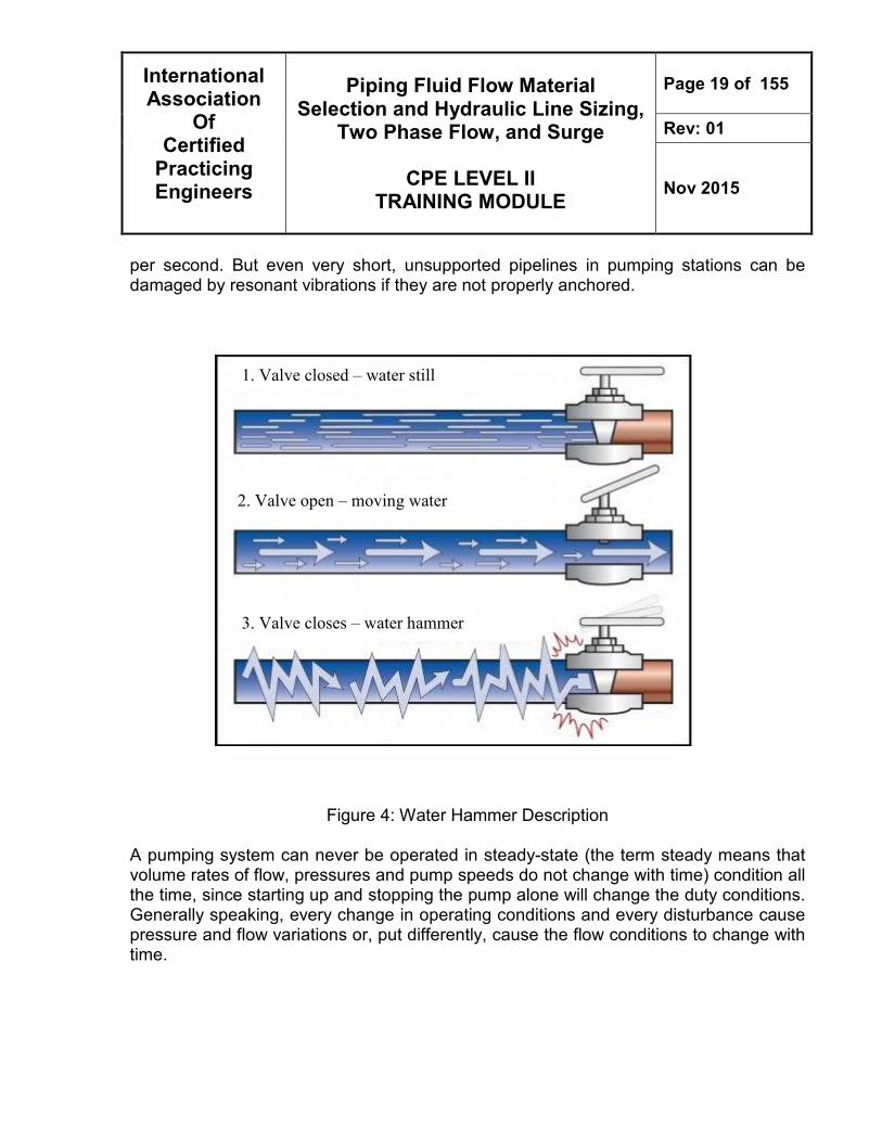
Figure 5: Steady-state pressure head curve of a pumping system 21
Figure 6: The different maximum subpressures due to different pipe profiles. 23
Figure 7: Macro-cavitation following pump trip 25
Figure 8: Different effects of a weakened section 28.
Figure 9 : a. Sudden/ Gradually Enlargement b. Sudden/ Gradually Contraction 48
Figure 10: Two-Phase Flow Regimes In Horizontal Pipe 60
Figure 11: Two-Phase Flow Regimes In Vertical Pipe 63
Figure 12: Liquid Holdup Correlation for Vertical Pipe 67
Figure 13: Critical Flow Of Vapor - Liquid Mixtures 82
Figure 14: Manifold Designs For Distributing Two-Phase Flow 84
Figure 15: Flowchart for surge control in water distribution systems (AWWA, 2005) 89
Figure 16: Guide to selection of components for the transient control (Thorley, 1991) 90
Figure 17: Estimating the effective valve stroking time Te 98
Figure 18: Allievi Chart 103
Figure 19: Centrifugal pump with semi-open impeller 118
International Association
Of Certified
Practicing Engineers
Piping Fluid Flow Material Selection and Hydraulic Line Sizing,
Two Phase Flow, and Surge
CPE LEVEL II TRAINING MODULE
Page 6 of 155
Rev: 01
Nov 2015
INTRODUCTION Scope This training module covers the basic elements in the field of Piping Fluid Flow Material Selection and Hydraulic Line Sizing in sufficient detail to design a pipeline. Pipe size is determined by the length of the pipe and the allowable pressure drop in the line. The allowable pressure drop may be influenced by factors, including process requirements, economics, safety, and noise or vibration limitations. This guideline also covers piping related equipment, such as valve, fittings and orifices. Pressure drop calculations in these fitting are discussed in detail to help for the sizing for liquid and gas phase fluids.
Fluid phases can be considered as pure liquid or pure gas phases. In this guideline, these differences phases were discussed in detail for the engineering design for the laminar and turbulence flow and for various substances of fluids, for example, water, steam and hydrocarbon. The theory section covers the selection method of the piping material based on their application and engineering calculations for the sizing of the piping.
In the application section of this guideline, four case studies are shown and discussed in detail, highlighting the way to apply the theory for the calculation. Generally used theory, such as Bernoulli’s theory, is used as the basic of calculation because it is applicable for various conditions. The case studies will assist the engineer perform the selection and sizing for the piping based on their own plant system.
International Association
Of Certified
Practicing Engineers
Piping Fluid Flow Material Selection and Hydraulic Line Sizing,
Two Phase Flow, and Surge
CPE LEVEL II TRAINING MODULE
Page 7 of 155
Rev: 01
Nov 2015
General Design Consideration
In designing the piping fluid flow there are many factors have to be considered for the suitability of the material selection for the application codes and standards, environmental requirements, safety, performance of the requirements, and the economics of the design and other parameters which may constrain the work. They should be included engineering calculations for the piping system design. Combined with the piping design criteria, calculations define the process flow rates, system pressure and temperature, pipe wall thickness, and stress and pipe support requirements. The service conditions should be the consideration as well because the piping system is designed to accommodate all combinations of loading situations such as pressure changes, temperature changes, thermal expansion and contraction and other forces or moments that may occur simultaneously and they are used to set the stress limit of the design. Design code and the standards are reviewed for the project of the design for the safety purposes and the verification of the applicability. In this design guideline generally follows the codes and the standards of the American Society of Mechanical Engineers (ASME) Code for Pressure Piping, B31. ASME B31 includes the minimum design requirements for various pressure piping applications.(4)
Normal environmental factors that have the potential for damage due to corrosion must be addressed in the design of process piping. Physical damage may also occur due to credible operational and natural phenomena, such as fires, earthquakes, winds, snow or ice loading, and subsidence. Two instances of temperature changes must be considered as a minimum. First, there are daily and seasonal changes. Second, thermal expansion where elevated liquid temperatures are used must be accommodated. Compensation for the resulting expansions contractions are made in both the piping system and support systems. Internal wear and erosion also pose unseen hazards that can result in system failures.
Most failures of fluid process systems occur at or within interconnect points the piping, flanges, valves, fittings, etc. It is, therefore, vital to select interconnecting equipment and materials that are compatible with each other and the expected environment. Materials selection is an optimization process, and the material selected for an application must
International Association
Of Certified
Practicing Engineers
Piping Fluid Flow Material Selection and Hydraulic Line Sizing,
Two Phase Flow, and Surge
CPE LEVEL II TRAINING MODULE
Page 8 of 155
Rev: 01
Nov 2015
be chosen for the sum of its properties. That is, the selected material may not rank first in each evaluation category; it should, however, be the best overall choice. Considerations include cost and availability. Key evaluation factors are strength, ductility, toughness, and corrosion resistance. Piping material is selected by optimizing the basis of design. The remaining materials are evaluated for advantages and disadvantages such as capital, fabrication and installation costs; support system complexity; compatibility to handle thermal cycling; and catholic protection requirements. The highest ranked material of construction is then selected. The design proceeds with pipe sizing, pressure integrity calculations and stress analyses. If the selected piping material does not meet those requirements, then second ranked material is used to sizing, pressure integrity calculation and stress analyses are repeated. For the pressure drop calculation: the primary requirement of the design is to find an inside diameter with system design flow rates and pressure drops. The design flow rates are based on system demands that are normally established in the process design phase of a project. This will involves trial and error procedure to find the suitable inside diameter. Basically service conditions must be reviewed to determine operational requirements such as recommended fluid velocity for the application and liquid characteristics such as viscosity, temperature, suspended solids concentration, solids density and settling velocity, abrasiveness and corrosively. This information is useful to determine the minimum internal diameter of the pipe for the whole system network. Normal liquid service applications, the acceptable velocity in pipes is 2.1 ± 0.9 m/s (7 ± 3 ft/s) with a maximum velocity limited to 2.1 m/s (7 ft/s) at piping discharge points including lines and drains. This velocity range is considered reasonable for normal applications.(4) Pressure drops throughout the piping network are designed to provide an optimum balance between the installed cost of the piping system and operating costs of the system pumps. Primary factors that will impact these costs and system operating performance are internal pipe diameter (and the resulting fluid velocity), materials of construction and pipe routing.
International Association
Of Certified
Practicing Engineers
Piping Fluid Flow Material Selection and Hydraulic Line Sizing,
Two Phase Flow, and Surge
CPE LEVEL II TRAINING MODULE
Page 9 of 155
Rev: 01
Nov 2015
Single Phase Flow Pressure drop, or head loss, is caused by friction between the pipe wall and the fluid, and by minor losses such as flow obstructions, changes in direction, changes in flow area, etc. Fluid head loss is added to elevation changes to determine pump requirements. A common method for calculating pressure drop is the Darcy-Weisbach equation. Normally for the line sizing the following rules should be follow
1) Calculate the Pressure drop with expressed in the term “psi/100 ft of pipe”. 2) Select the suitable Velocity which expressed in ft/sec; there is standard for
general liquid flow the range of the velocity should be in the suitable range for the basic design.
3) Calculate the Reynolds number to determine the fluid flow. Reynolds number is a
factor of pipe diameter, flow rate, density, and viscosity of the liquid; allows analysis of flow characteristics (slug, laminar, transition, turbulent); sanitary systems always require full turbulence (Reynolds number > 10,000)
4) Determine the suitable of pipe diameter - the inside pipe or tube diameter is used
in the several equations to determine the pressure drops, Reynolds number, velocity and etc.
5) Determine the roughness of pipe, the more rough the pipe, the larger the friction
factor; the larger the friction factor, the more pressure drop. 6) Incompressible flow - liquids; actual pressure is not a factor in pressure drop
calculation. 7) Compressible flow - gases and vapors; actual pressure is a direct factor in
pressure drop calculation.
Liquids (Incompressible Flow): Size longer lines for less pressure drop than shorter lines. Most water-like liquids, long lines should be sized for 0.5 to 1.0 psi/100 ft; short
lines should be sized for 1.0 to 2.0 psi/100 ft; but there are no hard and fast rules.
International Association
Of Certified
Practicing Engineers
Piping Fluid Flow Material Selection and Hydraulic Line Sizing,
Two Phase Flow, and Surge
CPE LEVEL II TRAINING MODULE
Page 10 of 155
Rev: 01
Nov 2015
For liquids with viscosities 10 cp or less consider just like water; above 10 cp, check Reynolds number to see what equations to use for pressure drop calculation. Careful with sizing lines in the fractional line size range; It may cost more to install ¾” pipe and smaller than 1” pipe due to support requirements. Usually don’t save on header sizing to allow for future increase in capacity without changing out pipe. Pipeline holdup of process liquids may be a factor; smaller pipe may be desired to limit holdup even though pressure drop goes up. Gases and Vapors (Compressible Flow): Supply pressure is a major factor in line sizing calculations; also, overall pressure drop by means of typical calculation methods should not exceed 10% of the supply pressure, otherwise, alternative calculation methods must be used. Typically, consider all gases and vapors (including saturated steam) to behave gases in order to calculate vapor densities (PV = nRT). Two Phase Flow Two-phase flow presents several design and operational difficulties not present in single phase liquid or vapor flow. Frictional pressure drops are much harder to calculate. For cross-country pipelines, a terrain profile is needed to calculate elevation pressure drops. For two phase, the respective distributions of the liquid and vapor phases in the flow channel is important aspect of their description. Their respective distribution take on some commonly observed flow structures, which are defined as two phase flow patterns that have particular identifying characteristics. Heat transfer coefficients and pressure drops are closely related to the local two phase flow structure of the fluid, and thus two phase pattern prediction is an important aspect of modeling evaporation and condensation.
In two-phase flow, interactions between liquid and vapor phases, as influenced by their physical properties and flow rates and by the size, roughness and orientation of the pipe, cause the fluids to flow in various types of patterns. These patterns are called flow regimes. Only one type of flow exists at a given point in a line at any given time. However, as flow conditions change, the flow regime may change from one type to another. In flow of mixtures of the two phases in pipelines, the liquid tends to wet the wall and the gas to concentrate in the center of the channel, but various degrees of dispersion of
International Association
Of Certified
Practicing Engineers
Piping Fluid Flow Material Selection and Hydraulic Line Sizing,
Two Phase Flow, and Surge
CPE LEVEL II TRAINING MODULE
Page 11 of 155
Rev: 01
Nov 2015
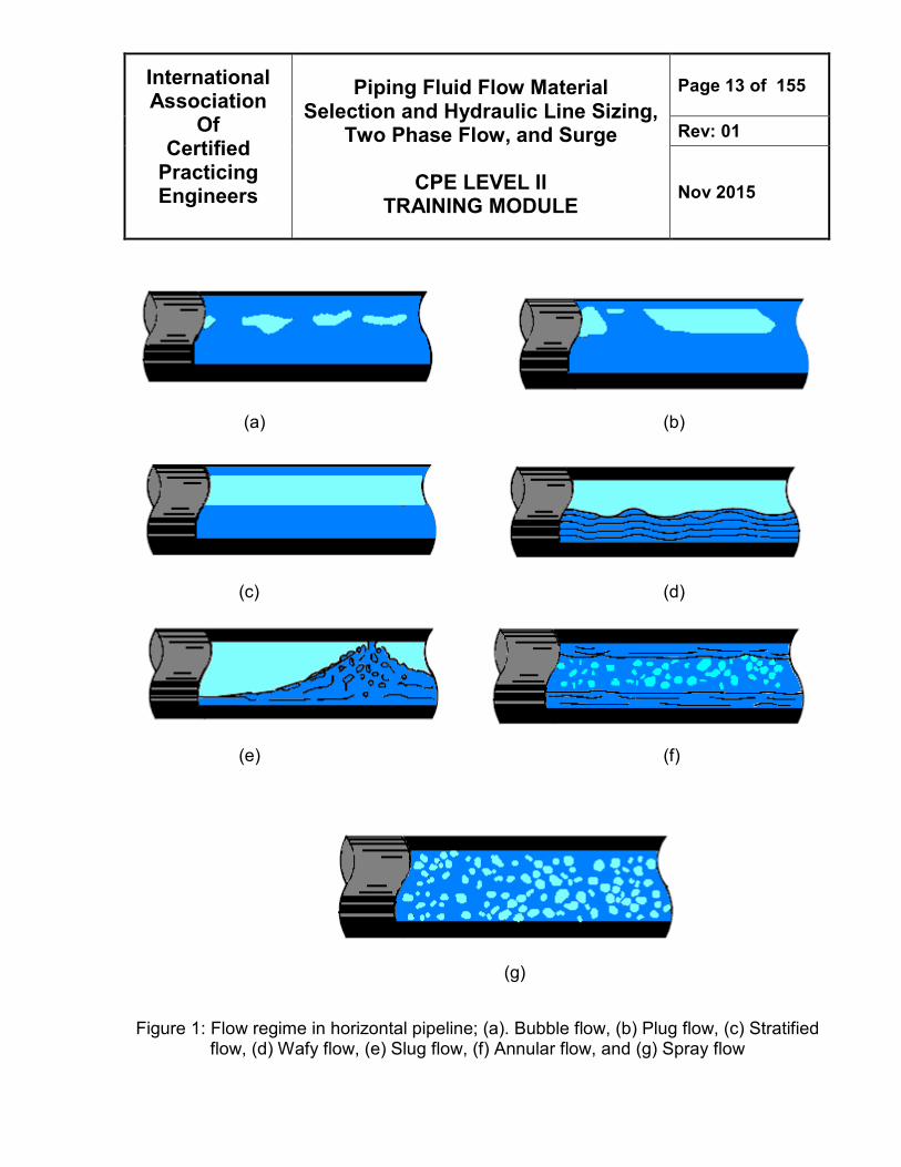
each phase in the other may exist, depending on operating conditions, particularly the individual flow rates Seven principal flow regimes have been defined to describe flow found in horizontal or slightly inclined pipes. These flow regimes are described below, in order of increasing vapor velocity. In the accompanying sketches, the direction of flow is from left to right. 1. Bubble Flow
Liquid occupies the bulk of the cross-section and vapor flows in the form of bubbles along the top of the pipe. Vapor and liquid velocities are approximately equal. If the bubbles become dispersed throughout the liquid, this is sometimes called froth flow. In uphill flow bubbles retain their identity over a wider range of conditions. In downhill flow the behavior is displaced in the direction of plug flow. Bubble flow is of importance to the chemical process industry, where the rise of bubbles through a liquid, both individually and in swarms (clusters), has received considerable attention. Properly speaking, bubbly flow is not a fully developed flow regime because given enough time or distance, the bubbles may collide with each other; and their agglomeration could lead to the formation of large bubbles or slug flow. In some instances, where proper care is taken in their generation, the bubbles present in the stream are small enough that they will touch rarely, and bubble flow will persist for a significant distance.
2. Plug Flow
As the vapor rate increases, the bubbles coalesce, and alternating plugs of vapor and liquid flow along the top of the pipe with liquid remaining the continuous phase along the bottom. In an uphill orientation, the behavior is displaced in the direction of bubble flow; downhill, stratified flow is favored.
3. Stratified Flow
As the vapor rate continues to increase, the plugs become a continuous phase. Vapor flows along the top of the pipe and liquid flows along the bottom. The interface between phases is relatively smooth and the fraction occupied by each phase remains constant. In uphill flow, stratified flow rarely occurs with wavy flow being favored. Downhill, stratified flow is somewhat enhanced, as long as the inclination is not too steep.
4. Wavy Flow
International Association
Of Certified
Practicing Engineers
Piping Fluid Flow Material Selection and Hydraulic Line Sizing,
Two Phase Flow, and Surge
CPE LEVEL II TRAINING MODULE
Page 12 of 155
Rev: 01
Nov 2015
As the vapor rate increases still further, the vapor moves appreciably faster than the liquid and the resulting friction at the interface forms liquid waves. The wave amplitude increases with increasing vapor rate. Wavy flow can occur uphill, but over a narrower range of conditions than in a horizontal pipe. Downhill, the waves are milder for a given vapor rate and the transition to slug flow, if it occurs at all, takes place at higher vapor rates than in horizontal pipes.
5. Slug Flow
When the vapor rate reaches a certain critical value, the crests of the liquid waves touch the top of the pipe and form frothy slugs. The velocity of these slugs, and that of the alternating vapor slugs, is greater than the average liquid velocity. In the body of a vapor slug the liquid level is depressed so that vapor occupies a large part of the flow area at that point. Uphill, slug flow is initiated at lower vapor rates than in horizontal pipe. Downhill, it takes higher vapor rates to establish slug flow than in horizontal pipe, and the behavior is displaced in the direction of annular flow. Slug flow should be avoided where possible because it may lead to pulsation and vibration in bends, valves and other flow restrictions.
6. Annular Flow
The liquid flows as an annular film of varying thickness along the wall, while the vapor flows as a high-speed core down the middle. There is a great deal of slip between phases. Part of the liquid is sheared off from the film by the vapor and is carried along in the core as entrained droplets. At the same time, turbulent eddies in the vapor deposit droplets on the liquid film. The annular film on the wall is thicker at the bottom of the pipe than at the top, the difference decreasing with distance from slug flow conditions.
Downstream of bends, most of the liquid will be at the outer wall. In annular flow, the effects of friction pressure drop and momentum outweigh the effect of gravity, so that pipe orientation and direction of flow have less influence than in the previous flow regimes. Annular flow is a very stable flow regime. For this reason and because vapor-liquid mass transfer is favored, this flow regime is advantageous for some chemical reactions.
7. Spray Flow (Mist Flow or Dispersed Flow)
When the vapor velocity in annular flow becomes high enough, all of the liquid film is torn away from the wall and is carried by the vapor as entrained droplets. This flow regime is almost completely independent of pipe orientation or direction of flow.
International Association
Of Certified
Practicing Engineers
Piping Fluid Flow Material Selection and Hydraulic Line Sizing,
Two Phase Flow, and Surge
CPE LEVEL II TRAINING MODULE
Page 13 of 155
Rev: 01
Nov 2015
(a) (b)
(c) (d)
(e) (f)
(g)
Figure 1: Flow regime in horizontal pipeline; (a). Bubble flow, (b) Plug flow, (c) Stratified
flow, (d) Wafy flow, (e) Slug flow, (f) Annular flow, and (g) Spray flow
International Association
Of Certified
Practicing Engineers
Piping Fluid Flow Material Selection and Hydraulic Line Sizing,
Two Phase Flow, and Surge
CPE LEVEL II TRAINING MODULE
Page 14 of 155
Rev: 01
Nov 2015
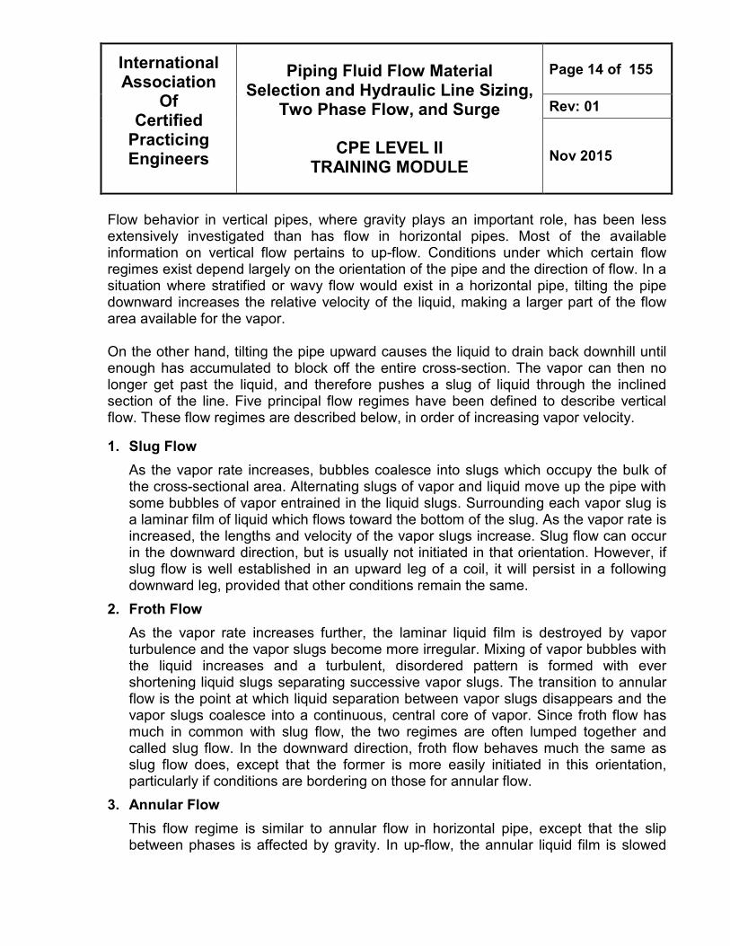
Flow behavior in vertical pipes, where gravity plays an important role, has been less extensively investigated than has flow in horizontal pipes. Most of the available information on vertical flow pertains to up-flow. Conditions under which certain flow regimes exist depend largely on the orientation of the pipe and the direction of flow. In a situation where stratified or wavy flow would exist in a horizontal pipe, tilting the pipe downward increases the relative velocity of the liquid, making a larger part of the flow area available for the vapor. On the other hand, tilting the pipe upward causes the liquid to drain back downhill until enough has accumulated to block off the entire cross-section. The vapor can then no longer get past the liquid, and therefore pushes a slug of liquid through the inclined section of the line. Five principal flow regimes have been defined to describe vertical flow. These flow regimes are described below, in order of increasing vapor velocity.
1. Slug Flow
As the vapor rate increases, bubbles coalesce into slugs which occupy the bulk of the cross-sectional area. Alternating slugs of vapor and liquid move up the pipe with some bubbles of vapor entrained in the liquid slugs. Surrounding each vapor slug is a laminar film of liquid which flows toward the bottom of the slug. As the vapor rate is increased, the lengths and velocity of the vapor slugs increase. Slug flow can occur in the downward direction, but is usually not initiated in that orientation. However, if slug flow is well established in an upward leg of a coil, it will persist in a following downward leg, provided that other conditions remain the same.
2. Froth Flow
As the vapor rate increases further, the laminar liquid film is destroyed by vapor turbulence and the vapor slugs become more irregular. Mixing of vapor bubbles with the liquid increases and a turbulent, disordered pattern is formed with ever shortening liquid slugs separating successive vapor slugs. The transition to annular flow is the point at which liquid separation between vapor slugs disappears and the vapor slugs coalesce into a continuous, central core of vapor. Since froth flow has much in common with slug flow, the two regimes are often lumped together and called slug flow. In the downward direction, froth flow behaves much the same as slug flow does, except that the former is more easily initiated in this orientation, particularly if conditions are bordering on those for annular flow.
3. Annular Flow
This flow regime is similar to annular flow in horizontal pipe, except that the slip between phases is affected by gravity. In up-flow, the annular liquid film is slowed
International Association
Of Certified
Practicing Engineers
Piping Fluid Flow Material Selection and Hydraulic Line Sizing,
Two Phase Flow, and Surge
CPE LEVEL II TRAINING MODULE
Page 15 of 155
Rev: 01
Nov 2015
down by gravity, which increases the difference in velocities between vapor and liquid. In down-flow, the reverse is true, with gravity speeding up the liquid and reducing the difference in velocities between vapor and liquid. On the other hand, the liquid film thickness is more uniform around the circumference of the pipe than in horizontal flow. Annular flow tends to be the dominant regime In vertical down-flow.
4. Mist Flow
This flow regime is essentially the same as spray flow in horizontal pipe. The very high vapor rates required to completely disperse the liquid essentially eliminate the effects of orientation and direction of flow. In identification of vertical two-phase flow regimes, annular and mist flow are often considered together (and called annular-mist).
(a) (b) (c)
International Association
Of Certified
Practicing Engineers
Piping Fluid Flow Material Selection and Hydraulic Line Sizing,
Two Phase Flow, and Surge
CPE LEVEL II TRAINING MODULE
Page 16 of 155
Rev: 01
Nov 2015
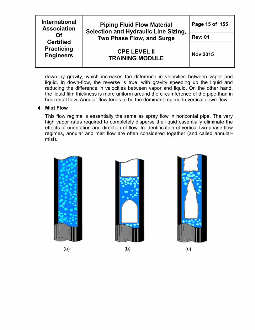
(d) (e) Figure 2: Flow regime in vertical pipeline; (a). Bubble flow, (b) Slug flow, (c) Froth flow,
(d) Annular flow, (e) Mist flow, The behavior of a two-phase mixture in a tee is highly unpredictable. Liquid or vapor may prefer one branch over the other resulting in uneven splitting, so that the volume fraction of vapor (or liquid) differs in the two split streams. It is generally true that if the flow entering the tee is a dispersed flow the split will be more even than when the entering stream is in a separated flow regime. The splitting of a two-phase stream in a pipe tee is also dependent on the configuration of the flow. In general the splitting is more even if it is done in a more symmetrical fashion.
International Association
Of Certified
Practicing Engineers
Piping Fluid Flow Material Selection and Hydraulic Line Sizing,
Two Phase Flow, and Surge
CPE LEVEL II TRAINING MODULE
Page 17 of 155
Rev: 01
Nov 2015
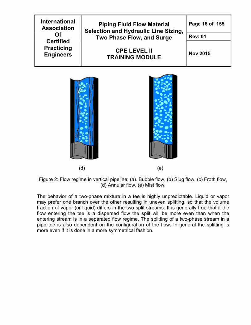
Splitting is more even in an impacting tee (a) than in a straight-through tee (b) as shown below. In order to maintain symmetry, elbows immediately upstream of an impacting tee should be mounted perpendicular to the plane of the tee. If this is not possible a blanked-off tee should be used instead of the elbow.
(a) (b)
Figure 3: (a) an impacting tee and (b) a straight-through tee
Characteristic of two phase fluid flow
1. Surface tension makes all dynamical problems nonlinear.
2. In the case of air and water at standard temperature and pressure, the density of the two phases differs by a factor of about 1000. Similar differences are typical of water liquid/water vapor densities.
3. The sound speed changes dramatically for materials undergoing phase change, and can be orders of magnitude different. This introduces compressible effects into the problem.
4. The phase changes are not instantaneous, and the liquid vapor system will not necessarily be in phase equilibrium.
International Association
Of Certified
Practicing Engineers
Piping Fluid Flow Material Selection and Hydraulic Line Sizing,
Two Phase Flow, and Surge
CPE LEVEL II TRAINING MODULE
Page 18 of 155
Rev: 01
Nov 2015
Liquid Surge “Hydraulic transient”, “surge pressure” or, in water applications, “water hammer” is a type of hydraulic transient that refers to rapid changes of pressure in a pipe system that can have devastating consequences, such as collapsing pipes and ruptured valves. It is therefore important to understand the phenomena that contribute to transient formation and be able to accurately calculate and analyze changes as well as maximum and minimum pressures occurring in a pipe system. The term “surge” refers to those unsteady flow situations that can be analyzed by considering the fluid to be incompressible and the conduit walls rigid. Transient pressures are most important when the rate of flow is changed rapidly, such as resulting from rapid valve closures or pump stoppages. Such disturbances, whether caused by design or accident, may create traveling pressure and velocity waves of large magnitude. These transient pressures are superimposed on the steady-state conditions present in the line at the time the transient pressure occurs. The severity of transient pressures must be determined so that the water mains can be properly designed to withstand these additional loads. Water hammer causes piping, valves, pipe fixtures, supports, system components, etc. to suffer the added strain of dynamic loads. The term “water hammer” is used to describe the phenomenon occurring in a closed conduit when there is either an acceleration or retardation of the flow. In contrast to a force, pressure is non-directional; i.e. it does not have a vector. Not until a hydrostatic pressure starts acting on a limiting area, is a force exerted in the direction of the area normal. Water hammer occurs when the flow of moving water is suddenly stopped by a closing valve. Because of the compressibility of water and the elasticity of pipes, pressure waves will then propagate in the pipe until they are attenuated at a velocity, which is dependent upon pipe material and wall thickness. This sudden stop causes the whole column of water behind the valve to slam into the valve, and itself. Rapid pressure changes are a result of rapid changes in flow, which generally occur in a pipe system after pump shut-off, although it may also occur at pump start or at valve opening or closing. The tremendous spike of pressure that is caused, is called water hammer, and it not only acts like a tiny explosion inside pipes, it can be just as destructive. Under unfavorable circumstances, damage due to water hammer may occur in pipelines measuring more than one hundred meters and conveying only several tenths of a liter
International Association
Of Certified
Practicing Engineers
Piping Fluid Flow Material Selection and Hydraulic Line Sizing,
Two Phase Flow, and Surge
CPE LEVEL II TRAINING MODULE
Page 19 of 155
Rev: 01
Nov 2015
per second. But even very short, unsupported pipelines in pumping stations can be damaged by resonant vibrations if they are not properly anchored.
Figure 4: Water Hammer Description A pumping system can never be operated in steady-state (the term steady means that volume rates of flow, pressures and pump speeds do not change with time) condition all the time, since starting up and stopping the pump alone will change the duty conditions. Generally speaking, every change in operating conditions and every disturbance cause pressure and flow variations or, put differently, cause the flow conditions to change with time.
1. Valve closed – water still
2. Valve open – moving water
3. Valve closes – water hammer
International Association
Of Certified
Practicing Engineers
Piping Fluid Flow Material Selection and Hydraulic Line Sizing,
Two Phase Flow, and Surge
CPE LEVEL II TRAINING MODULE
Page 20 of 155
Rev: 01
Nov 2015
Flow conditions of this kind are commonly referred to as unsteady or transient. Referring specifically to pressures, they are sometimes called dynamic pressure changes or pressure transients. The main causes of transient flow conditions are:
• Pump trip as a result of switching off the power supply or a power failure.
• Starting or stopping up one or more pumps whilst other pumps are in operation.
• Closing or opening of shut-off valves in the piping system.
• Excitation of resonant vibrations by pumps with an unstable H/Q curve.
• Variations of the inlet water level.
Typical events that require transient considerations include the following:
• Pump startup or shutdown;
• Changes in valve settings, accidental or planned Valve opening or closing (variation in cross-sectional flow area);
• Changes in boundary pressures (e.g., losing overhead storage tank, adjustments in the water level at reservoirs, pressure changes in tanks, and so on);
• Rapid changes in demand conditions (e.g., hydrant flushing);
• Changes in transmission conditions (e.g., main break or line freezing)
• Pipe filling or draining.
• Changes in power demand in turbines
• Action of reciprocating pumps
• Changing elevation of a reservoir
• Waves o a reservoir
• Turbine governor hunting
• Vibration of impellers or guide vanes in pumps, fans, or turbines
• Vibration of deformable appurtenances such as valves
• Draft tube instabilities due to vortexing
• Unstable pump or fan characteristics
International Association
Of Certified
Practicing Engineers
Piping Fluid Flow Material Selection and Hydraulic Line Sizing,
Two Phase Flow, and Surge
CPE LEVEL II TRAINING MODULE
Page 21 of 155
Rev: 01
Nov 2015
Figure 5: Steady-state pressure head curve of a pumping system Hydraulic transient events are disturbances in the water caused during a change in state, typically effecting a transition from one steady or equilibrium condition to another. The principle components of the disturbances are pressure and flow changes at a point that cause propagation of pressure waves throughout the distribution system. The pressure waves travel with the velocity of sound (i.e., acoustic or sonic speed), which depends on the elasticity of the water and the elastic properties (e.g., material and wall thickness) of the pipe. As these waves propagate, they create a transient adjustment to the pressure and flow conditions throughout the system. Over time, damping actions and friction reduce the waves until the system stabilizes at a new steady state.
International Association
Of Certified
Practicing Engineers
Piping Fluid Flow Material Selection and Hydraulic Line Sizing,
Two Phase Flow, and Surge
CPE LEVEL II TRAINING MODULE
Page 22 of 155
Rev: 01
Nov 2015
It is difficult to determine when the risk of water hammer exists and calculations are required, there are several factors that generally indicate when taking precautions against water hammer is advisable. Pipeline profile. The minimum pressure line (green profile in graph below) depends upon various factors such as the wave speed and the pump’s moment of inertia. Therefore the minimum pressure line will retain the same shape regardless of the pipeline profile (dark blue profiles) as long as no vaporization occurs. The magnitude of the sub pressure that the pipe will experience will therefore depend on the pipeline profile Pipeline length. Pipe length will influence the reflection time and the inertia of water inside the pipe. The longer the pipe is, the longer the reflection time, that is, the time it takes for the wave to reflect at the outlet and return to the starting point. In addition, the longer the pipe, the larger the mass of water that will affect the moment of inertia of the water column Moment of inertia A pump’s moment of inertia plays a critical role in water hammer events. The higher the moment of inertia, the longer the pump will continue to rotate after shut-off. A higher moment of inertia minimizes pressure drops before the reflecting wave raises the pressure again. Pipe material and dimensions Joukowsky’s equation states that the magnitude of water hammer is directly proportional to the velocity of the wave propagation. Wave propagation velocity depends on the elasticity of the pipe walls and the compressibility of the liquid. A typical value for wave propagation velocity in PVC pipes containing water is 300 m/s (985 ft/s) and for steel pipes 1,100 m/s (3600 ft/s). The pipe dimensions will also affect the wave speed. Filling around the pipeline The type of filling and packing method used around the pipeline has a direct impact on the external pressure on the pipelines. Due to the pressure changes created by water
International Association
Of Certified
Practicing Engineers
Piping Fluid Flow Material Selection and Hydraulic Line Sizing,
Two Phase Flow, and Surge
CPE LEVEL II TRAINING MODULE
Page 23 of 155
Rev: 01
Nov 2015
hammer, there will be oscillations of the pipe in the ground, therefore the filling around the pipe will have a great effect on the wear of the pipe. Sharp stones, for example, will tear the pipe exterior. For submerged pipes, consideration must also be given to the depth of the pipe because the pipe wall is subject to the difference in pressure between the pressure inside the pipe and the external pressure from the surrounding water. If the pressure from the surrounding water is greater than the pressure inside the pipe, there is a risk of collapse or buckling. The effects of the water hammer vary, ranging from slight changes in pressure and velocity to sufficiently high pressure or vacuum through to failure of fittings, burst pipes and pump damage. Pump stop can create hard-to-handle water hammer conditions; the most severe conditions result from a sudden power failure that causes all pumps to stop simultaneously.
Some representative incidents caused by water hammer are listed in the following: Pressure rise:
• Pipe rupture
• Damaged pipe fixtures
• Damage to pumps, foundations, pipe internals and valves
Pressure fall:
• Buckling of plastic and thin walled steel pipes
• Disintegration of the cement lining of pipes
• Dirty water or air being drawn into pipelines through flanged or socket connections, gland packing or leaks
• Water column separation followed by high increases in pressure when the separate liquid columns recombine (macro-cavitation)
Pipe length (m)
International Association
Of Certified
Practicing Engineers
Piping Fluid Flow Material Selection and Hydraulic Line Sizing,
Two Phase Flow, and Surge
CPE LEVEL II TRAINING MODULE
Page 24 of 155
Rev: 01
Nov 2015
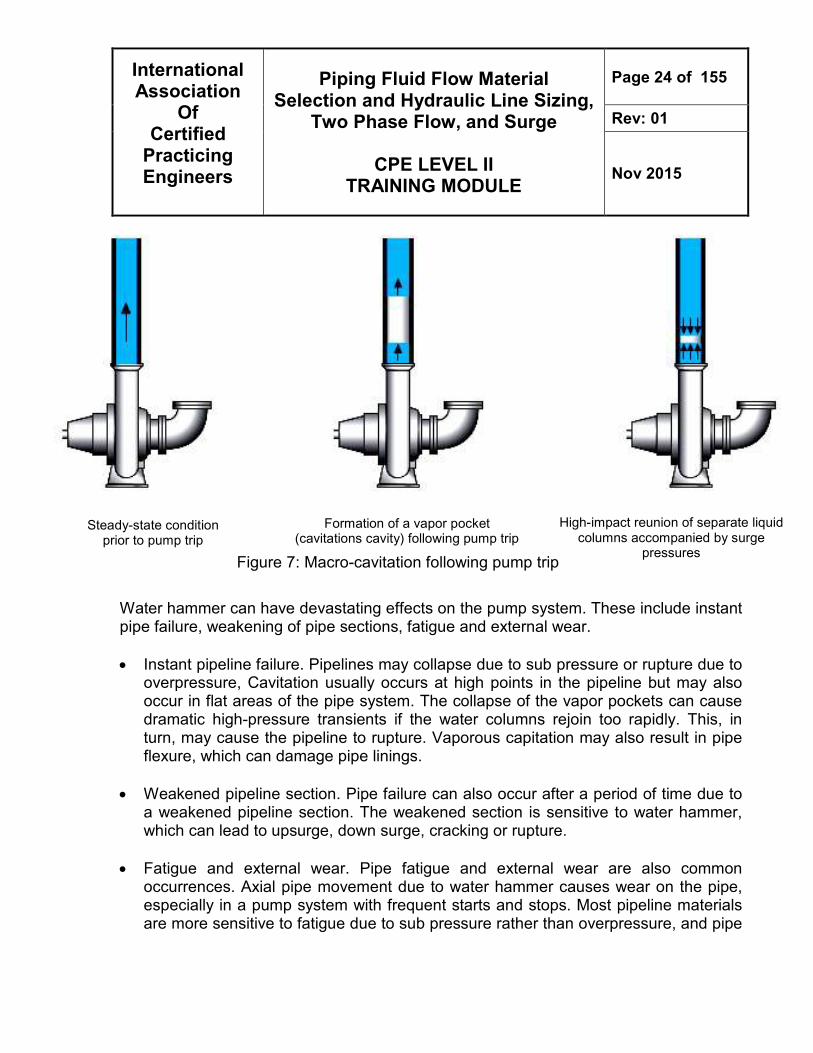
Figure 7: Macro-cavitation following pump trip
Water hammer can have devastating effects on the pump system. These include instant pipe failure, weakening of pipe sections, fatigue and external wear.
• Instant pipeline failure. Pipelines may collapse due to sub pressure or rupture due to overpressure, Cavitation usually occurs at high points in the pipeline but may also occur in flat areas of the pipe system. The collapse of the vapor pockets can cause dramatic high-pressure transients if the water columns rejoin too rapidly. This, in turn, may cause the pipeline to rupture. Vaporous capitation may also result in pipe flexure, which can damage pipe linings.
• Weakened pipeline section. Pipe failure can also occur after a period of time due to a weakened pipeline section. The weakened section is sensitive to water hammer, which can lead to upsurge, down surge, cracking or rupture.
• Fatigue and external wear. Pipe fatigue and external wear are also common occurrences. Axial pipe movement due to water hammer causes wear on the pipe, especially in a pump system with frequent starts and stops. Most pipeline materials are more sensitive to fatigue due to sub pressure rather than overpressure, and pipe
Steady-state condition prior to pump trip
Formation of a vapor pocket (cavitations cavity) following pump trip
High-impact reunion of separate liquid columns accompanied by surge
pressures
International Association
Of Certified
Practicing Engineers
Piping Fluid Flow Material Selection and Hydraulic Line Sizing,
Two Phase Flow, and Surge
CPE LEVEL II TRAINING MODULE
Page 25 of 155
Rev: 01
Nov 2015
fatigue is more pronounced when using plastic pipes. Dimensioning of sub pressure depends largely on the pipe material and wall thickness
• Slamming valves. Slamming valves are typically the cause of very high water column occurring at pump stop. When the pump is stopped, the water decelerates and reverses direction. Typically slamming valves can be seen in a system with a short pipe length and a relatively high static head while water hammer typically appears in systems with long pipe length and small static head. A high head and a short pipe length will cause a high water column deceleration.
• Maximum pressure in the system; Maximum pressures during transient regimes may destroy pipelines, tunnels, valves, or other components, causing considerable damage and sometimes loss of human life. Less drastically, strong pressure surges may cause cracks in an internal lining, damage connections and flanges between pipe sections, or destroy or cause deformations to equipment (such as pipeline valves, air valves, or any water hammer protection device).
• Vacuum conditions can create high stresses and strains that are much greater than those occurring during typical operating regimes. Vacuum pressures may cause the collapse of thin-walled pipes or reinforced concrete sections, particularly if these sections are not designed to withstand such strains.
• Occurrence of local vacuum conditions at specific locations and/or cavitation, either within specific devices or within a pipe. Cavitations occur when the local pressure is lowered to the value of vapor pressure at the ambient temperature. At this pressure, gas within the water is gradually released and the water starts to vaporize. When the pressure recovers, water enters the cavity caused by the gases and collides with whatever confines the cavity (i.e., another mass of water or a fixed boundary), resulting in a pressure surge.
• Hydraulic vibration of a pipe, its supports, or in specific devices and/or strong oscillations or rapid movement of the water masses. Oscillations of the water masses between the reservoirs, basins, and water towers may cause noise, concussions, suction of air into the line, and other serious problems, including temporarily losing control of the system. Strong hydraulic vibrations can damage pipelines, tunnels, tunnel internal linings, or measuring and control equipment, and even crumble concrete. Long-term moderate surges may gradually induce fatigue failures.
• Risk or occurrence of contamination at cross-connections. These events can generate high intensities of fluid shear and may cause resuspension of settled a pipe
International Association
Of Certified
Practicing Engineers
Piping Fluid Flow Material Selection and Hydraulic Line Sizing,
Two Phase Flow, and Surge
CPE LEVEL II TRAINING MODULE
Page 26 of 155
Rev: 01
Nov 2015
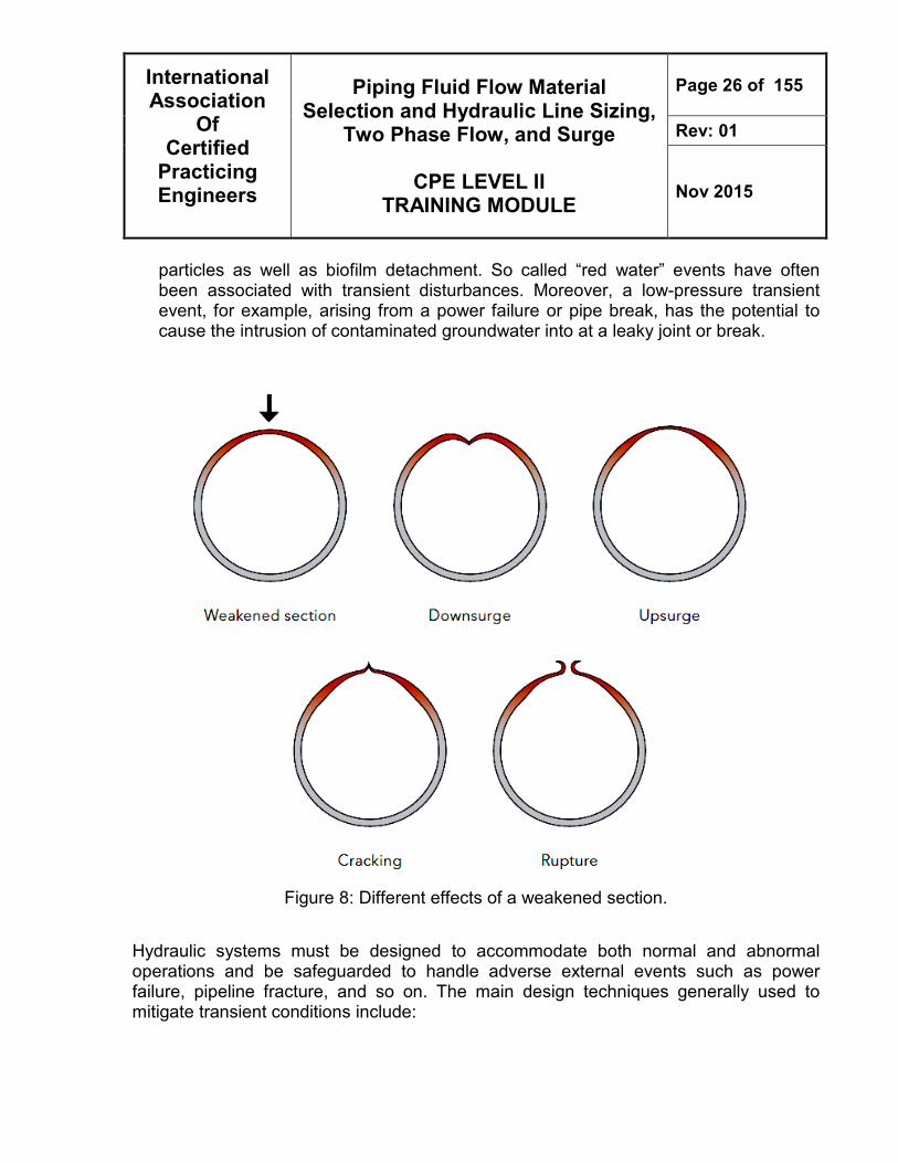
particles as well as biofilm detachment. So called “red water” events have often been associated with transient disturbances. Moreover, a low-pressure transient event, for example, arising from a power failure or pipe break, has the potential to cause the intrusion of contaminated groundwater into at a leaky joint or break.
Figure 8: Different effects of a weakened section.
Hydraulic systems must be designed to accommodate both normal and abnormal operations and be safeguarded to handle adverse external events such as power failure, pipeline fracture, and so on. The main design techniques generally used to mitigate transient conditions include:
International Association
Of Certified
Practicing Engineers
Piping Fluid Flow Material Selection and Hydraulic Line Sizing,
Two Phase Flow, and Surge
CPE LEVEL II TRAINING MODULE
Page 27 of 155
Rev: 01
Nov 2015
• Alteration of pipeline characteristics (e.g., pipe diameter),
• Improvement in valve and pump control procedures
• Design and installation of surge protection devices
DEFINITIONS
A variable frequency drive (VFD) is an electric control that can change the frequency of the current to the pump and thereby change the impeller speed.
Air chamber is a reservoir, connected to the pipeline, which is filled with liquid and compressed air.
Bladder tank. This vessel has a bladder that is precharged to a predetermined pressure to maintain the desired air volume under normal operating conditions.
Bypass - any system of pipes or conduits for redirecting the flow of a liquid. Also can be defined as A pipe or channel used to conduct gas or liquid around another pipe or a fixture.
Cavitation - the formation of vapor cavities in a liquid – i.e. small liquid-free zones ("bubbles" or "voids") – that are the consequence of forces acting upon the liquid. It usually occurs when a liquid is subjected to rapid changes of pressure that cause the formation of cavities where the pressure is relatively low.
Coalesce - to grow together or into one body: The two lakes coalesced into one.
Compressible Fluid - Molecules in a fluid to be compacted and the density is varies. Energy is exchanged not only among the kinetic energy and the potential energies due to gravity and pressure, but also with the internal energy (7).
Cracking - thermal decomposition, sometimes with catalysis, of a complex substance, especially the breaking of petroleum molecules into shorter molecules to extract low-boiling fractions such as gasoline.
International Association
Of Certified
Practicing Engineers
Piping Fluid Flow Material Selection and Hydraulic Line Sizing,
Two Phase Flow, and Surge
CPE LEVEL II TRAINING MODULE
Page 28 of 155
Rev: 01
Nov 2015
Critical flow - If the pressure drop is severe enough, a situation can arise in which the release rate becomes independent of the surrounding pressure. In other words, the release rate cannot be increased by further reduction in the surrounding pressure
Critical point - The location along the flow path that experiences the steepest pressure gradient in critical flow. For a valve or a nozzle, the critical point is located at the narrowest point of the device and for a crack or a short pipe, it is usually at the exit.
Critical pressure ratio - the ratio of the pressure at the critical point to the stagnation pressure.
Darcy Friction Factor, f -This factor is a function of Reynolds Number and relative pipe wall roughness, ε/d. For a given class of pipe material, the roughness is relatively independent of the pipe diameter, so that in a plot of f vs. Re, d often replaces ε/d as a parameter.
Downstream - The downstream stage in the production process involves processing the materials collected during the upstream stage into a finished product.
Fanning Friction Factor - Empirical factor in the Fanning equation for pressure drop in straight pipe. This factor is a function of Reynolds Number and relative pipe wall roughness, ε/d. For a given class of pipe material, the roughness is relatively independent of the pipe diameter, so that in a plot of f vs. Re, d often replaces ε/d as a parameter. The Fanning friction factor should not be confused with the Darcy friction factor, which is four times as large.
Fatigue damage is caused when the pipe is subjected to large alternating stresses, for example when the drill pipe rotates in a curved segment (dog-leg) of the well bore, which may be the result of unintentional deviations or which are necessary for directional and horizontal wells
Fitting - An accessory such as a locknut, bushing, or other part of a wiring system that is intended primarily to perform a mechanical rather than an electrical function.
Flashing - When a liquid or a vapor-liquid mixture under pressure is released to the surroundings through a pressure relief valve or a crack in a pipe or vessel
International Association
Of Certified
Practicing Engineers
Piping Fluid Flow Material Selection and Hydraulic Line Sizing,
Two Phase Flow, and Surge
CPE LEVEL II TRAINING MODULE
Page 29 of 155
Rev: 01
Nov 2015
Flow maldistribution - In branching flows, such as tee junctions or perforated pipe distributors, the flow maldistribution measures the preferential distribution of flow among alternative paths.
Flow regime - A range of stream flows having similar bed forms, flow resistance, and means of transporting sediment. When two phases flow co-currently in a channel, they can arrange themselves in a number of different configurations.
Hydraulic pressure - (transient flow) occurs when the flow of fluid in a pipeline is abruptly changed. Piping systems that use quick acting valves, or use pumps that start up or shut down rapidly, are susceptible to pressure transients (surges). These conditions can result in piping failure, damage to pumps, fittings, instrumentation, and other system components.
Impellers - a rotor used to increase (or decrease in case of turbines) the pressure and flow of a fluid. A rotating component of a centrifugal pump, usually made of iron, steel, bronze, brass, aluminum or plastic, which transfers energy from the motor that drives the pump to the fluid being pumped by accelerating the fluid outwards from the center of rotation.
In-Compressible Fluid - An incompressible flow is one in which the density of the fluid is constant or nearly constant. Liquid flows are normally treated as incompressible (6). Molecules in a fluid to be cannot be compacted. Generally the flow energy is converted to friction, kinetic and potential energy if available and not the internal energy.
Laminar or Viscous Flow - Laminar flow occurs when adjacent layers of fluid move relative to each other in smooth streamlines, without macroscopic mixing. In laminar flow, viscous shear, which is caused by molecular momentum exchange between fluid layers, is the predominant influence in establishing the fluid flow. This flow type occurs in pipes when Re < 2,100.
Liquid slugging - a condition which occurs when liquid is allowed to enter one or more cylinders. Where extreme cases of flooded start or liquid flood back occur.
Maldistribution - bad or faulty distribution, undesirable inequality or unevenness of placement or apportionment (as of population, resources, or wealth) over an area or among members of a group
International Association
Of Certified
Practicing Engineers
Piping Fluid Flow Material Selection and Hydraulic Line Sizing,
Two Phase Flow, and Surge
CPE LEVEL II TRAINING MODULE
Page 30 of 155
Rev: 01
Nov 2015
Moment of inertia - the mass property of a rigid body that defines the torque needed for a desired angular acceleration about an axis of rotation. A larger moment of inertia around a given axis requires more torque to increase the rotation, or to stop the rotation, of a body about that axis.
Newtonian Fluids - A fluid characterized by a linear relationship between shear rate (rate of angular deformation) and shear stress.
Non-Newtonian Liquids - Fluids may be broadly classified by their ability to retain the memory of a past deformation (which is usually reflected in a time dependence of the material properties). Fluids that display memory effects usually exhibit elasticity.(8) Fluids in which viscosity depends on shear rate and/or time. Examples are some slurries, emulsions, and polymer melts and solutions.
Phase equilibrium – phase where The energy of a system does not change when a particle undergoes a transition from one phase to another at equilibrium. In other words, the chemical potentials of each component in the different phases are equal at equilibrium
Physical properties – any property use to characterize matter and energy and their interactions. The measurement of physical properties may change the arrangement of matter but not the structure of its molecules.
Pipeline - a line of pipe or A conduit of pipe with pumps, valves, and control devices for conveying liquids, gases, or finely divided solids.
Pressure drops - the difference in pressure between two points of a fluid carrying network. Pressure drop occurs when frictional forces, caused by the resistance to flow, act on a fluid as it flows through the tube.
Relative Roughness - Ratio of absolute pipe wall roughness ε to inside diameter d, in consistent units.
Relief system - an emergency system for discharging gas during abnormal conditions, by manual or controlled means or by an automatic pressure relief valve from a pressurized vessel or piping system, to the atmosphere to relieve pressures in excess of the maximum allowable working pressure (MAWP)
International Association
Of Certified
Practicing Engineers
Piping Fluid Flow Material Selection and Hydraulic Line Sizing,
Two Phase Flow, and Surge
CPE LEVEL II TRAINING MODULE
Page 31 of 155
Rev: 01
Nov 2015
Reservoir - large tank used for collecting and storing water, esp for community water supplies or irrigation
Resistance Coefficient, K - Empirical coefficient in the friction loss equation for valves and fittings. It expresses the number of velocity heads lost by friction for the particular valve or fitting. The coefficient is usually a function of the nominal diameter.
Reynolds Number, Re - A dimensionless number which expresses the ratio of inertial to viscous forces in fluid flow.
Shear Stress - Force per unit area. Force in direction of flow; area in plane normal to velocity gradient.
Slug catchers - devices at the downstream end or other intermediate points of a pipeline to absorb the fluctuating liquid inlet flow rates through liquid level fluctuation.
Sonic Velocity (Choked Flow) - The maximum velocity that a gas or gas-liquid mixture can attain in a conduit at a given upstream pressure (except in certain converging-diverging nozzles), no matter how low the discharge pressure is. For gases this maximum velocity is equal to the speed of sound at the local conditions.
Specific gravity - The ratio of the mass of a given volume of a substance to that of another equal volume of another substance used as standard. Unless otherwise stated, air is used as the standard for gases and water for liquids, with the volumes measured at 60°F and standard atmospheric pressure.
Stagnation - Location upstream of the critical point where flow is stagnant or moving very slowly.
Steady-state - volume rates of flow, pressures and pump speeds do not change with time) condition all the time, since starting up and stopping the pump alone will change the duty conditions.
Steam Hammer - Steam hammer is excessive pipe vibrations that occur due to the collapse of large vapor bubbles in a cool liquid stream.
Surface tension - A property of liquids arising from unbalanced molecular cohesive forces at or near the surface, as a result of which the surface tends to contract and has properties resembling those of a stretched elastic membrane.
International Association
Of Certified
Practicing Engineers
Piping Fluid Flow Material Selection and Hydraulic Line Sizing,
Two Phase Flow, and Surge
CPE LEVEL II TRAINING MODULE
Page 32 of 155
Rev: 01
Nov 2015
Surge control – methods or equipments which are used to prevent pressure surges, which can occur in a hydraulic system when the flow in a pipeline is stopped too quickly.
Surge tower/tank - a standpipe or storage reservoir at the downstream end of a closed aqueduct or feeder or a dam or barrage pipe to absorb sudden rises of pressure, as well as to quickly provide extra water during a brief drop in pressure.
Transient pressures - used to refer to any pressure wave that is short lived (i.e. not static pressure or pressure differential due to friction/minor loss in flow). The most common occurrence of this is called water hammer.
Transition Flow - Flow regime lying between laminar and turbulent flow. In this regime velocity fluctuations may or may not be present and flow may be intermittently laminar and turbulent. This flow type occurs in pipes when 2,100 < Re < 4,000.
Turbulent Flow - Turbulence is characterized by velocity fluctuations that transport momentum across streamlines; there is no simple relationship between shear stress and strain rate in turbulent flow. Instantaneous properties cannot be predicted in a turbulent flow field; only average values can be calculated. For engineering analyses, turbulent flow is handled empirically using curve-fits to velocity profiles and experimentally determinate loss coefficients. This flow type occurs in pipes in industrial situations when Re > 4,000. Under very controlled laboratory situations, laminar flow may persist at Re > 4,000.
Upstream - The upstream stage of the production process involves searching for and extracting raw materials.
Vacuum breaker - A pipe or fixture element in a water supply system that prevents siphon or suction action and the backflow that can result
Vacuum conditions – a condition in which there is no matter or in which the pressure is so low that any particles in the space do not affect any processes being carried on there. It is a condition well below normal atmospheric pressure
Velocity slip - In actual two-phase flow there is slip between vapor and liquid, with vapor flowing at a higher average velocity.
Viscosity- Defined as the shear stress per unit area at any point in a confined fluid divided by the velocity gradient in the direction perpendicular to the direction of flow, if
International Association
Of Certified
Practicing Engineers
Piping Fluid Flow Material Selection and Hydraulic Line Sizing,
Two Phase Flow, and Surge
CPE LEVEL II TRAINING MODULE
Page 33 of 155
Rev: 01
Nov 2015
the ratio is constant with time at a given temperature and pressure for any species, the fluid is called a Newtonian fluid.
Water hammer - a pressure surge or wave caused when a fluid (usually a liquid but sometimes also a gas) in motion is forced to stop or change direction suddenly (momentum change). Water hammer commonly occurs when a valve closes suddenly at an end of a pipeline system, and a pressure wave propagates in the pipe. It is also called hydraulic shock.
Wave propagation velocity - a true speed or velocity in units of distance per time or the speed at which a wave front
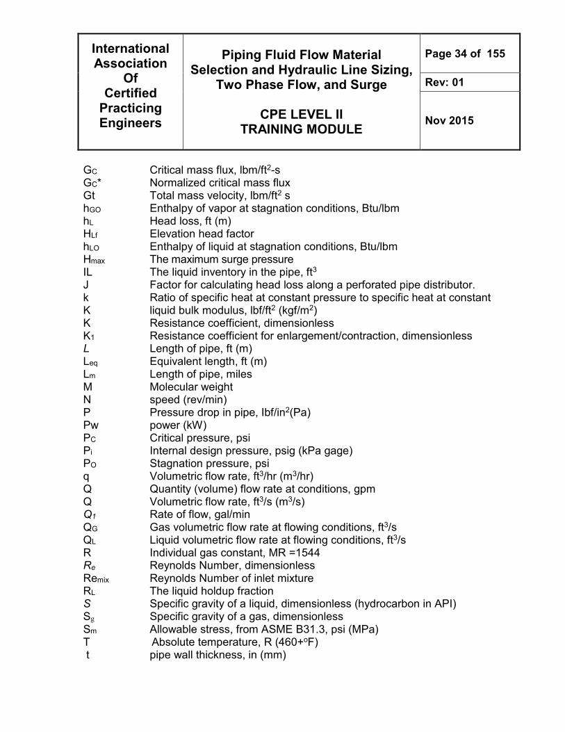
NOMENCLATURE A Radius-sectional area, ft2 (m2) a Sum of mechanical allowances plus corrosion allowance plus erosion
allowance, in(mm) Ap cross sectional area based on pipe inside diameter,ft2 (m2) Av cross sectional area based on valve nominal size, ft2 (m2) C Flow coefficient for the nozzles and orifices c Compressible factor, for perfect gas c =1.0 C pipe constraint coefficient (Usually, 1.0 is applicable) CLO Heat capacity of liquid at stagnation conditions, Btu/lbmF D pipe inside diameter, in (mm) d Inside diameter of pipe, in d1 Pipe with smaller diameter in enlargements or contractions in pipes d2 Pipe with smaller diameter in enlargements or contractions in pipes de Equivalent hydraulic diameter, in (mm) DIM diameter impeller in (mm) Do Outside diameter of pipe, in. (mm) E Weld joint efficiency or quality factor from ASME B31.3 E pipe material Young’s modulus, lbf/ft2 (kgf/m2) Ek The kinetic energy per unit volume of the inlet stream, psi f Dancy’s friction factor, dimensionless F Funning friction factor) fn The single phase friction factor, ft Friction factor for fitting ftpr The two-phase friction factor ratio, g Acceleration of gravity, ft/s2 (m/s2) – 32.2ft/s2
International Association
Of Certified
Practicing Engineers
Piping Fluid Flow Material Selection and Hydraulic Line Sizing,
Two Phase Flow, and Surge
CPE LEVEL II TRAINING MODULE
Page 34 of 155
Rev: 01
Nov 2015
GC Critical mass flux, lbm/ft2-s GC* Normalized critical mass flux Gt Total mass velocity, lbm/ft2 s hGO Enthalpy of vapor at stagnation conditions, Btu/lbm hL Head loss, ft (m) HLf Elevation head factor hLO Enthalpy of liquid at stagnation conditions, Btu/lbm Hmax The maximum surge pressure IL The liquid inventory in the pipe, ft3
J Factor for calculating head loss along a perforated pipe distributor. k Ratio of specific heat at constant pressure to specific heat at constant K liquid bulk modulus, lbf/ft2 (kgf/m2) K Resistance coefficient, dimensionless K1 Resistance coefficient for enlargement/contraction, dimensionless L Length of pipe, ft (m) Leq Equivalent length, ft (m) Lm Length of pipe, miles M Molecular weight N speed (rev/min) P Pressure drop in pipe, Ibf/in2(Pa) Pw power (kW) PC Critical pressure, psi Pi Internal design pressure, psig (kPa gage) PO Stagnation pressure, psi q Volumetric flow rate, ft3/hr (m3/hr) Q Quantity (volume) flow rate at conditions, gpm Q Volumetric flow rate, ft3/s (m3/s) Q1 Rate of flow, gal/min QG Gas volumetric flow rate at flowing conditions, ft3/s QL Liquid volumetric flow rate at flowing conditions, ft3/s R Individual gas constant, MR =1544 Re Reynolds Number, dimensionless Remix Reynolds Number of inlet mixture RL The liquid holdup fraction S Specific gravity of a liquid, dimensionless (hydrocarbon in API) Sg Specific gravity of a gas, dimensionless Sm Allowable stress, from ASME B31.3, psi (MPa) T Absolute temperature, R (460+oF) t pipe wall thickness, in (mm)
International Association
Of Certified
Practicing Engineers
Piping Fluid Flow Material Selection and Hydraulic Line Sizing,
Two Phase Flow, and Surge
CPE LEVEL II TRAINING MODULE
Page 35 of 155
Rev: 01
Nov 2015
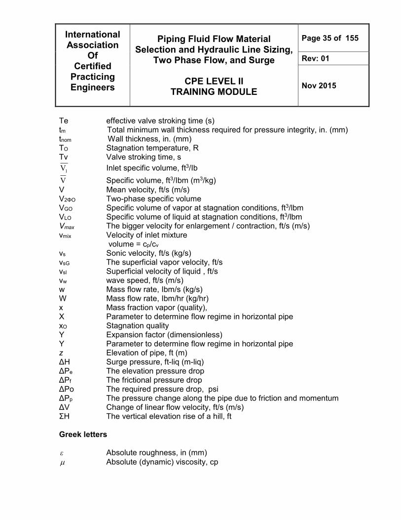
Te effective valve stroking time (s) tm Total minimum wall thickness required for pressure integrity, in. (mm) tnom Wall thickness, in. (mm) TO Stagnation temperature, R Tv Valve stroking time, s
1V Inlet specific volume, ft3/Ib
V Specific volume, ft3/Ibm (m3/kg) V Mean velocity, ft/s (m/s) V2ΦO Two-phase specific volume VGO Specific volume of vapor at stagnation conditions, ft3/lbm VLO Specific volume of liquid at stagnation conditions, ft3/lbm Vmax The bigger velocity for enlargement / contraction, ft/s (m/s) vmix Velocity of inlet mixture volume = cp/cv vs Sonic velocity, ft/s (kg/s) vsG The superficial vapor velocity, ft/s vsl Superficial velocity of liquid , ft/s vw wave speed, ft/s (m/s) w Mass flow rate, Ibm/s (kg/s) W Mass flow rate, Ibm/hr (kg/hr) x Mass fraction vapor (quality), X Parameter to determine flow regime in horizontal pipe xO Stagnation quality Y Expansion factor (dimensionless) Y Parameter to determine flow regime in horizontal pipe z Elevation of pipe, ft (m) ΔH Surge pressure, ft-liq (m-liq) ΔPe The elevation pressure drop ΔPf The frictional pressure drop ΔPo The required pressure drop, psi ΔPp The pressure change along the pipe due to friction and momentum ΔV Change of linear flow velocity, ft/s (m/s) ΣH The vertical elevation rise of a hill, ft Greek letters ε Absolute roughness, in (mm) µ Absolute (dynamic) viscosity, cp
International Association
Of Certified
Practicing Engineers
Piping Fluid Flow Material Selection and Hydraulic Line Sizing,
Two Phase Flow, and Surge
CPE LEVEL II TRAINING MODULE
Page 36 of 155
Rev: 01
Nov 2015
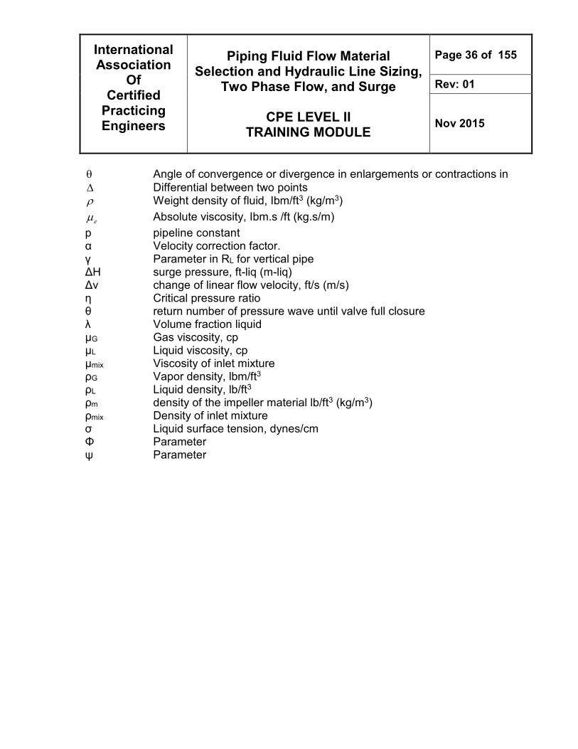
θ Angle of convergence or divergence in enlargements or contractions in ∆ Differential between two points ρ Weight density of fluid, Ibm/ft3 (kg/m3)
eµ Absolute viscosity, Ibm.s /ft (kg.s/m)
p pipeline constant
α Velocity correction factor. γ Parameter in RL for vertical pipe ΔH surge pressure, ft-liq (m-liq) Δv change of linear flow velocity, ft/s (m/s) η Critical pressure ratio θ return number of pressure wave until valve full closure λ Volume fraction liquid μG Gas viscosity, cp μL Liquid viscosity, cp μmix Viscosity of inlet mixture ρG Vapor density, lbm/ft3 ρL Liquid density, lb/ft3 ρm density of the impeller material lb/ft3 (kg/m3) ρmix Density of inlet mixture σ Liquid surface tension, dynes/cm Φ Parameter ψ Parameter


![Informational Holdup and Performance Persistence …faculty.haas.berkeley.edu/vissing/rfs_hlvj.pdf[12:00 29/7/2013 RFS-hht046.tex] Page: 1 1–51 Informational Holdup and Performance](https://img.pdfslide.net/doc/110x75/5e97e46e3fd609406356b3b9/informational-holdup-and-performance-persistence-1200-2972013-rfs-hht046tex.jpg)