Embed Size (px)
Citation preview
SERVICE BULLETIN
TO ALL OF THE OWNERS OF HAMILTON STANDARD’S SERVICE BULLETIN NO. 14RF-9-61-76 WITH THE DATE OF APR 1/95:
This letter of transmittal sends you Revision 1 of Service Bulletin No. 14RF-9-61-76 with the date of May 17/95.
This Service Bulletin revision increases the interval for the torque check of the primary ballscrew quill from 4000 to 5000 hours maximum of operational time. The date that all PCUs must include the secondary drive quill backup device is extended from June 30, 1997 to June 30,1998.
Please replace all of the pages of Service Bulletin No. 14RF-9-61-76 with Service Bulletin No. 14RF-9-61-76, Revision 1.
All of the pages of this revision have the new Revision 1 date. Revision bars are shown only where there are technical changes. Revision bars are not shown where an editorial change, such as a correction of a typographical error, a change in a step number, or a new location of text was necessary.
Hamilton Standard A United Technologies Company
TO ALL HOLDERS OF HAMILTON STANDARD SERVICE BULLETIN 14RF-9-61-76 WITH THE DATE OF APR 1/95. This letter of transmittal sends you Revision 2 of Service Bulletin No. 14RF-9-61-76 with the date of April 15/97. Page 2 we add FAA endorsement of Revision 2. On page 3, we add information for final production acceptance tests. On page 4, we update the address and Fax number.
On page 18, we change the process of application of Loctite 290. On page 24, we change the full travel distance of the tool from 20 O to 24 '. Also on page 24 and 25, we add specific instructions on how to align the primary ballscrew quill with the secondary drive quill. On page 25, we add Instructions on how to mark an index line on the OD of the servo ballscrew and on the OD of the ballscrew primary quill. On page 27, we add Figure 10. On page 28, we add the modification number.
On page 29, we add Instructions on how to mark (yellow paint) the external surface of the main housing to show that this Service Bulletin procedure has been done. Retain Service Bulletin No. 14RF-9-61-76, Revision 1, as the method of compliance with Airworthiness Directive 95-22-1 2. This bulletin, 14RF-9-61-76, Revision 2, has been FAA approved as an alternate method of com pl iance . All of the pages of this revision have the new Revision 2 date. Revision bars are shown only where there are technical changes. Revision bars are not shown where an editorial change, such as a correction of a typographical error, a change in a step number, or a new location of text was necessary.
Hamilton Standard A United Technologies Company
I
SERVICE BULLETIN
Revision Date Pages Affected
1 May 17/95 All
2 April 15/97 All
0 1995 by United Technologies Corporation Revised 1997
Model
14RF-9
PROPELLERS - CONTROL AND ADAPTER - INSTALLATION OF THE SECONDARY DRIVE QUILL
Propeller Control Propeller Control and Adapter PN Unit (PCU)PN
784770-4 7824 90-24
NOTE: To make the modifications of this Service Bulletin to propeller control and adapter PN 784770-3 and propeller control PN 782490-12, you must also do Service Bulletin 14RF-9-61-61 with this Service Bulletin unless it was previously done in the field ("SB14RF-9-61-61" is shown on the identification plate).
Service Bulletin 14RF-9-61-61 adds a new ballscrew quill damper, new shims, and replaces the (primary) ballscrew quill. The damper modification changes the propeller control and adapter to PN 784770-4 and the propeller control to PN 782490-24. The instructions in this Service Bulletin (14RF-9-61-76) refer, at the applicable times in the Accomplishment Instructions, to the procedures that need to be done in Service Bulletin 14RF-9-61-61.
The model 14RF-9 propeller control and adapter is used on EMB120 aircraft. B. Reason
(1) Problem. If the splines of the servo ballscrew or the ballscrew quill become badly worn, it is possible that the PCU cannot change the angle of the propeller blade.
(2) Cause. There are several different conditions that can possibly occur together and cause wear of the splines.
Apr 1 195 Revision 2 Apr 15/97
14RF-9-61-76 Page 1 of 34
Hamilton Standard A United Technologies Company
SERVICE BULLETIN (3) Solution. To improve the wear characteristics of the servo ballscrew splines, a
damper was added to the ballscrew quill in Service Bulletin 14 RF-9-61-61. This Service Bulletin (14RF-9-61-76) adds a secondary drive quill and related parts to the servo ballscrew to give back-up protection for the ballscrew quill (referred to subsequently as the primary ballscrew quill). Should the primary ballscrew quill become not able to transmit rotational signals from the servo ballscrew to the propeller transfer tube, the servo ballscrew will engage the secondary drive quill and keep full rotational control of the transfer tube by the PCU. The operation of the PCU is not changed when the secondary drive quill is engaged.
C. Description (1) A modification is made to the servo ballscrew and a new spring, spring spacer,
spring support, secondary drive quill, and drive pins are installed in it. After the PCU is assembled, it is installed in an indexing fixture. In this fixture, a tool is used to correctly align the secondary drive quill with the drive pins and to align the internal splines on the primary ballscrew quill with the secondary drive quill splines and with the splines in the ballscrew.
(2) A new torque check of the primary ballscrew quill is necessary at repair facilities. A procedure for this check, which is now included in the acceptance test procedures for the PCU, is given in this Service Bulletin.
installation of the secondary drive quill in a PCU. Repair facilities must complete this form for each PCU that is changed and send the form to us as specified in this Service Bulletin.
(3) Also, a form is given at the end of this Service Bulletin to make a record of
D. Compliance (1) Hamilton Standard anticipates that the FAA wili make it mandatory that all PCUs
include the new secondary drive quill by June 30, 1998. Hamilton Standard will install the secondary drive quill and related parts in a PCU when the unit is removed from an aircraft for cause or major inspection.
check of the primary ballscrew quill done every 5000 hours maximum of operational time. This check will make sure that the splines of the primary ballscrew quill are in satisfactory condition for continued operation of the PCU. The procedure to do this check is given in SB 14RF-9-61-75 .
(2) All PCUs that include the new secondary drive quill device must have the torque
E. Approval
The technical contents of Revision 1 of this Service Bulletin were accepted by the FAA on May 17, 1995.
Revision 2 of this Service Bulletin is approved by the FAA, by a letter endorsement dated March 26 1997, as an alternate method of compliance with Airworthiness Directive No. 95-22-1 2.
Apr 1 /95 Revision 2 Apr 15/97
14RF-9-61-76 Page 2
Hamilton Standard A United Technologies Company
SERVICE BULLETIN F. Manpower
Approximately 1.5 manhours are needed to make a modification of servo ballscrew PN 7901 02-1 to PN 790102-4. An additional 1.5 manhours of assembly time are needed for installation and alignment of the secondary drive quill. A final Production Acceptance Test must also be done for an additional 3 hours unless disassembly is required for other reas on s
G. Material - Cost and Availability I
The parts that are necessary to do these procedures are in a list in Section 3, Material Information. Hamilton Standard will give you the parts to do this Service Bulletin at no charge, one time only, on all PCUs PN 782490-12 or -24 that are removed from aircraft for scheduled maintenance or repair and returned before June 30, 1998 to:
Hamilton Standard Customer Support Center 471 Lakeshore Parkway Rock Hill, SC 29730
Or
Hamilton Standard Customer Support Center 4401 Donald Douglas Drive Long Beach, CA 90808
Or
Pratt & Whitney Overhaul Repair Center - Europe Maastricht Airport P.O. Box 269 6190 AG Beek (L) The Netherlands
Or
Hamilton Standard Customer Support Center 97 Newberry Road East Windsor, CT 06088
Or
Companhia Electromecanica (CELMA) Rue Alice Hewe 356 Bingen 25669 Petropolis - RJ - Brazil
Apr 1 /95 Revision 2 Apr 15/97
14RF-9-61-76 Page 3
Hamilton Standard A United Technologies Company
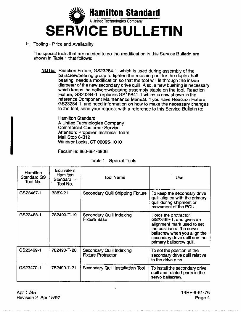
Secondary Quill Indexing Fixture Base
Secondary Quill Indexing Fixture Protractor
SERVICE BULLETIN
~ ~~ ~
Holds the protractor, GS23469-1, and gives an alignment mark used to set the position of the servo ballscrew when you align the secondary drive quill and the primary ballscrew qui1 I.
To set the position of the secondary drive quill relative to the drive pins.
H. Tooling - Price and Availability
Secondary Quill Installation Tool
The special tools that are needed to do the modification in this Service Bulletin are shown in Table 1 that follows:
To install the secondary drive quill and related parts in the servo ballscrew.
NOTE: Reaction Fixture, GS23284-1, which is used during assembly of the ballscrew/bearing group to tighten the retaining nut for the duplex ball bearing, needs a modification so that the tool will fit through the inside diameter of the new secondary drive quill. Also, a new bushing is necessary which keeps the ballscrew/bearing assembly stable on the tool. Reaction Fixture, GS23284-1, replaces GS19841-1 which is now shown in the reference Component Maintenance Manual. If you have Reaction Fixture, GS23284-1, and need information on how to make the necessary changes to the tool, send your request with a reference to this Service Bulletin to:
Hamilton Standard A United Technologies Company Commercial Customer Service Attention: Propeller Technical Team Mail Stop 6-B12 Windsor Locks, CT 06095-1 010
Facsimile: 860-654-6906
Table 1. Special Tools
Hamilton Standard GS
Tool No.
GS23467-1
GS23468-1
GS23469- 1
G S23470- 1
Equivalent Hamilton
Standard T- ' Tool No.
338X-21
782490-T- 1 9
782490-T-20
782490-T- 2 1
Tool Name Use
Secondary Quill Shipping Fixture ~~~~~ _____________
To keep the secondary drive quill aligned with the primary quill during shipment or movement of the PCU.
14RF-9-61-76 Page 4
Apr 1 /95 Revision 2 Apr 15/97
Hamilton Standard A United Technologies Company
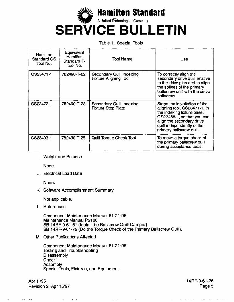
SERVICE BULLETIN Table 1. Special Tools
Hamilton Standard GS
Tool No.
I GS23471-1
GS23472-1
G S23493- 1 I-
Equivalent Hamilton
Standard T- Tool No.
782490-T-22
782490-T-23
782490-T-25
I
I. Weight and Balance
None. J. Electrical Load Data
Tool Name
Secondary Quill Indexing Fixture Aligning Tool
Secondary Quill Indexing Fixture Stop Plate
Quill Torque Check Tool
Use
To correctly align the secondary drive quill relative to the drive pins and to align the splines of the primary ballscrew quill with the servo ballscrew.
Stops the installation of the aligning tool, GS23471-1, in the indexing fixture base, GS23468-1, so that you can align the secondary drive quill independently of the primary ballscrew quill.
To make a torque check of the primary ballscrew quill during acceptance tests.
None. K. Software Accomplishment Summary
Not applicable. L. References
Component Maintenance Manual 61-21 -06 Maintenance Manual P5186 SB 14RF-9-61-61 (Install the Ballscrew Quill Damper) SB 14RF-9-61-75 (Do the Torque Check of the Primary Ballscrew Quill).
M. Other Publications Affected
Component Maintenance Manual 61-21 -06 Testing and Troubleshooting Disassembly Check Assembly Special Tools, Fixtures, and Equipment
Apr 1 /95 Revision 2 Apr 15/97
14RF-9-61-76 Page 5
Hamilton Standard A United Technologies Company
SERVICE BULLETIN Illustrated Parts List
Maintenance Manual P5186 Airworthiness Limitations Inspection/Check (Section 61 -1 0-00)
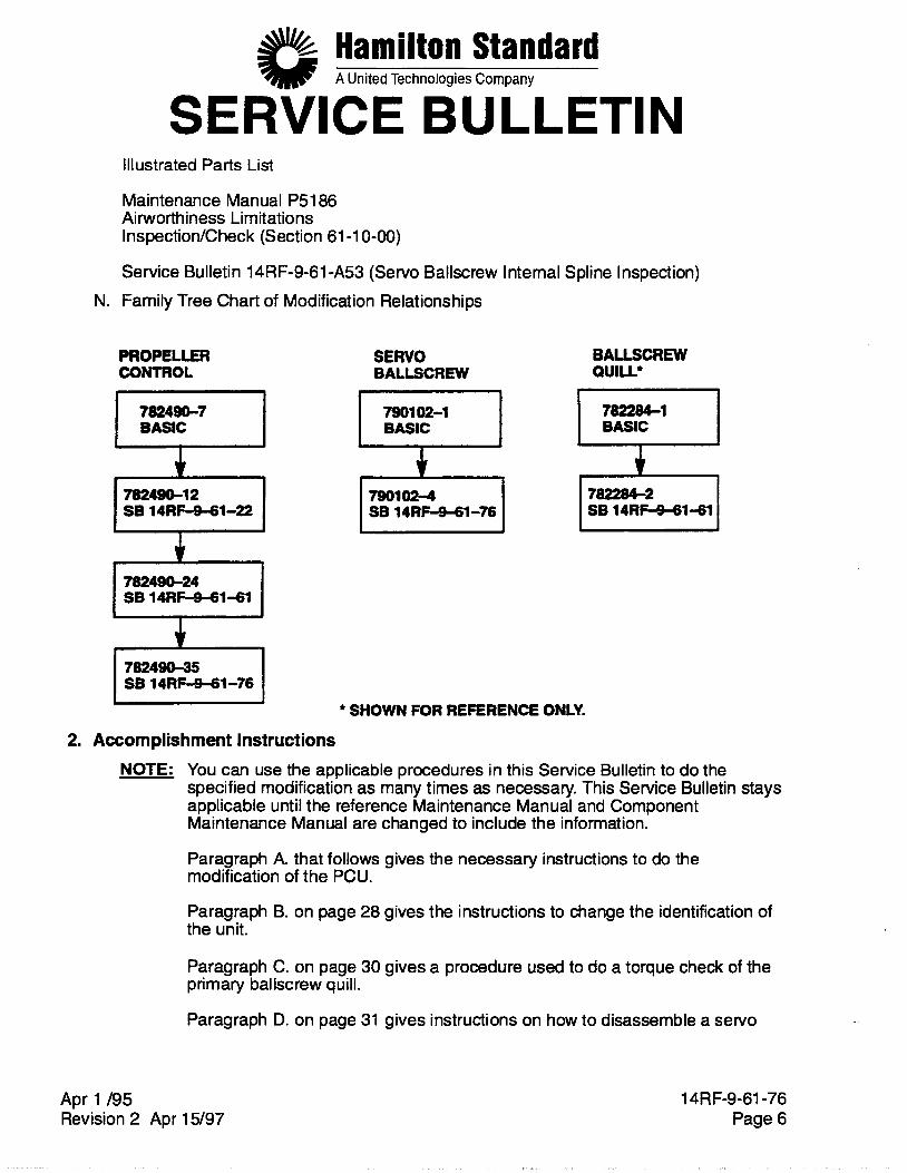
Service Bulletin 14RF-9-61 -A53 (Servo Ballscrew Internal Spline Inspection) N. Family Tree Chart of Modification Relationships
PROPELLER COMROL
SERVO BALLSCREW
BALLSCREW OUlLL*
BASIC
7024-12 SB 14RF-9-61-22 I I
I 78249b24 SB 1 4 R M 1 - 6 1 I
7901 02-1
SB 14RF-9-61-76 I I
I 782284-1 1 BASIC
782284-2 SB 1 4 R M 1 - 6 1
SB 14RF-941-76 PYlJ ' SHOWN FOR REFERENCE ONLY.
2. Accomplishment Instructions NOTE: You can use the applicable procedures in this Service Bulletin to do the
specified modification as many times as necessary. This Service Bulletin stays applicable until the reference Maintenance Manual and Component Maintenance Manual are changed to include the information.
Paragraph A. that follows gives the necessary instructions to do the modification of the PCU.
Paragraph B. on page 28 gives the instructions to change the identification of the unit.
Paragraph C. on page 30 gives a procedure used to do a torque check of the primary bal lscrew quill.
Paragraph D. on page 31 gives instructions on how to disassemble a servo
Apr 1 /95 Revision 2 Apr 15/97
14RF-9-61-76 Page 6
Hamilton Standard A United Technologies Company
SERVICE BULLETIN ballscrew that has the secondary drive quill installed.
Paragraph E. on page 32 gives instructions to complete the form at the end of this Service Bulletin.
A. Do the modification of the PCU as specified in the procedures that follow: CAUTION: WHEN YOU REMOVE THE DUPLEX BALL BEARING FROM THE SERVO
BALL SCREW, BE CAREFUL NOTTO LET THE BEARING COME APART. IF THE BEARING COMES APART YOU WILL HAVE TO REPLACE IT WITH A NEW BEARING.
(1) Disassemble the PCU to get to the servo ballscrew PN 790102-1. Remove the ballscrew quill (PN 782284-1 for PCU PN 782490-12, or PN 782284-2 for PCU PN 782490-12/8614RF-9-61-61 or PCU PN 782490-24) and duplex ball bearing PN 77571 8-2 from the ballscrew. Refer to the procedure for disassembly of the servo piston and sleeve groups in the reference Component Maintenance Manual for the instructions on how to do this. NOTE: PCU PN 782490-1 2/SB14RF-9-61-61 and PCU PN 782490-24 also have a
damper PN 814671 -1 and shims PN 81 3381 -1 thru -6 installed on the ballscrew quill PN 782284-2 (reference SB 14RF-9-61-61). Keep these parts together.
(2) If this modification is for PCU PN 782490-12 (not PN 782490-12/ SB14RF-9-61-61), you will need kit PN 27920 to include the damper modification (reference SB 14RF-9-61-61). Included in this kit is a new ballscrew quill PN 782284-2. Replace ballscrew quill PN 782284-1 with new PN 782284-2. Do not install the new ballscrew quill until you are told to do so.
(3) Make a modification of servo ballscrew PN 7901 02-1 to PN 7901 02-4 with the procedure that follows:
(a) Inspect the splines of servo ballscrew PN 7901 02-1 as follows: - 1 Inspect the splines for steps as specified in ASB14RF-9-61A53 but with the
changes that follow:
- a When you make a check of the right side of all 36 teeth, reject the servo ballscrew if you find steps on more than 12 teeth. If you find steps on 12 teeth or less, continue to make a check for steps on the left side of the teeth.
- b When you make a check of the left side of all 36 teeth, reject the servo ballscrew if you find steps on more than 12 teeth. If you find steps on 12 teeth or less, the servo ballscrew is serviceable.
2 f you find that the servo ballscrew is serviceable, you can continue to step (b) to make a modification of the ballscrew.
a If you find that the servo ballscrew is not serviceable, you must replace the ballscrew with a serviceable PN 7901 02-4 or PN 7901 02-4 made from PN 790102-1 by the instructions in this Service Bulletin or SK115747 and continue to step (4) on page 15.
Apr 1 /95 Revision 2 Apr 15/97
14RF-9-61-76 Page 7
Hamilton Standard A United Technologies Company
SERVICE BULLETIN (b) Remove the collar from the servo ballscrew as follows:
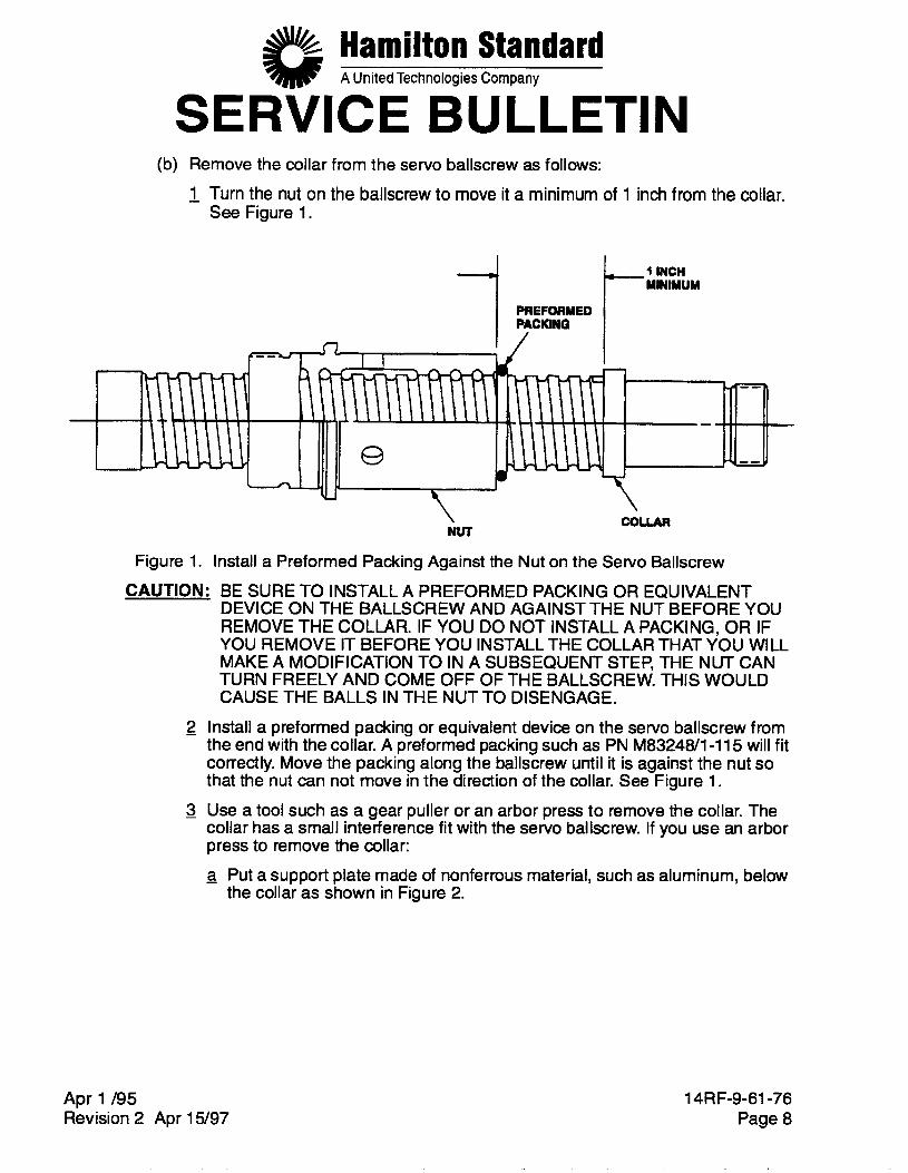
- 1 Turn the nut on the ballscrew to move it a minimum of 1 inch from the collar. See Figure 1.
\ NUT
-1 INCH MINIMUM
Figure 1. Install a Preformed Packing Against the Nut on the Servo Ballscrew
CAUTION: BE SURE TO INSTALL A PREFORMED PACKING OR EQUIVALENT DEVICE ON THE BALLSCREW AND AGAINST THE NUT BEFORE YOU REMOVE THE COLLAR. IF YOU DO NOT INSTALL A PACKING, OR IF YOU REMOVE IT BEFORE YOU INSTALL THE COLLAR THAT YOU WILL MAKE A MODIFICATION TO IN A SUBSEQUENT STEP, THE NUT CAN TURN FREELY AND COME OFF OF THE BALLSCREW. THIS WOULD CAUSE THE BALLS IN THE NUT TO DISENGAGE.
- 2 Install a preformed packing or equivalent device on the servo ballscrew from the end with the collar. A preformed packing such as PN M8324Wl-115 will fit correctly. Move the packing along the ballscrew until it is against the nut so that the nut can not move in the direction of the collar. See Figure 1.
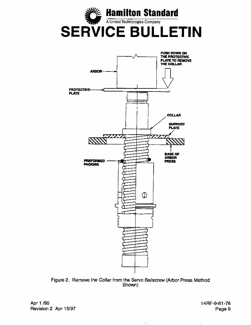
- 3 Use a tool such as a gear puller or an arbor press to remove the collar. The collar has a small interference fit with the servo ballscrew. If you use an arbor press to remove the collar: - a Put a support plate made of nonferrous material, such as aluminum, below
the collar as shown in Figure 2.
Apr 1 /95 Revision 2 Apr 15/97
14RF-9-61-76 Page 8
#& Hamilton Standard A United Technologies Company
SERVICE BULLETIN PUSH DOWN ON THE PROTECTWE PLATE TO REMOVE THECOUAR
AFtE#oFI--.--r( I n 1 I I V
PRO~CTIVC-~ PLATE I I
Figure 2. Remove the Collar from the Servo Ballscrew (Arbor Press Method Shown)
t BASEOF ARBOR PRESS
Apr 1 I95 Revision 2 Apr 15/97
14RF-9-61-76 Page 9
1 .
Hamilton Standard A United Technologies Company
SERVICE BULLETIN - b Put the servo ballscrew on the arbor press so that the support plate is on
the base of the arbor press. Put a protective plate of aluminum between the arbor and the ballscrew to give protection to the ballscrew.
CAUTION: BE SURE THAT THE BALLSCREW DOES NOT FALL THROUGH THE BASE OF THE ARBOR PRESS WHEN THE COLLAR IS REMOVED.
- c Carefully push on the protective plate at the end of the ballscrew with the
4 Remove the ballscrew from the arbor and remove the support plate. arbor to remove the collar.
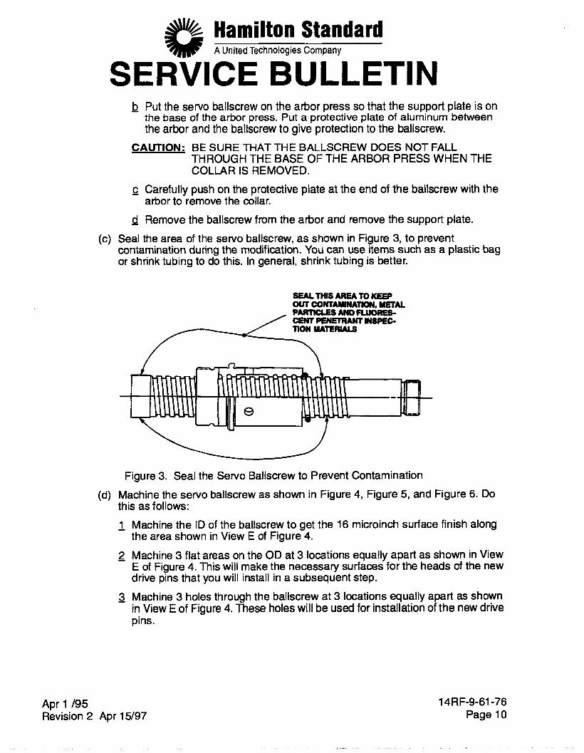
Seal the area of the servo ballscrew, as shown in Figure 3, to prevent contamination during the modification. You can use items such as a plastic bag or shrink tubing to do this. In general, shrink tubing is better.
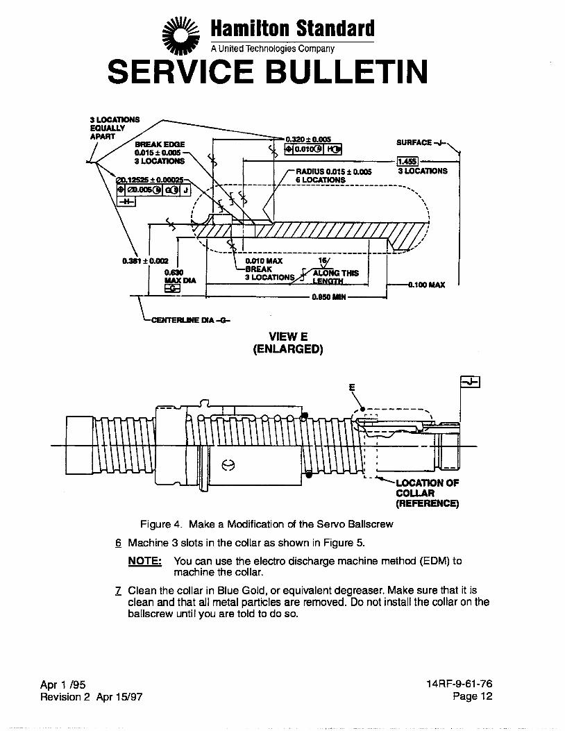
Figure 3. Seal the Servo Ballscrew to Prevent Contamination Machine the servo ballscrew as shown in Figure 4, Figure 5, and Figure 6. Do this as follows:
Machine the ID of the ballscrew to get the 16 microinch surface finish along the area shown in View E of Figure 4.
Machine 3 flat areas on the OD at 3 locations equally apart as shown in View E of Figure 4. This will make the necessary surfaces for the heads of the new drive pins that you will install in a subsequent step. Machine 3 holes through the ballscrew at 3 locations equally apart as shown in View E of Figure 4. These holes will be used for installation of the new drive pins.
Apr 1 195 Revision 2 Apr 15/97
14RF-9-61-76 Page 10
Hamilton Standard A United Technologies Company
SERVICE BULLETIN WARNING: USE GOGGLES AND RUBBER GLOVES WHEN YOU USE BLUE
GOLD. USE IT IN AN AREA WITH A GOOD FLOW OF AIR. IT CAN CAUSE IRRITATION TO YOUR EYES, SKIN AND RESPIRATORY TRACT.
Locally clean the machined area of the servo ballscrew in Blue Gold, or equivalent degreaser. Make sure that all metal particles and contamination are removed. Blue Gold is available from:
Modern Chemical, Inc. P.O. Box 368 Jacksonville, AR 72078
Phone: 501-988-1311 Do a fluorescent penetrant inspection of the machined areas for signs of cracks. Use Type I, sensitivity level 2, and method B or method D as specified in MIL-STD-6866 and MIL-1-251 35. If you do not find cracks, continue with step 6). If you find cracks, do not continue the modification of the servo ballscrew. Replace it with a new servo ballscrew PN 7901 02-4 or PN 7901 02- 4 made from PN 790102-1 by the instructions in this Service Bulletin or SK115747 and continue to step (4) on page 15.
Apr 1 /95 Revision 2 Apr 15/97
14RF-9-61-76 Page 11
Hamilton Standard A United Technologies Company
SERVICE BULLETIN
VIEW E (ENLARGED)
' - C"LOCATION OF COLLAR (REFERENCE)
Figure 4. Make a Modification of the Servo Ballscrew
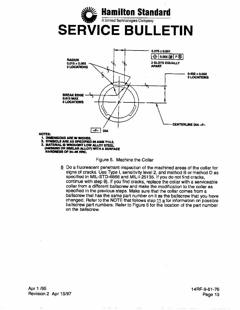
- 6 Machine 3 slots in the collar as shown in Figure 5. NOTE: You can use the electro discharge machine method (EDM) to
machine the collar. - 7 Clean the collar in Blue Gold, or equivalent degreaser. Make sure that it is
clean and that all metal particles are removed. Do not install the collar on the ballscrew until you are told to do so.
Apr 1 /95 Revision 2 Apr 15/97
14RF-9-61-76 Page 12
Hamilton Standard A United Technologies Company
SERVICE BULLETIN - 0.275 f 0.001
I + I O . ~ @ I F B I 3 SLOTS EOUAUY APART
0.432 f 0.002 3 LOCATIONS
aoio MAX I
CENTERLINE DIA -F-
3LocATKwsS
WA NOTES:
1. WENIONS ARE IN WCHES. z SYMBOLS ARE AS SPECIFIED IN ANSI Y14.5. 3. NATERuLIwRouaMLowMulYsTEu
(rurssz6s OR SIMILAR ALLOY) WITH A SURFACE HARONESS OF- HRC.
Figure 5. Machine the Collar - 8 Do a fluorescent penetrant inspection of the machined areas of the collar for
signs of cracks. Use Type I, sensitivity level 2, and method B or method D as specified in MIL-STD-6866 and MIL-1-251 35. If you do not find cracks, continue with step 9). If you find cracks, replace the collar with a serviceable collar from a different ballscrew and make the modification to the collar as specified in the previous steps. Make sure that the collar comes from a ballscrew that has the same part number on it as the ballscrew that you have changed. Refer to the NOTE that follows step 11 a for information on possible ballscrew part numbers. Refer to Figure 6 for the location of the part number on the ballscrew.
Apr 1 /95 Revision 2 Apr 15/97
14RF-9-61-76 Page 13
Hamilton Standard A United Technologies Company
SERVICE BULLETIN ADO THE SAME SERIAL NUMBER THAT IS FOUND ON THE NUT ON THIS UNO. ALSO, IF YOU FIND A SERJAL NUMBER THAT IS NOT THE W E AS THE ONE ON THE NUT, MAKE A W E THROUQH CT.
LOCATION OF PART ’ NUMBER AND SERIAL NUMBER ON THE NUT
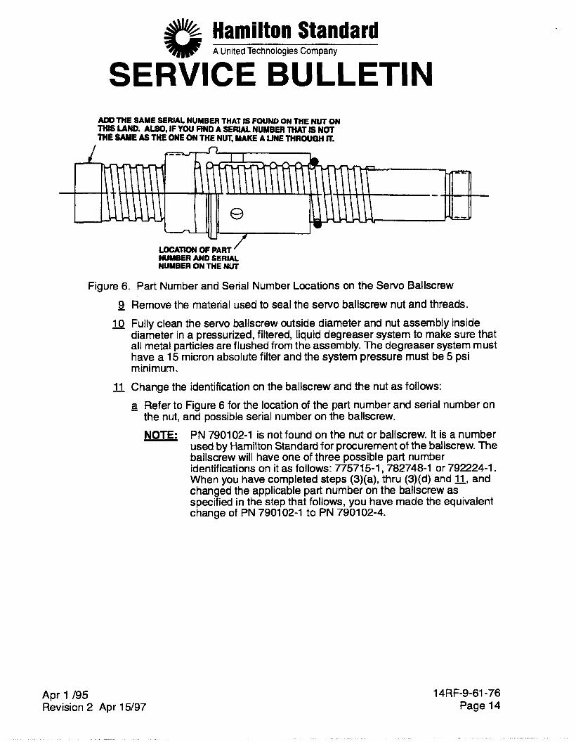
Figure 6. Part Number and Serial Number Locations on the Servo Ballscrew
9 - 10
- 11
Remove the material used to seal the servo ballscrew nut and threads. Fully clean the servo ballscrew outside diameter and nut assembly inside diameter in a pressurized, filtered, liquid degreaser system to make sure that all metal particles are flushed from the assembly. The degreaser system must have a 15 micron absolute filter and the system pressure must be 5 psi minimum.
Change the identification on the ballscrew and the nut as follows: 3 Refer to Figure 6 for the location of the part number and serial number on
PN 790102-1 is not found on the nut or ballscrew. It is a number used by Hamilton Standard for procurement of the ballscrew. The ballscrew will have one of three possible part number identifications on it as follows: 7757151,782748-1 or 792224-1. When you have completed steps (3)(a), thru (3)(d) and 11, and changed the applicable part number on the ballscrew as specified in the step that follows, you have made the equivalent change of PN 7901 02-1 to PN 7901 02-4.
the nut, and possible serial number on the ballscrew. NOTE:
Apr 1 /95 Revision 2 Apr 15/97
14RF-9-61-76 Page 14
Hamilton Standard A United Technologies Company
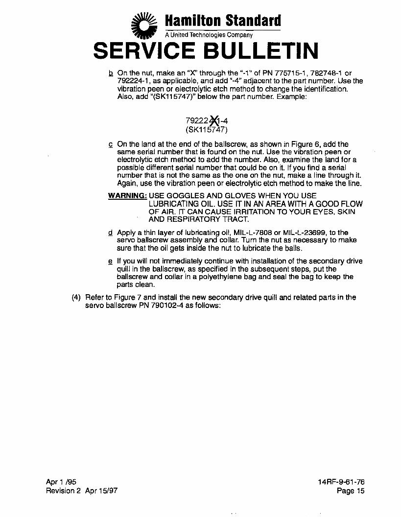
SERVICE BULLETIN - b On the nut, make an “ X through the “-1” of PN 77571 5-1, 782748-1 or
792224-1 , as applicable, and add “-4” adjacent to the part number. Use the vibration peen or electrolytic etch method to change the identification. Also, add “(SK115747)” below the part number. Example:
79222M-4 (SKI 15747)
- c On the land at the end of the ballscrew, as shown in Figure 6, add the same serial number that is found on the nut. Use the vibration peen or electrolytic etch method to add the number. Also, examine the land for a possible different serial number that could be on it. If you find a serial number that is not the same as the one on the nut, make a line through it. Again, use the vibration peen or electrolytic etch method to make the line.
LUBRICATING OIL. USE IT IN AN AREA WITH A GOOD FLOW OF AIR. IT CAN CAUSE IRRITATION TO YOUR EYES, SKIN AND RESPIRATORY TRACT.
WARNING: USE GOGGLES AND GLOVES WHEN YOU USE
- d Apply a thin layer of lubricating oil, MIL-L-7808 or MIL-L-23699, to the servo ballscrew assembly and collar. Turn the nut as necessary to make sure that the oil gets inside the nut to lubricate the balls.
- e If you will not immediately continue with installation of the secondary drive quill in the ballscrew, as specified in the subsequent steps, put the ballscrew and collar in a polyethylene bag and seal the bag to keep the parts clean.
(4) Refer to Figure 7 and install the new secondary drive quill and related parts in the servo ballscrew PN 790102-4 as follows:
Apr 1 /95 Revision 2 Apr 15/97
14RF-9-61-76 Page 15
#% Hamilton Standard A United Technologies Company
SERVICE BULLETIN
SECONDARY WILL INSTALIATION TOOL, osxuID-1
1
DRIVE PIN PN 606787-1 3 LOCATIONS
APPLY ONE DROP OF SEALANT HEREFOR EACH DRIVE PIN
/ /
NliT
SECONDARY
PN 617381-1 DRIVE auu
HWCAL SPRING PN 617362-1
SPACER
END W THE BALLSCREW WlTH THREADS (-EN-
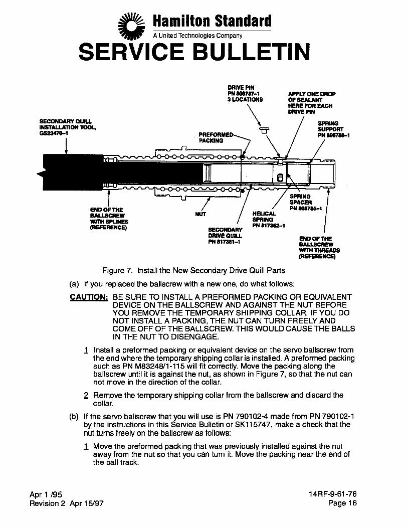
Figure 7. Install the New Secondary Drive Quill Parts
(a) If you replaced the ballscrew with a new one, do what follows: CAUTION: BE SURE TO INSTALL A PREFORMED PACKING OR EQUIVALENT
DEVICE ON THE BALLSCREW AND AGAINST THE NUT BEFORE YOU REMOVE THE TEMPORARY SHIPPING COLLAR. IF YOU DO NOT INSTALL A PACKING, THE NUT CAN TURN FREELY AND COME OFF OF THE BALLSCREW. THIS WOULD CAUSE THE BALLS IN THE NUT TO DISENGAGE.
Install a preformed packing or equivalent device on the servo ballscrew from the end where the temporary shipping collar is installed. A preformed packing such as PN M8324W1-115 will fit correctly. Move the packing along the ballscrew until it is against the nut, as shown in Figure 7, so that the nut can not move in the direction of the collar. Remove the temporary shipping collar from the ballscrew and discard the collar.
(b) If the servo ballscrew that you will use is PN 790102-4 made from PN 790102-1 by the instructions in this Service Bulletin or SK115747, make a check that the nut turns freely on the ballscrew as follows:
- 1 Move the preformed packing that was previously installed against the nut away from the nut so that you can turn it. Move the packing near the end of the ball track.
Apr 1 /95 Revision 2 Apr 15/97
14RF-9-61-76 Page 16
Hamilton Standard A United Technologies Company
SERVICE BULLETIN 2 Turn the nut a minimum of 3 full turns in both directions. Make sure that the
nut turns freely which shows that there are no metal particles or contamination in the nut remaining from the modification of the assembly.
- 3 If the nut does not turn freely, clean the nut again with a degreaser as specified in step 10 on page 14. Then, apply lubricating oil to the servo ballscrew assembly again, as specified in step on page 15.
Prepare the 3 new drive pins PN 808787-1 and the flat surfaces on the ballscrew for sealant, which you will apply in a subsequent step, as follows: WARNING: USE GOGGLES AND RUBBER GLOVES WHEN YOU USE LPS
NOFLASH CLEANER OR MEK. USE IT IN AN AREA WITH A GOOD FLOW OF AIR. IT CAN CAUSE IRRITATION TO YOUR EYES, SKIN, AND RESPIRATORY TRACT.
- 1 Clean the 3 new drive pins and the flat surfaces that they will touch on the ballscrew with LPS NoFlash Cleaner, MEK, or equivalent. Let the surfaces dry. LPS NoFlash Cleaner is available from:
Flagg Industrial Supply Co. 1041 State St. New Haven, CT 06530
Phone: 203-772-31 66 - 2 Apply a thin layer of Loctite Grade T primer below the heads and on the
stems of the drive pins with a brush. Let the primer dry for 10 minutes minimum. Loctite Grade T primer is available from:
Loctite Corporation 999 North Mountain RD Newington, CT 06111
Phone: 860-246-1223 NOTE: As an alternative to Loctite Grade T primer, you can use an
equivalent Grade T primer as specified in MIL-S-22473. CAUTION: BE SURE THATTHE SIDE OF THE SPRING SUPPORTTHAT
HAS A CHAMFER POINTS TO THE END OF THE BALLSCREW THAT HAS THREADS. IF YOU INSTALL THE SPRING SUPPORT IN THE OPPOSITE DIRECTION, THE SPRING FORCE WILL BE TOO HIGH.
Install the new spring support PN 808788-1 into the ballscrew through the end of the ballscrew that has internal splines (refer to Figure 7). The side of the spring support that has a chamfer must point to the end of the ballscrew that has threads. Install the new helical spring PN 817362-1 in the ballscrew followed by the new spring spacer PN 808785-1.
14RF-9-61-76 Page 17 Revision 2 Apr 15/97
Hamilton Standard A United Technologies Company
SERVICE BULLETIN (f) Install the new secondary drive quill PN 81 7381 -1 in the ballscrew so that the
end that has 3 slots for the drive pins is against the spring spacer PN 808785-1.
(9) Install the secondary quill installation tool, GS23470-1 (782490-T-21), in the ballscrew as shown in Figure 7. Turn and push on the tool to align the secondary drive quill so that you can install the 3 drive pins as follows:
- 1 Push on the installation tool to compress helical spring PN 817362-1. - 2 Turn the tool as necessary until the 3 slots in the secondary drive quill are
aligned with the 3 holes in the servo ballscrew. - 3 Install the 3 new drive pins PN 808787-1 in the ballscrew. The drive pins can
have a small interference fit with the ballscrew, but you should be able to push them in with your fingers. Make sure that the heads of the drive pins are against the flats on the ballscrew.
- 4 Remove the installation tool.
(h) Seal the 3 drive pins as follows: - 1 Apply one small drop of sealant, Loctite 290, to the area between the head of
each of the 3 drive pins and the flat surface that they touch on the ballscrew, as shown in Figure 7. Loctite 290 is available from:
Loctite Corporation. NOTE: As an alternative to Loctite 290, you can use an equivalent sealant
as specified in MIL-S-46163, Type Ill, Grade R. WARNING: USE GOGGLES AND RUBBER GLOVES WHEN YOU USE LPS
NOFLASH CLEANER OR MEK. USE IT IN AN AREA WITH A GOOD FLOW OF AIR. IT CAN CAUSE IRRITATION TO YOUR EYES, SKIN, AND RESPIRATORY TRACT.
- 2 After 15 to 20 minutes, remove unwanted sealant with a clean cloth moist
3 Use one of the methods, step a) or b) that follows, to cure the sealant: with LPS NoFlash Cleaner, MEK, or equivalent
a Let the sealant dry for 6 hours minimum at room temperature. WARNING: USE GLOVES WITH INSULATION IN THEM WHEN YOU
TOUCH PARTS THAT ARE HOT. WITHOUT PROTECTION, HOT PARTS CAN CAUSE YOUR SKIN TO BURN.
- b Put the assembly in an oven at 212 10°F so that the sealed area is at this temperature for 30 minutes minimum. Then remove the assembly from the oven and let it cool to room temperature.
(5) Install the collar on the ballscrew as follows:
(a) Use an arbor press to install the collar as follows: - 1 Put the collar on the ballscrew and align the 3 slots in the collar with the
heads of the 3 drive pins.
Apr 1 /95 Revision 2 Apr 15/97
14RF-9-61-76 Page 18
Hamilton Standard A United Technologies Company
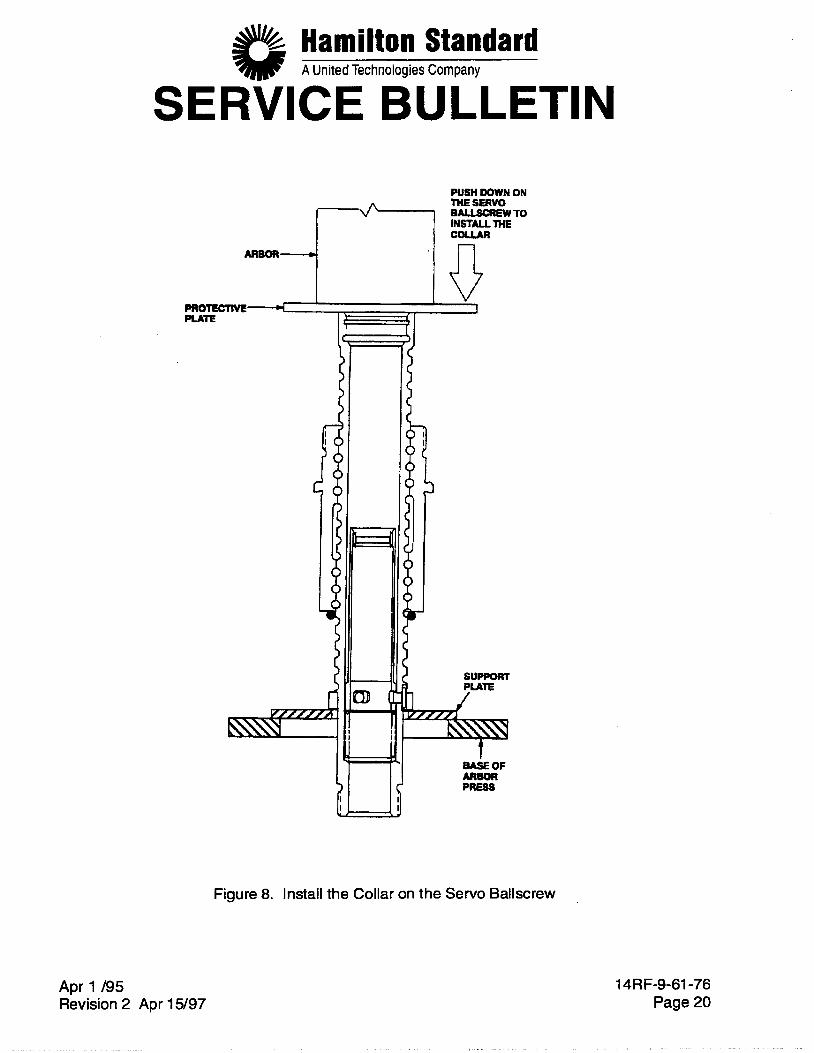
SERVICE BULLETIN - 2 While you hold the collar in this position, turn the ballscrew so that the end
- 3 Put a nonferrous support plate below the collar as shown in Figure 8. - 4 Put the servo ballscrew on the arbor press so that the support plate is on the
- 5 Put a protective plate of aluminum between the arbor and the ballscrew to
- 6 Carefully push on the protective plate at the end of the ballscrew with the
with the threads is down.
base of the arbor press.
give protection to the ballscrew.
arbor to push the collar on the ballscrew. The collar must be fully against the remaining shoulder at the end of the ball track.
- 7 Remove the ballscrew from the arbor press and remove the support plate.
Apr 1 195 Revision 2 Apr 15/97
14RF-9-61-76 Page 19
Hamilton Standard A United Technologies Company
SERVICE BULLETIN PUSH DOWN ON THE SERVO BALLsuEwTO INSTALLTHE
.
ARBOR-
PRoTEcTIyE4- Pun
Apr 1 /95 Revision 2 Apr 15/97
t
7-
b J
SUPPORT PUTE
BA& OF ARBOR PRESS
Figure 8. Install the Collar on the Servo Ballscrew
14RF-9-61-76 Page 20
Hamilton Standard A United Technologies Company
SERVICE BULLETIN (b) Remove the preformed packing or other device that you previously installed on
the ballscrew against the nut. If you installed a preformed packing, put this packing in an envelope, or equivalent, and give it special identification. This packing is similar to the preformed packing PN 814671-1 used for the damper, but it must not be used for the damper.
Install the servo ballscrew assembly in the PCU. Refer to the Component Maintenance Manual for the instructions on how to do this. Do not install the primary ballscrew quill PN 782284-2 until you are told to in a subsequent step. Refer to SB 14RF-9-61-61 (Install the Ballscrew Quill Damper) and do what follows:
Do the procedure to find the necessary shims PN 81 3381 -1 thru -6 to fill the gap between the primary ballscrew quill PN 782284-2 and the damper PN 814671 -1. For PCU 782490-1 USB14RF-9-61-61 or PCU PN 782490-24, which previously had a damper installed, you do not have to calculate the necessary shims again if you did not replace the primary ballscrew quill or the servo ballscrew or the damper and you are sure that the same quill, damper, shims, and ballscrew were kept together with the PCU. For PCU PN 782490-lZSB14RF-9-61-61 or PCU PN 782490-24, visually examine the damper and shims that were installed in the PCU. If they are not damaged, you can use them again. If they are damaged, replace them. If you replace the damper, you must calculate the necessary shims again as specified in the reference Service Bulletin.
CAUTION: BE CAREFUL WHEN YOU MOVE THE DAMPER ALONG THE THREADS OF THE SERVO BALLSCREW TO PREVENT DAMAGE TO THE DAMPER. THE EDGES OF THE THREADS CAN BE SHARP AND CAN CUT THE DAMPER.
Apply the specified lubricant to the damper and temporarily install it on the OD of the ballscrew. Carefully move the damper along the ballscrew until it is 2 to 3 threads from the end of the ballscrew from which you installed it. This will prevent interference of the damper with the secondary quill indexing fixture base, GS23468-1, when you install the PCU in the fixture base in a subsequent step Install the shims on the primary ballscrew quill PN 782284-2.
Install a new retainer wire PN 778791-1 on the primary ballscrew quill. Align the primary ballscrew quill and the secondary drive quill as follows:
Install the PCU on power arm fixture assembly, GS20383-1 (775750-T-14). Install the secondary quill indexing fixture base, GS23468-1 (782490-T-19), on the power arm fixture assembly as shown in Figure 9. Attach the base to the power arm with the two bolts and washers that are supplied with the base. NOTE: Make sure that the indexing fixture base is installed tightly against the
power arm fixture assembly.
Apr 1 /95 Revision 2 Apr 15/97
14RF-9-61-76 Page 21
Hamilton Standard A United Technologies Company
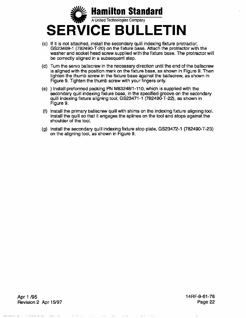
SERVICE BULLETIN (c) If it is not attached, install the secondary quill indexing fixture protractor,
GS23469-1 (782490-T-20) on the fixture base. Attach the protractor with the washer and socket head screw supplied with the fixture base. The protractor will be correctly aligned in a subsequent step.
(d) Turn the servo ballscrew in the necessary direction until the end of the ballscrew is aligned with the position mark on the fixture base, as shown in Figure 9. Then tighten the thumb screw in the fixture base against the ballscrew, as shown in Figure 9. Tighten the thumb screw with your fingers only.
secondary quill indexing fixture base, in the specified groove on the secondary quill indexing fixture aligning tool, GS23471-1 (782490-T-22), as shown in Figure 9.
(f) Install the primary ballscrew quill with shims on the indexing fixture aligning tool. Install the quill so that it engages the splines on the tool and stops against the shoulder of the tool.
(9) Install the secondary quill indexing fixture stop plate, GS23472-1 (782490-T-23) on the aligning tool, as shown in Figure 9.
(e) ) Install preformed packing PN M83248/1-110, which is supplied with the
Apr 1 /95 Revision 2 Apr 15/97
14RF-9-61-76 Page 22
Hamilton Standard A United Technologies Company
SERVICE BULLETIN THE DRIVE PINS MUST BE JN THE CENTER OF THESE SLOTS IN THE SECONDARY
ORWE au'u 1
WASHER 2LocATK)Ns (SUPPED WlTH FMTURE)
\
VIEW A-A ENLARGED
SOCKETHW SCREW 2 LOCATIONS
PACKlNG PN M8321M-110 (SUPPLED WlTH
Figure 9. Align the Primary Ballscrew Quill and the Secondary Drive Quill
Apr 1 /95 Revision 2 Apr 15/97
14RF-9-61-76 Page 23
Hamilton Standard A United Technologies Company
SERVICE BULLETIN (h) Install the aligning tool in the indexing fixture with the indicator arm aligned with
the protractor markings and engage the splines of the tool with the internal splines of the secondary drive quill. Then push the tool fully in until the stop plate is against the fixture base. NOTE: The aligning tool engages only with the secondary drive quill and the
primary quill. The primary quill external teeth do not yet engage the ballscrew internal splines.
CAUTION: MAKE SURE THAT THE BALLSCREW DOES NOT TURN WHEN YOU TURN THE ALIGNING TOOL TO PREVENT INCORRECT ALIGNMENT
Apr 1 /95
OF THE SECONDARY DRIVE QUILL.
Tum the aligning tool clockwise until the tool stops. The tool stops when one side of the slots in the secondary drive quill touch the drive pins.
While you keep the aligning tool in this position, loosen the screw that attaches the protractor. Turn the protractor until the position indicator bar is aligned with the 0" mark on the protractor. Then tighten the screw. Turn the aligning tool counterclockwise until it stops. The tool stops when the opposite side of the slots in the secondary drive quill touch the drive pins. The full travel of the tool from one stop to the opposite stop is approximately 24" Read the angle on the protractor where the position indicator bar has stopped. Divide this angle by 2. Turn the aligning tool clockwise to the angle that you calculated in step (I). This puts the secondary drive quill in a position where the pins are in the center of the slots in the quill and the quill is not engaged with the servo ballscrew. See Section A-A in Figure 9. Look through the bottom of the PCU with a light and make sure that the pins do not touch the sides of the slots in the quill.
While you keep the aligning tool in position, align the primary ballscrew quill with the secondary drive quill as follows:
- 1 Remove the stop plate from the aligning tool. - 2 Push the aligning tool fully in the indexing fixture base so that the external
splines on the primary ballscrew quill engage the internal splines in the servo ballscrew. If the splines do not engage, lightly push on the aligning tool while you turn the tool 1" clockwise, 2" counterclockwise, 3 " clockwise, 4" counterclockwise, as necessary, until the splines of the primary ballscrew quill engage the servo ballscrew. If the spline engagement point is greater than 2" from the center point, you must try to do the realignment procedure again. Do what follows: - a Raise the alignment tool and the primary quill until the primary quill internal
h Disengage the primary quill spline from the alignment tool and then rotate spline can be disengaged.
the quill in the direction of the center point (approximately 1 tooth per degree of misalignment).
- c Re-engage the alignment tool spline.
14RF-9-61-76 Revision 2 Apr 15/97 Page 24
Hamilton Standard A United Technologies Company
(9)
(11)
Apr 1 /95 Revision 2
SERVICE BULLETIN - d ) Reinstall the alignment tool and the primary quill assembly into the
secondary drive quill. As you do this, keep the alignment tool at the center point location.
splines engage the ballscrew splines. You can rotate the alignment tool slightly to permit engagement.
f Make a check of the alignment tool location. The alignment tool must be with 2" of the center point when the splines are engaged.
g If the alignment tool is more than 2" from the center point you must repeat the realignment procedure.
- e Continue to install the alignment tool so that the primary quill external
(0) Remove the PCU from the indexing fixture base as follows: ) Hold the primary ballscrew quill in position through the opening in the fixture base. Be sure to keep the quill in this position while you do the subsequent steps. Remove the aligning tool. If the primary quill disengages, go to step (h) on page 24 and do the alignment procedure again.
Loosen the thumbscrew in the fixture base. Remove the fixture base from the power arm fixture.
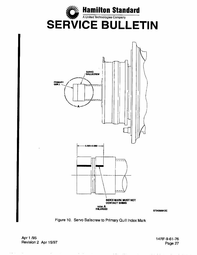
Complete the installation of the primary ballscrew quill and the damper and do a pull check on the quill as specified in SB 14RF-9-61-61. Make an index mark on the OD of the servo ballscrew and the OD of the ballscrew primaty quill as follows: (a) The mark must be 0.300 f 0.050 inch long. See Figure 10.
CAUTION: DO NOT PERMIT THE VIBRA-PEEN OR ENGRAVING TOOL TO TOUCH THE SHIMS BECAUSE THIS MAY DAMAGE THE SHIMS.
(b) The mark must not contact the shims between the ballscrew and the quill. (c) Make the index mark per one of the methods that follows:
1 Vibration peening. - 2 Engraving (0.003 to 0.01 0 inch deep). - 3 Laser (non stress raiser).
Before you move the PCU to the area where tests are to be done, install the secondary quill shipping fixture, GS23467-1 (338X-21), in the primary ballscrew quill, as shown in Figure 11. For this type of local movement of the PCU, you do not have to use the tie wraps, MS3367-2-4, or equivalent, to attach the shipping fixture to the PCU. You can use other equivalent alternatives to temporarily attach the shipping fixture. Do not remove the shipping fixture until you are prepared to do the tests.
Apr 15/97 14RF-9-61-76
Page 25
Hamilton Standard A United Technologies Company
SERVICE BULLETIN (12) Do all necessary tests of the PCU as specified in the TESTING AND
TROUBLESHOOTING section of the reference Component Maintenance Manual. The tests must include the new toque check of the primary ballscrew quill that is given in paragraph C. on page 30.
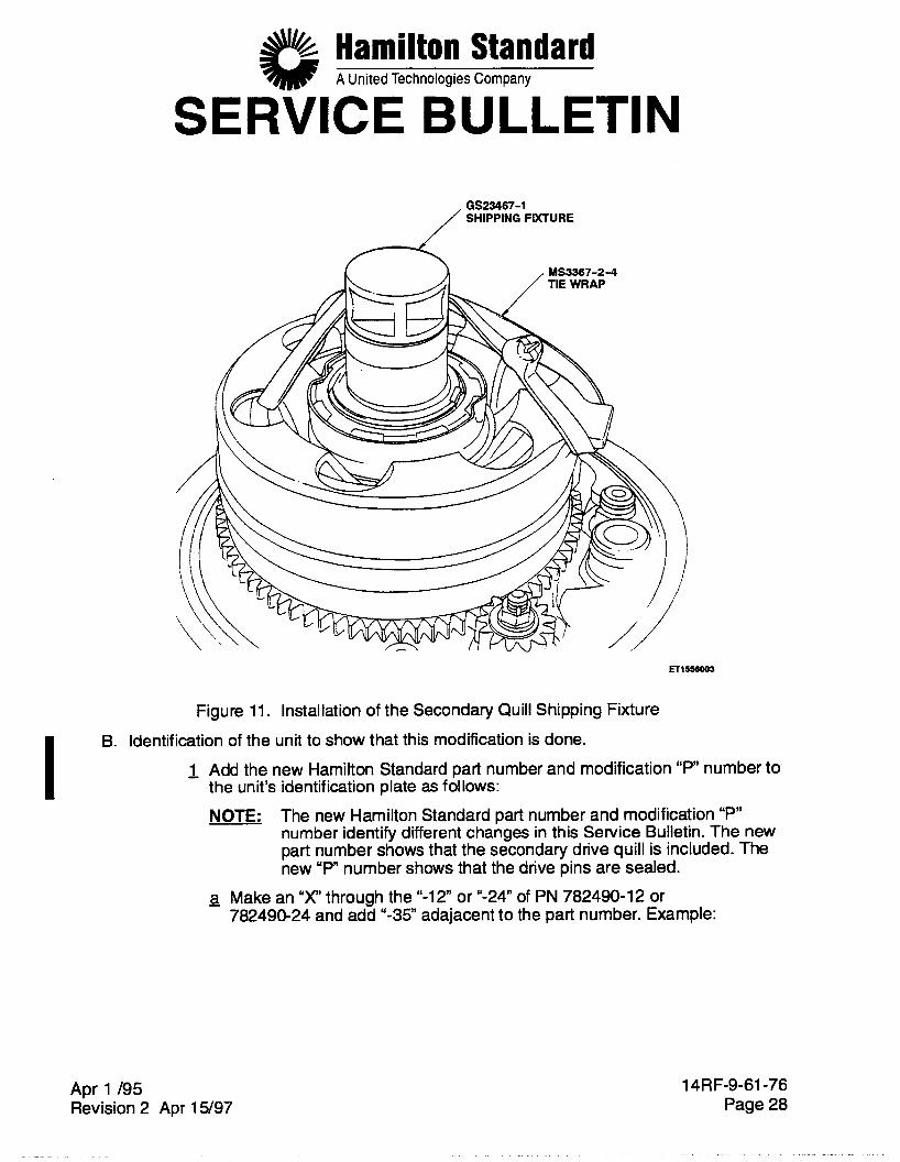
GS23467-1 (338X-21), in the primary ballscrew quill and attach it to the PCU with tie wraps MS3367-2-4, or equivalent, as shown in Figure 11. Always install the shipping fixture when you will not do tests on the PCU immediately after repair, when the PCU will be put in storage, or when you move or send the unit to the operator or to another location.
(13) After all tests are completed, again install the secondary quill shipping fixture,
Apr 1 /95 Revision 2 Apr 15/97
14RF-9-61-76 Page 26
Hamilton Standard A United Technologies Company
SERVICE BULLETIN
SERVO /BALLSCREW 1
INDEX MARK MUST NOT CONTACT SHIMS
VIEW A ENLARGED
Figure 10. Servo Ballscrew to Primary Quill Index Mark
Apr 1 /95 Revision 2 Apr 15/97
14RF-9-61-76 Page 27
Hamilton Standard A United Technologies Company
SERVICE BULLETIN GS23467-1 SHIPPING FIXTURE
, YS3367-24
Figure 11. Installation of the Secondary Quill Shipping Fixture B. Identification of the unit to show that this modification is done.
- 1 Add the new Hamilton Standard part number and modification " P number to the unit's identification plate as follows: NOTE: The new Hamilton Standard part number and modification "P"
number identify different changes in this Service Bulletin. The new part number shows that the secondary drive quill is included. The new "P" number shows that the drive pins are sealed.
a Make an "X' through the "-12 or "-24" of PN 782490-12 or 782490-24 and add "-35" adajacent to the part number. Example:
Apr 1 /95 Revision 2 Apr 15/97
14RF-9-61-76 Page 28
Hamilton Standard A United Technologies Company
SERVICE BULLETIN 782490x 2-35 or 782490x4-35
- b Add the dash number of the new part number followed by the new modification number “P2”. Example:
-35 P2
NOTE: The propeller control and adapter part number also changes from 784770-3 or 784770-4 to 784770-5 to identify the secondary drive quill installation, and new modification number “PZ‘ identifies that the drive pins are sealed. But these numbers do not show on the identification plate and are for information only.
- 2 Apply a yellow mark to the main housing as follows:
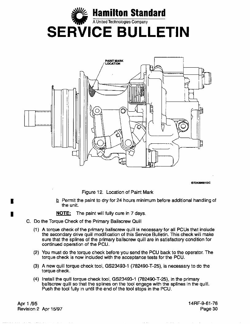
a Use primer paint (yellow), MIL-P-85582, Type I , Class 1A or 1 B, to make an approximate 1.00 inch diameter mark on the external surface of the main housing. See Figure 12.
Apr 1 /95 Revision 2 Apr 15/97
14RF-9-61-76 Page 29
Hamilton Standard A United Technologies Company
SERVICE BULLETIN
Figure 12. Location of Paint Mark - b Permit the paint to dry for 24 hours minimum before additional handling of
the unit. I I NOTE: The paint will fully cure in 7 days.
C. Do the Torque Check of the Primary Ballscrew Quill (1) A torque check of the primary ballscrew quill is necessary for all PCUs that include
the secondary drive quill modification of this Service Bulletin. This check will make sure that the splines of the primary ballscrew quill are in satisfactory condition for continued operation of the PCU.
(2) You must do the torque check before you send the PCU back to the operator. The torque check is now included with the acceptance tests for the PCU.
(3) A new quill torque check tool, GS23493-1 (782490-T-25), is necessary to do the torque check.
(4) Install the quill torque check tool, GS23493-1 (782490-T-25), in the primary ballscrew quill so that the splines on the tool engage with the splines in the quill. Push the tool fully in until the end of the tool stops in the PCU.
Apr 1 /95 Revision 2 Apr 15/97
14RF-9-61-76 Page 30
Hamilton Standard A United Technologies Company
SERVICE BULLETIN (5) Turn the handle of the tool fully clockwise until it stops to make sure that the PCU is
against its feather stop. The clockwise direction is in relation to the PCU when you look at the primary ballscrew quill.
CAUTION: DO NOT APPLY MORE THAN THE SPECIFIED TORQUE IN THE SUBSEQUENT STEP TO PREVENT DAMAGE TO THE PITCH CHANGE HARDWARE.
Put a torque wrench on the head of the hex head bolt of the quill torque check tool. Apply a torque of 20 f 5 pound-inches in the clockwise direction. The quill torque check tool must not turn. Decrease the torque to zero. Remove the torque wrench and the quill torque check tool. If the quill torque check tool did not turn when you applied the torque, the condition of the hardware +in the primary pitch change path is satisfactory. Continue to step (9). If the quill torque check tool did turn when you applied the torque, the condition of the hardware in the primary pitch change path is not satisfactory. Disassemble the PCU and make an inspection of the splines of the primary ballscrew quill, the splines of the servo ballscrew, and the retainer wire. Then, do step (a) or (b) that follows, as applicable:
(a) If this is the initial modification of the PCU and the inspection of the hardware is not satisfactory, replace the retainer wire and those parts that were rejected by the inspection. Use the disassembly procedure in paragraph D. that follows to disassemble the secondary drive quill. Then go to step (4) on page 15 to assemble the servo ballscrew again
(b) f the PCU previously had a secondary drive quill installed, the unit was operated on an aircraft, and the inspection of the hardware is not satisfactory, replace the primary ballscrew quill, servo ballscrew, secondary drive quill, spring spacer, spring support, helical spring, and the 3 drive pins. Then go to step (4) on page 15 to assemble the servo ballscrew again.
Continue with the necessary process procedures for the PCU. D. Procedure to Disassemble the Servo Ballscrew PN 7901 02-4 with the Secondary Drive
Quill Installed (1) If a PCU with a secondary drive quill installed needs to be disassembled for
inspection, disassemble the servo ballscrew PN 7901 02-4 as follows: Remove the collar. Refer to the procedure in paragraph (b) on page 8. Install the secondary quill installation tool, GS23470-1 (782490-T-21), in the end of the ballscrew that has splines. Push on the tool to compress the spring in the ballscrew. Remove the 3 drive pins PN 808787-1 from the ballscrew. You can use a thin blade tool to get below the head of the pins to help remove them. Remove the secondary quill installation tool.
Apr 1 195 Revision 2 Apr 15/97
1 .
14RF-9-61-76 Page 31
Hamilton Standard A United Technologies Company
NewPN
SERVICE BULLETIN
Estimated Key Word PN Before Instruction Price this SB Code Qty MSQ
(d) Remove these parts from the ballscrew: secondary drive quill PN 817381 -1 I
spring spacer PN 808785-1 , helical spring PN 81 7362-1 I and spring support PN 808788-1.
WARNING: USE GLOVES WITH INSULATION IN THEM WHEN YOU TOUCH PARTS THAT ARE HOT. WITHOUT PROTECTION, HOT PARTS CAN CAUSE YOUR SKIN TO BURN.
(e) To remove the sealant from the ballscrew and drive pins, put these parts in an oven at approximately 300” F for 30 minutes to make the sealant soft. Then use a scraper with a smooth edge that will not damage the parts to remove the sealant.
E. Complete the Secondary Drive Quill Installation Form
(1) Complete the form on the last page of this Service Bulletin for each PCU that gets the secondary drive quill modification.
(2) Send the completed form to us as specified on the form. 3. Material Information
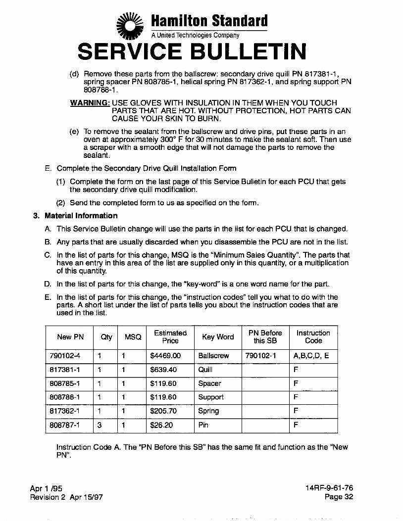
A. This Service Bulletin change will use the parts in the list for each PCU that is changed. 6. Any parts that are usually discarded when you disassemble the PCU are not in the list. C. In the list of parts for this change, MSQ is the “Minimum Sales Quantity”. The parts that
have an entry in this area of the list are supplied only in this quantity, or a multiplication of this quantity.
D. In the list of parts for this change, the “key-word” is a one word name for the part. E. In the list of parts for this change, the “instruction codes” tell you what to do with the
parts. A short list under the list of parts tells you about the instruction codes that are used in the list.
7901 02-4
81 7381 -1
808785- 1
1 1 $4469.00 Ballscrew 7901 02-1 A,B,C,Dl E
1 1 $639.40 Quill F
1 1 $1 19.60 Spacer F
808788-1
817362-1
808787-1
1 1 $1 19.60 support F
1 1 $205.70 Spring F
3 1 $26.20 Pin F I I I I I I I 1
Instruction Code A. The “PN Before this SB” has the same fit and function as the “New PN”.
Apr 1 /95 Revision 2 Apr 15/97
14RF-9-61-76 Page 32
Hamilton Standard A United Technologies Company
SERVICE BULLETIN Instruction Code B. The “PN Before this SB” is superseded by the “New PN”.
Instruction Code C. You can not continue to buy the “PN Before this SB.”
Instruction Code D. You can use the instructions in this Service Bulletin to make the “New PN” from the “PN Before this SB.
Instruction Code E. Identify the part as the Accomplishment Instructions tell you.
Instruction Code F. The “New PN” is an added part.
Hamilton Standard Internal Reference Number EC235669.
Hamilton Standard Internal Identification Number 14RF96176.
Apr 1 /95 Revision 2 Apr 15/97
14RF-9-61-76 Page 33
Hamilton Standard A United Technologies Company
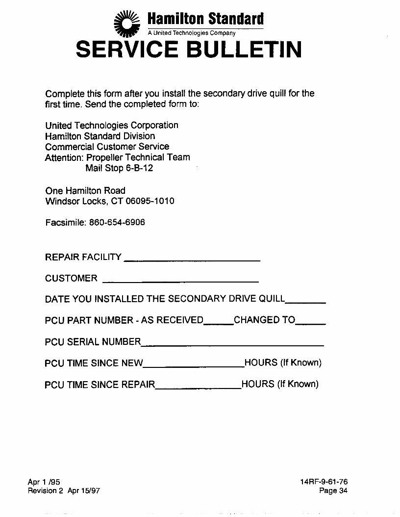
SERVICE BULLETIN Complete this form after you install the secondary drive quill for the first time. Send the completed form to:
United Technologies Corporation Hamilton Standard Division Commercial Customer Service Attention : Pro pel le r Tech n ica I Team
Mail Stop 6-B-12
One Hamilton Road Windsor Locks, CT 06095-1 01 0
Facsimile: 860-654-6906
REPAIR FACILITY
CUSTOMER
DATE YOU INSTALLED THE SECONDARY DRIVE QUILL
PCU PART NUMBER -AS RECEIVED CHANGED TO
PCU SERIAL NUMBER
PCU TIME SINCE NEW HOURS (If Known)
PCU TIME SINCE REPAIR HOURS (If Known)
Apr 1 /95 Revision 2 Apr 15/97
14RF-9-61-76 Page 34


![Ballscrew 3020-3040 Cnc Router GUIDE[1]](https://img.pdfslide.net/doc/110x75/55cf9758550346d033911b17/ballscrew-3020-3040-cnc-router-guide1.jpg)