Embed Size (px)
Citation preview

International Journal of Solids and Structures 128 (2017) 11–22 Contents lists available at ScienceDirect
International Journal of Solids and Structures journal homepage: www.elsevier.com/locate/ijsolstr
Band gap tunability in deformable dielectric composite plates Roey Getz, Gal Shmuel ∗Faculty of Mechanical Engineering, Technion–Israel Institute of Technology, Haifa 320 0 0, Israel a r t i c l e i n f o Article history: Received 1 May 2017 Revised 6 July 2017 Available online 26 July 2017 Keywords: Dielectric elastomer film Wave propagation Band gap Composite Phononic crystal Plane wave expansion Nonlinear elasticity
a b s t r a c t Subject to voltage, dielectric elastomers deform and stiffen. We show that harmonic excitations at cer- tain frequencies cannot propagate in incompressible dielectric elastomer fiber composite films . Impor- tantly, we demonstrate that these band gaps are tunable by the voltage. To show this, we formulate the equations governing small-amplitude waves in a deformed film, taking into consideration its surfaces. We develop a scheme to numerically solve the resultant equations, based on the supercell plane wave expansion method. To arrive at the findings above, we apply our scheme to a composite with circular fibers, and parametrically study the propagation dependency on the phase properties, film thickness, and voltage. Our results are another step towards the use of soft dielectric films as active wave manipulators.
© 2017 Elsevier Ltd. All rights reserved.
1. Introduction Mechanical waves traveling through elastic composites en-
counter periodic boundaries, which create secondary waves and, in turn, an interference pattern. This interference prevents the prop- agation of waves at particular frequency intervals, referred to as Bragg band gaps ( Sigalas and Economou, 1992; Kushwaha et al., 1993; Hussein et al., 2014 ). Therefore, elastic composites exhibit- ing band gaps can potentially protect from undesired vibrations ( Wen et al., 2005; Matlack et al., 2016 ) and filter noise ( Vasseur et al., 2002; Babaee et al., 2016; Bortot and Shmuel, 2017 ). Since in the process described, energy is redirected rather than dissi- pated, such composites can have additional functionalities includ- ing wave steering and energy tunneling ( Srivastava, 2016; Zelhofer and Kochmann, 2017; Ganesh et al., 2017 ).
The band gap structure depends on the physical and geometri- cal properties of the composite. Therefore, the functionally of pas- sive composites, which were initially studied and whose character- istics are fixed, is fixed too. To achieve adaptive functionalities, ac- tive composite, whose characteristics are tunable by external stim- uli, were later on investigated. Specifically, we recall active com- posites which are tunable by deformation and mechanical instabil- ities ( Bertoldi and Boyce, 2008; Shim et al., 2015; Shmuel and Band, 2016; Barnwell et al., 2017 ); magnetic stimulus ( Matar et al., 2012; Bayat and Gordaninejad, 2015 ); electric loads ( Beck et al., 2011; De- graeve et al., 2015; Shmuel and Salomón, 2016; Celli et al., 2017 );
∗ Corresponding author. E-mail addresses: [email protected] , [email protected] (G. Shmuel).
and thermal tuning ( Ruzzene and Baz, 1999; Jim et al., 2009 ). In this work, we investigate composites made of dielectric elastomer films ( Pelrine et al., 20 0 0; Carpi et al., 2010; Cohen and deBotton, 2016 ), owing to their simple working principle, low cost, fast re- sponse, and ability to experience significant geometrical and phys- ical changes.
Specifically, we consider a film made of two dielectric elastomer phases, which is quasi-statically activated by applying voltage to a pair of compliant electrodes coating its upper and lower surfaces. In the process, opposite charges accumulate on the electrodes, and the resultant Coulomb force between these charges squeezes the film along its thickness, while the elastomer phases stiffen. On top of the deformed configuration, we examine the propagation of in- cremental waves, while accounting for the reflections at the upper and lower surfaces; in terms of the mechanics terminology—we ex- amine plate or Rayleigh–Lamb modes in the actuated film. Since the actuation changes the geometry and the stiffness of the film, it will change the propagation characteristics ( Shmuel et al., 2012 ). Partic- ularly, it is expected that the actuation will change the range of the gaps. Our objective is to show that indeed the gaps are tun- able, and to study how the interplay between the voltage and the physical properties and thickness of the film affects this tunability. Thereby, this paper continues a series of works on tunable band gaps in dielectric elastomer composites; from gaps in the (i) thick- ness modes of laminates ( Shmuel and deBotton, 2012 ), through (ii) bulk anti-plane ( Shmuel, 2013 ) and (iii) bulk in-plane modes of fiber composites ( Getz et al., 2017 ), to Lamb modes in this paper.
The stages of this work are presented in the following order. Firstly, a framework to analyze the dynamics of deformable dielec-
http://dx.doi.org/10.1016/j.ijsolstr.2017.07.021 0020-7683/© 2017 Elsevier Ltd. All rights reserved.
12 R. Getz, G. Shmuel / International Journal of Solids and Structures 128 (2017) 11–22 tric composites 1 is reviewed in Section 2 ( Toupin, 1963; McMeek- ing and Landis, 2005; deBotton et al., 2007; Zhao and Suo, 2010; Dorfmann and Ogden, 2010; Pamies, 2014 ). This theory is spe- cialized in Section 3 , to develop the equations governing small- amplitude waves in a composite film of finite thickness, which was electrostatically deformed. The derived coupled differential equa- tions cannot be solved analytically. To obtain numerical solutions, we formulate a variation of the supercell plane wave expansion (SC-PWE) method ( Hou and Assouar, 2008; Vasseur et al., 2008 ), which accounts for the finite deformation, electroelastic coupling and outer boundaries. Utilizing our formulation, in Section 4 we carry out a parametric study of the dependency of the band di- agram on the volume fraction and the physical properties of each constituent, thickness of the film, and applied voltage. Specifically, the numerical analysis shows that the film exhibits complete gaps, namely, independent of the propagation direction and the plane of motion, which are indeed tunable by the applied voltage. A sum- mary of our results concludes the paper in Section 5 . 2. Dynamics of dielectric elastomer composites
Consider a two-phase deformable dielectric surrounded by vac- uum, occupying the volume !0 ⊂ R 3 and bounded by ∂!0 . A con- tinuous and differentiable function χ : !0 × I → R 3 maps mate- rial points X ∈ !0 at time t in the interval I ∈ R to their cur- rent position x = χ( X , t ) . In the current configuration, the body occupies the volume ! and bounded by ∂!. Mappings based on the deformation gradient ∇ X χ, denoted by F , connect line, area and volume elements in the neighborhood of X , denoted d X , d A , and d V , respectively, and their current configuration counter- parts. Specifically, these are d x = F d X , n d a = JF −T N d A and d v = Jd V, where J ≡ det F > 0 , and N and n are unit normals of refer- ential and deformed area elements, respectively.
We denote by e and d the electric field and electric displace- ment field in the current configuration, governed by Maxwell equations ∇ · d = 0 , ∇ × e = 0 , (1) where ∇ · ( ·) and ∇ × ( ·) are the divergence and curl operators, re- spectively, evaluated with respect to x . The form of the first of Eq. (1) accounts for the absence of free body charge in dielectrics. The second of Eq. (1) uses an electrostatic approximation, when the length of the electromagnetic waves is significantly longer than its mechanical counterpart. In vacuum, e and d are linearly re- lated through the permittivity of free space ε 0 = 8 . 85 · 10 −12 F m −1 . In the dielectric, they are related through the electric polarization density field p e p e = d − ε 0 e . (2) The balance of linear momentum in the presence of electric field is ∇ · σ = ρχ,tt , (3) where ρ is the mass density, and σ is the total stress tensor, which contains the electrostatic stress as well as the mechanical stress ( Dorfmann and Ogden, 2005; Bustamante et al., 2009 ).
At the boundary between the body and the surrounding vac- uum, the governing fields satisfy the jump conditions ( σ − σ⋆ ) n = t m , ( d − d ⋆ ) · n = −w e , ( e − e ⋆ ) × n = 0 , (4)
1 For our proof of concept, we find this framework—which neglects viscosity—
sufficient. A recent study on viscoelastic band gaps shows that accounting for vis- cosity does not have a fundamental effect on the band structure, but rather widens the gaps and shifts them towards lower frequencies ( Zhu et al., 2016 ).
where t m is a prescribed mechanical traction and w e is the surface free charge density; herein and throughout the paper ( ·) ⋆ denotes quantities in vacuum. Specifically, σ⋆ is σ⋆ = ϵ0 [ e ⋆ ! e ⋆ − 1
2 ( e ⋆ · e ⋆ ) I ] , (5) known as the Maxwell stress.
Assuming there is no interface free charge between adjacent phases m and f , the jump conditions at internal boundaries are " σ# n = 0 , " d # · n = 0 , " e # × n = 0 , (6) where " ·# ≡ (·) (m ) − (·) ( f ) ; herein and henceforth the value of ( ·) in phase p is denoted by ( ·) ( p ) .
The total first Piola–Kirchhoff stress, Lagrangian electric dis- placement and Lagrangian electric field, respectively, are P = J σF −T , D = JF −1 d , E = F T e ; (7) these satisfy the governing equations (3) in their Lagrangian form, namely, ∇ X · P = ρL χ,tt , ∇ X · D = 0 , ∇ X × E = 0 , (8) where ρL = Jρ . As discussed by Dorfmann and Ogden (2005) , the transformation of the electric polarization density is not unique: it can be defined similarly to the transformation of the electric field or to the electric displacement. By choosing the analogue of the latter, the Lagrangian form of relation (2) reads P e = D − ε 0 JC −1 E , (9) where C = F T F .
The fields P and E are derived from an augmented energy den- sity function '( F, D, X ), as follows ( Dorfmann and Ogden, 2005 ) P = ∂'
∂F − p 0 F −T , E = ∂'
∂D , (10) where p 0 is a Lagrangian multiplier accounting for the kinematic constraint J = 1 , if the material is incompressible; otherwise p 0 is set to zero.
To analyze superposed incremental motions, we consider small time-dependent perturbations of χ and D , denoted by ˙ χ( X , t ) and ˙ D ( X , t ) , respectively, accompanied by the increments ˙ P and ˙ E ( Dorfmann and Ogden, 2010 ). Herein and in the sequel, incre- ments are denoted by a superposed dot. Using x as a variable in- stead of X , the governing equations of the incremental problem can be neatly written in terms of # = J −1 P F T , d = J −1 F D , e = F −T E , (11) which satisfy ∇ · # = ρ ˙ x ,tt , ∇ · d = 0 , ∇ × e = 0 , (12) where ˙ x ( x , t ) ≡ ˙ χ( X , t ) . The linearization of the constitutive rela- tions of incompressible materials is # = C h + p 0 h T − ˙ p 0 I + B d , e = B T h + A d , (13) where h = ∇ x , and on account of incompressibility ∇ · ˙ x ≡ tr h = 0 ; (14) herein (B T h )
k = B i jk h i j , and the components of the tensors A , B and C are A i j = JF −1
αi ∂ 2 '∂ D α∂ D β F −1
β j , B i jk = F jα ∂ 2 '∂ F iα∂ D β F −1
βk , C i jkl = J −1 F jα ∂ 2 '
∂ F iα∂ F kβ F lβ . (15)
R. Getz, G. Shmuel / International Journal of Solids and Structures 128 (2017) 11–22 13
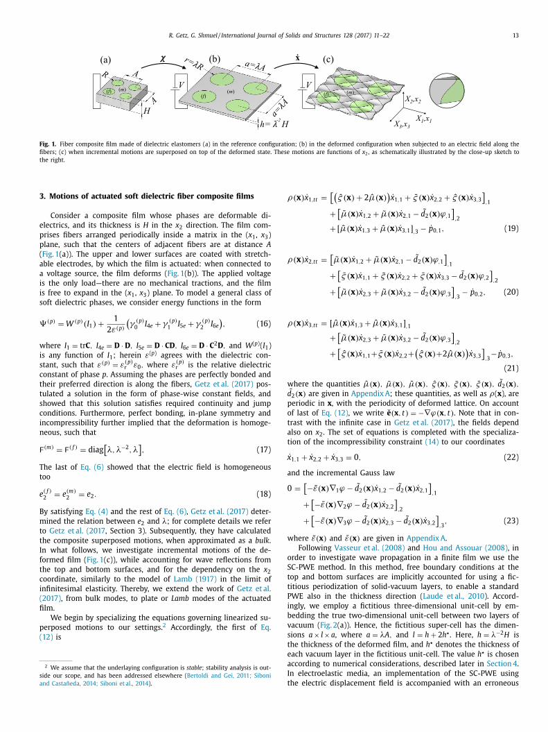
Fig. 1. Fiber composite film made of dielectric elastomers (a) in the reference configuration; (b) in the deformed configuration when subjected to an electric field along the fibers; (c) when incremental motions are superposed on top of the deformed state. These motions are functions of x 2 , as schematically illustrated by the close-up sketch to the right. 3. Motions of actuated soft dielectric fiber composite films
Consider a composite film whose phases are deformable di- electrics, and its thickness is H in the x 2 direction. The film com- prises fibers arranged periodically inside a matrix in the ( x 1 , x 3 ) plane, such that the centers of adjacent fibers are at distance A ( Fig. 1 (a)). The upper and lower surfaces are coated with stretch- able electrodes, by which the film is actuated: when connected to a voltage source, the film deforms ( Fig. 1 (b)). The applied voltage is the only load—there are no mechanical tractions, and the film is free to expand in the ( x 1 , x 3 ) plane. To model a general class of soft dielectric phases, we consider energy functions in the form ' (p) = W (p) ( I 1 ) + 1
2 ε (p) (γ (p) 0 I 4 e + γ (p)
1 I 5 e + γ (p) 2 I 6 e ), (16)
where I 1 = tr C , I 4 e = D · D , I 5 e = D · CD , I 6 e = D · C 2 D , and W ( p ) ( I 1 ) is any function of I 1 ; herein ε( p ) agrees with the dielectric con- stant, such that ε (p) = ε (p)
r ε 0 , where ε (p) r is the relative dielectric
constant of phase p . Assuming the phases are perfectly bonded and their preferred direction is along the fibers, Getz et al. (2017) pos- tulated a solution in the form of phase-wise constant fields, and showed that this solution satisfies required continuity and jump conditions. Furthermore, perfect bonding, in-plane symmetry and incompressibility further implied that the deformation is homoge- neous, such that F (m ) = F ( f ) = diag [λ, λ−2 , λ]
, (17) The last of Eq. (6) showed that the electric field is homogeneous too e ( f )
2 = e (m ) 2 = e 2 . (18)
By satisfying Eq. (4) and the rest of Eq. (6) , Getz et al. (2017) deter- mined the relation between e 2 and λ; for complete details we refer to Getz et al. (2017 , Section 3). Subsequently, they have calculated the composite superposed motions, when approximated as a bulk . In what follows, we investigate incremental motions of the de- formed film ( Fig. 1 (c)), while accounting for wave reflections from the top and bottom surfaces, and for the dependency on the x 2 coordinate, similarly to the model of Lamb (1917) in the limit of infinitesimal elasticity. Thereby, we extend the work of Getz et al. (2017) , from bulk modes, to plate or Lamb modes of the actuated film.
We begin by specializing the equations governing linearized su- perposed motions to our settings. 2 Accordingly, the first of Eq. (12) is
2 We assume that the underlaying configuration is stable ; stability analysis is out- side our scope, and has been addressed elsewhere ( Bertoldi and Gei, 2011; Siboni and Castañeda, 2014; Siboni et al., 2014 ).
ρ( x ) x 1 ,tt = [( ˆ ς ( x ) + 2 µ( x ) ) ˙ x 1 , 1 + ς ( x ) x 2 , 2 + ˆ ς ( x ) x 3 , 3 ], 1 + [µ( x ) x 1 , 2 + ˜ µ( x ) x 2 , 1 − ˜ d 2 ( x ) ϕ , 1 ], 2 + [ µ( x ) x 1 , 3 + ˆ µ( x ) x 3 , 1 ] , 3 − ˙ p 0 , 1 , (19)
ρ( x ) x 2 ,tt = [ ˜ µ( x ) x 1 , 2 + ˜ µ( x ) x 2 , 1 − ˜ d 2 ( x ) ϕ , 1 ], 1 + [ς ( x ) x 1 , 1 + ˜ ς ( x ) x 2 , 2 + ς ( x ) x 3 , 3 − d 2 ( x ) ϕ , 2 ], 2 + [ ˜ µ( x ) x 2 , 3 + ˜ µ( x ) x 3 , 2 − ˜ d 2 ( x ) ϕ , 3 ], 3 − ˙ p 0 , 2 , (20)
ρ( x ) x 3 ,tt = [ µ( x ) x 1 , 3 + ˆ µ( x ) x 3 , 1 ] , 1 + [ ˜ µ( x ) x 2 , 3 + µ( x ) x 3 , 2 − ˜ d 2 ( x ) ϕ , 3 ], 2 + [ ˆ ς ( x ) x 1 , 1 + ς ( x ) x 2 , 2 + ( ˆ ς ( x ) +2 µ( x ) ) ˙ x 3 , 3 ], 3 − ˙ p 0 , 3 ,
(21) where the quantities ˆ µ( x ) , ˜ µ( x ) , µ( x ) , ˆ ς ( x ) , ˜ ς ( x ) , ς ( x ) , ˜ d 2 ( x ) , d 2 ( x ) are given in Appendix A ; these quantities, as well as ρ( x ), are periodic in x , with the periodicity of deformed lattice. On account of last of Eq. (12) , we write e ( x , t ) = −∇ϕ ( x , t ) . Note that in con- trast with the infinite case in Getz et al. (2017) , the fields depend also on x 2 . The set of equations is completed with the specializa- tion of the incompressibility constraint (14) to our coordinates ˙ x 1 , 1 + ˙ x 2 , 2 + ˙ x 3 , 3 = 0 , (22)
and the incremental Gauss law 0 = [− ˜ ε ( x ) ∇ 1 ϕ − ˜ d 2 ( x ) x 1 , 2 − ˜ d 2 ( x ) x 2 , 1 ], 1
+ [−ε ( x ) ∇ 2 ϕ − d 2 ( x ) x 2 , 2 ], 2 + [− ˜ ε ( x ) ∇ 3 ϕ − ˜ d 2 ( x ) x 2 , 3 − ˜ d 2 ( x ) x 3 , 2 ], 3 , (23)
where ˜ ε ( x ) and ε ( x ) are given in Appendix A . Following Vasseur et al. (2008) and Hou and Assouar (2008) , in
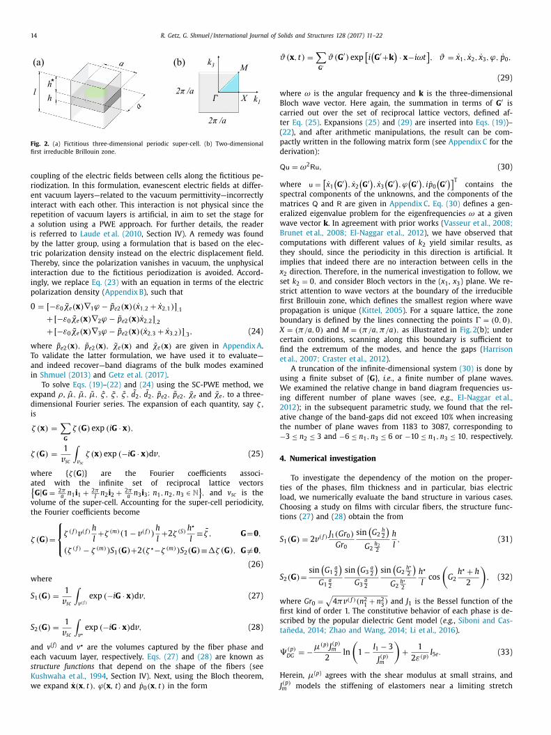
order to investigate wave propagation in a finite film we use the SC-PWE method. In this method, free boundary conditions at the top and bottom surfaces are implicitly accounted for using a fic- titious periodization of solid-vacuum layers, to enable a standard PWE also in the thickness direction ( Laude et al., 2010 ). Accord- ingly, we employ a fictitious three-dimensional unit-cell by em- bedding the true two-dimensional unit-cell between two layers of vacuum ( Fig. 2 (a)). Hence, the fictitious super-cell has the dimen- sions a × l × a , where a = λA, and l = h + 2 h ⋆ . Here, h = λ−2 H is the thickness of the deformed film, and h ⋆ denotes the thickness of each vacuum layer in the fictitious unit-cell. The value h ⋆ is chosen according to numerical considerations, described later in Section 4 . In electroelastic media, an implementation of the SC-PWE using the electric displacement field is accompanied with an erroneous
14 R. Getz, G. Shmuel / International Journal of Solids and Structures 128 (2017) 11–22
Fig. 2. (a) Fictitious three-dimensional periodic super-cell. (b) Two-dimensional first irreducible Brillouin zone. coupling of the electric fields between cells along the fictitious pe- riodization. In this formulation, evanescent electric fields at differ- ent vacuum layers—related to the vacuum permittivity—incorrectly interact with each other. This interaction is not physical since the repetition of vacuum layers is artificial, in aim to set the stage for a solution using a PWE approach. For further details, the reader is referred to Laude et al. (2010 , Section IV). A remedy was found by the latter group, using a formulation that is based on the elec- tric polarization density instead on the electric displacement field. Thereby, since the polarization vanishes in vacuum, the unphysical interaction due to the fictitious periodization is avoided. Accord- ingly, we replace Eq. (23) with an equation in terms of the electric polarization density ( Appendix B ), such that 0 = [ −ε 0 ˜ χe ( x ) ∇ 1 ϕ − ˜ p e 2 ( x ) ( x 1 , 2 + ˙ x 2 , 1 ) ] , 1
+ [ −ε 0 χe ( x ) ∇ 2 ϕ − p e 2 ( x ) x 2 , 2 ] , 2 + [ −ε 0 ˜ χe ( x ) ∇ 3 ϕ − ˜ p e 2 ( x ) ( x 2 , 3 + ˙ x 3 , 2 ) ] , 3 , (24)
where ˜ p e 2 ( x ) , p e 2 ( x ) , ˜ χe ( x ) and χe ( x ) are given in Appendix A . To validate the latter formulation, we have used it to evaluate—and indeed recover—band diagrams of the bulk modes examined in Shmuel (2013) and Getz et al. (2017) .
To solve Eqs. (19) –(22) and (24) using the SC-PWE method, we expand ρ , ˆ µ, ˜ µ, µ, ˆ ς , ˜ ς , ς , ˜ d 2 , d 2 , ˜ p e 2 , p e 2 , ˜ χe and χe , to a three- dimensional Fourier series. The expansion of each quantity, say ζ , is ζ ( x ) = ∑
G ζ ( G ) exp ( i G · x ) , ζ ( G ) = 1
v sc ∫
v sc ζ ( x ) exp ( −i G · x ) d v , (25) where { ζ ( G )} are the Fourier coefficients associ- ated with the infinite set of reciprocal lattice vectors {
G | G = 2 πa n 1 i 1 + 2 π
l n 2 i 2 + 2 πa n 3 i 3 ; n 1 , n 2 , n 3 ∈ N }, and v sc is the
volume of the super-cell. Accounting for the super-cell periodicity, the Fourier coefficients become ζ (G ) =
⎧ ⎨ ⎩ ζ
( f ) v ( f ) h l +ζ (m ) (1 − v ( f ) ) h
l +2 ζ (S) h ⋆ l ≡ ζ , G = 0 ,
(ζ ( f ) − ζ (m ) ) S 1 (G ) + 2(ζ ⋆ −ζ (m ) ) S 2 (G ) ≡1ζ (G ) , G = 0 , (26)
where S 1 ( G ) = 1
v sc ∫
v ( f ) exp ( −i G · x ) d v , (27) S 2 ( G ) = 1
v sc ∫
v ⋆ exp ( −i G · x ) d v , (28) and v ( f ) and v ⋆ are the volumes captured by the fiber phase and each vacuum layer, respectively. Eqs. (27) and (28) are known as structure functions that depend on the shape of the fibers (see Kushwaha et al., 1994 , Section IV). Next, using the Bloch theorem, we expand ˙ x ( x , t ) , ϕ( x , t ) and ˙ p 0 ( x , t ) in the form
ϑ (x , t) = ∑ G ′ ϑ ( G ′ ) exp [i (G ′ +k ) · x −iωt ], ϑ = ˙ x 1 , ˙ x 2 , ˙ x 3 , ϕ, ˙ p 0 ,
(29) where ω is the angular frequency and k is the three-dimensional Bloch wave vector. Here again, the summation in terms of G ′ is carried out over the set of reciprocal lattice vectors, defined af- ter Eq. (25) . Expansions (25) and (29) are inserted into Eqs. (19) )–( 22 ), and after arithmetic manipulations, the result can be com- pactly written in the following matrix form (see Appendix C for the derivation): Qu = ω 2 Ru , (30) where u = [ ˙ x 1 (G ′ ), ˙ x 2 (G ′ ), ˙ x 3 (G ′ ), ϕ (G ′ ), i p 0 (G ′ )]T
contains the spectral components of the unknowns, and the components of the matrices Q and R are given in Appendix C . Eq. (30) defines a gen- eralized eigenvalue problem for the eigenfrequencies ω at a given wave vector k . In agreement with prior works ( Vasseur et al., 2008; Brunet et al., 2008; El-Naggar et al., 2012 ), we have observed that computations with different values of k 2 yield similar results, as they should, since the periodicity in this direction is artificial. It implies that indeed there are no interaction between cells in the x 2 direction. Therefore, in the numerical investigation to follow, we set k 2 = 0 , and consider Bloch vectors in the ( x 1 , x 3 ) plane. We re- strict attention to wave vectors at the boundary of the irreducible first Brillouin zone, which defines the smallest region where wave propagation is unique ( Kittel, 2005 ). For a square lattice, the zone boundary is defined by the lines connecting the points 4 = ( 0 , 0 ) , X = ( π/a, 0 ) and M = ( π/a, π/a ) , as illustrated in Fig. 2 (b); under certain conditions, scanning along this boundary is sufficient to find the extremum of the modes, and hence the gaps ( Harrison et al., 2007; Craster et al., 2012 ).
A truncation of the infinite-dimensional system (30) is done by using a finite subset of { G }, i.e. , a finite number of plane waves. We examined the relative change in band diagram frequencies us- ing different number of plane waves (see, e.g. , El-Naggar et al., 2012 ); in the subsequent parametric study, we found that the rel- ative change of the band-gaps did not exceed 10% when increasing the number of plane waves from 1183 to 3087, corresponding to −3 ≤ n 2 ≤ 3 and −6 ≤ n 1 , n 3 ≤ 6 or −10 ≤ n 1 , n 3 ≤ 10 , respectively. 4. Numerical investigation
To investigate the dependency of the motion on the proper- ties of the phases, film thickness and in particular, bias electric load, we numerically evaluate the band structure in various cases. Choosing a study on films with circular fibers, the structure func- tions ( 27 ) and ( 28 ) obtain the from S 1 ( G ) = 2 v ( f ) J 1 ( Gr 0 )
Gr 0 sin (G 2 h 2 )G 2 h 2 2
h l , (31)
S 2 ( G ) = sin (G 1 a 2 )G 1 a 2
sin (G 3 a 2 )G 3 a 2
sin (G 2 h ⋆ 2 )G 2 h ⋆ 2
h ⋆ l cos (G 2 h ⋆ + h
2 )
, (32) where Gr 0 = √
4 πv ( f ) (n 2 1 + n 2 3 ) and J 1 is the Bessel function of the first kind of order 1. The constitutive behavior of each phase is de- scribed by the popular dielectric Gent model ( e.g. , Siboni and Cas- tañeda, 2014; Zhao and Wang, 2014; Li et al., 2016 ). ' (p)
DG = −µ(p) J (p) m
2 ln (1 − I 1 − 3 J (p) m
)+ 1
2 ε (p) I 5 e . (33) Herein, µ( p ) agrees with the shear modulus at small strains, and J ( p ) m models the stiffening of elastomers near a limiting stretch
R. Getz, G. Shmuel / International Journal of Solids and Structures 128 (2017) 11–22 15
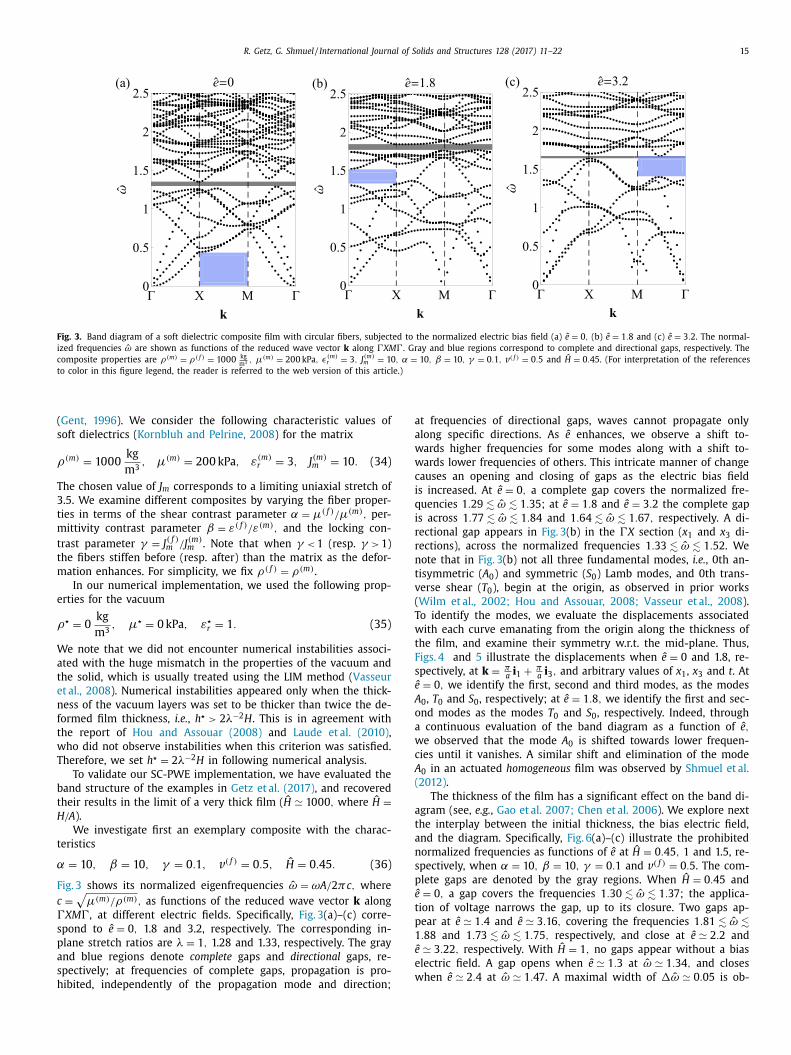
Fig. 3. Band diagram of a soft dielectric composite film with circular fibers, subjected to the normalized electric bias field (a) ˆ e = 0 , (b) ˆ e = 1 . 8 and (c) ˆ e = 3 . 2 . The normal- ized frequencies ˆ ω are shown as functions of the reduced wave vector k along 4XM 4. Gray and blue regions correspond to complete and directional gaps, respectively. The composite properties are ρ(m ) = ρ( f ) = 10 0 0 kg
m 3 , µ(m ) = 20 0 kPa , ϵ(m ) r = 3 , J (m )
m = 10 , α = 10 , β = 10 , γ = 0 . 1 , v ( f ) = 0 . 5 and ˆ H = 0 . 45 . (For interpretation of the references to color in this figure legend, the reader is referred to the web version of this article.) ( Gent, 1996 ). We consider the following characteristic values of soft dielectrics ( Kornbluh and Pelrine, 2008 ) for the matrix ρ(m ) = 10 0 0 kg
m 3 , µ(m ) = 20 0 kPa , ε (m ) r = 3 , J (m )
m = 10 . (34) The chosen value of J m corresponds to a limiting uniaxial stretch of 3.5. We examine different composites by varying the fiber proper- ties in terms of the shear contrast parameter α = µ( f ) /µ(m ) , per- mittivity contrast parameter β = ε ( f ) /ε (m ) , and the locking con- trast parameter γ = J ( f )
m /J (m ) m . Note that when γ < 1 (resp. γ > 1)
the fibers stiffen before (resp. after) than the matrix as the defor- mation enhances. For simplicity, we fix ρ( f ) = ρ( m ) .
In our numerical implementation, we used the following prop- erties for the vacuum ρ⋆ = 0 kg
m 3 , µ⋆ = 0 kPa , ε ⋆ r = 1 . (35) We note that we did not encounter numerical instabilities associ- ated with the huge mismatch in the properties of the vacuum and the solid, which is usually treated using the LIM method ( Vasseur et al., 2008 ). Numerical instabilities appeared only when the thick- ness of the vacuum layers was set to be thicker than twice the de- formed film thickness, i.e. , h ⋆ > 2 λ−2 H. This is in agreement with the report of Hou and Assouar (2008) and Laude et al. (2010) , who did not observe instabilities when this criterion was satisfied. Therefore, we set h ⋆ = 2 λ−2 H in following numerical analysis.
To validate our SC-PWE implementation, we have evaluated the band structure of the examples in Getz et al. (2017) , and recovered their results in the limit of a very thick film ( H ≃ 10 0 0 , where ˆ H = H/A ).
We investigate first an exemplary composite with the charac- teristics α = 10 , β = 10 , γ = 0 . 1 , v ( f ) = 0 . 5 , ˆ H = 0 . 45 . (36) Fig. 3 shows its normalized eigenfrequencies ˆ ω = ωA/ 2 πc, where c = √
µ( m ) /ρ( m ) , as functions of the reduced wave vector k along 4XM 4, at different electric fields. Specifically, Fig. 3 (a)–(c) corre- spond to ˆ e = 0 , 1.8 and 3.2, respectively. The corresponding in- plane stretch ratios are λ = 1 , 1.28 and 1.33, respectively. The gray and blue regions denote complete gaps and directional gaps, re- spectively; at frequencies of complete gaps, propagation is pro- hibited, independently of the propagation mode and direction;
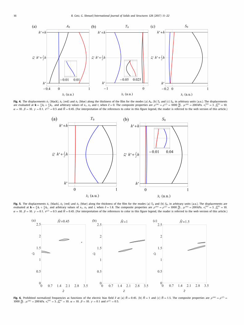
at frequencies of directional gaps, waves cannot propagate only along specific directions. As ˆ e enhances, we observe a shift to- wards higher frequencies for some modes along with a shift to- wards lower frequencies of others. This intricate manner of change causes an opening and closing of gaps as the electric bias field is increased. At ˆ e = 0 , a complete gap covers the normalized fre- quencies 1 . 29 ! ˆ ω ! 1 . 35 ; at ˆ e = 1 . 8 and ˆ e = 3 . 2 the complete gap is across 1 . 77 ! ˆ ω ! 1 . 84 and 1 . 64 ! ˆ ω ! 1 . 67 , respectively. A di- rectional gap appears in Fig. 3 (b) in the 4X section ( x 1 and x 3 di- rections), across the normalized frequencies 1 . 33 ! ˆ ω ! 1 . 52 . We note that in Fig. 3 (b) not all three fundamental modes, i.e. , 0 th an- tisymmetric ( A 0 ) and symmetric ( S 0 ) Lamb modes, and 0 th trans- verse shear ( T 0 ), begin at the origin, as observed in prior works ( Wilm et al., 2002; Hou and Assouar, 2008; Vasseur et al., 2008 ). To identify the modes, we evaluate the displacements associated with each curve emanating from the origin along the thickness of the film, and examine their symmetry w.r.t. the mid-plane. Thus, Figs. 4 and 5 illustrate the displacements when ˆ e = 0 and 1.8, re- spectively, at k = πa i 1 + πa i 3 , and arbitrary values of x 1 , x 3 and t . At ˆ e = 0 , we identify the first, second and third modes, as the modes A 0 , T 0 and S 0 , respectively; at ˆ e = 1 . 8 , we identify the first and sec- ond modes as the modes T 0 and S 0 , respectively. Indeed, through a continuous evaluation of the band diagram as a function of ˆ e , we observed that the mode A 0 is shifted towards lower frequen- cies until it vanishes. A similar shift and elimination of the mode A 0 in an actuated homogeneous film was observed by Shmuel et al. (2012) .
The thickness of the film has a significant effect on the band di- agram (see, e.g. , Gao et al. 2007; Chen et al. 2006 ). We explore next the interplay between the initial thickness, the bias electric field, and the diagram. Specifically, Fig. 6 (a)–(c) illustrate the prohibited normalized frequencies as functions of ˆ e at ˆ H = 0 . 45 , 1 and 1.5, re- spectively, when α = 10 , β = 10 , γ = 0 . 1 and v ( f ) = 0 . 5 . The com- plete gaps are denoted by the gray regions. When ˆ H = 0 . 45 and ˆ e = 0 , a gap covers the frequencies 1 . 30 ! ˆ ω ! 1 . 37 ; the applica- tion of voltage narrows the gap, up to its closure. Two gaps ap- pear at ˆ e ≃ 1 . 4 and ˆ e ≃ 3 . 16 , covering the frequencies 1 . 81 ! ˆ ω ! 1 . 88 and 1 . 73 ! ˆ ω ! 1 . 75 , respectively, and close at ˆ e ≃ 2 . 2 and ˆ e ≃ 3 . 22 , respectively. With ˆ H = 1 , no gaps appear without a bias electric field. A gap opens when ˆ e ≃ 1 . 3 at ˆ ω ≃ 1 . 34 , and closes when ˆ e ≃ 2 . 4 at ˆ ω ≃ 1 . 47 . A maximal width of 1 ˆ ω ≃ 0 . 05 is ob-
16 R. Getz, G. Shmuel / International Journal of Solids and Structures 128 (2017) 11–22
Fig. 4. The displacements ˙ x 1 (black), ˙ x 2 (red) and ˙ x 3 (blue) along the thickness of the film for the modes (a) A 0 , (b) T 0 and (c) S 0 , in arbitrary units (a.u.). The displacements are evaluated at k = πa i 1 + πa i 3 , and arbitrary values of x 1 , x 3 and t , when ˆ e = 0 . The composite properties are ρ(m ) = ρ( f ) = 10 0 0 kg
m 3 , µ(m ) = 20 0 kPa , ϵ(m ) r = 3 , J (m )
m = 10 , α = 10 , β = 10 , γ = 0 . 1 , v ( f ) = 0 . 5 and ˆ H = 0 . 45 . (For interpretation of the references to color in this figure legend, the reader is referred to the web version of this article.)
Fig. 5. The displacements ˙ x 1 (black), ˙ x 2 (red) and ˙ x 3 (blue) along the thickness of the film for the modes (a) T 0 and (b) S 0 , in arbitrary units (a.u.). The displacements are evaluated at k = πa i 1 + πa i 3 , and arbitrary values of x 1 , x 3 and t , when ˆ e = 1 . 8 . The composite properties are ρ(m ) = ρ( f ) = 10 0 0 kg
m 3 , µ(m ) = 20 0 kPa , ϵ(m ) r = 3 , J (m )
m = 10 , α = 10 , β = 10 , γ = 0 . 1 , v ( f ) = 0 . 5 and ˆ H = 0 . 45 . (For interpretation of the references to color in this figure legend, the reader is referred to the web version of this article.)
Fig. 6. Prohibited normalized frequencies as functions of the electric bias field ˆ e at (a) ˆ H = 0 . 45 , (b) ˆ H = 1 and (c) ˆ H = 1 . 5 . The composite properties are ρ(m ) = ρ( f ) = 10 0 0 kg
m 3 , µ(m ) = 20 0 kPa , ϵ(m ) r = 3 , J (m )
m = 10 , α = 10 , β = 10 , γ = 0 . 1 and v ( f ) = 0 . 5 .
R. Getz, G. Shmuel / International Journal of Solids and Structures 128 (2017) 11–22 17
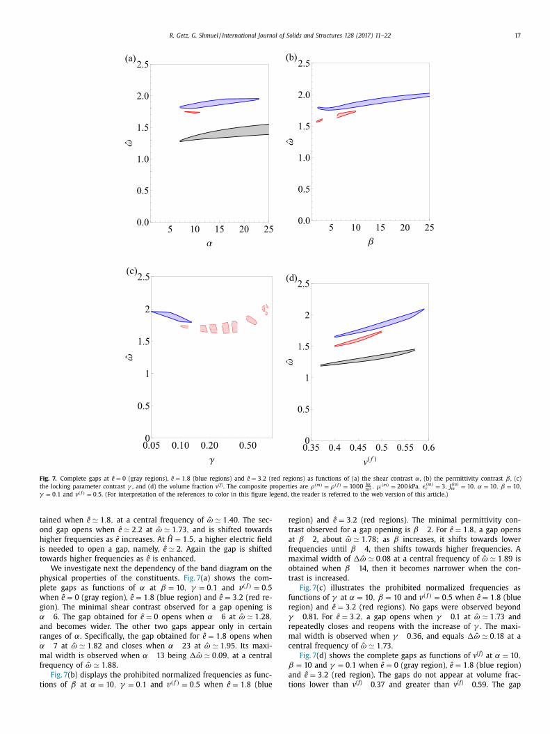
Fig. 7. Complete gaps at ˆ e = 0 (gray regions), ˆ e = 1 . 8 (blue regions) and ˆ e = 3 . 2 (red regions) as functions of (a) the shear contrast α, (b) the permittivity contrast β , (c) the locking parameter contrast γ , and (d) the volume fraction v ( f ) . The composite properties are ρ(m ) = ρ( f ) = 10 0 0 kg
m 3 , µ(m ) = 20 0 kPa , ϵ(m ) r = 3 , J (m )
m = 10 , α = 10 , β = 10 , γ = 0 . 1 and v ( f ) = 0 . 5 . (For interpretation of the references to color in this figure legend, the reader is referred to the web version of this article.) tained when ˆ e ≃ 1 . 8 , at a central frequency of ˆ ω ≃ 1 . 40 . The sec- ond gap opens when ˆ e ≃ 2 . 2 at ˆ ω ≃ 1 . 73 , and is shifted towards higher frequencies as ˆ e increases. At ˆ H = 1 . 5 , a higher electric field is needed to open a gap, namely, ˆ e ≃ 2 . Again the gap is shifted towards higher frequencies as ˆ e is enhanced.
We investigate next the dependency of the band diagram on the physical properties of the constituents. Fig. 7 (a) shows the com- plete gaps as functions of α at β = 10 , γ = 0 . 1 and v ( f ) = 0 . 5 when ˆ e = 0 (gray region), ˆ e = 1 . 8 (blue region) and ˆ e = 3 . 2 (red re- gion). The minimal shear contrast observed for a gap opening is α ! 6. The gap obtained for ˆ e = 0 opens when α ! 6 at ˆ ω ≃ 1 . 28 , and becomes wider. The other two gaps appear only in certain ranges of α. Specifically, the gap obtained for ˆ e = 1 . 8 opens when α ! 7 at ˆ ω ≃ 1 . 82 and closes when α ! 23 at ˆ ω ≃ 1 . 95 . Its maxi- mal width is observed when α ! 13 being 1 ˆ ω ≃ 0 . 09 , at a central frequency of ˆ ω ≃ 1 . 88 .
Fig. 7 (b) displays the prohibited normalized frequencies as func- tions of β at α = 10 , γ = 0 . 1 and v ( f ) = 0 . 5 when ˆ e = 1 . 8 (blue
region) and ˆ e = 3 . 2 (red regions). The minimal permittivity con- trast observed for a gap opening is β ! 2. For ˆ e = 1 . 8 , a gap opens at β ! 2, about ˆ ω ≃ 1 . 78 ; as β increases, it shifts towards lower frequencies until β ! 4, then shifts towards higher frequencies. A maximal width of 1 ˆ ω ≃ 0 . 08 at a central frequency of ˆ ω ≃ 1 . 89 is obtained when β ! 14, then it becomes narrower when the con- trast is increased.
Fig. 7 (c) illustrates the prohibited normalized frequencies as functions of γ at α = 10 , β = 10 and v ( f ) = 0 . 5 when ˆ e = 1 . 8 (blue region) and ˆ e = 3 . 2 (red regions). No gaps were observed beyond γ ! 0.81. For ˆ e = 3 . 2 , a gap opens when γ ! 0.1 at ˆ ω ≃ 1 . 73 and repeatedly closes and reopens with the increase of γ . The maxi- mal width is observed when γ ! 0.36, and equals 1 ˆ ω ≃ 0 . 18 at a central frequency of ˆ ω ≃ 1 . 73 .
Fig. 7 (d) shows the complete gaps as functions of v ( f ) at α = 10 , β = 10 and γ = 0 . 1 when ˆ e = 0 (gray region), ˆ e = 1 . 8 (blue region) and ˆ e = 3 . 2 (red region). The gaps do not appear at volume frac- tions lower than v ( f ) ! 0.37 and greater than v ( f ) ! 0.59. The gap
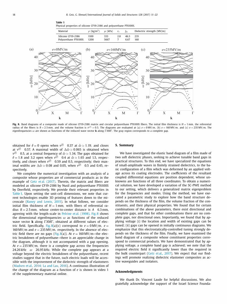
18 R. Getz, G. Shmuel / International Journal of Solids and Structures 128 (2017) 11–22 Table 1 Physical properties of silicone CF19-2186 and polyurethane PT6100S.
Material ρ (kg/m 3 ) µ (kPa) εr J m Dielectric strength (MV/m) Silicone CF19-2186 1100 333 2.8 46.3 235 Polyurethane PT6100S 1200 5667 7 6.67 160
Fig. 8. Band diagrams of a composite made of silicone CF19-2186 matrix and circular polyurethane PT6100S fibers. The initial film thickness is H = 1 mm , the referential radius of the fibers is R = 2 . 5 mm , and the volume fraction is v ( f ) = 0 . 5 . The diagrams are evaluated at (a) e = 0 MV / m , (b) e = 160 MV / m , and (c) e = 235 MV / m . The eigenfrequencies ω are shown as functions of the reduced wave vector k along 4XM 4. The gray region corresponds to a complete gap. obtained for ˆ e = 0 opens when v ( f ) ! 0.37 at ˆ ω ≃ 1 . 19 , and closes at v ( f ) ! 0.57. A maximal width of 1 ˆ ω ≃ 0 . 065 is obtained when v ( f ) ! 0.5, at a central frequency of ˆ ω ≃ 1 . 34 . The gaps obtained for ˆ e = 1 . 8 and 3.2 open when v ( f ) ! 0.4 at ˆ ω ≃ 1 . 65 and 1.5, respec- tively, and closes when v ( f ) ! 0.59 and 0.5, respectively; their max- imal widths are 1 ˆ ω ≃ 0 . 08 and 0.05, when v ( f ) ! 0.5 and 0.45, re- spectively.
We complete the numerical investigation with an analysis of a composite whose properties are of commercial products as in the example of Getz et al. (2017) . Therein, the matrix and fibers are modeled as silicone CF19-2186 by Nusil and polyurethane PT6100S by Deerfield, respectively. We provide their relevant properties in Table 1 . Upon setting the unit-cell dimensions, we note that cur- rent technologies enable 3D printing of features down to the mi- croscale ( Raney and Lewis, 2015 ). In what follows, we consider initial film thickness of H = 1 mm , with fibers of referential ra- dius R = 2 . 5 mm , whose center-to-center distance is A ! 6.3 mm, agreeing with the length-scale in Pelrine et al. (1998) . Fig. 8 shows the dimensional eigenfrequencies ω as functions of the reduced wave vector k along 4XM 4, obtained at different values of elec- tric field. Specifically, Fig. 8 (a)(c) correspond to e = 0 MV / m , e = 160 MV / m and e = 235 MV / m , respectively. In the absence of elec- tric field there are no gaps ( Fig. 8 (a)). At e = 160 MV / m —the elec- tric breakdown of polyurethane—there is an appreciable change in the diagram, although it is not accompanied with a gap opening. At e = 235 MV / m , there is a complete gap across the frequencies 24.26 kHz " ω " 26.95 kHz. While the complete gap appears at a voltage beyond the electric breakdown of the polyurethane, recent studies suggest that in the future, such electric loads will be acces- sible with the improvement of the dielectric strength of elastomers ( Madsen et al., 2014; La and Lau, 2016 ). A continuous illustration of the change of the diagram as a function of e is shown in video 1 of the supplementary material online.
5. Summary We have investigated the elastic band diagram of a film made of
two soft dielectric phases, seeking to achieve tunable band gaps in practical structures. To this end, we have specialized the equations of small-amplitude waves in finitely strained dielectrics, to the ba- sic configuration of a film which was deformed by an applied volt- age across its coating electrodes. The coefficients of the resultant coupled differential equations are position dependent, whose un- knowns are functions of all three coordinates. To obtain a numeri- cal solution, we have developed a variation of the SC-PWE method to our setting, which delivers a generalized matrix eigenproblem for the frequencies and modes. Using the method, we have exe- cuted a parametric study to explore how the band structure de- pends on the thickness of the film, the volume fraction of the con- stituents, and their physical properties. We found that for certain combinations of the above parameters, there exist directional and complete gaps, and that for other combinations there are no com- plete gaps, nor directional ones. Importantly, we found that by ap- plying voltage (i) the location and width of existing gaps can be tuned; (ii) gaps can be opened in initially continuous diagrams. We emphasize that this electrostatically-controlled tuning strongly de- pends on the thickness of the film. Finally, we have examined the band diagram of a composite whose constituent properties corre- spond to commercial products. We have demonstrated that by ap- plying voltage, a complete band gap is achieved; we note that the required electric field it significantly lower than the required in the bulk counterpart ( Getz et al., 2017 ). We expect that our find- ings will promote realizing dielectric elastomer composites as ac- tive waveguides and isolators. Acknowledgments
We thank Dr. Vincent Laude for helpful discussions. We also gratefully acknowledge the support of the Israel Science Founda-
R. Getz, G. Shmuel / International Journal of Solids and Structures 128 (2017) 11–22 19 tion, founded by the Israel Academy of Sciences and Humanities (Grant No. 1912/15 ) and the United States-Israel Binational Science Foundation support (Grant No. 2014358). Appendix A
The quantities ˆ µ( x ) , ˜ µ( x ) , µ( x ) , ˆ ς ( x ) , ˜ ς ( x ) , ς ( x ) , ˜ d 2 ( x ) , d 2 ( x ) , ˜ ε ( x ) , ε ( x ) , ˜ p e 2 ( x ) , p e 2 ( x ) , ˜ χe ( x ) and χe ( x ) are ˆ µ(x ) = µ( x ) λ2 , (A.1) ˜ µ(x ) =
{ λ8 γ ( x ) γ2 ( x ) − [(
λ6 + 1 )γ2 ( x ) + λ4 γ1 ( x ) ]2 ˆ γ 2 ( x ) γ ( x )
}
× λ2 ε ( x ) e 2 2 + ˆ µ( x ) , (A.2) µ(x ) = {
λ2 γ ( x ) [(λ6 +2 )γ2 ( x ) + λ4 γ1 ( x ) ] −[(
λ6 + 1 )γ2 ( x ) + λ4 γ1 ( x ) ]2 ˆ γ 2 ( x ) γ ( x )
} × λ2 ε ( x ) e 2 2 + µ( x ) λ−4 , (A.3)
ˆ ς (x ) = ς ( x ) λ4 , (A.4) ˜ ς (x ) =
[ ˆ γ ( x ) (λ4 γ1 ( x ) + 6 γ2 ( x ) ) −
(2 λ4 γ1 ( x ) + 4 γ2 ( x ) )2
ˆ γ ( p ) 3 ]
× λ4 ε ( x ) e 2 2 + ς ( x ) λ−8 + µ( x ) (λ−4 + λ2 ), (A.5) ς (x ) = ς ( x ) λ−2 , (A.6) ˜ d 2 (x ) =
[ γ2 ( x ) (λ6 + 1 ) + γ1 ( x ) λ4
ˆ γ ( x ) γ ( x ) ] λ2 ε(x ) e 2 , (A.7)
d 2 (x ) = [2 λ4 γ1 ( x ) + 4 γ2 ( x ) ˆ γ 2 ( x )
]λ4 ε(x ) e 2 , (A.8)
˜ ε (x ) = λ2 γ ( x ) ε(x ) , (A.9)
ε (x ) = λ4 ˆ γ ( x ) ε(x ) , (A.10)
˜ p e 2 (x ) = { [
γ2 ( x ) (λ6 + 1 ) + γ1 ( x ) λ4 ˆ γ ( x ) γ ( x )
] λ2 ε(x )
ε 0 − 1 }
ε 0 e 2 , (A.11)
p e 2 (x ) = {[2 λ4 γ1 ( x ) + 4 γ2 ( x )
ˆ γ 2 ( x ) ]λ4 ε(x )
ε 0 − 1 }ε 0 e 2 , (A.12) ˜ χe (x ) = λ2
γ ( x ) ε(x ) ε 0 − 1 , (A.13)
χe (x ) = λ4 ˆ γ ( x ) ε(x )
ε 0 − 1 , (A.14) where ς (p) = 4 ∂ 2 W (p)
1 ∂ 2 I 1 , µ(p) = 2 ∂W (p)
1 ∂ I 1 , ˆ γ ( x ) = λ8 γ0 ( x ) + λ4 γ1 ( x ) +
γ2 ( x ) and γ ( x ) = γ0 ( x ) + λ2 γ1 ( x ) + λ4 γ2 ( x ) .
When specialized to Eq. (33) , we have ˆ µ(x ) = µ( x ) λ2
1 − 2 λ2 + λ−4 −3 J m ( x ) , (A.15)
˜ µ(x ) = ˆ µ(x ) − ε(x ) e 2 2 , (A.16) µ(x ) = µ( x ) λ−4
1 − 2 λ2 + λ−4 −3 J m ( x ) , (A.17)
ˆ ς (x ) = 2 µ( x ) λ4 J m ( x ) (1 − 2 λ2 + λ−4 −3
J m ( x ) )2 , (A.18) ˜ ς (x ) = 2 µ( x ) λ−8
J m ( x ) (1 − 2 λ2 + λ−4 −3 J m ( x ) )2 + ˆ µ( x ) + µ( x ) − 3 ε(x ) e 2 2 , (A.19)
ς (x ) = 2 µ( x ) λ−2 J m ( x ) (1 − 2 λ2 + λ−4 −3
J m ( x ) )2 , (A.20) ˜ d (x ) = ε(x ) e 2 = d 2 ( x ) , (A.21)
d (x ) = 2 ε(x ) e 2 = 2 d 2 ( x ) , (A.22) ˜ ε (x ) = ε(x ) , (A.23) ε (x ) = ε(x ) , (A.24) ˜ p (x ) = (ε(x )
ε 0 − 1 )ε 0 e 2 = p e 2 ( x ) , (A.25) p (x ) = 2 (ε(x )
ε 0 − 1 )ε 0 e ( p ) 2 = 2 p e 2 ( x ) , (A.26) ˜ χ (x ) = ε(x )
ε 0 − 1 , (A.27) χe (x ) = ε(x )
ε 0 − 1 . (A.28) Appendix B
We derive the linear approximation of the electric polarization density. This is done using an expansion of Eq. (9) as a Taylor series about the static current configuration, such that ˙ P e = ˙ D − ε 0 ˙ J C −1 E − ε 0 J C −1 E − ε 0 JC −1 E
= ˙ D − ε 0 JC −1 E + ε 0 F −1 ( ˙ F F −1 + F −T F T − JF −T · ˙ F )F −T E , (B.1) where ˙ J = JF −T : ˙ F and ˙ C −1 = −F −1 ( ˙ F F −1 + F −T F T )F −T . Pushing- forward the linear approximation provides p e = J −1 F P e
= J −1 F D − ε 0 F −T E + ε 0 ( ˙ F F −1 + F −T F T )F −T E − ε 0 (F −T · ˙ F )F −T E = d − ε 0 e + ε 0 (h + h T − tr h )e , (B.2)
where ˙ F = hF . In view of the second of Eq. (13) , we can write p e in terms of d , such that p e = (I − ε 0 A −1 )d − ε 0 B T h + ε 0 (h + h T − tr h )e . (B.3)
20 R. Getz, G. Shmuel / International Journal of Solids and Structures 128 (2017) 11–22 When considering an incompressible homogenous material
with an energy density function of the form ' = W elas ( I 1 , I 2 ) + W 5 ( I 5 e ) , (B.4) the constitutive tensors A and B become A i j = 1
ε δi j , (B.5) B i jk = ε (δ jk d i + δik d j ), (B.6) where ε = (2 ∂W 5
∂ I 5 e ) −1 and e = ε d . Note that W elas ( I 1 , I 2 ) is a possibly nonlinear function of I 1 and I 2 = 1
2 [( tr C ) 2 − tr (C 2 )] , where W 5 ( I 5 e ) depends linearly on I 5 e . Applying Eqs. (A.5) and (A.6) to Eq. (A.3) , while considering incompressibility, yields p e = [ 1 − ε 0
ε ]
d . (B.7) Thereby, the divergence of p e becomes ∇ · p e = [ 1 − ε 0
ε ] ∇ · d = 0 , (B.8)
where the last transition relies on Gauss law for d given in the second of Eq. (12) . The divergence of the electric polarization density equals to the minus of volumetric bound charge density. Hence, the incremental volumetric bound charge density vanishes in an incompressible homogeneous dielectric media with an en- ergy function of the form (A.4) . Eq. (24) is obtained when special- izing the constitutive law (16) to a case in which γ (p)
0 = γ (p) 2 = 0
and γ (p) 1 = 1 .
Appendix C Insertion of expansions (25) and (29) into Eqs. (19) –(22) pro-
vides {
∑ G , G ′ [ x 1 ( G ′ )[( ς (G ) + 2 µ(G ))(G ′ + k ) 1 (G + G ′ + k ) 1 + µ(G )(G ′ + k ) 2 (G + G ′ + k ) 2 + ˆ µ(G )(G ′ + k ) 3 (G + G ′ + k ) 3 − ω 2 ρ(G )] + ˙ x 2 ( G ′ )[ ς (G )(G ′ + k ) 2 (G + G ′ + k ) 1 + ˜ µ(G )(G ′ + k ) 1 (G + G ′ + k ) 2 ] + ˙ x 3 ( G ′ )[ ς (G )(G ′ + k ) 3 × (G + G ′ + k ) 1 + ˆ µ(G )(G ′ + k ) 1 (G + G ′ + k ) 3 ] − ϕ(G ′ ) d 2 (G )(G ′ + k ) 1 (G + G ′ + k ) 2 ] exp (i (G + G ′ ) · x ) + ∑
G ′ i ˙ p 0 (G ′ )(G ′ + k ) 1 exp (i G ′ · x ) } exp (i k · x − iωt) = 0 , (C.1)
{∑ G , G ′ [ x 1 ( G ′ )[ µ(G )(G ′ + k ) 2 (G + G ′ + k ) 1 + ς (G )(G ′ + k ) 1 × (G + G ′ + k ) 2 ] + ˙ x 2 ( G ′ )[ µ(G )(G ′ + k ) 1 (G + G ′ + k ) 1 + ˜ ς (G )(G ′ + k ) 2 (G + G ′ + k ) 2 + ˜ µ(G )(G ′ + k ) 3 (G + G ′ + k ) 3 − ω 2 ρ(G )] + ˙ x 3 ( G ′ )[ ς (G )(G ′ + k ) 3 (G + G ′ + k ) 2 + ˜ µ(G ) × (G ′ + k ) 2 (G + G ′ + k ) 3 ] − ϕ(G ′ )[ d 2 (G )(G ′ + k ) 1 (G + G ′ +k ) 1 + d 2 (G )(G ′ + k ) 2 (G + G ′ + k ) 2 + ˜ d 2 (G )(G ′ + k ) 3 (G + G ′ + k ) 3 ]] exp (i (G + G ′ ) · x ) + ∑
G ′ i ˙ p 0 (G ′ )(G ′ + k ) 2 exp (i G ′ · x ) }exp (i k · x − iωt) = 0 , (C.2)
{∑ G , G ′ [ x 1 ( G ′ )[ µ(G )(G ′ + k ) 3 (G + G ′ + k ) 1 + ˆ ς (G )(G ′ + k ) 1 × (G + G ′ + k ) 3 ] + ˙ x 2 ( G ′ )[ µ(G )(G ′ + k ) 3 (G + G ′ + k ) 2 + ς (G )(G ′ + k ) 2 (G + G ′ + k ) 3 ] + ˙ x 3 ( G ′ )[ µ(G )(G ′ + k ) 1 × (G + G ′ + k ) 1 + µ(G )(G ′ + k ) 2 (G + G ′ + k ) 2 + ( ς (G ) + 2 µ(G ))(G ′ + k ) 3 (G + G ′ + k ) 3 − ω 2 ρ(G )] − ϕ(G ′ ) d 2 (G )(G ′ + k ) 3 (G + G ′ + k ) 2 ] exp (i (G + G ′ ) · x ) + ∑
G ′ i ˙ p 0 (G ′ )(G ′ + k ) 3 exp (i G ′ · x ) } exp (i k · x − iωt) = 0 , (C.3)
{∑
G ′ [ x 1 ( G ′ )(G ′ + k ) 1 + ˙ x 2 ( G ′ )(G ′ + k ) 2 + ˙ x 3 ( G ′ )(G ′ + k ) 3 ] exp (G ′ · x ) }i exp (i k · x − iωt) = 0 , (C.4)
{∑ G , G ′ [ − ˙ x 1 ( G ′ ) p e 2 (G )(G ′ + k ) 2 (G + G ′ + k ) 1 − ˙ x 3 ( G ′ ) p e 2 (G ) × (G ′ + k ) 2 (G + G ′ + k ) 3 − ˙ x 2 ( G ′ )[ p e 2 (G )(G ′ + k ) 1 × (G + G ′ + k ) 1 + p e 2 (G )(G ′ + k ) 2 (G + G ′ + k ) 2 + ˜ p e 2 (G )(G ′ + k ) 3 (G + G ′ + k ) 3 ] − ϕ(G ′ ) ε 0 [ χe (G )(G ′ + k ) 1 (G + G ′ + k ) 1 + χe (G )(G ′ + k ) 2 (G + G ′ +k ) 2 + ˜ χe (G )(G ′ +k ) 3 (G+G ′ +k ) 3 ]] exp ((G + G ′ ) · x ) } exp (i k · x − iωt) = 0 (C.5)
The sums in the curly brackets must vanish since the equations are valid for any x . We multiply these sums by exp ( i G ′ ′ · x ), and inte- grate the product over the super-cell. It follows that in the summa- tions over both G and G ′ only terms for which G ′′ = G + G ′ remain, and in the summations over G ′ alone, only terms satisfying G ′′ = G ′ do not vanish. Thus, the final set of equations becomes ∑
G ′ { x 1 ( G ′ )[( ς (G − G ′ ) + 2 µ(G − G ′ ))(G ′ + k ) 1 (G + k ) 1 + µ(G − G ′ )(G ′ + k ) 2 (G + k ) 2 + ˆ µ(G − G ′ )(G ′ + k ) 3 (G + k ) 3 − ω 2 ρ(G − G ′ )] + ˙ x 2 ( G ′ )[ ς (G − G ′ )(G ′ + k ) 2 (G + k ) 1 + ˜ µ(G − G ′ )(G ′ + k ) 1 (G + k ) 2 ] + ˙ x 3 ( G ′ )[ ς (G − G ′ )(G ′ + k ) 3 × (G + k ) 1 + ˆ µ(G − G ′ )(G ′ + k ) 1 (G + k ) 3 ] − ϕ(G ′ ) d 2 (G − G ′ )(G ′ + k ) 1 (G + k ) 2 } + i ˙ p 0 (G )(G + k ) 1 = 0 ,
(C.6) ∑
G ′ { x 1 ( G ′ )[ µ(G − G ′ )(G ′ + k ) 2 (G + k ) 1 + ς (G − G ′ )(G ′ + k ) 1 × (G + k ) 2 ] + ˙ x 2 ( G ′ )[ µ(G − G ′ )(G ′ + k ) 1 (G + k ) 1 + ˜ ς (G − G ′ ) × (G ′ + k ) 2 (G + k ) 2 + ˜ µ(G − G ′ )(G ′ + k ) 3 (G + k ) 3 − ω 2 ρ(G − G ′ )] + ˙ x 3 ( G ′ )[ ς (G − G ′ )(G ′ + k ) 3 (G + k ) 2 + ˜ µ(G − G ′ )(G ′ + k ) 2 (G + k ) 3 ] − ϕ(G ′ )[ d 2 (G − G ′ )(G ′ + k ) 1 × (G + k ) 1 + d 2 (G − G ′ )(G ′ + k ) 2 (G + k ) 2 + ˜ d 2 (G − G ′ ) × (G ′ + k ) 3 (G + k ) 3 ] } + i ˙ p 0 (G )(G + k ) 2 = 0 , (C.7)
∑ G ′ { x 1 ( G ′ )[ µ(G − G ′ )(G ′ + k ) 3 (G + k ) 1 + ˆ ς (G − G ′ )(G ′ + k ) 1
× (G + k ) 3 ] + ˙ x 2 ( G ′ )[ µ(G − G ′ )(G ′ + k ) 3 (G + k ) 2
R. Getz, G. Shmuel / International Journal of Solids and Structures 128 (2017) 11–22 21 + ς (G − G ′ )(G ′ + k ) 2 (G + k ) 3 ] + ˙ x 3 ( G ′ )[ µ(G − G ′ )(G ′ + k ) 1 × (G + k ) 1 + µ(G − G ′ )(G ′ + k ) 2 (G + k ) 2 + ( ς (G − G ′ ) + 2 µ(G − G ′ ))(G ′ + k ) 3 (G + k ) 3 − ω 2 ρ(G − G ′ )] − ϕ(G ′ ) d 2 (G − G ′ )(G ′ + k ) 3 (G + k ) 2 } + i ˙ p 0 (G )(G + k ) 3 = 0 ,
(C.8) ˙ x 1 (G )(G + k ) 1 + ˙ x 2 (G )(G + k ) 2 + ˙ x 3 (G )(G + k ) 3 = 0 , (C.9) ∑
G ′ {− ˙ x 1 ( G ′ ) p e 2 (G − G ′ )(G ′ + k ) 2 (G + k ) 1 − ˙ x 3 ( G ′ ) p e 2 (G − G ′ ) × (G ′ + k ) 2 (G + k ) 3 − ˙ x 2 ( G ′ )[ p e 2 (G − G ′ )(G ′ + k ) 1 (G ′ + k ) 1 + p e 2 (G )(G ′ + k ) 2 (G ′ + k ) 2 + ˜ p e 2 (G − G ′ )(G ′ + k ) 3 (G ′ + k ) 3 ] − ϕ(G ′ ) ε 0 [ χe (G − G ′ )(G ′ + k ) 1 (G ′ + k ) 1 + χe (G − G ′ ) × (G ′ + k ) 2 (G ′ + k ) 2 + ˜ χe (G − G ′ )(G ′ + k ) 3 (G ′ + k ) 3 ] } = 0 .
(C.10) Eq. (30) is a matrix form equivalent to Eqs. (C.6) –(C.10) , whose block components are Q (1 , 1)
G , G ′ = ( ς (G − G ′ ) + 2 µ(G − G ′ ))(G ′ + k ) 1 (G + k ) 1 + µ(G − G ′ )(G ′ + k ) 2 (G + k ) 2 + ˆ µ(G − G ′ ) × (G ′ + k ) 3 (G + k ) 3 , (C.11)
Q (1 , 2) G , G ′ = ς (G − G ′ )(G ′ + k ) 2 (G + k ) 1 + µ(G − G ′ )(G ′ +k ) 1 (G + k ) 2 ,
(C.12) Q (1 , 3)
G , G ′ = ˆ ς (G − G ′ )(G ′ + k ) 3 (G + k ) 1 + µ(G − G ′ )(G ′ +k ) 1 (G + k ) 3 , (C.13)
Q (1 , 4) G , G ′ = − ˜ d 2 (G − G ′ )(G ′ + k ) 1 (G + k ) 2 , (C.14)
Q (1 , 5) G , G ′ = (G + k ) 1 δGG ′ , (C.15)
Q (2 , 1) G , G ′ = ς (G − G ′ )(G ′ + k ) 1 (G + k ) 2 + µ(G − G ′ )(G ′ +k ) 2 (G + k ) 1 ,
(C.16) Q (2 , 2)
G , G ′ = ˜ µ(G −G ′ )(G ′ + k ) 1 (G + k ) 1 + ς (G − G ′ )(G ′ + k ) 2 (G + k ) 2 + ˜ µ(G − G ′ )(G ′ + k ) 3 (G + k ) 3 , (C.17)
Q (2 , 3) G , G ′ = ς (G − G ′ )(G ′ + k ) 3 (G + k ) 2 + µ(G − G ′ )(G ′ + k ) 2 (G + k ) 3 ,
(C.18) Q (2 , 4)
G , G ′ = − ˜ d 2 (G − G ′ )[(G ′ + k ) 1 (G + k ) 1 + (G ′ + k ) 3 (G + k ) 3 ] − d 2 (G − G ′ )(G ′ + k ) 2 (G + k ) 2 , (C.19)
Q (2 , 5) G , G ′ = (G + k ) 2 δGG ′ , (C.20)
Q (3 , 1) G , G ′ = ˆ µ(G − G ′ )(G ′ + k ) 3 (G + k ) 1 + ς (G − G ′ )(G ′ +k ) 1 (G + k ) 3 ,
(C.21) Q (3 , 2)
G , G ′ = ς (G − G ′ )(G ′ + k ) 2 (G + k ) 3 + µ(G − G ′ )(G ′ +k ) 3 (G + k ) 2 , (C.22)
Q (3 , 3) G , G ′ = ˆ µ(G − G ′ )(G ′ + k ) 1 (G + k ) 1 + µ(G − G ′ )(G ′ +k ) 2 (G + k ) 2
+ ( ς (G − G ′ ) + 2 µ(G − G ′ ))(G ′ + k ) 3 (G + k ) 3 , (C.23) Q (3 , 4)
G , G ′ = − ˜ d 2 (G − G ′ )(G ′ + k ) 3 (G + k ) 2 , (C.24) Q (3 , 5)
G , G ′ = (G + k ) 3 δGG ′ , (C.25) Q (4 , 1)
G , G ′ = − ˜ p e 2 (G − G ′ )(G ′ + k ) 2 (G + k ) 1 , (C.26) Q (4 , 2)
G , G ′ = − ˜ p e 2 (G − G ′ )[(G ′ + k ) 1 (G + k ) 1 + (G ′ + k ) 3 (G + k ) 3 ] − p e 2 (G − G ′ )(G ′ + k ) 2 (G + k ) 2 , (C.27)
Q (4 , 3) G , G ′ = − ˜ p e 2 (G − G ′ )(G ′ + k ) 2 (G + k ) 3 , (C.28)
Q (4 , 4) G , G ′ = − ˜ χe (G − G ′ )[(G ′ + k ) 1 (G + k ) 1 + (G ′ + k ) 3 (G + k ) 3 ]
− χe (G − G ′ )(G ′ + k ) 2 (G + k ) 2 , (C.29) Q (5 , 1)
G , G ′ = (G + k ) 1 δGG ′ , (C.30) Q (5 , 2)
G , G ′ = (G + k ) 2 δGG ′ , (C.31) Q (5 , 3)
G , G ′ = (G + k ) 3 δGG ′ , (C.32) R (1 , 1)
G , G ′ = R (2 , 2) G , G ′ = R (3 , 3)
G , G ′ = ρ(G − G ′ ) , (C.33) Blocks which are not listed are zero. Supplementary material
Supplementary material associated with this article can be found, in the online version, at 10.1016/j.ijsolstr.2017.07.021 . References Babaee, S. , Viard, N. , Wang, P. , Fang, N.X. , Bertoldi, K. , 2016. Harnessing deformation
to switch on and off the propagation of sound. Adv. Mater. 8, 1631–1635 . Barnwell, E.G., Parnell, W.J., Abrahams, I.D., 2017. Tunable elastodynamic band gaps.
Extreme Mech. Lett. 12, 23–29. doi: 10.1016/j.eml.2016.10.009 . ISSN 2352-4316. Frontiers in Mechanical Metamaterials. http://www.sciencedirect.com/science/ article/pii/S2352431616300815 .
Bayat, A., Gordaninejad, F., 2015. Dynamic response of a tunable phononic crystal under applied mechanical and magnetic loadings. Smart Mater. Struct. 24 (6), 065027 . http://stacks.iop.org/0964-1726/24/i=6/a=065027 .
Beck, B.S., Cunefare, K.A., Ruzzene, M., Collet, M., 2011. Experimental analysis of a cantilever beam with a shunted piezoelectric periodic array. J. Intell. Mater. Syst. Struct. 22 (11), 1177–1187 . 2017/04/10. doi: 10.1177/1045389X11411119 .
Bertoldi, K., Boyce, M.C., 2008. Wave propagation and instabilities in monolithic and periodically structured elastomeric materials undergoing large deforma- tions. Phys. Rev. B 78, 184107. doi: 10.1103/PhysRevB.78.184107 . http://link.aps. org/doi/10.1103/PhysRevB.78.184107 .
Bertoldi, K. , Gei, M. , 2011. Instabilities in multilayered soft dielectrics. J. Mech. Phys. Solids 59 (1), 18–42 .
Bortot, E., Shmuel, G., 2017. Tuning sound with soft dielectrics. Smart Mater. Struct. 26, 045028. doi: 10.1088/1361-665X/aa6387 .
Brunet, T., Vasseur, J.O., Bonello, B., Djafari-Rouhani, B., Hladky-Hennion, A.-C., 2008. Lamb waves in phononic crystal slabs with square or rectangular symmetries. J. Appl. Phys. 104 (4), 043506. doi: 10.1063/1.2970067 .
Bustamante, R. , Dorfmann, A. , Ogden, R. , 2009. Nonlinear electroelastostatics: a vari- ational framework. Z. Angew. Math. Phys. (ZAMP) 60, 154–177 .
Carpi, F. , Bauer, S. , De Rossi, D. , 2010. Stretching dielectric elastomer performance. Science 330 (6012), 1759–1761 .
22 R. Getz, G. Shmuel / International Journal of Solids and Structures 128 (2017) 11–22 Celli, P., Gonella, S., Tajeddin, V., Muliana, A., Ahmed, S., Ounaies, Z., 2017. Wave
control through soft microstructural curling: bandgap shifting, reconfigurable anisotropy and switchable chirality. Smart Mater. Struct. 26 (3), 035001 . http: //stacks.iop.org/0964-1726/26/i=3/a=035001 .
Chen, J.-J., Zhang, K.-W., Gao, J., Cheng, J.-C., 2006. Stopbands for lower- order Lamb waves in one-dimensional composite thin plates. Phys. Rev. B 73, 094307. doi: 10.1103/PhysRevB.73.094307 . http://link.aps.org/doi/10.1103/ PhysRevB.73.094307 .
Cohen, N., deBotton, G., 2016. Electromechanical interplay in deformable dielectric elastomer networks. Phys. Rev. Lett. 116, 208303. doi: 10.1103/PhysRevLett.116. 208303 . http://link.aps.org/doi/10.1103/PhysRevLett.116.208303 .
Craster, R.V., Antonakakis, T., Makwana, M., Guenneau, S., 2012. Dangers of using the edges of the Brillouin zone. Phys. Rev. B 86, 115130. doi: 10.1103/PhysRevB. 86.115130 . http://link.aps.org/doi/10.1103/PhysRevB.86.115130 .
deBotton, G. , Deree, L.T. , Socolsky, E.A. , 2007. Electroactive heterogeneous polymers: analysis and applications to laminated composites. Mech. Adv. Mater. Struct. 14, 13–22 .
Degraeve, S., Granger, C., Dubus, B., Vasseur, J.O., Thi, M.P., Hladky, A.-C., 2015. Tun- ability of Bragg band gaps in one-dimensional piezoelectric phononic crystals using external capacitances. Smart Mater. Struct. 24 (8), 085013 . http://stacks. iop.org/0964-1726/24/i=8/a=085013 .
Dorfmann, A. , Ogden, R.W. , 2005. Nonlinear electroelasticity. Acta. Mech. 174, 167–183 .
Dorfmann, A. , Ogden, R.W. , 2010. Electroelastic waves in a finitely deformed elec- troactive material. IMA. J. Appl. Math. 75, 603–636 .
El-Naggar, S.A., Mostafa, S.I., Rafat, N.H., 2012. Complete band gaps of phononic crys- tal plates with square rods. Ultrasonics 52 (4), 536–542. doi: 10.1016/j.ultras. 2011.11.0 06 . ISSN 0 041-624X. http://www.sciencedirect.com/science/article/pii/ S0 041624X110 02502 .
Ganesh, R., Gonella, S., 2017. Nonlinear waves in lattice materials: adaptively aug- mented directivity and functionality enhancement by modal mixing. J. Mech. Phys. Solids 99, 272–288 . ISSN 0022-5096. doi: 10.1016/j.jmps.2016.11.001 .
Gao, J. , Cheng, J.-C. , Li, B. , 2007. Propagation of Lamb waves in one-dimensional quasiperiodic composite thin plates: a split of phonon band gap. Appl. Phys. Lett. 90 (11), 111908 .
Gent, A.N. , 1996. A new constitutive relation for rubber. Rubber Chem. Technol. 69, 59–61 .
Getz, R., Kochmann, D.M., Shmuel, G., 2017. Voltage-controlled complete stop- bands in two-dimensional soft dielectrics. Int. J. Solids Struct. 113–114, 24–36. doi: 10.1016/j.ijsolstr.2016.10.0 02 . ISSN 0 020-7683. http://www.sciencedirect. com/science/article/pii/S0020768316302931 .
Harrison, J.M., Kuchment, P., Sobolev, A., Winn, B., 2007. On occurrence of spectral edges for periodic operators inside the Brillouin zone. J. Phys. A Math. Theor. 40 (27), 7597 . http://stacks.iop.org/1751-8121/40/i=27/a=011 .
Hou, Z. , Assouar, B.M. , 2008. Modeling of lamb wave propagation in plate with two-dimensional phononic crystal layer coated on uniform substrate us- ing plane-wave-expansion method. Phys. Lett. A 372 (12), 2091–2097 . ISSN 0375-9601.
Hussein, M.I., Leamy, M.J., Ruzzene, M., 2014. Dynamics of phononic materials and structures: historical origins, recent progress, and future outlook. Appl. Mech. Rev. 66 (4), 040802. doi: 10.1115/1.4026911 .
Jim, K.L., Leung, C.W., Lau, S.T., Choy, S.H., Chan, H.L.W., 2009. Thermal tuning of phononic bandstructure in ferroelectric ceramic/epoxy phononic crystal. Appl. Phys. Lett. 94 (19), 193501. doi: 10.1063/1.3136752 .
Kittel, C. , 2005. Introduction to Solid State Physics. John Wiley & Sons, Inc., Hobo- ken, NJ .
Kornbluh, R. , Pelrine, R. , 2008. Dielectric elastomers as electromechanical transduc- ers. In: High-Performance Acrylic and Silicone Elastomers (Chapter 4). Elsevier, Oxford, UK, pp. 33–42 .
Kushwaha, M.S. , Halevi, P. , Dobrzynski, L. , Djafari-Rouhani, B. , 1993. Acoustic band structure of periodic elastic composites. Phys. Rev. Lett. 71 (13), 2022–2025 .
Kushwaha, M.S. , Halevi, P. , Martínez, G. , Dobrzynski, L. , Djafari-Rouhani, B. , 1994. Theory of acoustic band structure of periodic elastic composites. Phys. Rev. B 49 (4), 2313–2322 .
La, T.-G., Lau, G.-K., 2016. Enhanced dielectric strength and actuation of acrylic elastomer with silicone gel encapsulation. Proc. SPIE 9798, 97980D-97980D-8. doi: 10.1117/12.2219564 .
Lamb, H. , 1917. On waves in an elastic plate, second ed. In: Proceedings of the Royal Society A Mathematical, Physical and Engineering Sciences, A93, pp. 114–128 .
Laude, V., Assouar, B.M., Hou, Z., 2010. Computation of plate wave dispersion dia- grams and surface wave velocities without explicit boundary conditions. IEEE Trans. Ultrason. Ferroelectr. Freq. Control 57 (7), 1649–1654 . ISSN 0885-3010. doi: 10.1109/TUFFC.2010.1595 .
Li, B., Zhang, J., Chen, H., Li, D., 2016. Voltage-induced pinnacle response in the dy- namics of dielectric elastomers. Phys. Rev. E 93, 052506. doi: 10.1103/PhysRevE. 93.052506 . https://link.aps.org/doi/10.1103/PhysRevE.93.052506 .
Madsen, F.B., Yu, L., Daugaard, A.E., Hvilsted, S., Skov, A.L., 2014. Silicone elas- tomers with high dielectric permittivity and high dielectric breakdown strength based on dipolar copolymers. Polymer (Guildf) 55 (24), 6212–6219. doi: 10.1016/ j.polymer.2014.09.056 . ISSN 0032-3861. http://www.sciencedirect.com/science/ article/pii/S0 0323861140 08623 .
Matar, O.B., Robillard, J.F., Vasseur, J.O., Hennion, A.-C.H., Deymier, P.A., Pernod, P., Preobrazhensky, V., 2012. Band gap tunability of magneto-elastic phononic crys- tal. J. Appl. Phys. 111 (5), 054901. doi: 10.1063/1.3687928 .
Matlack, K.H., Bauhofer, A., Krödel, S., Palermo, A., Daraio, C., 2016. Composite 3D- printed metastructures for low-frequency and broadband vibration absorption. Proc. Natl. Acad. Sci. 113 (30), 8386–8390. doi: 10.1073/pnas.1600171113 . http: //www.pnas.org/content/113/30/8386.abstract .
McMeeking, R.M. , Landis, C.M. , 2005. Electrostatic forces and stored energy for de- formable dielectric materials. J. Appl. Mech. Trans. ASME 72, 581–590 .
Pamies, O.L., 2014. Elastic dielectric composites: theory and application to particle- filled ideal dielectrics. J. Mech. Phys. Solids 64, 61–82. doi: 10.1016/j.jmps. 2013.10.016 . ISSN 0022-5096. http://www.sciencedirect.com/science/article/pii/ S0 0225096130 02251 .
Pelrine, R. , Kornbluh, R. , Pei, Q-B. , Joseph, J. , 20 0 0. High-speed electrically actuated elastomers with strain greater than 100%. Science 287, 836–839 .
Pelrine, R.E. , Kornbluh, R.D. , Joseph, J.P. , 1998. Electrostriction of polymer dielectrics with compliant electrodes as a mean of actuation. Sens. Actuat. A 64, 77–85 .
Raney, J.R. , Lewis, J.A. , 2015. Printing mesoscale architectures. MRS Bull. 40, 943–950 .
Ruzzene, M., Baz, A., 1999. Control of wave propagation in periodic composite rods using shape memory inserts. J. Vib. Acoust. 122 (2), 151–159 . 06 doi: 10.1115/1. 568452 .
Shim, J. , Wang, P. , Bertoldi, K. , 2015. Harnessing instability-induced pattern transfor- mation to design tunable phononic crystals. Int. J. Solids Struct. 58, 52–61 .
Shmuel, G. , 2013. Electrostatically tunable band gaps in finitely extensible dielectric elastomer fiber composites. Int. J. Solids Struct. 50 (5), 6 80–6 86 .
Shmuel, G., Band, R., 2016. Universality of the frequency spectrum of laminates. J. Mech. Phys. Solids 92, 127–136 . ISSN 0022-5096. doi: 10.1016/j.jmps.2016.04. 001 .
Shmuel, G. , deBotton, G. , 2012. Band-gaps in electrostatically controlled dielectric laminates subjected to incremental shear motions. J. Mech. Phys. Solids 60, 1970–1981 .
Shmuel, G. , Gei, M. , deBotton, G. , 2012. The Rayleigh–Lamb wave propagation in dielectric elastomer layers subjected to large deformations. Int. J. Non-Linear. Mech. 47 (2), 307–316 .
Shmuel, G., Salomón, R.P., 2016. Manipulating motions of elastomer films by electrostatically-controlled aperiodicity. Smart Mater. Struct. 25 (12), 125012 . http://stacks.iop.org/0964-1726/25/i=12/a=125012 .
Siboni, M.H., Avazmohammadi, R., Castañeda, P.P., 2014. Electromechanical insta- bilities in fiber-constrained, dielectric-elastomer composites subjected to all- around dead-loading. Math. Mech. Solids 20 (6), 729–759 . http://mms.sagepub. com/content/early/2014/10/08/1081286514551501.abstract .
Siboni, M.H., Castañeda, P.P., 2014. Fiber-constrained, dielectric-elastomer compos- ites: finite-strain response and stability analysis. J. Mech. Phys. Solids 68, 211–238. doi: 10.1016/j.jmps.2014.03.0 08 . ISSN 0 022-5096. http://www.sciencedirect. com/science/article/pii/S0 0225096140 0 0489 .
Sigalas, M.M. , Economou, E.N. , 1992. Elastic and acoustic wave band structure. J. Sound Vib. 158 (2), 377–382 .
Srivastava, A., 2016. Metamaterial properties of periodic laminates. J. Mech. Phys. Solids 96, 252–263. doi: 10.1016/j.jmps.2016.07.018 . ISSN 0022-5096. http:// www.sciencedirect.com/science/article/pii/S0022509616303933 .
Toupin, R.A. , 1963. A dynamical theory of elastic dielectrics. Int. J. Eng. Sci. 1 (1), 101–126 .
Vasseur, J.O. , Deymier, P.A . , Khelif, A . , Lambin, P. , Rouhani, B.D. , Akjouj, A. , Dobrzyn- ski, L. , Fettouhi, N. , Zemmouri, J. , 2002. Phononic crystal with low filling fraction and absolute acoustic band gap in the audible frequency range: a theoretical and experimental study. Phys. Rev. E Stat. Nonlinear Soft Matter Phys. 65 (5), 056608 .
Vasseur, J.O. , Deymier, P.A. , Rouhani, B.D. , Pennec, Y. , Hladky-Hennion, A.-C. , 2008. Absolute forbidden bands and waveguiding in two-dimensional phononic crys- tal plates. Phys. Rev. B Condens. Matter Mater. Phys. 77 (8), 085415 .
Wen, J., Wang, G., Yu, D., Zhao, H., Liu, Y., 2005. Theoretical and experimen- tal investigation of flexural wave propagation in straight beams with peri- odic structures: application to a vibration isolation structure. J. Appl. Phys. 97 (11), 114907. doi: 10.1063/1.1922068 . http://scitation.aip.org/content/aip/journal/ jap/97/11/10.1063/1.1922068 .
Wilm, M., Ballandras, S., Laude, V., Pastureaud, T., 2002. A full 3D plane-wave- expansion model for 1-3 piezoelectric composite structures. J. Acoust. Soc. Am. 112 (3), 943–952. doi: 10.1121/1.1496081 .
Zelhofer, A.J., Kochmann, D.M., 2017. On acoustic wave beaming in two-dimensional structural lattices. Int. J. Solids Struct. 115–116 (1), 24 8–269 . ISSN 0020-76 83. http://www.sciencedirect.com/science/article/pii/S0020768317301336 .
Zhao, X., Suo, Z., 2010. Theory of dielectric elastomers capable of giant deformation of actuation. Phys. Rev. Lett. 104, 178302. doi: 10.1103/PhysRevLett.104.178302 . http://link.aps.org/doi/10.1103/PhysRevLett.104.178302 .
Zhao, X., Wang, Q., 2014. Harnessing large deformation and instabilities of soft di- electrics: theory, experiment, and application. Appl. Phys. Rev. 1 (2), 021304. doi: 10.1063/1.4871696 .
Zhu, X., Zhong, S., Zhao, H., 2016. Band gap structures for viscoelastic phononic crys- tals based on numerical and experimental investigation. Appl. Acoust. 106, 93–104. doi: 10.1016/j.apacoust.2016.01.007 .