Embed Size (px)
Citation preview

A University of Sussex DPhil thesis
Available online via Sussex Research Online:
http://sro.sussex.ac.uk/
This thesis is protected by copyright which belongs to the author.
This thesis cannot be reproduced or quoted extensively from without first obtaining permission in writing from the Author
The content must not be changed in any way or sold commercially in any format or medium without the formal permission of the Author
When referring to this work, full bibliographic details including the author, title, awarding institution and date of the thesis must be given
Please visit Sussex Research Online for more information and further details

VIDEO ANALYTICS FOR SECURITY
SYSTEMS
by
Waqas Hassan
SUBMITTED FOR THE DEGREE OF DOCTOR OF
PHILOSOPHY AT THE UNIVERSITY OF SUSSEX
School of Engineering and Informatics
University of Sussex
Brighton
December 2012

i
Declaration
I hereby declare that this thesis has not been and will not be, submitted in whole or in part
to another University for the award of any other degree.
Signature
Waqas Hassan
Dated: 17th December 2012

ii
VIDEO ANALYTICS FOR SECURITY SYSTEMS
Summary
This study has been conducted to develop robust event detection and object tracking algorithms that
can be implemented in real time video surveillance applications. The aim of the research has been
to produce an automated video surveillance system that is able to detect and report potential
security risks with minimum human intervention. Since the algorithms are designed to be
implemented in real-life scenarios, they must be able to cope with strong illumination changes and
occlusions.
The thesis is divided into two major sections. The first section deals with event detection and edge
based tracking while the second section describes colour measurement methods developed to track
objects in crowded environments.
The event detection methods presented in the thesis mainly focus on detection and tracking of
objects that become stationary in the scene. Objects such as baggage left in public places or vehicles
parked illegally can cause a serious security threat. A new pixel based classification technique has
been developed to detect objects of this type in cluttered scenes. Once detected, edge based object
descriptors are obtained and stored as templates for tracking purposes. The consistency of these
descriptors is examined using an adaptive edge orientation based technique. Objects are tracked and
alarm events are generated if the objects are found to be stationary in the scene after a certain period
of time. To evaluate the full capabilities of the pixel based classification and adaptive edge
orientation based tracking methods, the model is tested using several hours of real-life video
surveillance scenarios recorded at different locations and time of day from our own and publically
available databases (i-LIDS, PETS, MIT, ViSOR). The performance results demonstrate that the
combination of pixel based classification and adaptive edge orientation based tracking gave over
95% success rate. The results obtained also yield better detection and tracking results when
compared with the other available state of the art methods.
In the second part of the thesis, colour based techniques are used to track objects in crowded video
sequences in circumstances of severe occlusion. A novel Adaptive Sample Count Particle Filter
(ASCPF) technique is presented that improves the performance of the standard Sample Importance
Resampling Particle Filter by up to 80% in terms of computational cost. An appropriate particle
range is obtained for each object and the concept of adaptive samples is introduced to keep the
computational cost down. The objective is to keep the number of particles to a minimum and only
to increase them up to the maximum, as and when required. Variable standard deviation values for
state vector elements have been exploited to cope with heavy occlusion. The technique has been
tested on different video surveillance scenarios with variable object motion, strong occlusion and
change in object scale. Experimental results show that the proposed method not only tracks the
object with comparable accuracy to existing particle filter techniques but is up to five times faster.
Tracking objects in a multi camera environment is discussed in the final part of the thesis. The
ASCPF technique is deployed within a multi-camera environment to track objects across different
camera views. Such environments can pose difficult challenges such as changes in object scale and
colour features as the objects move from one camera view to another. Variable standard deviation
values of the ASCPF have been utilized in order to cope with sudden colour and scale changes. As
the object moves from one scene to another, the number of particles, together with the spread value,
is increased to a maximum to reduce any effects of scale and colour change. Promising results are
obtained when the ASCPF technique is tested on live feeds from four different camera views. It was
found that not only did the ASCPF method result in the successful tracking of the moving object
across different views but also maintained the real time frame rate due to its reduced computational
cost thus indicating that the method is a potential practical solution for multi camera tracking
applications.

iii
Acknowledgments
I am grateful to Almighty Allah, for all His grants that he bestowed upon me.
I would truly like to thank my supervisors Prof. Chris Chatwin and Dr. Rupert Young for
all their support and guidance in the last four years. Indeed without their contributions and
support this work would not have been possible. They have always been there whenever I
needed them and taught me priceless lesson in my research and also life in general.
I would also like to thank Dr. Philip Birch, though not my supervisor yet he guided me
throughout my DPhil. He was always supportive and guided me on how to enhance the
quality of my work.
Numerous thanks to Dr. Muhammad Atif, my bachelor degree project supervisor at NUST,
Pakistan. It was because of his guidance, I chose to come to the UK for higher studies. I
would also like to thank all my group members at Sussex; I deeply appreciate their support
throughout these last four years.
I would like to thank my mother and father for their immense support and guidance through
this journey and throughout my life. They have always been a source of inspiration for me.
Special thanks to my mother and father-in-law who persuaded me to go for DPhil.
Last but not the least; I would like to express my deepest gratitude to my wife, Ayesha, for
her patience and support especially over the last four years. I could not have finished my
work without her support. Thank you so much for always being there for me.
Finally I would like to employ the knowledge I have gained though this journey for the
betterment of my country and in particular, younger generation. This would not have been
possible without my inspiration, Imran Khan.

iv
Contents
DECLARATION I
SUMMARY II
ACKNOWLEDGMENTS III
LIST OF ACRONYMS AND SYMBOLS VII
LIST OF FIGURES IX
LIST OF TABLES XV
LIST OF PUBLICATIONS XVII
CHAPTER 1: INTRODUCTION 2
1.1 EXISTING SURVEILLANCE SYSTEMS 3
1.2 VIDEO ANALYTICS 5
1.3 KEY MARKETPLACES 6
1.4 CHALLENGES AND RELATED RESEARCH 8
1.4.1 Human Intrusion Detection Systems 9
1.4.2 Stationary Object Detection Systems 10
1.4.3 Tracking Systems 13
1.4.4 Multi Camera Tracking Systems 17
1.5 ACHIEVEMENTS 19
1.6 THESIS OVERVIEW 20
CHAPTER 2: OBJECT SEGMENTATION AND TRACKING
USING GAUSSIAN MIXTURE MODEL BACKGROUND
SUBTRACTION 24
2.1 INTRODUCTION 24
2.2 CHAPTER ORGANIZATION 25
2.3 OVERALL TESTING ENVIRONMENT 25
2.4 GAUSSIAN MIXTURE MODEL (GMM) 27
2.5 OBJECT CLASSIFICATION AND TRACKING 27
2.6 RESULTS AND DISCUSSION 28
2.7 CONCLUSION 35

v
CHAPTER 3: TRACKING OBJECTS USING EDGE INFORMATION
IN CONTROLLED LIGHTING CONDITIONS 38
3.1 INTRODUCTION 38
3.2 CHAPTER ORGANIZATION 39
3.3 ALGORITHM OVERVIEW 40
3.4 COMPUTATIONAL MODEL 41
3.4.1 Stationary Object Detection 42
3.4.2 Template Registration and Tracking Using Edge Correlation 43
3.5 RESULTS AND DISCUSSION 46
3.5.1 Object Detection 47
3.5.2 Edge based Tracking 52
3.6 CONCLUSION 54
CHAPTER 4: TRACKING OBJECTS USING
EDGE ORIENTATION 57
4.1 INTRODUCTION 57
4.2 CHAPTER ORGANIZATION 58
4.3 STATIONARY OBJECT DETECTION 58
4.4 STATIONARY OBJECT TRACKING 64
4.4.1 Tracking Under Occlusion 65
4.4.2 Tracking under Changing Lighting Conditions 68
4.5 OBJECT REMOVAL 70
4.6 RESULTS AND DISCUSSION 72
4.6.1 i-LIDS Dataset 72
4.6.2 MIT Dataset 76
4.6.3 ViSOR Dataset 77
4.6.4 PETS 2006 Dataset 78
4.7 CONCLUSION 79
CHAPTER 5: AN ADAPTIVE SAMPLE COUNT
PARTICLE FILTER 82
5.1 INTRODUCTION 82
5.2 CHAPTER ORGANIZATION 83
5.3 MOTIVATION 83
5.4 COMPUTATIONAL MODEL 85
5.4.1 Identification of Particle Range 86
5.4.2 State Model 90
5.4.3 Prediction Model 90

vi
5.4.4 Update Model 91
5.4.5 Re-sampling 92
5.5 RESULTS AND DISCUSSION 95
5.5.1 Video Dataset 95
5.5.2 Frequent Occlusion 96
5.5.3 Scale Variation 101
5.5.4 Variable Target Motion (Velocity and Direction) 104
5.6 DISCUSSION 108
5.7 CONCLUSION 110
CHAPTER 6: OBJECT TRACKING IN A MULTI
CAMERA ENVIRONMENT 112
6.1 INTRODUCTION 112
6.2 CHAPTER ORGANIZATION 113
6.3 MULTI-CAMERA TRACKING CHALLENGES 113
6.4 OBJECT POSITION 115
6.5 SCALING 116
6.6 COLOUR FEATURES 118
6.7 EXPERIMENTAL RESULTS 119
6.8 CONCLUSION 124
CHAPTER 7: CONCLUSIONS AND FUTURE WORK 126
7.1 CONCLUSIONS 126
7.2 FUTURE WORK 130
REFERENCES 133
APPENDIX A 144
APPENDIX B 147
APPENDIX C 150

vii
List of Acronyms and Symbols
Acronyms
ASCPF Adaptive Sample Count Particle Filter
BAMC Brooke Army Medical Center
CCTV Closed Circuit Television
EKF Extended Kalman Filter
EPF Energetic Particle Filtering
GMM Gaussian Mixture Model
GVF-Snake Gradient Vector Flow Snake
HOSDB British Home Office Scientific Development Branch
i-LIDS Imagery Library for Intelligent Detection Systems
I-MCSHR Incremental Major Colour Spectrum Histogram Representation
KLD-Sampling Kullback-Leibler Distance Sampling
KLT Kanade-Lucas-Tomasi Feature Tracker
NCC Normalized Cross Correlation
POM Probabilities Occupancy Map
ROI Region of Interest
SHI Segmentation History Image
SIFT Scale Invariant Feature Transform
SIR Sequential Importance Resampling
SPF Snake Particle Filter
SVM Support Vector Machines
VSAM Video Surveillance and Monitoring

viii
Symbols
Nactive Active Particles
A Adaptive Mask
h Colour Histogram
Σ Covariance
r Detection Rate
Neff Effective Number of Particles
α Gaussian Learning Rate
v Gaussian Noise
G Gaussian Probability Density Function
Φ Gradient Direction
D Histogram Matching Distance
Nmax Maximum Number of Particles
µ Mean
Nmin Minimum Number of Particles
I Monochrome Image Intensity
Nth Particle Filter Threshold
w Particle weight
p Probability of Genuine Alarm
Γ Segmentation History Image Data
Λ Segmentation History Image Threshold
Ω Set of Foreground Pixels
σ Standard Deviation
F Transition Matrix for Particle Filter State Model
ω Weight

ix
List of Figures
Page
Figure 1.1: Video surveillance system architecture 3
Figure 1.2: Human operators monitoring several screens. 4
Figure 2.1: (a) Typical ‘Sterile Zone’ scene from the i-LIDS dataset. (b) Marked
‘Alarm Zone’.
26
Figure 2.2: (a) Typical scene from the i-LIDS dataset. (b) GMM output. 27
Figure 2.3: Series of images of a human running towards the fence taken at
different frame rates (25 frames per second, 15 frames per second and 10 frames
per second).
29
Figure 2.4: Correctly identified alarm events using a simple blob tracking
algorithm in different weather and lighting conditions (day, night, snow, fast
moving shadows).
32
Figure 2.5: False alarm detection due to sudden change in lighting conditions in
video sequence SZTEN202a.
34
Figure 2.6: A scenario from testing environment where multiple objects cross
over and proposed method loses object identity. (a) objects moving towards each
other (b) objects merge into a single object (c) objects split up with different
identities.
34
Figure 2.7: Object break-up caused due to higher GMM update rate. 35
Figure 3.1: (a) Typical scene from PETS 2006 dataset. (b) Marked alarm zone in
red.
42
Figure 3.2: Centroid-Range calculation method. The Object centroid is calculated
at each step from point ‘a’ to ‘e’. If the current centroid position is within the
centroid range for a certain number of frames, the object is considered to be
stationary.
43
x
Page
Figure 3.3: Individual outputs obtained after applying steps involved in Canny
edge detection process.
44
Figure 3.4: (a) A typical abandoned object detection scene from the PETS dataset.
(b) An object edge map after applying the Canny edge detector to the identified
object area. (c) Correlation peak along with the threshold value obtained by
correlating the reference edge map with the edge map obtained from the current
frame. If the correlation peak is higher than the threshold value, the object is
considered to be stationary.
46
Figure 3.5: Images from the PETS 2006 Dataset (a) S1 (b) S2 (c) S4 (d) S5 (e) S6
(f) S7. All events are detected successfully with no false positives. Sequences are
available to download from the website given in reference [7].
49
Figure 3.6: Images from the video sequences listed in Table 3.1. (a) PVTEA101a:
Level I video, overcast conditions with rain. Video Quality: Good (b)
PVTEA101b: Level I video, night video sequence with street lights. Video
Quality: Good (c) PVTEA102b: Level I video, day video sequence with changing
lighting conditions due to clouds. Video Quality: Good (d) PVTEA103a: Level I
video, day video sequence. Video Quality: Poor (e) PVTEA201a: Level II video,
overcast conditions with video shot at dusk. Video Quality: Good (f)
PVTEA202b: Level II video, overcast with rain. Video Quality: Poor (g)
PVTEA301a: Level III video, overcast conditions with video shot at dusk. Video
Quality: Good (h) PVTEA301b: Level III video, good conditions. Video Quality:
Good but with camera jitter (i) PVTEA301c: Level III video, day video sequence
with changing lighting conditions due to clouds. Video Quality: Good.
51
Figure 3.7: Data sequence from one of the i-LIDS video sequences showing
change in illumination conditions.
53
Figure 3.8: The effect of the change in lighting conditions (shown in Figure 3.6)
on the correlation results from Frame 900 onwards.
54
Figure 4.1 Typical Scenes from different datasets (a) i-LIDS dataset for
Abandoned Baggage (b) ViSOR dataset for Stopped Vehicle Detection (c) Figure
Scenes fros dataset for hicle Detection (c) PETS 2006 dataset for is the biggest
challange PETS 2006 dataset (d) i-LIDS dataset for Illegally Parked Vehicle
Detection. The ‘Alarm Zones’ are marked in red.
59
Figure 4.2: (a) GMM output, (b) SHI output. 62

xi
Page
Figure 4.3: Images from the i-LIDS dataset for the illegally parked vehicle
scenario to illustrate the detection technique. (a) typical frame (b) GMM output
(c) SHI (d) SHI after Λ thresholding.
63
Figure 4.4: Effects of occlusion in a typical scene from the PETS 2006 dataset; (a)
typical scene (b) original object mask at the time the object became stationary (c)
original object edge map (d) adaptive binary mask (e) adaptive edge map after
applying the proposed technique.
66
Figure 4.5: Video sequence from the PETS 2006 dataset used to compare results
from the adaptive edge orientation based technique with cross-correlation as used
in Tian et al. [34].
67
Figure 4.6: Data sequence showing change in illumination conditions. The
tracked object is marked in Frame 900. The same sequence was also used in the
previous chapter (Figure 3.7).
69
Figure 4.7: Running average variation in matching from frame 900 to frame 1700
for the three tracking techniques indicated. Edge energy values were taken from
Chapter 3, Figure 3.8.
70
Figure 4.8: Images showing detection scenarios from short video sequences (a)
PV Easy (b) PV Medium (c) PV Hard (d) PV Night.
75
Figure 4.9: Images from Abandoned Baggage scenario (a) AB-Easy (b) AB-
Medium (c) AB-Hard.
76
Figure 4.10: Images from the MIT Traffic Dataset where events are detected
when vehicles are parked on road sides.
77
Figure 4.11: Images from the ViSOR Dataset (a) Sequence 1 (b) Sequence 2 (c)
Sequence 3 (d) Sequence 4. All events are detected with no false positives and
alarms are generated for vehicles stationary for over 60 seconds in (b) and (c).
78
Figure 5.1: Image from four test sequences used to identify appropriate Nmin
value for the proposed system (a) scene with no occlusion (b) scene with low
occlusion (c) scene with medium occlusion (d) scene with high occlusion
88
Figure 5.2: Average pixel error graphs obtained after comparing the tracking
results with ground truth data on all four video sequences
89

xii
Page
Figure 5.3: Tracking results from the 1st video sequence. The top graph shows the
pixel error per frame when compared with ground truth data, the middle graph
shows the number of active particles used by the proposed method and the bottom
graph shows the state of the tracked object at each frame
98
Figure 5.4: Tracking results from the 2nd video sequence where the object is
occluded in more than 95% of the frames. The top graph shows the pixel error per
frame when compared with ground truth data, the middle graph shows the number
of active particles used by the proposed method and the bottom graph shows the
state of the tracked object at each frame
99
Figure 5.5: Tracking results from the 3rd video sequence where the object is
occluded for less than 30% of the frames. The top graph shows the pixel error per
frame when compared with ground truth data, the middle graph shows the number
of active particles used by the proposed method and the bottom graph shows the
state of the tracked object at each frame
100
Figure 5.6: Tracking results from the 4th video sequence. The series are images in
the top row shows the variation in object scale as it moves away from the camera.
The first graph shows the pixel error per frame from the Proposed Method and the
Standard SIR Method when compared with ground truth data and the second
graph shows the percentage computational time taken by the Proposed Method as
compared to the SIR Method
102
Figure 5.7: Tracking results from the 5th video sequence. The series of images in
the top row shows the variation in object scale as it moves away from the camera.
The first graph shows the pixel error per frame from the Proposed Method and the
Standard SIR Method when compared with ground truth data and the second
graph shows the percentage computational time taken by the Proposed Method as
compared to the SIR Method
103
Figure 5.8: Tracking results from the 6th video sequence. The top graph shows
the pixel error per frame from the Proposed Method and the Standard SIR Method
when compared with ground truth data. The middle graph shows the ground truth
displacement of the tracked object where spikes in the graph indicate the change
in object acceleration. The bottom graph shows the percentage computational
time taken by the Proposed Method as compared to the SIR Method
105

xiii
Page
Figure 5.9: Tracking results from the 7th video sequence. The top graph shows
the pixel error per frame from the Proposed Method and the Standard SIR Method
when compared with ground truth data. The middle graph shows the ground truth
displacement of the tracked object where spikes in the graph indicate the change
in object acceleration. The bottom graph shows the percentage computational
time taken by the Proposed Method as compared to the SIR Method
106
Figure 5.10: Tracking results from the 8th video sequence. The top graph shows
the pixel error per frame from the Proposed Method and the Standard SIR Method
when compared with ground truth data. The middle graph shows the ground truth
displacement of the tracked object where spikes in the graph indicate the change
in object acceleration and the empty regions show that object completely stopped
at indicated frames. The bottom graph shows the percentage computational time
taken by the Proposed Method as compared to the SIR Method
107
Figure 6.1: Multi-Camera setup for the ASCPF based system. (a) Top View (b)
Camera Coverage View (c) Camera 1 View (d) Camera 2 View. The change in
scale and brightness is apparent in views (c) and (d)
114
Figure 6.2: (a) selected point on Camera 1 (b) corresponding point projected in
Camera 2
116
Figure 6.3: Particle spread radius of the object being tracked using the proposed
method. The red circle shows the spread radius and the blue spots show the
particles. The tracked object moves from Camera 2 to Camera 1. (a) and (b)
images are from Camera 2, (c) to (f) images are from Camera 1. The frames run
from right to left.
117
Figure 6.4: Images from one of the test sequences where the object is tracked
using the proposed system. The frames run from right to left
120
Figure 6.5: Images from a crowded test sequence. The proposed system
successfully tracks the object even though it is surrounded by other moving
objects in the scene. The frames run from right to left
121
Figure 6.6: Images from an added view video sequence. The added camera is
installed on the left of Camera 1. The proposed system successfully tracks the
object as it moves from one view to another. The frames run from left to right
122

xiv
Page
Figure 6.7: Images from four camera view video sequence. The added cameras
are installed on the left of Camera 2. The camera configuration is slightly
different than the previous setup. The ASCPF based tracking system successfully
tracks the object as it moves from one view to another. The frames run from right
to left where the person enters the scene from the right of Camera 1 and exits
from the left of the additional Camera View 2.
123

xv
List of Tables
Page
Table 2.1: Results from testing the proposed method on videos containing only
genuine events from the Sterile Zone i-LIDS dataset.
31
Table 3.1: Results obtained after testing the proposed method on all the sequences
from the PETS 2006 dataset.
48
Table 3.2: Results obtained after testing the proposed method along with other
published methods on all the sequences from the PETS 2006 dataset. N/A: data
was not available from the author of the technique.
48
Table 3.3: Results from testing the proposed method on videos from the i-LIDS
dataset of Parked Vehicle
50
Table 4.1: Matching results after applying the adaptive edge orientation based
technique and the cross- correlation technique to the sequence shown in Figure
4.4.
68
Table 4.2: Running average matching results after applying the adaptive edge
orientation based technique; I-MCHSR and edge energy based tracking techniques
on data sequence shown in Figure. 4.5.
70
Table 4.3 Results which test the proposed method on videos from the i-LIDS
dataset of Parked Vehicle (also used in Chapter 3).
73
Table 4.4 Results of the proposed method, along with other techniques, applied to
the i-LIDS short videos. *: sequence is not considered for average error
calculation. N/A: data was not available from the author of the technique.
74
Table 4.5 Results obtained after testing the proposed system on Abandoned
Baggage sequences from the i-LIDS dataset.
76

xvi
Page
Table 4.6: Results obtained after testing the proposed method along with other
published methods on all the sequences from the PETS 2006 dataset. N/A: data
was not available from the author of the technique.
79
Table 5.1: The pixel error and computational time results to identify Nmin 89
Table 5.2: Overview of proposed Adaptive Sample Count Particle Filter method 94
Table 5.3: Average Pixel Error and Computational Cost for each technique when
applied on sequences shown in Fig. 5.3, 5.4 and 5.5
98
Table 5.4: Summary of results obtained for all eight test sequences. All the
sequences, along with the ground truth data, are publically available to download
from [9].
108

xvii
List of Publications
Journal Publications
[1] Waqas Hassan, Nagachetan Bangalore, Philip Birch, Rupert Young, Chris
Chatwin, “An Adaptive Sample Count Particle Filter,” Journal of Computer Vision
and Image Understanding, vol. 116, issue 12, pp. 1208-1222, December 2012
[2] Waqas Hassan, Philip Birch, Rupert Young, Chris Chatwin, “Real-Time Occlusion
Tolerant Detection of Illegally Parked Vehicles,” International Journal of Control,
Automation and Systems, vol. 10, issue 5, pp. 972-981, October 2012.
Conferences Publications
[1] Waqas Hassan, Nagachetan Bangalore, Philip Birch, Rupert Young, Chris
Chatwin, “Object Tracking in a Multi Camera Environment,” IEEE International
Conference on Signal and Image Processing Applications (ICSIPA 2011), pp.289-
294, doi: 10.1109/ICSIPA.2011.6144137, Kuala Lumpur, November 2011.
[2] Philip Birch, Waqas Hassan, Nagachetan Bangalore, Rupert Young, Chris
Chatwin, “Stationary Traffic Monitor,” 4th International Conference on Imaging for
Crime Detection and Prevention (ICDP-11), London, November 2011.
[3] Bhargav Mitra, Waqas Hassan, Nagachetan Bangalore, Philip Birch, Rupert
Young, Chris Chatwin, “Tracking illegally parked vehicles using correlation of
multi-scale difference of Gaussian filtered patches,” Proc. SPIE 8055, 805503
(2011); doi:10.1117/12.883821, Orlando, April 2011

xviii
[4] Waqas Hassan, Bhargav Mitra, Chris Chatwin, Rupert Young, Philip Birch,
“Illumination invariant method to detect and track left luggage in public areas,”
Proc. SPIE 7696, 76961V (2010); doi:10.1117/12.849224, Orlando, April 2010

1
Chapter 1
Introduction
2
Chapter 1
INTRODUCTION
Automated video surveillance systems in recent years have generated a great deal of
interest from the technical community and security industry around the world. The
availability of high-powered computing, low price and high quality video cameras and the
escalating need for automated video analysis have engendered an immense interest in the
development of security systems that can detect, track and report potential security risks
with minimum human intervention. Due to advancement in technology and the introduction
of various computer vision techniques, such systems are highly desirable, especially for
monitoring public places such as train stations, airports, busy highways or military
establishments (see Figure 1.1 for overall surveillance architecture).
However, fully automated surveillance systems are not simple to build. Object detection,
tracking and overall video analysis is still an open ended research problem and such
systems tend to be highly domain specific. These conclusions can be made from examining
one of the first fully automated video surveillance projects: Video Surveillance and
Monitoring (VSAM) [1]. Although the main objective of the project was to build a general
purpose automated surveillance system, it instead became a collection of algorithms that
were switched between different situations. Keeping in view these complexities, an effort
has been made in this thesis to develop domain specific robust video analytics software that
is deployed to detect, track and report potential security risks in real life scenarios.

3
Figure 1.1: Video surveillance system architecture
1.1 Existing Surveillance Systems
The existing surveillance systems can be categorized according to environment (indoor or
outdoor) they are designed for, the number of camera feeds they can handle (single or
multiple camera systems) and the type of cameras they will involve (moving or stationary
cameras). Most of the surveillance systems currently in use share one common feature, i.e.
continuous human monitoring, as illustrated in Figure 1.2 [2].
This is the major disadvantage of these systems as the number of cameras in use and the
area under surveillance is highly dependent on the number of available human operators.
Another weak trait of these systems is the overall performance factor. Since no automated
aspects are involved in the development of these systems, their performance is entirely
reliant on the vigilance of the person monitoring the system. This is a major concern
according to one of the research surveys carried out by the U.S. National Institute of
Justice. In their report [3] they showed that the attention of most people falls below an

4
acceptable level after watching security monitors for just 20 minutes. To overcome this
issue and avoid people monitoring the security screens for long periods of time, a common
practice emerged to record the surveillance videos and later use them as a forensic tool to
collect evidence.
Figure 1.2: Human operators monitoring several screens.
The disadvantage of this practice is best illustrated by examining the situation faced by the
UK Government when it decided to search through the video recorded by the video
surveillance system monitoring the London Underground after the bombings that occurred
on the 7th
July 2005. Government officials were able to identify the suspects who made the
attack, but it required 6,000 man-hours of viewing these videos. A similar situation in the
United States, an attempted bombing of Times Square in May 2010, also required law
enforcement officers to spend countless hours examining video sequentially. Therefore,
citing the high demand and importance of automated surveillance systems, the UK Home
Office in 2007 introduced a benchmark dataset Imagery Library for Intelligent Detection
Systems (i-LIDS) [4] for the development and testing of robust computer vision algorithms
that can be used to facilitate law enforcement agencies to identify similar situations more
efficiently if encountered again in the future. Since that date, a number of projects are now
underway in the vision community, as well as the security industry, to build fully
automated surveillance systems.
5
1.2 Video Analytics
Video analytics generally refers to the software used in video surveillance systems to make
notification of different events and activities by matching pixels with predetermined
patterns to produce an appropriate response. These are mathematical algorithms used to
automatically detect specific objects or behaviours within the video footage. This can, for
example, be detection of a person heading towards a secure area or identification of
illegally parked vehicle on the road side. The video footage is transformed into meaningful
data which is either archived for future analysis or transmitted to the control environment to
take further decisions such as gate closure to prevent entry or trigging of an alarm. Video
analytics significantly minimizes human intervention in the monitoring of large
surveillance areas. One of the major drawbacks of existing surveillance systems, as
highlighted in the previous section, is the requirement for continuous human monitoring.
Various video analytics software has been developed in this regard to facilitate the
operators and improve overall system efficiency. A number of other factors influencing the
high demand of video analytics techniques are highlighted in the following points.
Improved Computing Resources: the availability of high-powered computing is playing a
vital role in the development of robust surveillance systems. The leading chipmakers such
as Texas Instruments, Stretch and Stream, etc. are enabling the camera manufacturers to
have more powerful video analytics algorithms running on the network edge by producing
hardware that is embeddable on each camera. Although there will always be a need to
process the video footage at the network core, such systems can be significant for networks
with limited bandwidth.
High-Definition Cameras: high resolution images are always desired for the development
of efficient video analytics algorithms. Quality of the video is an important feature and has
most effect on the performance of the surveillance system. The availability of high
definition cameras has encouraged the vision community to develop more robust solutions
that can be implemented in challenging environments.
Fears of Terrorist Attacks: the security market has changed dramatically since the events of
9/11. The attacks on the World Trade Centre twin towers still serve as a reminder of the
danger of terrorist attacks. Since then governments around the world have taken strict

6
measures to prevent similar activities by investing huge amounts of money on public
security. Airports, train stations, shopping malls and most of other public places are all
equipped with Closed Circuit Television (CCTV) cameras. This has increased the demand
for intelligent video analysis applications that can be deployed to improve public safety.
IP Networks: the emergence of IP networks has also increased the demand for intelligent
video analytics. The fast and easily expandable infrastructure of IP networks is attracting
more and more interest in IP surveillance networks. According to the ABI research report
“The Video Surveillance Market Hardware and Software Market Trends and Forecasts”
published in 2010 [10], by 2012 the number of IP surveillance networks will see a growth
of over 45%. This has significantly increased the demand for video analytics.
1.3 Key Marketplaces
Video surveillance systems were originally used by Government departments primarily for
policing and transportation. They were then deployed to protect strategic locations such as
military establishments, nuclear plants, dams etc. Today surveillance systems are used in
almost all public places such as airports, shopping malls, motorways, parking lots,
educational institutes and banks. This increase in the use of surveillance systems has also
increased the desire to realise fully automated systems. Some of the key areas where
automated surveillance systems can be implemented are discussed below:
Governments around the world are investing heavily in the surveillance of key
infrastructures. The recent attempted car bombing in New York City in 2010 highlighted
the use of video surveillance cameras to fight terrorism. Video surveillance systems are
setup to monitor military bases, nuclear plants, borders, prisons etc. Public places such as
train stations, bus stops, airports are also monitored for public safety. Although a number of
these locations are already equipped with surveillance systems, most of them suffer from
the same issues as highlighted in Section 1.1. This is due to the unavailability or
unreliability of robust video analytics software. Efficient video analytics software can be
built to improve overall security. Intrusion detection algorithms can be deployed to observe

7
sensitive infrastructures or multi camera tracking algorithms can be used to track a
particular object or person across different cameras.
Transportation is emerging as one of the most attractive markets for video surveillance
systems. The security of places such as airports, busy road/highways and train stations is a
critical part of public safety and security. Keeping in view the number of people using the
mass transportation systems on a regular basis and the extent of their infrastructures, such
places face extraordinary security challenges. Different video surveillance systems are
currently available to facilitate the smooth operations of these places, including: intrusion
detection systems to monitor controlled areas; illegally parked vehicle detection and
tracking systems; unattended baggage detection systems; people counting and number plate
recognition systems to monitor access to parking lots. However, these systems face major
technical challenges due the environments in which they are deployed. Firstly, such
systems are usually used in outdoor environments with unpredictable lighting conditions.
This means that the analytics software must be robust enough to work in any illumination
environment. Secondly, given the large flow of passengers, these systems must also handle
occlusion.
The retail industry is also a growing market for intelligent video analytics. Retail
establishments are using video analytics both for crime prevention and behavior analysis.
Many stores have found it cost-effective to install between one and five camera systems to
monitor for shoplifters. Larger retailers have begun making serious use of analytics.
Systems are developed to analyze shopping behaviors and in-store movements for
compiling statistics on consumer habits. IBM has introduced “Business Analytics for
Retail” [11] software that identifies, reports and analyzes trends in order to respond to
consumer buying needs and behavior. The market is currently on the rise and there is need
for more intelligent and robust systems that can be used for security as well as identifying
shopping patterns.
Intelligent video analytics is also in high demand in the health care market. Automated
video surveillance systems are used not only for security purposes but they are also an
effective way of patient monitoring. Although the health care market is comparatively new
there is some work currently going on in this sector. NICE Systems Ltd have recently
announced expansion of their operations in the Brooke Army Medical Center (BAMC) in

8
the US. Video surveillance systems are integrated with an infant protection system, which
is now used by the BAMC maternity ward to prevent infant abduction [12]. A number of
other different applications can also be developed for patient monitoring e.g. alert
generation systems can be developed to identify if a patient is unattended or not. Similarly,
entrance monitoring systems can be deployed to identify entrance of unauthorized people
into restricted areas of the hospital. Since health care is a reasonably new area for
intelligent video analytics, there is much scope for further development.
Education is another sector where video analytics is highly desirable. Since most
educational institutes have IP network infrastructures, such systems can easily be integrated
in the existing setups. Video surveillance systems are not only used for student and staff
safety and protection they are also used again for theft detection, access control,
identification of any criminal activity or simply monitoring of inappropriate behavior.
According to a report published by the US Department of Education, in 2008, there were
about ‘1.2 million victims of nonfatal crimes at school, including 619,000 thefts and
629,800 violent crimes (simple assault and serious violent crime) while in 2009, 8 percent
of students reported being threatened or injured with a weapon, such as a gun, knife, or
club, on school property’ [13]. This further emphasizes the potential for video analytics in
the education sector.
1.4 Challenges and Related Research
Video surveillance has become common for the maintenance of security in a wide variety
of applications. However, the increasingly large amounts of data produced from multiple
video camera feeds is making it increasingly difficult for human operators to monitor the
imagery for activities likely to give rise to threats. This has led to the development of
different automated surveillance systems that can detect, track and analyze video sequences
both online and offline and report potential security risks. These developments have also
raised other important issues such as the communication mechanisms and middleware for
surveillance systems as highlighted in [14]. Different studies are currently underway to
develop robust solutions that can facilitate the end users to operate efficiently in

9
surveillance environments. The following sections give an overview of some of the
solutions that are presented by the research community. It is important to note at this stage
that solutions based solely on static camera feeds are discussed in this thesis.
1.4.1 Human Intrusion Detection Systems
Intrusion detection is an important part of automated surveillance systems with its
application in different areas which include hospitals, airports and security of sensitive
government infrastructures. The intrusion detection systems are primarily based on object
detection techniques which can be classified into the two categories of background
segmentation based techniques and direct detection techniques that can identify objects
based on their features.
Background segmentation based techniques require a pre-processing step of segregating
moving foreground objects from a stationary background before classifying moving obejcts
as legitimate objects. A mean shift based real-time human detection technique is presented
in Beleznai et al. [15]. Intensity differences between a current frame and the reference
background frame are obtained using a simple frame differencing method. The output of
the frame difference step is taken as a two-dimensional distribution map where moving
objects are considered to be present at regions with high intensities. Individual objects are
classified as human using a simple human model based on three rectangles. An optic flow
based object detection method is presented by Elzein et al. [16], where optic flow is
computed only on regions obtained from frame differencing. A shape based technique is
used by Lee et al. [17] to identify objects as humans, animals or vehicles. Binary blobs are
obtained using a background segmentation technique and objects are classified based on the
shape of the boundary contour. A two step object classification model is presented by Zhou
and Hoang [18]. Objects are initially segmented using a temporal differencing method
before being classified as humans based on the codebook approach. Although the
segmentation based methods are simple to implement and computationally less expensive
the major drawback of these techniques is that they are only suitable for systems using
static cameras. If the cameras are not stationary, more advanced techniques are required for
detection objects in the scene.
10
Shape cues are attractive features to detect a particular object in the scene as they are
independent of lighting variations and other object features such as colour. A number of
techniques have been presented in the literature to identify objects based on their shapes
[19-22]. Although these techniques can efficiently detect objects even in cluttered scenes,
they usually require large example shape databases with thousands of shapes. Another way
of detecting objects in the scene is by using Haar classifiers [23-25]. A database of
predefined objects with various locations, scales, and orientations is matched with the
current image to identify the existence of any object in the scene. Although direct detection
techniques tend to outperform segmentation based methods, they are usually
computationally expensive and therefore require more computational resources to operate
in a real time environment. Hence for robust intrusion detection systems both performance
in terms of detection rate and computational time are significant.
1.4.2 Stationary Object Detection Systems
Objects such as baggage left unattended in public places or vehicles parked illegally on
road sides can pose a serious security threat. Their identification and tracking is one of the
most challenging tasks in the development of automated surveillance systems. The number
of people using the transportation systems on a regular basis has made the security of
airports, train stations and bus stops very critical. Identification of baggage left unattended
is one of the key components of the surveillance systems installed at such places. Increase
of traffic on the roads on the other hand calls for better automated ways of traffic control
management. Stationary vehicles on roads can present security threats or be a danger to
drivers. Stopping vehicles could be an indication that somebody is alighting in a restricted
zone such as at an airport or it could indicate a parking violation. An automated system
provides a clear advantage in these situations as there is no need to constantly monitor each
and every camera on the network. If alarms can be generated reliably only these video
streams need to be presented to the operator. A comprehensive review of techniques used
for intelligent transport systems in urban traffic environments have been presented by Buch
et al. [26]. The articles highlights the major research being carried out in the area. The
authors concluded that for an intelligent transport system to be effective a clear definition

11
of deployment environment is required that will help develop more consistent and efficient
application model.
Due to the high demand of automated stationary object detection systems in different
sectors, several researchers have attempted different approaches to solve this problem and a
general framework has emerged. Objects are initially detected using background
segmentation or feature based detection methods. The detected objects are then tracked and
alarm events are generated if objects are found to be stationary in the scene for more than a
certain period of time. This approach has divided the problem into the two major tasks of
detection and tracking. In order to detect the objects accurately, different background
segmentation techniques have been utilized [27-32]. One of the most widely used
techniques is that proposed by Stauffer et al. [27] details of which are discussed later in this
thesis. A dual background segmentation method has been proposed by Porikli [28] to
specifically segment objects that become stationary in the scene. The method maintains two
backgrounds that are updated at different rates to detect static regions. The method copes
well with illumination changes and shadows.
Once objects are identified as stationary they are tracked using features such as colour,
texture or edge maps. A real time stationary object tracking method has been presented by
Tian et al. [33]. In this work, region growing techniques were applied on current and
background images to classify foreground regions as abandoned or removed objects. Once
objects have been identified as abandoned, correlation scores were obtained to keep track of
the stationary objects. This research was then extended by the same authors in [34], where
tracking information along with human identifiers are used to improve system performance.
Another solution based on edge energies is presented by Venetianer et al. [35]. The original
object background is stored when a new object is identified as stationary. Edge energies for
both the current and the background frames are analyzed to determine if the object is still at
its static location. Shape based tracking methods have been studied in [36-38] to track rigid
objects such as vehicles in traffic management applications. A vehicle and pedestrian
classification model in urban traffic scene is present in Buch et al. [39]. A 3D model on
calibrated cameras is used to perform per frame vehicle detection and classification. Motion
segmentation is used to extract the moving objects and identify them as vehicles or
pedestrian based on their ground plan location.

12
Abandoned object detection along with an owner tracking technique has been presented in
Ferrando et al. [40]. Once objects have been identified as stationary, colour features and
object position were utilized to identify the owner. The study has been further improved in
Tang et al. [41] by deploying a more refined method to distinguish between the owner of
the abandoned object and other people moving close by in the scene. However, it has been
observed that the system fails to perform if the scene is too crowded. A feature based
stationary object detection method has been proposed in Wen et al. [42] where pixel
variance, edge intensity, edge variance, foreground completeness and histogram contrast
with respect to the surrounding background were all considered as object features.
Suspected foreground regions were obtained using three different background models along
with different shadow removal strategies. Object features were extracted and assembled
into classifiers with sigmoid functions using empirical data.
A dual foreground mask based technique was used in Li et al. [43] to detect abandoned
objects. A Gaussian Mixture Model (GMM) along with an RGB colour space was used to
construct two binary foreground masks. The obtained masks were further refined using a
radial reach filter method Satoh et al. [44] to remove any falsely identified foreground
region due to change in illumination conditions. Finally, once objects were identified as
stationary, width and height ratio along with a linear Support Vector Machines (SVM)
classifier based on the histogram of oriented gradients was utilized to differentiate between
left-baggage and a nearby stationary standing person. Another dual foreground mask based
technique was proposed in Li et al. [45]. Static regions are extracted from a confidence map
maintained using a pixel-wise static region detector. Once static regions were obtained,
colour histograms of the current and background frames were compared to classify the
identified region as an abandoned or removed object. A dual background illegally parked
vehicle detection system was presented in Yi Ping et al. [46]. The GMM is used to obtain
two background models updated at different rates. A rule based approach was then
followed and foreground regions identified by each background model were categorized
into static and nonstatic regions. Finally the HSV colour space was used to remove
shadows from the moving objects. Another dual background segmentation based technique
is presented by Evangelio and Sikora [47] to detect static objects in the scene. Pixels are
detected using two GMM updated at different learning rates. A finite-state machine is then
13
used to classify these detected pixels as part of the static object. A real time vehicle
detection system using a 1-D transformation was proposed in Lee et al. [48]. The
dimensionality of the image data was reduced from 2-D to 1-D by using image projection
techniques which reduced the overall system computational time. Once events were
detected, inverse transformation was applied to regenerate the original image. The
technique was further improved by the same authors in Lee et al. [49].
Different authors have tried to approach this problem with novel methods. However, there
are two major challenges faced by these systems, namely, change in illumination and
occlusion. Solutions designed for traffic control management systems [50-52] must cope
with illumination changes because these systems are deployed in outdoor environments
where lighting conditions are unpredictable. So traffic control management systems must
be robust enough to work in different lighting conditions. On the other hand, systems
designed to detect luggage left unattended in public places are usually deployed in indoor
environments such as underground train stations, shopping malls or [53-55]. Although
lighting variations do not change much in these situations, due to high number of people
using these places on regular basis, the solutions must be robust against occlusion. These
two issues make the stationary object detection applications a challenging problem.
1.4.3 Tracking Systems
Tracking moving objects, especially humans in different environments, is an essential part
of any video surveillance application. Surveillance systems installed at airports, train
stations, military establishments, sensitive infrastructures, borders, shopping malls, retail
outlets and many other sectors, all require the capability of tracking human activity and
reporting this back to the control environment. This high demand for human tracking
applications has led to number of studies being carried out in this domain but due to the
nonlinear nature of this problem it is still a challenging task [56-60]. The basic idea of
tracking is to associate tracked objects in consecutive video frames by assigning consistent
labels as the objects move around in the scene. Difficulties in tracking can arise from
several sources. For example: if an object is tracked in the presence of other moving objects
with similar characteristics, there is an unexpected change in the motion or direction, an

14
object is partially or completely occluded, the scale of the object changes during tracking or
an object as well as the background is in motion at the same time. All these issues make
tracking a difficult openended problem.
Numerous approaches have been followed in the past to track objects in these difficult
circumstances. Methodologies can be broadly characterized as either region based, active
contour based or feature based. Region based tracking techniques often depend on fixed
camera views where differences between successive frames are calculated to identify object
movement. A region based approach was used by Andrade et al. [61] where the image was
divided into a series of homogenous regions and detected objects were correlated in
consecutive frames for identification. The study identified that the scheme was suitable for
scenes with many moving objects. A real-time segmentation and tracking of 3D objects is
presented by Prisacariu and Reid [62]. A probabilistic framework is formulated to segment
an object using region based segmentation technique while simultaneously performing 2D
to 3D pose tracking, using a known 3D model. The experimental results have shown that
the proposed tracking method showed robustness to occlusions and motion blur.
A dual tracking algorithm was proposed by Fan-Tung et al. [63] to achieve object
extraction. Pixelwise and regionwise tracking methods were combined using the Adaboost
feature selection technique. K-means clustering was performed to overcome the
shortcomings of a pixel wise operation. The masks obtained from both techniques were
combined to obtain a final mask for the extracted object. A novel tracking framework
(TLD) for long-term tracking tasks is presented in Kalal et al. [64]. The framework is
divided into Tracking, Learning and Detection. The tracker keeps a track on the object
between frames. The detector localizes all appearances that have been observed so far and
corrects the tracker if necessary. The learning estimates the detector’s errors and updates it
to avoid these errors in the future. A significant improvement over the state-of-the-art
methods have been reported by the authors of the paper.
Another region based tracking technique was proposed by Marimon and Ebrahimi [65]
where matching is divided into two steps, gradient orientation histogram matching followed
by template matching using normalized cross correlation (NCC). The rotation between two
image patches was estimated using a circular normalized Euclidean distance and image
patches were correlated using NCC. It was reported that the method produced accurate

15
matching results, especially for rotated patches.
Active contours are also used for tracking moving objects in scenes. The basic idea of
active contours, also known as snakes, is to evolve a curve to detect objects in an image.
The detected object can be continuously contoured in each frame based on the previous
contour vector which enables it to behave as a tracker. Active contour tracking systems
require the solution of two problems, namely, data association and dynamic estimation. The
data association is based on a priori information and observation. The energy minimization
approach used in active contour snakes addresses the issue of dynamic estimation for
tracking by Kass et al. [66]. Feature based energy minimization techniques solve data
association as well as the dynamic estimation issue to perform robust tracking by Chenyang
Xu and Prince [67].
An active contour snake usually consists of a set of control points, which are flexibly
connected and based on the energy minimization criteria selected. Williams and Shah [61]
proposed a fast implementation of the snake model called a “Greedy Snake”, which
features reduction in computational time. An improved active contour technique to contour
an object based on its exterior edges has been proposed by Bangalore et al. [69]. Several
further approaches to energy minimization have been presented [70-72].
Feature based techniques are the most popular for tracking moving objects in complex
environments. Colour, edge and texture are commonly used as features to uniquely identify
objects. Incremental major colour spectrum histogram representation (IMCSHR) was
proposed by Madden et al. [73] to track objects across disjoint camera views. A normalized
geometric distance between two points in RGB colour space was calculated to form a major
colour histogram and a similarity measure was then estimated between histograms of any
two moving objects. The authors reported that matching results obtained using I-MCSHR
were more robust as compared to single frame matching.
The Kanade-Lucas-Tomasi Feature Tracker (KLT) is another commonly used feature based
tracking method [74]. In this work, features were selected based on good texture quality
and tracked by calculating the dissimilarity between the current and first frame. If the
dissimilarity measure grows too large, features were abandoned and assumed to be
occluded. A multi-target pedestrian tracking technique is presented by Benfold and Reid
[75]. A stable head location estimation method has been used to track multiple objects in

16
the scene. A multi-threaded approach has been followed that combines asynchronous
Histogram of Oriented Gradients (HOG) detections with simultaneous KLT tracking and
Markov-Chain Monte-Carlo Data Association (MCMCDA) to provide guaranteed real-time
tracking in high definition video. Experimental results have shown that the proposed
method accurately estimated the position of multiple objects in crowded environments.
Feature matching is one of the common problems in vision systems. Matching objects of
the same scale and orientation can be performed using simple corner detectors Trajkovic,
and Hedley [76]. Dealing with objects of different scale, illumination, viewpoint and
orientation requires the use of robust feature matching techniques such as the “Scale
invariant feature transform” (SIFT) method by Lowe [77]. SIFT features are invariant
against rotation, scale and lighting/contrast and can therefore be utilized in scene modeling,
recognition and tracking. SIFT is thus a method to create highly stable feature-vectors from
images.
In recent years a number of studies reported in [78-84] have been conducted to propose
hybrid tracking methods that make use of both feature and active contour based tracking
techniques. One formal way of combining these two approaches is by using particle filters.
An Energetic Particle Filtering (EPF) algorithm was proposed by Chun-li and Yu-ning [85]
which was combined with a modified Gradient Vector Flow Snake (GVF-Snake) and
particle filter to track objects under occlusion. A snake particle filter (SPF) has been
proposed by Aksel and Acton [86] with colour as a feature to track objects in video
sequences. A snake is used to model the motion model and determine particle weights. A
particle filter for geometric active contours is used for tracking deformed objects by Rathi
et al. [87]. Object features such as rotation, translation, scale and skew, along with the
contour vector, were taken as state parameters.
One of the major challenges faced by the particle filter technique is its efficiency in terms
of computational cost. The solutions available in the literature only focus on the tracking
results and one way of achieving this is by increasing the number of samples or particles.
However, a higher number of particles do not come without increased computational cost.
Generally if the number of particles are reduced to improve for the computational
efficiency, not only are the tracking results compromised but the system also fails to
perform under occlusion.

17
1.4.4 Multi Camera Tracking Systems
Object tracking in multi camera environments is another useful application for video
surveillance systems. Due to the high demand for automated surveillance systems, there is a
need for a robust tracking method that can track objects across different camera views.
These systems can be integrated into any video surveillance environment installed at
airports, train stations or shopping malls to ensure public safety and security. Multi camera
tracking has recently received added attention from both the scientific community and
security organisations and a number of different techniques have been proposed to tackle
this problem. A distributed surveillance model was presented by Nguyen et al. [88] where
objects were tracked in a multi camera environment. Objects were segmented using a
simple background segmentation model. Once a segmented object-to-camera distance was
obtained, objects were assigned to the appropriate camera based on better visibility and
further tracking using a Kalman filter was undertaken. Javed et al. [89] proposed a multi
camera tracking technique that included both overlapping and non-overlapping camera
views.
The algorithm tracked objects that were not visible for large periods of time. This was
achieved by learning the camera positions and the probability of the path followed by the
tracked object using a Parzen window Duda et al. [90]. A multi-camera video surveillance
system for real-time analysis and reconstruction of soccer game is presented by Ren et al.
[91]. The technique is divided into a two stage approach, single view and multi-view
processing. In the first stage single camera views are used to segment players and ball from
the adaptive background while in the second stage the player and the ball position are
further refined using multiple observations and overlapping views from multiple cameras.
Occlusion is one of the major issues in tracking. Different authors have made use of
multiple views to tackle this issue. A Kalman Filter based multi camera tracking method
has been presented by Black and Ellis [92] in which multi camera views were exploited to
track objects under occlusion. A background segmentation technique was initially used to
segment foreground regions and ground plane information was utilized to obtain viewpoint
correspondence. A Kalman filter was then used to track the objects in 3D using global

18
world coordinates. Although the technique was able to track objects under occlusion it was
reported by the authors that the tracking of breaks down if objects significantly change their
trajectories. A multi-marker tracking algorithm using the Extended Kalman Filter (EKF) for
multi-camera tracking systems was proposed by Liu Li et al. [93]. The same mapping
procedures were applied to estimate global 3D world coordinates from 2D projections.
Another occlusion tolerant method to track multiple objects is presented in Fleuret et al.
[94]. The technique keeps track of up to six people across four camera views using an
estimation of the probabilities occupancy map (POM) at the ground plane. The authors
reported that the proposed method achieved a processing time of up to six frames per
second on a standard PC.
Particle filter techniques have also been used extensively to track objects in multi camera
environments. A particle filter based multi camera tracking method was presented by
Mohedano and Garcia [95] where a 2D object detection technique was deployed on
multiple calibrated cameras whose results were combined by means of a Bayesian
association method based on geometry and colour information. Another particle filter based
tracking technique was used in [96] to track objects using colour features in two
uncalibrated camera views. The tracking results in each camera were evaluated by a dual
consistency check and a weighted least-squares method was used to compute the adaptive
camera transformation matrix to relocate the estimate if tracking failure occurs. Another
robust 3D tracking method using multiple calibrated cameras was presented by Mohedano
and Garcia [97]. Objects were tracked in each view using a 2D tracking technique. The
tracking results obtained from each camera view were combined using Bayesian
association and object position is estimated in 3D using a particle filter. A multi-hypothesis
approach to segment and track multiple objects is proposed by Kim and Davis [98].
Objects were segmented using human appearance models and information from ground
plane homography. The intersection point from all the cameras on the ground was
estimated and a particle filter is used to accurately identify an object’s ground point
location.
Most of the available multi camera tracking systems discussed above rely on there being
over a 50% of overlap between views and calibration information. The problem arises when
in a multi camera setup all the cameras were primarily looking at essentially different

19
scenes with as little as a 10% overlap of view. This kind of setup can pose difficult
challenges such as a change in the scale of the object as it moves from one camera to
another or a change in the object features, such as colour, as the brightness levels can alter
across different camera views. Although techniques are available to overcome these issues
[99] they were computationally expensive and cannot be deployed for real time systems.
On the other hand, background segmentation plays an important role in most of the
available multi camera solutions. Objects were initially segmented using background
segmentation techniques and then tracked across the cameras. The process is repeated at
each time frame which makes the whole method highly dependent on the output of the
background segmentation method. Therefore to overcome these limitations a robust
solution is required that can not only keep track objects across different camera views while
maintaining video rate processing but also reduce any dependency on background
segmentation outputs.
1.5 Achievements
Contributions made in the thesis are highlighted in this section. A new pixel-based
classification method is presented to improve the GMM performance under unpredictable
lighting, especially to identify objects that become stationary in the scene. The technique
also overcomes the occlusion issues faced by such methods and hence does not require an
isolated view of the object before identifying it as stationary. The concept of adaptive edge
orientation based tracking is introduced where the phase angle of the edge is exploited
instead of magnitude to maintain a lock on the position of the objects once detected. The
method outperforms existing correlation and colour based methods under variable lighting
conditions and gives over 95% matching results even if the tracked object is partially
occluded.
In order to track non-rigid objects such as human subjects in crowded scenes, a novel
adaptive sample count particle filter (ASCPF) has been proposed. An appropriate particle
range for tracking a particular object is initially identified and particles are made to switch
between active and inactive states within this identified range. This assists in reducing the

20
overall computational cost as fewer particles are used for tracking. However, simply
reducing the number of particles compromised the tracking results in the presence of
occlusion. To overcome such situations variable standard deviation values for the state
vector elements have been exploited to cope with frequently occluded objects.
Experimental results have shown that the proposed particle filter method is up to five times
faster as compared to the standard Sequential Importance Resampling (SIR) particle filter.
Tracking objects in a multi-camera environment is a challenging task. A multi-camera
tracking solution is proposed in the final part of the thesis. The ASCPF is deployed in the
multi-camera environment to track objects across different camera views. The multi-
camera environment usually poses challenges such as change in the object scale and
features as it moves across different views. Variable standard deviation values of the
ASCPF have been utilized in order to cope with sudden colour and scale changes. As the
object moves from one scene to another the number of particles, together with the spread
value, is increased to a maximum to reduce any effects of scale and colour change.
Promising results have been obtained when the ASCPF technique is tested on live camera
feeds from four different camera views.
1.6 Thesis Overview
An effort has been made in this thesis to develop robust video surveillance applications that
can be deployed in different real life scenarios to facilitate end users to efficiently monitor
large surveillance areas. Different video analytics algorithms have been studied in this
regard and techniques have been proposed keeping in view the challenges discussed in
Section 1.4. The idea is to start with the study of a robust solution to a more constrained
object detection and tracking problem and then progressively move on to more complex
problems with more relaxed constraints.
The thesis is divided into two sections where both sections deal with real time video
surveillance systems. Section 1 deals with stationary object detection systems using edge
based techniques, while section 2 deals with object tracking based on colour based

21
methods. A single core 2.66 GHz processor with 3 GB RAM and Windows XP has been
used as testing platform throughout the development and testing phases.
Initial object detection and tracking technique is developed in Chapter 2. GMM is used to
detect and track moving objects in the scene. The technique has been tested on the i-LIDS
Sterile Zone dataset. It has been observed that although the overall performance of the
method is over 90%, there are certain situations where the algorithm generates a huge
number of false alarms mainly due to change in lighting conditions. Another issue that is
faced during the testing is loss of the identity of a particular object when two or more
objects cross each other. Since no object feature information is available, the technique
tends to lose the unique identity of the tracked object. To overcome these two major issues,
more robust solutions are presented in the remaining chapters where edge and colour
information is utilized to track different types of object in progressively more complex
environments.
Chapter 3 of the thesis describes a technique developed to maintain a lock on the position
of a detected object in a complex scene by using edge (magnitude) information but still
with the constraint of controlled lighting conditions. Since edges tend to alter when an
object is in motion this technique is only suitable for maintaining a lock on objects once
they have become stationary in the scene. Baggage left unattended in public places is one of
the prime examples of such situations. Since this requirement is in high demand, an effort
has been made to develop a technique to identify such objects. The method is initially
tested on the PETS 2006 dataset under controlled lighting and produced encouraging
results. Problems were faced when testing is carried out in more the complex environments
encountered in the i-LIDS Parked Vehicle dataset in which lighting is not constrained. It is
observed that although the performance of the technique based on the magnitude of edges is
better than that of colour based methods in conditions where lighting is not consistent, it
fails also beyond a certain level of illumination change. Another issue was faced regarding
the occlusion. The proposed technique required an isolated view of the object to identify it
as stationary object which is not always possible in real life situations.
In Chapter 4 problems identified in the previous chapter are addressed. A new pixel based
classification method is proposed that not only significantly improves the performance of
the system in terms of detection rate but also does not require an isolated view of the object

22
to identify it as stationary. This helped detect objects even if they were occluded. Also,
improvement was recorded for the tracking part of the problem. Orientation of the edges is
utilized instead of magnitude to lock to objects once they become stationary. The improved
method is tested on several hours of test sequences from four different datasets and results
are compared with the other available state-of-the-art methods.
The second part of the thesis deals with tracking based on colour features. Tracking objects
in crowded environments is an important part of a surveillance system and the particle filter
is used extensively to solve this problem. Although particle filter based techniques tend to
outperform other methods, they are computationally expensive. An Adaptive Sample Count
Particle Filter (ASCPF) method is presented in Chapter 5 where particles are switched
between active and inactive states based on the proposal distribution. The technique is
tested on different scenarios and results are compared with the Sequential Importance
Resampling (SIR) particle filter. It was observed that the method produces similar tracking
results as compared to the standard SIR particle filter but is up to five times faster.
In Chapter 6, the ASCPF technique discussed in the previous chapter is implemented in a
multi-camera environment to track objects across different scenes. Multi camera
environments can pose difficult challenges such as a change in the scale of the object as it
moves from one camera to another or a change in the object features, such as colour, as the
brightness levels can alter across different camera views. A variable standard deviation
value of the ASCPF has been utilized in order to cope with sudden colour and scale
changes. The technique has been tested on live feeds from four different camera views. It
was found that not only did the ASCPF method result in successful tracking of a moving
object across different camera views but it also maintained a real time frame rate due to its
reduced computational cost.

23
Chapter 2
Object Segmentation and Tracking Using
Gaussian Mixture Model Background
Subtraction

24
Chapter 2
OBJECT SEGMENTATION AND
TRACKING USING GAUSSIAN
MIXTURE MODEL BACKGROUND
SUBTRACTION
2.1 Introduction
Automated detection and tracking of moving objects is of prime importance for video
surveillance and security system applications. Tracking objects can simply be defined as
accurately assigning unique labels to target objects in consecutive video frames. The
process becomes difficult if: an object is tracked in the presence of other moving objects
with similar characteristics; there is an unexpected change in the motion or direction; an
object is partially or completely occluded; or an object as well as the background is in
motion at the same time. However, for situations where the number of objects in the scene
is restricted with stationary background and also there is no occlusion, the tracking solution
can be reduced from a complex data association process to a simple segmentation problem.
A study has been conducted and discussed in this chapter to understand when such systems
with restricted scene settings are effectively used in real life situations and what problems

25
they may face if these restrictions are lifted. A simple blob tracking technique has been
developed for this purpose where foreground regions are initially segmented using a GMM.
These foreground blobs are then tracked and validated if they remain in the scene for a
certain period of time. The technique has been tested on over 24 hours of video sequences
from the i-LIDS Sterile Zone dataset. Experimental results have shown that although the
discussed blob tracking technique fails to perform in sudden change in lighting conditions
and unable uniquely identify any particular object in the presence of multiple objects, it can
be deployed in situations where single object tracking is required.
2.2 Chapter Organization
The chapter is organized as follows. The following section gives a brief overview of the
proposed testing environment. Section 2.4 describes the GMM used in this chapter to
segment foreground blobs from the background. Section 2.5 explains how the objects are
classified and tracked when they are identified in the scene. Results are presented and
discussed in Section 2.6 and the study is finally concluded in Section 2.7.
2.3 Overall Testing Environment
In order to identify whether surveillance applications based on basic background
segmentation techniques can be deployed in real life scenarios, the i-LIDS Sterile Zone
scenarios have been studied in this chapter. The Sterile Zone problem is the simplest of the
i-LIDS scenarios, although it is by no means trivial to provide a robust solution to all the
scene variations contained in the dataset. The problem is to detect intruders in a ‘sterile
zone’ region adjacent to a security fence. Potential false alarms can be generated by small
animals entering the zone and poor weather conditions such as sleet falling past the camera.
Intruders approach the fence in several different ways such as by walking, crawling and
rolling, and each of these must be classified. In addition, the lighting conditions vary with
some scenes being shot at night under artificial near infra-red illumination.

26
(a) (b)
Initially, a region of interest (ROI), shown in Figure 2.1, is identified from within the
camera field of view during manual interactive set-up. All objects appearing within the ROI
are automatically segmented from the background and further localized processing on the
identified areas of interest is performed to determine whether an alarm should be generated.
The incoming frame is initially de-noised using a small kernel convolution based filter (a
3x3 median filter to remove impulse noise) before being fed into the foreground
segmentation module. To achieve foreground segmentation, GMM (explained in the
following section) is used. Once foreground objects are identified, their width and height
are calculated and compared with typical object templates. During set-up, objects are
classified according to size which enables the reduction of false alarms which would
otherwise be generated by small creatures such as rabbits and birds etc. that enter the ROI
in front of the security fence. Objects entering the sterile zone are then tracked and stored in
a centralised database. Alarm events are generated if objects are found to be in the scene for
certain amount of time.
Figure 2.1: (a) Typical ‘Sterile Zone’ scene from the i-LIDS dataset. (b) Marked ‘Alarm
Zone’.

27
2.4 Gaussian Mixture Model (GMM)
The background segmentation method used to segment foreground regions within this
chapter, and more generally in the thesis, is based on the one originally presented in [27].
The algorithm forms a background model for each pixel and if a new pixel fits the existing
model it is classified as background; otherwise, it is labelled as foreground (see Appendix
A for further details). Figure 2.2 below shows a typical scene from the i-LIDS dataset
together with the GMM result.
Figure 2.2: (a) Typical scene from the i-LIDS dataset. (b) GMM output.
2.5 Object Classification and Tracking
Once objects are detected entering a scene, or a specified alarm zone, a classification
technique based on their shape and position is applied to determine whether the detected
object is a distraction, such as small creatures like rabbits or birds etc., or a legitimate
human object. More complex human identification methods based on methods such as the
calculation of Haar co-efficients are available in the literature [23-25]. Since these
28
techniques require offline training to identify the human form and are more
computationally expensive the methods are not covered within the scope of this chapter.
In order to track the detected objects within the scene, the proposed testing approach relies
on the assumption that by achieving a higher frame rate (more than 10 frames per second)
each foreground blob at time t will overlap some part of its position at time t-1. Since the
number of moving objects is already limited, this assumption helps objects being tracked
accurately while moving in the scene. If objects are moving fast, or a higher frame rate is
not achieved, and the tracked object does not overlap its positions between frames, the
previous positions are discarded from the database and a new entry is created. Figure 2.3
shows a series of images of a human running towards the fence taken at different frame
rates (25 frames per second, 15 frames per second and 10 frames per second). It can be seen
that at the higher frame rate (25 frames per second) over 75% of the area overlaps with its
area in the previous frame. Similarly, for 15 frames per second, there is over a 25% overlap.
However, for a lower frame rate of 10 frames per second less than a 10% overlap has been
observed. This illustrates that if a higher frame rate is achieved, even objects moving at
higher speeds will overlap some portion of their area between frames.
2.6 Results and Discussion
The proposed testing approach has been evaluated on the Sterile Zone scenario of the i-
LIDS dataset provided by the British Home Office Scientific Development Branch
(HOSDB). It consists of twenty video sequences recorded from two different camera views
and different illumination and weather conditions (day, night, snow, fast moving shadows,
etc.) with an overall duration of over 24 hours. During each sequence, an intruder enters the
scene and tries to break the fence. The system is required to detect the intruder and generate
an alarm within 10 seconds. The performance of the algorithm is evaluated by calculating
the overall detection rate and the probability of a genuine event [103].
The algorithm, when run on each sequence of the dataset, can result in the following
outputs:

29
• True positive alarms (a): System generates alarms in response to a genuine event.
• False positive alarms (b): System generates alarms without the presence of a
genuine event.
• False negative alarms (c): System fails to report a genuine event.
This data allows the following two values to be calculated:
The detection rate:
)( ca
ar
+= (2.1)
and the precision (probability of an alarm being genuine):
)( ba
ap
+= (2.2)

30
Figure 2.3: Series of images of a human running towards the fence taken at different frame
rates (25 frames per second, 15 frames per second and 10 frames per second).
The dataset is divided into two sets of videos: one with genuine alarm events (216 events);
and the other with no alarms but distractions caused by small animals such as rabbits, bats
and birds etc. Table 2.1 below shows the detailed performance of the proposed algorithm
on all the sequences with alarm events following strict i-LIDS evaluation guide-lines. It be

31
seen that out of 216 genuine events the simple blob tracking technique successfully detects
197 events (see Figure 2.4 for detection examples) missing only 19 events, giving an
overall detection rate of over 91%. On the other hand, it also generated 35 false alarms. It
was observed that 15 of those 35 false alarms were generated in one video sequence with
no genuine events (SZTEN202a) due to shadows caused by sudden change in illumination
conditions, as shown in Figure 2.5. If this sequence is excluded from consideration of the
discussed technique, the probability of detecting a genuine event increases from 84.7% to
over 90%.
File Name Duration
(hh:mm:ss)
Total
Events
True
Positive
False
Positive
False
Negative
Detection
Rate (r)
Precision
(p)
SZTEA101a 00:37:11 10 10 1 0 1.000 0.909
SZTEA101b 00:49:46 15 15 0 0 1.000 1.000
SZTEA102a 00:36:39 13 9 0 4 0.692 1.000
SZTEA102b 00:45:56 17 17 0 0 1.000 1.000
SZTEA103a 00:47:14 17 17 0 0 1.000 1.000
SZTEA104a 01:32:18 31 31 1 0 1.000 0.969
SZTEA105a 00:35:28 10 10 1 0 1.000 0.909
SZTEA201a 00:37:11 10 9 0 1 0.900 1.000
SZTEA201b 00:49:46 15 12 4 3 0.824 0.778
SZTEA202a 00:36:37 13 13 3 0 1.000 0.813
SZTEA202b 00:45:38 17 14 1 3 0.824 0.933
SZTEA203a 00:47:10 17 15 0 2 0.882 1.000
SZTEA204a 01:32:12 31 25 4 6 0.806 0.862
Total 10:53:15 216 197 15 19 0.912 0.908
Table 2.1: Results from testing the proposed method on videos containing only genuine
events from the Sterile Zone i-LIDS dataset.

32
Figure 2.4: Correctly identified alarm events using a simple blob tracking algorithm in
different weather and lighting conditions (day, night, snow, fast moving shadows).
33
From Table 2.1 it can be seen that an overall 90% detection rate can be obtained if number
of objects is restricted in the scene and the overall lighting is more or less consistent. The
difficulty arises when there is a sudden change in illumination conditions, as shown in
Figure 2.5, or the system is required to track multiple objects. Figure 2.6 presents one such
scenario when multiple objects are present in the scene. It can be seen that although system
keeps track of both objects while they merge and split, it loses object’s identity. More
robust solutions are available to tackle these problems which are discussed later in the
thesis.
Another issue that the algorithm faced was disappearance of the foreground object into the
background if it stayed at one particular position for more than a certain period of time.
This is due to the update of GMM background model. The update rate is kept high to render
the sudden illumination variations ineffective. However, this causes the foreground blob to
break up into small regions, as shown in Figure 2.7. On the other hand, if the update rate is
kept low to avoid object disappearance into the background, a sudden change in the lighting
conditions can cause the false foreground regions to be picked up as moving objects, as
shown in Figure 2.5. This shows that, although high detection and precision rates can be
achieved in controlled testing environments, a slight change in conditions or the addition of
multiple objects in the scene can compromise the overall performance.

34
Figure 2.5: False alarm detection due to sudden change in lighting conditions in video
sequence SZTEN202a.
Figure 2.6: A scenario from testing environment where multiple objects cross over and
proposed method loses object identity. (a) objects moving towards each other (b) objects
merge into a single object (c) objects split up with different identities.

35
Figure 2.7: Object break-up caused due to higher GMM update rate.
2.7 Conclusion
A simple GMM based blob tracking technique has been assessed in this chapter in order to
identify if simple background segmentation based techniques can be implemented in real
life scenarios to detect and track moving objects. The technique has been tested on all the
video sequences from the i-LIDS Sterile Zone dataset and results in terms of detection rate
and precision of the method have been obtained.
Experimental results have shown that although the GMM based method gives over a 90%
detection and precision score when applied to scenes with relatively constant illumination
36
conditions but it fails to perform well in situations where there is sudden change in lighting
conditions as the detection rate falls to 84%. The update rate of the background model plays
a significant role in such situations. It has been observed that if the update rate is kept high
to minimise the effects of sudden change in illumination conditions this can cause the
stationary objects to disappear into the background very quickly. On the other hand if the
update rate is kept low, false foreground regions are picked up as moving objects in the
scene. Another observation that has been made about background subtraction methods
based on GMM is their limitation for tracking multiple objects at any give time. Since no
information apart from the object position is available about the foreground blobs, two or
more objects crossing each other can cause the method to lose track of the original object.
To overcome these difficulties a more robust solution is required that can not only take care
of changing lighting conditions but also track objects of interest in the presence of other
moving or stationary objects. A robust edge based technique is presented in Chapters 3 and
4 in which emphasis has been given to maintaining the segmentation of stationary objects
under variable lighting conditions.

37
Chapter 3
Tracking Objects Using Edge Information
in Controlled Lighting Conditions

38
Chapter 3
TRACKING OBJECTS USING EDGE
INFORMATION IN CONTROLLED
LIGHTING CONDITIONS
3.1 Introduction
Edges are points in an image with sharp changes in intensity. One of the reasons to identify
these sharp changes is to capture unique properties of objects within the image. These
unique properties are known as object features and can be used for tracking purposes. An
important property of edges is that they are less sensitive to change in illumination as
compared to colour which makes them a favourable feature for tracking objects. To
investigate whether techniques based on edge maps can be used for tracking objects in
controlled lighting conditions, a real time edge-based tracking method is studied in this
chapter where the magnitude of the edge is used for tracking objects. Although edge maps
are robust against gradual change in illumination conditions, they are also very sensitive to
the motion of the object. Any change in the object motion can cause the edge map to
change which can result in false tracking outputs. Keeping in view these limitations only
those objects are considered for tracking which become stationary in the scene. Objects
such as baggage unattended in public places are examples of such situations. Since these

39
objects can pose a serious security threat, their identification and tracking is an important
part of any video surveillance application. In order to identify and lock on to these objects
using edge maps, an edge based tracking technique is deployed within a real time stationary
object detection system to keep track of objects identified as stationary. GMM is initially
used to generate a binary mask containing all the moving objects in the scene. The binary
blobs in the mask are tracked, and those found stationary through the use of a Centroid-
Range method are segregated. A Canny edge detector [100] is then applied to the parts of
the current frame and the average background frame, encompassed by the stationary blobs,
to pick up the high frequency components. These high frequency components constitute an
edge map for the tracked object. This resultant edge map is registered and tracked through
the use of a correlation based matching process. The technique is tested on indoor scenes
from the Abandoned Baggage scenarios of PETS 2006 datasets. Experimental results have
shown that the magnitude of the edges does not change in controlled lighting conditions.
However further tests on outdoor scenes from Parked Vehicle scenario of i-LIDS dataset
revealed that a sudden alteration in lighting conditions can, nevertheless, cause
considerable change in the edge map with consequences for the maintenance of successful
tracking.
3.2 Chapter Organization
The chapter is organized as follows. Section 3.3 describes the importance of surveillance
systems capable of tracking stationary objects in real life situations and presents a generic
framework of how to achieve such systems. Section 3.4 presents the overview of the
computational model used to evaluate the performance of an edge-based tracking system;
this includes the identification of static objects using the Centroid-Range method (that will
filter out all the moving objects and will only keep stationary objects) and edge-based
object tracking using the Canny edge detector to obtain the high frequency components
encompassed by the identified stationary blobs. In Section 3.5 tests of the proposed system
on the i-LIDS and PETS datasets are conducted and the results discussed. Finally the study
is summarized in Section 3.6.

40
3.3 Algorithm Overview
Identification and tracking of moving objects that become stationary is an important part of
any video surveillance application. Due to the increase in the number of camera feeds in
surveillance systems around the world, there is a need for robust automated detection and
tracking solutions that can identify stationary objects in public places and prohibited zones.
Keeping in view the importance of the problem, a number of datasets (i-LIDS [4], PETS
[5], ViSOR [6], MIT [7], University of Sussex Traffic Management [8]) have been
introduced to aid the development and testing of computer vision algorithms. Many
researchers have attempted different approaches to solving this problem and a general
framework has emerged. Moving foreground objects are separated from the static
background using one of several background segmentation techniques. These foreground
objects are then tracked and alarm-events are generated if the objects are found to be
stationary for a prescribed period of time within a designated alarm zone.
This approach divides the problem into two major operations: detection and tracking. In
order to detect the objects accurately, different background segmentation techniques have
been utilized. The second part of the problem is to deal with the tracking of foreground
objects once they have been identified as stationary. Colour is the major feature used for
tracking objects, but lighting is again an issue in using colour as a feature for tracking.
Since edges are more robust to change in lighting conditions as compared to colour, they
have been utilized to track objects in such situations.
Another important aspect of the problem is the handling of regions that are falsely
identified as foreground objects. These regions can be formed by temporarily stationary
objects leaving the scene, or foreground blobs appearing after initial segmentation due to
changes in the illumination conditions.
Keeping the above discussion in view, it is concluded that a robust stationary object
detection system must provide solution to the following major challenges:
• The correct identification of objects as stationary
• Temporal tracking of stationary objects in changing lighting conditions
• Temporal tracking of objects under partial or complete occlusion

41
• The removal of objects falsely identified as stationary from the object database
• The removal of objects from the database when they are no longer stationary
Since the problem discussed in this chapter focuses on investigating the effectiveness of an
edge based tracking technique, the first two of the five points listed above are considered in
this chapter. The remaining issues are addressed in the following chapter where a more
robust system is discussed to tackle the same problem.
3.4 Computational Model
The overall system to evaluate an edge based tracking method is divided into three
modules. These are:
• Foreground segmentation
• Identification of stationary objects
• Template registration and tracking stationary objects using an edge base correlation
technique.
The Region of Interest (ROI) is identified initially as a binary image. Objects appearing
only within the ROI are considered for identification and tracking thus reducing the overall
system processing time. Figure 3.1 shows a typical scene from the PETS 2006 dataset along
with the marked ROI. The incoming frame is first de-noised using median filtering before
being fed into the foreground segmentation module to get foreground regions. These
foreground regions are then checked against a minimum and maximum object size filter to
remove objects that are too small or too large. All legitimate objects identified in the
foreground segmentation module are then stored in a database for further processing.
Objects that are no longer in motion are identified using the Centroid-Range method and
tracked using the edge based correlation technique.

42
3.4.1 Stationary Object Detection
GMM presented in previous chapter has been used to identify any moving objects in the
scene. This GMM output is then scanned for any stationary items that may exist in the
frame. Each set of connected pixels are separated from the mask and checked for a
minimum and maximum object size. The size threshold is determined on the basis of object
position in the frame. The position is determined by obtaining the centroid of binary mask
encompassing the object. Any objects outside minimum and maximum threshold are
discarded.
Figure 3.1: (a) Typical scene from PETS 2006 dataset. (b) Marked alarm zone in red.
The remaining objects are tracked based upon the assumption that they will overlap some
part of their position in frame t-1 (as discussed in Chapter 2). If objects are moving fast and
do not overlap their precious positions, their previous positions are discarded from the
database and new entry is created.
A Centroid-Range method is applied to each object in the database to determine if they are
stationary or not. A dynamic centroid range is calculated for each object depending on its
previous positions and kept in the database. If the object centroid at the current frame falls

43
within the generated range consistently for a certain number of frames, the object is
considered to be stationary. The concept can be understood better by looking at Figure 3.2.
As an object moves in the scene from point ‘a’ to ‘e’, its centroid is calculated at each step.
If distance ‘dist’ between two adjacent centroid positions is greater than the object width,
the object is considered to be moving. If that is not the case, then four values; Xmin, Ymin and
Xmax, Ymax are kept in the database. These values constitute the centroid range that is used to
identify if the object is stationary or not. If the current X and Y position of the centroid is
within the minimum and maximum range for a certain number of frames, the object is
labeled as stationary. For all non stationary objects, this range will keep on changing thus
making this method an effective way of identifying stationary objects.
Figure 3.2: Centroid-Range calculation method. The Object centroid is calculated at each
step from point ‘a’ to ‘e’. If the current centroid position is within the centroid range for a
certain number of frames, the object is considered to be stationary.
3.4.2 Template Registration and Tracking Using Edge Correlation
Once the objects are identified as stationary using the Centroid-Range method, a Canny
edge detector [100] applied on areas covering the identified stationary object. The Canny
edge detector is a widely used standard edge detection method that according to different
author [101-102] tends to outperform other available edge detection methods such as LoG,
Sobel or Prewitt. Figure 3.3 shows steps involved in Canny edge detection process (see
Appendix A for details).

44
Figure 3.3: Individual outputs obtained after applying steps involved in Canny edge
detection process.
As a result of applying the Canny edge detector to the image, high frequency componen ts
are picked up for areas encompassed by the stationary blobs. These high frequency
components constitute the object’s edge map and are registered in the database as templates
to keep track of stationary objects.
Normalized cross correlation has been commonly used to identify objects using template
matching. Since only stationary objects are considered for tracking, the correlation
technique is best suited for situations discussed in this chapter. A similarity measure is
obtained by cross correlating the reference template with the current and energy
normalizing using equation 3.1.
22(.,.)(.,.)
(.,.)*(.,.)
currentref
currentref
PP
PPNCC = (3.1)

45
where NCC is the normalized cross correlation result obtained after matching the reference
patch Pref with current patch Pcurrent obtained at time t.
In order to track the stationary objects, the Canny edge detector is applied to both
background and current frame and an edge map is obtained for areas covered by stationary
objects. A correlation peak is obtained by correlating the current frame edge map with the
reference edge map already stored in the database. For stationary objects, the resultant
correlation peak value is higher than the selected threshold value (75% of the
autocorrelation peak of the reference edge map). If this value is lower than the selected
threshold, then one of the following two possibilities has occurred:
• Object has moved from its position, or
• Some other object is obstructing the camera view
In both cases the background frame edge map is correlated with the current frame edge map
to get a second correlation peak and to compare with the selected threshold value. If it is
higher than the threshold, the object is considered to be removed; if not, then some other
object is obstructing the camera view and the original object it still present at its original
position. Figure 3.4 shows a typical abandoned object detection scene from the PETS
dataset with the corresponding object edge map and correlation peak. (The threshold plane
obtained by auto correlating the object’s reference edge map is also shown on the
correlation plane.)

46
Figure 3.4: (a) A typical abandoned object detection scene from the PETS dataset. (b) An
object edge map after applying the Canny edge detector to the identified object area. (c)
Correlation peak along with the threshold value obtained by correlating the reference edge
map with the edge map obtained from the current frame. If the correlation peak is higher
than the threshold value, the object is considered to be stationary.
3.5 Results and Discussion
The performance of the proposed system has been analyzed from two aspects, namely: a
combination of the background segmentation model and the Centroid-Range method to

47
identify stationary objects; and the effectiveness of the edge based technique to keep track
of stationary objects. The combined method has been initially evaluated on different indoor
sequences from the PETS with controlled lighting conditions and then on outdoor video
sequences from the i-LIDS datasets. The results obtained are compared with the other
available methods. Keeping in view the importance of a real time system, the proposed
system is designed to run at over 12 frames per second on a single core 2.66 GHz machine.
3.5.1 Object Detection
The combination of a background segmentation technique and the Centroid-Range method
is first evaluated using the PETS 2006 datasets with controlled lighting. The PETS 2006
dataset has been designed to assess automated video surveillance applications for the
detection and tracking of abandoned objects in multi-camera environments [7]. The dataset
consists of 7 video sequences taken from 4 different camera views. The ground truth data
for all the sequences is also available with the information about the number of people and
objects involved and also the relationship between the abandoned object and its owner.
Since the proposed system is designed for a single camera environment, it has been tested
on one of the four available views. Figure 3.5 shows images from the PETS 2006 data
sequences in which the abandoned object is detected (in scene S3 there are no positive
alarms reported in the ground truth data). The overall results of the proposed algorithm,
when tested on these sequences, are summarized in Table 3.1 where as Table 3.2 shows the
comparisons made with other available state-of-the-art methods. The results presented it
Table 3.1 illustrate the overall detection rate of 100%. It also reported 2 false alarms.

48
Table 3.1: Results obtained after testing the proposed method on all the sequences from the
PETS 2006 dataset.
Table 3.2: Results obtained after testing the proposed method along with other published
methods on all the sequences from the PETS 2006 dataset. N/A: data was not available
from the author of the technique.
Sequence Abandoned
Objects
True
Positive
False
Positive
Missed
Alarm S1 1 1 0 0
S2 1 1 1 0
S3 0 0 1 0
S4 1 1 0 0
S5 1 1 0 0
S6 1 1 0 0
S7 1 1 0 0
Methods Total
Alarms
True
Positive
False
Positive
False
Negative
Proposed Method 6 6 2 0
Tian et al. [34] 6 6 1 1
Auvinet et al. [55] 6 6 5 0
Chang et al. [53] 6 6 0 0
Lv et al. [54] 6 6 N/A 0

49
Figure 3.5: Images from the PETS 2006 Dataset (a) S1 (b) S2 (c) S4 (d) S5 (e) S6 (f) S7.
All events are detected successfully with no false positives. Sequences are available to
download from the website given in reference [7].
The technique has also been tested on the outdoor sequences on the i-LIDS dataset. The i-
LIDS video library [4] provides a benchmark to aid in the development and testing of
computer vision algorithms. It contains three progressively more demanding video
sequences, taken at different times of the day. The dataset consists of long video sequences,
containing multiple alarm events, with an overall duration of over 6 hours. Table 3.3 shows
the results obtained after testing the proposed system on the Parked Vehicle video
sequences. Out of 105 genuine events the proposed system picked up 60 events and also
reported 56 false events, giving an overall event detection rate of 57%.
False events are generated due to false foreground regions being picked up as stationary
objects. These foreground regions appeared due to change in illumination conditions.
Figure 3.6 shows images from video sequences listed in Table 3.3 with different camera
views and video quality. It has been observed that the main reason behind the low detection
rate is that the stationary objects are frequently occluded by other moving objects in the
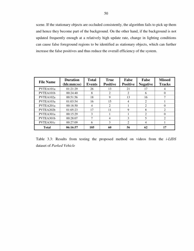
50
scene. If the stationary objects are occluded consistently, the algorithm fails to pick up them
and hence they become part of the background. On the other hand, if the background is not
updated frequently enough at a relatively high update rate, change in lighting conditions
can cause false foreground regions to be identified as stationary objects, which can further
increase the false positives and thus reduce the overall efficiency of the system.
File Name Duration
(hh:mm:ss)
Total
Events
True
Positive
False
Positive
False
Negative
Missed
Tracks
PVTEA101a 01:21:29 26 13 21 17 4
PVTEA101b 00:24:40 8 2 2 6 0
PVTEA102a 00:51:56 18 9 13 16 7
PVTEA103a 01:03:54 16 15 4 2 1
PVTEA201a 00:18:50 4 2 1 2 0
PVTEA202b 01:05:23 17 11 9 8 2
PVTEA301a 00:15:29 3 1 1 2 0
PVTEA301b 00:28:07 7 4 3 5 2
PVTEA301c 00:27:09 6 3 2 4 1
Total 06:16:57 105 60 56 62 17
Table 3.3: Results from testing the proposed method on videos from the i-LIDS
dataset of Parked Vehicle

51
Figure 3.6: Images from the video sequences listed in Table 3.1. (a) PVTEA101a: Level I
video, overcast conditions with rain. Video Quality: Good (b) PVTEA101b: Level I video,
night video sequence with street lights. Video Quality: Good (c) PVTEA102b: Level I
video, day video sequence with changing lighting conditions due to clouds. Video Quality:
Good (d) PVTEA103a: Level I video, day video sequence. Video Quality: Poor (e)
PVTEA201a: Level II video, overcast conditions with video shot at dusk. Video Quality:
Good (f) PVTEA202b: Level II video, overcast with rain. Video Quality: Poor (g)
PVTEA301a: Level III video, overcast conditions with video shot at dusk. Video Quality:
Good (h) PVTEA301b: Level III video, good conditions. Video Quality: Good but with
camera jitter (i) PVTEA301c: Level III video, day video sequence with changing lighting
conditions due to clouds. Video Quality: Good.

52
3.5.2 Edge based Tracking
The second part of the testing process deals with evaluating the performance of the edge
based tracking techniques discussed in Section 3.4.2. Edges are an important tracking
feature, but since they are sensitive to the motion of the object, they are used to track only
stationary objects. Once objects are detected by the background segmentation method and
identified as stationary by the Centroid-Range technique, the edge based tracking technique
is used to lock on to those stationary objects until they move from their stationary position.
In Table 3.1 the results of the proposed method when tested on the PETS dataset are
presented. All the genuine events were detected without any track being lost by the edge
based tracking technique. This is due to the fact that the PETS dataset was recorded in an
indoor environment with controlled lighting conditions.
On the other hand when same technique was tested on outdoor video sequences, it can be
seen from Table 3.3 that out of 60 genuine events detected by the proposed detection
model, the tracking technique missed 17 events. The remaining 43 events were tracked
successfully. The main reason behind these missed events is a sudden change in
illumination conditions. Due to the sudden change in the lighting conditions, the magnitude
of the edges changes causing the correlation peak to fall under the selected threshold value.
Figure 3.7 shows a series of images with one such situation. The normalized correlation
peak values (as defined by equation 3.1) for the tracked object are presented in Figure 3.8.
It can be seen that as the lighting changes from frame 900 onwards, the correlation peak
value falls. This shows that with a sudden change in lighting conditions, the magnitude of
the edges changes thus causing the correlation peak to fall.
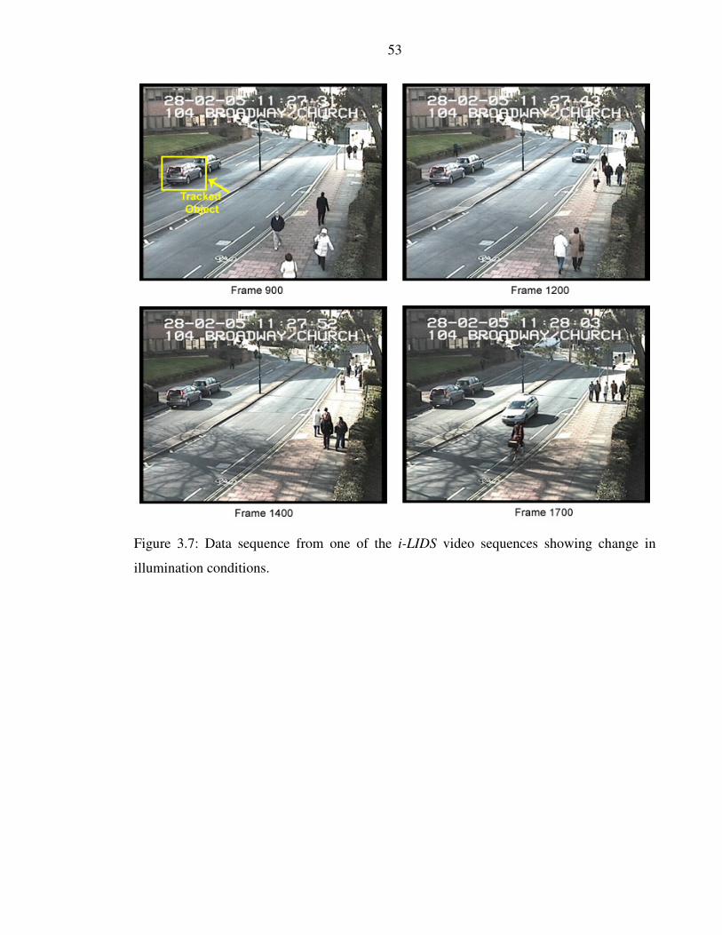
53
Figure 3.7: Data sequence from one of the i-LIDS video sequences showing change in
illumination conditions.

54
Figure 3.8: The effect of the change in lighting conditions (shown in Figure 3.6) on the
correlation results from Frame 900 onwards.
3.6 Conclusion
An edge based tracking technique has been discussed in this chapter where the main focus
is to identify whether the magnitude of image edges is a suitable feature with which to track
objects in different real world scenarios. Since edge features are very sensitive to the
motion of the object, only those objects are considered for tracking that are stationary in the
scene. PETS and i-LIDS datasets are utilized for this purpose, as both datasets provide real
world scenarios for identifying abandoned objects on train stations and illegally parked
vehicles in no-parking zones. A real time two stage approach is adopted in which binary
blobs of foreground objects are initially obtained by using GMM. These blobs of connected
pixels are then tracked until they become stationary. Once they are identified as stationary
objects, by using the Centroid Range method, their edge-map is obtained and stored in a
database for further tracking. In the second stage, an edge-based tracking technique is
applied to track these objects. Correlation peaks are obtained for each of the stationary
55
objects by correlating the current edge map with the reference edge map already in the
database.
The performance of the proposed system is evaluated from two different aspects. Firstly,
the object detection stage is evaluated along with the Centroid Range method to obtain the
overall detection rate of the system. The results obtained, indicate an overall detection rate
of around 57%. It is observed that main reason behind this low detection rate is that the
tracked object is frequently occluded by other moving objects in the scene. As the number
moving objects reduces, the detection rate improves. As an example, this is the case when
the detection model was tested on the PETS dataset, where a 100% detection rate was
obtained as compared to only a 57% rate on i-LIDS dataset.
In the second stage of the evaluation process, the edge based tracking technique is
analyzed. It is observed that in controlled lighting conditions, the magnitude of edge
remains consistent where as it changes with sudden alteration in lighting conditions. This
change causes the correlation peak to fall under the selected threshold thus resulting in loss
of the tracks. Since the i-LIDS dataset is shot in an outdoor environment, where changes in
lighting conditions are unpredictable, 17 lost tracks were recorded as compare to none in
the PETS dataset. Hence it is concluded that in order to track stationary objects in
challenging indoor and outdoor environments, a more robust solution is required. This
could not only detect stationary objects under occlusion but also be able to track them in
changing lighting conditions.
A new pixel based classification technique is discussed in the following chapter that
efficiently detects objects under occlusion. Also, the orientation of the edges in an object is
studied, and compared to their orientation independent magnitude, to find out if edge
orientation is a useful feature to robustly track stationary objects under changing lighting
conditions.

56
Chapter 4
Tracking Objects Using Edge Orientation

57
Chapter 4
TRACKING OBJECTS USING EDGE
ORIENTATION
4.1 Introduction
In the previous chapter it is concluded that, although using the magnitude of edges can
perform better than techniques based on colour features, yet in very inconsistent lighting
conditions when lighting variations are higher than a certain level its performance is
compromised. Such situations can often occur in an environment where the object
recognition and tracking system is deployed in an outdoor scene and thus required to keep
track of the detected object in variable lighting conditions. In order to develop more
intelligent and robust object detection and tracking systems that can be implemented in
both indoor and outdoor environments, a pixel-based classification model is presented in
this chapter to detect objects that become stationary in the scene. These stationary objects
are then tracked using a novel adaptive edge orientation based technique where orientation
of the edge is exploited instead of magnitude to keep track of the stationary object.
Experimental results have shown that the discussed technique gives more than a 95%
detection success rate, even if objects are partially occluded. The technique has been tested
on several hours of video sequences recorded at different locations and time of day, both

58
outdoors and indoors. The results obtained are compared with the technique discussed in
the previous chapter and also with the other available state-of-the-art methods.
4.2 Chapter Organization
The remaining sections of the chapter are organized as follows: Section 4.3 explains the
pixel-based classification method for detection of stationary objects. Tracking is discussed
in Section 4.4 along with some experimental results. Object removal is discussed in Section
4.5. The results of tests on different datasets are presented in Section 4.6 and, finally, the
study is summarized in the final section.
4.3 Stationary Object Detection
As highlighted in the previous chapter, the overall system is divided into two major
sections: detection and tracking. The first stage is to accurately identify stationary objects.
There are several assumptions that have been made regarding the data: the stationary
objects are initially not part of the scene and come in at a later stage; they must be
stationary in the scene for at least 10 seconds before being labelled as stationary and,
finally, they must fall within an ‘Alarm Zone’. Typical ‘Alarm Zones’ for different datasets
is shown in Figure 4.1.
To identify objects that are newly stationary in the scene the moving objects must first be
located and then the tracking stage is triggered when these have become stationary.
Stationary objects detection is therefore a two-step process:
• An initial segmentation of the video sequence using a GMM to determine moving
objects;
• Formation of SHI using this output of the GMM to filter out transitory motion and
determine when an object has become stationary;

59
Figure 4.1: Typical Scenes from different datasets (a) i-LIDS dataset for Abandoned
Baggage (b) ViSOR dataset for Stopped Vehicle Detection (c) PETS 2006 dataset (d) i-
LIDS dataset for Illegally Parked Vehicle Detection. The ‘Alarm Zones’ are marked in red.
The first step uses a GMM to segment the moving objects within the video sequences.
Since the proposed method is required to track the object in real life indoor and outdoor
scenarios, there are a number of unpredictable factors. For instance, for application of the
algorithm to outdoor scenes to identify illegally parked vehicles, change in the illumination
conditions or the starting and stopping of vehicles in busy traffic scenes will cause
difficulties. If the background model is updated at a low rate any sudden change in
illumination can result in the identification of false foreground areas. If the update rate is
higher to cope with the illumination changes, it forces the stationary objects to become part
60
of the background model more quickly resulting in either the partial detection of the
moving object or a completely missed object. On the other hand, for indoor environments
to detect abandoned objects, partial or complete occlusion is the biggest challenge. Most
solutions proposed in the literature require an isolated view of the object before identifying
it as abandoned. This requirement is typically difficult to meet, especially in crowded
scenes where abandoned objects are frequently occluded.
In the proposed method the update rate is set to be high to cope with rapid lighting
variations but Segmentation History Image (SHI) is introduced to post-filter the GMM
output and determine when an object has become stationary.
The output of the GMM produces a set, , of foreground pixels at time t. The SHI data, Γ,
is initially zero then increased by one for every foreground pixel per frame:
(4.1)
Next the objects in motion are removed whilst keeping stationary pixels. This is achieved
by setting the SHI to zero for every pixel not in the current Ωt:
(4.2)
where the bar indicates all pixels not in the current set Ω. This eliminates all those regions
that are moving from the SHI, thus leaving only those pixels that belong to the stationary
objects.
Finally, a pixel is declared as potentially stationary when its SHI value is greater than some
threshold, Λ. Λ is simply the number of frames the system requires to count before
declaring a pixel stationary. In the discussed method, it has been set equal to 10 seconds of
video. The stationary pixels are described by the set S:

61
St = a : Γa > Λ (4.3)
where a is all the possible coordinates in the image.
The SHI effectively acts as a counter to determine when an object has become stationary,
but in addition, by the careful selection of the GMM update rate it can filter out false
objects due to lighting variations. It is noted that lighting changes are typically much
smaller colour changes and often rapid, when compare to vehicles parking. Thus, the
update rate of the GMM can be set such that lighting variations have become part of the
background or have move and are thus removed from the SHI (via equation 4.2), before the
Λ frames have been reached. The choice of the update rate is robust for many different
videos and only need changing if Λ is altered. It does not need changing to cope different
weather conditions or from switching from day to night time lighting. The process is further
elaborated in Figure 4.2 where GMM output is shown in Figure 4.2(a) and the
corresponding SHI in Figure 4.2(b).
It can be seen that the pixel identified as foreground region in Frame 1 are initialised each
with a value equal to 1. As the object moves in Frame 2, the value of the pixels that overlap
a foreground region of the SHI output in the previous frame is increased by 1 where as,
pixels of previous SHI that do not overlap the new GMM output are removed from the SHI.
The process continues until any pixel of the SHI reaches the threshold, Λ. It is important to
note here that the output of the detection technique is based on this threshold value. Only
those pixels are included in the final output that reach Λ. Empirical testing (done over
several hours of video) has shown that in over 95% of the test sequences the effects of
sudden illumination change can be removed if this Λ frames waiting rule is followed.

62
Figure 4.2: (a) GMM output, (b) SHI output.
Figure 4.3 shows a series of images within a typical outdoor scene, the GMM output, SHI
and the final output after thresholding. The car shown in Figure 4.3 was initially not part of
the scene and become stationary at Frame 108. It can be seen that GMM works almost
perfectly if the lighting conditions are consistent (as shown in Frame 108 (b)) and only
legitimate foreground regions are picked up (see GMM output Frame 108 (b)). As the
lighting condition starts changing (see Figure 4.3 Frame 332 and Frame 409) false regions
are picked up as foreground. Frame 409(d) shows the proposed SHI output where pixels
only belonging to stationary object are highlighted as legitimate foreground region in the
final SHI output.

63
Figure 4.3: Images from the i-LIDS dataset for the illegally parked vehicle scenario to
illustrate the detection technique. (a) typical frame (b) GMM output (c) SHI (d) SHI after Λ
thresholding.
After the detection method, a connected component algorithm is run on the binary image,
St, to produce objects, Θn
t where n is the connected component index and Nn ,,1 K∈
where N is the number of connected components discovered. All the connected foreground
pixels are compared against a minimum and maximum object size. Objects that are too

64
small or too large are then removed. The minimum and maximum object size thresholds are
selected based on calibration information.
4.4 Stationary Object Tracking
A new adaptive edge orientation based technique is proposed in this section to track objects
that are identified as stationary. To maintain the tracking, each object at time t is compared
against the object at time T, where T is the time the object is first flagged as stationary by
the SHI (equation 4.3). A correlation based method has been developed that uses the
direction of the edges to indicate the strength of the match rather than the edge strength
alone. A 2-D spatial gradient measure is performed on an image flagged as a stationary
object, IΘn
T, where I is the monochrome image intensity. This is performed by a 3x3 Sobel
convolution operator and is used to find the edges in both the vertical and the horizontal
directions. So that the edge directions are well defined, the magnitude of the gradient is
then calculated at T. This is done by taking the square root of the sum of the squares of each
direction gradient result in Θn
T . Finally the output is thresholded to form a subset of
coordinates, Mn. A higher threshold is chosen such that most of the edges are preserved.
The direction of the gradient of each member of Mn is then calculated by taking the
arctangent of the ratio the vertical and horizontal gradients. It is denoted as ΦMn
T, where
ΦMn
Tcan range between 0 to 360 degree.
The obtained angles are then used to calculate a metric that gives a measure of the degree
of correlation between an object at the current time t and the historic time T. . For the nth
object this is the real component of:
Cn
t =exp iΦMn
t( )exp −iΦMn
T( )Mn
T
Mn
∑ (4.4)

65
where the vertical bars represent the cardinality of the set, and T is the time at which the
reference edge mask is produced. The expression obtained above is the generalized
correlation equation used in the proposed method for template matching. Since the location
of the tracked object is known, the overall computational time is reduced by avoiding the
scanning operation on complete image. The problem arises when the tracked object is
partially or completely occluded. The occlusion problem is discussed in more detail in the
following sub section where improved t
nC)
is obtained by making use of current GMM
segmented object mask, Ωn
t .
4.4.1 Tracking Under Occlusion
The tracking of objects with occlusion is a major challenge faced by any surveillance
application. Tian et al. [34] observed that it is very difficult to get high correlation scores
when objects are frequently occluded. The proposed technique overcomes this issue by
assuming that any current foreground segmented object (from the GMM in stage 1) is a
new occluding object and it should be removed from the set of valid pixels used to calculate
equation (4.4). The occluded region is removed from the mask, Mn, by subtracting the
current GMM segmentation image, Ωn
t . The adaptive mask for the nth
object is a subset of
the original mask:
An
t = Mn −Ωn
t (4.5)
And the improved correlation result is then:
( ) ( )∑
Φ−Φ=
n
nn
At
n
T
A
t
At
nA
iiC
expexpˆ
(4.6)

66
The object is assumed to be tracked when the correlation is above 80% of the auto-
correlation value. The process works efficiently in situations where there is partial
occlusion. If object is completely occluded during the tracking process, the proposed
method waits for p seconds before dropping the object. For situations where a stationary
object is occluded by another object that become stationary, the algorithm will drop the
previously occluded object and will start tracking the new object.
Figure 4.4: Effects of occlusion in a typical Parked Vehicle scenario of the i-LIDS dataset;
(a) typical scene (b) original object mask at the time the object became stationary (c)
original object edge map (d) adaptive binary mask (e) adaptive edge map after applying the
proposed technique.
Figure 4.4 shows images highlighting the effects of occlusion and how the proposed
technique is used to obtain an adaptive edge map and binary mask for the occluded tracked
objects.

67
Figure 4.5: Frame sequence used to compare results from the adaptive edge orientation
based technique with cross correlation as used in Tian et al. [34].
The proposed method is tested on the data presented in Figure 4.5. The results obtained are
compared with the technique presented by Tian et al. [34]. Table 4.1 shows that the
adaptive edge orientation based technique gives over 95% matching results even if the
object is partially occluded as compared to 52% matching results obtained using the cross-
correlation technique, hence demonstrating that proposed method is more reliable for
tracking objects under occlusion.
The researcher notes that if the same adaptive approach was to be applied to other cross-
correlation based techniques there should also be an improvement in performance over that
which has been reported to date.

68
Table 4.1: Matching results after applying the adaptive edge orientation based technique
and the cross- correlation technique to the sequence shown in Figure 4.5.
4.4.2 Tracking under Changing Lighting Conditions
The ability to track objects in changing illumination conditions is another significant
characteristic of the proposed method. For surveillance systems deployed in outdoor
environments, it is very important to accommodate situations where lighting is not
consistent. A change in lighting can not only cause shadows to appear that can falsely
classify pixels as members of ΩΩΩΩ, but it can also change the apparent colour of a tracked
object. This can lead to false tracking results if objects are tracked based on colour features.
Techniques based on the energy or magnitude of the edges, e.g. one discussed in the
previous chapter, can also suffer from changes in illumination. A change in lighting can
cause the magnitude of an edge to change which can result in false tracking outputs. Since
the adaptive edge orientation based technique considers the orientation of the edge rather
than the intensity, and there is no dependency on colour features, it performs better in
conditions where lighting is not consistent, as is now shown in Figure 4.6. The proposed
solution is applied to the data sequence shown in Figure 4.6. The results are compared with
two other tracking techniques based on colour by Piccardi et al. [56] and edge energy,
discussed in the previous chapter. The running average variations in matching over 800
frames are presented in Figure 4.7. It can be seen from Table 4.2 that the matching results
obtained from the proposed solution are consistently better than the other two techniques
throughout the sequence, especially when there is a large change in the illumination
conditions.
Frame
Number
Adaptive edge
orientation match
Cross-correlation
match Tian et al. [34]
1415 98.29% 94.92%
1500 98.05% 57.78%
1580 97.79% 62.28%
1665 98.08% 52.57%

69
Figure 4.6: Data sequence showing change in illumination conditions. The tracked object is
marked in Frame 900. The same sequence was also used in the previous chapter (Figure
3.7).

70
Figure 4.7: Running average variation in matching from frame 900 to frame 1700 for the
three tracking techniques indicated. Edge energy values were taken from Chapter 3, Figure
3.8.
Table 4.2: Running average matching results after applying the adaptive edge orientation
based technique; I-MCHSR and edge energy based tracking techniques on data sequence
shown in Figure. 4.6.
4.5 Object Removal
The algorithm also deals with the removal of objects that are no longer stationary and with
those regions that are falsely identified as static objects. Historic edge maps and tracking
results are analyzed for this purpose. Edge maps for the alarm zones are obtained using the
Frame
Number
Adaptive edge
orientation tracking
Edge energy tracking
Chapter 3
I-MCHSR tracking
Piccardi et al. [56]
900 98.53% 88.54% 95.68%
1200 97.40% 83.43% 76.06%
1400 96.08% 78.51% 71.89%
1700 91.30% 67.54% 60.09%

71
technique proposed in Section 4.4 and stored historically. The frequency of this storage
process depends on the storage capacity of the system implemented; it has been kept to 15
minutes worth of video sequence in this case. For any foreground regions that are labelled
as stationary, edge maps are calculated and matched with the historic edge map database
for the exact pixel location.
The idea is that for any legitimate object, the obtained edge map will always be different
from edge maps stored in the database for the exact pixel location. Experimental results
have shown that although the technique makes the process more computationally
expensive, it significantly reduces the number of false alarms.
It can be argued that the system might fail if a similar shape and size object is parked at the
same location at a different time. For the proposed system to fail;
• the new object has to exactly match the one parked before
• has to be parked at exactly same pixel location as a slight change in the location will
result in a different correlation match
• and finally has to be parked within 15 minutes of the first object left the scene. This
is because the historic edge database is progressively refreshed such that the refresh
process completes after every 15 minutes
If the above three conditions are met, the proposed method will still detect the stationary
object but will fail to track it since it will match the historic edge database.
After the above matching process, regions identified as legitimate foreground objects are
tracked using the adaptive edge orientation based technique and the results are compared
against a chosen threshold. It is observed that when a stationary object moves, the
orientation of the edge map changes and causes matching results to drop below the selected
threshold. This can result in two different scenarios; the tracked object has either left its
stationary position or is occluded by another object. To differentiate between these two
situations, the binary mask overlapping the object’s stationary position is obtained from
most recent GMM output and analyzed. If the mask is originated from within the area of
T
nΘ in terms of pixel location (ghost object) and its total area is also within the area of the
stationary object, the object is assumed to have moved and is no longer tracked. On the

72
other hand if that is not the case, the object is considered to be occluded and the adaptive
edge orientation technique is applied to keep track of the stationary object. Object detection
and tracking results are discussed in more detail in the following section.
4.6 Results and Discussion
The proposed technique has been tested on four different datasets divided into two
scenarios: illegally parked vehicle detection in outdoor scenes and abandoned object
detection at train stations. In both cases the alarm events are generated after 60 seconds of
the object being left stationary. The update rate was selected such that legitimate foreign
objects were categorized as foreground for at least Λ frames before becoming part of the
background. This dependency on Λ frames helps the proposed system not only pick up
stationary objects efficiently but also reduces any affect of sudden illumination change. An
80% matching threshold was selected in order to track the object using the adaptive edge
orientation technique.
This value appeared to work well across all the tested environments with changing lighting
conditions and for any video rate and image quality. If the threshold was set too high or too
low, the tracking results are compromised on platforms with lower image resolution (like
the ViSOR dataset) or poor video quality (some sequences from the i-LIDS dataset). The
thresholds were kept fixed throughout the testing of the proposed system across all four
datasets with different video resolution and quality, viewing angles, lighting conditions
(day or night) and scene density.
4.6.1 i-LIDS Dataset
The algorithm was first evaluated on two sets of Parked Vehicle video sequences from the
i-LIDS dataset, one of which was used in Chapter 3 as well. Both sets contain three
progressively more demanding video sequences, taken at different times of the day. The
first set consists of long video sequences with multiple alarm events with an overall
duration of over 6 hours. The second set contains short video sequences of 2-3 minutes

73
duration with each containing a single alarm event. In both sets the alarm events are
generated after 60 seconds of a vehicle being parked in a prohibited parking zone. Table 4.3
shows results obtained from the long video sequences.
Out of 105 alarm events, the method successfully detected 99 events as compared to 60
events detected by the detection technique used in Chapter 3. It also follows the i-LIDS
requirement to generate the alarm within 10 seconds after the time at which the vehicle has
been stationary for 60 seconds. An overall detection rate of over 90% was achieved by the
algorithm. However, there were 18 false alarms i.e. 15% of the events. This was due to the
fact that no explicit vehicle detection technique has been used to identify whether the
detected object is a vehicle or not. It has been observed that, although application of such a
technique will decrease the number of false alarms, it will not be without a significant
computational cost thus affecting the overall frame rate achievable by the method.
Figure 4.8 shows images from the short video sequences. The proposed method has also
been tested on these videos and results are compared with other state of the art techniques
as shown in Table 4.4. The average error is calculated by comparing the ground truth start
and end times with the acquired results. It can be seen that the system not only runs at over
15 frames/second but also detects illegally parked vehicles more accurately than any other
available method.
Table 4.3 Results which test the proposed method on videos from the i-LIDS
dataset of Parked Vehicle (also used in Chapter 3).
File Name Duration
(hh:mm:ss)
Total
Events
True
Positive
False
Positive
False
Negative
Missed
Tracks
PVTEA101a 01:21:29 26 24 4 2 1
PVTEA101b 00:24:40 8 8 0 0 0
PVTEA102a 00:51:56 18 18 6 0 0
PVTEA103a 01:03:54 16 16 1 0 0
PVTEA201a 00:18:50 4 4 1 0 0
PVTEA202b 01:05:23 17 14 2 3 0
PVTEA301a 00:15:29 3 3 2 0 0
PVTEA301b 00:28:07 7 6 1 1 0
PVTEA301c 00:27:09 6 6 1 0 0
Total 06:16:57 105 99 18 6 1
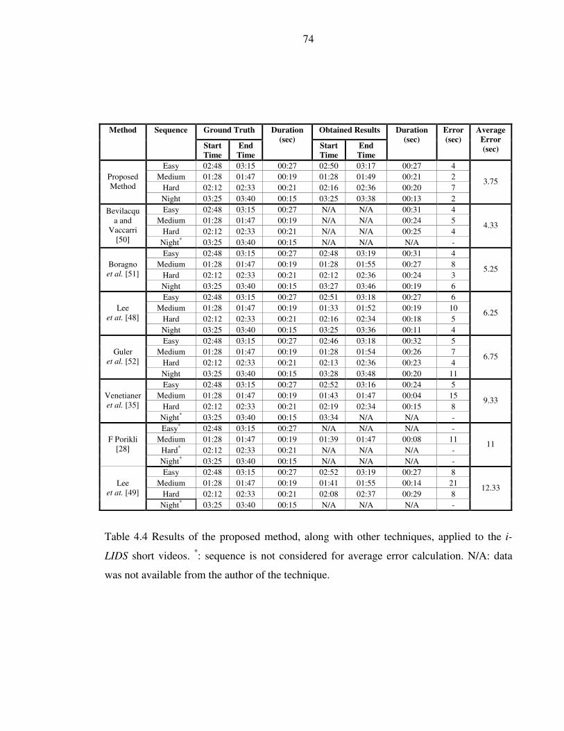
74
Table 4.4 Results of the proposed method, along with other techniques, applied to the i-
LIDS short videos. *: sequence is not considered for average error calculation. N/A: data
was not available from the author of the technique.
Ground Truth Obtained Results Method Sequence
Start
Time
End
Time
Duration
(sec) Start
Time
End
Time
Duration
(sec)
Error
(sec)
Average
Error
(sec)
Easy 02:48 03:15 00:27 02:50 03:17 00:27 4
Medium 01:28 01:47 00:19 01:28 01:49 00:21 2
Hard 02:12 02:33 00:21 02:16 02:36 00:20 7
Proposed
Method
Night 03:25 03:40 00:15 03:25 03:38 00:13 2
3.75
Easy 02:48 03:15 00:27 N/A N/A 00:31 4
Medium 01:28 01:47 00:19 N/A N/A 00:24 5
Hard 02:12 02:33 00:21 N/A N/A 00:25 4
Bevilacqu
a and
Vaccarri
[50] Night* 03:25 03:40 00:15 N/A N/A N/A -
4.33
Easy 02:48 03:15 00:27 02:48 03:19 00:31 4
Medium 01:28 01:47 00:19 01:28 01:55 00:27 8
Hard 02:12 02:33 00:21 02:12 02:36 00:24 3
Boragno
et al. [51]
Night 03:25 03:40 00:15 03:27 03:46 00:19 6
5.25
Easy 02:48 03:15 00:27 02:51 03:18 00:27 6
Medium 01:28 01:47 00:19 01:33 01:52 00:19 10
Hard 02:12 02:33 00:21 02:16 02:34 00:18 5
Lee
et at. [48]
Night 03:25 03:40 00:15 03:25 03:36 00:11 4
6.25
Easy 02:48 03:15 00:27 02:46 03:18 00:32 5
Medium 01:28 01:47 00:19 01:28 01:54 00:26 7
Hard 02:12 02:33 00:21 02:13 02:36 00:23 4
Guler
et al. [52]
Night 03:25 03:40 00:15 03:28 03:48 00:20 11
6.75
Easy 02:48 03:15 00:27 02:52 03:16 00:24 5
Medium 01:28 01:47 00:19 01:43 01:47 00:04 15
Hard 02:12 02:33 00:21 02:19 02:34 00:15 8
Venetianer
et al. [35]
Night* 03:25 03:40 00:15 03:34 N/A N/A -
9.33
Easy* 02:48 03:15 00:27 N/A N/A N/A -
Medium 01:28 01:47 00:19 01:39 01:47 00:08 11
Hard* 02:12 02:33 00:21 N/A N/A N/A -
F Porikli
[28]
Night* 03:25 03:40 00:15 N/A N/A N/A -
11
Easy 02:48 03:15 00:27 02:52 03:19 00:27 8
Medium 01:28 01:47 00:19 01:41 01:55 00:14 21
Hard 02:12 02:33 00:21 02:08 02:37 00:29 8
Lee
et at. [49]
Night* 03:25 03:40 00:15 N/A N/A N/A -
12.33

75
Figure 4.8: Images showing detection scenarios from short video sequences (a) PV Easy (b)
PV Medium (c) PV Hard (d) PV Night.
The algorithm was also tested on three Abandoned Baggage video sequences from the i-
LIDS dataset. Alarms were generation if the object is left stationary for over 60 seconds
irrespective of whether it had been left unattended or not. Individual frames taken from
these sequences are shown in Figure 4.9. All the events were successfully detected by the
system with a low number of false positives. In order to avoid alarms that can be generated
by people standing on the platform and staying stationary for longer durations of time, a
minimum-maximum object size filter is applied. The position of the object was calculated
and compared with minimum-maximum object size at that perspective position in the
frame. Although the technique is simple it removes over 60% of the false alarms generated
in such situations. The overall results of the algorithm are shown in Table 4.5. The two
false alarms identified in the “hard video” sequence are, in fact, bags on the floor with their
owners sitting next to them. Since the proposed method does not associate people with
bags, it has been put under the false positive category.

76
Figure 4.9: Images from Abandoned Baggage scenario (a) AB-Easy (b) AB-Medium (c)
AB-Hard.
Table 4.5 Results obtained after testing the proposed system on Abandoned Baggage
sequences from the i-LIDS dataset.
4.6.2 MIT Dataset
The MIT traffic dataset is a research dataset used to analyze activities in crowded traffic
scenes. Although it has not been shot specifically for identifying illegally parked vehicles
on the side of road, there are two instances when a car stops on the side of the road. In the
first instance the car stays stationary for 4 minutes and 7 seconds and in the second
sequence it stays stationary for only 13 seconds. The overall duration of the video is 90
minutes the algorithm has only been tested on the first 10 minutes in which the two relevant
events occur. The discussed method successfully detected both events without any false
alarms but only generated one alarm (as alarms are only generated if an object is stationary
for over 60 seconds). The same threshold values are kept as when tests were carried out on
Sequences True
Positive
False
Positive
False
Negative
AB-Easy 1 0 0
AB-Medium 1 3 0
AB-Hard 1 2 0
Total 3 5 0

77
the i-LIDS video sequence of Parked Vehicle. Figure 4.10 shows images from the MIT
Traffic Dataset, highlighting both events that were successfully detected.
Figure 4.10: Images from the MIT Traffic Dataset where events are detected when vehicles
are parked on road sides.
4.6.3 ViSOR Dataset
The algorithm was also tested on the Stopped Vehicles Detection scenario of the ViSOR
dataset. The dataset consists of four 2-3 minute video sequences each containing multiple
events. All four sequences show scenes from a parking lot. The alarm events are generated
for vehicles that are stationary for over 60 seconds in places other than those designated for
parking. In the first video sequence two vehicles enter the scene. The algorithm picks up
both events but does not generate any alarms as the vehicles are parked in the designated
parking areas. In the second and third video sequences, an alarm event is generated for each
sequence after a vehicle is found stationary for more than 60 seconds in a no parking area.
In the final sequence, a single event is detected but no alarms are generated as the stopped
vehicle leaves the scene within 60 seconds of being stationary. Figure 4.11 shows images
from all four video sequences containing the detected events. The proposed algorithm
detected all the events with no false alarms.

78
Figure 4.11: Images from the ViSOR Dataset (a) Sequence 1 (b) Sequence 2 (c) Sequence 3
(d) Sequence 4. All events are detected with no false positives and alarms are generated for
vehicles stationary for over 60 seconds in (b) and (c).
4.6.4 PETS 2006 Dataset
The overall results of the proposed algorithm when it was tested on the PETS 2006 dataset
are summarized in Table 6. The same sequences were also used in Chapter.3, comparisons
being made with the results obtained from Chapter 3 and other available state of the art
methods. Table 4.6 shows that the proposed method picks up all the genuine alarms without
generating any false alarms. When compared with the other available techniques, it can be
seen that the method produces very accurate results (equal to those reported by Chang et al.

79
[53]). Although Lv et al. [54] also produced 100% results, no information about false
alarms was reported by the authors.
Table 4.6: Results obtained after testing the proposed method along with other published
methods on all the sequences from the PETS 2006 dataset. N/A: data was not available
from the author of the technique.
4.7 Conclusion
A robust stationary object detection system has been presented in this chapter. Two major
concerns faced by such techniques, namely lighting variations and occlusion, are addressed.
A new pixel based classification method based on GMM is initially used to detect
stationary objects where SHI was utilized to overcome difficulties caused by variable
lighting effects. Once objects are identified as stationary, an adaptive edge orientation
based tracking technique is applied to track objects under severe lighting conditions and
occlusion. The study has demonstrated that the proposed tracking method has an accuracy
of over 95% matching results under occlusion as compared to less than 70% accuracy
achieved by the other available state of the art methods. Finally, objects that are no longer
stationary or are falsely identified as stationary objects are removed by analyzing historic
edge maps and tracking results.
The proposed method was tested on four different datasets. Overall over seven hours of
video, recorded at different locations and at different times of the day have been used for
Methods Total
Alarms True Positive False Positive False Negative
Proposed Method 6 6 0 0
Chapter 3 Results 6 6 2 0
Tian et al. [34] 6 6 1 1
Auvinet et al. [55] 6 6 5 0
Chang et al. [53] 6 6 0 0
Lv et al. [54] 6 6 N/A 0

80
this purpose. Out of 121 genuine alarms across all the video sequences, the proposed
technique picks up 115 alarms, giving an overall detection rate of over 95% as compared to
57% reported in the previous chapter. Also, unlike the technique presented in Chapter 3
where 56 false alarms were recorded, it only produced 23 false alarms i.e. reducing this by
a half. This shows that not only is the performance of the proposed method strong but also
that it is adaptable to different indoor or outdoor environments. Another important
characteristic revealed by the experiments is the reduction in the number of missed tracks.
Missed tracks are events that occur when the object is detected but its track is lost by the
tracking technique. The adaptive edge orientation based technique misses out only a single
object as compared to the magnitude based technique where 17 tracks were lost.
The techniques discussed in this chapter, and also in Chapter 3, are specifically designed to
track rigid objects that become stationary in the scene. Keeping in view this implementation
environment, edge maps are utilised as they are a useful feature that remains consistent
throughout the tracking process. Since edge maps are sensitive to the shape of the object, as
soon as an articulated or non-rigid object moves the edge map changes. Thus in order to
track non-rigid moving objects, a different approach is required. The following two
chapters highlight techniques designed to track such objects in crowded scenes. In that the
particle filter has been used and solutions are designed to be implemented in multi-camera
environments.

81
Chapter 5
An Adaptive Sample Count Particle Filter

82
Chapter 5
AN ADAPTIVE SAMPLE
COUNT PARTICLE FILTER
5.1 Introduction
In Chapter 2, colour and edge information was highlighted as two major features used for
tracking objects in crowded scenes. Since edge information is sensitive to the motion of the
object, it is usually useful to track objects with consistent edge features as shown in Chapter
3 and 4. In order to track non-rigid moving objects such as humans, edges are usually not a
practical attribute and colour features are exploited in such situations. Particle filtering
techniques have been used extensively over the past few years in this regard. Due to its
nonlinear nature and the fact that it does not assume a Gaussian probability density, it tends
to outperform other available tracking methods.
A novel adaptive sample count particle filter (ASCPF) tracking method is presented in this
chapter for which the main motivation is to accurately track an object in crowded scenes
using fewer particles and hence with reduced computational overhead. Instead of taking a
fixed number of particles, a particle range technique is used where an upper and lower
bound for the range is initially identified. Particles are made to switch between an active
and inactive state within this identified range. The idea is to keep the number of active
particles to a minimum and only to increase this as and when required. This, together with

83
the variable particle spread, allows a more accurate proposal distribution to be generated
while using less computational resource. Experimental results show that the proposed
method not only tracks the object with comparable accuracy to existing particle filter
techniques but is up to five times faster.
5.2 Chapter Organization
The chapter is organized in the following way. The problem is defined and discussed in
Section 5.3. This section highlights the major observations made regarding drawbacks in
current particle filtering techniques and outlines an overall framework of how the solution
is improved. The in-depth computational model is discussed in Section 5.4, where the
modifications proposed at each stage of the particle filter are explained. Results are
presented in Section 5.5 where comparisons are made with the standard Sequential
Importance Resampling (SIR) particle filter technique followed by a discussion in Section
5.6. The study is finally concluded in Section 5.7.
5.3 Motivation
Tracking moving objects, especially humans in different environments, is an important part
of any video surveillance application. Human tracking has been the focus of many studies
in the past but due to its nonlinear nature it is still a challenging task. Particle filtering has
been used extensively to solve this problem. The basic idea of the particle filter is to
estimate the state of the moving object, given previous states and measurements, using
Monte Carlo simulations (see Appendix B for details). Samples (particles) are drawn from a
proposal distribution and weighted to try to estimate the posterior density. Theoretically,
the higher the number of particles the more accurate will be the tracking results. However,
this does not work in all situations, as discussed later in the chapter, and also a higher
number of particles do not come without computational cost.

84
It has been observed that in order to design a particle filter for any application, it is the
choice of proposal distribution that is critical. The proposal distribution depends on the
quality of the particles. Good quality particles or, in other words, particles with higher
weights will give a more accurate a posteriori density, which will result in a more accurate
proposal distribution. However, it is very important to strike a balance between good
quality proposal distributions, which in theory can be obtained by a higher number of
particles and computational cost.
Another important observation has been made regarding the adoption of particle filters. The
solutions proposed so far use a single standard deviation value for each of the state
elements to spread the particles [104]. It has been observed that this works well under most
conditions but can cause difficulties when the object is frequently occluded.
Motivated by the above findings, an effort has been made to improve the performance of
particle filters by taking three important measures:
• Identification of the appropriate particle range for tracking a particular object.
• The concept of adaptive samples is introduced to keep the computational cost down.
• Variable standard deviation (σ) values for state vector elements have been exploited
to cope with frequently occluded objects.
The aim is to track an object in crowded scenes to get similar, if not better; tracking results
to those reported to date whilst simultaneously using fewer particles and thus keep the
computational cost down.
Commonly the techniques proposed in the literature select a fixed number of particles to
track objects. In order to keep the computational cost down, the concept of active particles
has been introduced. A similar concept was demonstrated by Linzhou et al. [106] but the
method did not handle any occlusion. Similarly a Kullback-Leibler Distance Sampling
(KLD-Sampling) algorithm was presented by Fox et al. [107] that adaptively estimated that
number of particles. The method was later further improved by Soto et al. [108]. Although
the improved method provided a self adaptive sampling mechanism with better allocation
of particles under the likelihood function, it does not improve the performance of the
overall system in terms of computational cost. In the proposed method, particles are made

85
to switch between two states: active (on) and inactive (off). Once the observation is
available and particle weights are updated, resampling is performed to solve the degeneracy
problem. If the effective number of particles is less than a certain threshold, the particles
are resampled and the number of active particles is set to a minimum by eliminating
particles with low weights. It has been reported in [105] that typically a minimum of 50
particles are required to effectively represent the shape of the tracked object. Although
these findings were obtained from a different perspective (to determine a football player
shape and not for tracking), the same criterion is investigated in Section 5.4.1.2 to
determine whether it could be used as a minimum number to keep track of a moving object.
The remaining particles are made active in the subsequent steps depending on the output of
the resampling step. This clearly helps to reduce the computational cost as fewer particles
are used to track the object.
To track the moving objects that are frequently occluded in a crowded scene, a variable
particle spread method is proposed. As particles are switched between active and inactive
states, there can be situations where the number of particles might be less than a desired
number, especially when objects are frequently occluded. To minimize the effect of such
situations the standard deviation value for the position vector is increased at each step along
with the number of active particles. This helps spread the particles to wider areas and
effectively minimizes any limitations of using fewer particles. As the resampling threshold
is met, the standard deviation value, as well as the active number of particles, is set to a
minimum.
5.4 Computational Model
The overall computational model and modifications made to the standard particle filter are
presented in this section. The appropriate particle range for tracking a particular object is
initially identified. Once the upper and lower limits for this range are obtained, the
proposed particle filter technique is applied, discussed later in this section, to track a single
object in different environments.

86
5.4.1 Identification of Particle Range
Although the particle filter has been the focus of many studies in the past decade, not much
emphasis has been given to how many particles are appropriate for tracking a particular
object. Most techniques proposed in the literature take a fixed number of particles, N,
irrespective of the object being tracked. This can result in an additional computational cost
if N is higher than required or false tracking outputs if it is too low. A new particle range
method is discussed in this section, where the number of particles is switched between an
active and inactive state within an identified range.
5.4.1.1 Identification of the Maximum Number of Particles (Nmax)
Theoretically, it has been observed the higher the number of particles the more accurate is
the proposal distribution. Different authors have selected different N value for their
experiments. It has been observed that although a higher number is desirable, it is not
always required as higher number of samples will result in higher computational cost. In
the proposed method, this value (upper limit of the particle range Nmax) is even less
important as it is only acting as an upper limit to the number of samples that will be used to
track an object. Nmax for the proposed method is selected as 250. Experiment results
presented later in this paper further strength this argument as this upper limit of 250 is not
reached even once during the tracking experiments on all 8 sequences.
5.4.1.2 Identification of the Minimum Number of Particles (Nmin)
As particles are switched between active and inactive states, such that Nmin ≤ Nactive (where
Nactive ≤ Nmax), it is very important to identify a reasonable minimum number of particles
Nmin to track the object in different situations. It was reported in [105] that typically a
minimum of 50 particles are required to effectively represent the shape of the tracked
object. The same observation has been taken into consideration and further tested on four
Nmin value tracks (30, 50, 75 and 100 particles) on the different video sequences shown in
Figure 5.1. The complexity of the video sequences is based on scene density as well as

87
frequency with which the tracked object is occluded. The idea is to identify an appropriate
minimum number of particles Nmin such that it not only allows the system to track the
object accurately in different surroundings but also keeps the computational cost down.
Figure 5.2 shows an average pixel error graph obtained after four Nmin values are tested and
compared against the ground truth data.
The track with 30 particles produces the highest pixel error results for all the sequences,
especially where there is frequent occlusion. This is evidently due to the use of fewer
particles as compared to other tracks. On the other hand, the remaining three tracks with the
Nmin value equal to 50, 75 and 100, produce almost similar error results with an average
pixel error difference of around 2 pixels. This shows that if the number of particles is
higher than a certain number (50 in this case) the tracking outputs are almost similar with
minimal average pixel error difference. This indicates that it is not the quantity of particles,
but their quality that is important for the accuracy of the track produced by the particle
filter.
Table 5.1 presents the average computational time along with the average pixel error
calculated for the four tracks on all the video sequences. Although the track with 30
particles yields a faster computational time, the corresponding average pixel error is quite
high. On the other hand, the track with 100 particles produces almost half the pixel error as
compared to the 30 particle track but it is almost four times slower. If track with 50
particles is analyzed , it can be seen that not only is it, on average, around two pixels adrift
from the 100 particle track but it is also twice as fast. Hence, 50 particles is an appropriate
value for Nmin for the proposed system due to the resulting accuracy and fast computational
time.
Once Nmax and Nmin are determined, particles are normally distributed to
obtain max
1
)(
0
)(
0 ,N
i
iiwx = , and so form an estimate for )( 0xp . Here, )(
0
ix is the state vector that
includes the x and y Cartesian coordinate position of the object, )(
0
iw is the weight assigned
to each particle and max,.....,1 Ni = . Once Nmax and Nmin are calculated they are kept fixed
throughout the tracking process.

88
Figure 5.1: Image from four test sequences used to identify appropriate Nmin value for the
proposed system (a) scene with no occlusion (b) scene with low occlusion (c) scene with
medium occlusion (d) scene with high occlusion

89
Figure 5.2: Average pixel error graphs obtained after comparing the tracking results with
ground truth data on all four video sequences
Table 5.1: The pixel error and computational time results to identify Nmin
Average Pixel Error (in pixels) Sequence
(Occlusion) Track 1
(30 Particles)
Track 2
(50 Particles)
Track 3
(75 Particles)
Track 4
(100 Particles)
No 11 7 6 6
Low 14 10 8 7
Medium 15 10 8 7
High 18 11 10 9
Computational Time (in ms)
Track 1
(30 Particles)
Track 2
(50 Particles)
Track 3
(75 Particles)
Track 4
(100 Particles)
No 31.4 62.7 94.1 129.2
Low 49 79 124.3 174.4
Medium 37 70.8 102 137
High 32 62.6 97.6 135.1

90
5.4.2 State Model
The state of the object is represented by:
11 −− += kkk vFxx (5.1)
where, F is the transition matrix and 1−kv is the additive white, zero-mean, Gaussian noise,
irrespective of the object state and kx is the state vector.
5.4.3 Prediction Model
It was observed by Dearden and Demiris [104], that the proposal distribution is critical for
the design of any particle filter. A good proposal distribution comes with high quality
particles. One way of achieving this is by having a good prediction mechanism.
The state information is predicted separately for both x′ and y′ coordinates:
xkkk vxxxp +∝−
'
1
' )( (5.2)
ykkk vyxyp +∝−
'
1
' )( (5.3)
where xv and yv is zero-mean, Gaussian noise with variable standard deviation, σ . The
variable σ value allows the particles to spread to wider areas and hence avoid tracking
difficulties under occlusion. Since fewer particles are proposed to track the object, there
may be situations where the object gets occluded. These situations are often unpredictable.
The proposed method in such situations will end up having fewer particles to find the
object again (as under no occlusion Nactive is likely to be near or equal to Nmin). It has been
observed that this is the major limitation of having fewer particles. To overcome this
limitation, a new variable particle spread method is introduced which increases the spread
of the particles to wider areas as soon as the object gets occluded. Thus when the object is

91
occluded, the spread of the particles is increased to cover more area, so helping overcome
any limitation of having fewer particles. During occlusion all the particles end up having
similar weights as no particle is able to locate the object.
This results in an increase in the effective sample size, Neff. As Neff increases and reaches a
point where it is no longer less than the threshold Nth (explained in Section 5.4.5) the
number of particles along with their standard deviation is increased to spread the available
active particles to a wider area to overcome any limitation of having fewer particles. The
usefulness of this method is further elaborated in Section 5.5.2, where to find the
effectiveness of the variable standard deviation approach, the results of the adaptive
sampling method that incorporates the variable standard deviation are compared with the
adaptive sampling method with constant standard deviation.
5.4.4 Update Model
At time k, when the measurement zk is available, the update step is carried out. A colour
based likelihood model is used for this purpose. Although the technique could be used with
other metrics, a colour histogram for the tracked object is calculated for each particle using
the current frame. Comparison with the reference histogram is used to compute the
Bhattacharyya coefficient [115], where )','()()( i
k
i
k yx is considered as the centre of the region.
If the likelihood is modelled as a Gaussian distribution for the Bhattacharyya distance, then
)( kk xzp is given by:
)( kk xzp = 2
2
2
22
1σ
σπ
kD
e−
′
(5.4)
where the standard deviation, σ ′ , is kept very low, such that if two objects of similar
colour cross over, the particles remember their original tracking colour histogram so when
the objects separate they follow the correct path. kD is the Bhattacharyya distance
calculated as:
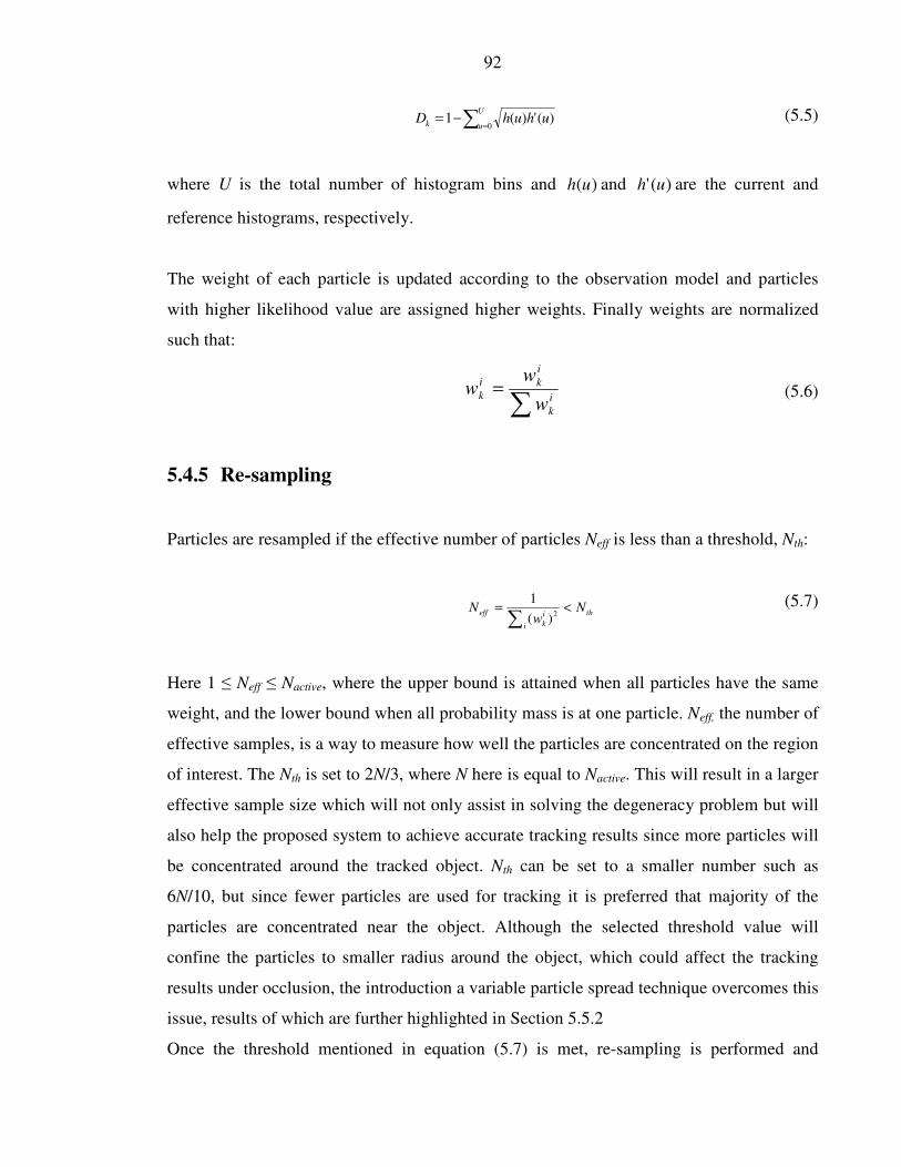
92
∑ =−=
U
uk uhuhD0
)(')(1 (5.5)
where U is the total number of histogram bins and )(uh and )(' uh are the current and
reference histograms, respectively.
The weight of each particle is updated according to the observation model and particles
with higher likelihood value are assigned higher weights. Finally weights are normalized
such that:
∑=
i
k
i
ki
kw
ww (5.6)
5.4.5 Re-sampling
Particles are resampled if the effective number of particles Neff is less than a threshold, Nth:
th
i
i
k
eff Nw
N <=∑ 2
)(
1 (5.7)
Here 1 ≤ Neff ≤ Nactive, where the upper bound is attained when all particles have the same
weight, and the lower bound when all probability mass is at one particle. Neff, the number of
effective samples, is a way to measure how well the particles are concentrated on the region
of interest. The Nth is set to 2N/3, where N here is equal to Nactive. This will result in a larger
effective sample size which will not only assist in solving the degeneracy problem but will
also help the proposed system to achieve accurate tracking results since more particles will
be concentrated around the tracked object. Nth can be set to a smaller number such as
6N/10, but since fewer particles are used for tracking it is preferred that majority of the
particles are concentrated near the object. Although the selected threshold value will
confine the particles to smaller radius around the object, which could affect the tracking
results under occlusion, the introduction a variable particle spread technique overcomes this
issue, results of which are further highlighted in Section 5.5.2
Once the threshold mentioned in equation (5.7) is met, re-sampling is performed and

93
particles with insignificant weight are removed. Apart from resampling, three other
important steps are implemented:
• The number of active particles Nactive is set to Nmin. This helps reduce the
computational cost. As particles concentrate on the region occupied by the tracked
object there is no need to use a higher number of active particles hence Nactive is set
to a minimum. If the condition in equation (5.7) is false, the number of active
particles Nactive is increased from the minimum by a percentage such that Neff is
greater than Nmin (until a limit of Nmax is reached).
• The x and y standard deviation values of the state vector are reduced to a minimum.
If equation (5.7) is false, the value of the standard deviation is increased by 10%.
This 10% is a design parameter and can be changed in different environments.
These changes to the resampling step not only reduce the number of active particles and
hence reduce the overall computational cost but also help improve the proposal distribution.
The overall implementation of the proposed particle filter technique is summarized in Table
5.2.

94
Table 5.2: Overview of proposed Adaptive Sample Count Particle Filter method
Proposed Particle Filter Method
1. Initialization
• Manually select the object to be tracked
• Generate Nmax samples to obtain
• Set Resampling Flag to true
2. For every incoming frame
Predict
• Distribute particles using equation (5.2) and (5.3)
Update
For all active particles
• Compute )( kk xzp using equation (5.4)
• Computer independent weights
• Normalize weights using equation (5.7)
Resample
If equation (5.7) is true
• Resample
• Obtain mean value for x and y for all active particles
• Reduce the number of active particles to a minimum
Reduce sigma value for xv and yv in equation (5.2) and (5.3) to a minimum Else
• Obtain mean value for x and y for all active particles
• Increase active particles until Nmax is reached
• Increase sigma value for xv and yv in equation (5.2) and (5.3) by 10%
3. Go to Step 2
max
1
)(
0
)(
0 , N
i
iiwx =

95
5.5 Results and Discussion
The performance of the proposed technique is evaluated in terms of computational cost and
tracking accuracy by conducting several experiments on the PETS [7], i-LIDS [4] and
University of Sussex Tracking [9] datasets. Although both the PETS and the i-LIDS datasets
are designed for tracking objects in multi camera environments, only single camera view is
focused in this chapter. In total over 9,000 frames worth of video sequences were used for
the evaluation with a single object being tracked in each sequence. These sequences were
divided into three categories: sequences with partial and complete occlusion; sequences
with change in scale of the tracked object; and sequences with variable target motion. The
results obtained are compared with the tracking results of the standard SIR particle filtering
method.
The tracking procedure for the proposed method starts with the manual selection of the
object to be tracked. Once the object has been selected, the maximum number of particles,
Nmax is set to 250 where as minimum number of particles Nmin is set to 50 as explained in
Section 5.4.1. Finally, the minimum standard deviation value for vx and vy in equations
(5.3) and (5.4) was set to 0.6.
The results for the SIR particle filtering method are obtained by keeping the Nmin, Nmax and
Nactive, equal to 250 and the standard deviation value for xv and yv equal to 0.6.
5.5.1 Video Dataset
The datasets used for the evaluation of the proposed technique are selected keeping in mind
the complexities of real world scenarios. The PETS and i-LIDS datasets provide benchmark
video sequences for the development of techniques that are robust to real world tracking
problems. Although the PETS and i-LIDS datasets are recorded to track objects in crowded
scenes, where there are frequent occlusions, there are certain situations which were not
covered by both datasets that were thought useful for inclusion in order to allow further
evaluation of the tracking system performance. University of Sussex Tracking dataset has
been used for this purpose which includes video sequences for scenarios where scale and
motion of the target object are not consistent. In total over 9,000 frames worth of data
96
including sequences from the PETS and the i-LIDS datasets, divided into 3 categories.
Comparisons are made with the SIR particle filter method in terms of computational cost
and tracking accuracy. The accuracy of the tracking results are analyzed by comparing
them with the ground truth, which was obtained by manually clicking the centroid of the
target object. The tracking accuracy measure was the pixel error difference between the
obtained values and the ground truth x and y locations calculated from:
2
12
2
12 )()( yyxxError −+−= (5.8)
where (x1,y1) are the coordinates of ground truth data and (x2,y2) are the coordinates of data
obtained from each the SIR and the proposed method.
The computational time was obtained by calculating the time taken by both techniques for
each frame (in milliseconds).
5.5.2 Frequent Occlusion
Occlusion is one of the major challenges faced by any tracking technique. Particle filtering
methods in general tends to out-perform other tracking techniques in such situations due to
their adaptive nature, provided occlusion is not 100%. Since fewer particles are proposed in
this experiment to track the object, there can be situations where the number of particles is
less than the desired number, especially when the tracked object is partially or completely
occluded. As particles are gradually increased from Nmin to Nmax the increase can cause the
computational time to go up and in some cases can still not generate enough particles to get
accurate tracking results. To overcome such situations, the use of a variable standard
deviation value for x and y position vectors given in equation (5.2) and (5.3) are proposed.
This variable standard deviation value not only helps fewer particles to spread to wider
regions but can also improve the proposed system’s tracking capabilities under occlusion.
To further investigate the proposed method, different video sequences of variable lengths
are considered where the tracked object is frequently occluded. The proposed method is
tested on these sequences and results in terms of computational time and tracking accuracy

97
are compared with the standard SIR particle filter method. In order to find the effectiveness
of the variable spread method under occlusion, an adaptive sample method is applied
without the variable spread approach on the same sequences and compared to the results
obtained with those of the proposed technique. This is to verify that the adaptive sampling
approach alone is not as effective as when combined with the variable spread technique
both in terms of computational cost and tracking accuracies.
Figure 5.3, 5.4 and 5.5 show images along with the tracking results from the three
evaluated methods. These three methods are categorized as the proposed method (the
proposed method with variable particle spread), the particle filter without variable spread
(the method that only incorporates the adaptive sample approach but not the variable
spread) and the standard SIR particle filter method.
The top graph shown in Figure 5.3, 5.4 and 5.5 represents the pixel error per frame,
calculated by comparing the ground truth data with the x and y position value of the tracked
object obtained from the three techniques. The middle graph shows the number of active
particles, Nactive, used by all the three methods; the bottom graph shows the ground truth
meta data about the object i.e. whether the object is occluded, not occluded or partially
occluded at each frame. Table 5.3 shows the summary of the results obtained from these
techniques. It can be seen that the proposed method is the most effective in terms of
computational cost. The graphs showing number of active particles (centre graphs) in
Figure 5.3, 5.4 and 5.5 support this conclusion as they show that the number of particles
used by the proposed method is significantly less than the method without the spread
function and also the standard SIR particle filter method (that utilized 250 particles for
tracking).
In terms of tracking accuracy the proposed technique is on average less than two pixels
adrift from the standard particle filter method but six times faster. If the tracking results for
the method without the spread function are compared with the ground truth data, it can be
seen that this results in over ten pixels of error, almost five times more than the proposed
method.

98
Average Pixel Error
per Frame (in pixels)
Average Computational Time
per Frame (in ms)
Sequence No of
Frames Proposed
Method
Standard
Particle
Filter
Method
Proposed
Method
without
Variable
Particle
Spread
Proposed
Method
Standard
Particle
Filter
Method
Proposed
Method
with out
Variable
Particle
Spread
I 507 12 11 36 53.6 298.5 77.3
II 1987 12 10 12 67.1 335.3 92.5
III 383 13 9 14 57.6 352.5 74.5
Table 5.3: Average Pixel Error and Computational Cost for each technique when applied on
sequences shown in Fig. 5.3, 5.4 and 5.5
Figure 5.3: Tracking results from the 1st video sequence. The top graph shows the pixel
error per frame when compared with ground truth data, the middle graph shows the number
of active particles used by the proposed method and the bottom graph shows the state of the
tracked object at each frame
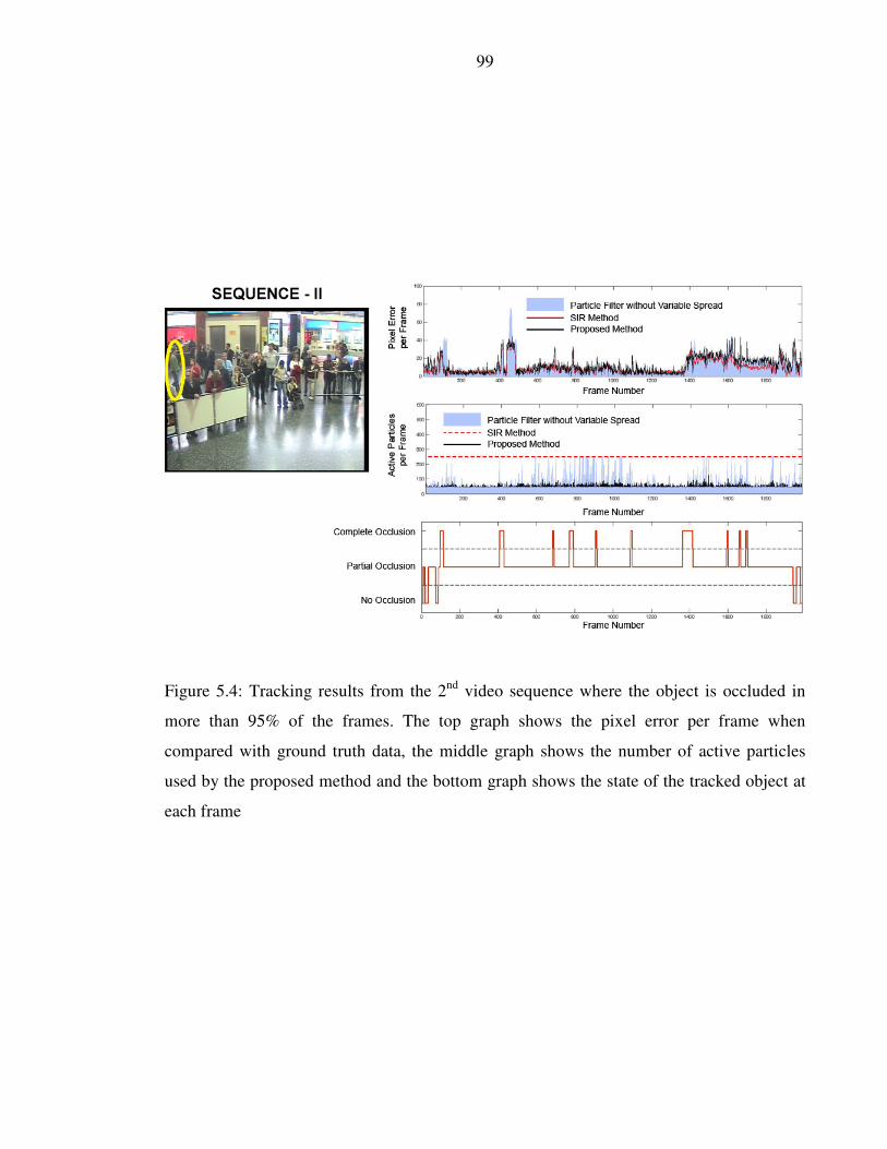
99
Figure 5.4: Tracking results from the 2nd
video sequence where the object is occluded in
more than 95% of the frames. The top graph shows the pixel error per frame when
compared with ground truth data, the middle graph shows the number of active particles
used by the proposed method and the bottom graph shows the state of the tracked object at
each frame
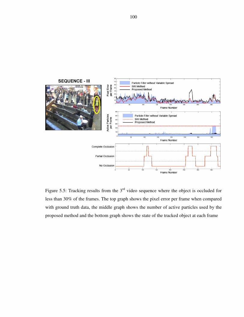
100
Figure 5.5: Tracking results from the 3rd
video sequence where the object is occluded for
less than 30% of the frames. The top graph shows the pixel error per frame when compared
with ground truth data, the middle graph shows the number of active particles used by the
proposed method and the bottom graph shows the state of the tracked object at each frame

101
5.5.3 Scale Variation
To evaluate the proposed method in situations where the scale of the object in not constant,
two video from University of Sussex Tracking dataset [9] has been used. The first sequence
is approximately 1,200 frames long and the second sequence is approximately 700 frames.
The scale of the object changes as it moves away from the camera. Figure 5.6 and 5.7 show
images from both sequences to highlight the scale variations. It has been observed that
although the scale of the object varies quite considerably during the tracking process, this
does not have any significant affect on the tracking accuracy. This is the case for both the
proposed method and the SIR particle filter method.
From Figure 5.6 and 5.7 it was observed that on average the proposed method is 12 pixels
in error whereas the SIR method is 11 pixels in error with respect to the ground truth data.
Although the tracking results for the proposed method are slightly in more error the
computational cost on the other hand is considerably less than the standard approach. This
highlights the minimal effect of the reduced number of particles on tracking accuracies
when the object scale is not constant.

102
Figure 5.6: Tracking results from the 4th video sequence. The series are images in the top
row shows the variation in object scale as it moves away from the camera. The first graph
shows the pixel error per frame from the Proposed Method and the Standard SIR Method
when compared with ground truth data and the second graph shows the percentage
computational time taken by the Proposed Method as compared to the SIR Method

103
Figure 5.7: Tracking results from the 5th video sequence. The series of images in the top
row shows the variation in object scale as it moves away from the camera. The first graph
shows the pixel error per frame from the Proposed Method and the Standard SIR Method
when compared with ground truth data and the second graph shows the percentage
computational time taken by the Proposed Method as compared to the SIR Method
104
5.5.4 Variable Target Motion (Velocity and Direction)
In this section the affects of variable target motion in terms of object displacement per
frame and direction on the proposed method is evaluated. Since in real life scenarios the
motion of the tracked object is unpredictable, it is critical that any tracking system keeps
track of the object under these circumstances. In order to assess the proposed system
performance in such conditions, University of Sussex Tracking database has been used
where the object motion is not constant. These sequences, along with the tracked object
ground truth displacement, are presented in Figure 5.8, 5.9 and 5.10. The purpose now is to
assess the proposed method in an environment where the tracked object frequently changes
its motion. The proposed technique, together with the SIR method, is tested and results are
evaluated in terms of tracking accuracy and computational time. Along with the pixel error
and computation cost, the ground truth displacement of the object is shown in the graphs
presented in Figure 5.8, 5.9 and 5.10 where the spikes in the middle graphs show the
sudden change in object displacement.
It is observed that, similarly to the scale variation tests, variable target motion has no
significant affect on the tracking results. The highlight of these tests is the similar tracking
results that are obtained using fewer particles as compared to the SIR method. This shows
that change in the object velocity does not affect the tracking accuracy of the system and
hence fewer particles can be used to get similar tracking results to the SIR method.

105
Figure 5.8: Tracking results from the 6th video sequence. The top graph shows the pixel
error per frame from the Proposed Method and the Standard SIR Method when compared
with ground truth data. The middle graph shows the ground truth displacement of the
tracked object where spikes in the graph indicate the change in object acceleration. The
bottom graph shows the percentage computational time taken by the Proposed Method as
compared to the SIR Method

106
Figure 5.9: Tracking results from the 7th video sequence. The top graph shows the pixel
error per frame from the Proposed Method and the Standard SIR Method when compared
with ground truth data. The middle graph shows the ground truth displacement of the
tracked object where spikes in the graph indicate the change in object acceleration. The
bottom graph shows the percentage computational time taken by the Proposed Method as
compared to the SIR Method

107
Figure 5.10: Tracking results from the 8th video sequence. The top graph shows the pixel
error per frame from the Proposed Method and the Standard SIR Method when compared
with ground truth data. The middle graph shows the ground truth displacement of the
tracked object where spikes in the graph indicate the change in object acceleration and the
empty regions show that object completely stopped at indicated frames. The bottom graph
shows the percentage computational time taken by the Proposed Method as compared to the
SIR Method

108
5.6 Discussion
The proposed Adaptive Sample Count Particle Filter method has been evaluated on
different real life complex scenarios. The motivation was to develop and test a real time
system that will accurately track a moving object in complex scenes using less
computational time. Experimental results have shown that the proposed method not only
uses fewer particles (and thus reduces the overall system computational cost) but is also
very close to getting the same tracking results as a standard SIR particle filter method. A
summary of the comparative analyses for the tests conducted is given in Table 5.4.
Proposed Method Standard SIR Method
Sequence Frames Video
Resolution Average Pixel
Error (in pixels)
Average
Computational
Time (in ms)
Average Pixel
Error (in pixels)
Average
Computational
Time (in ms)
I 507 720x576 12 53.6 11 298.5
II 1,987 720x576 12 67.1 10 335.3
III 383 720x576 13 57.6 9 352.5
IV 1,247 720x576 12 70.7 9 337.8
V 713 720x576 14 65.1 14 342.7
VI 2,279 640x480 13 48.9 7 243.5
VII 395 720x576 11 69.2 7 312.3
VIII 1,729 640x480 13 62.5 9 286.2
Table 5.4: Summary of results obtained for all eight test sequences. All the sequences,
along with the ground truth data, are publically available to download from [9].
The test sequences were selected keeping in mind real life situations such as occlusion,
scale changes and variable target motion. Different experiments have shown that although
using the adaptive sampling approach alone reduces the computational cost it nevertheless
loses tracking accuracy when the object is frequently occluded. A variable particle spread
approach is introduced to ameliorate such situations.
The results from first three video sequences where the object was frequently occluded show

109
that the adaptive sampling technique on its own is not as effective as that which also
incorporates the variable particle spread method. Not only is the combined approach almost
six times faster than the standard particle filter technique but it also produces
comparabletracking results.
This shows the effectiveness of the use of the variable standard deviation value for the x
and y position co-ordinates when the tracked object is frequently occluded. Hence it can be
concluded that the combination of the adaptive sampling and variable particle spread
technique use less computational time as compared to the standard particle filtering
method.
Experimental results have also shown that changes in the scale and motion of the tracked
object do not have any significant effect on the tracking outputs of the proposed method. If
the object scale or motion changes during the tracking process, it is tracked with similar
accuracy to the standard method. The major improvement however comes in the
computational time, as fewer particles are required by the proposed method.
Another important aspect of this test, as highlighted in the previous sections, is the
significance of the quality of particles rather than their quantity. The situation presented in
Figures. 5.6-5.10, it can be seen that as long as the object is not occluded and maintains its
colour features, the particle filter technique keeps track of the object quite accurately. This
can be seen from the pixel error results presented in Figure 5.6-5.10. The results show that
the tracking results for both the proposed and standard SIR methods are very similar, hence
emphasizing that even if the number of particles is reduced, but they are of good quality,
the object will still be tracked with reasonable accuracy.
Overall from results presented in Table 5.4 it was observed that across all the test
sequences, the proposed method was not only on average 80% less computationally
expensive in comparison to the standard SIR method but also was only on average three
pixels more in error than the standard approach.
110
5.7 Conclusion
An effort has been made in this chapter to accurately track human objects in crowded
scenes using a particle filter based on colour features. Since the tracked objects are in
constant motion, colour features are given preference over edges. A minimum-maximum
particle range is initially identified and particles are switched between active and inactive
states to reduce the overall computational cost. However, a reduced number of particles
affect the proposal distribution. To overcome this issue an adaptive standard deviation
value technique along with a hybrid prediction model has been proposed to get a better
proposal distribution with fewer particles.
The overall performance of the proposed method has been evaluated on over 9,000 frames
worth of video sequences from the PETS, i-LIDS and University of Sussex Tracking
datasets. Experimental results have shown that the proposed system is able to track objects
with over 80% reduction in the computational requirements as compared to SIR particle
filter methods, making the technique particularly useful for real-time tracking applications.
The solution discussed in this chapter only deals with single camera environments. In order
to track the object in multi-camera environment, the discussed technique is deployed in a
multi-camera environment. The effectiveness of the ASCPF method in multi-camera
environment along with the tracking results are presented in the following chapter.

111
Chapter 6
Object Tracking in a Multi Camera
Environment

112
Chapter 6
OBJECT TRACKING IN A MULTI
CAMERA ENVIRONMENT
6.1 Introduction
Tracking objects in multi camera environments is an important requirement for video
surveillance applications. The Adaptive Sample Count Particle Filter (ASCPF) discussed in
the previous chapter has been implemented in a multi-camera environment to track objects
across different scenes. Such environments can pose difficult challenges such as a change
in the scale of the object as it moves from one camera to another or a change in the object
features, such as colour, as the brightness levels can alter across different camera views. A
variable standard deviation value of ASCPF has been utilized in order to cope with sudden
colour and scale changes. As the object moves from one scene to another, the number of
particles along with the spread value is increased to a maximum to reduce any effects of
scale and colour change. The technique has been tested on live feeds from four different
camera views. It was found that not only did the ASCPF method result in successfully
tracking the moving object across different views but it also maintained the real time frame
rate due to its reduced computational cost.

113
6.2 Chapter Organization
Section 6.3 presents the challenges faced by multi-camera tracking environments. Section
6.4, 6.5 and 6.6 describe how these challenges are tackled using ASCPF. Tracking results
obtained by testing the ASCPF method on up to four camera views are presented in Section
6.7 and the study is finally concluded in Section 6.8.
6.3 Multi-Camera Tracking Challenges
Tracking objects in a multi camera surveillance environment has been the focus of many
researchers in the past few years. Most of the techniques presented in the literature to date
[94-112] work with the camera setup such that all cameras look at the same scene, with
more than a 50% overlap between views. Typically such techniques use calibration and/or
feature matching information to keep track of moving objects. A problem arises when in a
multi camera setup all the cameras are primarily looking at different scenes with as little as
a 10% overlap of view, an example being shown in Figure 6.1(b). This kind of setup can
pose difficult challenges since a change in the scale of the object as it moves from one
camera to another can occur. Also, as the brightness levels can alter across different camera
views changes in an object feature, such as colour, can also occur. Keeping in mind these
challenges, a real time multi camera tracking system is proposed. The main motivations
behind the work are:
• To develop a real time tracking system that runs at a high frame rate
• Each camera is primarily looking at a different scene with no two camera views
overlapping by more than 10%.
• Each camera has a different focal length and exposure setting.
.
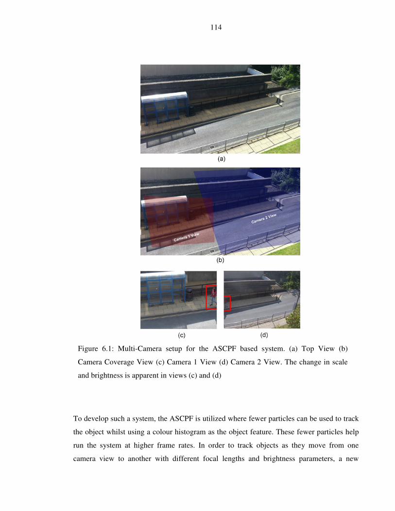
114
To develop such a system, the ASCPF is utilized where fewer particles can be used to track
the object whilst using a colour histogram as the object feature. These fewer particles help
run the system at higher frame rates. In order to track objects as they move from one
camera view to another with different focal lengths and brightness parameters, a new
Figure 6.1: Multi-Camera setup for the ASCPF based system. (a) Top View (b)
Camera Coverage View (c) Camera 1 View (d) Camera 2 View. The change in scale
and brightness is apparent in views (c) and (d)

115
approach has been followed where the scale and the colour change is compensated by
adjusting the number of active particles and particle spread value. Up to four Axis P1344
Cameras [113] were used to test the ASCPF based system (see Appendix C for camera
details). The cameras were setup keeping in mind the above mentioned criteria. Live video
feeds were obtained from these cameras and objects were tracked as they move from one
camera to another. Figure 6.1 shows the multi camera environment setup. It can be seen
that as the object moved from camera 2 to camera 1, there was an increase in the size of the
object by more than a half. Also its position and colour information in the new camera view
is changed. In order to efficiently track the object across different camera views, it is very
important that such situations are handled with minimum error. The ASCPF based
technique discussed in this chapter is used to provide solutions to these three fundamental
issues and is presented in the following Sections.
6.4 Object Position
Object position is the most significant feature when tracking objects in a multi camera
environment. As the object moves from one view to another, it is very important to get an
accurate position in the new scene. In order to obtain object position with minimum error,
all the cameras are calibrated. There are a number of techniques proposed in the literature
for tackling this problem and these can be broadly categorized as pattern based calibration
and self- or auto-calibration.
Pattern based calibration techniques are used in the proposed method. A well known pattern
based calibration technique, proposed in [114], was considered to obtain 2D image
coordinates.
Once intrinsic and extrinsic parameters were available, 2D image coordinates were
converted to 3D world coordinates and vice versa to get the exact object location in
different camera views. Fig. 6.2 shows the selected point in one view and the corresponding
point in the other camera view after applying the camera calibration technique proposed in
[114].

116
Figure 6.2:(a) selected point on Camera 1 (b) corresponding point projected in Camera 2
6.5 Scaling
The second important feature of the proposed system is the capability to cope with the
situation where the scale of the object changes as it moves into the new camera view. As
shown in Figure 6.1(c) and 6.1(d), as the object moves from one view to another, its scale
changes. The number of active particles and particle spread variables, discussed in the
previous chapter, are utilized to overcome this situation. When the object position is
obtained in the new camera views, the number of active particles along with the particle
spread value is increased to a maximum to counter not only the scale change but also any

117
error from the calibration step. This helps the proposed system identify the tracked object
with more accuracy in the new view.
Figure 6.3: Particle spread radius of the object being tracked using the proposed method.
The red circle shows the spread radius and the blue spots show the particles. The tracked
object moves from Camera 2 to Camera 1. (a) and (b) images are from Camera 2, (d) to (f)
images are from Camera 1. The frames run from right to left.
Figure 6.3 shows a series of images, where the object is tracked from Camera 2 to Camera
1 (right to left). It can be seen that as the object moves from one view to another the scale
of the object changes. To overcome this situation the number of particles and the spread
value are increased. This can be seen clearly from Figure 6.3(b) and 6.3(c) where the spread
value increases along with the number of particles as the object moves from Camera 2

118
(shown in Figure 6.3(a) and 6.3(b)) to Camera 1 (shown in Figure 6.3(c) to 6.3(f)). As the
tracking filter adapts to the new camera view, the number of particles and the spread value
are again reduced to lower the computational cost, as shown in the Camera 1 images. It can
be seen that in the first view the number of active particles is reduced to a minimum due to
accurate tracking outputs, but as the object moves into the next view the number of active
particles and also the spread value is set to a maximum.
6.6 Colour Features
Object colour was used as a feature to track the object. A reference colour histogram for
each of the tracked objects is obtained at the time when it is selected for tracking. In the
subsequent frames, the histogram for each particle is obtained and compared with this
reference histogram. A Bhattacharyya coefficient was calculated using equation (6.4) to get
the matching distance between the two histograms:
∑ =−=
U
uk uhuhD0
)(')(1
(6.4)
where U is the total number of histogram bins and )(uh and )(' uh are the current and
reference histograms, respectively.
As the object moves from one view to another, due to the change in the scale and brightness
parameters, it is important to update its reference histogram. Since with the change in
lighting conditions the distance between the reference and the current histogram will
increase, which can result in false tracking outputs, a maximum match technique is used to
update the reference histogram. As explained in the previous section, the particle spread
and number of particles are increased to overcome the scale changes, the same procedure
being followed as before. The current histogram for each of the new particles is obtained
and the Bhattacharyya coefficient is calculated. The particle with the highest weight is
obtained and the colour histogram of the highest weighted particle is then made the

119
reference histogram for the new camera view. This technique helps the ASCPF based
method to keep track of the moving object.
6.7 Experimental Results
The ASCPF based tracking method has been tested on live video feeds from up to four
Axis cameras. The overall camera setup is shown in Figure 6.1 where no two camera views
overlap by no more than 10%. Objects are tracked as they move from one view to another
in both directions. The standard deviation value for the particle spread is set to 0.6 whereas
for matching the colour histograms it is set to 0.2. The minimum and maximum number of
particles was selected according to procedures discussed in the previous chapter. The
proposed system has been tested on five progressively more complex data sequences shot
in different weather and lighting conditions where the fourth sequence involved up to four
camera views. To thoroughly evaluate the performance of the system, comparisons are also
made with standard particle filter techniques in terms of computational cost.
Figure 6.3, 6.4 and 6.5 show images from three sequences shot in different weather and
lighting conditions used to test the proposed system. Figure 6.6 and 6.7 are from a video
sequence with three and four camera views respectively. The camera configuration and
setup was slightly different in Figure 6.7 as compared to the other test sequences. The
tracked object is manually selected by a mouse click on the initial selection screen. It can
be seen that although the scene activity density, weather and lighting conditions are
different in all the sequences, the ASCPF method is able to successfully track all the
moving objects using a reduced number of particles.

120
Figure 6.4: Images from one of the test sequences where the object is tracked using the
proposed system. The frames run from right to left

121
Figure 6.5: Images from a crowded test sequence. The proposed system successfully tracks
the object even though it is surrounded by other moving objects in the scene. The frames
run from right to left

122
Figure 6.6: Images from an added view video sequence. The added camera is installed on
the left of Camera 1. The proposed system successfully tracks the object as it moves from
one view to another. The frames run from left to right

123
Figure 6.7: Images from four camera view video sequence. The added cameras are installed
on the left of Camera 2. The camera configuration is slightly different than the previous
setup. The ASCPF based tracking system successfully tracks the object as it moves from
one view to another. The frames run from right to left where the person enters the scene
from the right of Camera 1 and exits from the left of the additional Camera View 2.

124
6.8 Conclusion
A multi camera tracking system based on ASCPF has been presented in this chapter for
which the main focus is to improve the performance of the system in terms of
computational cost. Multi camera tracking environments usually pose challenges such as
change in the scale and appearance of the tracked objects as they move across different
camera views. These challenges are tackled using the ASCPF technique. A well known
camera calibration technique is used to map image coordinates from different camera views
to global world coordinates. The variable particle spread feature of ASCPF is utilized to
minimize any effects of scale change and a reference histogram update technique is
deployed to maintain object features across different cameras.
The technique has been tested on progressively complex video sequences from live camera
feeds. It has been observed that, due to the adaptive nature of the ASCPF, the ASCPF did
not only run faster than video rate but also successfully tracked the objects in all the test
sequences.

125
Chapter 7
Conclusion and Future Work

126
Chapter 7
CONCLUSIONS
AND FUTURE WORK
7.1 Conclusions
An effort has been made in this thesis to study and develop robust event detection and
object tracking techniques that can used to track different objects in complex video scenes.
Object tracking has been the focus of many studies in the past. Due to the advances in
technology in the last decade more powerful systems are now available that are not only
used to implement various computer vision techniques requiring the use of complex
mathematical models but also maintain video rate processing. These systems have allowed
engineers to design more robust and intelligent tracking systems that can be implemented
for public safety and surveillance across the world. Keeping in view the importance of the
problem, a study has been conducted and is presented in this thesis where the main focus is
to track objects in different environments and scene settings whilst maintaining their
identity.
The thesis is divided into five progressively more complex problem domains detailed in
successive individual chapters. The first chapter presents the putatively straightforward
problem of detecting an intruder entering a marked alarm zone under consistent lighting
conditions. A simple GMM based background segmentation and tracking technique is used

127
to detect and track objects as they enter the zone. The output of the GMM was used to
identify moving pixels in the scene. These pixels are then classified as objects based on
their width and height. Alarm events are generated if these objects are found within the
marked zone for longer than a certain period of time. Potential false alarms can be
generated by small animals entering the zone and poor weather conditions such as sleet
falling past the camera. Intruders approach the fence in several different ways such as by
walking, crawling and rolling, and each of these must be classified. In addition, the
lighting conditions vary with some scenes being shot at night under artificial near infra-red
illumination.
The chapter highlights the main issues faced by the surveillance systems when
implemented in outdoor environments. It is observed that, although the GMM copes well
with a gradual lighting change, its performance is compromised as soon as there is a sudden
change in scene illumination. Another observation is made regarding the number of moving
objects in the scene. Since no unique object identification technique is applied, the system
fails to keep track of the object identity if two or more objects cross each other. Although
the proposed method is able to achieve over 90% detection success rate when tested on
over 24 hours worth of video sequences with consistent lighting, it fails in more complex
situations where the lighting was inconsistent or there are multiple objects in the scene.
More robust solutions are presented in the subsequent chapters where edge and colour
information is utilised to keep track of the objects in contrast to simple pixel tracking
techniques.
Chapter 3 and 4 discuss techniques used to track objects in variable lighting conditions. In
both chapters edges are used as the main features to keep track of the objects. Since edges
are less sensitive to illumination change, it makes them a favourable feature for tracking.
However, on the other hand edges are also very sensitive to motion of the object. Any
change in the object motion can cause the edge map to change which can result in false
tracking outputs. Keeping in view these limitations only those objects are considered for
tracking which become stationary in the scene. Objects such as baggage unattended in
public places or vehicles parked illegally on the road side are examples of such situations.
Since these objects can pose a serious security threat, their identification and tracking is an
important part of any video surveillance application.

128
Magnitude of edge is used in Chapter 3 mainly in indoor environments to track objects that
become stationary in the scene. GMM is initially used to segment moving objects. These
objects are then identified as stationary using a Centroid-Range method. The Centroid-
Range method requires an isolated view of the objects before identifying them as stationary
and thus does not handle any occlusion. Edge maps for the identified objects are obtained
using the well known Canny edge detector and stored as templates. The correlation
technique is applied to match the stored templates with the edge maps obtained from the
area encompassed by the stationary objects from the current frame. The technique is tested
on seven different indoor sequences with relatively consistent lighting and achieves 100%
success rate.
However, when the same technique was tested in an outdoor environment the success rate
came down to around 57%. It is observed from the overall results that there are two major
issue that the method fails to address: 1) an isolated view of the object is required before
identifying it as stationary. This requirement is typically difficult to meet, especially in
crowded scenes where stationary objects might be frequently occluded; 2) though
magnitude of edge can perform better than techniques based on colour features in
inconsistent lighting conditions, its performance is compromised when lighting variations
are higher than a certain level. To address these issues, a more robust object detection and
tracking system is studied in the subsequent chapter that can track objects in both indoor
and outdoor environments with variable lighting conditions.
In order to develop more robust object detection and tracking system, a pixel based
classification model is used in Chapter 4. The proposed detection model not only picks up
stationary objects accurately in changing lighting conditions but also handles occlusion.
These stationary objects are then tracked using a novel adaptive edge orientation based
technique where orientation of the edge is exploited instead of magnitude to keep track of
the stationary object. Experimental results have shown that the discussed technique gives
more than a 95% detection success rate in both indoor and outdoor environments, even if
objects are partially occluded. The technique is tested on several hours of video sequences
recorded at different locations and times of day. The results obtained are compared with the
other available state-of-the-art methods. Experiment results show that the proposed method

129
significantly improves the performance of the system as compared to the other techniques
available in the literature and the one presented in Chapter 3.
As is apparent from the work of Chapter 3 and 4, edge information is sensitive to the
motion of the object so methods based on this are usually only used to locate stationary
objects with consistent edge features. In order to track non-rigid moving objects such as
humans in crowded scenes, edges are usually not a practical attribute and colour features
are exploited in such situations. Particle filtering techniques have been used extensively
over the past few years in this regard. Due to the nonlinear nature of the particle filter and
the fact that it does not assume a Gaussian probability density, it tends to outperform other
available tracking methods.
A novel adaptive sample count particle filter (ASCPF) tracking method is presented in
Chapter 5 for which the main motivation is to accurately track an object in crowded scenes
using fewer particles and hence with reduced computational overhead. Instead of taking a
fixed number of particles, a particle range technique is used where an upper and lower
bound for the range is initially identified. Particles are made to switch between an active
and inactive state within this identified range. The idea is to keep the number of active
particles to a minimum and only to increase this as and when required. This, together with
the variable particle spread, allows a more accurate proposal distribution to be generated
while using less computational resource.
The proposed ASCPF method has been evaluated on different real life complex scenarios.
The test sequences were selected keeping in mind real life situations such as occlusion,
scale changes and variable target motion. Different experiments have shown that, although
using the adaptive sampling approach alone reduces the computational cost, it nevertheless
looses tracking accuracy when the object is frequently occluded. A variable particle spread
approach is introduced to ameliorate such situations. Experimental results show that the
proposed method tracks the object with slightly less accuracy to existing particle filter
techniques but is up to five times faster.
The ASCPF technique presented in Chapter 5 has been implemented in a multi-camera
environment to track an object across different scenes. Since the technique provided a real
time solution to track objects in crowded scenes, it was decided to evaluate its performance
in a more complex environment. Multi-camera environments can pose difficult challenges

130
such as the absolute requirement for video rate tracking, change in the scale of the object as
it moves from one camera to another or a change in object features, such as colour, since
the brightness levels can alter across different camera views. Different ASCPF features are
used to overcome each of these challenges. Adaptive samples allowed the ASCPF
technique to track an object at video rate. Since fewer particles are used to track the object
using the ASCPF technique, fewer resources are required. A variable standard deviation
value of the ASCPF is utilized in order to cope with sudden colour and scale changes. As
the object moves from one scene to another, the number of particles, along with their
spread value, is increased to a maximum to reduce any effects of scale and colour change. It
was found that not only did the ASCPF method result in successfully tracking the moving
object across different views but it also maintained the real time frame rate due to its
reduced computational cost. The ASCPF thus may provide a practical solution for tracking
objects in multi-camera environments.
7.2 Future Work
The techniques presented in this thesis can further be improved to try and obtain a fuller
scene understanding. The edge based tracking techniques successfully detect and track
objects that become stationary in the scene. Although they achieved over 95% detection
success rate, there are certain situations where change in lighting can cause false areas to be
picked up as stationary objects. Since no object classification is deployed to distinguish
between a legitimate stationary object and a false foreground region, a correlation based
technique can be applied to ensure that only legitimate objects such as vehicles or baggage
are picked up for alarm events. The implementation of such methods might require more
computing power since any decisions based on the outcome are required to be made at run
time or certainly within seconds. Though such a system might not be available at the time
this study has been conducted it could be a step in the right direction.
Establishing the relationship between objects (both moving and stationary) in the scene is
another important step towards full scene understanding. Activity recognition has been the
focus of many studies in the past and similar techniques will be useful for possible

131
implementation in the unconstrained environments considered in this study. The work
conducted as part of this thesis only focuses on detection of stationary objects. There is no
method applied to identify if stationary objects have been left unattended or not by an
associated supervisory agent. Since unattended baggage or vehicles can cause a serious
threat, establishing association between them and other moving objects in the scene can
give useful information. For example identifying owner(s) of the luggage left in a public
place or of a vehicle parked illegally can be of great importance as this could prevent a
serious security threat. Facial recognition techniques can be implemented on high
resolution images to identify potential criminals in this regard.
Within the work developed for tracking objects in crowded scenes, despite the encouraging
results, there is still much scope for further improvement. The ASCPF technique presented
in the thesis works primarily on colour based histogram matching. A problem arises when
multiple objects of similar colour make contact with each other. Although the system on
most occasions keeps track of the original object, there are still situations where the track is
either lost or handed over to the co-located object. A multi-track particle filter could be
implemented to solve this problem. Based on the distribution of the particles, the object
track can be split into two or more tracks if such situations are encountered. The posterior
distribution can be divided into small weighted clusters. If the distance between each
cluster is greater than a certain threshold, the track can be split into multiple branches.
Similarly, if two or more tracks tend to converge into a single track, the distance threshold
can again be used to merge multiple tracks back into a single track. This can help the
ASCPF to keep track of multiple objects with similar colour features. Another way of
solving this problem would be to increase the particle filter dimensions to cover features
other than colour so they can be considered for matching. Through this route it may be
possible solve the issue at hand but it will of course require more computation resources.
ASCPF implementation in a multi camera environment is another important feature of this
study.
While the ASCPF solution provided encouraging results, there is much room for
improvement. The reference histogram update mechanism can further be refined by a more
sophisticated approach than the one currently being used. This could help improve the
histogram matching results in the new camera view. Another important aspect of the

132
problem is in the setting up of the multi-camera environment. This is currently setup
manually and cameras are calibrated using known world coordinates and their
corresponding image coordinates. Any change in camera position (zoom, pan or tilt) results
in a requirement for recalibration of that particular camera. This would ideally be replaced
by self- or auto- calibration techniques but which will, again, require more computational
resources.
133
References
[1] VSAM “Visual Surveillance and Monitoring”, Available at http://www-
2.cs.cmu.edu/~vsam/ Date of access: 23-04-11
[2] Safer Caerphilly Community Safety Partnership website
http://www.caerphilly.gov.uk Date of access: 15-07-2011
[3] M. W. Green, “The Appropriate and Effective Use of Security Technologies in U.S.
Schools”, A Guide for Schools and Law Enforcement Agencies, Sandia National
Laboratories, September 1999, NCJ 178265
[4] i-LIDS dataset, United Kingdom Home Office dataset. Available at
http://www.homeoffice.gov.uk/science-research/hosdb/i-LIDS/ Date of access: 01-
06-2010
[5] MIT Traffic dataset, Available at
http://www.ee.cuhk.edu.hk/~xgwang/MITtraffic.html Date of access: 18-06-11
[6] ViSOR dataset, Available at http://imagelab.ing.unimore.it/visor/ Date of access:
18-06-11
[7] PETS 2006 dataset, Available at
http://www.cvg.cs.reading.ac.uk/PETS2006/data.html Date of access: 18-06-11
[8] University of Sussex Traffic dataset, Available at http://www.sussex.ac.uk/iims/
Date of access: 28-11-11
[9] University of Sussex Tracking dataset, Available at http://www.sussex.ac.uk/iims/
Date of access: 28-11-11
[10] ABI research report “The Video Surveillance Market Hardware and Software
Market Trends and Forecasts”, 2010.
[11] IBM “Business Analytics for Retail”, available on website http://www-
01.ibm.com/software/analytics/retail/ Date of access: 09-10-11
[12] NICE Systems Ltd website http://www.nice.com/video Date of access: 09-10-11
[13] The National Center for Education Statistics (NCES) and Institute of Education
Sciences (IES) report “Indicators of School Crime and Safety: 2010” available at
http://nces.ed.gov Date of access: 09-10-11

134
[14] M. Valera, S. A. Velastin, A. Ellis, J. Ferryman, "Communication Mechanisms and
Middleware for Distributed Video Surveillance," IEEE Transactions on Circuits
and Systems for Video Technology,vol.21, no.12, pp.1795-1809, 2011
[15] C. Beleznai, B. Fruhstuck, and H. Bischof, “Human detection in groups using a fast
mean shift procedure,” International Conference on Image Processing, pp. 349–
352, 2004
[16] H. Elzein, S. Lakshmanan, and P. Watta, “A motion and shapebased pedestrian
detection algorithm,” IEEE Intelligent Vehicles Symposium, pp. 500–504, 2003
[17] D. J. Lee, P. Zhan, A. Thomas, and R. Schoenberger, “Shape-based human intrusion
detection,” SPIE International Symposium on Defense and Security, Visual
Information Processing XIII, 5438: pp. 81–91, 2004
[18] Jianpeng Zhou and Jack Hoang, “Real time robust human detection and tracking
system”, IEEE Computer Society Conference on Computer Vision and Pattern
Recognition, vol. 3: pp. 149 – 149, 2005
[19] D.M. Gavrila, “A Bayesian Exemplar-Based Approach to Hierarchical Shape
Matching,” IEEE Trans. Pattern Analysis and Machine Intelligence, vol. 29, no. 8,
pp. 1408-1421, Aug. 2007.
[20] D.M. Gavrila and S. Munder, “Multi-Cue Pedestrian Detection and Tracking from a
Moving Vehicle,” International Journal of Computer Vision, vol. 73, no. 1, pp. 41-
59, 2007
[21] B. Stenger, A. Thayananthan, P.H.S. Torr, and R. Cipolla, “ModelBased Hand
Tracking Using a Hierarchical Bayesian Filter,” IEEE Trans. Pattern Analysis and
Machine Intelligence, vol. 28, no. 9, pp. 1372-1385, 2006
[22] K. Toyama and A. Blake, “Probabilistic Tracking with Exemplars in a Metric
Space,” International Journal of Computer Vision, vol. 48, no. 1, pp. 9-19, 2002
[23] C. Papageorgiou and T. Poggio, “A Trainable System for Object Detection,”
International Journal of Computer Vision, vol. 38, pp. 15-33, 2000
[24] A. Mohan, C. Papageorgiou, and T. Poggio, “Example-Based Object Detection in
Images by Components,” IEEE Transaction on Pattern Analysis and Machine
Intelligence, vol. 23, no. 4, pp. 349-361, 2001

135
[25] P. Viola, M. Jones, and D. Snow, “Detecting Pedestrians Using Patterns of Motion
and Appearance,” International Journal of Computer Vision, vol. 63, no. 2, pp. 153-
161, 2005
[26] N. Buch, S.A. Velastin, J. Orwell,"A Review of Computer Vision Techniques for
the Analysis of Urban Traffic," IEEE Transactions onIntelligent Transportation
Systems, vol.12, no.3, pp.920-939, 2011
[27] C. Stauffer and W.E.L. Grimson, “Adaptive background mixture models for real-
time tracking,” IEEE Computer Society Conference on Computer Vision and
Pattern Recognition, pp. 2, 1999
[28] Fatih Porikli, Yuri Ivanov and Tetsuji Haga, “Robust Abandoned Object Detection
Using Dual Foregrounds,” EURASIP Journal on Advances in Signal Processing,
vol. 2008, pp. 1-10, 2008
[29] V. Reddy, C. Sanderson and B.C. Lovell, “Robust Foreground Object Segmentation
via Adaptive Region-Based Background Modelling,” 20th International Conference
on Pattern Recognition (ICPR), pp. 3939-3942, 2010
[30] C. Zhao, X. Wang, W. Cham, "Background Subtraction via Robust Dictionary
Learning," EURASIP Journal on Image and Video Processing, Volume 2011 ,
Article ID 972961, 2011
[31] Lu Wang and N.H.C. Yung, “Extraction of Moving Objects From Their
Background Based on Multiple Adaptive Thresholds and Boundary Evaluation,”
IEEE Transactions on Intelligent Transportation Systems, vol.11, no.1, pp. 40-51,
2010
[32] K. Srinivasan, K. Porkumaran and G. Sainarayanan, “Improved background
subtraction techniques for security in video applications,” 3rd International
Conference on Anti-counterfeiting, Security, and Identification in Communication,
pp. 114-117, 2009
[33] Y. Tian, R. S. Feris and A. Hampapur, “Real-time detection of abandoned and
removed objects in complex environments,” IEEE Int. Workshop Visual
Surveillance, 2008
[34] Y. Tian, R. Feris, H. Liu, A. Hampapur and M. Sun, “Robust Detection of
Abandoned and Removed Objects in Complex Surveillance Videos,” IEEE

136
Transactions on Systems, Man, and Cybernetics, Part C: Applications and Reviews,
vol.41, no.5, pp. 565-576, 2011
[35] P.L. Venetianer, Z. Zhang, W. Yin and A.J. Lipton, “Stationary target detection
using the objectvideo surveillance system,” IEEE Conference on Advanced Video
and Signal Based Surveillance, pp. 242-247, 2007
[36] F. Ren, J. Huang, R. Jiang, R. Klette, “General traffic sign recognition by feature
matching,” 24th International Conference Image and Vision Computing New
Zealand, 2009
[37] Y. Yang, C. Yang; X. Wang. “A Detection and Tracing Algorithm of Moving
Vehicles,” 2nd International Conference on Pervasive Computing and Applications,
2007
[38] S. H. Jeon, K. Lee, B. Kwon, “Application of template matching method to traffic
feature detection using KOMPSAT EOC imagery,” IEEE International Geoscience
and Remote Sensing Symposium, 2005
[39] N. Buch, J. Orwell, S.A. Velastin,"Urban road user detection and classification
using 3D wire frame models," IET Computer Vision, vol.4, no.2, pp.105-116, 2010
[40] S. Ferrando, G. Gera, M. Massa amd C. Regazzoni, “A New Method for Real Time
Abandoned Object Detection and Owner Tracking,” IEEE International Conference
on Image Processing, pp. 3329-3332, 2006
[41] Yiping Tang, Feihu Hu, Guanbao Yang and Bei Lin, “Property protection system
based on Omni-Directional Vision Sensors,” 3rd International Congress on Image
and Signal Processing (CISP), pp. 181-184, 2010
[42] Jianting Wen, Haifeng Gong, Xia Zhang and Wenze Hu, “Generative model for
abandoned object detection,” 16th IEEE International Conference on Image
Processing (ICIP), pp. 853-856, 2009
[43] Xuli Li, Chao Zhang, and Duo Zhang, “Abandoned Objects Detection Using
Double Illumination Invariant Foreground Masks,” 20th International Conference
on Pattern Recognition (ICPR), pp. 436-439, 2010
[44] Y. Satoh, S. Kaneko, Y. Niwa and K. Yamamoto, “Robust object detection using a
radial reach filter(rrf),” Systems and Computers in Japan, vol. 35, no. 10, pp. 63–73,
2004

137
[45] Qiujie Li, Yaobin Mao, Zhiquan Wang and Wenbo Xiang, “Robust Real-Time
Detection of Abandoned and Removed Objects,” Fifth International Conference on
Image and Graphics, pp. 156-161, 2009
[46] Tang Yi Ping and Chen Yao Yu, “Illegally Parked Vehicles Detection Based on
Omnidirectional Computer Vision,” 2nd International Congress on Image and
Signal Processing, pp. 1-5, 2009
[47] R. H. Evangelio, T. Sikora, "Static Object Detection Based on a Dual Background
Model and a Finite-State Machine," EURASIP Journal on Image and Video
Processing, Volume 2011 , Article ID 858502, 2011
[48] Jong Taek Lee, M.S. Ryoo, M. Riley and J.K. Aggarwal, “Real-time detection of
illegally parked vehicles using 1-D transformation,” IEEE Conference on Advanced
Video and Signal Based Surveillance, pp. 254-259, 2007
[49] J.T. Lee, M.S. Ryoo, M. Riley and J.K. Aggarwal, “Real-Time Illegal Parking
Detection in Outdoor Environments Using 1-D Transformation,” IEEE
Transactions on Circuits and Systems for Video Technology, vol.19, no.7, pp. 1014-
1024, 2009
[50] A. Bevilacqua and S. Vaccari, “Real time detection of stopped vehicles in traffic
scenes,” IEEE Conference on Advanced Video and Signal Based Surveillance, pp.
266-270, 2007
[51] S. Boragno, B. Boghossian, J. Black, D. Makris and S. Velastin, “A DSP-based
system for the detection of vehicles parked in prohibited areas,” IEEE Conference
on Advanced Video and Signal Based Surveillance, pp. 260-265, 2007
[52] S. Guler, J.A. Silverstein and I.H. Pushee, “Stationary objects in multiple object
tracking,” IEEE Conference on Advanced Video and Signal Based Surveillance, pp.
248-253, 2007
[53] Jing-Ying Chang, Huei-Hung Liao and Liang-Gee Chen, “Localized Detection of
Abandoned Luggage,” EURASIP Journal on Advances in Signal Processing, vol.
2010, Article ID 675784, 9 pages, 2010
[54] F. Lv, X. Song, B. Wu, V. K. Singh and R. Nevatia, “Left luggage detection using
bayesian inference,” 9th IEEE International Workshop on Performance Evaluation
in Tracking and Surveillance (PETS '06), pp. 83-90, 2006

138
[55] E. Auvinet, E. Grossmann, C. Rougier, M. Dahmane and J. Meunier, “Left-luggage
detection using homographies and simple heuristics,” IEEE International Workshop
on PETS, pp. 51–58, 2006
[56] M. Piccardi and E.D. Cheng, “Multi-Frame Moving Object Track Matching Based
on an Incremental Major Color Spectrum Histogram Matching Algorithm,” IEEE
Computer Society Conference on Computer Vision and Pattern Recognition -
Workshops, pp. 19-19, 2005
[57] S.M. Khan and M. Shah, “Tracking Multiple Occluding People by Localizing on
Multiple Scene Planes, IEEE Transactions on Pattern Analysis and Machine
Intelligence, vol.31, no.3, pp. 505-519, 2009
[58] F. Jialue, X. Wei, W. Ying, G. Yihong, “Human Tracking Using Convolutional
Neural Networks,” IEEE Transactions on Neural Networks, vol.21, no.10, pp.1610-
1623, 2010
[59] J. Berclaz, F. Fleuret, E. Türetken, Pascal Fua, “Multiple Object Tracking Using K-
Shortest Paths Optimization,” IEEE Transactions on Pattern Analysis and Machine
Intelligence, vol. 33, no. 9, pp. 1806-1819, 2011
[60] H. Kjellstrom, D. Kragic, M. J. Black, “Tracking people interacting with objects,”
IEEE Computer Society Conference on Computer Vision and Pattern Recognition,
pp. 747-754, 2010
[61] E. L. Andrade, J. C. Woods, E. Khan, M. Ghanbari, “Region-based analysis and
retrieval for tracking of semantic objects and provision of augmented information in
interactive sport scenes,” IEEE Transactions on Multimedia, vol. 7, no. 6, pp. 1084-
1096, 2005
[62] V. A. Prisacariu, I. D. Reid, "PWP3D: Real-Time Segmentation and Tracking of 3D
Objects," International Journal of Computer Vision, pp. 1-20, 2012
[63] W. Fan-Tung, C. Sheng-Ting, L. Chia-Wen, A region-based object tracking scheme
using Adaboos-based feature selection, IEEE International Symposium on Circuits
and Systems, ISCAS 2008, pp. 2753-2756, 2008
[64] Z. Kalal, K. Mikolajczyk, J. Matas, "Tracking-Learning-Detection," IEEE
Transactions on Pattern Analysis and Machine Intelligence, vol.PP, no.99, pp.1,
2011

139
[65] D. Marimon, T. Ebrahimi, “Orientation histogram-based matching for region
tracking,” Eighth International Workshop on Image Analysis for Multimedia
Interactive Services, pp.8, 2007
[66] Michael Kass, Andrew Witkin, Demetri Terzopoulos, “Snakes: Active Contour,”
Models, International Journal of Computer Vision, vol 1, pp. 321-331, 1998
[67] Chenyang Xu, Jerry L. Prince, “Snakes, Shapes, and Gradient Vector flow,” IEEE
Transactions on Image processing, vol.7, no 3, pp. 359-369, 1998
[68] D.J. Williams, M. Shah, “A fast algorithm for active contours,” Third International
conference on Computer Vision, pp. 592-595, 1990
[69] N. Bangalore, R.C.D. Young, P.M. Birch, C.R. Chatwin, “Tracking Moving Objects
Using Bandpass Filter Enhanced Localisation and Automated Initialisation of
Active Contour Snakes,” ICGST International Journal on Graphics, Vision and
Image Processing, GVIP, vol. 10, pp. 1-8, 2010
[70] S. Lefevre, J.G. Gerard, A. Piron, N. Vincent, “An Extended Snake model for Real-
time multiple Object tracking,” International workshop on Advanced concepts for
Intelligent vision systems, pp.268-275, 2002
[71] T. Chan, L. Vese, “Active contour without edges,” IEEE transactions on Image
processing, vol.10, no.2, pp. 266-277, 2001
[72] Min Hu, Xijian Ping, Yihong Ding, “Automated Cell Nucleus Segmentation using
Improved Snake,” International Conference on Image Processing, Volume 4, pp.
2737–2740, 2004
[73] C. Madden, E. Cheng, M. Piccardi, “Tracking people across disjoint camera views
by an illumination-tolerant appearance representation,” Machine Vision and
Applications, vol. 18, no. 3, pp. 233–247, 2007
[74] Jianbo Shi, Carlo Tomasi, Good Features to Track, IEEE Conference on Computer
Vision and Pattern Recognition, pp. 593-600., 1994
[75] B. Benfold, I. Reid, "Stable multi-target tracking in real-time surveillance video,"
IEEE Conference on Computer Vision and Pattern Recognition (CVPR), pp.3457-
3464, 2011
[76] Miroslav Trajkovic, Mark Hedley, “Fast corner detection,” Image and Vision
Computing, vol 16, issue 2, pp. 75-87, 1998

140
[77] David G. Lowe, “Object recognition from local Scale-Invariant features,” Seventh
international conference on Computer Vision (ICCV 99), vol 2, pp.1150, 1999
[78] G.I. Chiou, Jenq-Neng Hwang, “A neural network-based stochastic active contour
model (NNS-SNAKE) for contour finding of distinct features,” IEEE Transactions
on Image Processing, vol.4, no.10, pp. 1407-1416, 1995
[79] M. Gastaud, M. Barlaud, G. Aubert, “Combining shape prior and statistical features
for active contour segmentation,” IEEE Transactions on Circuits and Systems for
Video Technology, vol.14, no.5, pp. 726- 734, 2004
[80] O. Michailovich, Y. Rathi, A. Tannenbaum, “Image Segmentation Using Active
Contours Driven by the Bhattacharyya Gradient Flow,” IEEE Transactions on
Image Processing, vol.16, no.11, pp. 2787-2801, 2007
[81] K. Somkantha, N. Theera-Umpon, S. Auephanwiriyakul, “Boundary Detection in
Medical Images Using Edge Following Algorithm Based on Intensity Gradient and
Texture Gradient Features,” IEEE Transactions on Biomedical Engineering, vol.58,
no.3, pp. 567-573, 2011
[82] S. Sun, D. R. Haynor, Y. Kim, “Semiautomatic video object segmentation using
VSnakes,” IEEE Transactions on Circuits and Systems for Video Technology, vol.
13, no. 1, pp. 75–82, 2003
[83] Q. Chen, Q. S. Sun, P. A. Heng, D. S. Xia, “Parametric active contours for object
tracking based on matching degree image of object contour points,” Pattern
Recognition Letters, vol. 29, no. 2, pp.126–141, 2008
[84] N. Paragios, R. Deriche, Geodesic active regions for motion estimation and
tracking, Seventh IEEE International Conference on Computer Vision, 1999., vol.1,
pp. 688-694, 1999
[85] D. Chun-li, D. Yu-ning, A Novel Algorithm for Object Tracking with Particle
Filtering and GVF-Snake, Eighth International Conference on Intelligent Systems
Design and Applications, 2008, vol.2, pp. 8-13, 2008
[86] A. Aksel, S.T. Acton, “Target tracking using the snake particle filter,” IEEE
Southwest Symposium on Image Analysis & Interpretatio, pp. 33-36, 2010
141
[87] Y. Rathi, N. Vaswani, A.Tannenbaum, A. Yezzi, “Tracking Deforming Objects
Using Particle Filtering for Geometric Active Contours,” IEEE Transactions on
Pattern Analysis and Machine Intelligence, vol. 29, pp. 1470-1475, 2007
[88] N. T. Nguyen, S. Venkatesh, G. West, and H. H. Bui, “Multiple camera
coordination in a surveillance system,” ACTA Automatica Sinica, vol. 29, no. 3, pp.
408-421, 2003
[89] O. Javed, Z. Rasheed, K. Shafique, and M. Shah, “Tracking across multiple cameras
with disjoint views,” IEEE International Conference on Computer Vision, vol. 1,
pp.952-957, 2003
[90] R. O. Duda, P. E. Hart, and D. G. Stork, “Pattern Classification,” Wiley-
Interscience, 2nd edition, pp. 164-173, 2000
[91] J. Ren, M. Xu, J. Orwell, G.A. Jones, Graeme A., "Multi-camera video surveillance
for real-time analysis and reconstruction of soccer games," Machine Vision and
Applications, vol. 21(6), pp. 855-863, 2010
[92] J. Black and T. Ellis, “Multi-camera image tracking,” Image and Vision Computing,
vol. 24(11), pp. 1256–1267, 2006
[93] Liu Li, Sun Bo, Wei Ning, Chao Hu, M.Q.H. Meng, ”A Novel Marker Tracking
Method Based on Extended Kalman Filter for Multi-Camera Optical Tracking
Systems,” 5th International Conference on Bioinformatics and Biomedical
Engineering, (iCBBE) 2011, pp.1-5,2011
[94] F. Fleuret, J. Berclaz, R. Lengagne, and P. Fua, “Multi-camera people tracking with
a probabilistic occupancy map,” IEEE Transactions on Pattern Analysis and
Machine Intelligence, vol.30, no.2, pp.267-282, 2008
[95] R. Mohedano and N. Garcia, “Robust multi-camera tracking from schematic
descriptions,” 17th IEEE International Conference on Image Processing (ICIP),
pp.3949-3952, 2010
[96] Yifan Zhou, J. Benois-Pineau, and H. Nicolas, “A multi-resolution particle filter
tracking with a dual consistency check for model update in a multi-camera
environment,” 11th International Workshop on Image Analysis for Multimedia
Interactive Services (WIAMIS), pp.1-4, 2010

142
[97] R. Mohedano and N. Garcia, “Robust multi-camera 3D tracking from mono-camera
2d tracking using Bayesian Association,” IEEE Transactions on Consumer
Electronics,vol.56, no.1, pp.1-8, 2010
[98] K. Kim and L.S. Davis, “Multi-camera tracking and segmentation of occluded
people on ground plane using search guided particle filtering,” European
Conference on Computer Vision, pp. 98-109, 2006
[99] G. D. Finlayson and S. D. Hordley, "Color constancy at a pixel," Journal of the
Optical Society of America A: Optics, Image Science, and Vision, vol. 18, issue 2,
pp. 253-264 2001
[100] J. Canny, “A Computational Approach to Edge Detection,” IEEE Transactions on
Pattern Analysis and Machine Intelligence, vol.PAMI-8, no.6, pp.679-698, 1986
[101] M. Roushdy, “Comparative Study of Edge Detection Algorithms Applying on the
Grayscale Noisy Image Using Morphological Filter”, ICGST International Journal
on Graphics, Vision and Image Processing, Volume 6, Issue 4, 2006
[102] M. Juneja and P. S. Sandhu, “Performance Evaluation of Edge Detection
Techniques for Images in Spatial Domain,” International Journal of Computer
Theory and Engineering, vol. 1, No. 5, 2009
[103] i-LIDS Team, “Imagery Library for Intelligent Detection Systems (i-LIDS); A
Standard for Testing Video Based Detection Systems,” 40th Annual IEEE
International Carnahan Conferences Security Technology, pp.75-80, 2006
[104] A. Dearden and Y. Demiris, “Tracking football player movement from a single
moving camera using particle filters,” 3rd European Conference on Visual Media
Production, pp. 29–37, 2006
[105] X. Xinyu and L. Baoxin, “Adaptive Rao–Blackwellized Particle Filter and Its
Evaluation for Tracking in Surveillance,” IEEE Transactions on Image Processing,
vol.16, no.3, pp. 838-849, 2007
[106] Xu Linzhou, Zhang Xin-hua, Yang Shao-qing and Fan Wen-tao, “An efficient
particle filter with variable number of particles for bearings-only tracking,” IEEE
10th International Conference on Signal Processing (ICSP), pp. 2395-2398, 2010
[107] D. Fox, “KLD-Sampling: Adaptive Particle Filters,” In Advances in Neural
Information Processing Systems, vol. 14, pp. 713–720, 2001

143
[108] A. Soto, “Self adaptive particle filter,” International Joint Conference on Artificial
Intelligence, pp. 1398–140, 2005
[109] D. Comaniciu, V. Ramesh and P. Meer, “Real-time tracking of non-rigid objects
using mean shift,” IEEE Conference on Computer Vision Pattern Recognition, pp.
142–149, 2000
[110] M. Taj and A. Cavallaro, “Multi-camera track-before-detect,” ACM/IEEE
International Conference on Distributed Smart Cameras, 2009.
[111] A. Sundaresan and R. Chellappa, "Multi-camera tracking of articulated human
motion using motion and shape cues," IEEE Transactions on Image Processing,
vol. 18, issue 9, pp. 2114--2126, 2009.
[112] V. I. Morariu and O. I. Camps, "Modeling correspondences for multi-camera
tracking using nonlinear manifold learning and target dynamics," Computer Vision
and Pattern Recognition, vol. 1, pages 545–552, 2006.
[113] The Axis website. [Online]. Available: http://www.axis.com
[114] J. Heikkila, “Geometric camera calibration using circular control points,” IEEE
Transactions on Pattern Analysis and Machine Intelligence, vol. 22, issue. 10, pp.
1066-1077, 2000
[115] A. Bhattacharyya, “On a measure of divergence between two statistical populations
defined by their probability distributions,” Bulletin of the Calcutta Mathematical
Society 35, pp. 99–109.

144
APPENDIX A
Gaussian Mixture Model (GMM)
The foreground/background pixel segmentation is formed using a GMM on a per pixel
basis with K Gaussian distributions for each pixel. Each Gaussian distribution has a mean
µ, a standard deviation σ and a weight ω. The robustness of the segmentation is dependent
on the value of K. If it is kept large, segmentation results improve but at the cost of slow
system performance. It has been observed that three to five Gaussians provide sufficiently
robust segmentation, whilst still maintaining real-time performance.
At a given time t, the Gaussian probability density function, G, for the kth
Gaussian
distribution, with covariance Σk,t and a mean µ is given as:
)()(2
1
,
,,
,1,,
2
1),,(
tkttkT
tkt xx
tk
tktkt exGµµ
πµ
−∑−− −
∑=∑ (A.1)
Therefore the probability that the pixel xt belongs to this Gaussian distribution is given as:
∑=
∑×=K
k
tktkttkt xGxP1
,,, ),,()( µω (A.2)
where ωk,t is an estimate of the weight of the ith
Gaussian initialized as 1/K. The weight on
each distribution represents the probability that the colour of the image pixel remains the
same, i.e. is part of the background.
A three step matching, update and decision is carried out for each pixel. A pixel is
considered to part of the background model if its value appears inside a confidence interval
of 2.5 standard deviations from the mean. If this is the case then the corresponding
distribution is updated using the following three equations:

145
ttktk xαµαµ +−= −1,, )1( (A.3)
ttktk xασασ +−= 2
,
2
, )1( (A.4)
ttktk xαωαω +−= −1,, )1( (A.5)
α here is a learning rate and plays an important role in the over all detection. A higher α
value will adapt quickly to global illumination change where as a low α value is useful for
the detection of slow moving objects. The importance of this learning rate and its effects on
real time surveillance systems is further highlighted in the results section.
Next a decision is made as to whether the new pixel value is foreground or background.
This is achieved using equation A.2 to compute the probability that a given pixel intensity
is background. The background models are classified with respect to their weights and a
thresholding mechanism is used identify if a pixel belongs to the background or
foreground. GMM relies on the assumption that the background is visible more frequently
than any foreground region. If a certain pixel value occurs repeatedly, the weight of the
corresponding model is increased and the pixel is considered to be part of the background.
If no match is found, the Gaussian distribution with the lowest weight is replaced by a new
one with the value of the pixel as the mean and with a initially high standard deviation, 0σ ,
and a low weight, 0ω . The matched distributions are then updated by calculating a new
mean, µ , and variance 2σ .
Canny Edge Detector
Canny is a multi-stage process in which the image is initially smoothed using 1D Gaussian
convolution both in the x and y direction.
),(),(),( nmfnmGnmg ∗= σ (A.6)

146
where
+−=
2
22
2 2exp
2
1
σπσσ
nmG (A.7)
It then finds the image gradient in both x and y direction using the Sobel-operator to
highlight changes in intensity, which indicates the presence of edges.
),(),(),( 22nmgnmgnmM nm += (A.8)
and
[ ]),(/),(tan),( 1nmgnmgnm mn
−=θ (A.9)
where ),(2
nmgm is the gradient in the x direction and ),(2
nmg n is the gradient in the y
direction obtained after applying the Sobel-operator.
Since edges will occur at points where the gradient is at a maximum, the algorithm then
tracks along these regions and suppresses any pixel that is not at the maximum, a process
known as non-maximal suppression.
After the non-maximum suppression step the remaining edge-pixels are labelled as strong
or weak based on their strength. Although the majority of these will probably be true edges,
some may be caused due to the presence of noise or colour variations. Thresholding is the
simplest technique used to identify true edges in which only those edges are preserved that
are stronger then a certain value. The Canny edge detection algorithm classifies these edges
into two categories, strong and weak, by using double thresholding. A high and a low
threshold value is selected. Edge-pixels stronger than the high threshold are labelled as
strong; edge pixels weaker than the low threshold are removed where as edge-pixels
between the two thresholds are marked as weak. Strong edges are considered as certain
edges and are included in the final output where as pixels marked as weak are included if
and only if they are connected to the strong edge-pixel.

147
APPENDIX B
Nonlinear Bayesian Tracking
Tracking can be defined as a process of evolving state sequence kx given by equation:
11 −− += kkk vFxx (B.1)
where F is possibly a nonlinear function of the state 1−kx and 1−kv is the process noise.
The main objective here is to recursively estimate kx given the measurement
kkk nhxz += (B.2)
where h is possibly a nonlinear function and kn is the measurement noise.
From a Bayesian point of view, tracking is the recursive estimation of kx with some degree
of confidence at time ‘k’ given the measurements kz :1 up to time k. Thus, it is requires to
construct a probability density function )( :1 kk zxp . Since it is assumed that the prior
)( 00 zxp is available, the required pdf )( :1 kk zxp is recursively obtained from a two step
prediction and update model.
If the required pdf )( 11 −− kk zxp is available at 1−k , the prior pdf of the state at time k is
obtained using equation
11111 )()()( −−−−− ∫= kkkkkkk dxzxpxxpzxp (B.3)

148
where )( 11 −− kk zxp is the previous a posteriori distribution and )( 1−kk xxp , obtained from
equation (B.1), is the predictive conditional transition distribution of the current state, given
the previous state and all previous observations.
At time k, when measurement kz becomes available the prior can be updated using Bayes’
rule
)(
)()()(
1
1
−
−=
kk
kkkk
kkzzp
zxpxzpzxp (B.4)
Depending on the measurement kz , the prior density is updated using equation (B.4) to
obtain the posterior density of the current state.
Particle Filtering
Let i
k
i
k wx , be random samples that characterize the posterior pdf )( kk xxp where i=0 to N
and i
kw are the weights associated of each sample. Weights are chosen on the basis of
importance sampling such that
)(
)(
kk
kki
kzxq
zxpw ∝ (B.5)
where )(xq are the samples easily generated from the proposal density using equation
)(),()( 11 kkkkkkk zxqzxxqzxq −−= (B.6)
From equation B.4,

149
)()(
)()|()( 11
1
111
−−
−
−−−×= kk
kk
kkkkkk
kk zxpzzp
zxxpzxzpzxp (B.7)
)(
)(
)()(11
1
1
−−
−
−= kk
kk
kkkkzxp
zzp
xxpxzp
)()()( 111 −−−∝ kkkkkk zxpxxpxzp (B.8)
By substituting (B.6) and (B.8) in (B.5), the weight update equation can be shown to be
)(),(
)()()(
11
111
kkkkk
kkkkkki
kzxqzxxq
zxpxxpxzpw
−−
−−−∝ (B.9)
),(
)()(
1
1
1
kkk
kkkki
kzxxq
xxpxzpw
−
−
−= (B.10)

150
APPENDIX C
Axis Camera Datasheet

151
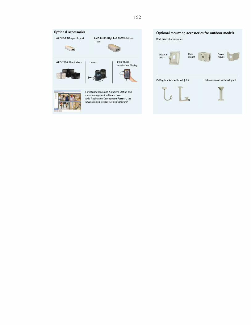
152