Embed Size (px)
Citation preview

PRE FEASIBILITY REPORT
OF
Feedchem Inc.
Survey No. 165, Radhe industrial Area, B/h Varun casting,
Village: Kothariya, Rajkot.
M: 9879092804
Prepared By:
Mr. Deepak Asodariya- Partner
Email ID: [email protected]

INTRODUCTION
Gujarat is a leading state concern as industrial growth. Feedchem Inc. is located at Sr. No.: 165, Radhe Industrial Area, B/h Varun Casting,
Kothariya, Rajkot, Gujarat wants toManufacture different organic chemical products. For manufacturing these products different organic and inorganic chemicals will be used as a raw materials for these organic products manufacturing industry wants Environmental Clearance. So that the industry has to prepare Pre-Feasibility report. For this report we have collected following data for total production: Raw materials, Production, Manufacturing process, Water consumption, Waste water generation, Stack details, fuel consumption & Solid waste generation

LIST OF ANNEXURES Sr. No. Description
1 List of product
2 List of raw materials
3 Manufacturing Process
4 Water Balance
5 ETP Lay-Out
6 Details of Air Emission
7 Solid waste management
8 Conclusion
-

1.List of Products
Sr.No. Name of Product Production Capacity, MT/M
1 Furan Resin 60
2 Paratoluenesulphonic acid based hardner for Furan resin
30
3 Phenol Formaldehyde resin 20
4 Paratoluenesulphonic acid based hardner for PF resin
10
5 Alkaline Phenolic Resin 20
6 Aluminium based pasting agent 1
7 Sodium silicate based paste 3
8 Graphite solvent based coating 20
9 Zircon solvent based coating 30
10 Zircon water based coating 5
11 Aluminium silicate water based coating 40
12 Aluminium silicate solvent based coating 15
13 Magnesite solvent based coating 5
14 Cashew nut shell based Resin 40

2. List of Raw Materials
Sr. No
Name Of Product Name Of Raw Material Qty/MT Total Qty MT/Month
1 Furan Resin 1. Furfuryl alcohol 2. Formalin
0.74 0.285
44.4 17.1
2
Paratoluenesulphonic acid based hardner for Furan resin
1. PTSA 2. Sulphuric acid 3.Water
0.675 0.025
0.3
20.25 0.75
9
3 Phenol Formaldehyde resin
1. Phenol 2. Formalin
0.54 0.46
10.8 9.2
4
Paratoluenesulphonic acid based hardner for PF resin
1. PTSA 2. Sulphuric Acid 3.Water 4. HF
0.675 0.025 0.298 0.002
6.75 0.25 2.98 0.02
5 Alkaline Phenol Formaldehyde resin
1. Phenol 2. Formalin 3.pH Adjust
0.54 0.46
10.8 9.2
6 Aluminium based Pasting agent
1. Al- Paste 2. Hexane 3.aluminium silicate 4.Mica
0.3 0.655 0.025 0.020
0.3 0.655 0.025 0.020
7 Sodium Silicate based paste
1. Sodium Silicate 2. Silica Flour 3.ball clay 4.Mica
0.5 0.4
0.055 0.045
1.5 1.2
0.165 0.135
8 Graphite Solvent based coating
1. Silica 2.Graphite 3.Attapulgite 4. Water 5. Ball Clay 6.Rosin 7. Methanol
0.29 0.30 0.02 0.03 0.03
0.055 0.275
5.8 6
0.4 0.6 0.6 1.1 5.5
9 Zircon solvent based coating
1. IPA 2. Water 3. Attapulgite 4. Methanol 5.toluene 6.Zircon Silicate 7.Mica 8.Ballclay
0.020 0.020 0.020 0.300 0.005 0.600 0.025 0.010
0.6 0.6 0.6 9
0.5 18
0.75 0.3

10 Zircon water based coating
1. Water 2. Zircon Silicate 3. Bentonite 4. Ball clay
0.27 0.70
0.015 0.015
1.35 3.5
0.075 0.075
11 Aluminium Silicate water based coating
1. Water 2. Bentonite 3. Attapulgite 4. Graphite 5. Silica 6. Mica 7.Aluminium Silicate
0.37 0.060
0.2 0.075 0.010 0.125 0.16
14.8 2.4 8 3
0.4 5
6.4
12 Aluminium Silicate solvent based coating
1. Methanol 2. Rosin 3. Aluminium Silicate 4. Bentonite 5.Ball Clay 6. Soap Stone 7.Mica
0.4 0.02 0.3
0.015 0.015 0.15 0.10
6 0.3 4.5
0.225 0.225 2.25 1.5
13 Magnesite Solvent based coating
1. Hexane 2. Methanol 3.Magnesite Powder 4.Bentonite 5.Water
0.07 0.34 0.50
0.015 0.075
0.35 17 2.5
0.075 0.375
14 Cashew Nut Shell based Resin
1. CNSL 2. Hexamine 3. Methanol 4. Liquid Hardners
0.740 0.05 0.14 0.07
29.6 2
5.6 2.8

3.Manufacturing Process
1. Furan Resin
Process:
i. Raw materials like Furfuryl alcohol and formalin are charged into SS reaction vessel
and mixed.
ii. This reaction mass is being heated up to 100-105 °C and water is distilled out.
iii. The whole mass is cooled down to 40 °C.
iv. This finished product is then packed in MS/HDPE drums or HDPE carboys.
Flow Chart:
2. Paratoluenesulphonic Acid based harder for Furan Resin
Process:
i. Raw material like paratoluenesulphonic acid, water &sulphuric acid are added to
reactor and blended for specific time.
ii. This finished product is then packed in MS/HDPE drums or HDPE carboys.
Furfuryl alcohol 740kg +
Formalin 285 kg REACTOR (100-105°C)
Condensate to ETP
25kg
Mixing
40°C
Furan Resin 1000kg

Flow chart:
3. Phenol Formaldehyde Resin
Process:
i. Raw materials like phenol & formaldehyde are charged into SS reaction
vessel.
ii. This reaction mass is being heated up to 60 °C or exothermic reaction takes
place.
iii. The whole mass is transferred to mixing vessel and it is cooled down to 40
°C.
iv. This finished product is then packed in MS/HDPE drums or HDPE carboys.
Flow Chart:
4. Paratoluenesulphonic Acid based harder for Phenol formaldehyde Resin
Process:
i. Raw material like paratoluenesulphonic acid, water, sulphuric acid &Hydrofloric
acid are added to reactor and blended for specific time.
ii. This finished product is then packed in MS/HDPE drums or HDPE carboys.
Flow chart:
Paratoluenesulphonic
acid 675kg + Water
300kg + sulphuric acid
25kg
REACTOR(Blending)
PTSA harder 1000kg
Phenol 540kg
+Formaline 460 kg
REACTOR (60°C)
Mixing
40°C
Phenol Formaldehyde resin
1000kg

5. Alkaline Phenol Formaldehyde Resin
Process:
i. Raw materials like phenol & formaldehyde are charged into SS reaction vessel.
ii. This reaction mass is being heated up to 60 °C or exothermic reaction takes
place.
iii. The whole mass is transferred to mixing vessel and it is cooled down to 40
°C.
iv. pH is adjusted as per requirement.
v. This finished product is then packed in MS/HDPE drums or HDPE carboys.
Flow Chart:
Paratoluenesulphonic
acid 675kg + Water
298kg + sulphuric acid
25kg + HF 2kg
REACTOR (Blending)
PTSA harder 1000kg
Phenol 550kg +
Formalin 450kg
REACTOR (60°C)
Mixing
40°C
pH adjustment
Alkaline Phenol Formaldehyde
resin 1000kg

6. Aluminium silicate water based coating
Process:
i. Raw materials like attapulgite, bentonite, silica and water are added to vessel and
mixed.
ii. After some time interval graphite, mica &aluminium silicate are added and mixing is
done.
iii. Finally the mixed paste is diluted with water.
iv. This finished product is then packed in MS/HDPE drums or HDPE carboys
Flow chart:
7. Aluminium silicate Solvent based coating
Process:
i. Raw materials like methanol, bentonite& ball clay are added to vessel and mixed.
ii. After some time interval Rosin, methanol, soap stone, mica &aluminium silicate are
added and mixing is done.
iii. Finally the mixed paste is diluted with methanol.
iv. This finished product is then packed in MS/HDPE drums or HDPE carboys
Attapulgite 200kg+
Bentonite 220kg +
Silica 10kg + water
170kg
Mixing
Mixing
Mixing
Aluminium silicate water
based coating 1000kg
Graphite75kg +
Mica 125 kg
Water 200 kg

Flow chart:
8. Zircon water based coating
Process:
i. Raw material like bentonite, ball clay & water are added in vessel and mixed.
ii. After some time interval zircon silicate is added and mixing is done.
iii. Finally viscosity is maintained by adding water.
iv. This finished product is then packed in MS/HDPE drums or HDPE carboys
Flow chart:
Methanol 150kg+
Bentonite 15kg +
ball clay 15kg
Mixing
Mixing
Mixing
Aluminium silicate solvent
based coating 1000kg
Rosin 20kg + Methanol
50kg + Soapstone
150kg+Mica 100kg+
aluminium silicate
300kg
Dilution with
methanol 200 kg
water 120kg+
Bentonite 15kg +
ballclay 15kg
Mixing
Mixing
Mixing
Zircon water based coating
1000kg
Zircon silicate 700kg
Water 150kg
(viscosity maintain)

9. Graphite solvent based coating
Process:
i. Raw materials like attapulgite, ball clay, rosin, methanol and water are added in
vessel and mixed
ii. After some time interval graphite and silica are added and mixed.
iii. Finally the mixed paste is diluted with methanol.
iv. This finished product is then packed in MS/ HDPE drums or HDPE carboys
Flow chart:
10. Magnesite solvent based coating
Process:
i. Raw materials methanol, hexane and bentonite are added in vessel and mixed
ii. After some time interval magnesite powder and water are added and mixed
iii. Finally the mixed paste is diluted with methol.
iv. This finished product is then packed in MS/HDPE drums or HDPE carboys
Methanol 100kg+
water 30kg + ball
clay 30kg+
attapulgite 20kg +
rosin 55kg
Mixing
Mixing
Mixing
Graphite solvent based
coating 1000kg
Graphite 300kg +
silicate 290kg
Dilution with
methanol 175 kg

Flow chart:
11. Zircon solvent based coating
Process:
i. Raw materials methanol, IPA, toluene and water are added in vessel and mixed
ii. After certain time attapulgite, zircon silicate, mica and ballclay are added and
mixed
iii. Finally the mixed paste is diluted with methol.
iv. This finished product is then packed in MS/HDPE drums or HDPE carboys
Flow chart:
Hexane 70kg+
methanol 150kg +
bentonite 15kg
Mixing
Mixing
Mixing
Magnesite solvent based
coating 1000kg
Magnesitepowder
500kg + water 75kg
Methanol 190kg
(dilution)
IPA 20kg+
methanol 100kg +
toluene 5kg +
water 20kg
Mixing
Mixing
Mixing
Zircon solvent based coating
1000kg
Attapulgite 20kg +
Zircon silicate 600kg +
Mica 25kg + ballclay
10kg
Methanol 200kg
(dilution)
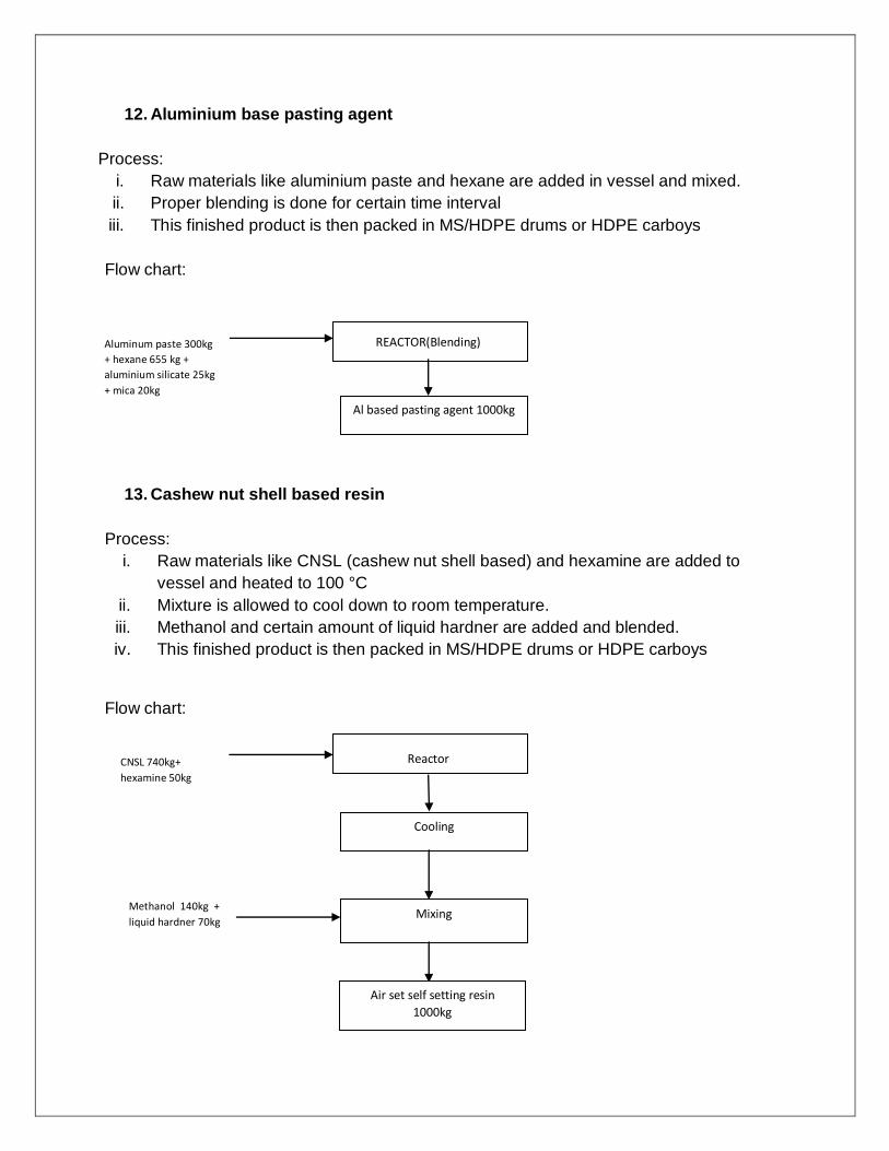
12. Aluminium base pasting agent
Process:
i. Raw materials like aluminium paste and hexane are added in vessel and mixed.
ii. Proper blending is done for certain time interval
iii. This finished product is then packed in MS/HDPE drums or HDPE carboys
Flow chart:
13. Cashew nut shell based resin
Process:
i. Raw materials like CNSL (cashew nut shell based) and hexamine are added to
vessel and heated to 100 °C
ii. Mixture is allowed to cool down to room temperature.
iii. Methanol and certain amount of liquid hardner are added and blended.
iv. This finished product is then packed in MS/HDPE drums or HDPE carboys
Flow chart:
Aluminum paste 300kg
+ hexane 655 kg +
aluminium silicate 25kg
+ mica 20kg
REACTOR(Blending)
Al based pasting agent 1000kg
CNSL 740kg+
hexamine 50kg
Reactor
Cooling
Mixing
Air set self setting resin
1000kg
Methanol 140kg +
liquid hardner 70kg

14. Sodium silicate based paste
Process:
i. Raw materials like sodium silicate and silica flour are added in vessel
ii. Mixture is blended for certain period of time
iii. This finished product is then packed in MS/HDPE drums or HDPE carboys
Flow chart:
Sodium silicate 500kg +
silica flour 400 kg + ball
clay 55kg + mica 45kg
REACTOR(Blending)
Sodium silicate 1000kg

4. Water Balance Diagram
*Note: All figures are in KL/Day
Note: Source of fresh water is bore well.
INTAKE
2.8
DOMESTIC
0.5
GARDENING
1.3
INDUSTRIAL
1.0
SEWAGE
0.4
PROCESS
0.7
UTILITIES
0.3
CONDENSATE
0.05
SOAK PIT
0.4
HOLDING TANK
0.1
UTILITIES
0.05
EVAPORATION
0.1

5. Proposed Effluent Treatment Plant
Maximum 0.1 kld effluent to be generated from process and it will be evaporated. Evaporation residue shall be sent to TSDF for final disposal.
Effluent from
process &
cooling tower
Collection cum
equalization tank
1×1×0.5 m
Evaporator
Capacity: 15 l/hr

6. Stack Details
Flue Gas Emission
Sr. No. Stack Attached Stack Height Pollutants
1 Steam Boiler 12 PM<150 mg/Nm3
SO2< 100 ppm
NOx< 50 ppm 2
D.G. Set (200 KVA) (Stand By)
5
Process Gas Emission
There is no process gas emission from manufacturing process.

7. DETAILS OF SOLID WASTE
Sr.No. Types Of
Waste Category Quantity
Storage
Area Mode Of Disposal
1 Evaporation
Residue 37.3 5kg/Month 9 m
2
Collection, Storage,
Transportation,
Disposal At TSDF
Site.
2 Used Oil / Spent
Oil 5.1 25 Lits/Yr 4 m
2
Collection, Storage, Transportation, Sell
To Registered Reprocesser
3
Discard
Container/ Drum
33.3
100
Nos./Month 10 m
2
Sold To
Registered
Reprocessor
Bags 5000
Nos./Month 10 m
2
Sold To
Registered
Recycler

8. CONCLUSION
The industry will generate 0.1 kl/Day of effluent. The proposed ETP will be well designed to treat 0.1 kl/Day effluent. Whatever the pollution load will generate managed by the industry and facility provided. ETP will have one collection cum equalization tank & evaporator. Total effluent generation will be around100 L/D i.e. Effluent load will be 8.33 liter/hr. approximately. Collection tank (CT) adequacy : Volume of CT500 Liter Effluent load 8.33 Liter/hr.
SO IT IS ADEQUATE.
Collection tank is five times of capacity against generation of effluent and evaporator capacity is also adequate to evaporate whole effluent generated in approx. 6 hrs.