Embed Size (px)
Citation preview
Office for Nuclear RegulationAn agency of HSE
…
Generic Design Assessment – New Civil Reactor Build
Step 4 Structural Integrity Assessment of the EDF and AREVA UK EPRTM Reactor
Assessment Report: ONR-GDA-AR-11-027 Revision 0
14 November 2011

Office for Nuclear Regulation An agency of HSE
Report ONR-GDA-AR-11-027Revision 0
Page (ii)
COPYRIGHT
© Crown copyright 2011
First published December 2011
You may reuse this information (excluding logos) free of charge in any format or medium, under the terms of the Open Government Licence. To view the licence visit www.nationalarchives.gov.uk/doc/open-government-licence/, write to the Information Policy Team, The National Archives, Kew, London TW9 4DU, or email [email protected].
Some images and illustrations may not be owned by the Crown so cannot be reproduced without permission of the copyright owner. Enquiries should be sent to [email protected].
Unless otherwise stated, all corporate names, logos, and Registered® and Trademark™ products mentioned in this Web site belong to one or more of the respective Companies or their respective licensors. They may not be used or reproduced in any manner without the prior written agreement of the owner(s).
For published documents, the electronic copy on the ONR website remains the most current publically available version and copying or printing renders this document uncontrolled.

Office for Nuclear Regulation An agency of HSE
Report ONR-GDA-AR-11-027Revision 0
Page (iii)
PREFACE
The Office for Nuclear Regulation (ONR) was created on 1st April 2011 as an Agency of the Health and Safety Executive (HSE). It was formed from HSE's Nuclear Directorate (ND) and has the same role. Any references in this document to the Nuclear Directorate (ND) or the Nuclear Installations Inspectorate (NII) should be taken as references to ONR.
The assessments supporting this report, undertaken as part of our Generic Design Assessment (GDA) process and the submissions made by EDF and AREVA relating to the UK EPRTM reactor design, were established prior to the events at Fukushima, Japan. Therefore, this report makes no reference to Fukushima in any of its findings or conclusions. However, ONR has raised a GDA Issue which requires EDF and AREVA to demonstrate how they will be taking account of the lessons learnt from the events at Fukushima, including those lessons and recommendations that are identified in the ONR Chief Inspector’s interim and final reports. The details of this GDA Issue can be found on the Joint Regulators’ new build website www.hse.gov.uk/newreactors and in ONR’s Step 4 Cross-cutting Topics Assessment of the EDF and AREVA UK EPRTM Reactor.

Office for Nuclear Regulation An agency of HSE
Report ONR-GDA-AR-11-027Revision 0
Page (iv)
EXECUTIVE SUMMARY
This report presents the findings of the Structural Integrity assessment of the UK EPR reactor undertaken as part of Step 4 of the Health and Safety Executive’s Generic Design Assessment (GDA). The assessment has been carried out on the Pre-construction Safety Report (PCSR) and supporting documentation submitted by EDF and AREVA during Step 4.
The Step 4 assessment built on the assessments already carried out for Steps 2 and 3 and reviewed the safety aspects of the UK EPR reactor in greater detail, by examining the evidence, supporting arguments and claims made in the safety documentation. This has enabled me to make judgements on the adequacy of the Structural Integrity information contained within the PCSR and supporting documentation.
It is seldom possible, or necessary, to assess a safety case in its entirety, therefore sampling is used to limit the areas scrutinised and to improve the overall efficiency of the assessment process. Sampling is done in a targeted and structured manner with a view to revealing any topic-specific or generic weaknesses in the safety case. To identify the sampling an assessment plan for Step 4 was set out in advance. A number of items have been agreed with EDF and AREVA as being outside the scope of the GDA process and hence have not been included in my assessment.
My assessment has focussed on the nuclear safety-related metal pressure vessels and piping and other pressure boundary components including:
Safety function categorisation and classification of systems, structures and components.
Materials selection, design, fabrication.
In-manufacture examination and testing.
The analysis of structural integrity under normal load and faulted conditions (including fracture mechanics based analyses).
Lifetime ageing of materials (including neutron irradiation embrittlement).
Nuclear pressure vessels and piping are designed to internationally accepted design codes and EDF and AREVA have designed the EPR against the French nuclear design code, RCC-M. The design requirements set by the RCC-M code have been reviewed: they are broadly the same as those for ASME III on a class by class basis and are judged to be generally acceptable for nuclear pressure systems.
However, there are a few critical components for which it is necessary to show that the likelihood of gross failure is so low that it can be discounted. In the UK we do not accept that the normal code requirements are sufficient to provide this level of confidence and we expect a higher level of demonstration of structural integrity. EDF and AREVA have accepted the need to make this demonstration in line with UK practice.
EDF and AREVA have designated these components as High Integrity Components (HICs). Given their significance and the need for a demonstration against UK practice, I have concentrated on the demonstration of integrity for the HICs and I have satisfied myself that the process for identifying them is adequate.
The evidence to show that the likelihood of failure is so low that it can be discounted includes an avoidance of fracture demonstration which integrates fracture mechanics analyses, material toughness and qualification of manufacturing inspections. EDF and AREVA accepted the requirement to determine a limiting defect size and to demonstrate that the proposed inspection techniques were capable of detecting these with some margin. However, the proposed fracture mechanics methodology is different from that normally used in the UK nuclear industry and the
Office for Nuclear Regulation An agency of HSE
Report ONR-GDA-AR-11-027Revision 0
Page (v)
inspection techniques also have some novel features. This area was therefore reviewed in some depth.
I tested the adequacy of the fracture mechanics approach by comparing a number of representative but challenging assessments with results obtained by a UK contractor using the R6 approach normally used in the UK. Initial comparisons were not close for transients with a significant thermal stress and this resulted in reviews of both the French RSE-M methodology and the UK R6 methodology. Following this review EDF and AREVA have developed an alternative approach which I am satisfied gives broadly the same results as an R6 assessment.
EDF and AREVA’s original inspection proposals appeared unlikely to be sufficiently targeted to defects of the most likely orientation to be capable of being qualified within the UK. These concerns were discussed in some detail within GDA and have resulted in proposals for the ferritic welds in the main vessels which appear to be generally satisfactory. However the proposals are not yet sufficiently developed for the austenitic and dissimilar metal welds in the reactor coolant loop pipework, and this is taken forward within a GDA Issue on avoidance of fracture.
EDF and AREVA have submitted all the planned reports on avoidance of fracture for the HICs, however a number of the important reports arrived later than had been originally planned and I have been unable to undertake a full assessment within the timescales allowed for GDA Step 4. Based on a high level review, I have sufficient confidence in the approach to conclude that it should be possible to provide a suitable demonstration for the safety case and thereby to support an Interim Design Acceptance Certificate (IDAC). However a more detailed assessment post GDA Step 4 will be required to confirm that an adequate justification has been made before I am confident to support a Design Acceptance Certificate (DAC). A GDA Issue on avoidance of fracture has been created to support this ongoing assessment work post Step 4 and to provide additional evidence to justify claims for non-destructive testing capability.
EDF and AREVA propose to position surveillance samples between the reactor core and the reactor pressure vessel to enable a future Licensee to determine the reduction in fracture toughness due to irradiation over the plant lifetime. However, because the samples are closer to the heavy reflector than is the vessel wall, the energy spectrum of the neutrons which irradiate the samples will differ significantly from that seen by the vessel. Consequently a prediction of irradiation damage based solely on high energy neutrons as is currently proposed might lead to error. I have raised a GDA Issue on the surveillance scheme asking the requesting parties to explain how the surveillance scheme takes account of this difference in the neutron energy spectra.
For the remaining important vessels and components the design will be based on the normal requirements of the French nuclear design code RCC-M which I judge to be generally acceptable. However EDF and AREVA have developed a mechanical classification scheme which can result in the requirements being downgraded in a manner which appears not to be consistent with Health and Safety Executive’s Safety Assessment Principles. This will be pursued as part of ND’s Cross-cutting GDA Issue on classification of systems, structures and components.
In addition, I do not judge that the consequences of failure of RCC-M vessels, tanks, pumps and valves have been adequately addressed. This will be pursued in the Internal Hazards area as a GDA Issue on consequence analysis for failure of RCC-M components.
The GDA Issues discussed above are of particular significance and will require resolution before the Health and Safety Executive would agree to the commencement of nuclear safety-related construction of a UK EPR reactor in the UK. The two structural integrity GDA Issues are listed in Annex 2: the issue on avoidance of fracture has seven actions whilst the issue on the surveillance scheme has one action.
Office for Nuclear Regulation An agency of HSE
Report ONR-GDA-AR-11-027Revision 0
Page (vi)
I have also identified several areas of a Licensee or site specific nature that do not need to be addressed as part of the GDA process but which will need to be followed up by any Licensee and these are listed in Annex 1 as Assessment Findings.
Some examples of my Assessment Findings are:
The new material option 20MND5 is acceptable for the proposed use, but there will be a need to tighten the composition limits for certain elements and sample non-destructive testing should be performed to check that underclad cracks are avoided.
The nickel content of the Reactor Pressure Vessel (RPV) beltline welds should be limited.
Scoping calculations should be performed for the limiting locations of the HICs in advance of the manufacturing inspections to show that a through life case can be made when the lifetime fatigue crack growth is taken into account.
Operational limits should be set to ensure that the RPV operating pressure and temperature are always separated from the Pressure-Temperature limit curve by a significant margin.
Overall, based on the sample undertaken in accordance with ND procedures, I am broadly satisfied that the claims, arguments and evidence laid down within the PCSR and supporting documentation submitted as part of the GDA process present an adequate safety case for the generic UK EPR reactor design. The UK EPR reactor is therefore suitable for construction in the UK, subject to satisfactory progression and resolution of GDA Issues and assessment of additional information that becomes available as the GDA Design Reference is supplemented with additional details on a site-by-site basis.

Office for Nuclear Regulation An agency of HSE
Report ONR-GDA-AR-11-027Revision 0
Page (vii)
LIST OF ABBREVIATIONS
ALARP As Low As Reasonably Practicable
ASN Autorité de Sûreté Nucléaire (French nuclear safety authority)
BMS (Nuclear Directorate) Business Management System
DMW Dissimilar Metal Weld
DAC Design Acceptance Confirmation
DSM Defect Size Margin
EASL Engineering Analysis Services Limited
EDF and AREVA Electricité de France SA and AREVA NP SAS
ELLDS End of Life Limiting Defect Size
ENIQ European Network for Inspection and Qualification
EPRI Electric Power Research Institute
FA3 Flamanville 3 (A French EPR under construction)
FMA Fracture Mechanics Analysis
GDA Generic Design Assessment
HAZ Heat Affected Zone
HIC High Integrity Component
HSE The Health and Safety Executive
IAEA The International Atomic Energy Agency
IDAC Interim Design Acceptance Confirmation
LOCA Loss of Coolant Accident (2A LOCA – double-ended pipe break LOCA)
LFCG Lifetime Fatigue Crack Growth
MDEP Multi-national Design Evaluation Programme
MCL Main Coolant Line (synonymous with RCL)
MSL Main Steam Line
ND The (HSE) Nuclear Directorate
NDT Non-Destructive Testing
NNL National Nuclear Laboratory
NSL Nuclear Site Licensing
OL3 Olkiluoto 3 (A Finnish EPR plant under construction)
PCSR Pre-construction Safety Report
POSR Pre-Operational Safety Case
PSA Probabilistic Safety Analysis
PZR Pressuriser
Office for Nuclear Regulation An agency of HSE
Report ONR-GDA-AR-11-027Revision 0
Page (viii)
LIST OF ABBREVIATIONS
P-T (limits) Pressure-Temperature Limits
QB Qualification Body
QEDS Qualified Examination Defect Size
RCL Reactor Coolant Loop
RCP Reactor Coolant Pump
RCS Reactor Coolant System
RGP Relevant Good Practice
RI Regulatory Issue
RIA Regulatory Issue Action
RO Regulatory Observation
ROA Regulatory Observation Action
RP Requesting Party
RPV Reactor Pressure Vessel
SAP Safety Assessment Principle
SG Steam Generator
SSC System, Structure and Component
SSER Safety, Security and Environmental Report
STUK The Finish Nuclear Safety Authority
TAG (Nuclear Directorate) Technical Assessment Guide
TAGSI UK Technical Advisory Group on Structural Integrity
TJ Technical Justification
TQ Technical Query
TSC Technical Support Contractor
TWI The Welding Institute
US NRC Nuclear Regulatory Commission (United States of America)
UT Ultrasonic Testing

Office for Nuclear Regulation An agency of HSE
Report ONR-GDA-AR-11-027Revision 0
Page (ix)
TABLE OF CONTENTS
1 INTRODUCTION...................................................................................................................... 1
2 NUCLEAR DIRECTORATE’S ASSESSMENT STRATEGY FOR STRUCTURAL INTEGRITY 2 2.1 Assessment Plan ............................................................................................................ 2 2.2 Standards and Criteria .................................................................................................... 3 2.3 Assessment Scope ......................................................................................................... 3
2.3.1 Findings from GDA Step 3............................................................................................. 4 2.3.2 Step 4 Structural Integrity Assessment ......................................................................... 4 2.3.3 Use of Technical Support Contractors........................................................................... 5 2.3.4 Cross-cutting Topics ...................................................................................................... 5 2.3.5 Integration with Other Assessment Topics .................................................................... 6 2.3.6 Out of Scope Items ........................................................................................................ 6
3 REQUESTING PARTY’S SAFETY CASE ............................................................................... 8 3.1 UK EPR PCSR Overview of Structure and Relevant Content ........................................ 8 3.2 UK EPR PCSR Outline of Safety Case Claims for Structural Integrity of Pressure
Boundary Components ................................................................................................... 8 3.2.1 Safety Functions Supported by Pressure Boundary Components................................ 8 3.2.2 Classification of Mechanical (Pressure Boundary) Components and Identification of
HICs ............................................................................................................................... 9 3.2.3 Avoidance of Fracture for HICs ................................................................................... 11
3.3 Key Features of the Design of High Integrity Components (from PCSR Chapter 3.1 (2011) Sections 1.2.1.4.1 and 1.2.1.4.2)....................................................................... 12
3.4 UK EPR PCSR Outline of Arguments and Evidence to Support the Claims for Structural Integrity ......................................................................................................................... 13 3.4.1 Specific Requirements for Break Preclusion ............................................................... 14
3.5 Categorisation and Classification.................................................................................. 15
4 GDA STEP 4 NUCLEAR DIRECTORATE ASSESSMENT FOR STRUCTURAL INTEGRITY 16 4.1 Categorisation and Classification of Structures, Systems and Components - “Non
Breakable, “Break Preclusion” and “No Missile” Items ................................................. 16 4.1.1 Background, Summary of Step 3 Activities and Definition of Step 4 Actions.............. 16 4.1.2 Justification of the List of Components Whose Risk of Failure Is So Low That It Can
Be Discounted ............................................................................................................. 17 4.1.3 Conclusions and Findings Relating to Identification of High Integrity Components.... 19
4.2 Avoidance of Fracture - Margins Based on Size of Crack-Like Defects. ...................... 19 4.2.1 Background and Definition of Step 4 Actions .............................................................. 19 4.2.2 Overview of Position Reached at the End of GDA Step 4........................................... 22 4.2.3 Fracture Mechanics Analyses ..................................................................................... 22 4.2.4 Non-Destructive Examinations During Manufacture ................................................... 40 4.2.5 Derivation of Materials Toughness Data ..................................................................... 59 4.2.6 Overall Conclusions and Findings Relating to Avoidance of Fracture ........................ 64
4.3 Materials Specifications and Selection of Material Grade – Reactor Pressure Vessel, Pressuriser, Steam Generator Shells ........................................................................... 65
Office for Nuclear Regulation An agency of HSE
Report ONR-GDA-AR-11-027Revision 0
Page (x)
4.3.1 Background.................................................................................................................. 65 4.3.2 Assessment of Generic Materials Specifications......................................................... 66 4.3.3 Review of the Proposal to Introduce 20MND5 as an Option for Steam Generator and
Pressuriser Shells........................................................................................................ 73 4.4 Effects of Irradiation on RPV Cylindrical Shell and Circumferential Welds................... 78
4.4.1 Overview of Irradiation Embrittlement Issues.............................................................. 78 4.4.2 Step 4 Assessment...................................................................................................... 79 4.4.3 Conclusions and Findings Relating to Irradiation Damage ......................................... 82
4.5 Pressure - Temperature Limit Diagrams and Low Temperature Overpressure Protection...................................................................................................................................... 83 4.5.1 Background and Key Issues from Step 3 Assessment ............................................... 83 4.5.2 Key points from the Assessment during Step 4........................................................... 84 4.5.3 Conclusions and Findings relating to Reactor Pressure Vessel Pressure -Temperature
Limit Diagrams and Low Temperature Overpressure Protection ................................ 87 4.6 RCC-M Issues............................................................................................................... 87
4.6.1 RCC-M Aspects of Requirements for Design Analysis of Piping Class 1, 2 and 3 ..... 87 4.6.2 Comparison of RCC-M and ASME Welding III Procedures ........................................ 92 4.6.3 Review of RCC-M Design Requirements for Pressure Boundaries of Pumps and
Valves .......................................................................................................................... 97 4.7 Environmental Effects on Fatigue Design Curves ........................................................ 98
4.7.1 Current Position and the Way Forward ....................................................................... 98 4.7.2 Conclusions and Findings on Environmental Effects on Fatigue Design Curves ..... 100
4.8 Documentary Envelope for Specific Components ...................................................... 100 4.8.1 Generic and Site Specific Safety-related Documents for Primary Circuit Pressure
Boundary Components. ............................................................................................. 101 4.8.2 Review of Design Reports ......................................................................................... 102 4.8.3 Conclusions and Findings Relating to the Documentary Envelope .......................... 105
4.9 Generic Categorisation and Classification Issues....................................................... 105 4.9.1 Background................................................................................................................ 105 4.9.2 Review of Reports on SIS Accumulator Integrity ...................................................... 107 4.9.3 Failure of RCC-M Pressure Vessels and Pipework: Internal Hazards GDA Issue.... 109 4.9.4 Exclusion of Failure Components in Fuel Building – PCSR Chapter 13.2 Section 6.3
................................................................................................................................... 110 4.9.5 Conclusions and Findings Relating to Categorisation............................................... 111
4.10 Review of the Access Requirements for In-Service Inspection (ISI)........................... 111 4.10.1 Background................................................................................................................ 111 4.10.2 Key Points from the Assessment During Step 4 ....................................................... 112 4.10.3 Conclusions and Findings Relating to Access for In-Service Inspection .................. 113
4.11 Operation of Plant within Safe Limits .......................................................................... 114 4.11.1 Findings Relating to Operation of Plant within Safe Limits........................................ 114
4.12 Other Matters .............................................................................................................. 115 4.12.1 Component Internals ................................................................................................. 115 4.12.2 Comparison of Design of Break Preclusion Pipework in UKEPR and Earlier Reactors
(Report TR ECEMA101022)...................................................................................... 117 4.12.3 Pressuriser Heater Design......................................................................................... 119 4.12.4 Welding of Control Rod Penetrations in EPR RPV Head.......................................... 120

Office for Nuclear Regulation An agency of HSE
Report ONR-GDA-AR-11-027Revision 0
Page (xi)
4.12.5 Fatigue Usage Factor Analysis for Primary Circuit Pipework.................................... 122 4.13 Overseas Regulatory Interface ................................................................................... 122
4.13.1 Bilateral collaboration ................................................................................................ 122 4.13.2 Multilateral Collaboration ........................................................................................... 123
4.14 Interface with Other Regulators .................................................................................. 123 4.15 Other Health and Safety Legislation ........................................................................... 123
5 CONCLUSIONS................................................................................................................... 124 5.1 Key Findings from the Step 4 Assessment ................................................................. 125
5.1.1 Assessment Findings................................................................................................. 125 5.1.2 GDA Issues................................................................................................................ 126
6 REFERENCES..................................................................................................................... 127
Figures
Figure 1: RPV Diagram from SDM RCS Part 3 (Ref. 128)
Figure 2: EPR Mechanical Design Logic for Pressure Boundary Components from PEER-F 10.0134/A (Ref. 129)
Tables
Table 1: Relevant Safety Assessment Principles for Structural Integrity Considered During Step 4
Table 2: Main Parts of UK EPR PCSR Relevant to Structural Integrity Assessment
Table 3: Areas for Further Assessment during Step 4 (Derived from the Step 4 Assessment Plan)
Table 4: Reactor Pressure Vessel Materials Compositions
Table 5: Steam Generator and Pressuriser Materials Compositions
Annexes
Annex 1: Assessment Findings to Be Addressed as Normal Regulatory Business During the Forward Programme of This Reactor – Structural Integrity – UK EPR
Annex 2: GDA Issues – Structural Integrity – UK EPR
Office for Nuclear Regulation An agency of HSE
Report ONR-GDA-AR-11-027Revision 0
Page 1
1 INTRODUCTION
1 This report presents the findings of the Step 4 Structural Integrity assessment of the UK EPR reactor Pre-construction Safety Report (PCSR) (Refs 1 and 2) and supporting documentation provided by EDF and AREVA under the Health and Safety Executive's (HSE) Generic Design Assessment (GDA) process. Assessment was undertaken of the PCSR and the supporting evidence derived from the Submission Master List (Ref. 159). The approach taken was to assess the principal submission, i.e. the PCSR, and then undertake assessment of the relevant documentation on a sampling basis in accordance with the requirements of ND Business Management System (BMS) procedure AST/001 (Ref. 4). The Safety Assessment Principles (SAPs) (Ref. 5) have been used as the basis for this assessment. Ultimately, the goal of assessment is to reach an independent and informed judgment on the adequacy of a nuclear safety case.
2 During the assessment a number of Regulatory Observations (RO) and Technical Queries (TQ) were issued and the responses made by EDF and AREVA assessed. Where relevant, detailed design information from other projects for this reactor type has been assessed to build confidence and assist in forming a view as to whether the design intent proposed within the GDA process can be realised.
3 A number of items have been agreed with EDF and AREVA as being outside the scope of the GDA process and hence have not been included in this assessment.

Office for Nuclear Regulation An agency of HSE
Report ONR-GDA-AR-11-027Revision 0
Page 2
2 NUCLEAR DIRECTORATE’S ASSESSMENT STRATEGY FOR STRUCTURAL INTEGRITY
2.1 Assessment Plan
4 The intended assessment strategy for Step 4 for the structural integrity topic area was set out in an assessment plan (Ref. 6) that identified the intended scope of the assessment and the standards and guidance that would be applied. This is summarised below.
5 The objective of the Step 4 assessment is to make a judgement on the adequacy of the claims, arguments and evidence in the area of structural integrity contained within the PCSR and Supporting Documentation. Assessment in Step 4 builds on the assessment carried out in Steps 2 and 3 and is oriented toward the evidence end of the spectrum of claims, arguments and evidence.
6 The overall bases for the start of assessment in GDA Step 4 are:
The update to the Safety Submission/PCSR and the Master Submission List that were received in November 2009 (Refs 1 and 3).
Matters identified in GDA Step 3 that required further consideration and resolution within Step 4.
7 Within the Step 4 Plan the following generic HSE Commitments were required to be taken into consideration as part of the Step 4 structural integrity assessment:
Consideration of issues identified in Step 3.
Judging the design against SAPs and judging whether the proposed design reduces risks and is ALARP.
Inspections of the Requesting Party’s procedures and records.
Independent verification analyses.
Reviewing details of the design controls, procurement and quality control arrangements to secure compliance with the design intent.
Assessing arrangements for moving the safety case to an operating regime.
Assessing arrangements for ensuring and assuring that safety claims and assumptions are realised in the final design, building and construction.
Reviewing overseas progress and issues raised by overseas regulators.
Considering unresolved issues raised through the public involvement process.
Resolution of identified nuclear safety issues, or identifying paths for resolution.
8 A consolidated Safety Submission/consolidated PCSR was planned to be delivered towards the end of GDA Step 4, and the assessment in Step 4 was required to check that:
All matters that have been resolved are suitably dealt with in the consolidated Safety Submission / consolidated PCSR.
The consolidated Safety Submission/consolidated PCSR contains no new or modified material which could compromise assessment conclusions.
9 The consolidated PCSR was received in March 2011 (Ref. 2) and I have checked that the changes accurately reflect the revised safety case commitments made by EDF and
Office for Nuclear Regulation An agency of HSE
Report ONR-GDA-AR-11-027Revision 0
Page 3
AREVA for the structural integrity topic area during Step 4. I have requested some minor revisions to the PCSR, but these do not affect my assessment conclusions in this report.
2.2 Standards and Criteria
10 I have based my assessment of the structural integrity aspects of the UK EPR PCSR primarily on the following:
Safety Assessment Principles for Nuclear Facilities (SAPs, Ref. 5).
Technical Assessment Guide - Integrity of Metal Components and Structures – T/AST/16 Issue 003 (Ref. 7).
11 For the SAPs the most relevant part is “Integrity of Metal Components and Structures” in Paras 238-279, involving Principles EMC.1 to EMC.34. Another key part of the SAPs is “Ageing and Degradation” especially principles EAD.1 to EAD.4. Other topics with some relevance to this assessment are “Safety Classification and Standards” in Paras 148-161, involving Principles ECS.1 to ECS.5 and “Overpressure Protection”, SAP EPS.4. A list of these relevant SAPs is given in Table 1.
12 The assessment of the structural integrity area is on the basis of engineering practice and sound safety principles, rather than a numerical calculation of the likelihood of failure of components.
13 The UK EPR design is the outcome of many years of development and did not explicitly follow the approach to ALARP as practiced in the UK (e.g. SAPs Para. 93). As a consequence it is difficult to ‘back fit’ ALARP to the design at this stage although it is possible to examine individual important areas to determine if the situation is consistent with ALARP.
14 In carrying out my assessment, I have based my judgements of the technical aspects of structural integrity on the guidance provided on ALARP (e.g. SAPs Paras 14 and 93). I have interpreted the guidance to reach a judgement on the balance of all the factors which contribute to the structural integrity safety case.
15 Some components have a claim associated with them that gross failure is taken to be so unlikely it can be discounted. In assessing the arguments and evidence supporting this type of claim, I have applied the same basis of judgement as described above. For these claims of highest structural integrity, I have examined whether:
The proposals meet a minimum level for such a claim.
All that is reasonably practicable has been done.
2.3 Assessment Scope
16 My assessment has focussed on the nuclear safety-related metal pressure vessels and piping and other pressure boundary components including:
Categorisation and classification of systems, structures and components.
Materials selection, design, fabrication.
In-manufacture examination and testing.
The analysis of structural integrity under normal load and faulted conditions (including fracture mechanics based analyses).
Office for Nuclear Regulation An agency of HSE
Report ONR-GDA-AR-11-027Revision 0
Page 4
Lifetime ageing of materials (including neutron irradiation embrittlement).
17 Table 3 defines the scope of the Step 4 assessment, and this is based on Table 2 of the assessment plan (Ref. 6). Table 3 also lists any Technical Support Contractor (TSC) reports commissioned.
2.3.1 Findings from GDA Step 3
18 The Step 3 structural integrity assessment report (Ref. 8) showed that for Step 3, the areas chosen for assessment were mostly set within a framework of a number of Regulatory Observations. The report explained how resolution was reached in a number of areas, and indicates where further work was needed in Step 4. Examples of topics which were satisfactorily assessed during GDA Step 3 are:
the incorporation of a circumferential weld within the core region of the RPV;
the use of an austenitic casting for the RCP pump bowl casing;
the use of thermally treated Alloy 690 tubing for the steam generators.
2.3.2 Step 4 Structural Integrity Assessment
19 Table 3 shows that in general, the areas for Step 4 assessment were either covered by new Actions to existing ROs, or new ROs were established along with relevant Actions.
20 As assessment proceeded in Step 4, the direction of some activities changed. Requirements for any new deliverables were discussed with EDF and AREVA using the established processes set out in the Interface Protocol.
21 There was a substantial programme of work for EDF and AREVA under RO-UKEPR-20 concerning avoidance of fracture of the highest integrity components which have been identified via RO-UKEPR-19. Remaining activities relating to the reactor coolant pump bowls (RO-UKEPR-21) have also been consolidated under RO-UKEPR-20.
22 The response to RO-UKEPR-20 is the process by which ND gained additional confidence in the integrity of the most important structural integrity components such as the reactor pressure vessel. It is recognised that the total scope and extent of the work needed prior to reactor operation need not, and cannot, be completed within the timeframe of GDA Step 4. During GDA Step 4, judgements have to be based on the availability of sufficient information on limiting defect sizes and inspection capability. ND will need to be satisfied during the GDA process that the work to be carried out during the licensing phase will have a high likelihood of being able to achieve its purpose.
23 During Steps 3 and 4 EDF and AREVA performed work to address an aspect of an RO on irradiation damage (RO-UKEPR-25). Other Step 3 ROs with matters to be assessed in Step 4 involved materials properties for the forgings of the main vessels (RO-UKEPR-24), operational limits for pressure and temperature (RO-UKEPR-28) and aspects of pipework design using RCC-M (RO-UKEPR-36).
24 New areas of work identified in Step 3 for execution in Step 4 and included in Table 3, are:
Review of the content of documents such as:
i) Design Specifications;
ii) Analyses for loading conditions;

Office for Nuclear Regulation An agency of HSE
Report ONR-GDA-AR-11-027Revision 0
Page 5
iii) Design reports;
iv) Equipment Specifications.
Review of RCC-M welding procedures.
Review of RCC-M design requirements for the pressure boundaries of pumps and valves.
Review of accessibility for in-service inspection.
25 Also included in Table 3 is the new Step 4 topic of demonstrating that the constructed plant will be capable of being operated within safe limits, including the role of technical specification, maintenance schedule, procedures and operating limits (items 4.2 and 4.3 (a), (b) (c) and (f) in Ref. 6). Technical specifications, maintenance schedule and procedures are not required to be fully developed within Step 4, but there should be guidance available from the designer that contributes to the basis of these areas. Operating limits relevant to ensuring the safe operation of plant items of interest to the structural integrity assessment were considered.
26 Another new topic for assessment in GDA Step 4 arose from a design change to include the option of another material (20MND5) for parts of the pressure boundary of the steam generators and pressuriser.
27 My assessment has focused on the reactor coolant system (RCS), including the main components (RPV, SGs and PZR) as well as the reactor coolant loop (RCL) pipework, as they play a vital role in reactivity control, heat removal, and containment. Since I have selected the most important components for detailed assessment, I have not generally assessed the other Class 1 components in detail since their consequences of failure are claimed to be acceptable. My assessment of the safety case prepared by EDF and AREVA for the High Integrity Components (HICs) provides me some reassurance that they will have also generated an adequate safety case for those components which I have not assessed.
28 As a result of operational experience with a pressuriser heater leak at Sizewell B power station, I decided to include within my assessment the design of pressuriser heaters. This is discussed in Section 4.12.3.
2.3.3 Use of Technical Support Contractors
29 Table 5 of Ref. 6 identified 11 topics which were proposed for review by specialist contractors. All these have been performed as well as a few other topics which arose during the Step 4 assessment. The contractors used were: EASL, Serco Assurance, Professor Knott, TWI and NNL.
2.3.4 Cross-cutting Topics
30 There were a number of areas during the Step 4 assessment when there was a need to consult with other assessors. These are listed below:
Categorisation and classification – this was progressed as a cross-cutting activity under RO-UKEPR-43, but aspects relevant to structural integrity are included in this report.
Failure of pressure vessels, tanks and pipework (missiles and pipewhip).
Transients used for fracture analyses.

Office for Nuclear Regulation An agency of HSE
Report ONR-GDA-AR-11-027Revision 0
Page 6
Operational limits.
2.3.5 Integration with Other Assessment Topics
31 The need for coordination with other assessment areas was identified in Ref. 6 and the Table below summarises these:
Assessment Area Structural Integrity Aspect In
tern
al H
azar
ds
Fau
lt S
tud
ies
/ DB
A
Rea
cto
r C
hem
istr
y
Mec
han
ical
En
gin
eeri
ng
Ph
ase
2 (s
ite-
licen
sin
g)
Common position on internal hazards for pressure boundary components and rotating components.
Consistent view on range of design basis loadings for pressure boundary components. Also advice to structural integrity that thermal-hydraulics analyses that provide pressure - temperature transients are based on acceptable methods.
Ensure common understanding of reactor chemistry proposed by EDF and AREVA and any options that would be for the Licensee to decide.
Ensure common understanding of pressure relief arrangements for pressure boundary components (primary and secondary sides).
Need for coordination between ND assessors covering GDA and those involved with preparations for Phase 2 (site licensing).
2.3.6 Out of Scope Items
32 Letter ND(NII) EPR00613R (Ref. 9) identified a list of items proposed to be out of scope for GDA.
33 In response (Ref. 10) ND agreed with the structural integrity proposals and also asked to add the irradiation damage surveillance scheme. EDF and AREVA agreed with ND (Ref. 11) that although the principles of the surveillance scheme should be part of GDA, the detailed implementation would be a Licensee responsibility and part of Stage 2.
34 The consolidated list of structural integrity out of scope items (Ref. 11) is tabulated below.

Office for Nuclear Regulation An agency of HSE
Report ONR-GDA-AR-11-027Revision 0
Page 7
Out of Scope Items Justification
1. EPR project specific detailed design documents of the main components including: Requisitions, Final stress and fast fracture specifications and reports.
1. These documents take into account specific project requirements and site characteristic data. They are not generic.
2. Detailed inspection (PSI and ISI) reports.
2. Consideration of PSI/ISI proposals is out of scope for GDA. However the accessibility to deploy potential inspections techniques is within the scope of GDA. Detailed inspection plans and characteristics will be worked up with the Licensing organisation during NSL.
3. Detailed specification of Fracture Toughness tests for Avoidance of Fracture demonstration.
3. A proposal of the fracture toughness tests will be made in the frame of GDA for RO20 but the detailed specification will be worked up beyond GDA with the Licensing organisation during NSL.
4. Specific End of Manufacturing NDT qualification processes for component zones other than the prototype application for Avoidance of Fracture demonstration.
4. The development of End of Manufacturing NDT qualification process for the prototype application involves a great deal of work and adaptation to UK practise. This first case is to be provided in GDA to test appropriateness of our methodology and to develop a generic overall procedure which will be used as a basis on which to develop the detailed processes for each component zone during NSL.
5.Quality Assurance arrangement for Long Lead items.
5. Originally raised under RO22 – Due to the need to define organisational arrangements which are highly dependent on specific licensee and vendor requirements HSE and EDF and AREVA agreed to close this RO and treat the subject outside of GDA.
6. Irradiation Damage Surveillance Programme details.
6. Principles of Irradiation Damage Surveillance Programme are part of GDA (limits and conditions see RO55), but the detailed analyses and tests will be
performed with the Licensing Organisation during NSL.

Office for Nuclear Regulation An agency of HSE
Report ONR-GDA-AR-11-027Revision 0
Page 8
3 REQUESTING PARTY’S SAFETY CASE
3.1 UK EPR PCSR Overview of Structure and Relevant Content
35 The 'safety case' for the UK EPR at the start of Step 4 was contained in the 2009 PCSR (Ref. 1) During Step 4, there are several areas where the safety case has developed significantly, and these changes have been incorporated in the revised (consolidated) PCSR (Ref. 2). It is this version, representing the safety case at the end of GDA Step 4, which has been used in this section as the reference safety case. The main chapters relevant to structural integrity are listed in Table 2.
36 For the significant pressure boundary components of interest, the most important parts of the UK EPR PCSR are Chapters 3 and 5. Chapter 10 covers the main steam lines and Chapter 13 on the treatment of internals hazards has information which is also relevant to structural integrity assessment. Chapters 6 (containment) and 17 (ALARP) have less direct relevance for structural integrity but are included for completeness in Table 2.
37 ND seeks a ‘safety case’ based on a framework of ‘Claims - Arguments - Evidence’ (see Safety Assessment Principles (SAPs) SC.3, Para. 90 and SC.4 Para. 91(b), (Ref. 5) and G/AST/001.
38 The UK EPR PCSR does not use a framework of ‘Claims - Arguments - Evidence’ in an explicit way. However it does contain a significant amount of information relevant to the functional and integrity requirements of the metal pressure boundary and other components of the UK EPR design.
39 Overall, for the structural integrity aspects dealt with here, the UK EPR PCSR has about the right level of detail. The PCSR alone however is not the complete ‘safety case’. For a given component, such as the reactor pressure vessel (RPV), there will be a number of significant documents that contribute to the safety case. Such documents will include the ‘dimensioning report’ and the ‘equipment specification’. With this overall structure, the PCSR provides the ‘Claims and Arguments’ end of the framework while the supporting documents provide the ‘Evidence’ end of the framework.
40 Significant revisions have been made in Ref. 2, particularly in relation to the High Integrity Components (HICs) and the main legs which I expect to see in the safety case are now included. The structural integrity safety case is now set out adequately although the safety case for any particular component may be distributed amongst a number of sections. However there remain several important areas where I am not yet satisfied with the arguments and evidence and these are discussed in Section 4 of this report.
3.2 UK EPR PCSR Outline of Safety Case Claims for Structural Integrity of Pressure Boundary Components
3.2.1 Safety Functions Supported by Pressure Boundary Components
41 The EPR reactor design has been developed from the design of reactors in current operation. To implement the "defence-in-depth" principle, successive measures are implemented to achieve the three fundamental safety functions of reactivity control, fuel cooling and containment of radioactive material. These include the placing of successive physical barriers between radioactive materials and the environment, in particular:
1st barrier: the fuel cladding.
2nd barrier: the reactor coolant pressure boundary.
3rd barrier: the containment building.

Office for Nuclear Regulation An agency of HSE
Report ONR-GDA-AR-11-027Revision 0
Page 9
42 The principal safety functions of the UK EPR and the key pressure boundary components which contribute to maintaining these functions are listed in the table below which has been derived from the PCSR.
SSC Primary Safety
Function Safety Aspect
Reactor Coolant System (RCS)
Reactivity control
The core cooling water of the RCS, which is also used as a neutron moderator, neutron reflector and solvent for concentrated boric acid solutions, must contribute to the reactivity control independently from the rod cluster control assemblies (RCCAs).
Reactor Coolant System (RCS)
Heat transfer/ Residual heat removal
During normal operations the RCS transfers the heat generated in the reactor to the secondary loop system.
The layout of the reactor coolant system enables heat removal via natural circulation after loss of reactor coolant pumps forced flow.
The reactor coolant pump rotor equipped with its flywheel provides sufficient inertia to ensure the appropriate flow rate before the automatic shutdown of the reactor in the event of a reactor coolant pump coast-down transient.
Reactor Coolant System (RCS)
Containment of radioactive substances
The RCS acts as the second containment barrier in the event of fuel cladding failure.
The main reactor coolant system must be depressurised in the event of a severe accident (RRC-B conditions), in order to protect the integrity of the containment (third barrier).
The pressuriser safety relief valves limit the pressure within the RCS to meet the overpressure protection requirements.
Main Steam Supply System (MSSS)
Heat transfer/ residual heat removal
In normal operation, the Main Steam Supply System must remove decay heat by transferring steam to the condenser, from power operation to the connection of Residual Heat Removal System.
Under certain fault events, the MSSS must remove decay heat by dumping steam into the atmosphere to allow safe shutdown to be reached.
3.2.2 Classification of Mechanical (Pressure Boundary) Components and Identification of HICs
43 Ref. 2 (Sections 3.4, 0.3.6) explains that mechanical (pressure boundary for our purposes) components are classified in three categories depending on the extent to which their failure is considered in the safety analysis:
1. Components whose failure is explicitly considered within the deterministic safety analysis with a very conservative approach and assumptions. Failure of these components is taken into account with regards to the internal hazards methodology; when these failures have direct consequences on the core safety, the detailed consequences on the plant process are analysed through the fault analyses.

Office for Nuclear Regulation An agency of HSE
Report ONR-GDA-AR-11-027Revision 0
Page 10
2. Components whose failure is deemed very unlikely but where consequences of gross failure can be shown to be acceptable (demonstration based on realistic analysis).
3. High Integrity Components (HICs): components whose gross failure is generally not addressed in the current safety analysis, and where in general it cannot be justified that the consequences of the failure are acceptable. For these components, a set of specific measures are taken into consideration to achieve and demonstrate their high integrity.
44 The Table below and subsequent text of this paragraph are derived from the PCSR Sub-Chapter 3.4, Section 0.3.6.
Identified components Identified Gross failure
Reactor Pressure Vessel pressure boundary parts break/missile Cf. Sub-chapter 5.3
Steam Generator pressure boundary parts break/missile cf. Section 2 of Sub-chapter 5.4
Pressuriser pressure boundary parts break/missile cf. Section 4 of Sub-chapter 5.4
Reactor Coolant Pump casing break/missile cf. Section 1 of Sub-chapter 5.4
Reactor Coolant Pump flywheel Missile cf. Section 1 of Sub-chapter 5.4
Main Coolant Lines1 Break cf. Section 3 of Sub-chapter 5.4
Main Steam Lines1
between the SG and the terminal fixed point downstream the main steam isolation valves
Break cf. Sub-chapter 10.3
1 MCL and MSL piping are classified HICs despite the requirement for specific studies performed for defence-in-depth purposes which show that such events lead to limited consequences from a safety point of view.
45 Specific measures are taken to demonstrate the high integrity of the HICs which cover different aspects of the component over its lifetime:
“- Prevention: use of sound design, use of good material selection, application of high standards of manufacture, design, procurement and construction, and high standards of quality control, analysis of potential failures for all conditions – from normal condition up to faulted conditions.
- Surveillance: pre-service inspection including functional testing with pressure test and proof test, surveillance of operating conditions with monitoring, in-service inspection with non-destructive testing, use of operational limits more severe than design limits.
- Mitigation: consideration of potential in-services degradation mechanisms in the failure analysis (including fatigue crack growth and material aging), tolerance to

Office for Nuclear Regulation An agency of HSE
Report ONR-GDA-AR-11-027Revision 0
Page 11
large through-wall defects and design basis accidents, leak detection, review of experience from other facilities.
- Risk reduction: for main coolant lines and main steam lines the first three items are supplemented by consideration of a 2A LOCA in the design of the safety injection and containment, and qualification of material to a 2A break.”
46 Clearly the most safety significant components are the HICs which are discussed in the next section.
47 The safety case claims made for HICs vary slightly according to the potential modes of gross failure which have been identified and according to the extent to which the tolerability of failure has been analysed. Nevertheless our assessment has confirmed that all components classified as HICs will be demonstrated to have a likelihood of failure which is so low that it can be discounted.
3.2.3 Avoidance of Fracture for HICs
48 PCSR Sub-Chapter 3.4 Section 1.6 describes the strategy for avoidance of fracture as:
“The demonstration of integrity applied to the EPR design to avoid failure by fast fracture is based on a number of claims amongst the specific measures listed in Section 0.3.6 of the present sub-chapter, as well as specific UK requirements as follows:
Absence of crack-like defects at the end of the manufacturing process – in particular defects of structural concern, i.e. which could lead to failure.
The UK specific requirements to ensure the absence of crack-like defects at the end of the manufacturing are the following:
A demonstration that there is a margin between the defect that can be detected (and thus rejected) with highly reliability and the critical defect size which leads to failure. The target is to seek a margin of 2 (called the Defect Size Margin DSM).
The use of suitable redundant and diverse inspections during manufacturing, completed by the use of qualified inspection(s) to detect postulated defects of structural concern with high reliability (whose size must be equal or greater than the detectable defect). This implies the rigorous application of qualified examinations in terms of procedures, operator and equipment which comply with the recommendations of the European Network for Inspection and Qualification (ENIQ) framework.
High material toughness which offers a good resistance to propagation of a crack-like defect.
The UK specific requirement is to ensure the high toughness level is achieved through fracture toughness measurements (with Compact Tension specimens) on samples from forgings and welds.
Absence of in-service crack propagation that could turn a pre-existing defect which is initially sub-critical into a critical defect.
The UK specific requirement to ensure the absence of in-service crack propagation is the demonstration that the margin established in the first claim here above is maintained despite the addition of end-of-life crack growth to the detectable defect.”
“This demonstration focuses on the main welds of the HICs, where defects of structural concern are more likely to occur than in the base metal for the following reasons:

Office for Nuclear Regulation An agency of HSE
Report ONR-GDA-AR-11-027Revision 0
Page 12
By nature, the process of forging creates less defects in the base metal than the process of welding creates in weld joints.
If a defect occurs, its nature and orientation is very well known so that the NDT applied during the forging process will necessary detect it and allow it to be removed.
The base metal has a higher fracture toughness value than the weld metal; this guarantees that the initiation of the propagation of a hypothetical defect will be reduced compared to the weld case.
Due to the forging process the base metal is free from residual stress, unlike a weld joint.
Even if a defect occurs, since it is oriented parallel to the wall its potential to grow in service is very low.”
49 The above constitutes the main ‘exceptional’ claims for structural integrity of metal pressure boundary components in the UK EPR. As described in Section 3.2.2 above, components not covered by these ‘exceptional’ claims may be divided into two categories taken to be satisfactory with ‘normal’ levels of structural integrity claim. These two categories are discussed further in Sections 3.4 and 4.8 below.
3.3 Key Features of the Design of High Integrity Components (from PCSR Chapter 3.1 (2011) Sections 1.2.1.4.1 and 1.2.1.4.2)
50 Reactor Coolant System design: In line with the defence-in-depth approach, the primary cooling system design achieves the double requirement of reducing the frequency of initiating events (by having larger operating margins and increased system inertia) and reducing the consequences of initiating events if they occur.
51 Reactor Pressure Vessel: to accommodate a large core of 241 assemblies, the vessel has an increased diameter and is fitted with a heavy reflector located between the fuel and the core barrel.
52 The reflector reduces neutron leakage and shields the vessel, thus limiting its lifetime neutron dose. The reflector is made up of a stack of twelve forged plates, which are attached to the lower core plate by a set of keys and anchor rods. This design avoids the use of welded or bolted assemblies in the vicinity of the core.
53 The nozzle support ring and the vessel flange are made from a single forging formed from a large single ingot; this eliminates the very thick circular welding which exists between these two components in the pressure vessels currently used in the EDF fleet.
54 The design of the vessel head and control rod drive mechanisms enables core instrumentation to be installed from the top, and removes the need for associated penetrations in the vessel bottom head.
55 The design of reactor internals has benefited from a detailed simulation of thermo-hydraulic phenomena in normal operating conditions and most accident conditions.
56 Primary Coolant Pumps: The primary coolant pumps include adaptations to reduce the risk of erosion by cavitation. Also, in addition to the multiple successive seals at the pump shaft penetration, the pumps are fitted with a shutdown sealing device designed to reduce the risks of reactor coolant leakage in conditions which might cause damage to the main standstill seals (i.e. total loss of power supply or cooling water).
57 Steam Generators: By increasing the internal volume of the steam generators (in comparison to the previous generation of reactors), the effects of transients are reduced.

Office for Nuclear Regulation An agency of HSE
Report ONR-GDA-AR-11-027Revision 0
Page 13
Other improvements that increase the heat exchanger efficiency are: increase of the heat exchange area and the saturation pressure, and improvements in fluid flow at the spacer plate level. In addition, the choice of material for the tubes has benefited from feedback from operating French plants.
58 Pressuriser: As with the steam generators, increased internal pressuriser volume helps to mitigate transients. To assist with pressure control, the lower dome of the pressuriser has 116 heater rods, arranged vertically and inserted into heater sleeves. There is also a spray system fitted. Changes to the spray system design reduce both nozzle loading and fatigue risk on the forged shell.
59 For pressure protection of the RCS the upper section of the pressuriser is fitted with 5 relief lines to prevent high pressure scenarios.
60 Reactor Coolant Loop Pipework: This is designed and manufactured with materials and in compliance with methods which make it possible to discount a double-ended guillotine break as a design basis event.
61 This claim is justified (in particular by demonstrating resistance to large through-wall defects) and makes it possible to reduce the transient stresses against which the pipework supports must be designed. This is in line with the objective of reducing initiating events.
62 The RCS design basis accident becomes a break of the largest connected pipe, i.e. the pressuriser surge line which links the pressuriser to the hot leg.
63 With regard to the manufacturing of the reactor coolant pipework, it should be noted that the cold leg is a single piece leg, thus reducing the number of homogeneous welds (9 welds per loop compared to 12 on the N4 design).
64 Secondary Cooling System: The design of the secondary cooling system also involves improvements which mainly affect the steam system, namely: Application of the concept of “break preclusion” to the pipe sections between the steam generator outlet and the fixed point located downstream of the main steam isolation valves. The result is that it is no longer necessary to consider the guillotine break of this pipework as an initiating event.
3.4 UK EPR PCSR Outline of Arguments and Evidence to Support the Claims for Structural Integrity
65 For components designated as an HIC, particularly rigorous steps are taken to demonstrate that the risk of failure is so low that it may be discounted. These are described in PCSR 3.4 Section 0.3.6, PCSR 5.2 Section 3 and PCSR 10.3 Section 7 and are summarised below:
Use of high standards of quality assurance applied in design, procurement, manufacture, installation, and inspection in accordance with Level 1 RCC-M requirements.
Confirmation of integrity of components in loading conditions for all circumstances, including normal operation, plant transients, faults, and internal and external hazards. Use of additional special instrumentation where appropriate in sensitive areas or areas subject to localised loading. This includes the special measures to avoid the risk of fast fracture as discussed in the previous section.
Use of surveillance programmes to monitor changes to material properties over component life.

Office for Nuclear Regulation An agency of HSE
Report ONR-GDA-AR-11-027Revision 0
Page 14
Requirements for component materials properties to conform to regulatory requirements for Level 1 RCC-M appropriate to highest level of manufacturing quality.
Use of forged manufacturing techniques where practicable and manufacturing inspections to ensures low probability of defectiveness.
Manufacturing operations subject to technical qualification to ensure required quality standards. Welding operations carried out by qualified staff according to strict rules approved by an authorised body.
Non-destructive tests, conducted by qualified staff approved by a recognised third party body, carried out to detect manufacturing defects and detect and monitor defects during operation. This includes the qualified manufacturing inspections associated with avoidance of fast fracture risk as described in the previous section.
Use of feedback experience on in-service degradation mechanisms from other facilities in component design.
3.4.1 Specific Requirements for Break Preclusion
66 EDF and AREVA have retained the designation of ‘Non-Breakable’, ‘Break Preclusion’ or ‘No Missile’ on the HICs from their existing safety case depending on the specific measures undertaken to assure the structural integrity. Although described below, these differences have not been material to our assessment of the HICs since we have concentrated on ensuring that the case shows that the reliability is so high that failure can be discounted.
67 The main difference between ‘Break Preclusion’ (BP) and ‘Non-Breakable’ is that the former has additional measures to mitigate the consequences of failure in line with the philosophy of defence-in-depth.
68 The BP requirements are summarised in PCSR Sub-chapter 5.2 - Section 3.3.3.1 and Table 1 and in Sub-chapter 13.2, Section 2.4.1.1. The demonstration of BP is based on the concept of multiple lines of defence-in-depth and four lines of defence are identified (PCSR 5.2 Section 3.3.3.1):
69 Damage prevention is achieved by good quality design and manufacture.
Operational surveillance. This line of defence includes operational monitoring and in-service inspection. The design must allow access for complete volumetric inspection of all of the main reactor coolant loop pipe welds where degradation is possible and allowing two volume inspection methods to be used for bimetallic welds. In addition, a suitable combination of methods must be implemented to monitor primary loop leaks.
Mitigation. This line of defence includes measures to prevent failure escalation. It includes measures to prevent design basis faults escalating to cause gross failure of BP components, analysis to confirm tolerance to through-wall defects, measures to detect leak before break, etc.
Risk reduction. This line of defence is applied to major primary and secondary coolant pipework subject to the BP principle. It involves making design provisions to ensure that the consequences of gross failure will not lead directly to severe core damage or an unacceptable release of radioactivity outside the reactor containment.
70 The BP principle is implemented by applying successive lines of defence-in-depth, which are also independent, and which together are sufficient to enable gross failure of a Break Preclusion component to be discounted. The fourth line of defence-in-depth in the BP

Office for Nuclear Regulation An agency of HSE
Report ONR-GDA-AR-11-027Revision 0
Page 15
approach (Risk Reduction) provides an additional independent level of protection against failure consequences.
3.5 Categorisation and Classification
71 The UK EPR classification system is described in the PCSR (Ref. 2, Sub-Chapter 3.2, Section 1).
“The main purpose of a classification scheme is to help ensuring that the plant is designed, manufactured, constructed, commissioned and operated so that the appropriate level of reliability and integrity is achieved for its SSCs.”
“The classification process involves the systematic assessment of the importance to nuclear safety of each SSC and its allocation to a safety class on the basis of this safety significance. The safety class allocated to an SSC defines the design, testing and maintenance measures to be applied in its design, construction, commissioning, and operation.”
72 A functional approach is adopted using three steps:
“1. Identify safety functions and assign categories based on their importance to safety.
2. Identify the safety functional groups of SSCs which fulfil the safety functions. and assign a classification based on the importance of the safety functions they perform.
3. Link the classification to a set of requirements for design, construction and operation which will ensure that the SSCs perform the safety functions expected at the required level of quality.”
73 This classification concept is supplemented by an approach relating design and manufacturing requirements to the potential for radioactive release in the event of failure.
74 Three requirement levels (M1, M2 and M3) are defined for pressurised mechanical components. Class 1 components must normally meet M2 requirements, but upgrading (to M1) or downgrading (to M3) is allowed according to defined criteria.
75 The mechanical requirements M1, M2 and M3 relate directly to the design level in the design code or standard to be applied. The mechanical quality requirements for pressurised equipment imply the following design codes/standards:
– M1 requires application of RCC-M Class 1.
– M2 requires application of RCC-M Class 2 or ASME III with supplements or KTA with supplements.
– M3 requires application of RCC-M Class 3 or harmonised European standards with supplements, the quality level being equivalent. The supplements bridge the gap between these European standards and RCC-M Class 3 but have not been provided for assessment during the GDA process. When necessary they are being updated to take account of experience feedback from the Flamanville project.

Office for Nuclear Regulation An agency of HSE
Report ONR-GDA-AR-11-027Revision 0
Page 16
4 GDA STEP 4 NUCLEAR DIRECTORATE ASSESSMENT FOR STRUCTURAL INTEGRITY
76 As discussed above, my assessment has covered specific aspects of the proposed design for nuclear safety significant metal pressure boundary components, with the greatest emphasis on those designated as HICs.
4.1 Categorisation and Classification of Structures, Systems and Components - “Non Breakable, “Break Preclusion” and “No Missile” Items
4.1.1 Background, Summary of Step 3 Activities and Definition of Step 4 Actions
77 This activity continues the assessment which followed from Step 3 Regulatory Observation RO-UKEPR-19. It is also closely linked to the cross-discipline Step 4 RO-UKEPR-43.
78 The original Action RO-UKEPR-19.A1 from GDA Step 3 included the requirements quoted in the following two paragraphs:
“Provide a rationale justifying the failures of mechanical components taken in consideration for safety analysis. Based on this rationale, provide a unified and complete list of components whose failure is discounted (non breakable, break preclusion and no missile). Demonstrate how gross failure is taken into account, by mitigation or prevention.”
“This should be a top level schedule to be included in an introductory section of the relevant PCSR chapter which provides a complete list of components against each claim, the arguments to support each claim and the evidence for the claim. (The schedule should map the arguments and the evidence within the PCSR).”
79 Towards the end of GDA Step 3, a technical report describing the classification of components was sent to ND (Ref. 12) but there was only time for limited discussion on the report during Step 3.
80 The result of the discussion was that EDF and AREVA agreed to provide further supporting technical reports during GDA Step 4 to provide:
1. evidence for the consequences of failure of the Safety Injection System (SIS) accumulators;
2. evidence for the RPV lower internals, in particular the load path that supports the weight of the reactor core; and
3. a comparison of the break preclusion pipework with similar duty pipework in earlier reactors.
81 These three reports were formally requested under RO-UKEPR-19.A2 issued on 3 March 2010. The SIS accumulators which are discussed in Section 4.9 were selected because they are large pressure vessels and they play an important role in core cooling under emergency, fault and accident conditions. The RPV internals, which help maintain the core geometry, and the break preclusion pipework which is designated as HIC, are discussed in Section 4.12.
82 Given that further supporting references were to be produced, it was agreed to defer updating the PCSR until this further work had been completed and ND had assessed it. RO Action RO-UKEPR-19.A3 issued 3 March 2010 asked EDF and AREVA to update the

Office for Nuclear Regulation An agency of HSE
Report ONR-GDA-AR-11-027Revision 0
Page 17
UKEPR PCSR on the basis of work completed for Actions RO-UKEPR-19.A1 and RO-UKEPR-19.A2
83 The main sections of the PCSR relevant to structural integrity are listed in Table 2. My check on the consolidated PCSR (Ref. 2) mentioned in Section 2.1 above has covered the structural integrity aspects of all the PCSR sub-sections in Table 2 apart from 6.3, 13.2 and 17.5 which have been checked by other technical areas.
4.1.2 Justification of the List of Components Whose Risk of Failure Is So Low That It Can Be Discounted
84 This activity assesses the justification for the list of components whose failure is discounted (referred to by EDF and AREVA as High Integrity Components (HICs)). The Step 4 Assessment Plan (Ref. 6) refers to this under activity AR09060-1 as “Need to determine the final list of components with a conclusion for the basis for including or excluding specific components.”
85 The definitive list of HICs was first provided in Letter EPR00233N on 15 January 2010 (Ref. 13), and this letter confirmed formally for the first time that the break preclusion pipework would be included in the list of components whose likelihood of failure is so low it may be discounted. The letter also contained a commitment to a report on the design of break preclusion pipework.
86 An updated version of the report ENSNDR090183 Revision B entitled: ‘Identification of High Integrity Components – components whose gross failure is discounted’ (Ref. 14) was received in December 2010. As mentioned above, this report was originally produced in response to RO-UKEPR-19.A1 but has been updated to integrate the results of the work during Step 4, particularly the studies for the SIS accumulators, reactor internals and break preclusion pipework.
87 Ref. 14 also provides the rationale for the definitive list of HICs for the UKEPR.
88 Section 3.3 states that:
“The application of this approach leads to the identification of a list of component failures not addressed in the current safety analysis and for which the consequences of failure would be unacceptable or where the acceptability of failure in general has not been fully justified. These components are designated “High Integrity Components” (HIC) and a set of specific measures are taken into consideration to achieve and demonstrate their integrity.”
HICs are tabulated below.
Identified Components Identified Gross Failure
Reactor Pressure vessel Break/Missile
Reactor Coolant Pump Bowl Casings Break/Missile
Pressuriser Break/Missile
Steam generators: Channel Head, Primary Shell, Tubesheet and Secondary Shell Pressure Boundary
Break/Missile
Reactor Coolant Pump Flywheels Missile
Main Coolant Loop Pipework (MCL) Break

Office for Nuclear Regulation An agency of HSE
Report ONR-GDA-AR-11-027Revision 0
Page 18
Identified Components Identified Gross Failure
Reactor Pressure vessel Break/Missile
Main Steam lines (MSL) between the Steam Generators and the fixed points downstream of the main steam isolation valves
Break
89 The notes to this table state: “MCL and MSL are classified HIC despite specific defence-in-depth studies (including the Break Preclusion approach considered for these pipes) which show that such events should lead to acceptable consequences from a safety point of view.” I have noted these defence-in-depth studies, but this has not affected my expectations for the Avoidance of Fracture demonstration.
90 The discussion of those components whose failure is discounted (ie RO20 components) includes a comparison with TAGSI IOF requirements (Ref. 15). This shows additional defence-in-depth based on risk reduction features.
91 The terminology and structure of the original report (Ref. 12) is potentially confusing since the term ‘components whose gross failure must be discounted’ is used to describe both those components whose failure would be likely to have unacceptable consequences as well as those whose consequences of failure are claimed to be acceptable but which are not analysed in detail because failure is deemed very unlikely. The recent revision (Ref. 14) has reduced the risk of confusion by referring to the former group of components as HIC.
92 The report also considers two other groups of components which are discussed below.
The first group concerns components whose failure is explicitly considered within the deterministic safety analysis with a very conservative approach and assumptions (failure taken into consideration as internal hazards, and analysed with an additional single failure). In principle, such an approach does not give rise to any concerns since the consequences of all potential failures are taken into account.
The second group concerns:
i) Components whose failure is deemed very unlikely but where consequences of gross failure can be shown to be acceptable (demonstration based on realistic analysis)
Identified components Identified Gross failure
Internals of primary components break
Supports of primary components break
Pressure boundary of high energy and safety classified components (e.g. SIS accumulators)
break/missiles
Non-isolatable part of the FPCS: sections between Fuel Pools and 2nd isolation valves, and Transfer tube
significant leak
93 The principles adopted for the second group of components, where the consequences of gross failure are not necessarily assessed comprehensively, requires further consideration. I am not yet satisfied that the analysis of potential consequences of failure

Office for Nuclear Regulation An agency of HSE
Report ONR-GDA-AR-11-027Revision 0
Page 19
is sufficiently wide-ranging. Component internals and supports are discussed in Section 4.12. High energy and safety classified components (eg SIS accumulators) are discussed in Section 4.9 as are the non-isolatable parts of the Fuel Pond Cooling System. I have raised some questions in these sections about the consequences assessments, but providing these are satisfactorily addressed, the list of HICs would not change.
4.1.3 Conclusions and Findings Relating to Identification of High Integrity Components
94 I am content with the process for deriving the list of HICs whose likelihood of failure is claimed to be so low that it may be discounted. The extent to which adequate evidence exists to support these claims is the subject of the next Section (4.2).
95 I have raised some questions (see Sections 4.9 and 4.12) about the consequences assessments for those components “whose failure is deemed very unlikely but where consequences of gross failure can be shown to be acceptable,” but providing these issues are satisfactorily addressed, the list of HICs would not change.
4.2 Avoidance of Fracture - Margins Based on Size of Crack-Like Defects.
4.2.1 Background and Definition of Step 4 Actions
96 For those components whose likelihood of failure is deemed to be so low that it may be discounted, ND’s expectations based on the SAPs were set down during GDA Step 3 in RO-UKEPR-20 and the associated Action RO-UKEPR-20.A1. The relevant SAPs EMC.1-34 are listed in Table 1 of this report, but SAPs EMC.1-3 are particularly relevant and are also listed in the table below.
SAP No.
SAP Title Description
EMC.1 Integrity of metal components and structures: highest reliability components and structures: Safety case and assessment
The safety case should be especially robust and the corresponding assessment suitably demanding, in order that an engineering judgement can be made for two key requirements: the metal component or structure should be as defect-free as possible; the metal component or structure should be tolerant of defects.
EMC.2 Integrity of metal components and structures: highest reliability components and structures: Use of scientific and technical issues
The safety case and its assessment should include a comprehensive examination of relevant scientific and technical issues, taking account of precedent when available.
EMC.3 Integrity of metal components and structures: highest reliability components and structures: Evidence
Evidence should be provided to demonstrate that the necessary level of integrity has been achieved for the most demanding situations.
97 SAP EMC.1 requires a demonstration that the component is as defect free as possible and is tolerant of defects.
98 SAP EMC.2 makes clear that the safety case should include a comprehensive examination of relevant scientific and technical issues, taking account of precedent when available. This is also emphasised by SAPs paragraph 243 (Ref. 5) which states that discounting gross failure of a component is an onerous route to constructing a safety
Office for Nuclear Regulation An agency of HSE
Report ONR-GDA-AR-11-027Revision 0
Page 20
case and there must be measures over and above normal practice that support and justify the claim.
99 SAP EMC.3 requires evidence that the component integrity is adequate for the most demanding conditions it might experience.
100 Avoidance of failure by propagation of crack-like defects is based on a ‘defence-in-depth’ approach of:
1. Defect tolerance confirmed by fracture analyses to determine limiting defect sizes and the absence of significant crack-like defects based on Non-Destructive Testing (NDT) examinations at the end of the manufacturing process (SAPs EMC.1 and EMC.5).
2. Material toughness offering good resistance to propagation of crack-like defects - underpinned by minimum material toughness requirements in equipment specifications (SAPs EMC.32 -34).
101 The basic logic of this approach is to underwrite the claim that the component enters service with either no crack-like defects or at least defects sufficiently small for there to be a substantial margin to the limiting defect size. This approach depends on a number of supporting strategies which are discussed in the three subsequent paragraphs.
102 Limiting Defect Size Analyses: All relevant materials are ductile and so the fracture analyses need to make use of elastic-plastic fracture mechanics methods. Limiting loading conditions need to be analysed using conservative materials properties which take account of uncertainties in the data as specified in SAP EMC.33 (Ref. 5). There also needs to be a realistic allowance for any potential crack growth in service.
103 Materials Toughness: There needs to be a basis for a conservative (lower bound) value of fracture toughness for end of life conditions. In some cases (e.g. shells of reactor pressure vessel, steam generators, pressuriser) this might be based on worldwide data, with minimum requirements in the component Equipment Specification to ensure the specific materials of manufacture are within the worldwide dataset.
104 Manufacturing Inspections: The concept is that examinations at the end of manufacture be qualified to detect, with high confidence, defects of a size somewhat less than the size which could cause failure during service. The difference in size of defect that could cause failure and the size which can be detected with high confidence is referred to here as a defect size margin.
105 Towards the end of GDA step 3, EDF and AREVA set down proposals for addressing RO Action RO-UKEPR-20.A1 in two reports (Refs 16 and 17) supplied in October 2009.
106 These plans addressed actions to:
Identify the components and component areas on which the preliminary assessment and fracture analyses will be performed.
Characterise the areas in terms of geometry, materials, loading and NDT techniques applied during manufacturing.
Define the fracture mechanics approach and requirements for minimum toughness.
Develop an approach for NDT at the end of manufacture which includes inspection qualification.
107 ND wrote to EDF and AREVA (Ref. 18) on 20 January 2010 to clarify expectations for RO-UKEPR-19 and 20, in particular the scope of the locations which were to be analysed for defect tolerance. The final paragraph states “Given the safety significance of those

Office for Nuclear Regulation An agency of HSE
Report ONR-GDA-AR-11-027Revision 0
Page 21
components which come from the list created in our discussions on RO-UKEPR-19 we would expect a range of fracture mechanics calculations to be completed on all components identified within RO-UKEPR-19. For each analysed location, loading conditions from normal to faulted need to be addressed. The number of locations will vary from component to component. Once sizes of significant defects have been determined evidence can then be provided as to the likelihood that a qualified inspection can successfully detect these defects. For the purposes of GDA these calculations would not need to be done for every weld of every component however, every component would need to be included and a reasonable range of locations will need to be assessed so that a judgement can be made on the acceptability of the generic design. Please confirm this is part of your proposals for Step 4”.
108 EDF and AREVA replied with Letter EPR00290R (Ref. 19) on 19 February 2010 which elaborated on the plans for fracture analyses and were intended to meet ND’s expectations as set down in Ref. 18.
109 Subsequently, on 3 March 2010 ND issued RO-UKEPR-20.A3 and the key elements of this RO Action are listed (in quotes) in the subsequent four paragraphs.
“The overall output within GDA Step 4 is expected to be a documented procedure for qualification of manufacturing examinations, and plans for how this procedure will be executed. Intermediate supporting activities within GDA Step 4 include:
Establishing a procedure for the qualification of manufacturing examinations, based in part on calculated limiting defect sizes, see below. The procedure for qualification will make use of the European Network for Inspection and Qualification (ENIQ) approach, will consider the applicability of the ENIQ Recommended Practices and will include a Qualification Body.
Establishing a procedure for conducting fracture mechanics analyses.
Establishing a procedure for determining suitably conservative values of fracture toughness for use in the fracture mechanics analyses - including in general a number of suitable tests on actual material (e.g. using Compact Tension specimens).
Complete a number of fracture mechanics analyses across a range of relevant components, locations within components and loading conditions in order to determine limiting defect sizes.
Choice of NDT methods for identified locations and evidence that these are likely to be capable of detecting defects smaller by some margin than the calculated limiting defect sizes (e.g. a target margin of 2 or more).
A 'prototype' application of the procedure.
The range of different components and materials covered by the fracture analyses and the associated evidence of inspection capability, will provide an important element in the information to be used in judging the likelihood of a successful outcome for the overall manufacturing examination qualification process.”
110 The work conducted under RO-UKEPR-20.A3 is a very substantial programme. The activities have not always been straightforward, and rework has been required on a number of occasions as understanding of the requirements and the different approaches normally adopted in France and the UK has increased.
111 Consequently, rather than describe my assessment activities in strictly chronological order I have decided to start with a high level overview of the position reached at the end of GDA (Section 4.2.2 below).

Office for Nuclear Regulation An agency of HSE
Report ONR-GDA-AR-11-027Revision 0
Page 22
4.2.2 Overview of Position Reached at the End of GDA Step 4
112 Because of delays in receiving planned reports it became clear towards the end of 2010 that a revised approach to completing the Step 4 assessment would be required. ND confirmed the difficulties in Letter EPR70276R on 24 December 2010 (Ref. 20) and explained that the strategy would be to undertake a high level assessment of information submitted by mid-January 2011, sufficient to provide a meaningful assessment. Completion of the assessment would be taken forward under a GDA Issue.
113 On 21 January 2011 EDF and AREVA delivered a significant report which summarises the fast fracture safety demonstration of High Integrity Components (Ref. 21). Since this report provides a clear summary of the latest proposals, and references the latest versions of the supporting references, it is a valuable reference point for the position reached at that date. I have listed the same versions of the supporting references within this assessment report, although I have made comments on earlier versions where deemed necessary.
114 Ref. 21 presents the limiting defect size results from fracture mechanics analysis using the RSE-M methodology and lists the NDT techniques which are proposed to form the basis of qualified manufacturing inspections. The report outlines the qualification process which is intended to meet ENIQ recommendations and through a worked example, the prototype application, demonstrates how the process might be applied. Finally the report provides the principles for fracture toughness measurements which will be made on samples of the materials at the time of manufacturing to confirm the values used for the fracture mechanics analysis.
115 The following sub-sections (4.2.3 to 4.2.5) address my detailed assessment of the three key aspects: the prediction of limiting defect sizes for crack-like defects; qualified non-destructive examinations during manufacture; and the derivation of material fracture toughness. At the end of each sub-section I have given my conclusions and listed any findings. Sub-section 4.2.6 summarises my overall conclusions on this topic.
4.2.3 Fracture Mechanics Analyses
4.2.3.1 Background
116 EDF and AREVA have undertaken a series of fracture mechanics analyses to determine the limiting defect sizes for the main welds of the components whose gross failure has been discounted. These limiting defect sizes are one of the fundamental requirements identified in RO-UKEPR-20 (Ref.26), ‘Avoidance of Fracture – Margins Based on Size of Crack Like Defect’ that would be need to be addressed in order to show that the highest reliability components are tolerant of defects, and in RO-UKEPR-20 terminology these limiting defect sizes are the End of Life Limiting Defect Size (ELLDS).
117 In practice the dominant defect size parameter is usually the through-wall extent which is most significant both in terms of the limiting size for fracture mechanics and the size of defect which can be reliably detected and characterised.
118 The need for the safety case to show that the highest reliability components are defect tolerant is in line with SAPs EMC.1-3 of the SAPs for the Integrity of Metal Components (Ref. 5). SAPs EMC.1-3 are the three principles, which specifically apply to highest reliability components over and above the normal integrity principles in order to be able to show that the likelihood of gross failure for these components is so low that it can be discounted.

Office for Nuclear Regulation An agency of HSE
Report ONR-GDA-AR-11-027Revision 0
Page 23
119 Step 3 activities in this area were focussed on ensuring that EDF and AREVA were willing to propose suitable work packages to implement a method of achieving and demonstrating integrity consistent with UK practice, and Step 4 has focussed on ensuring that these work packages deliver the necessary assurance.
120 The work is presented in a series of individual reports, and Ref. 21 provides a useful overview of the work.
4.2.3.2 Extent of the Fracture Mechanics Analyses
121 EDF and AREVA have identified seven components on the UK EPR where it needs to be shown that the likelihood of gross failure is so low that it can be discounted. These are discussed and listed in Section 4.1.2 and EDF and AREVA have chosen to refer to them as the HICs (Ref. 21), but for the purposes of this assessment they will be judged against the criteria set out in ND’s SAPs for the highest reliability components.
4.2.3.2.1 Choice of Locations for Fracture Assessments
122 The fracture assessments do not cover every weld or location within these components, but EDF and AREVA consider the locations chosen to be representative of the most onerous locations on the HIC components.
123 In order to determine a representative set of the most onerous locations the welds on each component were grouped into families based on geometry type, such as circumferential welds, nozzle welds, dissimilar metal welds (Ref. 22). For example, the RPV has nine different welds which were grouped into four families; the circumferential core shell welds, the head welds, the nozzle welds and the dissimilar metal welds between the nozzles and safe-ends. These families were then reviewed to see which was likely to be the bounding location taking into account the thermal hydraulic transients, mechanical loadings, geometry and material. For example on the RPV the outlet nozzle set-on weld and dissimilar metal weld were analysed as the mechanical loadings were higher than on the inlet welds (Refs 22 and 23).
124 In total EDF and AREVA have undertaken fracture assessments at 20 locations on the HIC components, comprising 18 weld locations, 1 weld repair location (RCP casing) and 1 non-weld location (RCP flywheel) for GDA.
125 The approach is consistent with ND’s expectation that a reasonable range of locations would need to be assessed on each component within GDA in order to come to a judgement on the acceptability of the design (Ref. 18). There is inevitably a degree of judgement in selecting the locations, particularly where a range of loading conditions could be involved, however, in general, I am satisfied that Refs 22 and 23 define a representative set of limiting weld locations for the purposes of GDA.
126 Consideration of a limiting set of welds is sufficient to give confidence in the design for the purposes of GDA. However, more extensive fracture mechanics assessments will be needed in order to make a satisfactory case for the POSR by undertaking assessments on a wider range of welds locations on the HIC Components in order to robustly demonstrate that the limiting locations have been assessed. This is addressed by Assessment Finding AF-UKEPR-SI-01.

Office for Nuclear Regulation An agency of HSE
Report ONR-GDA-AR-11-027Revision 0
Page 24
4.2.3.2.2 Parent Forgings
127 EDF and AREVA have focussed on providing fracture assessments for defects at weld locations for GDA purposes and have not provided fracture assessments at parent forging locations as part of GDA. They have argued (TQ-EPR-1139, Ref. 25 and PCSR Sub-Chapter 4.3 Section 1.6) that a demonstration based the assessment of the welds will cover the overall protection against fracture of the parent materials.
128 It is generally recognised that welds are more likely to contain defects than parent forgings and that if a defect did occur in a forging then it would be very unlikely to occur in an orientation which could grow through life, but this in itself would not be sufficient to support the argument on these highest reliability components.
129 In terms of the limiting defect sizes it is acknowledged that the parent forgings generally have a higher material toughness than the weld material and as they also do not contain residual stresses from the welding process, the parent material will have a larger limiting defect size at a given location than the weld. Thus in principle focussing on the welds will give the limiting case.
130 The exception to this is in vulnerable locations in the parent material, for example the crotch corners in nozzles where the loading on the parent material may be more onerous than on the welds. In these cases there is a need to undertake a fracture assessment of the parent forging material in this region to ensure that it is not limiting.
131 Based on my previous experience of PWR fracture assessments I am content that the parent forgings are unlikely to be limiting in terms of the fracture assessments and limiting defect sizes do not need to be calculated during the GDA process. However, a selection of base material fracture assessments will have to be undertaken during the Licensing Phase to confirm that these regions are not limiting, and this should be linked to an overall Avoidance of Fracture demonstration taking account of the capability of the manufacturing inspection undertaken on the forgings. This will be taken forward within Assessment Finding AF-UKEPR-SI-01. The associated topic of the manufacturing inspection procedures undertaken on the parent forgings is discussed in Section 4.2.4.1.1.
132 I note that Section 5.4 of Ref. 21 proposes fracture mechanics assessment of base metal using the RCC-M Code during the project specific detailed design studies and I am also aware that EDF and AREVA have already undertaken fracture assessments of parent material according to Appendix ZG of the RCC-M Pressure Vessel Design Code (Ref. 56). The RCC-M approach assumes a 20mm deep defect, and justifies this against the fracture criteria with a variety of safety factors depending on the loading conditions. The 20mm deep defect is considered to be reliably detectable by the manufacturing inspections and the approach differs from ND’s general expectation of calculating a limiting defect size. None of the RCC-M Appendix ZG fracture assessments were assessed as part of GDA as they did not form part of the Avoidance of Fracture justification. No comment is therefore offered in this report on whether assessment to Appendix ZG of RCC-M will provide an adequate fracture justification for the parent material.
4.2.3.2.3 Fatigue Crack Growth
133 The overall Avoidance of Fracture demonstration needs to show that an adequate margin exists between the End of Life Limiting Defect Size (ELLDS) and the Qualified Examination Defect Size (QEDS) taking into account Lifetime Fatigue Crack Growth
Office for Nuclear Regulation An agency of HSE
Report ONR-GDA-AR-11-027Revision 0
Page 25
(LFCG) of the component starting with an initial crack size equal to the QEDS as set out in RO-UKEPR-20 (Ref. 26). The target margin for a highest reliability component is 2.0.
Written as an equation: DSM = ELLDS/(QEDS + LFCG)
134 EDF and AREVA have chosen not to undertake lifetime fatigue crack growth predictions as part of their fracture mechanics assessments submitted for GDA. Section 5 of Ref. 21 states that lifetime fatigue crack growth is not significant for areas sensitive to fast fracture nevertheless calculations will be undertaken as part of the project specific detailed design studies once the final site specific loadings have been determined. I understand that EDF and AREVA took this decision because they did not have the full set of transients available to undertake the work at this time and I assume that they have underpinning knowledge that the lifetime fatigue crack growth levels predicted for an EPR are not significant.
135 Experience from the fracture assessments submitted in support of the UK’s existing PWR design suggests that the level of fatigue crack growth on the highest reliability components is indeed not significant in most locations, but in certain locations on the steam generator it is predicted to be more significant (Ref. 27). For example at one location on the secondary side of the steam generator the end of life defect size is predicted to be 2.5 times larger than the size of the initial defect.
136 Such an example is clearly not a reliable indicator of the outcome for the EPR design. EPR is a different design operating to a different set of transients over a different design life and in any case even with the prediction of a significant amount of fatigue crack growth through life the margins may still be shown to be adequate.
137 What this example does do is introduce uncertainty into the safety case, and in a worst case the level of fatigue crack growth could be sufficiently high to affect the overall demonstration of integrity. Although this would affect the justified life of the plant rather than the initial integrity of the plant, there could be a desire to address the shortfall by inspecting the component at manufacture to a smaller qualified defect size (QEDS) than had originally been planned. This would necessitate different inspection procedures and/or techniques. It is very difficult to re-specify the qualified defect size once the component has passed the manufacturing inspection phase during the manufacturing process, and there is therefore a significant incentive to address the matter before the manufacturing inspections have been completed.
138 Experience from the UK’s existing PWR suggests that the main area of concern for the fatigue crack growth would be the secondary side of the steam generator (SG), so I have considered this area further.
139 The results from the SG fracture assessments (discussed subsequently in Section 4.2.3.8) show a limiting defect depth for the tubesheet to secondary shell weld of 21mm based on the RSE-M approach (Ref. 28) and initiation toughness, but that this increases to over 52mm when 3mm ductile tearing is taken into account using the RSE-M Option ‘V’ approach (Ref. 29). Given that EDF and AREVA have been looking towards qualifying detection of a 10mm deep in the ferritic forgings then there would appear to be a reasonable margin to allow for relatively significant predictions of through life fatigue crack growth.
140 A component whose defect size margin could be affected by fatigue is the main steam line (MSL) pipework. The limiting defect depths are already quite small (Section 4.2.3.8) at 8mm using RSE-M (Ref. 30) and 6.8mm using RSE-M Option ‘V’ (Ref. 29), both already taking into account ductile tearing, so even a modest amount of crack growth could have an affect on the margins. TQ-EPR-1331 (Ref. 25) raised this point. The

Office for Nuclear Regulation An agency of HSE
Report ONR-GDA-AR-11-027Revision 0
Page 26
response indicated that very low growth rates were anticipated based on propagation studies undertaken for the Finnish EPR. I have not had access to these studies, but have no reason to dispute them, and accept them as providing some confidence that fatigue crack growth should not pose a problem for the main steam line justification.
141 In conclusion the lack of a fatigue crack growth analysis introduces uncertainty into the through life case for the design. The results from the SG fracture assessments and the response to TQ-EPR-1331 are encouraging and provide some degree of confidence that it will be possible to make the integrity case taking into account the fatigue crack growth through life. Indeed, EDF and AREVA may have good evidence that the rate of crack growth will be low, but as this has not been submitted it cannot be taken into account.
142 On balance I judge that this uncertainty does not need to be addressed within GDA and the lifetime fatigue crack growth calculation can be addressed at the licensing phase as part of the project specific detailed design studies once the final site specific loadings have been determined as indicated by Section 5.4 of Ref. 21. This is addressed by Assessment Finding AF-UKEPR-SI-02.
143 However, it must be recognised that not having undertaken a fatigue crack growth assessment within GDA is a project risk. There are many variables and unknowns, but it would be of concern if smaller qualified defect sizes were needed in order to make the through life case. It will therefore be necessary for the Licensee to undertake scoping calculations in advance of the manufacturing inspections on the highest reliability components to show that a through life case can be made taking into account the lifetime fatigue crack growth and the existing assumptions with regard to qualified defect sizes. This is addressed by Assessment Finding AF-UKEPR-SI-03.
4.2.3.2.4 Postulated Defect Description
144 Ref. 22 states that the postulated defects assumed for these calculations are based on a semi-elliptical surface breaking defect with a constant aspect ratio of 6:1, i.e. a 10mm deep defect would have a length of 60mm. The defect is orientated along the axis of the weld, and postulated at the most loaded position, for example the inner surface for a cold thermal shock and outer skin for a hot thermal shock. Crack tip loading at the deepest point and surface are considered.
145 For a given defect depth the 6:1 aspect ratio leads to slightly shorter defect lengths than would be obtained from the 10:1 aspect ratio typically assumed in previous defect tolerance demonstrations seen in the UK. The aspect ratio for postulated defects orientated along the length of the weld is intended to allow for a difficulty in the welding process leading to an extended defect. There is an element of judgement in setting this ratio, and whilst I have not undertaken a review of the likelihood of a weld in a nuclear pressure component containing defects with a length greater than six or ten times its depth, I am aware that aspect ratios of 6:1 are commonly assumed in nuclear pressure vessel design codes.
146 The aspect ratio has an effect on the crack tip loading, and a larger aspect ratio increases the applied stress intensity factor for a given defect depth at both the ends of the crack tip on the surface and at the deepest point. Thus, whilst setting the aspect ratio of the postulated defect is considered in terms of the likelihood of the welding processes leading to defects with a particular aspect ratio, it is also an integral part of the margins within the overall demonstration of fracture, be they margins embedded within the methodology or explicit margins such as the target DSM. As such it is difficult to consider the choice of aspect ratio in isolation from the margins.

Office for Nuclear Regulation An agency of HSE
Report ONR-GDA-AR-11-027Revision 0
Page 27
147 I am content for EDF and AREVA to have used a 6:1 aspect ratio for their calculations for the purposes of GDA on the basis that this aspect ratio is in common use in nuclear pressure vessel design codes and GDA is concerned with gaining confidence in the design. However, the more extensive fracture assessments which will be undertaken post GDA to support the POSR will need to consider the effect of using a 10:1 aspect ratio compared with a 6:1 aspect ratio. The assessments will need to show that a 10:1 aspect ratio defect would not lead to a unacceptably large reduction in the DSM in the overall demonstration of fracture ie to show that there is no disproportionate effect in using a 10:1 aspect ratio. This is taken forward as Assessment Finding AF-UKEPR-SI-04.
148 The defect is postulated to occur along the length of the weld, and that is the only orientation where you could generate such long defects. However, previous defect tolerance demonstrations seen in the UK have considered the potential for short aspect ratio defects to occur transversely across the weld. In general these shorter aspect ratio defects located transversely across the weld do not prove limiting, and I accept that fracture assessments of short aspect defects loaded transversely to the weld is not required for GDA. The inspection for transverse defects is not proposed to be qualified and this is considered acceptable for the same reason (see Section 4.2.4.3.1).
4.2.3.2.5 Conclusions and Findings Relating to Extent of Fracture Mechanics Analyses
149 I am satisfied that a representative set of limiting weld locations have been defined for the purposes of GDA but expect the range of locations analysed to be expanded by any Licensee.
150 EDF and AREVA have chosen not to undertake fatigue crack growth assessment as part of their GDA submission. This should be considered a project risk as it introduces uncertainties into the through life case for the design. On balance I accept that this does not need to be addressed within GDA, but the Licensee should undertake scoping calculations in advance of the manufacturing inspections.
151 There are four assessment findings which shall all be completed before installation of the RPV. This is because it would be extremely difficult to make any substantive changes once the components start to be installed which could then lead to substantial delays and additional costs. In practice the findings will need to be addressed earlier to match the programme for demonstrating avoidance of fracture.
AF-UKEPR-SI-01: The Licensee shall undertake fracture assessments on a wider range of weld locations on the HIC Components in order to demonstrate that the limiting locations have been assessed. The Licensee shall also undertake fracture assessments on the vulnerable areas of the parent forgings in order to demonstrate that the limiting locations have been assessed.
AF-UKEPR-SI-02: The Licensee shall undertake fatigue crack growth assessments at the limiting locations on the highest reliability components post GDA as part of the demonstration of avoidance of fracture.
AF-UKEPR-SI-03: The Licensee shall undertake scoping fatigue crack growth assessments in advance of the manufacturing inspections in order to show that fatigue crack growth will not affect existing assumptions with regard to qualified defect sizes.
AF-UKEPR-SI-04: The Licensee shall undertake fracture assessments to show that a postulated defect with a 10:1 aspect ratio defect would not lead to an unacceptably large reduction in the Defect Size Margin (DSM) in the overall
Office for Nuclear Regulation An agency of HSE
Report ONR-GDA-AR-11-027Revision 0
Page 28
demonstration of fracture, ie the Licensee shall demonstrate that a 10:1 aspect ratio would not lead to a disproportionate effect on the DSM.
4.2.3.3 Loading Conditions and Residual Stresses
152 The fracture assessments take into account thermal hydraulic loading, external mechanical loading and weld residual stress. The load cases considered at each location are defined in Ref. 22 based on experience from the Flamanville 3 (FA3) design.
4.2.3.3.1 Thermal Hydraulic Loading
153 The thermal hydraulic cases are invariably the most severe Category D transients (faulted conditions), although where it has been necessary to invoke ductile tearing in the fracture assessment a further check is made for the Category A/B transients (normal and upset transients). (Para. 278 of the SAPs, Ref. 5, notes that fracture toughness values based on a limited amount of stable tearing may be invoked for infrequent fault load conditions, but that initiation toughness should be used for frequent loading conditions. There is therefore the need for the additional check on Category A/B transients where ductile tearing has been invoked.)
154 I have reviewed the thermal hydraulic transients applied at a number of the fracture assessment locations undertaken using the full RSE-M fracture assessment methodology (see Section 4.2.3.4 for a definition of the fracture methodologies).
155 The thermal hydraulic temperature and pressure definitions from the faulted conditions are severe from their thermal hydraulic definition, and are made more severe by simplifying assumptions required for the ‘Analytical’ fracture assessment methodologies which require a linear temperature change, a fixed heat transfer coefficient and a fixed pressure. For example the Loss of Coolant Accident for the Surge Line Break as applied to the RPV Belt Line weld in Ref. 31 was applied over a shorter period to represent the steepest cool down rate, and conservative fixed heat transfer coefficients and pressures were also applied. During the review TQ-EPR-1265 (Ref. 25) was raised to clarify a number of points and satisfactory responses were provided.
156 Thus in the case of the ‘Analytical’ fracture assessments I am satisfied that a very severe set of thermal transients has been applied, and I judged that it was not necessary for one of ND’s Fault Studies assessors to undertake a more detailed review of the transient definition as they are clearly pessimistic.
157 In other fracture assessment methodologies a more accurate transient definition can be taken into account. For example the fracture analysis of the RPV Outlet set-on weld, Ref. 32 uses an elastic three dimensional finite element model of the nozzle to establish the stress time history across the postulated defect, and this can take into account the full pressure, temperature and heat transfer coefficient variations over time. In this case a pressure time history is applied which shows the pressure dropping from 16 MPa to 1 MPa in a little over 100 seconds, and the heat transfer coefficient dropping at the same time. Thus whilst the analysis clearly considers a severe load case, it is not obviously pessimistic.
158 The fracture assessments using the more accurate transient definitions arrived too late to be assessed in detail for the GDA Step 4 assessment report. A more detailed review of a sample transient will be undertaken to confirm that a suitable definition has been used under Action 1 of GDA Issue GI-UKEPR-SI-01 (explained further at Section 4.2.3.9).
Office for Nuclear Regulation An agency of HSE
Report ONR-GDA-AR-11-027Revision 0
Page 29
4.2.3.3.2 External Mechanical Loading
159 The mechanical loading is again based on experience from the FA3 design. This includes loadings from studs, deadweight, thermal expansion, design base earthquake, pipe break loads etc. A full bounding set is considered for a mechanical load step, with a more limited set used in combination with the thermal load cases.
160 The approach to applying the mechanical loads is as expected, and I have accepted the values applied without a detailed review of their derivation.
4.2.3.3.3 Residual Stress
161 EDF and AREVA have produced three reports on weld residual stress for use in the fracture assessments, Refs 33, 34 and 35.
4.2.3.3.3.1 Low Alloy Steel Welds for the RPV, PZR and SG
162 The low alloy welds are stress relieved and Ref. 33 provides a justification for a uniform tensile stress of 71 MPa in the RPV and 67 MPa at other locations, and these are used in the justifications of the RPV, PZR and one of three locations in the SG. The remaining two locations in the SG use a slightly lower uniform residual stress of 55 MPa which is a general recommendation taken from Table II.7.1 of the R6 Procedure for the Assessment of the Integrity of Structures Containing Defects (Ref. 36). The value of 55 MPa has been in general use in the UK for fracture assessments of this type, and I am satisfied with the use of a residual stress of 55 MPa or greater.
163 It should be noted that EDF and AREVA also submitted proposals for a less conservative residual stress field within Ref. 34. The proposal was based on residual stress measurements from representative mock-ups of between -50 MPa and 0 MPa on the inner half thickness adjacent to the cladding and between 0 MPa and +50 MPa on the outer surface. EDF and AREVA chose to select more conservative values than these lower values from Ref. 34 in the low alloy steel fracture assessments submitted during GDA. As a result I have not assessed the adequacy or otherwise of the low alloy steel residual stress proposals from Ref. 34. However, I note that the values are significantly less than those generally adopted in the UK for low alloy steels and I would therefore have required a detailed assessment of the evidence presented in Ref. 34 if they had been adopted to show that they are applicable in all circumstances.
4.2.3.3.3.2 Stainless Steel Welds in the Main Coolant Loop Pipework
164 The stainless steel welds in the main coolant loop pipework are not stress relieved, and a uniform yield stress based on operating temperature has been assumed of around 130 MPa. I am satisfied with this value.
4.2.3.3.3.3 Dissimilar Metal Welds in the Main Coolant Loop Pipework
165 The residual stress distribution in dissimilar metal welds is complex due to the differing thermal expansion coefficients of the materials. Ref. 35 makes specific proposals for the nickel based dissimilar metal welds in the main coolant loop pipework based on the residual stress measurements on representative mock-ups. The distribution peaks at the inner and outer surfaces with room temperature yield stress of the nickel based alloy (240 MPa), and falls to a compressive minimum in the centre of the section. The distribution
Office for Nuclear Regulation An agency of HSE
Report ONR-GDA-AR-11-027Revision 0
Page 30
has been subject to review using a technical support contractor, EASL, looking at the overall fracture assessment of the dissimilar metal weld (Ref. 37). But Ref. 35 arrived later than planned and the results from the EASL work could not be fully considered within the GDA Step 4 assessment report (explained further at Section 4.2.3.9).
4.2.3.3.3.4 Main Steam Line Welds
166 The welds in the carbon manganese steam lines are stress relieved, and Ref. 34 proposes 0 MPa on the inner surface and 75 MPa on the outer surface.
167 The proposal is based on the premise that the residual stresses should be less on the relatively thin sections of the steam line than the thicker sections of the low alloy steels where residual stress measurements had been taken, and no experimental evidence is provided to support the values. In practice the proposals are more severe than those being proposed for the low alloy steels for the outer surface residual stress, and less severe for the inner surface residual stress.
168 I judge that a 75 MPa residual stress proposed for the outer surface should be conservative, but a 0 MPa residual stress on the inner surface would require a robust justification. Given that the proposal is based on the read across to the heavy section measurements and there is no specific experimental evidence from these thinner sections I do not believe that a sufficiently robust justification has been provided for the 0 MPa residual stress on the inner surface, but I am satisfied with 75 MPa proposal for the outer surface.
169 In terms of the overall fracture assessment for the main steam line welds in Ref. 30 for the purposes of GDA I am satisfied that my concern regarding the inner surface residual stress justification is not important when calculating the limiting defect sizes. This is because the loading is dominated by the external mechanical load set which applies across the pipe section as a whole. Hence the external surface location will use the 75 MPa residual stress in conjunction with the mechanical loads for the pipe section as a whole in calculating the limiting defect for size for the weld which should therefore be a limiting case.
170 Should a Licensee wish to use the 0 MPa residual stress proposal for the inner surface of the Main Steam Lines in a post GDA fracture assessment, then a more robust justification will be required to support the assumption for a POSR safety case. This is taken forward in Assessment Finding AF-UKEPR-SI-05.
4.2.3.3.3.5 Reactor Coolant Pump Bowl Weld Repair
171 Any welded repairs to the reactor coolant pump bowl casting are not stress relieved and will have a residual stress of yield magnitude. The fracture assessment of this area, Ref. 38, was work in progress at the time of writing this report, and the detailed consideration of residual stress assumptions will therefore occur post Step 4 under GDA Issue UKEPR-SI-01 as part of the review of the fracture assessment of reactor coolant pump bowl weld repairs.
4.2.3.3.4 Conclusions and Findings Relating to Loading Conditions and Residual Stresses
172 In general I am satisfied with the thermal hydraulic and mechanical loading that has been applied in the fracture assessments. In particular I am satisfied that the thermal transients used in the ‘Analytical’ fracture assessments appear conservative, and am satisfied with
Office for Nuclear Regulation An agency of HSE
Report ONR-GDA-AR-11-027Revision 0
Page 31
that the mechanical loading is as expected. Further assessment is required on the more detailed thermal transient definitions used in the fracture assessments that arrived too late to be assessed in detail during Step 4, and this will occur post Step 4 through GDA Issue GI-UKEPR-SI-01 (see Section 4.2.3.9).
173 In general I am satisfied with the residual stress proposals that have been adopted in the fracture assessments. Further assessment work on the dissimilar metal weld residual stress profile will occur post Step 4 through GDA Issue GI-UKEPR-SI-01 (see Section 4.2.3.9), but apart from that the only substantive concern relates to the residual stress proposal of 0 MPa for the inner surface of the carbon manganese steam lines.
174 I am satisfied that 0 MPa proposal for the inner surface of the carbon manganese steam lines should not be material to the fracture assessments undertaken for the purposes of GDA, but a Licensee will need to provide a more robust justification if it is used in a post GDA fracture assessment in support of a POSR safety case. Thus the following assessment finding shall be completed before installation of the RPV if the 0 MPa residual stress proposal is adopted as it would be extremely difficult to make any substantive changes once the components start to be installed which could then lead to substantial delays and additional costs. In practice it would need to be completed earlier to match the programme for demonstrating avoidance of fracture.
AF-UKEPR-SI-05: The Licensee shall provide a robust justification for the use of a 0 MPa residual stress for the inner surface of the carbon manganese steam lines if this value is to be adopted in the post GDA fracture assessments for the main steam line welds.
4.2.3.4 Fracture Assessment Methodologies
175 EDF and AREVA have calculated limiting defect sizes using the French developed RSE-M fracture assessment methodology, Ref. 24, and three different fracture assessment approaches have been used depending on the complexity of the weld geometry, Ref. 39.
176 i.) The full RSE-M approach. For simple geometries the codified analytical solution presented in Appendix 5.4 of RSE-M (Ref. 24) has been used, with a modification to include weld residual stresses, as described in Ref. 39. This approach uses codified analytical methods to determine the stress distribution in the uncracked body from the applied transients, and codified analytical method is used to undertake the elastic-plastic fracture assessment. The analyses undertaken using the full RSE-M approach in this work use a simplified thermal transient definition with a linear temperature change with a fixed heat transfer coefficient, and a constant pressure stress.
177 ii.) The Finite Element/RSE-M approach. For more complex geometries an elastic finite element stress analysis is used to determine the stress distribution in the uncracked body from the applied transients, and the resulting stress distribution is taken into the RSE-M approach to use the same codified methods to undertake the elastic-plastic fracture assessment. Hence this approach is essentially an RSE-M based fracture assessment, but with the stress state calculated through a finite element analysis rather than a codified approach.
178 iii.) The Elastic-Plastic Finite Element Approach. For very complex areas a full elastic-plastic finite element analysis of the cracked structure has been created to undertake the fracture assessment. This is a generic approach which effectively undertakes the fracture assessment calculations within the finite element code itself and is not linked to the RSE-M methodology.
Office for Nuclear Regulation An agency of HSE
Report ONR-GDA-AR-11-027Revision 0
Page 32
4.2.3.5 Use of RSE-M
179 EDF and AREVA have chosen to use the French developed RSE-M methodology, Ref. 24. This differs from the approach generally adopted in the UK to date where licensees have undertaken fracture assessments to the R6 Procedure for the Assessment of the Integrity of Structures Containing Defects, (Ref. 36) originally developed by the UK’s CEGB.
180 ND was essentially unfamiliar with the French RSE-M fracture assessment methodology prior to EDF and AREVA indicating that this would be their chosen methodology during Step 4 of GDA due to the provenance and prominence of use of R6 in the UK. However, the UK regulatory regime is not prescriptive in which codes and standards are used, and the choice of fracture assessment methodology is not prescribed by ND. Nevertheless, any fracture methodology does need to meet ND’s expectations in SAP EMC.34, (Ref. 5) which states:
181 ‘Where high reliability is required for components and structures and where otherwise appropriate, the sizes of crack-like defect of structural concern should be calculated using verified and validated fracture mechanics methods with verified application.’
182 Indeed, the R6 Procedure has been through an extensive validation process as it has developed, and an independent review by the Advisory Committee on the Safety of Nuclear Installations, Ref. 40, concluded that it was a soundly based approach with extensive validation. ND has also kept abreast of developments in R6 over the years.
183 Fracture assessment methodologies are complex and I did not consider that it would be practical for ND to undertake an in-depth review of the applicability, development, validation and limitations of the RSE-M fracture assessment methodology in its own right within the timeframe of GDA Step 4. Thus for the purposes of GDA I chose to undertake comparative studies of the results from RSE-M based assessments to those which would be obtained from an assessment to the R6 Procedure using the same input parameters.
4.2.3.5.1 Comparative Studies
184 I commissioned a technical support contractor, EASL, to undertaken three comparative studies. EASL used the R6 Revision 4 Procedure (Ref. 36) for the comparison of the fracture methodologies. All input parameters, including the material properties were as far as possible kept consistent with the EDF and AREVA analyses. The three studies chosen were :
1. Pressuriser Main Circumferential Shell Weld – full RSE-M approach.
2. RPV Belt Line Circumferential Weld – full RSE-M approach.
3. RPV Closure Head Weld – Finite Element/RSE-M approach.
185 Limiting transients were used in each case, a thermal shock transient in the first two cases and head bolt-up loads in the final study.
186 Where a full RSE-M approach had been used the comparison started with the thermal transient definition as the objective was to compare both the stress distributions predicted by the codified approach as well as the fracture methodology. An axi-symmetric finite element model was used by EASL to predict the thermal stress time history. In the case of the Finite Element/RSE-M approach then the stress time distribution was provided by EDF and AREVA for comparison of the fracture methodology alone.

Office for Nuclear Regulation An agency of HSE
Report ONR-GDA-AR-11-027Revision 0
Page 33
4.2.3.5.1.1 Discussion of the Comparative Study Results
Summary of Comparative Study Results
Location RSE-M Limiting
depth (mm)
R6 Limiting
depth (mm)
R6 without plasticity
correction factor
Pressuriser Main Circumferential Shell (Inner surface breaking)
32.5 16.5 27.9
EDF and AREVA Report: Ref. 41 EASL Report: Ref. 42 Transient: Main Steam Line Break with Loss of Offsite Power transient – a severe cold thermal shock
RPV Belt Line Circumferential Weld (Inner surface breaking)
31.0 15.5 26.6
EDF and AREVA Report: Ref. 31 EASL Report: Ref. 43 Transient: Main Steam Line Break with Loss of Offsite Power transient – a severe cold thermal shock
RPV Closure Head Weld (Outer surface breaking)
62.0 57.9 -
EDF and AREVA Report: Ref. 44 EASL Report: Ref. 45 Transient: Opening and Closing Operations – head bolt up at ambient temperature
187 The table above lists some key results from the comparative studies. It can be seen that results from the two cases with the severe thermal shock show poor agreement between the RSE-M and R6 predictions, with the limiting defect sizes being much smaller in the case of the R6 assessment.
188 Further investigation was therefore undertaken on the pressuriser circumferential weld to identify if the difference lay in the predictions of stress time histories or the fracture assessment approaches.
189 EDF and AREVA provided additional information against TQ-EPR-1267 in terms of the temperature and stress distributions predicted by RSE-M at the time of the minimum defect size. These show good comparison against EASL’s predictions using the axi-symmetric finite element model both in terms of temperature distribution and stress distribution – note that the RSE-M approach uses a linearised stress distribution, and this compares well over the depth of the limiting defect depth (comparison provided by EASL in Ref. 46).
190 I therefore concluded that the differences were likely to be in the fracture assessment methodologies.
191 The severe thermal shock load case generates very high secondary stresses (in excess of yield at the surface) and limited primary stresses. Thus the failure is dominated by a fracture based failure mode rather than plastic collapse failure mode. The interaction

Office for Nuclear Regulation An agency of HSE
Report ONR-GDA-AR-11-027Revision 0
Page 34
between the primary and secondary stresses is an important consideration in the fracture based assessment.
192 RSE-M Appendix 5.4 (Ref. 24) uses a parameter ‘kth’ to represent this interaction, and is applied as a multiplier to the fracture parameter. R6 Revision 4 (Ref. 36) uses a ‘ρ’ factor or a ‘V’ factor to account for the interaction. The ‘ρ’ factor is an addition to the fracture parameter, the ‘V’ factor a multiplier. There are a number of methods for calculating ‘ρ’ in varying level of complexity, but a ‘complex’ ‘ρ’ factor gives the same results as the ‘V’ factor.
193 Importantly the ‘kth’ values used in the RSE-M assessments are generally less than 1 whereas the R6 plasticity correction factors are generally greater than 1. Thus in the case of RSE-M the interaction between the primary and secondary stresses leads to a net reduction in the crack driving force whereas the interaction between the primary and secondary stress in the R6 Procedure generally leads to a net increase in the crack driving force.
194 This is illustrated in the pressuriser circumferential weld where the ‘kth’ values used by EDF and AREVA are close to 1 (TQ-EPR-1267, Ref. 25), whereas the R6 plasticity correction factors lead to an increase in the facture parameter of around 15% due to the interaction of the primary and secondary stresses.
195 The nature of the high thermal shock loading results in the crack advancing into a reducing stress field, and the limiting crack depths are therefore very sensitive to small changes in the crack driving forces. As a consequence a 15% increase in the fracture parameter will have a large effect on the limiting defect size, and EASL was asked to illustrate this by re-analysing without the plasticity correction factors in order to show the difference. From the summary table above It can be seen that in the case of the pressuriser circumferential weld the limiting defect size predicted by the R6 procedure leads to an increase in the limiting defect depth from 16.5mm to 27.9mm. This larger value is comparable to the RSE-M limiting defect depth of 32.5mm.
196 This comparison would indicate that there is an important difference in the treatment of the interaction between the primary and secondary stresses by the two assessment procedures.
197 This conclusion was reinforced by the comparisons made on the RPV belt line circumferential weld where a similar difference in limiting defect sizes is observed when the procedures are applied in full, but the difference is reduced when the R6 plasticity correction factor is removed. It is further reinforced by the RPV closure head weld where a similar difference is not observed. In this case there is no significant secondary stress, and therefore any interaction effects should not affect the results from the two procedures, and the limiting defect sizes are found to be comparable when the procedures are applied in full.
4.2.3.5.2 Discussion on the Use of RSE-M for the GDA Fracture Assessments
198 The comparative studies indicate that there is an important difference in the treatment of the interaction between the primary and secondary stresses by the two assessment procedures.
199 EDF and AREVA have provided an additional report, Ref. 47 explaining the background to RSE-M Appendix 5.4, the validation work that has been undertaken on the codified approach and evidence that the ‘kth’ value is a conservative value. This is a useful document in enabling confidence to be gained in the RSE-M approach, but it is noted that
Office for Nuclear Regulation An agency of HSE
Report ONR-GDA-AR-11-027Revision 0
Page 35
the validation is in terms of comparison of the procedure against finite element analysis results rather than results from fracture test programmes.
200 However, ND also recognises that recent papers suggest that the R6 Procedure may be overly conservative in its treatment of the interaction of primary and secondary stresses when the secondary stresses are very high (Ref. 48), and is aware that work has been undertaken to develop a revision to the R6 Procedure to address this matter. Given the significance of the change, the proposed revision has been referred to the UK’s Technical Advisory Group on Structural Integrity (TAGSI) to assess the basis for the revision. Work is ongoing to address the matter (Ref. 49), and TAGSI have yet to conclude on the proposed revision, and ND understands that any revision to the R6 Procedure would not occur before 2012 at the earliest and would of course be subject to TAGSI’s comments.
201 ND’s concern in all of this is to ensure that any reduction in conservatism either through the use of the RSE-M approach or a revision to the R6 Procedure is suitably justified and that sufficient validation is available to underpin the changes in line with SAP EMC.34 (Ref. 5). In particular ND is concerned to ensure that the fracture assessment methodologies are developed in the context of them being Failure Avoidance Tools rather than a Failure Prediction Tools, and that the validation of the procedures includes comparison against fracture test programmes where practicable.
202 Thus ND is not prepared to accept a safety cases wholly based on RSE-M without a more detailed review of the approach given that it leads to results that are significantly less conservative than those which have been predicted using the approach previously adopted in the UK. Such a detailed review on the applicability, development, validation and limitations of RSE-M is beyond the timeframe available in GDA Step 4.
203 EDF and AREVA clearly wish to base their GDA fracture assessment methodology on the RSE-M analyses but, in recognition of ND’s position on use of RSE-M, have undertaken a limited set of additional calculations using a surrogate R6 methodology, Refs 50 and 29. The surrogate methodology is based on RSE-M, but importantly incorporates the ‘V’ factor for the R6 procedure to account for plasticity correction, an approach known as the RSE-M ‘V’ Option. Modifying a complex procedure in such a manner can be problematical, but EDF and AREVA took advice from the authors of the R6 Procedure to ensure that the R6 ‘V’ factor methodology was being properly interpreted (Ref. 51). The RSE-M ‘V’ Option was applied to the limiting areas identified in the RSE-M fracture assessments and these are discussed later.
4.2.3.5.3 Conclusions and Findings on the Use of the RSE-M Methodology
204 EDF and AREVA have based their fracture assessment methodologies on the French developed RSE-M methodology, Ref. 24. This differs from the approach generally adopted in the UK to date where Licensees have undertaken fracture assessments to the R6 Procedure, Ref. 36. For high levels of secondary stress associated with a severe thermal shock the RSE-M methodology makes less conservative predictions of limiting defect size than the R6 Procedure would predict. This is due to differences in the plasticity correction factor used to allow for the interaction of primary and secondary stresses.
205 It has not been possible to undertake a detailed review of the applicability, development, validation and limitations of RSE-M within the GDA Step 4 timescales. ND is not prepared to accept a safety case wholly based on RSE-M without this detailed review given that it gives less conservative predictions. EDF and AREVA have therefore undertaken a series

Office for Nuclear Regulation An agency of HSE
Report ONR-GDA-AR-11-027Revision 0
Page 36
of additional assessments using a surrogate R6 methodology based on RSE-M but using plasticity correction factors from the R6 procedure.
206 I am satisfied that using the RSE-M ‘V’ Option in conjunction with the original RSE-M calculations is a suitable way forward for calculating limiting defect sizes within the context of GDA safety case. Clearly this is an interim position, and it will be the responsibility of any future Licensee to engage with ND post-GDA to ensure that the fracture assessment procedure they use to calculate the limiting defect sizes post-GDA will be suitable for supporting a safety case that ND would be prepared to accept. This results in the following assessment finding which shall be completed before installation of the RPV because it would be extremely difficult to make any substantive changes once the components start to be installed which could then lead to substantial delays and additional costs. In practice there needs to be much earlier engagement to match the programme for demonstrating avoidance of fracture.
AF-UKEPR-SI-06: The Licensee shall engage with ND to ensure that the fracture assessment procedure used to calculate the limiting defect sizes will be suitable for supporting a UK based safety case. This shall be completed before the generic milestone on RPV installation but in practice there needs a much earlier engagement.
4.2.3.6 Elastic Plastic Finite Element Analyses
207 This generic approach accounts for the elastic-plastic interaction between primary and secondary stresses within the analysis itself. However, the results are more dependent on the capabilities of the finite element programme and the finite element analyst compared with a codified approach, and the validation and verification of the results can be a problematical area. In addition it is very time consuming to determine a true limiting defect size, and invariably the analysis works from an initial defect size and aims to shows that the crack driving force is less than allowable fracture toughness.
208 Accepting these reservations I have no objection to the use of this generic approach where there are limited or no alternatives, and will address the reservations against the individual assessments.
4.2.3.7 Material Properties
209 The lower bound material properties used in the fracture assessments are presented in Ref. 52, along with proposals for the fracture toughness tests needed to underpin the values assumed in the assessments. The material properties are considered further in Section 4.2.5, but I am satisfied that Ref. 52 provides a suitable basis for calculating the limiting defect sizes for GDA.
4.2.3.7.1 Tearing Resistance
210 The fracture assessments for Level A/B transients are based on initiation toughness, but it is accepted that the fracture assessment of the more severe faulted and accident transients (Level C/D) may invoke a limited degree of stable tearing providing there is valid fracture toughness data to support that level of tearing. This is in line with SAP EMC.34 and paragraph 278 (Ref. 5).
211 In practice the limiting defect sizes have generally been calculated on the basis of the Level D transients and initiation toughness, but where it has been considered necessary

Office for Nuclear Regulation An agency of HSE
Report ONR-GDA-AR-11-027Revision 0
Page 37
to invoke ductile tearing in order to achieve a suitable limiting defect size, a further check has been undertaken to ensure that the Level A/B transients are not limiting based on initiation toughness.
4.2.3.8 Limiting Defect Size Results
212 The following table summarises the results from the fracture assessments that have been undertaken against RSE-M using an elastic-plastic finite element analysis.
Summary of Elastic-Plastic Fracture Results
Component HIC Welds Approach Limiting Depth
(mm)
Stable Tearing
(mm) Ref.
RPV Belt line shell weld RSE-M 31 Initiation 31
Closure head weld FE/RSE-M 62 Initiation 44
Outlet set on nozzle FE/RSE-M 77 Initiation 32
PZR Spray line set-in weld RSE-M 27.5 Initiation 31
Main shell weld RSE-M 32.5 Initiation 41
SG Tubesheet to primary head FE/RSE-M 38 Initiation 28
Tubesheet to secondary head
FE/RSE-M 21 Initiation 28
High shell to conical weld RSE-M 61 Initiation 31
MCL RPV outlet to hot leg RSE-M 19.5 Initiation 53
RCP outlet to cold leg RSE-M 27 Initiation 53
Outlet Dissimilar Metal Weld
FE Elastic/Plastic 23 (extrapolation) Initiation 54
MSL Connection to SG RSE-M >10 3 30
Connection to penetration flange
RSE-M >10 3 30
Incoming penetration weld(thickness 38.7mm)
FE/RSE-M 10 3 30
Outgoing penetration weld FE/RSE-M >10 3 30
Terminal fixed point FE/RSE-M >10 3 30
Main steam release train FE/RSE-M >8 3 30
Main steam safety valve (thickness 23.75mm)
FE/RSE-M 8 3 30
RCP Bowl Weld repair FE Elastic/ Plastic >20 3 38
Flywheel Inner radius 450 Initiation 55
The following table gives a summary of the results from the surrogate R6 methodology, RSE-M ‘V’ Option, Ref. 29:

Office for Nuclear Regulation An agency of HSE
Report ONR-GDA-AR-11-027Revision 0
Page 38
Summary of Surrogate R6 Fracture Results
Component HIC Welds Limiting Depth
Initiation (mm)
Limiting Depth Stable Tearing
(mm)
Stable Tearing
(mm)
RPV Belt line shell weld 16 66 3
PZR Main shell weld 15.5 >70 3
SG Tubesheet to secondary head
12.8 >52 3
MCL RPV outlet to hot leg 16.5 26.5 3
MSL Incoming penetration weld (thickness 38.7mm)
- 8.4 3
Main steam safety valve (thickness 23.75mm)
- 6.8 3
4.2.3.8.1 Discussion of Limiting Defect Size Results
4.2.3.8.1.1 Low Alloy and Austenitic Welds
213 The limiting defect depths for the low alloy and austenitic welds are in excess of 20mm (or so) for all the welds based on RSE-M and using initiation toughness.
214 Using the surrogate R6 methodology, RSE-M ‘V’ Option, reduces the limiting defect sizes as expected due to the differing plasticity correction factors, but if ductile tearing is invoked the limiting defect sizes exceed those predicted by RSE-M and initiation toughness.
4.2.3.8.1.2 Dissimilar Metal Weld
215 The limiting defect size has been estimated at 23mm based on an elastic plastic finite element analysis of a 20mm defect based on initiation toughness.
4.2.3.8.1.3 Main Steam Line Welds
216 The limiting defect depths for these welds are much smaller at 10mm and 8mm using the RSE-M methodology. These values only reduce slightly when the RSE-M ‘V’ Option is used as the loading is driven by external mechanical loading, and secondary stresses are small.
217 Stable tearing has had to be invoked to achieve these values, but as a general point it must be recognised that the thickness of the components is much less than the other components and given the ferritic nature of the material it should be possible to reliably detect smaller defects in these areas than the thick section low alloy materials or austenitic materials. This is also discussed in Section 4.2.4 on the Qualification of the Manufacturing Inspections.
218 Given these smaller limiting defect sizes it is possible that only a modest amount of fatigue crack growth would affect the margins. TQ-EPR-1331 (Ref. 25) raised this point, and assurance was provided that fatigue crack growth will be limited based on studies from the Finnish EPR where the growth rates are anticipated to be low. Whilst I have not
Office for Nuclear Regulation An agency of HSE
Report ONR-GDA-AR-11-027Revision 0
Page 39
had access to this work I accept that it provides some confidence that fatigue crack growth should not pose a problem.
219 In addition specific assurance was sought in TQ-EPR-1437 that the 3mm of stable tearing would be achievable within sections of this thickness. EDF and AREVA provided assurance to that effect, and the fracture testing programme used to underpin the material properties should confirm this matter.
4.2.3.8.1.4 RCP Bowl Weld Repair
220 The analysis work reported in Ref. 38 demonstrates that the limiting defect depth for a RCP bowl weld repair is in excess of 20mm deep. The analysis uses a sophisticated elastic plastic fracture analysis, and includes transient, mechanical and residual stresses from the welding process.
221 The fracture assessments for the limiting load case (a Cat C transient) were undertaken using 3mm of ductile tearing, and a further check was undertaken with the limiting Cat A transient and initiation toughness. Importantly, a new materials test programme was used to derive fracture toughness values for the aged weld material due to the reduction in toughness values compared with the as welded condition.
222 Due to the time dependent nature of the new materials test programme, Ref. 38 could only be submitted at the end of March 2011. As a consequence the full assessment of this work could not be undertaken for this report, but will be undertaken in the post Step 4 assessment work against GDA Issue GI-UKEPR-SI-01. However, my high level review of the work suggests that a limiting defect size in excess of 20mm should be justifiable, and I am prepared to support an IDAC on that basis pending full assessment in advance of supporting a DAC.
4.2.3.8.1.5 RCP Flywheel
223 Although not a welded component, an assessment of the defect tolerance was undertaken as it is a HIC component. The very large defect size is a function of a limited maximum over-speed as a result of the main coolant loop pipework having been indentified as an HIC in its own right. As discussed in Section 4.2.3.8.2, this report arrived too late to undertake a full assessment within Step 4 of GDA. I am satisfied with the results in terms of supporting an IDAC, but the detailed assessment of this work will be undertaken under GDA Issue GI-UKEPR-SI-01 and the basis of the limited maximum over-speed will be considered in more detail.
4.2.3.9 Conclusions and Findings Relating to Limiting Defect Size Results
224 The provision of information on the fracture assessment methodology and supporting references has been ongoing throughout the GDA Step 4 assessment period. As a consequence I have gained a good understanding and confidence in the approach that is being taken by EDF and AREVA to calculating the limiting defect sizes, including the provision of additional surrogate R6 calculations using the RSE-M ‘V’ Option approach to address the difficulties ND currently have in accepting an RSE-M based case.
225 However, a number of important fracture assessment reports calculating the limiting defect sizes for the UK EPR arrived later than had originally been envisaged. Thus although EDF and AREVA have submitted all the planned fracture assessment reports to

Office for Nuclear Regulation An agency of HSE
Report ONR-GDA-AR-11-027Revision 0
Page 40
support the GDA case it has not been possible for ND to undertake a full assessment of these reports within the timescales allowed for Step 4.
226 Given the confidence I have in the approach that is being taken by EDF and AREVA I conclude that the limiting defect sizes calculated in their reports can be used as the basis for the overall Avoidance of Fracture demonstration in terms of an IDAC.
227 However, I will need to undertake a more detailed assessment of the fracture assessment reports in order to confirm that I am satisfied with these limiting defect sizes before I could support a DAC. I have therefore raised Action 1 of GDA Issue GI-UKEPR-SI-01 for EDF and AREVA to support the ongoing assessment of the fracture assessment reports post GDA Step 4 in order to confirm that I am satisfied that these limiting defect sizes can be used in the avoidance of fracture demonstration.
GDA Issue Action GI-UKEPR-SI-01.A1: EDF and AREVA to support the assessment of the fracture assessment reports post GDA Step 4.
The main activity shall involve making adequate responses to questions arising from ND assessment of documents submitted during GDA Step 4 or in response to the Action.
228 The complete GDA Issue and associated action(s) is formally defined in Annex 2.
4.2.4 Non-Destructive Examinations During Manufacture
4.2.4.1 Inspection Procedures Not Subject to Formal Inspection Qualification
229 EDF and AREVA have proposed that the scope of inspections to be covered by formal inspection qualification is limited to the main welds of the high integrity components (HICs) and that the qualification is not required for inspection of the parent forgings. The PCSR provides arguments (Sub-Chapter 3.4, Section 1.6) justifying why this approach is reasonable and why the risks of defects occurring in the parent forgings and escaping detection is significantly less than for the welds. These arguments have been summarised in Section 3.2.3 and also mentioned in Section 4.2.3.2.1 above.
230 I accept the principle that formal qualification should be restricted to the volumetric inspections performed at, or towards, the end of manufacture on the main welds of the HICs and that the other inspections do not normally require inspection qualification. However note that the possibility there could be sensitive areas of the forgings which might possibly prove to be limiting has been discussed in Section 4.2.3.2.2 above.
231 Nonetheless, an important issue is the level of control required for the numerous other inspections performed at earlier stages of the manufacturing process. The standard manufacturing inspections are specified in RCC-M 2007 (Ref. 56) and their purpose is to ensure that manufacturing defects are identified as early as possible and either removed or repaired. When using an ‘off-the-shelf’ NDT procedure derived from a Code or Standard it is important to check that the procedure will be suitable for the particular application and have adequate capability. This applies to all safety-related components and SAP EMC.6 states that ‘the existence of defects of concern should be able to be established by appropriate means’ but it is recognised that the extent of review required will depend on the safety significance of the component. Whilst I have accepted that such inspections would not normally require formal qualification, it is nevertheless important for a licensee to provide evidence of the capability of these inspections and hence provide confidence that they will achieve their objectives. This is Assessment Finding AF-UKEPR-SI-07.
Office for Nuclear Regulation An agency of HSE
Report ONR-GDA-AR-11-027Revision 0
Page 41
4.2.4.1.1 Inspection procedures for parent forgings
232 Forgings can have defects and the RCC-M code (Ref. 56) requires that they are inspected using both a surface inspection technique and with ultrasonics to detect embedded defects. Radiography is not generally required. The two allowed surface inspection techniques are magnetic particle inspection and dye penetrant inspection and I am confident that both have good capability for detecting small surface defects in forgings. The capability of the ultrasonic inspections is less easy to quantify and so I arranged a small contract with Serco to review this aspect.
233 Serco reviewed what types of defects were most likely to be found in modern forging and assessed the capability of an ultrasonic inspection which complied with the minimum requirements of RCC-M to detect and characterise such defects. They considered both a forging with a simple geometry and also, as a sample, the more challenging geometries in the steam generator channel head. Their findings are reported in Ref. 57 and summarised below.
234 There is relatively little literature available describing flaws found in heavy metal forgings used in the nuclear industry but by increasing the search to include other industries it was possible to identify three classes of defect:
Planar defects that arise from discontinuities formed when the steel is folded over itself in the forging process. These comprise laps, centre-burst cracking and hydrogen flaking. Typically these defects are planar (although they can be volumetric) and roughly parallel to the component surface.
Planar defects formed primarily under the action of stresses generated in the component such as surface cracking, micro-cracking and hot tears. Typically these would be roughly perpendicular to the surface and are likely to depend on the working directions in the forgings.
Volumetric defects such as voids, segregations and possibly centre bursts.
235 Where defects of the three types listed above have occurred they tended to be small, usually at the most a few mm in extent, and therefore not of structural significance. However there remains the possibility that larger defects could occur.
236 RCC-M requires repair of any linear surface-breaking defect longer than 1 mm and all planar defects are unacceptable. So a forging should not go into service if it contains a planar defect provided that this defect has been detected and appropriately characterised as planar.
237 The full procedures for inspection of the forgings were not available within GDA but RCC-M specifies the use as a minimum of a 4MHz 0° longitudinal wave probe and a 2 MHz shear wave probe with an angle of between 45° and 70° and that these are scanned pointing in 2 circumferential directions.
238 Over the years there have been many privately funded reviews of the capability of ultrasonic inspections which remain confidential. However, based on their knowledge and experience, Serco conclude that:-
Detection of volumetric defects is generally good.
Small misoriented planar defects are easier to detect than large misoriented defects.
Large smooth planar defects are readily detected if their misorientation relative to the ultrasonic beam is less than 20° of tilt and 5° of skew for 4-5Mhz probes increasing to 10°of skew for 2 MHz probes.
Office for Nuclear Regulation An agency of HSE
Report ONR-GDA-AR-11-027Revision 0
Page 42
Large rough planar defects are easier to detect if misoriented than smooth ones.
Planar vertical defects are easier to detect if they break the surface.
The minimum size of planar defect which can be reliably detected in a thick section ferritic component is typically of order 3 mm through wall.
239 From this I conclude that significant volumetric defects and planar defects parallel to the surface should be detected readily. However it is possible that smooth planar defects may not be detected simply because they are not well oriented to the beam. Careful design of the inspection is therefore required to minimise the risk of this.
240 As an example of a complex geometry, Serco reviewed the capability which could be achieved in the steam generator channel head. They concluded that it would be possible to achieve full coverage but that optimised contoured probes would probably be required for the near surface regions under the nozzle inner and outer blend radii.
241 Ultrasonic inspections are only capable of detecting planar defects with high reliability if the defect is relatively well oriented to the beam. When designing weld inspections this is relatively easy to deal with as the cracks are likely to be either along or across the weld. This is not the case for forgings so either a very large number of probes and scans are required, which is impractical, or a more pragmatic approach is adopted such as that required by the RCC-M and ASME Codes.
242 On the evidence presented above, an inspection meeting the minimum RCC-M requirements of a 4MHz 0° longitudinal wave probe and a 2 MHz shear wave probe with an angle of between 45° and 70° scanned in both circumferential directions will have a reasonable chance of finding embedded planar defects but this cannot be guaranteed because of the range of conceivable orientations. Thus the safety case for the absence of significant defects in forgings relies less on inspection evidence than for welds and more on the confidence that the forgings are well made. To some extent this argument is set down in Section 3.4 of the PCSR (Ref. 2) which also correctly identifies that forgings are largely free from residual stress and likely to have a higher fracture toughness than welds so even if defects were present in forgings they are less likely to grow than similar defects in welds. These aspects are also discussed in Section 4.2.3.2.1 above.
243 I conclude that there is a need for a licensee to provide evidence of the capability of these inspection procedures and hence provide confidence that they will achieve their objectives. This falls within the scope of Assessment Finding AF-UKEPR-SI-07 discussed above.
244 As the proposed inspection coverage will not detect defects of all arbitrary orientations the discovery of any planar defect more than a few mm in either direction should be seen as indicating poor control of the forging and thus the need for a review of the inspection strategy to confirm the extent of defectiveness. In this case simply arguing that the planar defect which was found is of acceptable size or has been removed would not be sufficient. This aspect is the subject of Assessment Finding AF-UKEPR-SI-08.
4.2.4.1.2 Conclusions and Findings on Inspection Procedures Not Subject to Formal Inspection Qualification
245 I accept the principle that formal qualification should be restricted to the volumetric inspections performed at, or towards, the end of manufacture on the main welds of the HICs and that the other inspections do not normally require inspection qualification. However I have noted the possibility that one or more sensitive regions of the forgings might conceivably be limiting.

Office for Nuclear Regulation An agency of HSE
Report ONR-GDA-AR-11-027Revision 0
Page 43
246 There are two assessment findings which shall both be completed before the generic milestone on RPV installation. This is because it would be extremely difficult to make substantive changes once the components start to be installed which could then lead to substantial delays and additional costs.
AF-UKEPR-SI-07: The Licensee shall provide evidence that the capability of the NDT procedures applied during manufacture of safety-related components (but not subject to inspection qualification) is adequate for the purpose.
AF-UKEPR-SI-08: The Licensee shall ensure that procedures exist to take appropriate action if any planar defects are detected in forgings for the HICs since this may indicative of manufacturing problems.
4.2.4.2 Overview of the Programme to Define the NDT Techniques to be Qualified and their Likely Capability.
247 The programme for NDT activities was originally set down in Ref. 17 at the end of GDA step 3 and re-issued early in GDA Step 4 as Ref. 58. The report includes a programme for all the activities to be completed during GDA as well as listing those activities which would extend beyond the closure of GDA. Although this programme was intended to meet the requirements set down in RO-UKEPR-20.A3, it soon became clear that the UK regulatory expectations for this topic differed in some important respects from the proposals of EDF and AREVA.
248 Topics which required extensive discussion to achieve a common understanding of the expectations included: the need to define an inspection specification in term of plausible crack-like defects; the need to provide evidence that the NDT techniques proposed were likely to have the required capability to detect such defects; and the need to consider using blind trials for operator qualification.
249 Such discussion led in some cases to the reports from EDF and AREVA having to be revised and re-issued, and in some cases additional reports were included in the programme. The latest version of the RO-UKEPR-20.A3 Response Plan was provided as Appendix 3 to Letter EPR00626R on 7 January 2011 (Ref. 59).
250 In my assessment of individual topics I have summarised very briefly the iterations in the proposals but I have concentrated on assessment of the final reports delivered under the Response Plan mentioned above. Ref. 21 summarises the proposals as they stood at 21 January 2011 and the NDT aspects are discussed in Section 6 of that report.
251 It seems appropriate to start (Section 4.2.4.3) by discussing the principles of inspection qualification since this has been the subject of numerous discussions. Next I have assessed in Section 4.2.4.4 the list of volumetric inspection methods which are proposed to be qualified for each of the main groups of HIC components. This inevitably leads to consideration of the capability likely to be achieved for each technique. It is not possible to consider in isolation which techniques should be qualified since the contribution of each technique to the overall demonstration of the absence of defects depends on its capability to detect and characterise defects.
252 A key part of the strategy was to develop a worked example of inspection qualification in sufficient detail that it would be possible to make a judgement about whether such an approach would be likely, if implemented fully post GDA, to lead to successful qualification of the proposed NDT techniques. This prototype application is discussed in sub-section 4.2.4.5.

Office for Nuclear Regulation An agency of HSE
Report ONR-GDA-AR-11-027Revision 0
Page 44
4.2.4.3 Key Principles of Inspection Qualification.
253 The European Network for Inspection and Qualification (ENIQ) provides a framework for qualification of NDT techniques and the general principles are set out in the ENIQ Methodology (Ref. 60, Section 3.1) as quoted below.
“Qualification of an inspection may require assessment of any NDT system, composed of any combination of NDT procedure, equipment and personnel.
This qualification or assessment can be considered as the sum of the following items:
i) Technical justification, which involves assembling all evidence on the effectiveness of the inspection, including previous experience of its application, laboratory studies, mathematical modelling, physical reasoning and so on.
ii) Practical trials (blind or open) conducted on simplified or representative test pieces resembling the component to be inspected.
The appropriate mix of the above sources of evidence must be judged separately for each particular case, although the use of technical justification is highly recommended in all cases.”
254 The ENIQ Methodology requires a Qualification Body (QB) to provide independent review and oversight of the inspection qualification process. The ENIQ Methodology allows two possible types of QB; either a completely independent external organisation (Third Party) or an internal organisation with demonstrated arrangements to ensure independence (Second Party). Towards the end of GDA Step 4, EDF and AREVA provided a review of options for the QB (Ref.61) but this was received too late for a full assessment. Whatever arrangement is adopted for the QB, I have emphasised the importance of the independence of the QB so that it is able to fulfil its duties robustly. This is Assessment Finding AF-UKEPR-SI-09.
4.2.4.3.1 Specification of Defects to be Detected and Implications for Detection Capability
255 A key input to the qualification process is a definition of the nature and size of defects which are required to be found with high confidence. Usually, the qualification requirement will not be set at the theoretical smallest defect the technique can find. Instead the requirement is to set the qualification defect size less than the limiting defect size, by some margin.
256 EDF and AREVA have adopted an approach based on classifying defects as plausible or inconceivable. Plausible defects are sub-divided into likely, unlikely or highly unlikely.
257 The inspections are designed to detect and reject any likely or unlikely defects of structural concern with a high level of reliability, as well as detect and reject highly unlikely defects with reasonable capability.
258 I find this approach generally acceptable and it is also consistent with normal UK practice. The application to the prototype inspection is discussed in Section 4.2.4.5 below.
259 The defect descriptions must then be used to develop the inspection procedure as well as the Technical Justification which in turn can identify potential limitations of the procedure and inform the types of defects which should be included in test pieces for open or blind trials.
260 Although the defect descriptions have only been defined for the prototype weld, it is nevertheless important within the GDA, to form a view on the likelihood of the techniques specified for the other welds having adequate capability to detect defects of concern. For

Office for Nuclear Regulation An agency of HSE
Report ONR-GDA-AR-11-027Revision 0
Page 45
the other welds in the main ferritic vessels, I have assumed that the defect descriptions from the prototype weld are adequate for this purpose. For other welds in the RCL and MSL I have found it necessary to make certain assumptions based on my experience about the types of defects which might occur.
261 However one of the general principles I have used in my assessment is that, since several types of longitudinal defects in welds are likely to be oriented close to the plane of the fusion faces, any inspection techniques should be assessed particularly for the capability to detect such defects. In the case of ultrasonics, an inspection should achieve near-specular reflection from the fusion faces either using direct pulse-echo or via a tandem or mode conversion technique.
262 EDF and AREVA do not propose to qualify the inspections for defects which might occur transverse to the welds. Any such defects would be limited in length and in general such transverse defects with short aspect ratios do not prove limiting and I accept that fracture assessments of short aspect defects loaded transversely to the weld is not required for GDA. The inspection for transverse defects is not proposed to be formally qualified and this is considered acceptable for the same reason.
4.2.4.3.2 Operator Qualification
263 Initially EDF and AREVA proposed that only NDT procedures and equipment would be qualified and there would be no specific operator qualification. I indicated that such an approach would not meet our expectations, and subsequently revised proposals were presented (Ref. 62).
264 The proposal now involves a graded approach (Levels A, B and C) where the level of qualification depends on whether or not the parameters of the inspection correspond with those inspections which are explicitly covered by the standard (EN473) certification. Any inspections whose parameters differ from those covered by standard certification will have an element of blind practical examination, whether supervised by the manufacturer or by the Qualification Body (QB).
265 My view is that the concept of a graded approach is reasonable provided it takes account of the safety significance of the inspections as well as their novelty and difficulty.
266 The role of the QB should not be restricted at the outset more than is consistent with the ENIQ principles. For example, where the qualification file is assembled by the manufacturer as in Level B qualifications, ENIQ Recommended Practice 10 (Ref. 63) would expect the QB to review the adequacy of any personnel qualification proposals using the TJ as a source of evidence regardless of whether or not specific personnel qualification is proposed. This is Assessment Finding AF-UKEPR-SI-10.
267 The proposal to rely on national certification for simple manual inspections seems consistent with ENIQ RP10, provided that a TJ is produced and assessed by the QB.
268 The aspect of the proposals I find more difficult to accept, is the proposal that the more routine ultrasonic and radiographic inspections will never require any blind trials. Under the ENIQ methodology, the approach to qualification depends not just on the novelty of an inspection but also on its importance. There might well be situations, particularly when dealing with components of high safety significance or where the qualification defect sizes were rather demanding, where blind practical trials were judged necessary even for ‘standard’ inspections. I believe that for any inspections for which no blind trials are proposed, the justification should be set down and assessed by the Qualification Body who would decide whether or not the conditions were sufficiently ‘standard’ that no blind

Office for Nuclear Regulation An agency of HSE
Report ONR-GDA-AR-11-027Revision 0
Page 46
trials were necessary. It may be appropriate to wait until the inspection techniques have been defined in detail and the level agreed by the QB having reviewed the outline TJ. This is Assessment Finding AF-UKEPR-SI-11.
269 EDF and AREVA have revised their original proposal to perform two separate manual ultrasonic inspections on the main vessels to only one manual inspection in the light of the introduction of additional inspection techniques. I agree that the most important consideration is to design the inspections with adequate capability and that in addition to full repeat inspections there may be alternative ways of checking the quality of manual inspections (eg a % repeat inspection). Nevertheless I would expect the revised proposals to include a justification for whatever level of repeat inspection was proposed. This is Assessment Finding AF-UKEPR-SI-12 and applies to all the qualified inspections on the HICs.
4.2.4.3.3 Conclusions and Findings on the Principles of Inspection Qualification
270 I welcome the commitment to undertake manufacturing inspections qualified according to ENIQ principles.
271 There are four findings on this subject which should all be completed before the generic milestone of RPV installation, although in practice they will need to be completed earlier to suit the inspection qualification programme. This is because it would be extremely difficult to make any substantive changes once the components start to be installed which could then lead to substantial delays and additional costs.
AF-UKEPR-SI-09: The Licensee shall ensure that the Qualification Body has the necessary independence and that it provides a robust oversight of the overall qualification process.
AF-UKEPR-SI-10: The Licensee shall ensure that the QB is involved with review of all operator qualifications whether Levels A, B or C according to Ref. 62.
AF-UKEPR-SI-11: The Licensee shall ensure that the Qualification Body reviews the justification for any personnel qualification proposals (Level A) which do not involve the use of blind trails. The QB should ultimately decide, on a case-by-case basis, whether or not any blind trials are considered necessary.
AF-UKEPR-SI-12: The Licensee shall ensure that an adequate level of repeat inspection is proposed to assure the quality of all qualified manual ultrasonic inspections on the HICs.
4.2.4.4 NDT Techniques to be Qualified.
4.2.4.4.1 Ferritic HIC welds in Reactor Pressure Vessel, Steam Generators and Pressuriser.
272 Initially, at a meeting on 9 March 2010, EDF and AREVA proposed that the qualified inspections should be standard manual ultrasonic inspections (as specified in RCC-M) with 00 longitudinal waves and angled beam shear waves. Some additional angled beams were also proposed.
273 I pointed out that, with the near-vertical fusion faces associated with the narrow gap welds in these components, the pulse-echo beams were generally 200 or more away from normal incidence to the fusion faces. Since many of the plausible defects were likely to be oriented close to the plane of the fusion faces, the pulse-echo beams could not be relied on to detect and characterise such defects reliably.

Office for Nuclear Regulation An agency of HSE
Report ONR-GDA-AR-11-027Revision 0
Page 47
274 EDF and AREVA then proposed that a combination of qualified radiography and pulse-echo ultrasonic inspection would provide the capability needed (Ref. 64).
275 This suggestion posed a number of difficulties for me. Firstly, radiography is known to have limitations for detection of planar defects with tight faces (narrow gape) unless they are oriented very close to the plane of the radiographic beam. Secondly, there would be virtually no capability to measure the through-wall extent of any indications. Finally, there is a risk that defects involving both volumetric and planar features (hybrid defects) could be wrongly characterised and accepted rather than rejected. Similar reservations were revealed by a contractor review of the outline proposals (Ref. 147).
276 At a meeting on 5 October 2010 I presented ND’s expectations of the qualified manufacturing inspections. This included a reminder that one of the objectives was to check that there were no defects which might interfere with pre-service or in-service inspection (PSI/ISI), or cause difficulties for interpretation of the results of ISI.
277 EDF and AREVA argued that radiography was adequate for manufacturing inspection in combination with pulse-echo ultrasonics and they presented experimental studies of radiography, pulse-echo ultrasonics and tandem ultrasonics (Ref. 65). I noted that the results confirmed that pulse-echo ultrasonics cannot be relied upon to detect relatively smooth planar defects on vertical fusion faces if the misorientation angles are large. The results also showed that tandem ultrasonics reliably detected and rejected all such defects in the test piece.
278 EDF and AREVA also explained that manual ultrasonic tandem inspections had been performed at the request of the client on all the main circumferential welds of the RPV, SGs and PZR for Olkiluoto 3. I noted that such inspections were clearly feasible, and I was not convinced by the evidence to date that radiography (even in combination with pulse-echo ultrasonics) would comply with the need for diverse, redundant inspections (Ref. 7 Section 4.8).
279 EDF and AREVA subsequently made revised proposals which included a qualified manual tandem ultrasonic inspection for all the main circumferential seam welds in addition to the pulse-echo beams.
280 I welcomed the introduction of the tandem technique for the main seam welds which I judged would provide a valuable improvement to the inspection capability.
281 However I was still not convinced that all reasonable efforts had been made to achieve normal incidence on the fusion faces of the nozzle welds of the steam generators and pressuriser. I believed that inspection from the bore of nozzles and manways often contributes to achieving near normal incidence on the weld fusion faces.
282 Following feedback from ND on the proposed nozzle inspections, EDF and AREVA made revised proposals at a meeting on 26 November 2010 which were confirmed by letter (Ref. 59) on 7 January 2011.
283 The latest proposals which include 00 or low angle compression wave inspections from the bores of the main nozzles in the SGs and PZR have the potential to overcome most of the limitations I had identified with inspections restricted to the surfaces of the vessels.
284 For the nozzle welds of the SGs and PZR where ultrasonic tandem inspection is not feasible, the radiography (prior to stress relief) will be qualified in addition to the ultrasonic inspection after stress relief.
285 For the RPV there is an opportunity to inspect the welds from inside the vessel before stress relief and, particularly in view of the thickness of the welds, the pulse-echo inspection before stress relief is an important part of the safety case. Consequently pulse-

Office for Nuclear Regulation An agency of HSE
Report ONR-GDA-AR-11-027Revision 0
Page 48
echo inspections, both before and after stress relief are proposed for qualification. The tandem inspection before stress relief would not be qualified.
286 I consider these latest proposals for qualified inspections of the main ferritic vessel welds to be generally acceptable at this stage in the process. I judge that reasonable efforts have now been made to outline the inspection proposals in such a way that there is a realistic prospect that the techniques, once fully developed, could be successfully qualified.
4.2.4.4.2 Austenitic and Dissimilar Metal Welds
287 At the technical meeting on 19 May 2010 and in Ref. 64, radiography alone was proposed for inspections of the austenitic and dissimilar metal welds (DMW) in the reactor coolant loop (RCL). Because of the limitations of radiography for detecting planar defects and measuring their through-wall extent, I asked for evidence of the capability of the techniques proposed (TQ-UKEPR-956 dated 21 June 2010). I also pointed out that Ref. 66 (which had been sent in response to RO-UKEPR 54 on access for in-service inspection) indicates that ultrasonic inspection is considered feasible for all these welds in-service and hence I would expect the potential advantages of using ultrasonics during manufacture to be considered.
288 The response to TQ-UKEPR-956 dated 3 September 2010 claimed that radiography is well adapted to detection of planar defects on the vertically-oriented fusion faces and proposed that radiography would be the only qualified technique used for inspection at the end of manufacture for both the austenitic and dissimilar metal welds. Some examples of experimental results for radiographic capability to detect planar defects were also provided. On the basis of these results EDF and AREVA claimed to be confident that radiography would detect and reject any planar defects with a through-wall extent of 5mm or greater.
289 I was not convinced that the experimental evidence on radiographic capability presented in the response to TQ-UKEPR-956 addressed my concerns about the intrinsic limitations of radiography. These limitations had already been discussed in the context of the main ferritic welds (see Section 4.2.4.4.1 above). Similar reservations were revealed by a contractor review of the outline proposals (Ref. 148).
290 Consequently I raised TQ-UKEPR-1186 on 8 September 2010 asking for further references which might provide more evidence of radiographic capability on these welds. These references were not supplied but were made available for consultation at AREVA offices.
291 At a meeting on 5 October 2010 I presented slides giving ND’s expectations of the qualified manufacturing inspections. In the case of the austenitic and dissimilar metal welds I was not convinced that the inspections proposed to be qualified had been selected and optimised to detect plausible defects of concern and doubted whether reliance on radiography could be justified. My reasons were similar to those discussed above in relation to the main ferritic welds in the main vessels.
292 The limitations of radiography relate to:
Detection capability is sensitive to defect orientation and gape.
There is no through-wall sizing capability which limits the characterisation of defects.
Hybrid defects might be wrongly characterised if a volumetric defect masks a planar defect.

Office for Nuclear Regulation An agency of HSE
Report ONR-GDA-AR-11-027Revision 0
Page 49
293 For these reasons I judged that it was unlikely that radiography alone would be capable of reliable detection and characterisation (planar or non-planar) of all plausible defects and hence successful qualification was unlikely to be achievable.
294 I was also concerned that reliance on radiography during manufacture whilst introducing ultrasonics for PSI/ISI created a risk that indications might occur at a late stage (during PSI) which might cause difficulties for interpretation and/or might interfere with the inspections.
295 I set down my key expectations as:
Redesign of the inspection proposals to optimise detection and characterisation of plausible defects and fully consider use of ultrasonic inspection.
Ensuring the rigour of qualification is consistent with the safety requirements and include practical trials on realistic worst case defects in the qualification programme.
296 EDF and AREVA subsequently offered to consider implementing a qualified ultrasonic inspection of these welds. This inspection might be based on manual pulse-echo techniques using longitudinal waves or a phased array technique.
297 Following feedback from ND on the proposed inspections of austenitic and dissimilar metal welds, EDF and AREVA made revised proposals (Refs 59 and 67).
298 Qualified ultrasonic inspection of the dissimilar metal welds is proposed after stress relief and after welding of the main coolant line austenitic welds which have no stress relief heat treatment.
299 More details of the inspection proposals are provided in Ref. 67 especially Section 5.8 where two alternative options are suggested: conventional manual pulse-echo inspection or the use of an automated phased array technique. For the former, beam angles and scanning surfaces are defined. For the latter, beam angles and coverage diagrams are provided based on the techniques being developed for PSI/ISI at Olkiluoto 3.
300 The inspection proposals in Ref. 67 potentially offer valuable improvements in the capability of the manufacturing inspections compared with earlier proposals. However, neither of the inspection options is adequately developed for me to make a judgement about the likely capability. A more detailed report specific to the inspection of the austenitic and dissimilar metal welds was supplied at the end of the assessment period (Ref. 68). However since there was insufficient time to assess this fully, it has been included within the scope of the GDA Issue discussed below.
301 The most obvious omission in Ref. 67 is that there is little discussion (and no commitment) relating to achievement of specular reflection from the weld fusion faces. For the manual UT proposal, the most favourable beams are 200 from normal incidence on the fusion faces and hence near-specular reflection is not achievable. The phased array proposal (based on OL3) can achieve specular reflection for the full fusion face of dissimilar metal welds (using a mode conversion), although inspection of the outer 2/3rd using the self-tandem technique is not qualified. Only the inner 1/3rd of austenitic RCL welds is inspected by the proposed phased array technique.
302 Another limitation to judging the likely capability is that any discussion of limitations to inspection (eg surface profile of welds and cladding, counterbore taper etc) is essentially qualitative and not adequately supported by evidence.
303 Finally, the claims for inspection capability are heavily based on achieving specified sensitivity levels with artificial reflectors such as side-drilled holes. Such evidence is not
Office for Nuclear Regulation An agency of HSE
Report ONR-GDA-AR-11-027Revision 0
Page 50
easy to translate into the capability to detect and characterise the types of planar defects which are considered plausible.
304 Ref. 67 states in Section 5.8 that these inspections are “not current techniques and the adaptation of these techniques to cover all the volume of the welds and detect manufacturing defects needs an important engineering development.”
305 Whilst I do not expect the detailed procedures to be developed within GDA, I do nevertheless expect to have proposals which are sufficiently detailed to enable a judgement to be made about whether the capability is likely to be adequate. RO20.A3 included the requirement to specify the choice of NDT methods for identified locations and to provide evidence that these are likely to be capable of detecting defects smaller by some margin than the calculated limiting defect sizes (e.g. a target margin of 2). TQ-EPR-1024 also re-emphasised the requirement for evidence of the capability of the proposed NDT inspection techniques.
306 I need evidence (for one or both of the proposed inspection options) which demonstrates the capability for detection and characterisation of planar defects oriented in the plane of the fusion faces. Where near-specular reflection is not achievable using conventional pulse-echo techniques then the potential for achieving this objective with other techniques (eg using the self-tandem mode conversion technique) should be considered.
307 I also need evidence that there are no significant limitations to the inspection capability as a result of the design. Any features which could have significant implications for the manufacturing ultrasonic inspection whichever of the two options is adopted should be confirmed. This confirmation should include the details of any counterbores or other geometrical restrictions as well as quantifying the error of form (ripple) of the weld caps and cladding.
308 I am satisfied on the evidence provided to date that it should be possible to devise inspections which have a realistic prospect of being qualified, but the techniques are not yet adequately defined to make a judgement about their capability.
309 These important aspects will be taken forward as part of GDA Issue GI-UKEPR-SI-01.
310 EDF and AREVA supplied an additional report (Ref.68) on this topic in April 2011 but this arrived towards the end of Step 4 and has not been included in my Step 4 assessment but has been included as part of the Resolution Plan for GI-UKEPR-SI-01.
4.2.4.4.3 Main Steam Line Welds
311 Ref. 67 proposes qualified ultrasonic inspection of the main steam line (MSL) welds after the stress relief heat treatment.
312 The thickness of the material (between 23.7mm and 60mm) is significantly less than the main ferritic vessels and the weld preparation angles (relative to the weld centre line) vary but are typically 200 near the weld root and 100 nearer the weld cap so that it is generally possible to perform a half skip or full skip examination and to obtain a near-specular reflection from the fusion faces of the bevel.
313 The welds are ground flush outside and inside so that there should be no restriction to scanning over the welds (although the error of form has not yet been defined). The counterbore on the pipe bore is generally sufficiently wide that it should not interfere with ultrasonic inspection. However a number of the weld designs involve a taper on the outer surface of one or both of the components being welded. Such tapers are likely to affect

Office for Nuclear Regulation An agency of HSE
Report ONR-GDA-AR-11-027Revision 0
Page 51
the design of ultrasonic inspection procedures and may also affect the capability achievable.
314 The parent material and weld metal should have low ultrasonic attenuation and there are no other material characteristics expected to cause difficulty for ultrasonic inspection.
315 Evidence from the fracture analyses (discussed in Section 4.2.3.8.1.3 above) suggests that the size of defects to be qualified may be as small as 4 or 5mm. Whilst this may be achievable it is nevertheless quite demanding and will require careful design of the procedures. I believe that further evidence on the detection and characterisation procedures should be provided to support a judgement that the qualified inspections are likely to have the required capability.
316 Since there has not been time during GDA Step 4 to review the evidence for the claims in Ref. 67, this aspect will be taken forward as part of GDA Issue GI-UKEPR-SI-01.
4.2.4.4.4 RCP Casing Repairs
317 The reactor coolant pump (RCP) casing is a thick section austenitic casting, and any welded repairs with a depth greater than 35 mm will be the subject of qualified NDT. Two techniques are proposed which need to be fully assessed and qualified:
Radiographic examination using a linear accelerator.
Ultrasonic examination.
318 An initial report on the non-destructive examination of the RCP pump casing (Ref. 69) recommended further investigations using radiographic and ultrasonic techniques be performed and I arranged for an independent contractor review of these outline proposals (Ref. 149). Tests have since been carried out on a full size mock-up with repair welds and embedded defects which was originally used for qualification of the inspections of the Sizewell B RCP casing. The mock-up contains large repair welds with embedded defects such as lack of fusion, solidification cracks and cluster micro cracks.
319 A high level summary of the results of these trials and a proposal for the qualified non-destructive examination of large repair welds is made in Ref. 70.
320 The large repair welds in the mock-up were examined with three different NDT techniques:
Radiographic examination with linear accelerator in the same condition as for manufacturing examination of the pump casing according to RCC-M.
Ultrasonic examination with a manual technique adapted from the RCC-M ultrasonic technique for ferritic welds.
Ultrasonic examination with the same manual procedure which was used for examination of large repair welds for Sizewell B and was limited to 25mm depth.
321 For radiography the results were as follows:
All the lack of fusion defects were detected and correctly classified and consequently rejected.
All the solidification cracks were detected and correctly classified and consequently rejected.
Office for Nuclear Regulation An agency of HSE
Report ONR-GDA-AR-11-027Revision 0
Page 52
One of the two cluster micro-cracks was detected and correctly classified and consequently rejected. The individual cracks are thought to have a through-wall extent of only about 1mm to 2mm.
322 For the manual ultrasonic technique adapted from RCC-M, several indications were found in the region of each defect and for all defects there was an area of indications which were rejectable.
323 For the manual ultrasonic procedure originally used for Sizewell B, the rejection rate was 100% (as above for the RCC-M technique) but the inspections were much more time-consuming because of the need to assess through-wall size.
324 On the basis of these trials it is proposed that both radiography and manual ultrasonics (adapted from RCC-M) will be qualified and used for manufacturing inspection of any repair welds. The radiography is proposed to be based on a single shot for each location and the ultrasonic inspection will not attempt to measure the through-wall defect extent.
325 It would appear that these proposals represent a pragmatic and reasonable approach to these difficult inspections. However I believe that, in addition to minimising the risk of any welding defects, the design of excavations for weld repairs should also take account of the need for NDT and particularly the need to ensure that the ultrasonic beams selected can achieve favourable angles of incidence on the fusion faces. The evidence for this should be provided as part of GDA Issue GI-UKEPR-SI-01. Also, since there has not been time during GDA Step 4 to review the detailed results from the trials, I believe that this should be performed as part of the same GDA Issue.
326 Subject to these activities I am satisfied that the details of the procedures can be left to any Licensee to define as part of the inspection qualification process.
4.2.4.4.5 RCP Flywheel
327 The RCP flywheel is made up of two alloy steel discs bolted together without welds to achieve a total thickness of 394mm and the discs are manufactured from rolled plate.
328 A summary of the NDT performed at various stages of manufacture of the flywheel is given in Ref. 71. The two plates are examined in the rough machined state with 00 compression wave beams from the two sides – although not from the end faces – using a procedure for testing of forgings.
329 After final machining of the two plates, the pump manufacturer performs penetrant inspection of the flat surfaces plus fillets and radii within 900mm of the centre, the flywheel centre hole and the key slots. No inspection is specified for the transverse holes designed to allow access for ISI.
330 Since the tolerable defect size is predicted to be very large (450mm radial and fully through-wall) no qualified inspections are proposed during manufacture. It is claimed that penetrant testing will detect any defects which might lead to initiation of planar defects. Sub-Chapter 13.2 Section 4.2.2.1.4 of the PCSR (Ref. 2) explains that specific holes are provided in the flywheel to allow ultrasonic inspection in-service of the most highly stressed regions.
331 Sizewell B implements ISI plans based on the requirements of US NRC Regulatory Guide 1.14 on Reactor Coolant Pump Flywheel Integrity (Ref. 72). Although the requirements have been reduced in recent years, there is still a requirement for periodic in-service inspection of the highly stressed regions of the flywheel bore and keyways.

Office for Nuclear Regulation An agency of HSE
Report ONR-GDA-AR-11-027Revision 0
Page 53
332 Within GDA Step 4 there has not been time to assess the underlying evidence for the manufacturing inspection proposals nor to assess the fracture analysis as discussed above (Section 4.2.3.8.1.5). Similarly, since the detailed proposals for ISI have not been received, the adequacy of access for ISI has not yet been explored. I believe that these activities should be carried out as part of GDA Issue GI-UKEPR-SI-01.
4.2.4.4.6 Conclusions and Findings Relating to NDT Techniques to be Qualified
333 EDF and AREVA have now submitted proposals for the ferritic welds in the main vessels which appear to be generally satisfactory. I judge that there is a realistic prospect that the techniques, once fully developed, could be successfully qualified.
334 However the proposals are not yet sufficiently developed for the austenitic and dissimilar metal welds in the reactor coolant loop pipework. I am satisfied on the evidence provided to date that it should be possible to devise inspections which have a realistic prospect of being qualified, but the techniques are not yet adequately defined to make a judgement about their capability. This important aspect will be taken forward as part of GDA Issue GI-UKEPR-SI-01.
335 The associated Action (No. 2) should include:
A demonstration that the ultrasonic techniques proposed are able to achieve near-specular reflection from the weld fusion faces over their full extent.
Evidence that the ultrasonic beams selected are likely to have the ability to detect and characterise the qualification defects wherever necessary in the weldments.
Submission of the evidence confirming the absence of any significant restrictions to inspection (counterbores, etc) and that other conditions (eg changes in section near welds or error of form) are acceptable.
336 For the main steam lines, although the general approach to inspection is adequate there are a number of design issues which have not yet been adequately considered. For example, a number of the weld designs involve a taper on the outer surface of one or both of the components being welded. Such tapers are likely to affect the design of ultrasonic inspection procedures and may also affect the capability achievable. Other design issues to be clarified are the effects of counterbores and surface error of form, and the ability to achieve near- specular reflection from all weld fusion faces. These aspects will be taken forward as part of GDA Issue GI-UKEPR-SI-01.
337 The associated Action (No. 3) should include:
Submission of the evidence on the implications of any significant restrictions to inspection (e.g. counterbores, tapered outer surfaces and error of form).
Confirmation that the weld preparation angles are such that near-specular reflection is achievable over the full height of the weld even when restrictions are taken into account.
Submission of the evidence that the ultrasonic detection and characterisation procedures have adequate capability for the expected sizes (4-5mm) of the defects to be qualified.
338 For repair welds in the RCP casing, EDF and AREVA have made proposals that represent a pragmatic and reasonable approach to these difficult inspections. However, since there has not been time during GDA Step 4 to review the detailed results from the trials, I believe that this should be carried out as part of the GDA Issue GI-UKEPR-SI-01.

Office for Nuclear Regulation An agency of HSE
Report ONR-GDA-AR-11-027Revision 0
Page 54
339 The associated Action (No. 4) should include:
Submission of the detailed results from the inspection trials on the mock-up.
Evidence that, in addition to minimising the risk of any welding defects, the design of excavations for weld repairs will also take account of the need for NDT and particularly the need to ensure that the ultrasonic beams selected can achieve favourable angles of incidence on the fusion faces.
340 For the RCP flywheel there has not been time within GDA Step 4 to assess the underlying evidence for the manufacturing inspection proposals nor to assess the fracture analysis. Similarly the justification for not proposing any ISI has not been fully explored. I believe that these activities should be carried out as part of GDA Issue GI-UKEPR-SI-01.
341 The associated Action (No. 5) should include:
Justification of the limiting defect size including an analysis of potential in-service initiation or growth.
Evidence that the manufacturing inspections adequately cover all plausible defects of concern: e.g. this should include evidence that ultrasonic inspection from the outer curved surface of the plates is not required, that the inspection holes do not require inspection during manufacture, and that the ultrasonic and penetrant inspections have the required capability.
Justification of any ISI proposed in comparison with that required by US NRC Reg. Guide 1.14.
4.2.4.5 Prototype Inspection of Pressuriser Weld
4.2.4.5.1 Selection of Prototype Weld
342 Ref. 73 explains the selection of the pressuriser upper shell to upper head weld for the prototype application of NDT inspection qualification. The reasons given for this selection are:
This weld is representative of many ferritic main seam welds in the reactor pressure vessel, steam generators and pressuriser
The thickness of 125mm is intermediate between the thickness of other welds in the steam generators and pressuriser which vary between 100mm and 160mm.
The welds on the steam generators and pressuriser are not inspectable from the inside surface with ultrasonics after welding because the strip cladding on the forgings extends close to the welds.
The external geometry involves a change in profile which is more complex than a simple shell to shell weld.
343 Although this prototype application is for a weld substantially thinner than those in the RPV, I note that the RPV welds can be inspected ultrasonically from both inside and outside after welding because a larger width is left unclad at this stage. Consequently I consider that the choice of weld for the prototype application is appropriate.
Office for Nuclear Regulation An agency of HSE
Report ONR-GDA-AR-11-027Revision 0
Page 55
4.2.4.5.2 Specification of Defects to be Detected
344 Perhaps the most crucial input information for an inspection qualification which complies with the ENIQ methodology (Ref. 60) is the definition of the types of defects which are considered plausible and which must be detected and characterised reliably.
345 EDF and AREVA first established a panel of experts using the process described in Ref. 74. This panel reviewed all the conceivable defects which might occur in the prototype weld and derived a table giving the likelihood of occurrence and the expected characteristics of the defects which are relevant to their detection by NDT methods (Ref. 75).
346 The expert panel comprised manufacturer’s and licensee’s experts from the disciplines of fracture mechanics, inspection, materials and manufacturing. Each expert was declared to be suitably qualified and experienced in their technical field.
347 I judged that the expert panel was constituted appropriately with the expertise required.
348 In reaching their conclusions, the panel took into account the material and geometry of the weld, the welding procedures, the list of weld defects specified in Standard EN ISO 6520-1, and the size of defect required to be reliably detected. (10mm has been assumed for the large ferritic vessels and this size is substantially less than that predicted to be of concern for the prototype weld.)
349 However I was not convinced that the evidence for the panel’s conclusions had been recorded in sufficient detail and asked for this to be re-considered. When specifying defects for qualification proposals, the evidence or judgements used to estimate the defect characteristics and probability of occurrence need to be adequately recorded. This is Assessment Finding AF-UKEPR-SI-13.
350 Acting as a surrogate Licensee, EDF and AREVA used the definition of plausible defects from the expert panel to produce the Inspection Specification (Ref. 76) whose purpose is to define the target for NDT qualification.
351 I noted that there were some differences between the panel’s conclusions and the defect descriptions in the Inspection Specification (discussed below). For this reason EDF and AREVA agreed to re-issue the Inspection Specification and ensure consistency with the report of the panel of experts (Ref. 75).
352 The types of defects defined for qualification (and to be detected with high reliability) are all circumferential and comprise: hot crack in the weld, cold crack in the base metal, hydrogen induced crack and lack of sidewall fusion. No transverse defects have been included in the specification. I have accepted the principle that qualified inspections are not generally required for detection of transverse defects (see Section 4.2.4.3.1). Nevertheless, where certain categories of potential defects are excluded from the defect specification (e.g. transverse defects), I would expect to see an explicit justification for this to be documented for each application. This is Assessment Finding AF-UKEPR-SI-14.
353 My assessment of this Inspection Specification is that the defect definitions seem reasonable, both in terms of the probability of occurrence and of their characteristics. However it would be valuable for a real qualification to record in more detail the underlying evidence for these defect definitions as discussed above. This is Assessment Finding AF-UKEPR-SI-13.
354 The Inspection Specification does not include details of a number of important influential parameters such as the limit on error of form (ripple) for the clad surface and the ground surfaces of the weld cap and weld root. There should be a systematic review at the

Office for Nuclear Regulation An agency of HSE
Report ONR-GDA-AR-11-027Revision 0
Page 56
design stage of whether or not there are any significant restrictions to the inspection. I return to this topic at several points in my assessment and I expect it to be progressed as part of the GDA Issue (GI-UKEPR-SI-01 – Action 6).
355 The profile on the outside of weld and the effect of the change in angle of the shell in relation to the head need to be considered fully at the design stage because of the implications for inspection capability. Although these factors are not discussed in the Inspection Specification, I am pleased to note that the issue is addressed in the outline Technical Justification (Ref. 77).
356 The Inspection Specification requires positioning defects to +/-10mm along and across the weld and in depth. Characterisation procedures are required to discriminate a defect from an artefact, to characterise as volumetric or non-volumetric, and to measure the defect length.
357 These characterisation, discrimination and sizing requirements have been the subject of numerous discussions and I consider them further in Section 4.2.4.5.5 below.
4.2.4.5.3 Prototype Qualification Proposal
358 Although not specified in the ENIQ Methodology, it is recognised in the UK as good practice for the manufacturer to set down how the chosen inspection techniques will meet the requirements of the Inspection Specification and EDF and AREVA agreed to provide such evidence as a Qualification Proposal.
359 EDF and AREVA provided their Qualification Proposal for the prototype application on 21 December 2010 (Ref. 78) which was later than originally planned. One of the reasons for the delay was that the original proposals for ultrasonic inspection only used conventional pulse-echo angle beam transducers. Because of the weaknesses I foresaw with this approach, after some discussion, EDF and AREVA decided to supplement the inspection with an ultrasonic tandem technique which achieves specular reflection from vertically oriented defects. I agree with the claims made in the Qualification Proposal that the tandem technique should lead to a higher probability of detection and more accurate defect characterisation for planar defects which are oriented close to vertical.
360 All ultrasonic inspection for the prototype is performed from outside because there is cladding on the inside surface. Even before welding the main seam the cladding extends within 25mm either side of the weld and prevents scanning on the inside surface. The qualification covers the (final) ultrasonic examination for longitudinal defects performed after stress relief heat treatment. This is on the basis that it is the final inspection. Both angled pulse-echo techniques and the tandem technique are applied.
361 Transverse defects are proposed as out of scope for qualification, and similarly no tandem inspection is proposed for transverse defects. I have accepted that qualified inspections are not generally required for transverse defects (Section 4.2.4.3.1), but inspection for transverse defects is still one of the routine (non-qualified) inspections and I would expect the justification for no tandem inspection to be provided as part of the evidence on inspection capability discussed under Assessment Finding AF-UKEPR-SI-08.
362 Inspection is required to ‘discriminate a defect from a false indication, to classify volumetric or non-volumetric and to size the defect in length.’ Through-wall sizing is not specified. No details are given of the methods for defect characterisation and sentencing and I return to this aspect in Section 4.2.4.5.5 below.
Office for Nuclear Regulation An agency of HSE
Report ONR-GDA-AR-11-027Revision 0
Page 57
363 An outline strategy is provided for the Technical Justification (TJ). One test block is proposed for open trials and is to be used to test worst case conditions specially due to cladding on the inside surface. It is claimed that defects at the cladding surface are worst case, but no evidence is provided to show why this is the case and why embedded defects are necessarily easier to detect. The effects of tilt and skew are proposed to be investigated using software alone. I am not yet satisfied with this approach and I would expect the defects in test blocks to include an adequate range of worst case defects.
364 A blind test, which will be the manufacturer’s responsibility, is proposed for operator qualification. No details are provided of the types of defect to be incorporated in the test piece or what will be the involvement of the Qualification Body (QB) I have similar concerns about the process for designing the blind trial test block as I have for the open trial block discussed in the previous paragraph and I am not yet satisfied with the approach.
365 I have pointed out to EDF and AREVA that I am not convinced that the high level claims in the Qualification Proposal are an adequate basis for deciding details of the qualification process such as the number and types of defects to be included in test pieces, whether for open or blind trials. I would expect the test pieces to explore potential weaknesses in the inspection techniques and these are best identified once an outline Technical Justification (TJ) is available. This is Assessment Finding AF-UKEPR-SI-15.
4.2.4.5.4 Technical Justification
366 Ref. 77 provides an outline Technical Justification (TJ) and most of the key variables are discussed albeit at a relatively high level.
367 The TJ provides valuable estimates of the beam angles achieved on the fusion faces when inspecting from each side of the weld.
368 Reference is made to experimental studies (Ref. 65) which demonstrate the capability of the tandem technique to detect vertical planar defects. This is in contrast to conventional pulse-echo techniques using 450 and 600 beams which did not reliably detect such defects.
369 However, there is little discussion of the types or representative nature of defects in the qualification test piece and I am not yet convinced of their adequacy.
370 Another gap in evidence involves the effect of surface profiles and cladding. The surface roughness is quoted as Ra<6.3µm but no limit is specified for the error of form (ripple) on the weld cap or the cladding surface. The error of form, whether on the scanning surface or the far surface, can significantly affect inspection capability and hence it must be properly controlled. This issue has been discussed earlier and it is important to demonstrate for the prototype inspection that adequate control can be achieved.
371 Since a full assessment of this TJ has not been possible within GDA Step 4, these topics should be taken forward as part of GDA Issue GI-UKEPR-SI-01- Action 6.
4.2.4.5.5 UT Procedures for Prototype Inspection
372 Refs 79 and 80 are the ultrasonic inspection procedures for the conventional pulse-echo and tandem inspections respectively. There has not been time to assess these during GDA Step 4, but a few observations are noted.
373 Surface profile is discussed in the tandem procedure by stating that: “The ripple on the examination surface must allow adequate contact, which is generally the case if the

Office for Nuclear Regulation An agency of HSE
Report ONR-GDA-AR-11-027Revision 0
Page 58
distance between shoe and surface <0.5mm.” On the opposite surface used as a reflection face, the same conditions apply as to the examination surface. Inside and outside surfaces of welds are machined or ground flat. Ra < 6.3µm.
374 These conditions seem reasonable - provided one can interpret the value stated for error of form as a limit rather than an aspiration. However I note that no specific value is quoted for surface profile variation in the conventional pulse-echo procedure..
375 Section 9.1.3 of Ref. 79 states that defect size is measured in two perpendicular directions and apparently the 6dB Drop technique is used to measure the defect edges. This is intriguing since it appears that through-wall size measurement is not being claimed for these inspections.
376 I note that personnel qualification is left to the qualification process to define. I am content with that approach provided the Qualification Body agrees the proposals.
377 Both procedures appear to cover most of the variables which I would expect, but it is surprising that surface profile variations are not fully quantified.
378 I note that a comprehensive flow chart system is included for defect characterisation and echdynamic patterns are widely discussed. Nevertheless I propose to seek further clarification of the capability likely to be achieved with this process.
379 Since there has not been time during GDA Step 4 to assess the validity and likely capability of these inspection procedures, I believe that this should be carried out as part of GDA Issue GI-UKEPR-SI-01.
4.2.4.5.6 Conclusions and Findings on the Prototype Application
380 The main elements of inspection qualification have been demonstrated by the prototype application. However there are certain gaps in the evidence which need to be addressed as GDA Issues or Assessment Findings as listed below.
381 Additional evidence is required to support the outline Technical Justification (TJ) and the associated ultrasonic inspection procedures for the prototype application. This will be taken forward as part of GDA Issue GI-UKEPR-SI-01 and the associated Action (No. 6) should include:
An explanation of how the defects proposed in the test piece will take into account the ‘worst case defects’ and will be sufficient to test the weaknesses identified in the inspection procedure.
An explanation of how the effects of the cladding (e.g. anisotropy, uneven interface with parent material) on the inspection capability will be taken into account.
Quantification of the maximum surface profile variations (error of form) on the surfaces of the weld and cladding and justification of its acceptability.
Clarification of how surface profile variations (error of form) are controlled and checked.
Clarification of the capability likely to be achieved using the flow charts for defect characterisation.
382 There are three findings on the prototype application which should all be completed before the generic milestone of RPV installation, although in practice they will need to be completed earlier to suit the inspection qualification programme. This is because it would

Office for Nuclear Regulation An agency of HSE
Report ONR-GDA-AR-11-027Revision 0
Page 59
be extremely difficult to make any substantive changes once the components start to be installed which could then lead to substantial delays and additional costs.
AF-UKEPR-SI-13: The Licensee shall ensure that, when specifying defects for qualification proposals, the evidence or judgements used to estimate the defect characteristics and probability of occurrence are recorded in sufficient detail to allow subsequent reviews.
AF-UKEPR-SI-14: Where certain categories of potential defects are excluded from the defect specification (e.g. transverse defects), the Licensee shall document an explicit justification for each application.
AF-UKEPR-SI-15: The Licensee shall ensure that details of the qualification procedure such as the number and types of defects in test pieces is defined on the basis of a good understanding of the likely weaknesses in the techniques derived from a draft Technical Justification.
4.2.5 Derivation of Materials Toughness Data
383 The need for conservative materials properties data which take account of uncertainties is required by SAP EMC.33 and Para. 278 (Ref. 5). Lower bound materials toughness properties are required for the fracture assessments on the HICs and these toughness properties need to be underpinned by fracture toughness testing on parent material and representative welds.
384 The toughness data used by EDF and AREVA in their fracture assessments for GDA are presented in their Materials Data report, Ref. 52, along with proposal for a complementary fracture toughness test programme to verify the values used.
385 The materials property data quoted in Ref. 52 cover upper bound crack growth rates, lower bound toughness properties based on 60 years of operation, tearing resistance values and the fracture toughness test programme. Note that the fracture assessments also require other more generic materials data such as temperature specific values of yield strength, and thermal property data. These values are taken from the material data sheets in RCC-M Code, Ref. 56, and have not been subject to review.
4.2.5.1 Materials Property Data
386 The materials property data in Ref. 52 come from a variety of sources ranging from internationally accepted design codes through to referenced papers and AREVA specific information and test data.
387 For example the low alloy steel toughness and tearing resistance values are taken from Annex ZG of the RCC-M Code, Ref. 56, but the ductile tearing resistance for the austenitic stainless steel welds on the main coolant lines is based on test work from an AREVA R&D programme from 1988 and a subsequent test programme from 2007 supporting AREVA’s OL3 Project.
388 I reviewed the origin of a Iimited sample of the data used in the fracture assessment of the main steam line (MSL) pipework, Ref. 30, through TQ-EPR-1258, Ref. 25. The response provided additional information and reasoning on the background to the values and this information was incorporated into Ref. 52 (the earlier issues of Ref. 52 did not include this information).
389 The response showed that the toughness and tearing resistance for the carbon manganese steels are derived from Charpy V notch testing using the ‘Correlation

Office for Nuclear Regulation An agency of HSE
Report ONR-GDA-AR-11-027Revision 0
Page 60
Framatome’. Correlating Charpy V notch testing with fracture toughness and tearing resistance values can be a difficult area and is unlikely to meet our expectations beyond GDA. Ref. 52 does, however, note that the validity of the fracture toughness properties will be confirmed by the tearing resistance tests that are to be undertaken within AREVA’s OL3 Project.
390 This lack of reference and justification to the ‘Correlation Framatome’ is an observation that can be raised against much of the data that is presented in Ref. 52.
391 For the purposes of GDA I am prepared to accept that Ref. 52 provides adequate materials data for the fracture assessments. There is a shortfall in the referencing and justification of the data but there is no reason to dispute the values quoted and more importantly the toughness properties will be underpinned by the complementary fracture toughness test testing programme on parent material and representative weld mock-ups.
392 However post GDA there is a need for the Licensee to produce a comprehensive material data set for use during the design and assessment process, and also to support through-life operation. This will need to cover all relevant data including the basic design data and the confirmatory batch and weld specific test data from the complementary fracture toughness testing programme (Section 4.2.5.3). It will need to be clearly presented such that the pedigree of the data can be traced following the literature trail with comparison to other international data sets where possible and will need to be updated through life following developments in the field and in the light of through life testing of materials subject degradation mechanisms. This is taken forward as Assessment Finding AF-UKEPR-SI-16.
4.2.5.2 Stable Tearing
393 ND is prepared to accept cases for fault or accident loading conditions based on limited amounts of stable tearing (SAPs Para 278 – Ref.5). However, the stable tearing resistance curves for low alloy and carbon manganese steels included in Ref. 52 provide data up to several millimetres of ductile tearing. The maximum amount of stable tearing used in the fracture assessments is much less than shown in the curves, but this is not indicated in Ref. 52.
394 The maximum levels of stable tearing used in the fracture assessments are:
Low Alloy Steel 3mm
Carbon Manganese Steel 3mm
Austenitic Stainless Steel 3mm
Austenitic-Ferritic S/S 3mm
Alloy 52 Nickel Alloy 1mm
Low Alloy Steel Flywheel Initiation toughness only
395 Thus up to three millimetres of stable tearing has been invoked in the fracture assessments. This is higher than the levels of stable tearing previously accepted in the UK and TQ-EPR-1437 (Ref. 25) sought assurance that the levels of tearing resistance assumed in the fracture assessments were within the validity limits of the test method, and that the three millimetres of stable tearing could be supported by the relatively thin sections in the main steam line. The response to TQ-EPR-1437 provides assurances that the experimental test data used to establish the tearing values are within the validity limits
Office for Nuclear Regulation An agency of HSE
Report ONR-GDA-AR-11-027Revision 0
Page 61
of the test method, ASTM E1820-09, Ref. 81, at levels of tearing resistance used for the different materials
396 ASTM E1820-09 is an established test method and in general I am satisfied with EDF and AREVA’s assurances that the levels of stable tearing assumed in the facture assessments remain within the validity limits of the test method.
397 However, I have reservations on the comments made against the test methods to be used on the thinner section of the main steam line (MSL) as TQ-EPR-1437 states that they will use a ‘CT25’ compact tension test specimen. Given that the MSL is relatively thin walled, and down to 23.75mm thick in the associated nozzle regions, it was not clear how CT25 specimens could be obtained from representative welds.
398 Further discussions with EDF and AREVA indicated that the specimens would be taken from weld mock ups in material representative of the 40mm wall thickness areas, and that the specimens would be taken in an orientation representative of crack progression along the weld rather than in an orientation representative of crack progression through the thickness of the weld. EDF and AREVA argued that the testing would be representative as they did not believe there would be a significant difference in the toughness properties in the two directions. I would not be prepared to accept this argument without suitable evidence and in general believe that the testing should be undertaken in a direction consistent with the crack progression.
399 This matter does not have to be resolved within GDA, and it will be the Licensee’s responsibility to ensure that the testing undertaken is representative both of the MSL thicknesses and the direction of crack progression. I have therefore taken this forward as Assessment Finding AF-UKEPR-SI-17.
400 There is also a concern with regard to invoking the 3mm of ductile tearing from an 8mm postulated defect in the thinnest sections of the MSL, the 23.75mm wall thickness in the nozzle region. TQ-EPR-1437 demonstrated that a CT25 specimen would be within the ASTM E1820-09, Ref. 81, validity limits for 3mm of ductile tearing, but a CT25 specimen has a ligament width of approximately 25mm. For the 23.75mm wall thickness the remaining ligament from an 8mm postulated defect is 15.75mm, which is closer to the ligament width in a CT12.5 specimen.
401 I undertook a brief check using the validity limits from ASTM E1820-09 for a CT12.5 specimen and this suggested that the test would still be valid with 3mm of tearing, but the margins would be small. Hence it would appear that invoking 3mm of tearing in a 23.75mm wall thickness from an 8mm deep postulated defect is close to the point at which the crack tip would no longer be in a ‘J’ controlled state. I therefore consider it prudent for a Licensee to confirm that the crack tip loading from the postulated defect remains in a J controlled state with 3mm of ductile tearing in the thinnest sections of the MSL where an HIC case has been invoked, and have taken this forward as Assessment Finding AF-UKEPR-18.
4.2.5.3 Complementary Fracture Toughness Testing Proposals
402 Fracture toughness testing on actual parent material and representative welds is required to underpin the fracture toughness properties assumed in the fracture assessments on the highest reliability components. The purpose of this testing is to confirm that conservative values have been used in the assessments rather than derive component specific material data for use in the fracture assessments. The testing is over and above that required for pressure vessel code compliance.

Office for Nuclear Regulation An agency of HSE
Report ONR-GDA-AR-11-027Revision 0
Page 62
403 EDF and AREVA refer to this additional testing as ‘Complementary Fracture Toughness Testing’, and their proposals are contained in Ref. 52. For GDA purposes the intent was to establish the generic principles of the testing with the details addressed by the Licensee during the licensing phase. EDF and AREVA’s proposals are more detailed than are necessary to establish the generic principles for GDA purposes and there is an inevitable linkage with the details which should be considered as part of the Licensing phase. Thus the GDA assessment considers the proposals in terms of the principles, but invariably the comments affect the detailed proposals that need to be addressed by future licensees.
404 The proposal to undertake fracture toughness testing from material taken from each main forging used to manufacture a RPV, SG and PZR generally meets my expectations. Testing at 330oC is proposed but I believe this should be extended to testing at a lower temperature of say 50oC to confirm the upper shelf toughness at the lower end of the temperature range on those RPV forgings which will be subject to irradiation damage. This will also apply to the welds in these regions. This is Assessment Finding AF-UKEPR-SI-19.
405 The proposals to undertake tests using thermally aged materials for stainless steel materials used in the main coolant loop welds and reactor coolant pump bowl base material and welds meets my expectations in general terms. However, I have reservations that the proposals for the main coolant loop piping rely on results from a previous test of a thermally aged specimen that is not representative of the narrow gap TIG welds used on the pipe to pipe welds nor the narrow gap GTAW welds used between the pipework and reactor coolant pump bowl. Evidence of a read across will be required or the testing of representative welds. In addition there is no proposal to test thermally aged specimens from the dissimilar metal weld on the main coolant loop, and evidence will be needed to show that thermal ageing is not a concern for this weld. This is Assessment Finding AF-UKEPR-SI-20.
406 The proposals to undertake testing on welded joints using mock-ups fabricated using representative parent materials and weld consumables do not fully meet my expectations. I support the principle of using representative mock-ups but I am concerned that the potential effects of batch to batch variability in the weld consumables on toughness properties has not been fully addressed as the proposal is to undertake a single mock-up per material/thickness combination. There is a discussion on the use of penalising wire/flux combination for the low alloy welds, but the arguments are not sufficiently developed to accept these. Thus a justification will be needed based on an understanding of the batch to batch variability of the properties supported by the testing of representative weld mock-ups or testing on each batch of weld consumables. These comments on batch to batch variability apply to the welded joints in all the High Integrity Components, i.e. vessel welds, MCL austenitic and dissimilar metal welds, MSL welds, and RCP casing weld repairs. This is Assessment Finding AF-UKEPR-SI-21.
407 Where the safety case relies on stable tearing then my expectation would be for testing to support both the initiation value and tearing resistance values. This is Assessment Finding AF-UKEPR-SI-22.
4.2.5.4 Conclusions and Findings relating to Fracture Toughness Testing
408 There is a shortfall in the referencing and justification of the fracture toughness data presented in Ref. 52 but there is no reason to dispute the values quoted and the toughness properties will be underpinned by the complementary fracture toughness test testing programme on parent material and representative weld mock-ups. I am therefore
Office for Nuclear Regulation An agency of HSE
Report ONR-GDA-AR-11-027Revision 0
Page 63
prepared to accept that Ref. 52 provides adequate lower bound materials data for the fracture assessments. However, post GDA there is a need for the Licensee to produce a comprehensive data set for use during the design and assessment process, and also to support through life operation, and I have taken this forward against Assessment Finding AF-UKEPR-SI-16.
AF-UKEPR-SI-16: The Licensee shall produce a comprehensive material data set for use during the design and assessment process, and also to support through life operation. This will need to cover all relevant data including the basic design data and the confirmatory batch and weld specific test data from the complementary fracture toughness testing programme (Section 4.2.5.3). It will need to be clearly presented such that the pedigree of the data can be traced following the literature trail with comparison to other international data sets where possible and will need to be updated through life following developments in the field and in the light of through life testing of materials subject degradation mechanisms.
409 The basic design data and its pedigree should be available to support the programme to demonstrate avoidance of fracture, which should be completed before the components are installed because it would be extremely difficult to make any substantive changes once the components start to be installed. However, the overall finding will be linked to the generic milestone of Hot Operations as the confirmatory test data may not be available until after the components have been installed in some cases. The timescale for the through life updating of the data is outside the scope of this milestone.
410 The levels of stable tearing assumed in the facture assessments exceed those previously adopted in the UK, but I am satisfied with EDF and AREVA’s assurances that they remain within the validity limits of the test methods.
411 However, I have some reservations with the testing methods used to support the tearing resistance values assumed for the carbon manganese welds in the main steam line, and also in confirming that the remaining ligaments in the thinner sections of the main steam line will remain stay in a ‘J’ controlled state based on the postulated defect depths and allowing for 3mm of ductile tearing. I judge that these are matters that can be addressed by the Licensee and these matters will be taken forward as Assessment Findings AF-UKEPR-SI-17 and AF-UKEPR-SI-18. These assessment findings shall be completed before installation of the RPV. This is because it would be extremely difficult to make any substantive changes once the components start to be installed which could then lead to substantial delays and additional costs.
AF-UKEPR-SI-17: The Licensee shall ensure that the fracture testing undertaken to support tearing resistance values assumed for the main steam line welds is representative of both the main steam line thicknesses and the direction of crack propagation.
AF-UKEPR-SI-18: The Licensee shall ensure that the remaining ligaments in the thinner sections of the main steam line remain in a ‘J’ controlled loading state based on the postulated defect depths and allowing for 3mm of ductile tearing where an HIC case has been invoked.
412 The complementary fracture toughness testing proposals of Ref. 52 meet my expectations in terms of the principle of undertaking fracture toughness tests on actual parent plate and representative welds to underpin the toughness data used in the fracture assessments. I have, however, reservations about the treatment of batch to batch variability in weld consumables which will require further consideration. In addition I have identified a number of other detailed matters which will need to be addressed. I judge that these matters do not have to be addressed within GDA as they can be dealt with

Office for Nuclear Regulation An agency of HSE
Report ONR-GDA-AR-11-027Revision 0
Page 64
effectively in the Licensee’s detailed proposals. They will be taken forward as Assessment Findings AF-UKEPR-SI-19 to 22.
AF-UKEPR-SI-19: The Licensee shall extend the testing which is proposed at 330oC to a lower temperature of say 50oC to confirm the upper shelf toughness at the lower end of the temperature range on those RPV forgings which will be subject to irradiation damage. This shall also apply to the welds in these regions.
AF-UKEPR-SI-20: The Licensee shall provide evidence that results from a previous test of a thermally aged specimen of pipework weld is representative of the narrow gap TIG welds used on the pipe to pipe welds and the narrow gap GTAW welds used between the pipework and reactor coolant pump bowl. If this is not the case, tests will need to be carried out on representative welds. In addition evidence shall be provided that thermal ageing is not a concern for the dissimilar metal weld on the main coolant loop otherwise it may be necessary to test thermally aged specimens of the weld.
AF-UKEPR-SI-21: The Licensee’s detailed proposals on the fracture toughness testing needed to underpin the toughness values assumed in the fracture assessments shall address the potential for batch to batch variability in the weld consumables affecting the toughness properties. Either a justification will be needed based on an understanding of the batch to batch variability of the properties supported by the testing of representative weld mock ups or testing on each batch of weld consumables.
AF-UKEPR-SI-22: Where the safety case relies on stable tearing, the Licensee shall perform testing to support both the initiation value and tearing resistance values.
413 AF-UKEPR-SI-19, -20 and -22 shall be completed before the generic milestone of RPV installation. This is because it would be extremely difficult to make any substantive changes once the components start to be installed which could then lead to substantial delays and additional costs. AF-UKEPR-SI-21 should also be completed at the earliest opportunity, but it is recognised that if the testing of weld batch consumables is required, then it may not be possible to undertake this in advance of installation. AF-UKEPR-SI-21 shall therefore be completed before the generic milestone of Hot Operations.
4.2.6 Overall Conclusions and Findings Relating to Avoidance of Fracture
414 I am broadly satisfied that the strategy set down by EDF and AREVA for demonstrating avoidance of fracture for the HICs is satisfactory. In particular, I welcome the commitment that the fracture analyses will cover bounding loading conditions using lower bound materials properties supported by fracture toughness measurements. Similarly the commitment to undertake manufacturing inspections qualified according to ENIQ principles is welcomed.
415 Because the delivery of some reports was later than planned I was not able to complete my full assessment during GDA Step 4. Based on a high level review, I have come to the following conclusions:
The limiting defect sizes calculated are adequate to support an IDAC but I will need to undertake a more detailed assessment of the fracture assessment reports before I could support a DAC.
The inspection qualification proposals for the ferritic welds in the main vessels are generally satisfactory and I judge that there is a realistic prospect that the techniques,

Office for Nuclear Regulation An agency of HSE
Report ONR-GDA-AR-11-027Revision 0
Page 65
once fully developed, could be successfully qualified. However the inspection proposals are not yet sufficiently developed for the austenitic and dissimilar metal welds in the reactor coolant loop pipework, and certain issues also need to be resolved for the main steam lines.
The principles of the complementary fracture toughness testing proposals meet my expectations and are adequate to support a DAC.
416 On balance, I have sufficient confidence in the overall approach to conclude that it should be possible to provide a suitable demonstration for the safety case and thereby to support an IDAC. However a more detailed assessment post GDA Step 4 will be required to confirm that an adequate justification has been made before I am confident to support a DAC. A GDA Issue has been created to support this ongoing assessment work post Step 4 and is the subject of GDA Issue GI-UKEPR-SI-01.
417 The key activities which will need to be completed by EDF and AREVA under this GDA Issue are:
Support the assessment by ND of the fracture mechanics analyses across a range of relevant components, locations within components and loading conditions in order to determine limiting defect sizes.
Complete the choice of NDT methods for identified locations and provide evidence that these are likely to be capable of detecting defects smaller by some margin than the calculated limiting defect sizes (e.g. a target margin of 2 or more).
Support the assessment by ND of the prototype application of the procedure including integration of fracture toughness, limiting defect size and NDT capability.
418 These activities are described under GDA Issue GI-UKEPR-SI-01 Actions 1 to 6 in Annex 2.
4.3 Materials Specifications and Selection of Material Grade – Reactor Pressure Vessel, Pressuriser, Steam Generator Shells
4.3.1 Background
419 Materials specifications for the main vessels of the reactor coolant loop were extensively discussed in the Step 3 report (Ref. 8, Paras 178-196) and included a specialist review by Professor Knott (Ref. 82). However certain questions were unresolved and proposed for review in Step 4.
420 The Executive Summary of Ref. 8 commented: “Aspects of the chemical composition of the low alloy ferritic steels for the main vessels (reactor pressure vessel, steam generators and pressuriser) remain to be resolved. This topic will also carry into GDA Step 4, but it is an item that needs to be resolved sooner rather than later. Largely based on authoritative advice received under a support contract, there may be a number of aspects to discuss with EDF and AREVA, including the sulphur, nickel, and possibly phosphorous content limits. However I do not see these aspects as fundamental impediments to progress and resolution.”
421 Assessment during Step 4 has involved several iterations of comments, TQs and review of new references leading to a second version of Professor Knott’s report (Ref. 83).
422 After the end of GDA Step 3, EDF and AREVA submitted a design change request to allow use of a different steel (20MND5) as an option for the steam generator and pressuriser pressure boundaries (Refs 84, 85). In addition to my own assessment, I
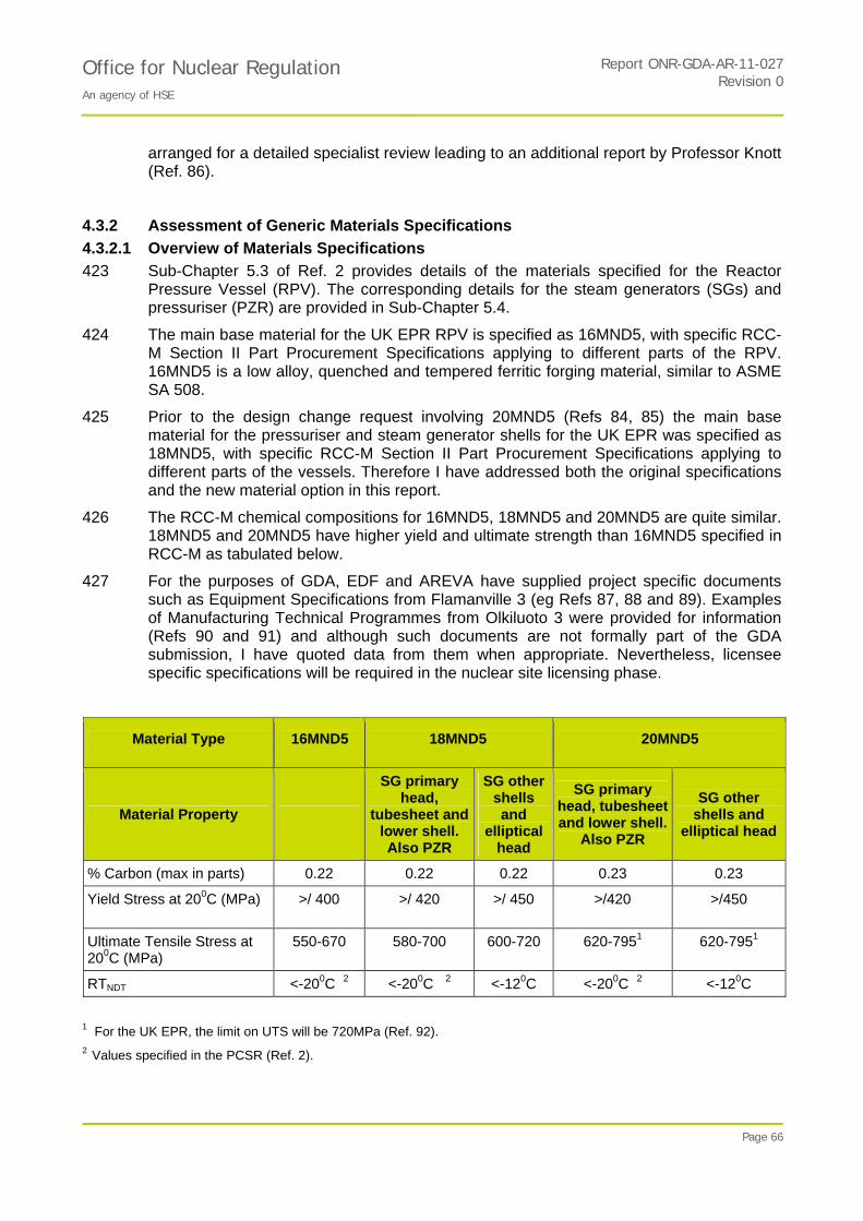
Office for Nuclear Regulation An agency of HSE
Report ONR-GDA-AR-11-027Revision 0
Page 66
arranged for a detailed specialist review leading to an additional report by Professor Knott (Ref. 86).
4.3.2 Assessment of Generic Materials Specifications
4.3.2.1 Overview of Materials Specifications
423 Sub-Chapter 5.3 of Ref. 2 provides details of the materials specified for the Reactor Pressure Vessel (RPV). The corresponding details for the steam generators (SGs) and pressuriser (PZR) are provided in Sub-Chapter 5.4.
424 The main base material for the UK EPR RPV is specified as 16MND5, with specific RCC-M Section II Part Procurement Specifications applying to different parts of the RPV. 16MND5 is a low alloy, quenched and tempered ferritic forging material, similar to ASME SA 508.
425 Prior to the design change request involving 20MND5 (Refs 84, 85) the main base material for the pressuriser and steam generator shells for the UK EPR was specified as 18MND5, with specific RCC-M Section II Part Procurement Specifications applying to different parts of the vessels. Therefore I have addressed both the original specifications and the new material option in this report.
426 The RCC-M chemical compositions for 16MND5, 18MND5 and 20MND5 are quite similar. 18MND5 and 20MND5 have higher yield and ultimate strength than 16MND5 specified in RCC-M as tabulated below.
427 For the purposes of GDA, EDF and AREVA have supplied project specific documents such as Equipment Specifications from Flamanville 3 (eg Refs 87, 88 and 89). Examples of Manufacturing Technical Programmes from Olkiluoto 3 were provided for information (Refs 90 and 91) and although such documents are not formally part of the GDA submission, I have quoted data from them when appropriate. Nevertheless, licensee specific specifications will be required in the nuclear site licensing phase.
Material Type 16MND5 18MND5 20MND5
Material Property
SG primary head,
tubesheet and lower shell. Also PZR
SG other shells and
elliptical head
SG primary head, tubesheet and lower shell.
Also PZR
SG other shells and
elliptical head
% Carbon (max in parts) 0.22 0.22 0.22 0.23 0.23
Yield Stress at 200C (MPa) >/ 400 >/ 420 >/ 450 >/420
>/450
Ultimate Tensile Stress at 200C (MPa)
550-670 580-700 600-720 620-7951 620-7951
RTNDT <-200C 2 <-200C 2 <-120C <-200C 2 <-120C
1 For the UK EPR, the limit on UTS will be 720MPa (Ref. 92). 2 Values specified in the PCSR (Ref. 2).

Office for Nuclear Regulation An agency of HSE
Report ONR-GDA-AR-11-027Revision 0
Page 67
4.3.2.2 Forging Processes (16MND5, 18MND5 and 20MND5)
428 There have been several rounds of comments and questions based on the original report from Professor Knott (Ref. 82) produced during Step 3 of the GDA. In the final report (Ref. 83) the various sets of comments by EDF and AREVA, responses to Technical Queries and feedback from Professor Knott are incorporated using colour coding to identify the authorship.
429 The quality of the response (Ref. 96) and the supporting references from EDF and AREVA (102,150,151 and152) provides confidence that they have a good understanding of the chemical compositions, processing, fabrication, heat-treatment and properties of their materials.
430 Valuable clarification was provided by additional references relating to segregation bands in ingots, with particular reference to local increases in carbon equivalent and the incidence of (cold) under-clad cracking, induced by hydrogen.
431 The forging qualification documents provided (for information purposes) in response to TQ-EPR-881 (Refs 90, 91, 93) demonstrate that the forging operations are specified in considerable detail. Questions raised about the amount of ‘cropping’, the use of ‘hot-top’ compounds, and forging reductions have been fully resolved.
432 In the EDF and AREVA responses, note was made of the possible use of hollow ingots (excluding the nozzle ring, which is too large to be made by this route). There are technical gains to be made in that the material at the (irradiated) inner wall of the subsequently forged RPV shell is free from segregates. I am satisfied that, with the controls exercised by EDF and AREVA, either solid or hollow forgings are acceptable.
433 The response to TQ-EPR-955 confirmed that the RPV belt-line weld is made by welding the bottoms of two forgings together so that the cleanest regions are used for the zone of highest irradiation. This is illustrative of the thought that EDF and AREVA have put into their manufacturing procedures.
434 In response to a further query (TQ-EPR-1315) on cropping and on the location of the prolongation in hollow forgings required for extraction of test specimens, EDF and AREVA explained their procedures in more detail. Checks are performed to ensure that segregated areas are avoided on the inner surfaces of the forgings where cladding will be applied. They have also provided a justification that the properties of specimens taken from a prolongation at the bottom of the forgings will be representative of the forging as a whole. This includes a pragmatic consideration of the possibility of minor, localised variations in properties and I consider the justification to be acceptable.
435 I agree with the judgement in Ref. 83 that the steelmaking and forging practices for EPR are appropriate and represent good, modern practice.
436 One caveat noted in Ref. 83 is that much of the quality of the ‘down-stream’ processing relies on the provision of clean, high-quality steel. The choice of a competent steelmaker, having the ability to comply with the detailed EDF and AREVA specifications, is then an important feature of quality-assurance. This is Assessment Finding AF-UKEPR-SI-23.
4.3.2.3 Materials Specifications for Main Vessel Forgings (especially RPV Forgings in 16MND5)
4.3.2.3.1 Chemical Composition
437 During GDA Step 4, EDF and AREVA have clarified that the detailed material compositions for the main forgings, although based on the Part Procurement
Office for Nuclear Regulation An agency of HSE
Report ONR-GDA-AR-11-027Revision 0
Page 68
Specifications in RCC-M, are more specific in the relevant Equipment Specifications. For certain elements the Equipment Specifications for the RPV, SGs and PZR (Refs 87,88,89 for Flamanville 3) are more restrictive, and my assessment takes these variations into account. I have summarized the compositions specified for the RPV forgings in Table 4. For comparison, I have also included the values specified for Sizewell B (Ref. 94) which were derived from ASME SA 508 Class 3 and are referred to here as UK usage or UK508. (Specifications for SG and PZR forgings in 18MND5 and 20MND5 are listed in Table 5 and discussed in Section 4.3.3.2.)
438 The Manufacturing Technical Programs (Refs 90 and 91) and the M140 Part Qualification report (Ref. 93) provided to support the response to TQ-EPR-881 refer to Olkiluoto 3. They illustrate the attention to detail in such documents which expand on the requirements in equipment specifications. For example Ref. 91 specifies limits on arsenic (As), tin (Sn), tantalum (Ta) and nitrogen (N) and Ref. 93 shows that nitrogen was within specification and the actual levels of As, Sn and Ta were well below the limits.
439 In Ref. 83 Professor Knott includes detailed discussion of the composition of the main forgings and the effects of the different elements on properties. I have also sought further specialist advice from NNL on the implications for irradiation embrittlement of the more detailed evidence on materials compositions which has become available during Step 4 (Ref. 95).
440 The main points, which also take account of my own sampling of Equipment Specifications and Manufacturing Technical Programmes, are summarised below. The base numbers for this discussion are derived from RCC-M 2007 (2008 Addendum for 20MND5) but various other specifications are also given for comparison in Tables 4 and 5.
441 Carbon (C): The maximum values for carbon content for parts (ie forgings) in 16MND5 and 18MND5 are both specified in RCC-M as 0.22%C, whereas the upper limit for 20MND5 is 0.23%. More detailed project-specific documents may also specify target values for the composition. For example, 16MND5 typically has a target value in the range 0.15-0.18%C whilst 18MND5 has a typical target value in the range 0.17-0.21%C (Ref.96). I concur with Professor Knott’s judgement that these limits and target values are acceptable. Carbon content of 20MND5 is discussed further in Section 4.3.3.2 below.
442 Chromium (Cr): As part of the general assessment of the propensity for stress relief cracking, Cr is one of the elements to consider. Cr improves the quenchability of 16MND5 and the value is related to the target value for C. The increase from 0.15% Cr in previous UK usage of SA508 Class 3 (referred to here as UK508) to a maximum of 0.25% Cr in 16MND5 in RCC-M is not regarded as significant.
443 Hydrogen (H): A low hydrogen level is needed to prevent hydrogen defects. Although not specified in RCC-M, rules in the Technical Manufacturing Programs restrict hydrogen to 1.5 ppm in the ladle or before degassing. This gives 0.8 ppm in the final product and is judged acceptable. (UK508 specified 1ppm).
444 Calcium (Ca): This is a consequence of the steelmaking process (Phosphorus and sulphur removal; de-oxidation) and cannot be considered as an element to control in isolation although low Ca may be an indicator of good removal of phosphorus and sulphur as slag.
445 Silicon (Si): This is also a consequence of the steelmaking process and there are no significant differences between the specifications of 16MND5, 18MND5 and UK508.
446 Antimony (Sb), arsenic (As) and tin (Sn): these are not specified in RCC-M or the Equipment Specifications, but EDF and AREVA expect the values to be below the UK508
Office for Nuclear Regulation An agency of HSE
Report ONR-GDA-AR-11-027Revision 0
Page 69
limits. The control is basically made by scrap selection. However, the Manufacturing Technical Programs sometimes specify limits on such residual elements and, for example, Ref. 91 specifies limits on tin, arsenic and tantalum.
447 Boron (B), titanium (Ti) and nitrogen (N): these are regarded simply as residual elements. There are no explicit limits in RCC-M or the Equipment Specifications but a limit on nitrogen may be specified in the Manufacturing Technical Program for the RPV (eg Ref. 91).
448 Sulphur (S): low sulphur content (0.005 % max) is required by the SG and PZR equipment specifications – as well as by that for the RPV. This is a desirable low level which is an improvement on RCC-M and UK508 and significantly better than ASME SA508 and should be beneficial for the upper shelf toughness.
449 Phosphorus (P): This is limited to 0.008% in the RPV, SG and PZR forgings and should help to reduce irradiation embrittlement and the propensity to reheat or underclad cracking. The lower phosphorus also helps to reduce thermal embrittlement which is especially beneficial in the PZR. This limit in RCC-M is an improvement on UK508 limits for SGs and PZR and significantly better than ASME SA508 for RPV, SGs and PZR.
450 Nickel (Ni): The range in RCC-M for 16MND5 and 18MND5 is 0.5-0.8% compared with 0-4-1.0% in UK508, and I agree with Professor Knott’s judgement that this range is appropriate. Ni also affects the rate of irradiation embrittlement, so the level in the beltline region of the RPV is important but this aspect is discussed under irradiation effects in Section 4.4.2.2 below.
451 Copper (Cu): This is limited in RCC-M to 0.08% in the belt-line region of the RPV as in UK508. Restrictions to RCC-M have been imposed elsewhere in the Equipment Specifications (see Tables 4 and 5) with limits of 0.10% in the rest of the RPV and the PZR and 0.12% in the SGs. The belt-line weld metal is limited to 0.07% Cu as in UK508. Recent advice from NNL (Ref. 95) confirms the benefits of the tighter controls on Cu in the beltline forgings and welds; there are significant reductions in the predicted shifts in RTNDT. As a result I judge that these Cu limits are appropriate.
452 I consider that the chemical compositions defined in the RCC-M Part Procurement Specifications and the example Equipment Specifications for the main forgings are generally appropriate, but where such documents do not indicate compositional limits for certain elements these should also be defined and justified by a future licensee in the site-specific Equipment Specification or related documentation.
453 In the case of RPV forgings made from 16MND5, Table 4 provides a comparison of relevant specifications which should be taken into account. Table 5 covers the SG and PZR forgings in 18MND5 and 20MND5 which are also discussed later in Section 4.3.3. Compositional limits for the elements in the tables should be specified and justified by a future Licensee in site specific documentation, taking due account of the precedents listed. This is Assessment Finding AF-UKEPR-SI-24.
4.3.2.3.2 Mechanical Properties
454 Professor Knott also reviewed the main mechanical properties which are specified in Sub-Chapters 5.3 and 5.4 of Ref. 1. For the RPV and most of the SG and PZR forgings the requirements are:
KV (0oC) > 80J average, > 60J individual value.
Upper shelf energy > 130J.

Office for Nuclear Regulation An agency of HSE
Report ONR-GDA-AR-11-027Revision 0
Page 70
455 RTNDT < -20oC.
456 Ref. 96 clarified that these requirements also apply to the transverse direction.
457 These specified figures are considered to be satisfactory; the RTNDT values are now comparable with, or better than, those for UK508 and the KV requirements at 00C are now such that values for all forgings, whether longitudinal or transverse, have to meet what were originally beltline longitudinal figures.
4.3.2.4 RPV Weld Metal Compositions
458 Table 4 lists the RCC-M specifications for submerged arc welds in the beltline and elsewhere.
459 The upper limit on nickel content in weld metal is 1.2% according to RCC-M which is higher than that specified for parent material. Since this has potential implications for irradiation embrittlement of beltline welds in the RPV, I requested further information which was supplied by EDF and AREVA in response to TQ-EPR-1362. In practice, AREVA records show that the Ni content in RPV welds never exceeds 0.85% (although it is noted that the RPV for Olkiluoto 3 fabricated in Japan has a Ni content of 0.89% in the welds). I also note that ASME III specifies an upper level of Ni of 0.85% for beltline welds. For these reasons I judge that it is reasonably practicable to set the maximum Ni level below that specified in RCC-M. This is Assessment Finding AF-UKEPR-SI-25.
4.3.2.5 Welding and Cladding of the Main Forgings Manufactured from 16MND5, 18MND5 (and 20MND5)
460 Ref. 97 discusses a range of metallurgical defects which can occur when welding and cladding pressure vessel steels, with particular emphasis on the causes of reheat (stress relief) cracking and hydrogen (cold) cracking. As a result of problems which occurred in the late 70s, there is now better understanding and control of segregated regions of high carbon equivalent (as discussed above) and welding procedures have been improved and provisions are taken to avoid the risks of reheat or hydrogen cracking.
461 As an example of refinements to welding procedures, Ref. 98 (EET DC 118, Revision C) describes requirements, supplementary to those in RCC-M, to limit the risks of cold-cracking and reheat cracking in welding and cladding of large forgings and summary tables for the conditions are given below. For completeness I have included the values for 20MND5 here, but these are discussed in more detail in Section 4.3.3.3.
Main Welds: Summary of Conditions Specified in EET DC 118, Revision C
Material Pre-heat
Interpass (low alloy weld metal and austenitic)
Interpass (nickel alloy)
Post-heat
16MND5 1500C 2500C 2250C 2000C for 2 hours
16MND5 RPV 1750C
1500C 2500C 2250C 2000C for 2 hours
1750C 2500C 2250C 2000C for 2 hours

Office for Nuclear Regulation An agency of HSE
Report ONR-GDA-AR-11-027Revision 0
Page 71
Cladding (automated): Summary of Conditions Specified in EET DC 118 Rev C
Material Pre-heat
Interpass (low alloy weld metal and austenitic cladding)
Interpass (nickel alloy)
Post-heat
16MND5 1500C 2500C 2250C 2000C for 2 hours
16MND5
18MND5 1500C 2500C 2250C 2000C for 2 hours
18MND5 SG tubesheet
1600C 2500C 2250C 2500C for 4 hours
20MND5 1600C 2500C 2250C 2000C for 2 hours
NB. 1. Pre-heat and post-heat values are minima. Inter-pass values are maxima.
2. Post-heat for RPV nozzles and flange, SG tubesheet, SG steam outlet nozzle is 2500C for 4 hours.
3. Manual cladding has the same controls for initial layers, but in certain specified circumstances the pre-heat may be relaxed for manual repairs to cladding.
462 For the EPR the manufacturing inspections of the main welds, performed after the post weld heat treatment, should provide a valuable check that significant reheat or hydrogen cracks have not occurred in the main welds. For the UK EPR such inspections are qualified and hence there is increased confidence in their capability to detect such defects.
463 When I asked for evidence that underclad hydrogen cracks are avoided (TQ-UKEPR-1361), EDF and AREVA explained that the only routine checks during manufacture for the absence of underclad cracks are those performed during the Welding Procedure Qualification and that no underclad cracks have been found during such tests since the introduction of the controls described in Ref. 98.
464 In practice, there is valuable evidence of the absence of underclad cracking for both 16MND5 and 18MND5. For Olkiluoto 3 the client required 100% ultrasonic examination of the cladding of the RPV, steam generators and pressuriser (except where the cladding is >12mm thick or the radius of curvature <25mm) and no underclad crack indications were found. The steam generators and pressurisers were manufactured from 18MND5 and the RPV from 16MND5.
465 Similarly, no indications were observed during additional manufacturing ultrasonic inspection for underclad cracks in the RPV core zone of Flamanville 3 which is constructed from 16MND5.
466 In-service inspection of RPVs in France (manufactured from 16MND5) includes an ultrasonic inspection for underclad cracks in the core region and no such cracks have been detected on plant for which the specific manufacturing measures to avoid cracking have been applied.

Office for Nuclear Regulation An agency of HSE
Report ONR-GDA-AR-11-027Revision 0
Page 72
467 Ref. 98 covers cladding and buttering with austenitic steel, but it does not appear to discuss dissimilar metal ‘safe-end’ welds specifically. The dissimilar metal welds for the RPV, SG and PZR are made by a TIG narrow gap welding process using Alloy 52 (Ni-Cr-Fe) filler material without any buttering. The welding procedures for ‘safe ends’ are discussed in Section 4.6.2 below.
468 Professor Knott comments (Ref. 83) that whether or not there is likely to be a risk of cracking with safe end welds depends on the design of the nozzle and the geometrical distribution of any segregated regions associated with it.
469 I conclude that the welding precautions introduced in the 1980s after the discovery of reheat and hydrogen cracking appear to be adequate to avoid the occurrence of such cracking in 16MND5 and 18MND5. Nevertheless, in compliance with SAP EMC.17 and Paragraph 252 (Ref. 5), I recommend that sample inspections for underclad cracking should be carried out during manufacture. This is Assessment Finding AF-UKEPR-SI-26.
4.3.2.6 Conclusions and Findings Relating to the Main Vessel Forgings
470 EDF and AREVA have demonstrated that they have a good understanding of the chemical compositions, processing, fabrication, heat-treatment and properties of their materials.
471 The chemical compositions defined in the example Equipment Specifications and Manufacturing Technical Programs for the main forgings are appropriate and need to be reflected in the project specific documents along with additional limits on residual elements.
472 Because of the potential implications for irradiation embrittlement of beltline welds in the RPV, the maximum value of nickel content in beltline welds should be limited
473 The welding precautions introduced in the 1980s after the discovery of reheat and hydrogen cracking appear to be adequate to avoid the occurrence of such cracking in 16MND5 and 18MND5. Nevertheless, as a prudent measure, I recommend that sample inspections for underclad cracking should be carried out during manufacture. The selected zones should include a sample of the core region which is inspected in-service and of the cladding associated with the safe end welds.
474 I have rasied four Assessment Findings are raised in this area:
AF-UKEPR-SI-23: The Licensee shall check the competence of steelmaker(s) to comply with the RCC-M M140 qualification requirements for specific components before placing contracts for forgings.
AF-UKEPR-SI-24: The Licensee shall ensure that, since the RCC-M Part Procurement Specifications for the main vessel forgings do not provide an adequate control on the composition for all elements, additional limits on composition are specified and justified which take account of the relevant precedents specified in Tables 4 and 5 of this report.
AF-UKEPR-SI-25: The licensee shall ensure that the maximum value of nickel content in beltline welds is restricted, either by setting an upper limit not exceeding 0.85% Ni or by setting a target value with a rigorous process for reviewing the acceptability of the Ni value should the actual value be above 0.85%.
AF-UKEPR-SI-26: The Licensee shall ensure that sample ultrasonic inspections for underclad cracking are performed during manufacture of the RPV, SGs and PZR.

Office for Nuclear Regulation An agency of HSE
Report ONR-GDA-AR-11-027Revision 0
Page 73
475 Assessment Findings AF-UKEPR-SI-23 and AF-UKEPR-SI-24 shall be completed before ordering long lead items, and is linked to the generic milestone of long lead item and SSC procurement specifications. This is because it would be extremely difficult to make any changes to the forgings once they have been manufactured, and that could lead to substantial delays and additional costs.
476 Assessment Findings AF-UKEPR-SI-25 and AF-UKEPR-SI-26 shall be completed before the generic milestone of RPV installation. This is because it would be extremely difficult to make any substantive changes once the components start to be installed which could then lead to substantial delays and additional costs.
4.3.3 Review of the Proposal to Introduce 20MND5 as an Option for Steam Generator and Pressuriser Shells
4.3.3.1 Background to Design Change UKEPR-CMF-017
477 In Design Change Management Form UKEPR-CMF-017 (Ref. 85) it is proposed to extend the range of material choice for the steam generators and the pressuriser to the 20MND5 grade, in addition to the existing 18MND5 grade. 20MND5 grade has been introduced in RCC-M 2008 via the Modification Sheet FM 1060 (December 2007). These steel grades are low alloy steel types and the chemical compositions are listed in Table 2.
478 My assessment included review of two reports supplied by EDF and AREVA (Refs 99, 100) and responses to TQ-EPR-1138 and TQ-EPR-1361. In addition to my own assessment, I have arranged for a detailed specialist review leading to an additional report by Professor Knott (Ref. 86). ND also requested that EDF and AREVA should seek an Independent Nuclear Safety Assessment (INSA) from an external organisation.
479 The INSA report was received from EDF and AREVA on 12 July 2011 (Ref. 101) and it raises no issues which were judged by the INSA assessor to be significant. I have reviewed the INSA report and I am satisfied that the queries mostly relate to presentation and consistency of information and there are none which would cause me to change my assessment of the proposal to introduce 20MND5.
480 One of the questions in TQ-EPR-1138 queried the extent of previous use of 20MND5 material for other plant especially for components which have cladding. This is because of the concern with cladding materials with high carbon equivalent in segregated bands and the risk of hydrogen-induced cold-cracking. All the ferritic forgings in contact with the primary coolant have austenitic cladding. Hence the pressuriser and steam generator channel head, tubesheet and divider plate are clad, but the steam generator secondary side is not clad.
481 The EPRs at Flamanville 3 and Olkiluoto 3 used 18MND5 for the steam generators and pressuriser. The first use of 20MND5 for EPR plant is believed to be the steam generators (both primary and secondary sides) for Taishan 1 and 2 but not the pressuriser. These components have involved cladding 20MND5 where it forms part of the primary circuit pressure boundary.
482 Note that an earlier version of 20MND5, was used extensively for the secondary (unclad) forgings of the 80 steam generators equipping 20 four-loop 1300MWe French reactors.

Office for Nuclear Regulation An agency of HSE
Report ONR-GDA-AR-11-027Revision 0
Page 74
4.3.3.2 Chemical Composition and Mechanical Properties of 20MND5 Forgings
483 Other than where indicated below the conclusions and findings for 16MND5 and 18MND5 apply. With respect to chemical composition, the main points from Ref. 86, 99 and 100 are discussed below.
484 The maximum carbon content, which is slightly higher for 20MND5 compared with 18MND5, improves tensile properties by perhaps 10 to 20 MPa. The maximum specified content for carbon in forgings is equal to 0.22% for 18MND5 and 0.23% for 20MND5. However the measured mean values (Ref. 100 Table 4) are lower– 0.181% for 18MND5 and 0.202% for 20MND5.
485 The maximum measured values for C in Ref. 100 are the same for both 20MND5 and 18MND5 at 0.22%, although I note that the sample size is considerably smaller for the 20MND5 measurements (96 cf. 322). Indeed, similar trends are observed in the other histograms of chemical composition and mechanical properties in Ref. 100 and the properties of 20MND5 forgings could be regarded as lying within the usual spread which occurs for 18MND5 but with tighter control of composition and properties for 20MND5.
486 The range specified for the nickel content is broader than that for 16 MND5 or 18MND5: a range of 0.4 - 1.0% contrasted with 0.5 - 0.8%. The higher nickel will increase hardenability and, combined with the higher carbon level the increased hardness in the HAZ will increase susceptibility to under-clad cracking (Ref. 83) so that more care may need to be taken to avoid HAZ or under-clad cracking (see below).
487 When I queried the upper limit on Ni, EDF and AREVA explained that 20MND5 is derived from the equivalent US Standard A 508 Grade 3 Cl 2 for which the required nickel content range is 0.4-1.0%. However, in the corresponding Manufacturing Technical Program the Nickel target value for both 18MND5 and 20MND5 is set at about 0.75% (TQ-UKEPR-1138 Reply to Question 3). I agree that this is a satisfactory position, if a similar restriction is set for the nickel content of 20MND5 for the UK EPR. This is Assessment Finding AF-UKEPR-SI-27.
488 Ref. 100 shows in a number of areas that tighter control than in the past is now being achieved on both chemical compositions and mechanical properties. Consequently one should be cautious about comparing earlier forgings of a given specification with today’s production. For example, the figure for nickel measured on earlier forgings (Ref. 99, Fig 3) is 0.93% whereas the value for recent forgings made for Taishan (Table 4) is 0.715% which is much closer to the ‘target” 0.75% described in the reply. The steam generator and pressuriser are not subjected to neutron irradiation, so there are no consequences for embrittlement as there might be for the RPV.
489 Professor Knott had already reviewed the toughness properties for 16MND5 and 18MND5 specified in the PCSR and concluded that these were acceptable (Ref. 82). For the RPV and most of the SG and PZR forgings the requirements are:
KV (0oC) > 80J average, > 60J individual value.
Upper shelf energy > 130J.
RTNDT < -20oC.
490 Ref. 96 clarified that these requirements also apply to the transverse direction.
491 The heat treatment of such steel grades consists of quenching and tempering. The austenitisation temperatures of both 18MND5 and 20MND5 grades are equivalent. The required nominal tempering temperature of the 18MND5 grade is between 635°C –

Office for Nuclear Regulation An agency of HSE
Report ONR-GDA-AR-11-027Revision 0
Page 75
665°C and that for 20MND5 is between 6300C - 660°C. The slight difference (5°C) permits a tensile strength gain of a few MPa and is considered acceptable (Ref. 86).
492 With these higher mechanical properties, resulting from chemical composition and heat treatment, the minimum tensile strengths are 3 to 7% higher for 20MND5 than are those for 18MND5. This means that 20MND5 can offer somewhat higher margins in the design of the steam generator and the pressuriser.
493 In considering the introduction of 20MND5 steel, it is important to note a statement made in the letter from AREVA/EDF dated 8 July 2010 (Ref. 92). The statement is that “the UK EPR Equipment Specifications for the Steam Generator and Pressuriser will limit the Ultimate Tensile Strength at room temperature to 720MPa for 20MND5 parts”. This value is the same as the maximum for 18MND5 for the SG shells and elliptical heads and only 20MPa higher than for 18MND5 (700 MPa) for the tubesheet and primary head (Ref. 99 Table 2).
494 In terms of toughness, the specified Charpy values are the same for the two materials and those measured for 20MND5 compare well with those of 18MND5. Furthermore, both materials exhibit very good values of temperature transition RTNDT. The same ductility (≥20% elongation) is required for all 20MND5 components as that for those made from18MND5.
495 In summary, I judge that the specified values for these tensile and toughness properties of 20MND5 are appropriate because of the similarity to those for 18MND5, and the measured values available clearly exceed requirements by some margin.
496 Considering the small difference of carbon content between the 20MND5 and 18MND5 steel grade, the conditions of application of both grades are equivalent for forging and machining although welding and preheating temperature for welding might require procedural changes (see Section 4.3.3.3 below).
4.3.3.3 Welding and Cladding of Forgings Manufactured from 20MND5
497 As a result of problems which occurred in the late 70s, there is now better understanding and control of segregated regions of high carbon equivalent (as discussed in Section 4.3.2.4 above) and welding procedures have been improved so that the risks of reheat or hydrogen cracking are generally low.
498 As an example of refinements to welding procedures, Ref. 98 (EET DC 118) describes requirements, supplementary to those in RCC-M, to limit the risks of cold-cracking and reheat cracking in welding and cladding of large forgings and includes some specific constraints for 20MND5.
499 For the main welds, the preheat temperature for 20MND5 forgings is increased to 175oC, compared with 150oC for 18MND5 or 16MND5 and the inter-pass temperature (for all) as 250oC. The minimum post-heat treatment (‘bake-out’) is specified as a minimum of 2 hours at 200oC for all three materials.
500 One of the queries in TQ-EPR-1138 elicited the following response from EDF and AREVA: ‘Post heating is performed for eliminating excess hydrogen by diffusion; there is no reason that the hydrogen diffusion coefficient is lower for 20MND5 than for 18 and 16 MND5. It is why no difference on the post-heat treatment (temperature and time) is required and needed between 16, 18 or 20MND5.’
501 Although the hydrogen diffusion coefficient may not be altered, the target level of hydrogen after post-heat treatment may have to be lower, if the higher preheat

Office for Nuclear Regulation An agency of HSE
Report ONR-GDA-AR-11-027Revision 0
Page 76
temperature has not fully compensated for the higher hardenability (carbon equivalent) of 20MND5 compared with 16 or 18MND5. This is one of the reasons why I have recommended sample inspections to check that underclad cracks have not occurred (see AF-UKEPR-SI-28 below).
502 The post-heat conditions may be reasonable for large girth welds (in SG and PZR), in a situation where there is remnant heat in the steel, and where the hydrogen levels are low in both the parent material and the weld metal, but austenitic cladding is potentially more demanding as discussed below.
503 For cladding on 20MND5 forgings, the pre-heat temperature is increased to 1600C compared with the 1500C specified for most 18MND5 components. 1600C matches the condition specified for tubesheets in 18MND5 which, like thick section nozzles, have experienced underclad hydrogen cracking problems in the past (Ref. 102).
504 Faure et al (Ref. 102) conclude:
“Metallurgical assessment of underclad defects formed before stress relief treatment of Ni-Cr-Fe alloy-clad steam generator tube sheets and austenitic stainless steel-clad reactor vessel nozzles has made it possible to identify the cause of these defects: cold cracks formed in the segregation zones during deposition without pre-heating and post-heating of the second (and potentially successive) cladding layer/s.
This metallurgical analysis has led us to reinforce the pre- and post-heating conditions and to extend these to the deposition of all layers, thus enabling us to resolve the problem in question.”
505 Austenitic cladding of 20MND5 requires care to protect against the risk of hydrogen cracking because the cladding has a hydrogen content of order 15 ml/100g of metal. The hydrogen-induced under-clad cracking problem is potentially exacerbated in 20MND5, because the target C level is typically about 0.20% rather than typically 0.18% for 18MND5. The upper limit on Ni is also higher which will increase hardenability but this will also increase hardness in the HAZ and hence increase susceptibility to hydrogen-induced under-clad cracking. However, there may not be much difference between the two materials in practice because, as discussed in Section 4.3.3.2 above, Assessment Finding AF-UKEPR-SI-27 recommends an upper value of 0.8% Ni in 20MND5 which matches the limit for 18MND5.
506 EDF and AREVA state that the post-heat requirements for cladding depend on section thickness rather than material type (TQ-UKEPR-1138 Response 5a). For this reason tubesheets have an increased post-heat of 2500C for 4 hours whether they concern 18MND5 or 20MND5. They also point out that provisions are taken as far as possible to make cladding in areas free of segregated bands: bottom side of ingot for SG tube sheet and PZR heads and use of hollow ingot for PZR shells.
507 Both these precautions add confidence that the risk of underclad hydrogen cracking has been reduced. Recent production of 20MND5 forgings (Ref. 100) demonstrates a tighter distribution of carbon composition which is also encouraging; however the number of samples tested is very much less than that for 18MND5 or 16MND5.
508 I decided to explore the extent of any experimental evidence that the welding procedures for the main welds and particularly for cladding of 20MND5 components avoid the occurrence of cold cracking ie the pre-heat, inter-pass and post-heat are adequate?

Office for Nuclear Regulation An agency of HSE
Report ONR-GDA-AR-11-027Revision 0
Page 77
509 In response to TQ-UKEPR-1361 EDF and AREVA explained that the only routine checks during manufacture for the absence of underclad cracks are those performed during the Welding Procedure Qualification.
510 There is considerable evidence that underclad cracking has been avoided in components manufactured from 16MND5 and 18MND5 as discussed in Section 4.3.2.3 above.
511 The direct experimental evidence that underclad cracking has been avoided when cladding 20MND5 is limited to Taishan for which the steam generators are made of this material and the Welding Procedure Qualification indicates that no underclad cracking occurred. But I am not aware that any inspection for underclad cracking was performed on these components.
512 I conclude that the welding controls originally introduced in the 1980s after the discovery of reheat and hydrogen cracking and refined recently with the introduction of 20MND5 appear to be adequate to avoid the occurrence of such cracking in 16MND5 and 18MND5, but there is relatively little direct evidence for 20MND5. Consequently, in compliance with SAP EMC.17 and Paragraph 252 (Ref.5) I recommend that sample inspections for underclad cracking should be carried out during manufacture of components using 20MND5. This is Assessment Finding AF-UKEPR-SI-28.
513 In conclusion, I judge that this new material option, 20MND5, is acceptable for the proposed use for the following reasons:
1. The upper limit of 0.23%C for 20MND5 parts is a relatively small increase compared with the corresponding value for 18MND5 (0.22%).
2. For the forgings produced recently for Taishan with a target value of typically 0.20%C, the maximum measured value was 0.21%C which is within the allowed limit for 18MND5.
3. The upper limit on UTS is set at 720MPa which is similar to 18MND5.
4. I have recommended that the nickel content should be limited as discussed above (see AF-UKEPR-SI-27).
5. The qualified manufacturing inspections of the main welds, performed after the post weld heat treatment, should provide a valuable check that significant reheat or hydrogen cracks have not occurred in the main welds.
6. A sample inspection for underclad cracking will help to confirm that the manufacturing procedures have avoided such cracks.
4.3.3.4 Conclusions and Findings Relating to use of 20MND5 Forgings.
514 The new material option 20MND5 is acceptable for the proposed use, but the Ni value should be limited and sample non-destructive testing should be performed to check that underclad cracks are avoided. I have raised two assessment findings in this area.
AF-UKEPR-SI-27: The licensee shall ensure that the maximum value of nickel content in 20MND5 is restricted, either by setting an upper limit not exceeding 0.8% Ni or by setting a target value with a rigorous process for reviewing the acceptability of the Ni value should the actual value be above 0.8%.
515 This Assessment Finding shall be completed before procuring the long lead items and is linked to the generic milestone of long lead item and SSC procurement specifications. This is because it would be extremely difficult to make any changes to the forgings once

Office for Nuclear Regulation An agency of HSE
Report ONR-GDA-AR-11-027Revision 0
Page 78
they have been manufactured, and that could lead to substantial delays and additional costs.
AF-UKEPR-SI-28: The Licensee shall ensure that sample ultrasonic inspections for underclad cracking are performed during manufacture on all 20MND5 components which are clad. The sample should take account of the relative lack of evidence on avoidance of underclad cracking with this material.
516 This Assessment Finding shall be completed before the generic milestone of RPV installation, although in practice it will need to be completed earlier to suit the programme for manufacture of the vessels. This is because it would be extremely difficult to make any substantive changes once the components start to be installed which could then lead to substantial delays and additional costs.
4.4 Effects of Irradiation on RPV Cylindrical Shell and Circumferential Welds
4.4.1 Overview of Irradiation Embrittlement Issues
517 This is activity AR09060-5 from the Assessment Plan (Ref. 6) and is associated with RO-UKEPR-25.
518 As discussed in the Step 3 report (Ref. 8 Paras 197-247), neutron irradiation embrittlement is arguably the most significant ageing mechanism for PWR reactor pressure vessels. The effect of neutron irradiation on ferritic steels is a shift to higher temperatures the brittle to ductile fracture transition temperature. A high toughness transition temperature can mean the early phase of reactor start-up occurs with the temperature of the RPV metal (adjacent to the core) in the transition region. The same applies at the end of a shutdown sequence. ND SAPs EAD.1 to EAD.4 (Ref. 5) require arrangements for assessing such ageing effects and monitoring them during operation.
519 ND SAPs (Ref. 5) also consider ductile behaviour of reactor pressure vessels in EMC.23 and Para 268 which states that:
“a) clear safety benefits derive from operating on the upper shelf of the toughness transition curve;
b) RPVs must, for normal steady-state operation, operate on the upper shelf.”
520 Para 262 Item c) of the SAPs states that designs should consider avoiding welds in high neutron radiation locations.
521 The EPR design includes a weld in the RPV at core mid-height; however there is a heavy reflector outside the core but within the core barrel which substantially reduces the neutron dose on the RPV wall.
522 The PCSR (Ref. 1 Sub-Chapter 5.3 Section 3.1.1) states that an end-of-life integrated flux of around 1.26 x 10¹⁹ n/cm2 (E > 1 MeV) is reached under the following conditions:
60-year operating life with a load factor of 0.9.
An In-Out fuel management scheme, with UO2 fuel assemblies.
A core surrounded by a heavy reflector.
523 The In-Out fuel management scheme refers to the way fuel is added to, moved from inner to outer and removed from the reactor core once ‘equilibrium’ fuel management conditions have been achieved. This scheme results in part-used fuel being located on the outermost ring of the core which produces a lower flux of neutrons than newer fuel.

Office for Nuclear Regulation An agency of HSE
Report ONR-GDA-AR-11-027Revision 0
Page 79
The mean-free path of neutrons from the fuel is such that the neutron flux exiting the core barrel is dominated by the outermost fuel assemblies. The net effect of In-Out management is to reduce the neutron flux to the RPV, compared to fuel management schemes that result in new fuel at the periphery of the core.
524 From a presentation and discussion on 4 June 2008, EDF and AREVA confirmed the maximum end of life fluence of 1.26x10¹⁹ n/cm2 applies to the midline weld (Weld 1) with the lower shell to transition ring (Weld 3) at about 0.8x10¹⁹ n/cm2 and the upper shell to nozzle ring (Weld 2) at about 0.06x10¹⁹ n/cm2. It is worth noting that there is a strong circumferential variation of neutron fluence such that the majority of the inner surface experiences a dose notably less than the maximum.
525 The Step 3 assessment report (Ref. 8, Para. 213) considered that the design incorporating a midline weld with a heavy reflector was acceptable, but there were other questions raised about how irradiation embrittlement is to be adequately controlled in the RPV beltline forgings and welds, and particularly the effect of the heavy reflector on neutron energy spectrum.
526 The effect of the heavy reflector is to both reduce the neutron flux and to change the neutron energy spectrum. The water gap also modifies the neutron flux and energy spectrum such that at the RPV inner surface, the energy spectrum is similar to past PWRs and to the surveillance conditions which have been used to derive the dose-damage relationship. However the EPR surveillance specimens used to monitor progress of embrittlement in service might be subject to a somewhat different flux energy spectrum.
527 EDF and AREVA agreed (Ref. 103) to undertake analysis of neutron dose in terms of displacements per atom (dpa) to compare with the results based on neutrons per cm2 (n/cm2). The dpa calculations give a measure of the embrittlement anticipated as a result of the difference in flux energy spectrum between surveillance specimen locations and the RPV inner surface. This work was progressed during Step 4 and reported towards the end of 2010 (Ref. 104).
528 The chemical composition of the RPV beltline forgings and welds has a significant influence on the rate of embrittlement. Chemical composition has already been discussed more generally in Section 4.3 above, but this section concentrates on copper, phosphorus and nickel content which feature strongly in the dose-damage relationship used to predict irradiation embrittlement.
529 Because of the specialist nature of these issues, I arranged a small consultancy contract with NNL to review the dpa analyses and to provide an update on the implications of a few key changes to material compositions and dose estimates since their Step 3 review (Ref. 105) was issued. Their latest advice is reported in Refs 95, 106 and 107.
4.4.2 Step 4 Assessment
4.4.2.1 Summary of Safety Case for RPV Beltline Region
530 For the EPR RPV base materials, the RCC-M Part Procurement Specifications require a start of life RTNDT of less than or equal to -200C (Ref. 2, Sub-Chapter 5.3 Section 4.1). The PCSR also claims the end of life RTNDT will be no higher than +300C (i.e. a total shift of 500C, based on the RCC-M mean dose-damage correlation).
531 An In-Out fuel management plan is specified in the PCSR (Sub-chapter 5.3 Sect 3.1.1). This represents a low leakage core arrangement and reduces the neutron dose to the RPV. However since some of the analyses of irradiation embrittlement have used values
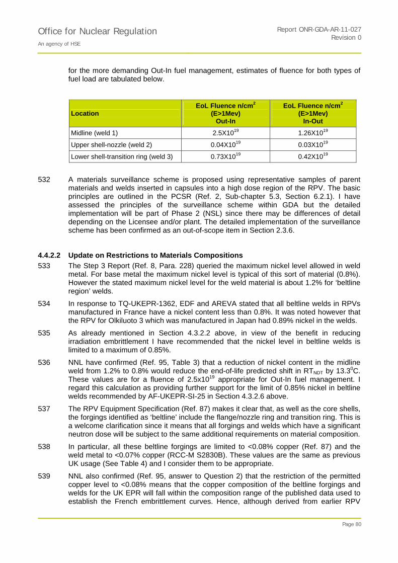
Office for Nuclear Regulation An agency of HSE
Report ONR-GDA-AR-11-027Revision 0
Page 80
for the more demanding Out-In fuel management, estimates of fluence for both types of fuel load are tabulated below.
Location EoL Fluence n/cm2
(E>1Mev) Out-In
EoL Fluence n/cm2 (E>1Mev)
In-Out
Midline (weld 1) 2.5X10¹⁹ 1.26X10¹⁹
Upper shell-nozzle (weld 2) 0.04X10¹⁹ 0.03X10¹⁹
Lower shell-transition ring (weld 3) 0.73X10¹⁹ 0.42X10¹⁹
532 A materials surveillance scheme is proposed using representative samples of parent materials and welds inserted in capsules into a high dose region of the RPV. The basic principles are outlined in the PCSR (Ref. 2, Sub-chapter 5.3, Section 6.2.1). I have assessed the principles of the surveillance scheme within GDA but the detailed implementation will be part of Phase 2 (NSL) since there may be differences of detail depending on the Licensee and/or plant. The detailed implementation of the surveillance scheme has been confirmed as an out-of-scope item in Section 2.3.6.
4.4.2.2 Update on Restrictions to Materials Compositions
533 The Step 3 Report (Ref. 8, Para. 228) queried the maximum nickel level allowed in weld metal. For base metal the maximum nickel level is typical of this sort of material (0.8%). However the stated maximum nickel level for the weld material is about 1.2% for ‘beltline region’ welds.
534 In response to TQ-UKEPR-1362, EDF and AREVA stated that all beltline welds in RPVs manufactured in France have a nickel content less than 0.8%. It was noted however that the RPV for Olkiluoto 3 which was manufactured in Japan had 0.89% nickel in the welds.
535 As already mentioned in Section 4.3.2.2 above, in view of the benefit in reducing irradiation embrittlement I have recommended that the nickel level in beltline welds is limited to a maximum of 0.85%.
536 NNL have confirmed (Ref. 95, Table 3) that a reduction of nickel content in the midline weld from 1.2% to 0.8% would reduce the end-of-life predicted shift in RTNDT by 13.30C. These values are for a fluence of 2.5x10¹⁹ appropriate for Out-In fuel management. I regard this calculation as providing further support for the limit of 0.85% nickel in beltline welds recommended by AF-UKEPR-SI-25 in Section 4.3.2.6 above.
537 The RPV Equipment Specification (Ref. 87) makes it clear that, as well as the core shells, the forgings identified as ‘beltline’ include the flange/nozzle ring and transition ring. This is a welcome clarification since it means that all forgings and welds which have a significant neutron dose will be subject to the same additional requirements on material composition.
538 In particular, all these beltline forgings are limited to <0.08% copper (Ref. 87) and the weld metal to <0.07% copper (RCC-M S2830B). These values are the same as previous UK usage (See Table 4) and I consider them to be appropriate.
539 NNL also confirmed (Ref. 95, answer to Question 2) that the restriction of the permitted copper level to <0.08% means that the copper composition of the beltline forgings and welds for the UK EPR will fall within the composition range of the published data used to establish the French embrittlement curves. Hence, although derived from earlier RPV

Office for Nuclear Regulation An agency of HSE
Report ONR-GDA-AR-11-027Revision 0
Page 81
designs, these curves should be a reliable indicator of irradiation damage in the UK EPR. However there is a caveat to this conclusion relating to nickel: since the nickel content in weld metal may be as high as 0.89% (See Section 4.3.2.4) this level is at the upper end of the composition range used to derive the dose-damage relationship.
4.4.2.3 Update on Dose-damage Relationships
540 I asked NNL for an expert opinion on the extent to which the hardening effects due to irradiation, thermal ageing and strain ageing should be additive. RCC-M adopts the approach that they are not, and the shift in RTNDT is simply the largest of the three values predicted independently.
541 NNL explained (Ref. 107, answer to question 4), that thermal ageing is likely to be very slow for temperatures typical of the RPV beltline (~3000C and below). Long-term ageing tests have shown no significant ageing-induced changes in the mechanical properties of base or weld metal at 3000C. Similarly, strain-ageing effects for the beltline region are expected to be small.
542 Consequently I judge that the RCC-M approach of not regarding the separate mechanisms as cumulative is pragmatic and reasonable for the RPV belt-line forgings and welds. Irradiation hardening is likely to dominate the observed rate of embrittlement.
543 Although thermal ageing is not likely to be very significant for the RPV belt-line forgings, it could be significant at higher temperatures such as those experienced by the RPV outlet nozzles and the pressuriser. I would expect a future Licensee to have access to an adequate database on thermal ageing effects and this may require a thermal ageing surveillance programme for materials operating at higher temperatures. This is Assessment Finding AF-UKEPR-SI-29.
4.4.2.4 Review of DPA Calculations
544 EDF and AREVA have evaluated the displacements per atom (dpa) experienced by the EPR RPV and surveillance capsules during service (Ref. 104). The calculations are based on a particular core loading which assumes In/Out fuel management in line with the PCSR (Sub-Chapter 5.3, Section 4.2) but are performed both for the EPR design with a heavy reflector as well as a standard PWR design.
545 Ref. 104 presents results for neutron flux and dpa (in each case as a function of neutron energy) for the inner surface of the RPV wall and for the locations of two of the surveillance capsules. They have used widely accepted 2D neutronics codes, DORT and MCNP. In the DORT code the nuclear data are averaged over broad energy ranges, so these calculations are benchmarked against the predictions of a more refined Monte Carlo code, MCNP that uses a very detailed neutron group structure.
546 The results are presented in terms of three energy ranges:
High energy neutrons E>1MeV.
Epithermal neutrons 5.53 keV < E < 1 MeV.
and thermal neutrons E < 5.53 keV.
547 The results confirm that the neutron energy distribution at the RPV are largely unchanged when a heavy reflector is used rather than a water reflector. This implies that the dose-damage relationships (RCC-M, FIS/EDFs) developed from data obtained with reactors
Office for Nuclear Regulation An agency of HSE
Report ONR-GDA-AR-11-027Revision 0
Page 82
using water reflectors should still be applicable for predicting irradiation damage in the RPV of the EPR.
548 However the dpa analyses for the surveillance capsules have important implications. The dpa rates in the surveillance samples are dominated by damage from epithermal neutrons whereas the RPV dpa values are dominated by the damage from high energy neutrons. Consequently, I believe this difference in neutron energy spectra between the surveillance capsules and the RPV must be properly taken into account to design the surveillance scheme and interpret the results.
549 I am not yet satisfied that it would be valid to relate damage measured in the surveillance capsules to damage predicted in the RPV wall using an approach based on high energy neutrons (E>1MeV) alone. Since this approach is currently proposed in the PCSR (Ref. 2 Chapter 5.3) it will need to be assessed fully. I have raised a GDA Issue GI-UKEPR-SI-02 to progress this. I believe that it is feasible to resolve but the approach needs to be agreed before I could support a full DAC.
550 I asked NNL to review the overall approach used for these predictions and to comment on their implications and they have raised several comments about the dpa analyses (Ref. 106).
551 NNL have confirmed that it would be highly conservative to relate damage in the surveillance specimens to damage in the RPV using an approach based on >1MeV neutrons because the measured damage in the surveillance specimens would be significantly greater than would be expected based on the >1MeV fluence. Such an approach would also lead to concerns about the high lead factors (Anticipation Factors) involved.
552 One comment is that, since the predicted Anticipation Factors based on dpa are now significantly higher than those predicted previously based on high energy neutrons, the withdrawal schedule for the capsules may need to be revised so that suitable specimens will still be available for withdrawal later in reactor life.
553 A second comment concerns the dependence of embrittlement rates on the neutron energy spectra. Because of the way in which recoils of lattice atoms are treated, the methodology employed by EDF and AREVA, although internationally accepted, may produce incorrect relative dpa levels for samples irradiated in locations with very different neutron energy spectra, when that difference lies in the thermal:fast neutron ratio.
554 Another comment is whether the higher fluxes of thermal neutrons at the current surveillance capsule location with the heavy water reflector implies higher fluxes of gamma radiation in the surveillance samples. If so this might lead to gamma heating of the samples with consequences for the rate of embrittlement.
555 If the principle of using dpa analyses for the surveillance scheme were to be accepted by EDF and AREVA, then I believe the other issues relating to the dpa analysis methodology could be taken forward as Assessment Findings.
4.4.3 Conclusions and Findings Relating to Irradiation Damage
556 The composition of the beltline forgings and welds for the UK EPR will fall within the composition range of the published data used to establish the French embrittlement curves. Hence, although derived from earlier RPV designs, these curves should be a reliable indicator of irradiation damage in the UK EPR.
Office for Nuclear Regulation An agency of HSE
Report ONR-GDA-AR-11-027Revision 0
Page 83
557 Limiting the maximum Ni level in belt-line welds to 0.85% (as recommended by AF-UKEPR-SI-25) will have a beneficial effect on the end-of-life irradiation shift.
558 The RCC-M approach of not regarding the separate hardening mechanisms as cumulative is pragmatic and reasonable for the RPV belt-line forgings and welds. Irradiation hardening is likely to dominate the observed rate of embrittlement. However thermal ageing may be significant for forgings operating at higher temperatures, and I have rasied the following Assessment Finding:
AF-UKEPR-SI-29: A Licensee shall have access to an adequate database so that thermal ageing effects can be reliably predicted and, if necessary, a thermal ageing surveillance programme should be established for materials operating at temperatures experienced by the RPV outlet nozzles and the pressuriser.
559 This shall be completed before the generic milestone of install RPV because it would be extremely difficult to make any substantive changes once the components start to be installed which could then lead to substantial delays and additional costs.
560 The dose-damage relationships (RCC-M, FIS/EDFs) developed from data obtained with reactors using water reflectors should still be applicable for predicting irradiation damage in the RPV of the EPR which has a heavy reflector.
561 I am not yet satisfied that it would be valid to relate damage measured in the surveillance capsules to damage predicted in the RPV wall using an approach based on high energy neutrons (E>1MeV) alone. Analysis using dpa may be required to design the surveillance scheme and interpret the results. I have raised GDA Issue GI-UKEPR-SI-02 to take this forward before closure of GDA.
GI-UKEPR-SI-02: The principles of the surveillance scheme shall adequately take account of the implications of the change in neutron energy spectrum between the locations of the surveillance capsules and the RPV wall.
562 The complete GDA Issue and associated action(s) is formally defined in Annex 2.
4.5 Pressure - Temperature Limit Diagrams and Low Temperature Overpressure Protection
4.5.1 Background and Key Issues from Step 3 Assessment
563 This activity is AR09060-8 on the Step 4 Assessment Plan (Ref. 6) and continues the assessment which follows from the Step 3 Regulatory Observation RO-UKEPR-28 (Ref. 8).
564 The RPV Pressure–Temperature (P-T) limit curve is used by the reactor operator to ensure that at all temperatures the reactor pressure is sufficiently low to ensure that vessel will not fail due to fast fracture; this is particularly important during start-up and shutdown when the material toughness is reduced due to the lower temperatures. In the case of the UKEPR the PCSR (Ref. 2) confirms that this will be calculated according to rules specified in the RCC-M ZG methodology.
565 As described in Paras 253-258 of the Step 3 Report (Ref. 8) the methodology for generating this curve was relaxed in the 2007 edition of the RCC-M code to bring it into line with similar changes in the ASME code introduced in stages between 1998 and 2000. The justification for this change was not clear when the Step 3 Report was prepared and this was therefore proposed for review in Step 4.
566 The importance of the P-T limit curves and the margins they imply on fracture toughness were recognised as important in ND’s “Statement on the Operation of Ferritic Steel
Office for Nuclear Regulation An agency of HSE
Report ONR-GDA-AR-11-027Revision 0
Page 84
Nuclear Reactor Pressure vessels” (Ref. 108). This implies that it is important that the margins are as large a reasonably practicable. The feasibility of increasing the margins was explored through RO-UKEPR-28 A1 and A2. (Ref. 26).
567 At the end of GDA Step 3, Part one of RO-UKEPR-28 Action 1 remained unanswered. It asked “Can EdF and AREVA state whether it is reasonably practicable to base pressure-temperature limits on a hypothetical surface-breaking, semi-elliptical crack with depth ¼ the wall thickness and using as toughness criterion the Reference Toughness Curve K1R?” This was pursued in Step 4 as described below.
568 UK RO-UKEPR-28 Action 2 asked “EDF and AREVA to consider the consequences of determining a Pressure - Temperature limit curve using their procedure, and then moving this curve as ‘a rigid body' to higher temperatures on a Pressure - Temperature diagram. For instance a shift to the right of the Pressure - Temperature limit curve of 10oC, 20oC or 30oC might be considered. At what level of shift to the higher temperature of the limit curve would problems with plant operability start to arise?”
4.5.2 Key points from the Assessment during Step 4.
4.5.2.1 The Change to Using K1C Instead of K1A
569 RCC-M 2007 calculates a P-T limit curve using static initiation fracture toughness K1C rather than the arrest fracture toughness K1a which is the measure of toughness used for Sizewell B. Whilst this change has been accepted both by RCC-M in France and ASME in the USA the justification for this relaxation has not previously been assessed by ND and I therefore asked Serco (Ref. 109) to review the reasons and justification for this relaxation. I also asked them to consider the implications on the potential for failure of the vessel.
570 This change was initiated in the US in the early 1990s and resulted in ASME Code Case N-640 which was incorporated into the ASME Code in 1999. The justification for this change was based of work carried out by Electric Power Research Institute (EPRI) (Ref. 110) and Oak Ridge Nuclear Laboratory. The latter being funded by the US NRC.
571 Oak Ridge Nuclear Laboratory (Ref. 111) presented 6 reasons to support the change. In summary these are:-
Because the temperature change is at a slow, constant rate it is technically correct to use the static lower bound fracture toughness K1C.
K1A was used in 1974 to cover uncertainties, and since that time a significant amount of work has been undertaken to understand these.
The calculation assumes the presence of a large surface-breaking flaw, but no such flaws have been found.
By 1999 there was about ten times as much K1C data available as there had been in 1974.
Part of the argument for using K1A was to account for local brittle zones which could result in cracks popping through that zone. Subsequent work has found these do not significantly affect fracture toughness.
There are operational benefits in opening up the operational window which could, on balance, improve plant safety.
572 It is worth noting that EPRI (Ref. 110) suggested seven further areas for work which might have further relaxed the setting of P-T limits, including changing the assumption
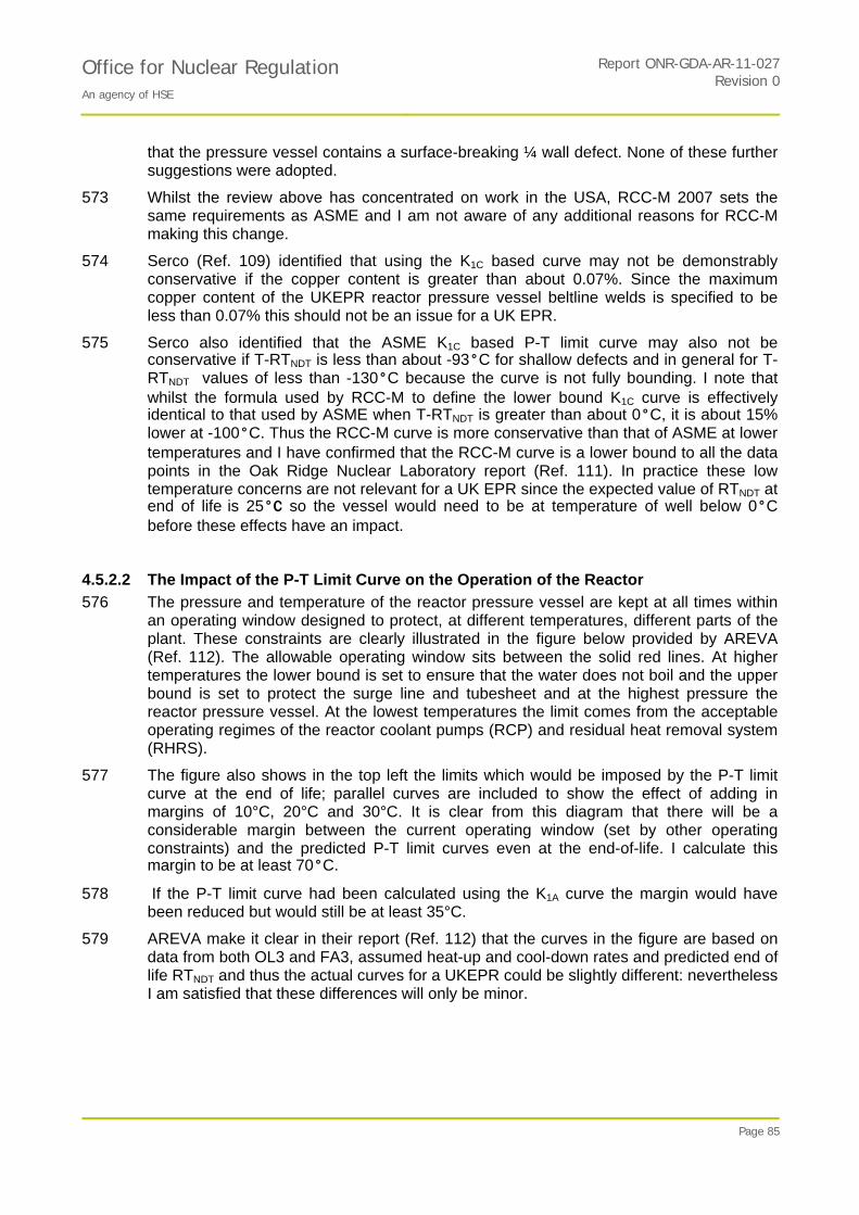
Office for Nuclear Regulation An agency of HSE
Report ONR-GDA-AR-11-027Revision 0
Page 85
that the pressure vessel contains a surface-breaking ¼ wall defect. None of these further suggestions were adopted.
573 Whilst the review above has concentrated on work in the USA, RCC-M 2007 sets the same requirements as ASME and I am not aware of any additional reasons for RCC-M making this change.
574 Serco (Ref. 109) identified that using the K1C based curve may not be demonstrably conservative if the copper content is greater than about 0.07%. Since the maximum copper content of the UKEPR reactor pressure vessel beltline welds is specified to be less than 0.07% this should not be an issue for a UK EPR.
575 Serco also identified that the ASME K1C based P-T limit curve may also not be conservative if T-RTNDT is less than about -93°C for shallow defects and in general for T-RTNDT values of less than -130°C because the curve is not fully bounding. I note that whilst the formula used by RCC-M to define the lower bound K1C curve is effectively identical to that used by ASME when T-RTNDT is greater than about 0°C, it is about 15% lower at -100°C. Thus the RCC-M curve is more conservative than that of ASME at lower temperatures and I have confirmed that the RCC-M curve is a lower bound to all the data points in the Oak Ridge Nuclear Laboratory report (Ref. 111). In practice these low temperature concerns are not relevant for a UK EPR since the expected value of RTNDT at end of life is 25°C so the vessel would need to be at temperature of well below 0°C before these effects have an impact.
4.5.2.2 The Impact of the P-T Limit Curve on the Operation of the Reactor
576 The pressure and temperature of the reactor pressure vessel are kept at all times within an operating window designed to protect, at different temperatures, different parts of the plant. These constraints are clearly illustrated in the figure below provided by AREVA (Ref. 112). The allowable operating window sits between the solid red lines. At higher temperatures the lower bound is set to ensure that the water does not boil and the upper bound is set to protect the surge line and tubesheet and at the highest pressure the reactor pressure vessel. At the lowest temperatures the limit comes from the acceptable operating regimes of the reactor coolant pumps (RCP) and residual heat removal system (RHRS).
577 The figure also shows in the top left the limits which would be imposed by the P-T limit curve at the end of life; parallel curves are included to show the effect of adding in margins of 10°C, 20°C and 30°C. It is clear from this diagram that there will be a considerable margin between the current operating window (set by other operating constraints) and the predicted P-T limit curves even at the end-of-life. I calculate this margin to be at least 70°C.
578 If the P-T limit curve had been calculated using the K1A curve the margin would have been reduced but would still be at least 35°C.
579 AREVA make it clear in their report (Ref. 112) that the curves in the figure are based on data from both OL3 and FA3, assumed heat-up and cool-down rates and predicted end of life RTNDT and thus the actual curves for a UKEPR could be slightly different: nevertheless I am satisfied that these differences will only be minor.
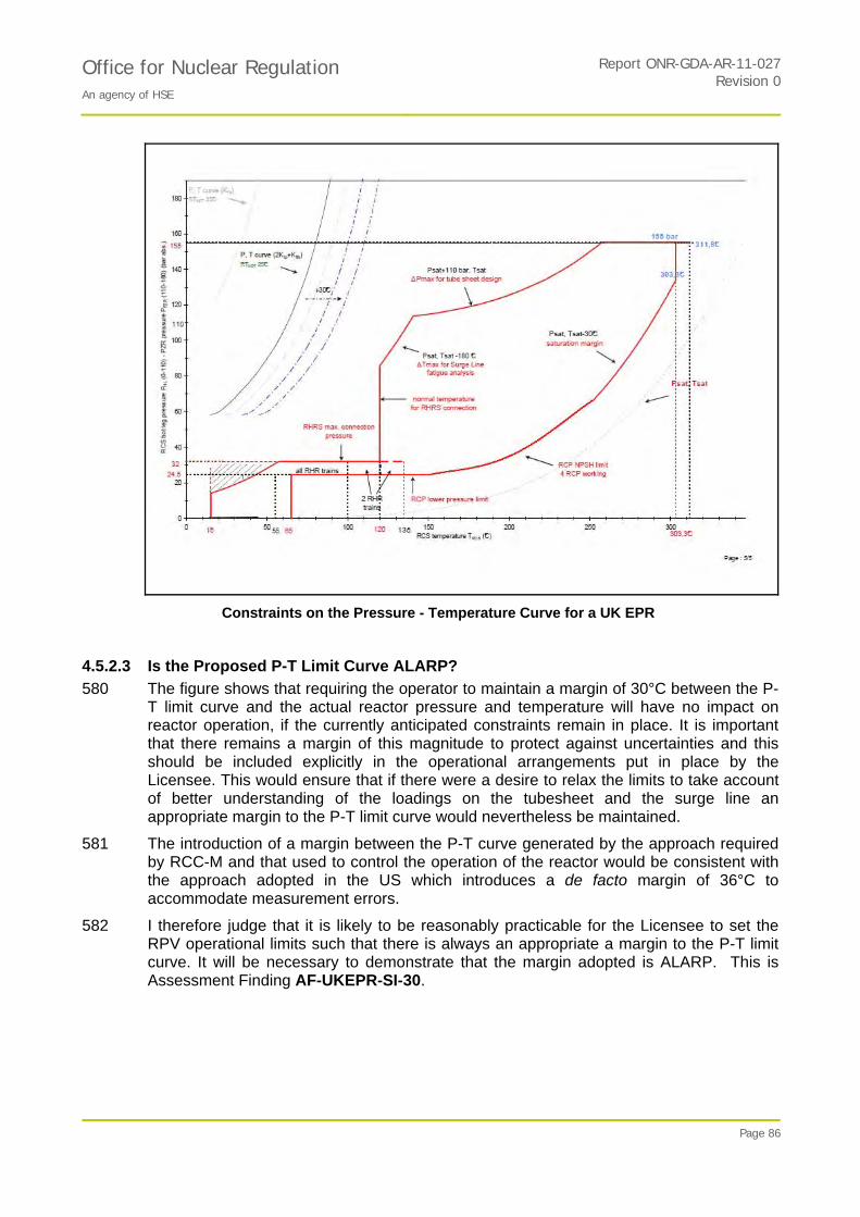
Office for Nuclear Regulation An agency of HSE
Report ONR-GDA-AR-11-027Revision 0
Page 86
Constraints on the Pressure - Temperature Curve for a UK EPR
4.5.2.3 Is the Proposed P-T Limit Curve ALARP?
580 The figure shows that requiring the operator to maintain a margin of 30°C between the P-T limit curve and the actual reactor pressure and temperature will have no impact on reactor operation, if the currently anticipated constraints remain in place. It is important that there remains a margin of this magnitude to protect against uncertainties and this should be included explicitly in the operational arrangements put in place by the Licensee. This would ensure that if there were a desire to relax the limits to take account of better understanding of the loadings on the tubesheet and the surge line an appropriate margin to the P-T limit curve would nevertheless be maintained.
581 The introduction of a margin between the P-T curve generated by the approach required by RCC-M and that used to control the operation of the reactor would be consistent with the approach adopted in the US which introduces a de facto margin of 36°C to accommodate measurement errors.
582 I therefore judge that it is likely to be reasonably practicable for the Licensee to set the RPV operational limits such that there is always an appropriate a margin to the P-T limit curve. It will be necessary to demonstrate that the margin adopted is ALARP. This is Assessment Finding AF-UKEPR-SI-30.
Office for Nuclear Regulation An agency of HSE
Report ONR-GDA-AR-11-027Revision 0
Page 87
4.5.3 Conclusions and Findings relating to Reactor Pressure Vessel Pressure -Temperature Limit Diagrams and Low Temperature Overpressure Protection
583 There will be a considerable margin between the current operating window (set by other operating constraints) and the predicted P-T limit curves even at the end-of-life. However, there are sufficient margins on other constraints that ALARP improvements may be possible.
584 I have raised one Assessment Finding in this area:
AF-UKEPR-SI-30: The Licensee shall define the Operational Limits to ensure the operating pressure and temperature for the reactor pressure vessel are always separated from the P-T limit curve by a significant margin at all temperatures.
585 This should be completed before the generic milestone of Hot Operations because this margin must be maintained at all times once the reactor pressure vessel is taken to operational temperatures.
4.6 RCC-M Issues
4.6.1 RCC-M Aspects of Requirements for Design Analysis of Piping Class 1, 2 and 3
4.6.1.1 Background
586 The Step 3 Assessment Report (Ref. 8) in Section 5.15 raised two matters relating to piping design in the RCC-M code. These matters were identified in a review of the RCC-M code (Ref. 113). The matters were raised with EDF and AREVA through Regulatory Observation RO-UKEPR-36 and listed in the Step 4 Assessment Plan (Ref. 6) as Item AR09060-7.
587 The activity has two aspects:
1. The design analysis equations in RCC-M for primary loads for Class 2 and Class 3 pipework differ from those currently adopted in ASME III.
2. The treatment of earthquake and other reversing dynamic loads for which the methodology set out in RCC-M appears to be unique.
588 For the first aspect above, for Class 2/3 pipework, the equations in RCC-M are the same as equations that appeared in the ASME III code between 1971 and 1981.
589 EDF and AREVA were asked for an explanation of why the design analysis equations in RCC-M are unchanged compared with ASME (aspect 1 above) and for the basis of the approach to earthquake loading analysis of pipework (aspect 2 above).
590 There was some discussion between ND and EDF and AREVA on the matters relating to piping design. However within GDA Step 3, ND assessment did not reach a conclusion.
591 During GDA Step 4, I have further reviewed the matters relating to RCC-M piping design with the aid of a specialist contractor familiar with piping design analysis (Ref. 114).
592 The following two sub-sections deal with the RCC-M piping design analysis equations and treatment of earthquake loads.
4.6.1.2 RCC-M Piping Design Analysis Equations for Primary Loads
593 For Class 2/3 pipework, the equations in RCC-M are the same as equations that appeared in the ASME III code between 1971 and 1981. The current ASME III code (2010 edition) contains the equations introduced in 1981. The difference is greatest for Class 2 and 3 piping, with more minor differences for Class 1 piping.

Office for Nuclear Regulation An agency of HSE
Report ONR-GDA-AR-11-027Revision 0
Page 88
594 For the Class 2/3 design analysis equations for piping, the RCC-M equations are the same as originally appeared in the US B31.1 design code in 1955. B31.1 still has the same equations. The same form of design analysis equations appears in the corresponding European standard EN 13480-3.
595 During GDA Step 3, EDF and AREVA responded to the Actions RO-UKEPR-36.A1 and A2 and provided three documents (Refs 115,116,117).
596 The ND understanding of the response from EDF and AREVA is that:
a) Experience with piping designed to the B31.1/ EN13480 equations; and
b) Comparison of B31.1/EN13480 equations with experimental data showing adequate margins outweigh any theoretical concerns about the basis of the i-factor that multiplies the moment term in the design analysis equations, taking account of the different stress limits between the RCC-M and ASME III code equations. In addition, comparisons of design code predictions and margins to experimental test results indicate acceptable margins.
597 A further report was supplied in December 2009 (Ref. 118) in response to a request to comment directly on two reports prepared on behalf of ASME. Because of the specialist nature of this topic I decided to ask a contractor experienced with design of pipework to undertake a review of the issues.
598 Rather than deal with the RCC-M design equation matter from a theoretical basis, I asked my contractor to concentrate on answering the question:
Does using the RCC-M equation for piping design make any difference to the actual piping, compared with using the ASME III corresponding piping equations?
599 Example assessments were carried out for a ferritic steel and an austenitic stainless steel, assessing the stresses in a straight pipe, a welding elbow and a welding tee using RCC-M Class 2 and ASME III Class 2 under design limits. Combinations of pressure and moment loadings were selected to indicate the conditions under which RCC-M Class 2 is more or less conservative than ASME III Class 2. The materials and components have been chosen to be representative of those which may typically be used in Class 2 PWR pipework.
600 The design rules have been applied on the basis that the pipe thickness is selected with a small margin against hoop pressure loading (i.e. an economic design). The results are expressed as reserve factors which are evaluated, for each Code and situation, as the allowable stress divided by the combined stress. Consequently, the lower the reserve factor the more conservative is the Code.
601 In terms of the actual wall thickness required for a given pressure for a pipe of given internal diameter and material, (i.e. pressure induced hoop stress basis for wall thickness) it is important to note that the requirements of RCC-M and ASME III are the same. This means that at the outset of the design process, the minimum wall thickness will be the same for both design codes, all other things being equal. The further design analysis equations for longitudinal (i.e. axial) stresses in the pipe wall would only be important if they required a greater wall thickness, or required a large difference in flexibility of support arrangements. Of course pressure-induced hoop stress is twice the pressure-induced longitudinal stress.
602 For the ferritic material when pressure loading is dominant RCC-M always provides the limiting (ie lowest) reserve factor. For all the straight pipe situations analysed, RCCM Class 2 is more conservative than ASME 2, but for certain of the conditions analysed there is a cross-over for elbows and tees in situations where the bending moment is very

Office for Nuclear Regulation An agency of HSE
Report ONR-GDA-AR-11-027Revision 0
Page 89
large. In other words, RCC-M is more conservative than ASME III for ferritic pipework except for certain unusual situations where the bending moment is very large compared with the pressure loading.
603 For the austenitic material RCC-M provides the limiting reserve factor for all components and cases considered except for the welding tee under the case with highest moment. For the latter situation, ASME is marginally more limiting, although it should be noted that both RCC-M and ASME reserve factors are less than unity for this case.
604 Hence, based on these simple examples, a pipework system designed to RCC-M would almost certainly meet the ASME code limits except in cases where moment loading is very large compared to pressure loading.
605 Ref. 114 notes that "When assessing fault loadings, it is apparent that, compared to design limits, the ASME Class 2 limits on piping systems subject to Level B, Level C and Level D loadings are more restrictive than the RCC-M Class 2 limits and particularly so for typical austenitic materials."
606 The allowable stress limits for Levels B, C and D loadings are compared with the basic design limits in the table below (from Ref. 114). Sh is the material allowable basic stress and Sy is the yield strength, both at the design temperature. For both Codes the material allowable basic stress Sh is defined either as a function of tensile strength or 0.9Sy whichever is the lower. However, ASME differs from RCC-M in that service limits B, C and D are based on the more restrictive of two values, one based on Sh and the other based on Sy.
Allowable Stress Limits for Service Conditions
Loading condition RCC-M Class 2 ASME Class 2
Design Sh 1.5 Sh
Level B 1.2 Sh 1.8 Sh or 1.5 Sy
Level C 1.8 Sh 2.25 Sh or 1.8 Sy
Level D 2.4 Sh 3 Sh or 2 Sy
607 For ferritic materials the additional yield-based limits in ASME are not governing. However for austenitic materials the allowable stress is governed by the relaxed 0.9 Sy and the Sy term becomes governing. The allowable limits for level B, C and D conditions are expressed as a ratio of the design limit in the table below (from Ref. 114). The design limits, as in the table above, are Sh for RCC-M and 1.5Sh (where Sh = 0.9 Sy) for ASME.
Ratio of Allowable Limits to Design Limits for Level B, C and D Service Conditions
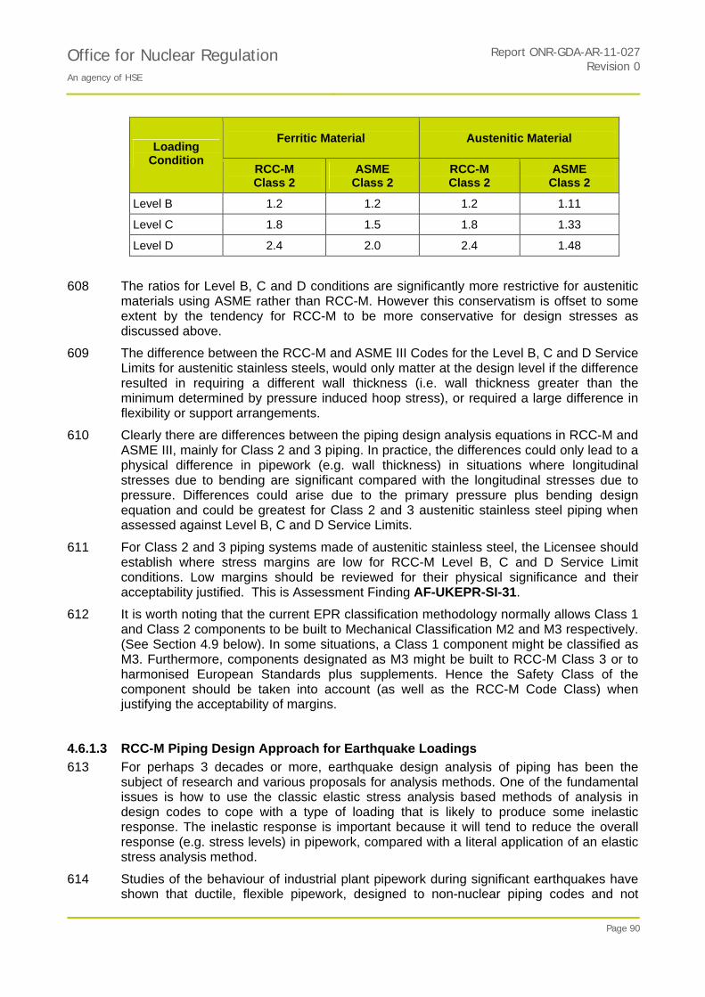
Office for Nuclear Regulation An agency of HSE
Report ONR-GDA-AR-11-027Revision 0
Page 90
Ferritic Material Austenitic Material Loading
Condition RCC-M Class 2
ASME Class 2
RCC-M Class 2
ASME Class 2
Level B 1.2 1.2 1.2 1.11
Level C 1.8 1.5 1.8 1.33
Level D 2.4 2.0 2.4 1.48
608 The ratios for Level B, C and D conditions are significantly more restrictive for austenitic materials using ASME rather than RCC-M. However this conservatism is offset to some extent by the tendency for RCC-M to be more conservative for design stresses as discussed above.
609 The difference between the RCC-M and ASME III Codes for the Level B, C and D Service Limits for austenitic stainless steels, would only matter at the design level if the difference resulted in requiring a different wall thickness (i.e. wall thickness greater than the minimum determined by pressure induced hoop stress), or required a large difference in flexibility or support arrangements.
610 Clearly there are differences between the piping design analysis equations in RCC-M and ASME III, mainly for Class 2 and 3 piping. In practice, the differences could only lead to a physical difference in pipework (e.g. wall thickness) in situations where longitudinal stresses due to bending are significant compared with the longitudinal stresses due to pressure. Differences could arise due to the primary pressure plus bending design equation and could be greatest for Class 2 and 3 austenitic stainless steel piping when assessed against Level B, C and D Service Limits.
611 For Class 2 and 3 piping systems made of austenitic stainless steel, the Licensee should establish where stress margins are low for RCC-M Level B, C and D Service Limit conditions. Low margins should be reviewed for their physical significance and their acceptability justified. This is Assessment Finding AF-UKEPR-SI-31.
612 It is worth noting that the current EPR classification methodology normally allows Class 1 and Class 2 components to be built to Mechanical Classification M2 and M3 respectively. (See Section 4.9 below). In some situations, a Class 1 component might be classified as M3. Furthermore, components designated as M3 might be built to RCC-M Class 3 or to harmonised European Standards plus supplements. Hence the Safety Class of the component should be taken into account (as well as the RCC-M Code Class) when justifying the acceptability of margins.
4.6.1.3 RCC-M Piping Design Approach for Earthquake Loadings
613 For perhaps 3 decades or more, earthquake design analysis of piping has been the subject of research and various proposals for analysis methods. One of the fundamental issues is how to use the classic elastic stress analysis based methods of analysis in design codes to cope with a type of loading that is likely to produce some inelastic response. The inelastic response is important because it will tend to reduce the overall response (e.g. stress levels) in pipework, compared with a literal application of an elastic stress analysis method.
614 Studies of the behaviour of industrial plant pipework during significant earthquakes have shown that ductile, flexible pipework, designed to non-nuclear piping codes and not

Office for Nuclear Regulation An agency of HSE
Report ONR-GDA-AR-11-027Revision 0
Page 91
explicitly designed for earthquake loads, is nevertheless very resilient to earthquake loadings.
615 Nuclear piping design codes have struggled to find procedures based on elastic stress analysis that are consistent with the observed practical behaviour of ductile, flexible pipework. In other words, there has been a claim that design analysis methods for pipework have resulted ‘an over design', in particular with too many supports and reduced flexibility compared with what is desirable for normal plant operation.
616 The ASME III Code of 1994 introduced a new method for dealing with earthquake loading (in general, any reversing dynamic loading) in the design of pipework. The new ASME III method was revised in 2004, with a reduction in the stress limit but also a reduction in the B factor applied to the bending moment term. However, the method in ASME III 1994 edition, and beyond has not been accepted by US NRC.
617 The RCC-M code has also addressed the issue of earthquake loading analysis of pipework. The procedure in the RCC-M code was introduced with the 2002 Addendum to the code and is different from that in ASME III. The method used in RCC-M also seeks to reconcile analysis methods that are based on linear elastic methods with actual piping response. This response is expected to be, to some degree, non-linear, mainly due to plastic deformation; at least for seismic loadings that are significant for response of piping. The approach is a combination of engineering insight and validation by comparison with a number of tests. Overall, the approach is pragmatic and relies on a demonstration of suitable margins as shown by experiments.
618 It should be noted that in the RCC-M method for earthquake design analysis of piping, the stress limits are not changed; the only change is to the effective bending moment for the dynamic part of the earthquake induced bending moment.
619 Some background to and justification of the method adopted in the RCC-M code is given in Ref. 115. This refers to a body of earlier papers (period 1995 to 1999) which contribute to the basis for the method adopted in the RCC-M code. Although Ref. 115 provides some justification for the procedure adopted, it does not explain how the procedure now in the RCC-M Code evolved.
620 Ref. 115 mentions two reference tests that validate the method adopted in RCC-M. Overall, Ref. 115 claims that even for a level D Service Limit condition, the earthquake analysis procedure in RCC-M still gives a margin of 2 between the stress limit and failure. Generally, the RCC-M procedure is more conservative than the ASME III method (1994 or 2004), though at 2% damping the ASME III method appears to give a slightly larger margin (Table 2 of Ref. 115).
621 EASL’s report (Ref. 114) expresses a number of reservations about the RCC-M method for dealing with earthquake design analysis of piping. However as an overall summary it states:
"Although different from the current ASME approach, it is considered that the RCC-M approach is a sensible option theoretically."
622 The overall conclusion here is the RCC-M earthquake design analysis procedure for piping is a reasonable, mainly empirical way of at least partly resolving the gap between a purely linear elastic stress analysis of a piping system and the practical behaviour of ductile, flexible piping when subjected to earthquakes of considerable magnitude.
623 For the RCC-M procedure for earthquake design analysis of piping, there is a lack of guidance in several areas, for example:

Office for Nuclear Regulation An agency of HSE
Report ONR-GDA-AR-11-027Revision 0
Page 92
Methods of dynamic analysis that are consistent with the procedure, damping values to be used and factors that affect the choice of damping (e.g. load level).
Recommendations for support of concentrated masses.
The need for a ‘balanced' design, that is avoidance of plastic strain concentrations at isolated locations.
The need to ensure that piping system main frequencies of response are in the 'low frequency' range.
The methods for assessing piping tees.
624 Assessment Finding AF-UKEPR-SI-32 addresses this matter.
4.6.1.4 Conclusions and Findings Relating to RCC-M Design Analysis of Piping
625 RCC-M is more conservative than ASME III for ferritic pipework design except for certain unusual situations where the bending moment is very large compared with the pressure loading.
626 For austenitic material, under design load conditions, RCC-M provides the limiting reserve factor for all components and cases considered except for the welding tee under the case with highest moment where ASME is marginally more limiting.
627 Hence, based on these simple examples, a pipework system designed to RCC-M would almost certainly meet the ASME code limits except in cases where moment loading is very large compared to pressure loading.
628 Under other load conditions, especially for Class 2 and Class 3 austenitic pipework, RCC-M may be significantly less conservative than ASME III.
AF-UKEPR-SI-31: For Class 2 and 3 piping systems made of austenitic stainless steel, the Licensee shall establish where stress margins are low for RCC-M Level B, C and D Service Limit conditions. Any low margins should be reviewed for their physical significance and whether they are acceptable.
629 The RCC-M earthquake design analysis procedure for piping is a reasonable, mainly empirical way of at least partly resolving the gap between a purely linear elastic stress analysis of a piping system and the practical behaviour of ductile, flexible piping when subjected to earthquakes of considerable magnitude.
AF-UKEPR-SI-32: The Licensee shall ensure that more detailed guidance on the use of the RCC-M procedure is provided to support earthquake design of pipework.
630 The two findings on this topic shall both be completed before the generic milestone of RPV installation although in practice it might need to be completed earlier to suit the programme for procurement of piping systems. This is because it would be extremely difficult to make any substantive changes once the components start to be installed which could then lead to substantial delays and additional costs.
4.6.2 Comparison of RCC-M and ASME Welding III Procedures
4.6.2.1 Background and Key Issues from Step 3 Assessment
631 This activity is AR09060-9.1 on the Action Plan and was not the subject of a Regulatory Observation.
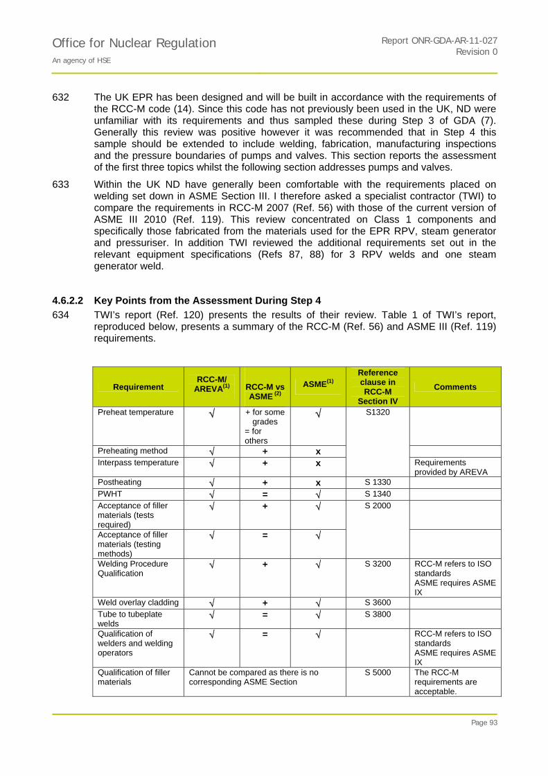
Office for Nuclear Regulation An agency of HSE
Report ONR-GDA-AR-11-027Revision 0
Page 93
632 The UK EPR has been designed and will be built in accordance with the requirements of the RCC-M code (14). Since this code has not previously been used in the UK, ND were unfamiliar with its requirements and thus sampled these during Step 3 of GDA (7). Generally this review was positive however it was recommended that in Step 4 this sample should be extended to include welding, fabrication, manufacturing inspections and the pressure boundaries of pumps and valves. This section reports the assessment of the first three topics whilst the following section addresses pumps and valves.
633 Within the UK ND have generally been comfortable with the requirements placed on welding set down in ASME Section III. I therefore asked a specialist contractor (TWI) to compare the requirements in RCC-M 2007 (Ref. 56) with those of the current version of ASME III 2010 (Ref. 119). This review concentrated on Class 1 components and specifically those fabricated from the materials used for the EPR RPV, steam generator and pressuriser. In addition TWI reviewed the additional requirements set out in the relevant equipment specifications (Refs 87, 88) for 3 RPV welds and one steam generator weld.
4.6.2.2 Key Points from the Assessment During Step 4
634 TWI’s report (Ref. 120) presents the results of their review. Table 1 of TWI’s report, reproduced below, presents a summary of the RCC-M (Ref. 56) and ASME III (Ref. 119) requirements.
Requirement RCC-M/
AREVA(1)
RCC-M vs ASME (2)
ASME(1) Reference clause in RCC-M
Section IV
Comments
Preheat temperature + for some grades
= for others
Preheating method + x
Interpass temperature + x
S1320
Requirements provided by AREVA
Postheating + x S 1330
PWHT = S 1340
Acceptance of filler materials (tests required)
+
Acceptance of filler materials (testing methods)
=
S 2000
Welding Procedure Qualification
+ S 3200 RCC-M refers to ISO standards ASME requires ASME IX
Weld overlay cladding + S 3600
Tube to tubeplate welds
= S 3800
Qualification of welders and welding operators
= RCC-M refers to ISO standards ASME requires ASME IX
Qualification of filler materials
Cannot be compared as there is no corresponding ASME Section
S 5000 The RCC-M requirements are acceptable.
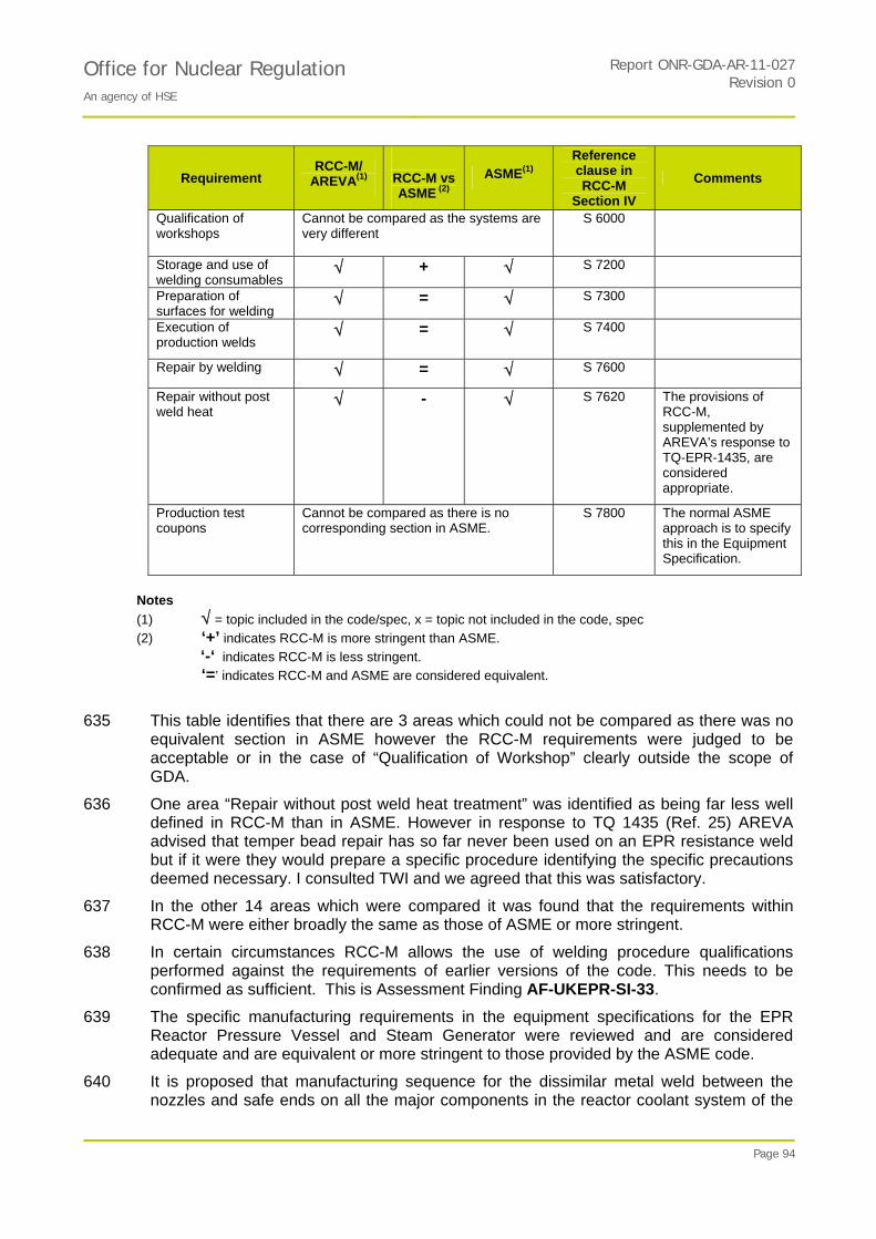
Office for Nuclear Regulation An agency of HSE
Report ONR-GDA-AR-11-027Revision 0
Page 94
Requirement RCC-M/
AREVA(1)
RCC-M vs ASME (2)
ASME(1) Reference clause in RCC-M
Section IV
Comments
Qualification of workshops
Cannot be compared as the systems are very different
S 6000
Storage and use of welding consumables
+ S 7200
Preparation of surfaces for welding
= S 7300
Execution of production welds
= S 7400
Repair by welding = S 7600
Repair without post weld heat
- S 7620 The provisions of RCC-M, supplemented by AREVA’s response to TQ-EPR-1435, are considered appropriate.
Production test coupons
Cannot be compared as there is no corresponding section in ASME.
S 7800 The normal ASME approach is to specify this in the Equipment Specification.
Notes
(1) = topic included in the code/spec, x = topic not included in the code, spec
(2) ‘+’ indicates RCC-M is more stringent than ASME.
‘-‘ indicates RCC-M is less stringent.
‘=’ indicates RCC-M and ASME are considered equivalent.
635 This table identifies that there are 3 areas which could not be compared as there was no equivalent section in ASME however the RCC-M requirements were judged to be acceptable or in the case of “Qualification of Workshop” clearly outside the scope of GDA.
636 One area “Repair without post weld heat treatment” was identified as being far less well defined in RCC-M than in ASME. However in response to TQ 1435 (Ref. 25) AREVA advised that temper bead repair has so far never been used on an EPR resistance weld but if it were they would prepare a specific procedure identifying the specific precautions deemed necessary. I consulted TWI and we agreed that this was satisfactory.
637 In the other 14 areas which were compared it was found that the requirements within RCC-M were either broadly the same as those of ASME or more stringent.
638 In certain circumstances RCC-M allows the use of welding procedure qualifications performed against the requirements of earlier versions of the code. This needs to be confirmed as sufficient. This is Assessment Finding AF-UKEPR-SI-33.
639 The specific manufacturing requirements in the equipment specifications for the EPR Reactor Pressure Vessel and Steam Generator were reviewed and are considered adequate and are equivalent or more stringent to those provided by the ASME code.
640 It is proposed that manufacturing sequence for the dissimilar metal weld between the nozzles and safe ends on all the major components in the reactor coolant system of the
Office for Nuclear Regulation An agency of HSE
Report ONR-GDA-AR-11-027Revision 0
Page 95
EPR will not include buttering of the surface. This is not normal practice within the UK but has been previously applied on nuclear pressure vessels by both AREVA and Westinghouse.
641 TWI judge this technique to be acceptable and do not foresee any major technical difficulties. The greatest potential concern is from sensitisation and embrittlement of the stainless steel and it is therefore recommended that the Licensee satisfies himself that this is not a concern. I anticipate that this could be achieved through examination of the welding procedure qualification test pieces or review of the experience with welds made using the same procedure. This is Assessment Finding AF-UKEPR-SI-34.
642 It is concluded that the RCC-M requirements for welding are generally at least as stringent as those required by ASME and RCC-M is therefore an acceptable Code for controlling the welding of a UK EPR.
4.6.2.3 Welding NDT
643 In Section 4.2.4 above I reviewed the requirements for the qualified inspections of the HICs at the end of manufacture. However other in-process inspections of the HICs as well as all the inspections of the majority of the structural components will be carried out in accordance with the RCC-M code. Consequently, with the assistance of a technical support contract (Ref. 120) I have compared these requirements with those required by ASME III.
644 In general terms the RCC-M requirements for examinations of the full penetration welds are similar to ASME III and are thorough. For example both require that all Class 1 welds are inspected with both a volumetric and a surface technique.
645 For the surface inspection techniques the requirements of the two codes are broadly equivalent although the lighting requirements for coloured inks are only 500 lux for RCC-M compared to 1000 lux for ASME. Since the RCC-M requirement is the same as the British Standard BS EN ISO 3059 (2001) (Ref. 121) I am satisfied that this is adequate.
646 For radiography RCC-M requirements are more stringent than ASME. For instance both require the use of image quality indicators to confirm sensitivity but RCC-M requires smaller holes or narrower wires to be detected. Geometric unsharpness is specified for each code in different way but the general effect is for the RCC-M requirements to be more stringent.
647 For ultrasonics there are differences between the two codes in how the examination requirements are built up. The cumulative effect of the different measures on the ability to achieve an absolute level of capability for both of the codes is difficult to quantify but in general RCC-M requirements appear to be better defined and procedures will be more sensitive to small defects.
648 Like ASME III, RCC-M allows small volumetric defects to remain in the weld; large ones have to be repaired; no planar defects are permitted. So it is important that the inspection is able to correctly discriminate between volumetric and planar defects. This should be relatively straightforward with radiography provided any planar defect is well aligned with the beam and the defect does not have a mixture of planar and volumetric characteristics (hybrid defect). However for defects only detected with ultrasonics such characterisation can be more complex.
649 For ultrasonics, RCC-M Section III Clause MC2637 specifies that the volumetric/non-volumetric character of defects should be determined by the cascade procedure given in
Office for Nuclear Regulation An agency of HSE
Report ONR-GDA-AR-11-027Revision 0
Page 96
Document B of the French Institute of Welding IS US 319-21. However as an alternative it allows the use of the European Standard EN 1713.
650 In recent years ultrasonic operator training in the UK has been based on EN1713. Defects are classified in this standard using the following parameters.
Welding technique.
Geometrical position of the indication.
Maximum echo height.
Directional reflectivity.
Echostatic pattern.
Echodynamic pattern.
651 A flowchart is provided to guide the operator through the classification using these parameters.
652 Generally TWI supported the use of EN1713 although they identified that, in their view, it would be more appropriate to treat echostatic and echodynamic patterns together rather than separately. They also noted that when signals are detected which appear to come from a small volumetric defect it is important to check for small subsidiary signals since these could indicate that the defect is actually rough and planar. These comments should be considered when the inspection procedures are prepared.
653 There was not time to review the French Standard IS US 319-21 or the alternative European Standard EN 1713 during the GDA and so I am unable to form a view on how effective these procedures will be for correctly characterising planar or hybrid defects. However given the importance of accurate characterisation it is important that this part of the procedure is carefully reviewed to ensure that best practice is being followed. This aspect has already been identified in Section 4.2.4.5.5 in connection with the prototype ultrasonic application, and will be taken forward as part of GI-UKEPR-SI-01 Action 6 for the qualified manufacturing inspections. For the other (non-qualified) inspections the need for evidence that the inspection procedures are effective in identifying and rejecting planar defects may be regarded as part of Assessment Finding AF-UKEPR-SI-07.
4.6.2.4 Conclusions and Findings Relating to RCC-M Welding Procedures
654 The RCC-M requirements for welding are generally at least as stringent as those required by ASME and RCC-M is therefore an acceptable Code for controlling the welding of a UK EPR.
655 I am satisfied that it is appropriate to use the RCC-M code to control the inspections of all the safety-related components which are not HICs provided the Licensee demonstrates that the complete inspection is capable of effectively identifying and rejecting defects of concern, especially planar defects.
656 There are two findings which shall both be completed before the generic milestone of RPV installation although in practice they will need to be completed earlier to meet the manufacturing programme. This is because it would be extremely difficult to make any substantive changes once the components start to be installed which could then lead to substantial delays and additional costs.
AF-UKEPR-SI-33: The Licensee shall ensure that if a welding procedure qualification is performed against the requirements of earlier versions of the code a

Office for Nuclear Regulation An agency of HSE
Report ONR-GDA-AR-11-027Revision 0
Page 97
competent welding engineer reviews whether this is adequate and documents the review.
AF-UKEPR-SI-34: The Licensee shall confirm that the dissimilar metal weld procedure does not result in an unacceptable degree of sensitisation and embrittlement of the safe end material during the final PWHT.
4.6.3 Review of RCC-M Design Requirements for Pressure Boundaries of Pumps and Valves
4.6.3.1 Background and Key Issues from Step 3 Assessment
657 This activity is AR09060-10 on the Action Plan and was not the subject of a Regulatory Observation.
658 The EPR has been designed, and will be built, in accordance with the requirements of the RCC-M code (Ref. 56). Since this code has not previously been used in the UK ND were unfamiliar with its requirements and thus sampled its requirements during Step 3 of GDA (Ref. 8). Generally this review was positive however it was recommended that in Step 4 that this sample should be extended to include welding, fabrication, manufacturing inspections and the pressure boundaries of pumps and valves. This section reports the assessment of the last item.
659 Within the UK we have generally been comfortable with the requirements placed on the design of the pressure boundary for pumps and valves set down in ASME Section III. I therefore asked Serco to compare the requirements in RCC-M 2007 with those of the current version of ASME III (Ref. 119). This work was carried out in two phases, first a systematic review to identify the differences and secondly an assessment of the significance of these. For completeness, changes added to RCC-M in the 2008 and 2009 addenda were also reviewed.
4.6.3.2 Key Points from the Assessment During Step 4
660 Serco’s report (Ref. 122) presents the results of their review, the differences are tabulated in the appendices and the conclusions are summarised below.
4.6.3.3 Conclusions and Findings Relating to Use of RCC-M for Defining the Pressure Boundaries of Pumps and Valves
661 For Class 1 pumps there is a clear difference in approach between the two codes. RCC-M refers back to general pressure vessel design by analysis rules whereas ASME identifies six pump types each with their own detailed rules. Although the RCC-M approach may be a more bespoke and therefore a less conservative design, given that it complies with the RCC-M rules for pressure vessels it is acceptable.
662 At the Class 2 and 3 level both codes identify a number of pump types and specific rules for each. There were many detailed differences in the rules for the different types of pump but apart from two exceptions given below these were judged not to be significant.
663 For a number of pump types RCC-M requires a fillet radius on the casing to be the greater of 6mm or 20% of the thickness whereas ASME requires the greater of 6 mm or 10% of the thickness. So an ASME designed pump could have a smaller filler radius and would thus be more susceptible to fatigue cracking. The RCC-M Code is thus more conservative than ASME in this respect.
Office for Nuclear Regulation An agency of HSE
Report ONR-GDA-AR-11-027Revision 0
Page 98
664 The second significant difference is for Class 2, Type A pumps where ASME required that the thickness was greater than two parameters whereas RCC-M required that it was the greater of three parameters. From a cursory look at these it appeared that RCC-M could allow pumps casings only half as thick as those allowed by ASME. However AREVA explained in their response to TQ 1389 (8) that the third parameter would ensure that this would not occur and furthermore there are no pumps of this type in the EPR.
665 I conclude that the RCC-M Code is an adequate basis for designing pump pressure boundaries.
666 For valves, both codes use a similar approach but have numerous differences in detail. It was not possible to test all possible combinations of design parameters but no significant differences were identified. It is therefore concluded that the use of the RCC-M code for specifying valve pressure boundaries is acceptable.
4.6.3.4 Conclusions and Findings Relating to Design of Pressure Boundaries of Pumps and Valves
667 The RCC-M Code is an adequate basis for designing the pressure boundaries of pumps and valves.
668 There are no Assessment Findings on this topic.
4.7 Environmental Effects on Fatigue Design Curves
669 In the last few years questions have arisen about whether code fatigue design analysis methods and code fatigue design curves (S-N curves) adequately account for the effects of Light Water Reactor (LWR) water environments. Although a good deal of experimental and analytical work has been done in this area, there are still uncertainties and something of a lack of consensus across the international nuclear industry. I therefore commissioned a review of the current position, Ref. 123, from a retired ND inspector, under a ‘fees for service’ contract.
670 The effects are most relevant to stainless steel components as they are in direct contact with the LWR environment, but it is also relevant to un-clad PWR ferritic steel components, for example the Steam Generator secondary shells. There do not appear to be any issues to address for Nickel-Chrome-Iron alloys.
4.7.1 Current Position and the Way Forward
671 Efforts have been made worldwide from at least the late 1990s to determine the effects of LWR water environments on the fatigue life of metal components, and important work conducted at Argonne National Laboratory (ANL), sponsored by the (US NRC) culminated in 2007 with issue of NUREG/CR-6909, Effect of LWR Coolant Environments on the Fatigue Life of Reactor Materials, Ref. 124.
672 The fatigue evaluation procedure proposed in NUREG/CR-6909 has been adopted into USNRC Regulatory Guide 1.207 (Ref. 125) without change, and the USNRC considers this to be applicable to new nuclear reactor designs. The ASME III Code has been revised (2009 Addenda) to include a fatigue design curve for stainless steel in air which is the same as that recommended in NUREG/CR-6909, but importantly the environmental enhancement factors, Fen, are the subject of code cases which are still under discussion and have not yet been included.

Office for Nuclear Regulation An agency of HSE
Report ONR-GDA-AR-11-027Revision 0
Page 99
673 I raised the question of EDF and AREVA’s position on the effect of this work on the EPR fatigue analysis in TQ-EPR-643, Ref. 25. The response agrees that there is a need for a new in-air fatigue design curve for stainless steel, but contends that the Fen factors proposed in NUREG/CR-6909 and Regulatory Guide 1.207 result in fatigue usage estimates that are too conservative compared with plant conditions. They conclude that there are no technical reasons to change significantly and urgently the RCC-M practice (Ref. 56) and as a consequence make no proposals of how this should be addressed for the EPR.
674 The response cites several papers published by French researchers in the past two or three years, but makes no mention of the fatigue design review procedures that have been publicly proposed by EDF and AREVA, for example Ref. 126, nor the potential to apply these to plants currently under construction.
675 Within the context of NII's GDA the question arises as to how to deal with this situation consistently across all new designs that might be assessed.
676 For a plant still to be built in the UK it is reasonable to expect that fatigue design analyses are reviewed to determine the potential effects of environmental effects on predicted fatigue life. The review procedure adopted by the Licensee should take account of recent results of research and development in this area. Although the review would be most relevant to stainless steel components, a similar approach should also be adopted for any ferritic components that require a code fatigue design analysis and are in contact with the wetted environment, for example the SG secondary shells.
677 One way forward could be to establish a fatigue design evaluation review procedure that:
1. Takes account of the generally accepted revision to the (in air) fatigue design curve. For example the sort of curve now incorporated in the 2010 Edition of the ASME III Code for austenitic stainless steel - or a similar fatigue design curve that might proposed in other Codes (e.g. RCC-M);
2. Includes a basis for determining environmental enhancement factors for fatigue;
3. Includes some form of 'screening criterion' based on environmental enhancement factors. If a particular location was below the screening criterion then no further action would be needed. However if a location was above the screening criterion then it would require specific, further consideration.
678 There might be other review procedures that could adequately address the issue, but whatever review procedure the Licensee adopts, it is important that the basis of the procedure be clear and justified. Supporting material justifying the basis of the procedure should be available for scrutiny if NII chose to assess the review work.
679 I do not believe that it is necessary to have undertaken this fatigue design evaluation within the timeframe of GDA, but it will need to be completed during the Licensing phase and before commercial operation can start. As a result the Licensee will have to undertake a fatigue design evaluation for locations in austenitic stainless steel and ferritic components that are in contact with the wetted environment to ensure that the effects of environment have been properly accounted for in the fatigue design analysis, and I have taken this forward as Assessment Finding AF-UKEPR-SI-35.
680 I also believe that a thorough review of fatigue design analysis should be undertaken for the first Periodic Safety Review (10 years after start of commercial operation) as there may be an internationally agreed way of dealing with fatigue design analysis with a PWR water environment by that stage. I have decided that it would be unreasonable to set out expectations for the Periodic Safety review as an Assessment Finding, and the comment

Office for Nuclear Regulation An agency of HSE
Report ONR-GDA-AR-11-027Revision 0
Page 100
is for information only. This approach recognises the NRC position that designs submitted before the new Regulatory Guide will not have to meet the guidance until licence extension after 40 years of operation.
4.7.2 Conclusions and Findings on Environmental Effects on Fatigue Design Curves
681 EDF and AREVA have not yet adequately addressed the emerging findings on the affect of environment on fatigue design curves in their fatigue analysis for the EPR.
682 I accept that although the USNRC has clearly stated its position on these effects, there remain uncertainties and something of a lack of consensus across the international nuclear industry as to how this matter should be addressed.
683 I do not believe that it would be practicable for EDF and AREVA to have meaningfully addressed this matter within GDA, but that it is reasonable to expect the matter is addressed prior to commercial operation. I therefore believe that the Licensee will have to undertake a fatigue design evaluation for locations in austenitic stainless steel and ferritic components that are in contact with the wetted environment to ensure that the effects of environment have been properly accounted for in the fatigue design analysis, and I have taken this forward as Assessment Finding AF-UKEPR-SI-35.
AF-UKEPR-SI-35: The Licensee shall undertake a fatigue design evaluation for locations in austenitic stainless steel and ferritic components that are in contact with the wetted environment to ensure that the effects of environment have been properly accounted for in the fatigue design analysis.
684 This needs to be complete before the generic milestone for Hot Operations. This is because the projected fatigue life of the plant should be confirmed as adequate before it enters the operational phase.
685 I also believe that a thorough review of fatigue design analysis should be undertaken for the first Periodic Safety review (10 years after start of commercial operation) as there may be an internationally agreed way of dealing with fatigue design analysis with a PWR water environment by that stage, but this comment is for information only and is not carried forward as an Assessment Finding.
4.8 Documentary Envelope for Specific Components
686 This activity set out to explore the hierarchy of documents that defines and justifies the construction of safety-critical components. The scope of assessment is outlined by Item AR09060-8 and by RO-UKEPR-RO53.
687 RO-UKEPR-53 explained that I intended to focus on those components for which gross failure is claimed to be so unlikely that it may be discounted and specifically the reactor pressure vessel, steam generators and pressuriser.
688 The System Design Manual (SDM) for the reactor coolant system (Refs 127 and 128) had been received during GDA Step 3 as some of the supporting documents (Level 2) for the PCSR. My review in GDA Step 4 noted this SDM but assessment focussed on other, more detailed, supporting documents.
689 Examples of the documents studied are: equipment specifications, design specifications, analyses for loading conditions, and manufacturing and construction specifications.
690 It is recognised that many of the documents are site specific and that lower tier documents applicable to the UKEPR are not generally available during GDA.
Office for Nuclear Regulation An agency of HSE
Report ONR-GDA-AR-11-027Revision 0
Page 101
Nevertheless since the design of the major components is essentially complete for other EPRs outside the UK, representative examples of documents should be available for review.
691 I also wished to understand how the EDF and AREVA system defines the full set of documents applicable for each component at any given time. Originally I had proposed to assess how EDF and AREVA keep track of any changes or additions to such documents, but this activity has been transferred to the MSQA topic area.
4.8.1 Generic and Site Specific Safety-related Documents for Primary Circuit Pressure Boundary Components.
692 At a meeting on 9 March 2010, EDF and AREVA outlined how documents initially form part of the basic EPR generic design and are then developed as part of the detailed design into Equipment Specifications, Requisitions, etc. The detailed design documents are station- specific and many are normally prepared or updated during plant construction.
693 A subsequent report (Ref. 129) explained the documentary structure in more detail and the diagram from this reference is included in this report as Figure 2. This diagram shows how the Basic (Generic) Design documents are prepared in advance of the Detailed Design documents which are project specific. The former include the reports on Mechanical Dimensioning and Assessment of Sensitive Areas. The latter include the Equipment Specification, Requisition and manufacturing documents as well as the Stress Analysis Specification, Stress Report and Fast Fracture Analysis.
694 The mechanical sizing of pressure boundary components is achieved during the basic design with an EPR design reference configuration that does not normally need to be revised subsequently.
695 Bounding input data are selected to size the critical parameters of these components but the consistency of the bounding values are checked for each and every project. This design step is called “consistency verification” in the diagram.
696 Subsequently, site-specific aspects of each EPR are taken into account in the detailed design and may impact locally on the design of a component. These site-specific aspects are also taken into account in the final stress specification and calculations (for instance, specific 2nd category transients).
4.8.1.1 Basic Design Documents
697 As examples of the Basic Design documents for the RPV, EDF and AREVA provided the Mechanical Dimensioning and Assessment of Sensitive Areas reports (Refs 130 and 131). Equivalent reports were also provided for the steam generators and pressuriser.
698 The Mechanical Dimensioning report for the RPV provides the generic design data based on the RCC-M code for both reference and accidental conditions. Behaviour of the vessel is analysed to demonstrate there is no excessive deformation or plastic instability. Such design reports have been reviewed in more detail by a contractor (See Section 4.8.2).
699 The Assessment of Sensitive Areas report (Ref. 131) addresses the risk of progressive deformation, fatigue or fast fracture for the most stressed EPR RPV areas.
700 The areas for which specific calculations have been made include the RPV closure area, the nozzles and the core beltline zone. The report explains that these preliminary studies
Office for Nuclear Regulation An agency of HSE
Report ONR-GDA-AR-11-027Revision 0
Page 102
give confidence in the design but that definitive conclusions will be based on the final stress report analyses (which are project-specific).
4.8.1.2 Project-Specific Documents
701 Although project-specific versions of the Equipment Specifications and Fast Fracture and Stress Analysis Specifications have been received for the RPV, SGs and PZR, I have only referenced those for the RPV (Refs 87, 132).
702 The Equipment Specification provides the scope of supply of the reactor pressure vessel and references design drawings, AREVA Technical Specifications and other documents. Materials compositions are based on RCC-M but with some refinements as discussed in Section 4.3 above.
703 There is a hierarchy of lower tier documents which control the procurement of forgings and their assembly into the finished vessels. As part of my assessment of materials compositions, I was sent examples of the Technical Manufacturing Program and Report for Olkiluoto 3 (Refs 90, 91 and 93) which improved my understanding of the controls exercised over the procurement and manufacturing processes.
704 The Fast Fracture and Stress Analysis Specification (Ref. 132) provides the scope of analyses and the methodology for the calculations which will be performed in the final stress report and final fracture analysis reports.
705 The stress and fracture analyses continue during manufacture and construction and are not necessarily completed until construction is well advanced.
4.8.1.3 Overview of Document Envelope
706 My sampling of the generic and project-specific documents for the RPV has provided a good understanding of the overall design envelope for the most important vessels. On the basis of this evidence I am satisfied that there is a systematic process for controlling the design, procurement and manufacture and acceptance of the most important vessels.
707 However it is clear that the document envelope for the major components evolves substantially during the manufacture and construction of the plant and a number of substantial project-specific design documents can only be completed once the construction is at a relatively advanced stage. The complexity and evolving nature of the safety documentation requires care to ensure that the necessary documents are available at each stage of the manufacturing and construction programme. The Licensee will therefore need to demonstrate that the hierarchy of documents relevant to each stage of the procurement, manufacturing and construction process is in place before the work commences. This is Assessment Finding AF-UKEPR-SI-36.
708 A deeper assessment of a sample of design documents is discussed in the next Section.
4.8.2 Review of Design Reports
4.8.2.1 Background and Key Issues from Step 3 Assessment
709 This activity is AR09060-8.2 on the Step 4 Action Plan (Ref. 6) and was not the subject of a Regulatory Observation.
710 It is important that nuclear power plant is not only designed to appropriate codes but also that the code is correctly and accurately interpreted by the designers. It would not be appropriate for a regulator to systematically check every calculation that is made rather it
Office for Nuclear Regulation An agency of HSE
Report ONR-GDA-AR-11-027Revision 0
Page 103
is the expectation that the designer has suitably qualified and experienced staff and appropriate procedures to ensure that the design complies with the chosen design codes. Nevertheless given the importance of “getting the design right” I have decided to check a sample of the design calculations for the most safety significant steel components to ensure that the design of the EPR complies with the RCC-M 2007 (Ref. 56) code as intended.
711 Much of the design of large pressure vessels uses standard rules which are specified in the Code, in this case RCC-M 2007, to calculate the wall thickness of the main vessels and also the degree of reinforcement required around nozzles. I therefore asked a specialist contractor (EASL) to a check on the accuracy of these calculations for the vessel wall and for selected nozzles in the three main vessels; namely the reactor pressure vessel, the pressuriser and the steam generator.
712 Where the structure is more complex, such as the main inlet and outlet nozzles in the reactor pressure vessel, this “Design by Rule” approach is not appropriate and it is therefore necessary to use a finite element model to predict the stresses. Setting up and running such models is very labour intensive and typically requires many man-months of work and given that these models are not novel I decided that it was not necessary to repeat these calculations. Nevertheless it is important that appropriate models and input data are used. I therefore asked EASL to review the approach AREVA had used for the for finite element analysis of the RPV set-on nozzle (Ref. 130).
4.8.2.2 Key Points from the Assessment During Step 4.
713 EASL’s report (Ref. 133) presents the results of their review. In general EASL confirmed the “Design by Rule” calculations of thicknesses: they had a number of editorial comments which I have not pursued although I would expect AREVA to do so. There were also a few more significant comments which are discussed below.
714 The EASL review of the RPV set-on nozzles (Section 7.4 of Ref. 133) concluded that the code based membrane stress allowables in the austenitic stainless steel safe end of the nozzle were exceeded by up to 38% based on the applied piping loads. This was a potentially significant finding, and EPR-TQ-1399 was raised to question this.
715 EASL’s stress levels were based on hand calculations from the applied piping loads rather than a finite element model. EDF and AREVA’s response confirmed the stress levels being predicted by EASL’s hand calculations and asserted that they were generally comparable to the finite element analysis models. There was a slight discrepancy in the membrane plus bending stresses, but I am content that this is not significant and the hand calculation and finite element model were giving essentially comparable results.
716 The important difference is that EDF and AREVA treat the austenitic stainless steel safe end as part of the pipework for the application of the external piping loads rather than part of the vessel. This affects the application of the allowable stress criteria from the design code. For a vessel the membrane stress is the mean stress through the thickness of the section whereas for pipework the membrane stress is averaged across the total cross section of the pipe.
717 EASL compared the calculated stresses with a vessel based membrane allowable stress criterion whereas EDF and AREVA compared the same stress against a pipework based membrane and bending allowable stress criterion. The allowable stress for membrane and bending stresses is 1.5 x the allowable for membrane stress. Thus the applied stress is within the code for a membrane and bending allowable stress.

Office for Nuclear Regulation An agency of HSE
Report ONR-GDA-AR-11-027Revision 0
Page 104
718 I am satisfied that the austenitic stainless steel safe end of the nozzles can be treated as part of the pipework for design code compliance checks. I am therefore satisfied that stresses calculated by EASL can be compared against the membrane and bending allowable stress rather than the membrane allowable stress. Thus I am satisfied that the applied loads do not result in stresses exceeding the code allowables.
719 The approach AREVA employ to confirm the design of the RPV set-on nozzles is to use a 2-dimensional axisymmetric model with appropriate factors to account for the vessel not actually being axisymmetric (Ref. 130). This approach was customary 20-30 years ago but given the massive increase in computer power since then it would be more appropriate to model the RPV with a fully 3D model. I therefore questioned the AREVA approach in TQ-UKEPR-1409 (Ref. 25).
720 In response AREVA advised that a 3D model was used during the basic design phase of the EPR and that “The results of this 3D model did not throw into question the results of the 2D analyses”. They also judged that the 2D model was appropriate for the parametric studies being used to adjust the details of the junction which was the main purpose of the dimensioning report.
721 AREVA also explained that they will be preparing “Stress Reports” for all the components for which gross failure can be discounted, which will include the RPV nozzles. These reports are prepared for specific power stations and calculate, using 3D models, the stress in these components in both normal and fault conditions. Because they relate to specific plant they were not prepared for GDA and are explicitly identified in the GDA Out of Scope items in Section 2.3.6 above. During GDA I was shown reports for Flamanville and I am satisfied that these will provide a comprehensive assessment of the adequacy of the final design.
722 I agree with AREVA that given the use of a full 3D model for the basic design and the planned use of a 3D model for confirmation of the stresses in the final design makes it unnecessary for them to use a 3D model to refine the design at this stage. However the site specific “Stress report” will provide an essential confirmation of the adequacy of the design so the Licensee must make sure these are completed satisfactorily. This is Assessment Finding AF-UKEPR-SI-37.
723 On the steam generator it was also noted that a 3 mm allowance is added to the radius on the spherical part of the primary head whereas on the lower shell a 3 mm allowance is added to the diameter. I have made EDF and AREVA aware of this observation.
724 During the review of calculation of the reinforcement area for the pressuriser surge nozzle it was found that equations were used from the wrong section of the code and that this had resulted in an error in the required area. However when the correct formula is used the design was found to be compliant with RCC-M. I have made EDF and AREVA aware of this observation.
725 The two points identified in the paragraphs above are included for completeness. They have little or no structural significance and do not need to be pursued further within GDA since the site specific “Stress Reports” will provide a diverse check on the adequacy of the design and this is more likely to find significant errors in the design calculations than a repeat verification. See Assessment Finding AF-UKEPR-SI-37 above.
726 EASL raised a number of comments about the steam generator U tubes. However these were outside the intended scope of this review and I am satisfied for the reasons given in Para’s 276-294 of the Step 3 report (Ref. 8) that the design of these tubes is satisfactory.

Office for Nuclear Regulation An agency of HSE
Report ONR-GDA-AR-11-027Revision 0
Page 105
4.8.3 Conclusions and Findings Relating to the Documentary Envelope
727 On the basis of this evidence from the reports sampled I am satisfied that there is a systematic process for controlling the design, procurement and manufacture and acceptance of the most important vessels. The following two assessment findings shall be completed before the generic milestone of install RPV because it would be extremely difficult to make any substantive changes once the components start to be installed which could then lead to substantial delays and additional costs.
AF-UKEPR-SI-36: The Licensee shall demonstrate that, for each stage of the procurement and manufacturing and construction process, the hierarchy of documents relevant to that stage is in place before the work commences.
AF-UKEPR-SI-37: The Licensee shall ensure that the site specific “Stress reports” confirm the adequacy of the design.
4.9 Generic Categorisation and Classification Issues
4.9.1 Background
728 Discussions were held on 2 July and 21 September 2009 on the systems used for functional categorisation and safety classifications of systems, structures and components (SSCs). This led to the transverse Regulatory Observation RO-UKEPR-43 dated 17 December 2009 which required the safety functional categorisation and the classification of SSCs to be brought into line with UK practice.
729 A key element of the SAPs is that functional categorisation is distinct from but strongly linked to the SSC classification which should be applied consistently to all SSCs.
730 One of the key structural integrity findings from the review of the UK EPR PCSR (June 2009 version) was that for mechanical systems EDF and AREVA proposed a classification system (M1, M2 and M3) based largely on the integrity of the pressure boundary and on numerous occasions the lowest classification (M3) had been applied to systems with F1A and F1B safety functions.
731 Our preliminary review of engineering standards applied to M3 showed that they may more closely align to commercial standards than we would expect for SSCs required to perform F1A or F1B safety functions. This was contrary to our expectations outlined in Safety Assessment Principle ECS.3 and Paragraphs 158 to 160 of the SAPs which specify that nuclear-specific codes and standards should be used for Class 1 or Class 2 components.
732 Action RO43.A1 (dated 17 December 2009) required the safety functional categorisation requirements to remain distinct from those of the SSC safety classifications. Action RO43.A2 required the Requesting Party to provide further clarification and evidence, including design specifications and standards as necessary, to support adequacy of application of M1, M2 and M3 classifications to ensure delivery of Safety Functional (SF) requirements.
733 A further meeting was held on 20/21 May 2010 after which EDF and AREVA sent letter ND(NII) EPR00482R dated 12 July 2010 (Ref. 134) with two associated reports (Refs 135,136).
734 ND replied on 24 August 2010 (Ref. 137) explaining that in the topic area of structural integrity there were still concerns about the application of the mechanical classification M1, M2 and M3 to safety class 1, 2 or 3 for pressurised mechanical components.
Office for Nuclear Regulation An agency of HSE
Report ONR-GDA-AR-11-027Revision 0
Page 106
735 A multi-discipline (cross-cutting) meeting on functional categorisation and systems classification was held between EDF and AREVA and ND on 8 November 2010. Subsequently EDF and AREVA sent Letter ND(NII) EPR00723N (Ref. 138) and a revised version of the report on classification of system, structures and components (Ref. 139).
736 The two main technical issues are summarised in Sections 4.9.1.1 and 4.9.1.2.
4.9.1.1 Criteria for Allocation of RCC-M Code Class (M1, M2, M3):
737 As discussed in Section 4.9.1 above there are three levels of mechanical design requirements based on the potential for radioactive release in the event of a failure and the participation of mechanical components in the fulfilment of a safety function.
738 After receipt of an early version of the report on classification (Ref. 135) in July 2010, ND questioned this system for mechanical classification (Ref. 137). This letter declared that the criteria for allocating M3 standards to safety class 1 and 2 components did not meet our expectations in ND SAPs (Ref. 5) specifically ECS.3 and paragraphs 157-161.
739 The SIS accumulators were identified as a particular example where we were not convinced that M3 classification was appropriate since they are part of a Safety Class 1 (F1A) safety injection system. The accumulators are also currently included in RCC-M 2007 Table C2200 which implies they be classified as M2.
740 EDF and AREVA replied (Ref. 138) and undertook to revise the declassification criteria which allow M3 requirements for some Class 1 and include in Table 12 of Ref. 139, for each case where an M3 requirement is applied to a Class 1 component, the justification that has led to this assignment.
741 In January 2011 ND received a revised version of the classification report (Ref. 139) which states that Class 1 components must meet M2 requirements unless the following rules apply:
“Upgrading to M1 requirements must be made if any of the following two conditions are met:
- The component is part of the Reactor Coolant Pressure Boundary [RCPB],
- The component is an High Integrity Component
Downgrading to M3 requirements may be made when it can be shown that the failure of the component wouldn’t lead to unacceptable consequences.
Examples of justifications for downgrading to M3 requirements are given hereafter:
- SIS accumulators: the analysis performed in (Ref. 140) provides a demonstration that the consequences of an SIS accumulator gross failure should not lead to unacceptable radioactive releases. Moreover, the conditions in which the component is called in accident situation are less stringent than those in normal operation (e.g: reduced constraints for the component in accident situation).
Class 2 components must meet M3 requirements unless higher requirements apply due to the barrier role of the component.
Class 3 components do not need to meet M1, M2 or M3 requirements (i.e. they do not need to be mechanically classified) unless mechanical requirements apply due to the barrier role of the component.”

Office for Nuclear Regulation An agency of HSE
Report ONR-GDA-AR-11-027Revision 0
Page 107
742 Whilst these latest submissions are helpful, our assessment of them is incomplete and will be progressed via a cross-cutting GDA Issue (GI Issue Action GI-UKEPR-CC-01.A4, see Ref. 141) which is discussed below.
4.9.1.2 Equivalence of RCC-M M3 with Harmonised European Standards
743 Ref. 136 argued equivalence between RCC-M Class 3 and European standards plus supplements. On this basis it was argued that components with mechanical classification M3 could be built to harmonised European standards plus supplements.
744 A letter from ND (Ref. 137) explained that this concept did not appear to be consistent with ND SAPs which indicate in paragraphs 158 and 159 that nuclear-specific codes or standards should be adopted for Class 1 and 2 components, whereas non-nuclear-specific codes and standards may be applied for Class 3 components. Even if European Codes plus supplements may be argued to be equivalent to RCC-M Class 3, we would normally only expect such an arrangement for Class 3 components.
745 However, where the European harmonised standards are intended to be used for Class 1 or Class 2 components, EDF and AREVA offered to provide further justifications to demonstrate that the systems in which they are used do not place high demands (eg temperatures, pressures) on the components or that the reliability claims for the system do not place undue expectations on the integrity of the components.
746 Ref. 139 now has some Safety Class 1 components listed in Table 14 which are intended to be built to European harmonised standards plus extra requirements (i.e. a non-nuclear code). These Class 1 SSCs now have some judgements made against them as to why they can be made to European harmonised standards.
747 However EDF and AREVA have not addressed the use of European harmonised standards for Class 2 SSCs and this is also taken forward via the cross-cutting GDA Issue (GDA Issue Action GI-UKEPR-CC-01.A4). I note that EDF and AREVA made additional commitments by letter in May 2011, but these have not yet been considered in the structural integrity topic area and form part of GI-UKEPR-CC-01.A4, see Ref. 141.
748 EDF and AREVA should justify the use of harmonised European standards plus supplements as being equivalent to RCC-M mechanical class M3. This justification needs to demonstrate consistency with ND SAPs specifically, ECS.3 and supporting paragraphs 157-161.
4.9.2 Review of Reports on SIS Accumulator Integrity
749 The consequences of failure of pressurised components are discussed in ENSNDR090183 Revision A 12/10/09 (Ref. 12) and include some analyses for the SIS accumulators. Following my initial feedback about the scope of these analyses, the accumulator failure consequences were later addressed in more detail in ENSNDR100062 17/05/10 (Ref. 140).
750 HSE ND provided feedback on both reports at the meeting with EDF and AREVA on 8 July 2010.
4.9.2.1 Basis of Failure Analyses Claimed for SIS Accumulators
751 The accumulators are Class 1 components with a Category A safety function. The SIS accumulators are large pressure vessels manufactured from austenitic stainless steel and

Office for Nuclear Regulation An agency of HSE
Report ONR-GDA-AR-11-027Revision 0
Page 108
contain 32m3 of water and 15m3 of nitrogen gas at a pressure of 47bar and temperature in the range 15 to 600C. The mass empty is 38.6 tonnes. Although these components are not classified as HIC, their size and pressure warranted a detailed review of the potential consequences of gross failure.
752 Ref. 14 explains the basis of the failure analyses as: “the process of identifying and analysing events leading to unacceptable radiological releases can be considered as a continuation of the design verification phase. As such, this type of analysis may be carried out using realistic assumptions, simplified approaches or expert judgments, like for RRC sequences and owing to the very low probability claimed for the initiating events.”
753 The earlier report, ENSNDR090183A, indicated that there is a reinforced concrete slab above all four accumulators at 19.5 metre height. The thickness of the slab does not appear to be specified, but the analysis claims that ejection of the cap of the accumulator would be stopped by the slab. Secondary missiles from the damaged concrete slab were judged to be unlikely to damage the main steam lines which lie outside the cone predicted. However, for two of the accumulators, there are feedwater lines between the accumulators and the concrete slab and it is assumed that these would be failed by the missile.
754 The current report considers two additional failures:
Case No 1: sudden and complete break of the lowest circumferential weld, with the upper part of the shell (33 tonnes) projected vertically upwards.
Case No 2: sudden and complete break of a longitudinal weld in the shell with the whole of the vessel (38.6 tonnes) projected horizontally.
755 In Case No 1, the energy of impact on the concrete slab of the shell above the lowest circumferential weld is 3.9MJ which is lower than that estimated for the failure of the upper circumferential weld (5.7MJ). Hence this failure is claimed to be bounded by the earlier analysis and the slab retains the projectile.
756 In Case No 2, the projectile energy is predicted as 6.25MJ. The analysis claims that a reinforced concrete wall of 0.5m thickness would retain the projectile, and since the containment is 1.3m thick, its integrity is not threatened. The inner concrete wall is of similar thickness and hence also claimed to remain intact.
757 I inquired whether secondary projectiles could be created by a missile striking the inner wall and damaging plant inboard of this wall. EDF and AREVA claim that because the containment is much thicker than needed to resist the impact, and because the accumulator is close to the wall so that it cannot gather much speed before impact, the risk of secondary missiles can be dismissed.
758 I accept the argument that the risk of secondary missiles occurring within the containment is very unlikely, but I believe other consequences should be considered further and this is to be taken forwards under the Internal Hazards topic area as GI-UKEPR-IH-04 as discussed in Section 4.9.3.
4.9.2.2 ND Assessment of Failure Analyses for SIS Accumulators
759 EDF and AREVA have considered three potential failure scenarios involving the upper or lower circumferential welds or a seam weld. They have shown that the missile energy for the lower weld failure is bounded by the missile energy calculated for the failure of the upper weld.
Office for Nuclear Regulation An agency of HSE
Report ONR-GDA-AR-11-027Revision 0
Page 109
760 Projectiles created by accumulator failure are predicted to be retained by the concrete wall around the accumulators and the concrete slab above. Hence damage is limited to the rooms in which each accumulator is sited. EDF and AREVA have assumed that all components contained within the same zone as the accumulator will be lost for all three scenarios.
761 The consequential damage is claimed by EDF and AREVA not to threaten core cooling and hence will not lead to unacceptable radiological releases. An additional defence-in-depth is that systems needed to perform bleed and feed function are not affected by accumulator gross failure
762 I consider that the three selected failure scenarios provide a reasonable coverage of potential fast fracture failures. However I believe there are some gaps in the evidence presented to demonstrate that all the consequences of gross failure are acceptable and these are listed below.
763 Limitations Identified in Evidence submitted:
1. The accumulators are large pressure vessels with substantial quantities of hot water and pressurised nitrogen gas (47 bar with 32 tonnes water and 15m3 nitrogen) and hence considerable stored energy. Gross failure of an accumulator would lead to extensive damage and only limited assessment has been made of the effects of hot gas and hot water release.
2. There is only limited consideration of the effects of secondary projectiles which might be produced by the slab above the accumulator. A judgement is made that they would be unlikely to damage the main steam lines.
3. Accumulator failure could give rise to a number of simultaneous failures of other systems. Such simultaneous failures are not explicitly studied in the fault analysis, and the justification that they are tolerable relies on expert judgement.
4.9.2.3 Conclusions for SIS Accumulators
764 The accumulators are Class 1 components with a Category A safety function but at the time of writing the mechanical requirements are M3. This has not yet been adequately justified and is being taken forward under the cross-cutting GDA Issue GI-UKEPR-CC-01.A4. I note that the cross-cutting technical report (Ref. 141) refers to additional commitments made by EDF and AREVA by letter in May 2011, but these have not yet been considered in the structural integrity topic area.
765 The consequences of gross failure have not been fully analysed and further evidence is being requested under Internal Hazards under GDA Issue Action GI-UKEPR-IH-04.A1 (See Section 4.9.3 below).
4.9.3 Failure of RCC-M Pressure Vessels and Pipework: Internal Hazards GDA Issue
766 Ref. 14 explains in Section 4.2.1 that breaks in safety classified components (vessels, tanks, pumps and valves) are discounted if the components are designed and manufactured according to the RCC-M Code (Ref. 56). This applies to components of both high and moderate energy. The effects of leaks are assumed to be covered by failure of the connected pipework which is assessed. Consequently no missiles are postulated for this class of component based upon the RCC-M classification.

Office for Nuclear Regulation An agency of HSE
Report ONR-GDA-AR-11-027Revision 0
Page 110
767 In the case of pipework breaks, the generation of missiles is not considered due to the type of materials used and based upon experience; however, effects due to pipewhip are analysed.
768 The 2009 PCSR Chapter 13.2 Section 6.4 claims:
“All such components are claimed to be made according to RCC-M or a comparable standard. Use of European standards (for Level 3 safety classified components) is only allowed subject to additional requirements which ensure a standard comparable to RCC-M.”
“Gross failure of safety classified vessels, whether with or without generation of missiles, is judged so unlikely that consideration as an initiation event can be discounted. “
“Although gross failure of all safety classified vessels is excluded from the design basis, Section 6.4.2 nevertheless indicates that all high energy vessels in the reactor and fuel buildings are analysed for the consequences of gross failure. This is to provide defence-in-depth.”
769 The consolidated PCSR (Ref. 2 Chapter 13.2, Section 3.2.1) states that high-energy piping, tanks, pumps and valves are analysed for the effects of pipe failure but not for gross failure of vessels, tanks etc.
770 Further assessment of this concept has been subject to a cross-discipline task (RO-UKEPR-43) and has involved assessors of internal hazards as well as those involved with structural integrity.
771 ND has not accepted the concept that the potential for fast fracture and missiles resulting from failures of vessels, tanks etc can be discounted on the basis that the design and manufacture conforms to the RCC-M Code.
772 This subject is being taken forward in the Internal Hazards topic area under GDA Issue GI-UKEPR-IH-04 (Action 1) - see the Step 4 Internal Hazards Assessment Report, Ref. 155 - as follows in the next paragraph:
GI-UKEPR-IH-04.A1 - Provide substantiation of the claims made within the PCSR associated the preclusion of missile generation from failure of RCC-M components which are not designated as High Integrity Components (HIC) as defined in the consolidated PCSR. This could be undertaken through detailed analysis of the consequences of failure.
4.9.4 Exclusion of Failure Components in Fuel Building – PCSR Chapter 13.2 Section 6.3
773 Failure is excluded on non-isolatable sections of pipework where leaks cannot be offset by normal backup means. This approach is claimed (Refs 1 and 2) to be similar to the break preclusion applied to main coolant loop and main steam pipework. However I would expect a consequences case to be provided for any components which are not classified as High Integrity Components (HICs). This subject is being taken forward in the Fault Studies topic area as GDA Issue GI-UKEPR-FS-03 Action 3 (see the Step 4 Fault Studies Assessment Report, Ref. 156). This requires a consequences analysis of the identified leaks, and a safety case (with accompanying ALARP arguments) identifying the design features and systems required to ensure the consequences are acceptable. Consequently I have not made any finding for the structural integrity topic.

Office for Nuclear Regulation An agency of HSE
Report ONR-GDA-AR-11-027Revision 0
Page 111
4.9.5 Conclusions and Findings Relating to Categorisation
774 The essence of the safety argument for classification of components is that, if there are potential modes of failure which might lead to unacceptable consequences, the component is classified as HIC which requires very rigorous substantiation of the design, manufacture and operation.
775 I am satisfied with this approach, and that all components listed as HIC have been appropriately classified. These are discussed at more length in Section 4.2.
776 However, for the components which are not classified as HIC there are various gaps in the justification which I judge should be progressed via the cross-cutting GDA Issue Action (GI-UKEPR-CC-01.A4), see Ref. 141. Other aspects should be progressed via the Assessment Findings discussed earlier.
777 The two actions associated with GDA Issue GI-UKEPR-CC-01.A4 are:
EDF and AREVA need to justify each case where an M3 requirement is applied to a Class 1 system. The arguments and evidence should take account of the safety significance of the SSC and the demands placed on the system. It should be confirmed that consequences of failure of the pressure boundary have been considered in terms of both the loss of system function and impact on the internal hazards safety case.
Where non-nuclear pressure vessel codes are intended to be used in the design of Class 1 and Class 2 systems, EDF and AREVA need to justify each case. The arguments and evidence should take account of the safety significance of the SSC and the demands placed on the system. It should be confirmed that consequences of failure of the pressure boundary have been considered in terms of both the loss of system function and impact on the internal hazards safety case.
778 The consequences of failure of RCC-M vessels, tanks, pumps and valves are to be progressed via a GDA Issue in the Internal Hazards topic area (GI-UKEPR-IH-04.A1) as discussed in Section 4.1.4 above.
4.10 Review of the Access Requirements for In-Service Inspection (ISI)
4.10.1 Background
779 This activity is AR09060-11 on the Step 4 Action Plan (Ref. 6). There was no assessment of this topic during Step 3 however it was identified as a topic to assess in Step 4 and Regulatory Observation RO-UKEPR-54 (Ref. 26) was raised to capture this.
780 The Safety Assessment Principles (Ref. 5) recognise the important role in-service inspection (ISI) plays in confirming that a structure is free from significant defects. For example EMC 27 states:-
“Provision should be made for examination that is reliably capable of demonstrating that the component or structure is manufactured to the required standard and is fit for purpose at all times during service”
781 The PCSR (Ref. 1) states:-
“All class 1 mechanical components, such as the reactor pressure vessel, the main coolant lines (including the surge line), the steam generators and the pressuriser, which require in-service inspection, are designed, manufactured and assembled to permit all welds and all areas to be inspected.”
782 Elsewhere in the PCSR the likely inspection techniques are described.
Office for Nuclear Regulation An agency of HSE
Report ONR-GDA-AR-11-027Revision 0
Page 112
783 ISI, by its nature, will not be carried out until the plant enters service and thus it is the responsibility of the Licensee rather than the Requesting Party to ensure that it is fit for purpose. For the most important components I expect this to be achieved through an ENIQ qualification of the planned inspection. ND will therefore consider the details of the ISI during the site licensing phase and not during GDA. Nevertheless the design of the plant can have a significant effect on the capability of future ISI so within GDA I need to be satisfied that with the proposed plant design adequate ISI is likely to be possible. Additionally I wish to ensure that there are no ALARP modifications to the design which could be made to ensure that ISI had sufficient capability.
4.10.2 Key Points from the Assessment During Step 4
784 In RO-UKEPR-54 (Ref. 26) EDF and AREVA were asked:
“to check that adequate access exists for in-service non-destructive examination of the important structural integrity components of both primary and secondary pressure circuits. This is particularly important for those components for which the likelihood of gross failure is claimed to be so low it can be discounted, but other important pressure boundary components should also be considered.”
785 This was further clarified by
“The selection of the surfaces for inspection should be justified by commenting on the coverage and capability likely to achieved with the inspection techniques proposed and indicating why this is judged to be adequate”
786 In response to RO-UKEPR-54 (Ref. 26) EDF provided report ECEMA101028 (Ref. 66) which explained that :-
“All Class 1 mechanical components which require an in-service inspection are designed, manufactured and assembled so that the welds can be inspected”.
787 Specifically the requirements for ISI accessibility are set down in RCC-M Section 1, Sub-section Z, Annex ZS(106). These requirements are mainly aimed at ensuring that there is sufficient space to get equipment and inspection personnel to the plant to perform the inspection and to ensure that the surface condition is suitable for an adequate inspection. There are also some specific requirements on geometry for radiography and ultrasonics but these are fairly specific, limited and need not be followed if it is “impossible”. I judge that these requirements are necessary for an adequate ISI but are not sufficient to ensure an adequate ISI can be performed.
788 This report also shows that EDF have carried out a much more thorough review than is strictly necessary to comply with RCC-M. For example Appendix 1 of this report specifies what techniques they intend to use to inspect the welds and other key components in the primary and secondary circuit during the pre-service inspection (PSI) and how and from which surface these inspections will be deployed. As part of the purpose of the PSI is to provide “baseline” results for a future ISI an adequate PSI implies that an adequate ISI could be carried out.
789 In Appendix 2 of this report EDF identified a number of valuable modifications to the design of the EPR which have been made to improve the capability of ISI. This demonstrates a clear commitment to take the requirements of ISI into account when designing the EPR and is welcomed.
790 Unfortunately this report does not provide evidence to confirm that the proposed inspections would have sufficient capability to demonstrate the absence of defects which

Office for Nuclear Regulation An agency of HSE
Report ONR-GDA-AR-11-027Revision 0
Page 113
were of sufficient size to result in failure of the component before the next planned inspection. It also does not show that the review of inspectability has been systematic. To help me understand how EDF and AREVA reached the conclusion that accessibility for ISI on the EPR would be adequate I was provided with NQS-F DC 1026 (Ref. 142).
791 This report provides the results of a review of the inspectability of the girth welds in the main coolant loop and the main steam line. Essentially it considers the weld to be inspectable provided that the weld (+10 mm either side) can be insonified at half skip by a 70° ultrasonic beam from a probe with a size of 60mm x 60 mm. If this is not possible the access for an inspection with a 60° probe was also considered.
792 There are nine types of homogeneous weld and two types of dissimilar metal weld on the main coolant loop and of these only two are fully inspectable from both sides against this criterion although a further homogenous weld would probably satisfy the criterion but the full evidence is not presented. For the other welds it is generally only possible to inspect one side of the weld with a beam angle of up to just less than 60° and on the other side there was generally an unquantified restriction due to the probe running into the bend.
793 The size of an echo from a crack is normally greatest when the reflection is specular although reasonable echoes can be achieved away from specular reflection especially if the defect is rough. It is therefore generally desirable to design inspections, wherever possible, to achieve specular reflections from cracks with the most likely orientation. However, achievement of specular reflection was not a criterion used to assess the accessibility of the Reactor Coolant Loop pipework.
794 In my judgement the most likely orientation of a service-induced defect in the main coolant loop welds is the through-wall direction since this is perpendicular to the main stresses and also nearly parallel to the weld fusion faces. This is normally referred to as a “vertical” defect. One possible way of achieving near-specular reflection on vertical defects in austenitic welds is the use of a mode conversion technique such as that known as self-tandem.
795 The potential use of mode conversion techniques such as self-tandem for ISI on these welds has not been considered by EDF. However, since such techniques rely on reflections from the opposite surface, I believe that the shallow, 50 mm wide counterbore on the inside surface of the pipes at the welds is likely to adversely affect the quality of inspection achievable. Interestingly if the counterbore had complied with the guidance of RCC-M Section 1 Sub-section Z annex ZS(Ref. 56) the width of the counterbore would have been greater and would not have interfered with reflections from the far surface.
796 For the reasons set out above I believe that it has not been demonstrated that an adequate ISI could be carried out on the main coolant pipework welds. Furthermore I believe that the practicability of making design modifications, such as extending the counterbore, should have been considered to allow ISI to achieve specular reflection from vertical defects.
797 The welds on the main steam lines also have a counterbore but in this case it is much longer, a modification made to improve inspectability, and in the case of these ferritic welds I believe a conventional tandem inspection could be performed if this were judged necessary.
4.10.3 Conclusions and Findings Relating to Access for In-Service Inspection
798 ND do not expect the RPs to commit to specific techniques for ISI within GDA but it is expected that the main structural components are designed in a manner which would not

Office for Nuclear Regulation An agency of HSE
Report ONR-GDA-AR-11-027Revision 0
Page 114
unnecessarily restrict the use of currently applied inspection techniques to such an extent that ISI was unable to provide reliable assurance of the absence of defects of critical size. I was not able to obtain sufficient evidence to support this requirement during the assessment phase of GDA however at the end of that phase I raised TQ-EPR-1456 (Ref. 25) which requested a systematic review of the HIC pipework to confirm that there are not unnecessary restrictions to an adequate ISI capability. A response to this TQ has been received but it was too late for assessment within this phase of GDA and therefore I intend to progress it via GDA Issue GI-UKEPR-SI-01 Action 7.
GI-UKEPR-SI-01 Action 7 - Confirmation of the Accessibility for In-Service Inspection.
EDF and AREVA shall provide a systematic review of the locations proposed for ISI to confirm that, as well as being physically accessible, the design of all the HIC pipework welds facilitates inspections likely to have the required capability and that there are no undue restrictions from any local design features such as counterbores or tapered surfaces.
4.11 Operation of Plant within Safe Limits
799 This is a new topic for Step 4 which was taken forward under a cross-cutting Regulatory Observation RO-UKEPR-55. The activity is AR09060-12 on the Step 4 Action Plan (1). In response to this RO, EDF and AREVA provided report ECEF102536 Revision A (164). This was discussed in some detail at a meeting on 13 January 2011 and further revision is expected through cross-cutting GDA Issue GI-UKEPR-CC-02 (see Ref. 141) and in the site licensing phase.
800 Two sections of this report are relevant to structural integrity and only those are reviewed here and both areas were already the subject of structural integrity ROs.
801 Section 8.3 of the report describes the reactor operating limits and presents information which I have already reviewed under RO-UKEPR-028 in Section 4.5 above. This resulted in one assessment finding - AF-UKEPR-SI-30.
802 Section 10 of the report outlines the plans for In-Service-Inspection and covers some areas which are beyond the scope of GDA. The only aspect of In-Service-Inspection which is within the scope of GDA is accessibility and I have reviewed this under RO-UKEPR-054 in Section 4.10 above. This has resulted in Action 7 of GDA Issue GI-UKEPR-SI-01.
803 In order to help understanding of ND’s likely position within the Nuclear Site Licensing phase I advised EDF at the meeting on 13 January 2011 that SAP EMC27 states that PSI/ISI should demonstrate “…is fit for purpose at all times” and thus the implication in Section 10.1.2 of this report that only fatigue cracking is of concern was unlikely to be acceptable. I went on to explain that I expected that ND would be looking for inspections which had some speculative element and also in the case of ultrasonic inspections were likely to achieve specular reflections from cracks in the most likely orientation.
804 There is recognition within this report that ISI will need to take place periodically but the frequency of these inspections is generally not discussed in the report and is outside the scope of GDA.
4.11.1 Findings Relating to Operation of Plant within Safe Limits
805 There are no additional findings under this topic.

Office for Nuclear Regulation An agency of HSE
Report ONR-GDA-AR-11-027Revision 0
Page 115
4.12 Other Matters
4.12.1 Component Internals
4.12.1.1 Assessment of Consequences of Failure of Reactor Internals
806 Ref. 14 outlines the scope of the safety case for component internals. The internals of primary components have been sampled by selecting the reactor internals: these were selected both because of their importance to safety and as a sample check that the list of HICs is complete.
807 Report NEPS-F DC 556A (Ref. 143) was produced in response to RO-UKEPR-19.A2 which required additional justification of the claim that failure of the reactor internals, particularly the load path that supports the reactor core, would not lead to unacceptable consequences.
808 The relevant text from RO-UKEPR-19 is included below in italics:
UK EPR Sub-Chapter 3.4 sections 5 and 6 deal with the upper and lower core support structures. The safety functions of the upper and lower core support structures include:
• control of reactivity
• core cooling.
These two safety functions coincide with the first and second fundamental safety functions listed in PCSR Sub-Chapter 3.1 (see above). By inference and without a consequences argument, gross failure of the core support structures, especially the lower core support structure could compromise the control of reactivity and core cooling fundamental safety functions. In the absence of an argument for consequences of failure, the implication is that the integrity of the lower core support structure must be so high that gross failure can be discounted; conceptually, requiring the same sort of claim, argument, evidence approach as the other components dealt with above.
809 Ref. 143 claims that the design of the reactor internals is sufficiently robust and has sufficient levels of protection that a severe accident approach is not necessary.
810 The terminology used in this report is potentially confusing in that the document claims to demonstrate that ‘the integrity of the lower reactor internals is so high that a gross failure can be discounted from the safety case.’ However, this does not mean that the reactor internals will fall within the scope of RO-UKEPR-020 (i.e. components whose risk of failure is so unlikely that it can be discounted) but rather it means that failure is unlikely but if failure occurred there are engineered mitigations which would protect against unacceptable consequences. (In this respect it falls within a similar category to the SIS accumulators.)
811 This leads to a generic finding that an adequate consequences case should be available for potential failure of the internal structures of all the main vessels. This will be taken forward as Assessment Finding AF-UKEPR-SI-38.
4.12.1.1.1 Summary of Claims Made for the Design of Reactor Internals
812 Section 1.2 of Ref. 143 justifies the structure of the report by stating ‘Although it is not considered that the internal structures of the reactor are Incredibility of Failure (IOF)

Office for Nuclear Regulation An agency of HSE
Report ONR-GDA-AR-11-027Revision 0
Page 116
components, applying the structure of an IOF safety case allows a clear way to present the argument that their gross failure will not lead to unacceptable consequences.’
813 Ref. 143 presents a technical description of the lower parts of the RPV internals; the range of loads and potential failures taken into account during the design; and the features which exist to mitigate against a gross failure of the lower reactor internals. It considers the possibility, under fault conditions, of core drop, core crushing whether vertical or horizontal and distortion or blocking of the control rod channels and the only credible scenario is shown to be core drop.
814 Core drop could occur if one of the circumferential welds associated with the core barrel were to fail.
815 However there are eight radial support keys which would provide mitigation against the consequences of failure of the lower support plate weld by preventing a core drop in excess of 20mm (or 14mm in hot conditions). There is considerable redundancy in the radial support keys since three out of eight would be sufficient to withstand the fault loads.
816 The consequences analysis discusses four possible outcomes of core barrel failure under normal operation. It then discusses possible failure under faulted conditions and uses expert judgement to claim that a drop of <20mm for the core barrel will not endanger the heat removal function. It concludes there would be no adverse consequences to workers or public.
817 The report argues that there is no need for instrumentation to detect core barrel failure. It argues that although core barrel failure is very unlikely under any conditions, the margins are less (and hence the relative likelihood of failure is greater) in faulted conditions than for normal operation. Since standard practice shuts down the reactor in fault conditions, gross failure of the reactor internals would be tolerable since it would not threaten the ability to shutdown and maintain post-trip cooling.
818 Under normal or upset conditions, although the likelihood of core barrel failure is claimed to be very low, the possibility of fuel damage arising from flow diversion and subsequent automatic operational adjustments has not been completely ruled out. I consider that this scenario requires more explicit evidence to support the claim and this is the subject of Assessment Finding AF-UKEPR-SI-39.
819 Ref. 143 concludes that the lower reactor internals are able to withstand all of the mechanisms that have the potential to cause their gross failure with a substantial margin of safety under all design basis accident conditions. Additionally, it argues that if a gross failure of the lower reactor internals did occur, then secondary core support would be provided such that reactor cooling would not be threatened.
820 On the basis of the evidence presented in Ref. 143 and the modes of failure analysed, I accept the argument that the reactor internals do not need to be included in the list of HICs. Sufficient evidence has been presented, at this stage in the assessment of the safety case, to support the claim that the consequences of gross failure of the reactor internals would be tolerable.
4.12.1.2 Conclusions and Findings Relating to Component Internals
821 This methodology outlined in Ref. 143 for component internals is claimed to be based on French regulations but the extent to which consequences of failure are analysed is not completely clear.

Office for Nuclear Regulation An agency of HSE
Report ONR-GDA-AR-11-027Revision 0
Page 117
822 An example of the approach is provided for the pressuriser internals. The heater penetration sleeves are classified such that their failure is excluded even though the consequences of failure are covered by the surge line break. I do not understand why failures such as this are excluded from the design basis even though there is claimed to be a consequences case.
823 To address this shortfall in the PCSR the Licensee will need to ensure that the safety case for component internals includes an analysis of the consequences of all the potential modes of failure. This will be taken forward as Assessment Finding AF-UKEPR-SI-38.
AF-UKEPR-SI-38: The Licensee shall ensure that the safety cases for component internals include an analysis of the consequences of all the potential modes of failure. Alternatively the components should be added to the list of Highest Integrity Components and a case be developed accordingly.
824 I accept the argument that the reactor internals do not need to be included in the list of high integrity components (HICs), subject to satisfactory completion of the assessment finding AF-UKEPR-SI-39 listed below.
AF-UKEPR-SI-39: The Licensee shall provide more explicit evidence to demonstrate that failure of the core barrel during normal or upset conditions would not lead to unacceptable fuel damage as a result of flow diversion which was not recognised and caused the reactor control system to increase power as a response.
825 Both Assessment Findings should be completed before the generic milestone for RPV installation, because it would be extremely difficult to make any substantive changes once the components start to be installed which could then lead to substantial delays and additional costs.
4.12.2 Comparison of Design of Break Preclusion Pipework in UKEPR and Earlier Reactors (Report TR ECEMA101022)
826 EDF and AREVA have introduced Break Preclusion of pipework as an EPR concept which had not been applied to earlier reactor designs in France. It is applied to the reactor coolant loop (RCL) and main steam line (MSL) pipework both inside the containment and outside as far as the terminal fixed point downstream of the main steam isolation valves. Ref. 144 compares the Break Preclusion concept with earlier designs for each of the 4 levels of defence-in-depth.
827 To reinforce the Damage Prevention leg of the safety case, at the design stage the geometry is optimised and the number of welds reduced to 9 circumferential welds in each loop of the EPR. During manufacture, RCC-M Level 1 is applied, the pipes are 100% forged and large nozzles are machined from forgings. Welding processes have been improved and more extensive inspections are required after manufacture.
828 The Operational Surveillance leg includes specific instrumentation fitted on Break Preclusion lines, recording of transients and water chemistry, and an expanded PSI/ISI programme including NDT of all welds which is made possible since anti-whip restraints are not part of the design. The Licensee should ensure that these operations are appropriately planned, implemented and recorded in the safety case. Assessment Finding AF-UKEPR-SI-40.
829 As a result of the Damage Prevention and Operational Surveillance enhancements, double-ended guillotine (2A) breaks are no longer included in the analysis of PCC-4 (fault) events.

Office for Nuclear Regulation An agency of HSE
Report ONR-GDA-AR-11-027Revision 0
Page 118
830 Ref. 144 claims that the analysis has demonstrated tolerance to large through-wall defects and my assessment has concentrated on this aspect.
831 I note that two independent leak detection systems are fitted and that the consequences of a 2A break have also been mitigated by measures such as restricting the damage to a single compartment (ie one loop), and designing the safety injection system and containment to be able to withstand a 2A break. However I have not taken credit for these measures in my judgement about the avoidance of fracture case for these components.
4.12.2.1 Anti-whip Pipework Restraints
832 The EPR proposal made under GDA does not include anti-whip pipework restraints on the RCL and MSL pipework. This is an important design feature and ND is aware that the OL3 design includes included anti-whip pipework restraints, whereas the FA3 design does not include anti-whip pipework restraints.
833 The EDF and AREVA case is based primarily on demonstrating the gross failure of piping is so unlikely that it can be discounted from the safety case, and classifying the RCL and MSL as HIC components. There is a secondary argument that including anti-whip pipework restraints would impose significant access limitations for in-service inspection if they were incorporated.
834 Whilst I am content for EDF and AREVA to have proposed to classify the RCL and MSL pipework as HIC components, and have assessed the evidence support that classification accordingly, the question arises as to whether anti-whip restraints should be included in any case as a reasonable practicable ALARP measure. Cleary there are cost and project implication for incorporating such restraints, but the main argument advanced by EDF and AREVA for not including these restraints was the significant access limitations posed for in-service inspection. I therefore tested the evidence supporting this argument through TQ-EPR-1079 (Ref. 25) by asking for clarification of these access limitations.
835 EDF and AREVA’s response gave examples of the access constraints posed by the anti-whip restraints on the RCL at OL3 in comparison to FA3. The response shows clearly the access constraints, and whilst it may be possible to remove some of the constraints for inspection purposes, this may not be possible for all anti-whip restraints and will in any case involve significant operator dose. Although similar examples are not provided for the MSL, it is reasonable to assume that similar difficulties will arise albeit without the as high an operator dose. I have not examined the cost and project implications of incorporating such restraints.
836 On balance I judge that it is reasonable for the EPR design not to include anti-whip restraints on the RCL and MSL on the basis of the in-service access constraints that would be posed by their installation. This judgement is predicated on an adequate HIC case being presented for this pipework in order to show that the likelihood of failure is sufficiently low to discount gross failure.
4.12.2.2 Conclusion and Findings on Break Preclusion Pipework.
837 The additional measures to improve the design and manufacturing of the Break Preclusion pipework and to mitigate the effects of a 2A guillotine break (even though this is now outside the design basis) are welcome improvements to the safety case. Since this pipework is classified as HIC, the details of the evidence for defect tolerance and
Office for Nuclear Regulation An agency of HSE
Report ONR-GDA-AR-11-027Revision 0
Page 119
absence of defects after manufacture have been taken forward under RO-UKEPR-20 discussed in Section 4.2.
838 Provided that an adequate HIC case is presented for this pipework to show that the likelihood of failure is sufficiently low to discount gross failure I judge, on balance, that it is reasonable for the EPR design not to include anti-whip restraints on the RCL and MCL on the basis of the in-service access constraints that would be posed by their installation.
839 I have rasied the following Assessment Finding in this area:
AF-UKEPR-SI-40: The Licensee shall ensure that arrangements for operational monitoring of the Break Preclusion pipework are appropriately planned, implemented and recorded in the safety case.
840 This Assessment Finding shall be completed before the generic milestone for hot operations because the operational monitoring arrangements should be in place prior to hot operations of the plant.
4.12.3 Pressuriser Heater Design
841 In March 2010 the Sizewell B power station had a forced outage following a small leakage of primary coolant from a pressuriser heater well. The rate of leakage was well within make up capabilities on the plant and the failure of the pressure boundary did not pose a threat to the overall integrity of the pressuriser shell, but I took a decision to review the design of the EPR heaters in the pressuriser against this specific operational experience.
842 The investigation of the failure is discussed in ND’s Project Assessment Report on the Justification for Return to Service, Ref. 145. The initial failure was due to stress corrosion cracking of the stainless steel heater element sheath where it passes through the heater support plate which allowed water to enter the heater sheath. The water caused the magnesium hydroxide electrical insulation in the heater to swell leading to high stress levels and ultimately axial cracking of the heater well, resulting in primary coolant leakage. The stress corrosion cracking of the heater sheath is attributed to a susceptible material, high residual stresses from the manufacturing process, the environment inside the pressuriser and localised rubbing between the sheath and heater support plate removing the protective chromium oxide film in that area.
843 EDF and AREVA are aware of the potential for stress corrosion cracking of the heater sheath. The EPR heater sheaths will still be manufactured from stainless steel and will have high hardness and a high residual stress as the final manufacturing process is a cold swage of the heater sheath. However, EDF and AREVA propose to apply nickel electroplating to the sheath to provide a barrier against the primary circuit environment in order to reduce the likelihood of stress corrosion cracking occurring. In addition the amount of magnesium oxide in the heater will be minimised to reduce the amount of swelling that could occur if the sheath did crack through (TQ-EPR-614 and TQ-EPR-1332, Ref. 25).
844 The response to TQ-EPR-614 provides details of a test programme which shows that a nickel plated sheath is more resistant to stress corrosion cracking than an un-plated sheath. I understand that the heater sheath is a clearance fit in the heater support plate, and the manufacturing process removes sharp corners to reduce the chance of damage to the electroplated surface during installation, but no substantive evidence has been presented to show that the electroplating could not be worn away over time where it passes through the support plate due to differential thermal expansion effects.

Office for Nuclear Regulation An agency of HSE
Report ONR-GDA-AR-11-027Revision 0
Page 120
845 I therefore have a residual concern that the electroplating may not provide the necessary level of protection for the life of the heater. I am, however, encouraged by the statement that the amount of magnesium oxide in the sheath will be minimised thus reducing the amount of swelling that could occur if the sheath did crack through. In such a case the cracking of the sheath should provide only a very limited threat to the integrity of the pressure boundary, and hence the failure would be of an economic concern as the heater element would fail and need to be replaced rather than a safety concern. I have not looked in detail at the amount of magnesium oxide in the sheath, but I am content to accept the assurance that it will not lead to the swelling seen in other designs at face value. I also note that in a worst case scenario and the failure of a heater sheath did subsequently lead to a failure of the heater well, then the leakage rate would still be well within the make up allowance in the safety case.
4.12.3.1 Conclusions and Findings on Pressuriser Heater Sheaths
846 I have reviewed the design of the EPR pressuriser heater sheaths in context of operational experience from a pressure boundary failure at Sizewell B in March 2010. EDF and AREVA are aware of the potential for stress corrosion cracking in the heater sheaths and have taken steps to prevent this in the design of the EPR heaters, and to mitigate the consequences if failure did occur.
847 Whilst I have a residual concern regarding effectiveness of the prevention measures, I believe that the consequences of cracking in a sheath would be of economic concern rather than posing a threat to the integrity of the pressure boundary. As such I am satisfied that the EPR heater sheath design is adequate from a safety perspective.
4.12.4 Welding of Control Rod Penetrations in EPR RPV Head
848 I became aware late in the GDA Step 4 assessment that problems had occurred with the quality of welding of the penetrations of the Flamanville 3 (FA3) RPV closure head. Consequently ND wrote to EDF and AREVA asking for clarification of the implications for the UKEPR generic design and a reply was received in August 2011 (Refs 153,154)
849 In September 2010, ultrasonic inspections revealed indications in some of the attachment welds between the adapter tubes for the control rod drive mechanisms (CRDM) and the instrumentation cabling. There are 89 CRDM tubes and 16 instrumentation tubes which are shown as items 13 and 15 in Figure 1.
850 All the adapter tubes are welded to the RPV closure head using a J-shaped weld preparation machined in the internal surface of the head. The RPV head is ferritic steel (16MND5) whilst the adapter tubes are nickel-base alloy (Alloy 690). A buttering layer of nickel-base alloy weld metal (Alloy 152) is deposited on each weld preparation prior to heat treatment of the RPV head. Subsequently the adapter tubes are inserted and the weld is completed using the same nickel base alloy (Alloy152). All the buttering and welding is performed manually using Manual Metal Arc (MMA) welding.
851 Ultrasonic testing revealed a large number of indications in the majority of the welds, most of which were small, although there were some relatively large indications. The indications have been characterised as slag inclusions and are located at the interface between the adapter tubes and the welds (Ref. 154).
852 The initial welding defects are believed to have occurred because of a combination of factors. Firstly, the milling and grinding operations previously performed during the welding of previous head designs were changed for the EPR. Previously milling was
Office for Nuclear Regulation An agency of HSE
Report ONR-GDA-AR-11-027Revision 0
Page 121
performed after each weld layer and grinding was performed after each 6mm of weld metal fill (corresponding to 2 or 3 weld layers), but for FA3 both the milling and grinding were replaced by abrasive brushing after each 3 weld layers.
853 Secondly, the welding is more difficult on the EPR head compared with previous plants and in particular:
Access to the welds is more restricted because of the increased number of penetrations, which is a result of having no bottom penetrations in the RPV.
The geometry of the weld preparation (J-groove) is deeper and narrower on EPR and consequently welding is more difficult. This is especially true for welds positioned at the periphery of the head due to the increasing angle between the tube and the RPV head.
854 Finally, there were changes to the organisation of the welding operations which may have affected weld quality.
855 A variety of changes to procedures were introduced before proceeding with weld repairs. However, when excavating some of the welds for repair, a second problem occurred since the techniques used to measure the required depth of excavation were not sufficiently accurate. In some cases the buttering layer left after grinding was no longer sufficiently thick to protect the ferritic steel of the closure head from the risk of cold (hydrogen) cracking.
856 It was then also realised that many of the original buttering layers had been ground to improve access for welding after mounting the adapter tubes and that the same inaccurate measurement technique had been used to control the depth of grinding. Consequently many of the original welds are now considered to be at risk of having unacceptably thin buttering layers.
857 The causes of the manufacturing difficulties and the lessons to be learned are still under investigation in France at the time of writing (Ref. 154, August 2011). However, based on the information provided by EDF and AREVA, I judge that the problems that have been encountered are not so novel or difficult to solve that they challenge the adequacy of the generic design for the EPR. I therefore do not consider it is necessary to raise a GDA Issue. Once the investigations in France are complete it will be necessary for a UK Licensee to demonstrate that the manufacturing arrangements for the penetration welds in the RPV head are such that the welds will be of consistently high quality and will not require repair. As a part of this demonstration it will be necessary to provide evidence that the difficulties with welding of the penetrations of the RPV head for Flamanville 3 have been overcome and any lessons learnt have been fully taken into account. This has been taken forward as Assessment Finding AF-UKEPR-SI-41.
AF-UKEPR-SI-41: The Licensee shall demonstrate that the manufacturing arrangements for the penetration welds in the RPV head are such that the welds will be of consistently high quality and will not require repair.
858 This shall be completed before the generic milestone of RPV installation, although in practice it will need to be completed earlier to suit the programme for manufacture of the RPV. This is because of the long timescales involved in repairing or replacing the RPV head.

Office for Nuclear Regulation An agency of HSE
Report ONR-GDA-AR-11-027Revision 0
Page 122
4.12.5 Fatigue Usage Factor Analysis for Primary Circuit Pipework
859 I have undertaken a brief check on the position with regard to the RCC-M (Ref. 56) code based fatigue usage factor analysis undertaken on the primary circuit pipework in order to give confidence that the primary circuit pipework is compliant with the code based fatigue limits for the 60 year life of the plant. I also wanted to check whether the analysis had shown up any potentially problematic areas from the point of view of the fatigue life, for example the pressuriser surge line where the fatigue usage factors can be higher.
860 The final code based fatigue usage factor analysis for the pipework will only be undertaken during the project specific ‘Detailed Design’ phase, see Figure 2, but a fatigue usage factor analysis should have been completed on the primary circuit pipework during the ‘Basic Design’ phase, see Figure 2, using generic transient data.
861 Section 3.5.2 of Chapter 5.4 of the consolidated PCSR, Ref. 2, confirms that a simplified stress analysis has been completed on the primary pipework, and that the fatigue usage factors are in general less than 0.1, although mixing zones may have higher usage factors whilst still remaining within acceptable limits.
862 This suggests that the fatigue life for the primary circuit pipework should be adequate for the 60 year life of the plant, and that there are no specific locations of concern. Given that my more detailed sampling of the documentary envelope related to primary circuit pressure boundary components reported in Section 4.8 did not identify any important deficiencies in the EDF and AREVA processes, I am content to accept the values quoted without further investigation for the purposes of GDA.
4.12.5.1 Conclusions and Findings on Fatigue Usage Factor Analysis for Primary Circuit Pipework
863 I have undertaken a brief check on the code based fatigue usage factor analysis undertaken on the primary circuit pipework, and have gained confidence that the fatigue life of should be adequate for the 60 year life of the plant based on generic transient data.
864 It will still be necessary to demonstrate code compliance when the final project specific fatigue usage factors are calculated during the ‘Detailed Design’ phase, and this is captured through Assessment Finding AF-UKEPR-SI-37 in Section 4.8. It will also be necessary to consider the emerging findings on the affect of environment on the fatigue design curves, as discussed in Section 4.7, and this is addressed through Assessment Finding AF-UKEPR-SI-35.
4.13 Overseas Regulatory Interface
865 HSE’s Strategy for working with overseas regulators is set out in (Ref. 146). In accordance with this strategy, HSE collaborates with overseas regulators, both bilaterally and multinationally.
4.13.1 Bilateral collaboration
866 HSE’s Nuclear Directorate (ND) has formal information exchange arrangements to facilitate greater international co-operation with the nuclear safety regulators in a number of key countries with civil nuclear power programmes. These include:
The US Nuclear Regulatory Commission (NRC).
The French L’Autorité de Sûreté Nucléaire (ASN).

Office for Nuclear Regulation An agency of HSE
Report ONR-GDA-AR-11-027Revision 0
Page 123
The Finnish Regulator (STUK).
No meetings were held during Step 4, but a number of information exchanges have occurred and topics discussed bilaterally included:
Defects found in RCL pipework at OL3.
Policy on manufacturing and inservice inspections of the pressure boundary.
Policy on fitting restraints to the primary circuit pipework.
Defects found in penetrations of the RPV closure head for FA3.
4.13.2 Multilateral Collaboration
867 ND collaborates through the work of the International Atomic Energy Agency and the OECD Nuclear Energy Agency (OECD-NEA). ND also represents the UK in the Multinational Design Evaluation Programme (MDEP) - a multinational initiative taken by national safety authorities to develop innovative approaches to leverage the resources and knowledge of the national regulatory authorities tasked with the review of new reactor power plant designs. This helps to promote consistent nuclear safety assessment standards among different countries.
868 In the structural integrity assessment a tri-partite teleconference is proposed involving ND, ASN and STUK.
4.14 Interface with Other Regulators
869 Joint workshops have been held involving ND and Environment Agency assessors involved with the GDA process.
870 Within ND, I have interfaced closely with other assessors who have been involved with potential licensees considering applying for a nuclear site licence with the intention of building a UK EPR should a DAC be obtained.
871 Because of the proposal by a potential licensee to order certain long lead items, I have maintained close contact with assessors in ND who are assessing this proposal.
4.15 Other Health and Safety Legislation
872 No other health and safety legislation has been considered explicitly during my assessment.
Office for Nuclear Regulation An agency of HSE
Report ONR-GDA-AR-11-027Revision 0
Page 124
5 CONCLUSIONS
873 This report presents the findings of the Step 4 Structural Integrity assessment of the EDF and AREVA UK EPR reactor.
874 I have satisfied myself that the process for identifying the High Integrity Components is adequate.
875 I tested the adequacy of the fracture mechanics approach used to demonstrate avoidance of fracture and I am satisfied that the alternative approach developed by EDF and AREVA gives broadly the same results as an R6 assessment with which I am familiar and confident.
876 I regard EDF and AREVA’s latest proposals for inspection of the ferritic welds in the main vessels as generally satisfactory. However their inspection proposals are not yet sufficiently developed for the austenitic and dissimilar metal welds in the reactor coolant loop pipework. I have raised a GDA Issue asking for further evidence in this area.
877 EDF and AREVA have submitted all the planned reports on avoidance of fracture for the HICs, however a number of the important reports arrived much later than had been originally planned and I have been unable to undertake a full assessment within the timescales allowed for GDA Step 4. Based on a high level review, I have sufficient confidence in the approach to conclude that it should be possible to provide a suitable demonstration for the safety case and thereby to support an IDAC. However a more detailed assessment post GDA Step 4 will be required to confirm that an adequate justification has been made before I am confident to support a DAC. A GDA Issue has been rasied which includes support for this ongoing assessment work post Step 4.
878 EDF and AREVA propose to position surveillance samples between the reactor core and the reactor pressure vessel to enable a future Licensee to determine the reduction in fracture toughness due to irradiation over the plant lifetime. However, because the samples are much closer to the core than the vessel, the energy spectrum of the neutrons which irradiate the samples will differ significantly from that seen by the vessel and thus a prediction of irradiation damage based solely on high energy neutrons as is currently proposed might lead to error. I have raised a GDA Issue asking for an explanation of how the surveillance scheme takes account of this difference in the neutron energy spectra.
879 For the remaining important vessels and components the integrity will rely on the French nuclear design code RCC-M. The requirements set by the RCC-M code have been reviewed and are broadly the same as those for ASME on a class by class basis and are judged to be generally satisfactory.
880 However EDF and AREVA have developed a mechanical classification scheme which can result in the requirements being downgraded in a manner which appears not to be consistent with ND SAPs. ND has raised a GDA Issue asking for further evidence to justify their approach.
881 In addition, I do not judge that the consequences of failure of RCC-M vessels, tanks, pumps and valves have been adequately addressed. This will be pursued as a GDA Issue in the Internal Hazards area.
882 The GDA Issues discussed above are of particular significance and will require resolution before HSE would agree to the commencement of nuclear safety-related construction of a UK EPR reactor in the UK. The GDA Issues are listed in Annex 2.

Office for Nuclear Regulation An agency of HSE
Report ONR-GDA-AR-11-027Revision 0
Page 125
883 I have also identified several areas of a Licensee or site specific nature that do not need to be addressed as part of the GDA process but which will need to be followed up by any Licensee and these are listed in Annex 1 as Assessment Findings.
884 Overall, based on the sample undertaken in accordance with ND procedures, I am broadly satisfied that the claims, arguments and evidence laid down within the PCSR (Ref. 2) and supporting documentation listed in the Submission Master List (Ref. 159) present an adequate safety case for the generic UK EPR reactor design. The UK EPR reactor is therefore suitable for construction in the UK, subject to satisfactory progression and resolution of GDA Issues and assessment of additional information that becomes available as the GDA Design Reference is supplemented with additional details on a site-by-site basis.
5.1 Key Findings from the Step 4 Assessment
885 The design of the UK EPR is broadly in line with my expectations in relation to current national and international standards, guidance and relevant good practice.
886 I have made a number of observations during my assessment which should be taken forward as normal regulatory business.
887 However in two areas of my assessment I am not yet in a position to make a secure judgement about the acceptability of the design.
888 The first area concerns the demonstration that the components of highest integrity have a risk of failure which is so low that it may be discounted. EDF and AREVA have submitted all the planned reports on avoidance of fracture for the HICs, however a number of the important reports arrived much later than had been originally planned and I have been unable to undertake a full assessment within the timescales allowed for GDA Step 4. Based on a high level review, I have sufficient confidence in the approach to conclude that it should be possible to provide a suitable demonstration for the safety case and thereby to support an IDAC. However a more detailed assessment post GDA Step 4 will be required to confirm that an adequate justification has been made before I am confident to support a DAC.
889 The second area concerns the RPV surveillance scheme where I require an explanation of how the differences in neutron energy spectra between the locations of the samples and the RPV wall are taken into account.
890 These are each the subject of a GDA Issue listed in Section 5.1.2 below. There are also three GDA Issues in other topic areas which have an impact on structural integrity and these are also listed.
5.1.1 Assessment Findings
891 I conclude that the Assessment Findings listed in Annex 1 should be programmed during the forward programme of this reactor as normal regulatory business. Some examples of my Assessment Findings are:
The new material option 20MND5 is acceptable for the proposed use, but there will be a need to tighten the composition limits for certain elements and sample non-destructive testing should be performed to check that underclad cracks are avoided.
The nickel content of the RPV beltline welds should be limited.

Office for Nuclear Regulation An agency of HSE
Report ONR-GDA-AR-11-027Revision 0
Page 126
Scoping calculations should be performed for the limiting locations of the HICs in advance of the manufacturing inspections to show that a through life case can be made when the lifetime fatigue crack growth is taken into account.
Operational limits should be set to ensure that the RPV operating pressure and temperature are always separated from the Pressure-Temperature limit curve by a significant margin.
5.1.2 GDA Issues
892 I conclude that the following GDA Issues must be satisfactorily addressed before Consent will be granted for the commencement of nuclear island safety related construction.
GI-UKEPR-SI-01 Avoidance of Fracture – Margins Based on Size of Crack-Like Defects
GI-UKEPR-SI-02
RPV Surveillance Scheme – Implications of Change in Neutron Energy Spectrum Caused by the Heavy Reflector.
893 The complete GDA Issues and associated actions are formally defined in Annex 2.
894 The structural integrity matters related to the classification of structures systems and components are taken forward in Action 4 of the cross-cutting GDA Issue on classification GI-UKEPR-CC-01, see Ref. 141. In addition the Action 1 of the internal hazards topic area GDA Issue GI-UKEPR-IH-04, see Ref. 155, addresses the consequences of failure of components designed using the RCC-M Code, and Action 3 of the fault studies area GDA Issue GI-UKEPR-FS-03, see Ref. 156, concerns consequences analysis for parts of the fuel pool pipework.
Office for Nuclear Regulation An agency of HSE
Report ONR-GDA-AR-11-027Revision 0
Page 127
6 REFERENCES
1 UK EPR Pre-construction Safety Report – November 2009 Submission. Submitted under cover of letter UN REG EPR00226N. 30 November 2009. TRIM Ref. 2009/481363 and as detailed in UK EPR Master Submission List. November 2009. TRIM Ref. 2011/46364.
2 UK EPR GDA Step 4 Consolidated Pre-construction Safety Report – March 2011. Detailed in EDF and AREVA letter UN REG EPR00997N. 18 November 2011. TRIM Ref. 2011/552663.
3 UK EPR Master Submission List. November 2009. TRIM Ref. 2011/46364.
4 ND BMS. Assessment Process. AST/001 Issue 4. HSE. April 2010. www.hse.gov.uk/foi/internalops/nsd/assessment/ast001.htm.
5 Safety Assessment Principles for Nuclear Facilities. 2006 Edition Revision 1. HSE. January 2008. www.hse.gov.uk/nuclear/SAP/SAP2006.pdf.
6 GDA Step 4 Structural Integrity Assessment Plan for the EDF and AREVA UK EPR. HSE-ND Assessment Plan AR 09/060. January 2010. TRIM Ref. 2009/466612.
7 ND BMS. Technical Assessment Guide. Integrity of Metal Components and Structures. T/AST/016 Issue 3. August 2008.
8 Step 3 Structural Integrity Assessment of the EDF and AREVA UK EPR. HSE-ND Assessment Report AR 09/012. November 2009. TRIM Ref. 2009/305940.
9 GDA Out of Scope Items. Letter from UK EPR Project Front Office. EPR00613R. October 2010. TRIM Ref. 2010/526584.
10 HSE-ND Comments on EDF/AREVA’s proposed List of GDA Out-of-Scope Items. Letter from ND to UK EPR Project Front Office. EPR70271R. December 2010. TRIM Ref. 2010/610556.
11 HSE-ND Comments on EDFAREVA’s Proposed List of GDA Out-of Scope Items. Letter from UK EPR Project Front Office. EPR00710N. 30 December 2010. TRIM Ref. 2011/503.
12 Identification of High Integrity Components: components whose gross failure is discounted. ENSNDR090183 Revision A. EDF. October 2009. TRIM Ref. 2010/93979.
13 Structural Integrity – RO19/RO20 Break Preclusion Pipework. Letter from UK EPR Project Front Office to ND. EPR00233N. January 2010. TRIM Ref. 2010/16700.
14 Identification of High Integrity Components: components whose gross failure is discounted. ENSNDR090183 Revision B. EDF. December 2010. TRIM Ref. 2011/85939.
15 The Demonstration of Incredibility of Failure in Structural Integrity Safety Cases. International Journal of Pressure Vessels and Piping, 78, 539 – 552. 2001.
16 RO20 Avoidance of Fracture – margins based on size of crack like defects - fracture mechanics and minimum toughness aspects. NEER-F 91.201. AREVA. September 2009. TRIM Ref. 2011/123909.
17 RO20 – NDT Manufacturing Qualification – Action Plan. EDEEM090134 Revision B. EDF. September 2009. TRIM Ref. 2011/86142.
18 Confirmation on HSE’s Expectations for Structural Integrity Regulatory Observations RO-UKEPR-19 and RO-UKEPR-20. Letter from ND to UK EPR Project Front Office. EPR70148R. January 2010. TRIM Ref. 2010/20474.
Office for Nuclear Regulation An agency of HSE
Report ONR-GDA-AR-11-027Revision 0
Page 128
19 Confirmation on HSE Expectations for Structural Integrity Regulatory Observations RO-UKEPR-19 and RO-UKEPR-20. Letter from UK EPR Project Front Office to ND. EPR00290N. February 2010. TRIM Ref. 2010/91991.
20 Structural Integrity Assessment for GDA Step 4. Letter from ND to UK EPR Project Front Office. EPR70276R. December 2010. TRIM 2010/642281.
21 Demonstration of integrity of High Integrity Components against fast fracture: Fracture Mechanic Analyses – Non Destructive Testing – Fracture Toughness. NEER-F 10.2070 Revision A. AREVA. January 2011. TRIM Ref. 2011/400273
22 UK EPR Avoidance of fracture approach – Fast fracture analysis specifications. PEER-F 10.0217 Revision C. AREVA. December 2010. TRIM Ref. 2011/94295.
23 Justification of FE selected areas. PEER-F.10.1026 Revision A. AREVA. June 2010. TRIM Ref. 2011/93020.
24 In Service Inspection Rules for the Mechanical components of PWR nuclear power islands. Appendix 5.4.- Analytical Methods for Calculating Stress Intensity Factors and Integral J. ©AFCEN. RSE-M. 1997 Edition with 3rd Addendum. October 2005.
25 EDF and AREVA UK EPR - Schedule of Technical Queries Raised during Step 4. HSE-ND. TRIM Ref. 2010/600726.
26 EDF and AREVA UK EPR - Schedule of Regulatory Observations Raised during Step 4. HSE-ND. TRIM Ref. 2010/600727.
27 Demonstration of Steam Generator Components Integrity. Sizewell B Power Station – Station Safety Report. SXB-IP-772001-759 Identified Reference IR 5.7(2) Issue 101, 3 March 2003.
28 UK EPR Avoidance of fracture approach – Fast fracture studies for critical defect sizes determination in Steam Generator Tubesheet welded connections. PEEG-F 10.1395 Revision B. AREVA. December 2010. TRIM Ref. 2011/94283.
29 UK EPR Avoidance of fracture approach - fast fracture studies for critical defect size determination using surrogate R6 method (RSE-M V' option). PEER-F 10.2069 Revision B. January 2010. TRIM Ref. 2011/86018.
30 UK EPR Avoidance of fracture approach –Critical defect size in Break Preclusion classified secondary piping. PESP-F 10.0460 Revision 1. AREVA. September 2010. TRIM Ref. 2011/93036.
31 UK EPR Avoidance of fracture approach – Fast fracture analytical studies for critical defect sizes determination in unbreakable, no missile, break preclusion components. PEER-F 10.0968 Revision A. June 2010. TRIM Ref. 2011/93019.
32 Fast Fracture Studies for critical defect sizes - determination in the RPV outlet set-on weld. PEER-F 10.1871 Revision A. AREVA. December 2010. TRIM Ref. 2011/94298.
33 Justification of the residual stress level in low alloy steel welds. PEER-F 10.0657 Revision A. AREVA. April 2010. TRIM Ref. 2011/124013.
34 EPR UK – Justification des contraintes résiduelles dans les joints soudés ferritiques et dans le metal de base en acier faiblement allié. PEEM-F 10.0863 Revision A. AREVA. May 2010. TRIM Ref. 2011/94288.
35 Definition of the residual stress level in Inconel Dissimilar Metal Weld joints for the EPR-UK critical defect size Fracture Mechanics Analyses. PEER-F 10.2031 Revision A. AREVA. December 2010. TRIM Ref. 2011/124481.
Office for Nuclear Regulation An agency of HSE
Report ONR-GDA-AR-11-027Revision 0
Page 129
36 R6, Assessment of the Integrity of Structures containing Defects. Revision 4, British Energy Generation Ltd.
37 A review of the UK EPR fast fracture studies for the reactor pressure vessel outlet nozzle dissimilar metal weld. HSE-NII/1328/11 Issue 1. February 2011. TRIM Ref.2011/107728
38 Reactor Coolant Pump casing of EPR - Fast Fracture Analysis. PEER-F 10.2038 Revision B. AREVA. 31 March 2011. TRIM Ref. 2011/200175.
39 UK EPR – Methodology to determine the critical defects in terms of fast fracture of unbreakable, no missile, break preclusion components. NEER-F 10.0298 Revision C. AREVA. December 2010. TRIM Ref. 2011/123964.
40 An examination of the CEGB’s R6 Procedure for the Assessment of the Integrity of Structures Containing Defects: Report of the ACSNI Study Group on the Safety of Nuclear Installations. 1989. ISBN 0 11 885508 5/ISBN 13: 978-0-11-885508-2.
41 UK EPR Avoidance of fracture approach – Fracture mechanics prototype application. PEER-F 10.0613 Revision B. AREVA. August 2010. TRIM Ref. 2011/93018.
42 Determination of the critical defect size in the EPR pressuriser using R6 methods and a comparison with RSE-M code results. ND-HSE. HSE-NII/1287/10 Issue 2. September 2010. TRIM Ref. 2011/89884.
43 Determination of the critical defect size in the EPR RPV using R6. ND-HSE. HSE-NII/1306/10 Issue 1. November 2010. TRIM Ref. 2011/89897.
44 Fast Fracture Studies for critical defect sizes - determination in the RPV Cover Head weld. PEER-F 10.1525 Revision A. AREVA. October 2010. TRIM Ref. 2011/94303.
45 Determination of the Critical Defect size in the EPR RPV Head Weld Using R6 Methods. ND-HSE. HSE-NII/1316/10 Issue 1. November 2010. TRIM Ref. 2011/89901.
46 Determination of the critical defect size in EPR pressuriser using R6 methods and a comparison with RSE-M code results Issue 2. September 2010. TRIM Ref. 2011/89768. UNAPPROVED REPORT. This TRIM Ref. is intended to reference the EXCEL Spreadsheet attached to the e:mail and not the unapproved report (the approved version of the report is Ref. 42)
47 Summary of the FMA approaches introduced in RSE-M Appendix 5.4 and RCC-MR Appendix A16 - illustration of their pertinence through an example. PEER-F 10.1989 Revision A. AREVA. December 2010. TRIM Ref. 2011/123998.
48 Tae-Kwang Sung, Yun-Jae Kim, Kamran Nikbin, Robert A. Ainsworth. Approximate J estimates for circumferential cracked pipes under primary and secondary stresses. Engineering Fracture Mechanics, Pages: 2109-2125, Volume 76, Issue: 13. September 2009. ISSN: 00137944.
49 Second Meeting of TAGSI Sub-Group NT-22 "Treating Combined Primary and Secondary Loading in R6". ND Contact Report 11010. 18 January 2011. TRIM Ref. 2011/41450.
50 UK EPR End of Life critical defect size determination: specific modified RSE-M approach consistent with R6 rules to compare with the RSE-M approach. PEER-F 10.1936 Revision A. AREVA. November 2010. TRIM Ref. 2011/124539
51 Technical Review of UK EPR End of Life Critical Defect Size Determination: Specific Modified RSE-M Approach Consistent With R6 Rules to Compare with RSE-M Approach. AREVA PEER-F 10.1936 Revision A. December 2010. TRIM Ref. 2011/107749.

Office for Nuclear Regulation An agency of HSE
Report ONR-GDA-AR-11-027Revision 0
Page 130
52 UK EPR Avoidance of fracture: Fracture mechanics and minimum toughness aspects – Material data. NEEM-F 10.0179 Revision E. AREVA. TRIM Ref.2011/85962
53 UK EPR Avoidance of fracture approach – Fast fracture analytical studies for critical defect sizes determination in main coolant lines. PEER-F 10.1286 Revision A. AREVA. September 2010. TRIM Ref. 2011/93017.
54 UK EPR Avoidance of fracture approach – Fast fracture studies for critical defect sizes determination in the RPV outlet Dissimilar Metal Weld. PEER-F 10.2068 Revision A. AREVA. December 2010. TRIM Ref. 2011/94300.
55 UK Reactor Coolant Pump of EPR - flywheel mechanical and fracture mechanics analysis. PEER-F 10.1674 Revision A. AREVA. November 2010. TRIM Ref. 2011/94297.
56 RCC-M. Design and Construction Rules for Mechanical Components of PWR Nuclear Islands. 2007 Edition. Published by the French Association for Design, Construction and In-Service Inspection Rules for Nuclear Island Components – AFCEN, Paris. www.afcen.org.
57 Manufacturing inspections of forgings: An assessment of ultrasonic inspection capabilities for cylindrical and SG channel head forgings in the EPR and AP1000 designs. SERCO/TCS/E.003282.60/R01 Issue 2. December 2010. TRIM Ref. 2011/103152.
58 RO20 – NDT Manufacturing Qualification – Action Plan. EDEEM090134 Revision C. EDF. February 2010. TRIM Ref. 2011/91470.
59 AREVA/EDF Proposals to Address Potential GDA Issues associated with Structural Integrity RO20 Avoidance of Fracture for High Integrity Components (HIC). Letter from UK EPR Project Front Office to ND. EPR00626R. January 2011. TRIM Ref. 2011/23764.
60 European Methodology for Qualification of Non-Destructive Testing. 3rd Issue. ENIQ 31. EUR 22906 EN. August 2007. ISSN 1018-5593.
61 Qualification Body Proposal for UKEPR. EDEEM100190 Revision A. EDF. December 2010. TRIM Ref. 2011/85926.
62 UK Technical Report on the Manufacturing Non-Destructive Testing Personnel Qualification. PEEM-F 10.1124 Revision A. AREVA. June 2010. TRIM Ref. 2011/123890.
63 ENIQ Recommended Practice 10 – Personnel Qualification. ENIQ 38. EUR 24112EN. June 2010. ISBN 978-92-79-10447-3. ISSN 1018-5593.
64 UK Technical Report on the Manufacturing Non-Destructive Testing to be Qualified. PEEM-F 10.1134 Revision B. AREVA. July 2010. TRIM Ref. 2011/123897.
65 Tanguy J et al. Detection and Characterisation of Defects Perpendicular to the Surface of Welds. AREVA/EDF. Paper presented at the European Conference on Non-destructive Testing. Copenhagen. 26-29 May 1998.
66 Demonstration of Accessibility and controllability for In-service Inspection of the Structural Integrity Components. ECEMA 10.1028 Revision A. EDF. April 2010. TRIM Ref. 2011/92447.
67 UK Technical Report on the Manufacturing Non-Destructive Testing to be Qualified. AREVA. PEEM-F 10.1134 Revision D. December 2010. TRIM Ref. 2011/94289.
68 UKEPR Ultrasonic Examination of MCL Homogeneous and Dissimilar Metal Welds. PEEM-F.110505/A. AREVA. April 2011. TRIM Ref. 2011/400301.
69 Technical Report on the Non-Destructive Examination of the RCP Pump Casing. PEEM-F 10.0738 Revision A. AREVA. April 2010. TRIM Ref. 2011/92559.

Office for Nuclear Regulation An agency of HSE
Report ONR-GDA-AR-11-027Revision 0
Page 131
70 UK EPR Technical proposition for the NDT Examination of Major repair Welds of the Primary Pump Casing. PEEM-F 10.2218 Revision A. AREVA. December 2010. TRIM Ref. 2011/86014.
71 Non-Destructive Test Realised on the Reactor Coolant Pump Flywheel during Manufacturing. PEEO-F 10.0715l Revision A. AREVA. November 2010. TRIM Ref. 2011/94294.
72 Reactor Coolant Pump Flywheel Integrity. US NRC Regulatory Guide 1.14. August 1975.
73 UKEPR Selection of a prototype NDT Application for NDT Manufacturing Qualification. PEEM-F 10.0330 Revision A. AREVA. February 2010. TRIM Ref. 2011/94293.
74 UK EPR High Structural Integrity Components – Non-Destructive Testing at the Manufacturing Stage – Definition and Role of the Expert Panel. EDEEM100138 Revision A. EDF. June 2010. TRIM Ref. 2011/92948.
75 Expert Meeting. Definition of Relevant Defect for the Prototype Application. PEEM-F.101111 Revision D. AREVA. 17 December 2010. TRIM Ref. 2011/86016.
76 Inspection specification for NDT Application on Weld between the Upper Head and the Upper Shell of the Pressuriser. EDF. EDEETC100837 Revision E. December 2010. TRIM Ref. 2011/93970.
77 UK EPR Technical Justification for UT Examination of the prototype Application. PEEM-F.10.2217 Revision A. AREVA. December 2010. TRIM Ref. 2011/86015.
78 UKEPR - Qualification Proposal for UT Examination of the Prototype Application. PEEM-F 10.2203 Revision A. AREVA. December 2010. TRIM Ref. 2011/94291.
79 Ultrasonic Testing of Upper Shell/Upper Head. OUSUK/NPR0200 Revision A. AREVA. December 2010. TRIM Ref. 2011/85884.
80 Ultrasonic Testing Of Butt Welds Tandem Method. COUSUK/NPR0201. Revision A. AREVA. December 2010. TRIM Ref. 2011/85855.
81 Standard Test Method for Measurement of Fracture Toughness. ASTM International. ASTM E1820 - 09 West Conshohocken, PA.
82 Advice to the Nuclear Installations Inspectorate on Base Materials Compositions of Ferritic Steel Forgings for Main pressure Vessels in the Prospective UK EPR ‘New Build’ Nuclear power Plant. September 2009. TRIM Ref. 2009/383141.
83 Knott J F. Advice to the Nuclear Installations Inspectorate on Base Materials Compositions of Ferritic Steel Forgings for Main Pressure Vessels in the Prospective UK EPR ‘New Build’ Nuclear power Plant: Final report. September 2010. TRIM Ref. 2010/454721.
84 CMF 17 – Introduction of 20MND5 material. Letter from UK EPR Project Front Office to ND. EPR00264N. January 2010. TRIM Ref. 2010/49835.
85 UKEPR-CMF-17 Stage 2, Design Change Management Form’ introducing 20MND5 steel as an option for Steam Generators and Pressuriser pressure boundary AREVA. March 2010. TRIM Ref. 2010/573299.
86 Knott J F. Advice to the Nuclear Installations Inspectorate on the Use of 20MND5 steel in Steam Generators and Pressuriser in the Prospective UK EPR ‘New Build’ Nuclear power Plant. August 2010. TRIM Ref. 2010/537364.
87 EPR RPV Equipment Specification. NFPMR DC 1145 Revision J. AREVA. March 2009. TRIM Ref. 2011/94224.
Office for Nuclear Regulation An agency of HSE
Report ONR-GDA-AR-11-027Revision 0
Page 132
88 EPR Steam Generator Equipment Specification. NFEMG DC 80 Revision I. June 2007. TRIM Ref. 2010/573831.
89 Pressuriser – Equipment Specification for FA3. NEER-F DC 18 Revision E. AREVA. July 2009. TRIM Ref. 2010/573830.
90 Manufacturing Technical Program for Olkiluoto 3: Complementary Testing Program for Nozzle Shell with Integral Flange CR/ER-JSW. EFF N-7556-73 Revision I. AREVA. September 2004. TRIM Ref. 2010/573569.
91 M140 Manufacturing Technical Program for Nozzle Shell with Integral Flange CR/ER-JSW. EFF N-7556-13 Revision O. AREVA. September 2004. TRIM Ref. 2010/573571.
92 Response to Action 12-SI-8 to provide report comparing 20MND5 properties with those of 18MND5 and 16MND5. Letter from UK EPR Project Front Office to ND. EPR00468N. July 2010. TRIM Record No. 2010/299174.
93 M140 Part Qualification Report for Nozzle Shell with Integral Flange CR/ER-JSW. PQ-03-001 Revision C. AREVA. October 2004. TRIM Ref. 2010/573326.
94 Geraghty J E. Structural Integrity of Sizewell B: the way forward. AEA-BNES Seminar, Pressure Component Standards for APWRs, London. 16 February 1995. Nuclear Energy Vol. 35 No 2 pp 97-103. 1996. ISSN 0140-4067.
95 Response to Queries to NNL on Materials and irradiation Damage. National Nuclear Laboratory memorandum SPR05651/06/10/01 Issue 2. January 2011. TRIM Ref. 2011/188026.
96 EPR UK – Comments on J F Knott Report. PEEM-F 10.0776 Revision A. May 2010. TRIM Ref. 2010/573235.
97 Defects arising from Welding and Cladding PWR Pressure Vessel Steels – A Review. AERE-R 10418. United Kingdom Atomic Energy Authority. February 1982. TRIM Ref. 2010/573796.
98 Requirements additional to RCCM to limit the risks of cold and reheat cracking during the welding of large components. EET DC 118 Revision C. AREVA. November 2010. TRIM Ref. 2010/573282.
99 UK EPR - Design change management stage 2 - CMF – 017 – 20MND5 Characteristics. PEEG-F10.0403 Revision 1. AREVA. April 2010. TRIM Ref. 2010/301429.
100 UK EPRTM- Comparison of mechanical properties of 20MND5 with those of 18MND5 and 16MND5 grades. PEEM-F.10.1062 Revision C. AREVA. June 2010. TRIM Ref. 2010/301292.
101 Independent Peer review of Documentation for 20MND5 Design Change. CN376-216-00006, Rolls-Royce. March 2011. TRIM Ref. 2011/369824.
102 F. Faure et al. Cold Underclad Cracking in Steam Generator Tubesheets and Pressurised Water Reactor Vessel Nozzles. Fontevraud International Symposium on Contribution of Materials Investigations to Improve the Safety and Performance of LWRs. September 02-06 1985. Proceedings. pp115-125.
103 Structural Integrity - response to actions RO-UKEPR-25.A4 and RO-UKEPR-25.A6. Letter from UK EPR Project Front Office to ND. EPR00160N. August 2009. TRIM Ref. 2009/338084.
104 Evaluation of dpa rate on UK EPR RPV. PEPDF10.0428 Revision A. AREVA. December 2010. TRIM Ref. 2011/94305.
Office for Nuclear Regulation An agency of HSE
Report ONR-GDA-AR-11-027Revision 0
Page 133
105 Potential for Irradiation Embrittlement of RPV in UK EPR Reactor. National Nuclear Laboratory. NNL (09) 10160 Issue 2 (Final). August 2009. TRIM Ref. 2009/324536.
106 Comments on Evaluation of dpa Rate on UK EPR RPV. National Nuclear Laboratory memorandum SPR05651/06/10/03 Issue 1. January 2011. TRIM Ref. 2011/188063.
107 Response to Queries to NNL Reports. NNL (09) 10160 and 10161. National Nuclear Laboratory memorandum SPR05651/06/10/02 Issue 1. January 2011. TRIM Ref. 2011/188043.
108 Barr W, Dunn J W, Formby C L. Statement on the Operation of Ferritic Steel Nuclear Reactor Pressure Vessels. ND-HSE. International Journal of Pressure Vessels and Piping, pp 307-310, Vol. 64. 1995. ISSN 0308-0161.
109 Review of the Changes in the Methodology for Setting Reactor Pressure Temperature Limits. Serco Report. SERCO/TSCS/E.003282.55/R01 Issue 02. December 2010. TRIM Ref. 2011/101706.
110 White Paper on Reactor Pressure Vessel Integrity Requirements for Level A and B Conditions. EPRI TR-100251. Project 2975-13. Final Report. Electrical Power Research Institute. 1993.
111 Stevens G L, Bamford W H, Griesbach T J and Malik S N. Technical Basis for Revised P-T Limit Curve Methodology. pp 169-178 in Pressure Vessel and Piping Code and Standards 2000. ASME PVP-Vol 407 169-178. April 2000.
112 Relation between operating domain and (P,T) curve issued from fast Fracture Analysis. NEER-F 100697 Revision A. AREVA. TRIM Ref. 2011/120142.
113 Review of RCC-M, Design and Construction Rules for Mechanical Components of PWR Nuclear Islands (by French Association for Design, Construction and In-Service Inspection Rules for Nuclear Island Components - AFCEN). Assessment Report AR 09/011. August 2009. TRIM Ref. 2009/341150.
114 Review of RCC-M Piping Design for Primary and Seismic Loads. HSE-NII/1300/10 Issue 2. December 2010. TRIM Ref. 2011/46995.
115 Le Breton F, Petesch C. Stress Analysis Criteria for Piping, RCC-M 2002 Rules and Validation. Paper 1790 (TS 5-6.2 in Technical Session 5-6A) in 20th International Conference on Structural Mechanics in Reactor Technology (SMiRT 20). Espoo, Finland. August 2009.
116 UKEPR: Answers to Regulatory Observation Actions RO-UKEPR-36.A01 and RO-UKEPR-36.A02. NESP-F 09.0480 Revision A. AREVA. September 2009. TRIM Ref. 2011/120141.
117 Heng C, Grandemange J M. Framatome View on the Comparison between Class 1 and Class 2 RCC-M Piping Design Rule. Pressure Vessel Research Council of the Welding Research Council. WRC Bulletin No 361, pp13-24. February 1991. ISBN 1-58145-360-4.
118 UKEPR: RO36 RCC-M requirements for Design Analysis of Class 1/2/3 Piping. Review of ASME reports. NEEM-F 091383 Revision A. AREVA December 2009. TRIM Ref. 2011/86646.
119 ASME Boiler and Pressure Vessel Code 2010 Edition. American Society of Mechanical Engineers (ASME). New York. July 2010.
120 Consonni M and Mudge P. Review of RCC-M Welding and Assocaited Non-Destructive Examination Requirements. TWI Report 20535/1/11. March 2011 TRIM Ref. 2011/120142.

Office for Nuclear Regulation An agency of HSE
Report ONR-GDA-AR-11-027Revision 0
Page 134
121 Non-destructive Testing: Penetrant Testing and Magnetic Particle Testing- Viewing Conditions. British Standards Institute. BS EN ISO 3059 (2001)
122 Comparison of the Requirements for Pumps and Valves in RCCM and ASME III. SERCO/TCS/003282.53.01/001. December 2010. TRIM Ref. 2010/606920
123 Review of Fatigue S-N Design Curves and Analysis in Nuclear Design Codes Taking Account of Environmental Effects for Pressurised Water Reactor Components. ND-HSE. 2011. TRIM Ref. 2011/50075.
124 Chopra O K, Shack W J. Effect of LWR Coolant Environments on the Fatigue Life of Reactor Materials (NUREG/CR-6909) - Final Report. USNRC. February 2007.
125 Regulatory Guide 1.207. Guidelines for Evaluating Fatigue Analyses Incorporating the Life Reduction of Metal Components due to the Effects of the Light-Water Reactor Environment in New Reactors. USNRC. March 2007.
126 Lefrancois A, Courtin S. Environmental Effects in Fatigue. Alternative Method to NUREG/CR-6909. Paper to SMiRT 20 Panel Workshop 3, Fatigue Analysis and Environmental Effect. SMiRT 20, Finland, August 9-14, 2009. Helsinki.
127 System design manual reactor coolant system - Part 2: System Operation. NESS-F DC 538 Revision A. AREVA. May 2009 (E). (NESS-F DC 538 Revision A is the English translation of NFPMS DC 1132 Revision F). TRIM Ref. 2011/86246.
128 System design manual reactor coolant system - Part 3: System and component sizing. NESS-F DC 534 Revision A. AREVA. April 2009 (E). (NESS-F DC 534 Revision A is the English translation of NFPMS DC 1133 Revision E). TRIM Ref. 2011/92822.
129 Definition of the Hierarchy of the Main reports relating to Design and Manufacture of Primary Components. PEER-F 10.0134 Revision A. AREVA. March 2010. TRIM Ref. 2011/94302.
130 EPR-RPV Mechanical Dimensioning. NEER-F DC 19 Revision C. AREVA. March 2007. TRIM Ref. 2011/134312
131 EPR RPV Assessment of Sensitive Areas. NEER-F DC 77 Revision C. AREVA. April 2008. TRIM Ref. 2011/120140.
132 EPR RPV Fast Fracture and Stress Analysis Specification. NEER-F DC 54 Revision B. AREVA. July 2009. TRIM Ref. 2011/120139.
133 Review of the Stress Analysis for the UKEPR. EASL Report HSE-NII/1309/10 Issue 1. November 2010. TRIM Ref. 2011/102267.
134 RO-UKEPR-43 – SSC Classification For The UK EPR – Answer To Actions A1 And A2 Of The Proposed Action Plan. Letter from UK EPR Project Front Office to ND. EPR00482R. July 2010. TRIM Ref. 2010/302245.
135 Classification of Structures, Systems and Components. NEPS-F DC 557 Revision A. AREVA. July 2010. TRIM Ref. 2010/344005.
136 UK EPR – RO43 (Action2 – Mechanical Aspects): Justification of the Adequacy of Engineering Standards with Supplements Associated to M3 Requirements. EDF. ENSNDR100104 Revision A. July 2010. TRIM Ref. 2011/92968.
137 Safety Function categorisation and SSC Classification for the UK EPR RO-UKEPR-43 – Actions A1 and A2. Letter from ND to UK EPR Project Front Office. EPR70232R. August 2010. TRIM Ref. 2010/372960.
Office for Nuclear Regulation An agency of HSE
Report ONR-GDA-AR-11-027Revision 0
Page 135
138 Safety Function categorisation and SSC Classification for the UK EPR RO-UKEPR-43 – Actions A1 and A2. Letter from UK EPR Project Front Office to ND. EPR00723N. December 2010. TRIM Ref. 2010/640645.
139 Classification of Structures, Systems and Components. NEPS-F DC 557 Revision C. AREVA. January 2011. TRIM Ref. 2011/85983.
140 Analysis of SIS Accumulator Gross Failure. ENSNDR100062 Revision B. EDF. May 2010. TRIM Ref. 2011/92455.
141 Step 4 Cross-cutting Topics Assessment of the EDF and AREVA UK EPR™ Reactor. ONR-GDA-AR-11-032 Revision 0. TRIM Ref. 2010/581499.
142 EPR - Flamanville 3 Accessibility and Inspectability for the In-service Inspection of the Break Preclusion Areas - Girth Welds of the Main Primary Loops and Main Steam Lines. NQS-F DC 1026 Revision D. EDF. October 2007. TRIM Ref. 2011/120144.
143 UK GDA - RPV Lower Internals Design against Gross Failure. NEPS-F DC 556. AREVA Revision A. April 2010. TRIM Ref. 2011/92503.
144 Implementation of Break Preclusion Concept on the RCS and MSL pipework: comparison between the EPR and previous Plants (900MW, N4). ECEMA10.1022 Revision A. EDF. May 2010. TRIM Ref. 2011/92446.
145 Justification for Return to Service from forced outage 43. ND Divison 1 Project Assessment Report 61-2010. TRIM Ref. 2010/430669.
146 Nuclear power station generic design assessment – guidance to requesting parties. Version 3. HSE. August 2008. http://www.hse.gov.uk/newreactors/guidance.htm.
147 Assessment of Capability of Proposed Inspection Techniques for UKEPR Pressuriser Weld and Comparison with Alternative Techniques. SERCO/TCS/E.003282.48/R01 Issue 1. September 2010. TRIM 2011/47023.
148 Assessment of the Capability of Proposed Inspection Techniques for UKEPR Austenitic and Dissimilar Metal Welds and Comparison with Alternative Techniques. Serco. Serco/TCS/E.003282.51/R01 Issue 1. October 2010. TRIM Ref. 2011/47073.
149 Repairs in UK EPR Cast Austenitic Pump Bowls: Assessment of Potential Radiographic and Ultrasonic Techniques. SERCO/TCS/E.003282.54/R01 Issue 1. November 2010. TRIM Ref. 2011/47100.
150 Benhamou C et al. Improving the knowledge of the metallurgical features of large forgings by optimising the experimental test program. The 13th International Forgemasters Meeting. Pusan, Korea. October 12–16, 1997.
151 Poitrault I et al. Hollow ingot. The better way to high quality forgings for pressure vessels. 32nd Mechanical Working and Steel processing Proceedings, pp.353–358, Cincinnati, Ohio, USA. 1990.
152 Benhamou C et al. Improvements in the metallurgical quality of large forged pieces: case for EPR nozzle shell with integral flange. Fontevraud VI International Symposium on Contribution of Materials Investigations to Improve the Safety and Performance of LWRs. September 18-22, 2006.
153 Feedback on the Welding of the Flamanville 3 RPV Head. Letter from UK EPR Front Office to ND. EPR00842N. August 2011. TRIM Ref. 2011/434814.
154 Feedback on the Welding of the Flamanville 3 RPV Head – Position Statement. PEER 11.0387 Rev 3. AREVA. July 2011. TRIM Ref. 2011/434819.

Office for Nuclear Regulation An agency of HSE
Report ONR-GDA-AR-11-027Revision 0
Page 136
155 Step 4 Internal Hazards Assessment of the EDF and AREVA UK EPR™ Reactor. ONR Assessment Report ONR-GDA-AR-11-017, Revision 0. TRIM Ref. 2010/581514.
156 Step 4 Fault Studies – Design Basis Faults Assessment of the EDF and AREVA UK EPR™ Reactor. ONR Assessment Report ONR-GDA-AR-11-020a, Revision 0. TRIM Ref. 2010/581404.
157 GDA Issue GI-UKEPR-SI-01 Revision 2. Background and explanatory information. TRIM Ref. 2011/81209.
158 GDA Issue GI-UKEPR-SI-02 Revision 1. Background and explanatory information. TRIM Ref. 2011/147871.
159 UK EPR GDA Submission Master List. UKEPR-0018-001 Issue 01. EDF and AREVA. 18 November 2011. TRIM Ref. 2011/552512

Office for Nuclear Regulation An agency of HSE
Report ONR-GDA-AR-11-027Revision 0
Page 137
Figure 1: RPV Diagram from SDM RCS Part 3 (Ref. 128)

Office for Nuclear Regulation An agency of HSE
Report ONR-GDA-AR-11-027Revision 0
Page 138
Figure 2: EPR Mechanical Design Logic for Pressure Boundary Components (from PEER-F 10.0134/A)

Office for Nuclear Regulation An agency of HSE
Report ONR-GDA-AR-11-027Revision 0
Page 139
Table 1
Relevant Safety Assessment Principles for Structural Integrity Considered During Step 4
SAP No. SAP Title Description
EMC.1 Integrity of metal components and structures: highest reliability components and structures. Safety case and assessment
The safety case should be especially robust and the corresponding assessment suitably demanding, in order that an engineering judgement can be made for two key requirements: the metal component or structure should be as defect-free as possible; The metal component or structure should be tolerant of defects.
EMC.2 Integrity of metal components and structures: highest reliability components and structures. Use of scientific and technical issues
The safety case and its assessment should include a comprehensive examination of relevant scientific and technical issues, taking account of precedent when available.
EMC.3 Integrity of metal components and structures: highest reliability components and structures: Evidence
Evidence should be provided to demonstrate that the necessary level of integrity has been achieved for the most demanding situations.
EMC.4 Integrity of metal components and structures: general. Procedural control
Design, manufacture and installation activities should be subject to procedural control.
EMC.5 Integrity of metal components and structures: general. Defects It should be demonstrated that safety-related components and structures are both free from significant defects and are tolerant of defects.
EMC.6 Integrity of metal components and structures: general. Defects During manufacture and throughout the operational life the existence of defects of concern should be able to be established by appropriate means.
EMC.7
Integrity of metal components and structures: design. Loadings For safety-related components and structures, the schedule of design loadings (including combinations of loadings), together with conservative estimates of their frequency of occurrence should be used as the basis for design against normal operating, plant transient, testing, fault and internal or external hazard conditions.
EMC.8 Integrity of metal components and structures: design. Requirements for examination
Geometry and access arrangements should have regard to the requirements for examination.

Office for Nuclear Regulation An agency of HSE
Report ONR-GDA-AR-11-027Revision 0
Page 140
Table 1
Relevant Safety Assessment Principles for Structural Integrity Considered During Step 4
SAP No. SAP Title Description
EMC.9 Integrity of metal components and structures: design. Product form
The choice of product form of metal components or their constituent parts should have regard to enabling examination and to minimising the number and length of welds in the component.
EMC.10 Integrity of metal components and structures: design. Weld positions
The positioning of welds should have regard to high-stress locations and adverse environments.
EMC.11 Integrity of metal components and structures: design. Failure modes
Failure modes should be gradual and predictable.
EMC.12 Integrity of metal components and structures: design. Brittle behaviour
Designs in which components of a metal pressure boundary could exhibit brittle behaviour should be avoided.
EMC.13 Integrity of metal components and structures: manufacture and installation. Materials
Materials employed in manufacture and installation should be shown to be suitable for the purpose of enabling an adequate design to be manufactured, operated, examined and maintained throughout the life of the facility.
EMC.17 Integrity of metal components and structures: manufacture and installation. Examination during manufacture
Provision should be made for examination during manufacture and installation to demonstrate the required standard of workmanship has been achieved.
EMC.21 Integrity of metal components and structures: operation. Safe operating envelope
Throughout their operating life, safety-related components and structures should be operated and controlled within defined limits consistent with the safe operating envelope defined in the safety case.
EMC.23
Integrity of metal components and structures: operation. Ductile behaviour
For metal pressure vessels and circuits, particularly ferritic steel items, the operating regime should ensure that they display ductile behaviour when significantly stressed.
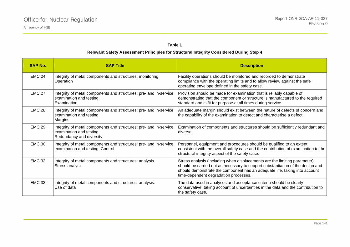
Office for Nuclear Regulation An agency of HSE
Report ONR-GDA-AR-11-027Revision 0
Page 141
Table 1
Relevant Safety Assessment Principles for Structural Integrity Considered During Step 4
SAP No. SAP Title Description
EMC.24 Integrity of metal components and structures: monitoring. Operation
Facility operations should be monitored and recorded to demonstrate compliance with the operating limits and to allow review against the safe operating envelope defined in the safety case.
EMC.27 Integrity of metal components and structures: pre- and in-service examination and testing. Examination
Provision should be made for examination that is reliably capable of demonstrating that the component or structure is manufactured to the required standard and is fit for purpose at all times during service.
EMC.28 Integrity of metal components and structures: pre- and in-service examination and testing. Margins
An adequate margin should exist between the nature of defects of concern and the capability of the examination to detect and characterise a defect.
EMC.29 Integrity of metal components and structures: pre- and in-service examination and testing. Redundancy and diversity
Examination of components and structures should be sufficiently redundant and diverse.
EMC.30 Integrity of metal components and structures: pre- and in-service examination and testing. Control
Personnel, equipment and procedures should be qualified to an extent consistent with the overall safety case and the contribution of examination to the structural integrity aspect of the safety case.
EMC.32 Integrity of metal components and structures: analysis. Stress analysis
Stress analysis (including when displacements are the limiting parameter) should be carried out as necessary to support substantiation of the design and should demonstrate the component has an adequate life, taking into account time-dependent degradation processes.
EMC.33
Integrity of metal components and structures: analysis. Use of data
The data used in analyses and acceptance criteria should be clearly conservative, taking account of uncertainties in the data and the contribution to the safety case.

Office for Nuclear Regulation An agency of HSE
Report ONR-GDA-AR-11-027Revision 0
Page 142
Table 1
Relevant Safety Assessment Principles for Structural Integrity Considered During Step 4
SAP No. SAP Title Description
EMC.34 Integrity of metal components and structures: analysis. Defect sizes
Where high reliability is required for components and structures and where otherwise appropriate, the sizes of crack-like defects of structural concern should be calculated using verified and validated fracture mechanics methods with verified application.
EAD.1 Ageing and degradation. Safe working life
The safe working life of structures, systems and components that are important to safety should be evaluated and defined at the design stage.
EAD.2 Ageing and degradation. Lifetime margins
Adequate margins should exist throughout the life of a facility to allow for the effects of materials ageing and degradation processes on structures, systems and components that are important to safety.
EAD.3 Ageing and degradation. Periodic measurement of material properties
Where material properties could change with time and affect safety, provision should be made for periodic measurement of the properties.
EAD.4 Ageing and degradation. Periodic measurement of parameters
Where parameters relevant to the design of plant could change with time and affect safety, provision should be made for their periodic measurement.
ECS.1 Safety classification and standards. Safety categorisation
The safety functions to be delivered within the facility, both during normal operation and in the event of a fault or accident, should be categorised based on their significance with regard to safety.
ECS.2 Safety classification and standards. Safety classification of structures, systems and components
Structures, systems and components that have to deliver safety functions should be identified and classified on the basis of those functions and their significance with regard to safety.
ECS.3
Safety classification and standards. Standards Structures, systems and components that are important to safety should be designed, manufactured, constructed, installed, commissioned, quality assured, maintained, tested and inspected to the appropriate standards.
EPS.4 Pressure systems: Overpressure protection Overpressure protection should be consistent with any pressure-temperature limits of operation.
Office for Nuclear Regulation An agency of HSE
Report ONR-GDA-AR-11-027Revision 0
Page 143

Office for Nuclear Regulation An agency of HSE
Report ONR-GDA-AR-11-027Revision 0
Page 144
Table 2
Main Parts of UK EPR PCSR Relevant to Structural Integrity Assessment
UK EPR PCSR Sub-Chapter
Number Sub-Chapter Title
Chapter 3. General Design and Safety Aspects
3.1 General Safety Principles
3.2 Classification of Structures, Equipment and Systems
3.4 Mechanical Systems and Components. In particular: 1.1 Design Transients 1.2 Loading Specification 1.5 Overpressure Protection Analyses 3.1 Version of the RCC-M Used 3.2 Load Combinations, Transients and Stress Limits 6. Reactor Pressure Vessel - Lower Internals
3.8 Codes and Standards used in the EPR Design. In Particular: 2. Technical Code for Mechanical Equipment (RCC-M)
Chapter 5. Reactor Coolant System and Associated Systems
5.0 Safety Requirements
5.1 Description of the Reactor Coolant System
5.2 Integrity of the Reactor Coolant Pressure Boundary (RCPB). Including: 3. Break Preclusion of the Reactor Coolant Pipework 6. Requirements Applied to “Non Breakable” Components 7. Comparison of Requirements for break Preclusion / Non-Breakable Components with UK Requirements for IOF (Section 7 added in June 2009 edition of PCSR)
5.3 Reactor Vessel
5.4 Components and Systems Sizing
Chapter 6 Containment and Safeguard Systems
6.1 Materials
6.3 Safety Injection System (for the accumulators)
Chapter 10 Main Steam and Feedwater Lines
10.3 Main Steam System (safety classified part)
10.5 Implementation of the Break Preclusion Principle for the Main Steam Lines Inside and Outside the Containment
Chapter 13 Hazards Protection
13.2 Internal Hazards Protection. In particular: 2. Protection Against Pipework Leaks and Breaks 4. Protection Against Missiles (especially 4.2.2.1.4 for RCP flywheels)
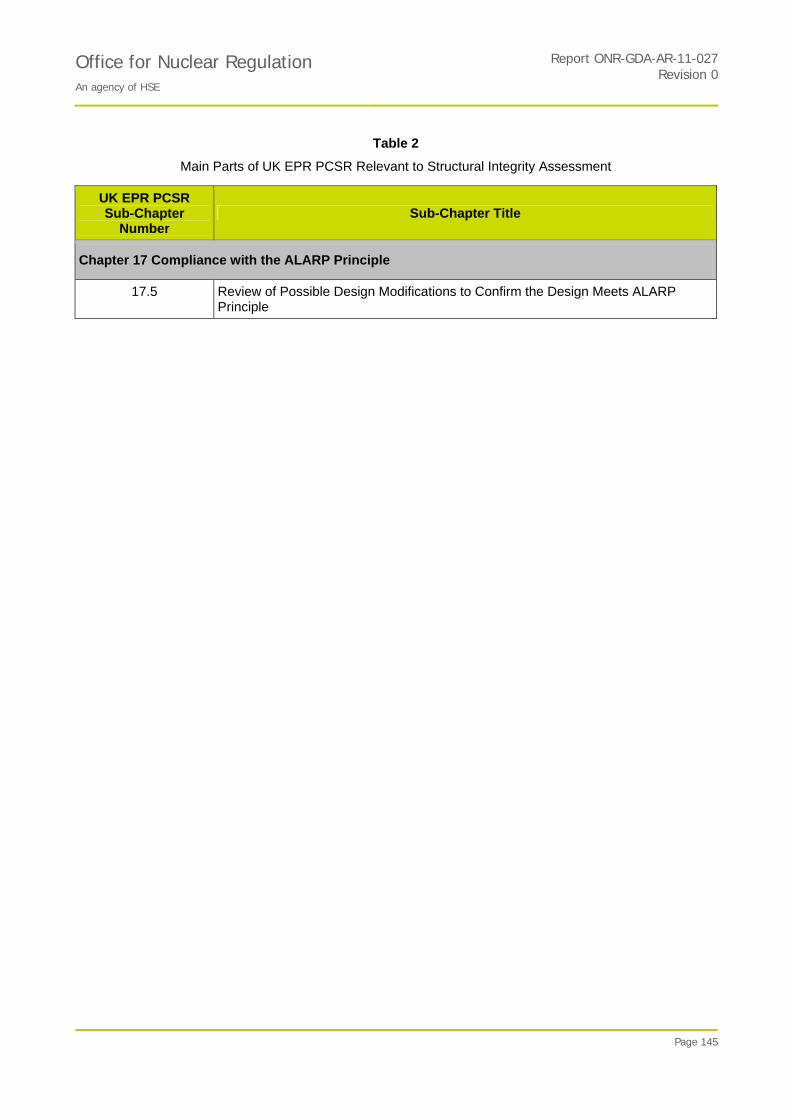
Office for Nuclear Regulation An agency of HSE
Report ONR-GDA-AR-11-027Revision 0
Page 145
Table 2
Main Parts of UK EPR PCSR Relevant to Structural Integrity Assessment
UK EPR PCSR Sub-Chapter
Number Sub-Chapter Title
Chapter 17 Compliance with the ALARP Principle
17.5 Review of Possible Design Modifications to Confirm the Design Meets ALARP Principle
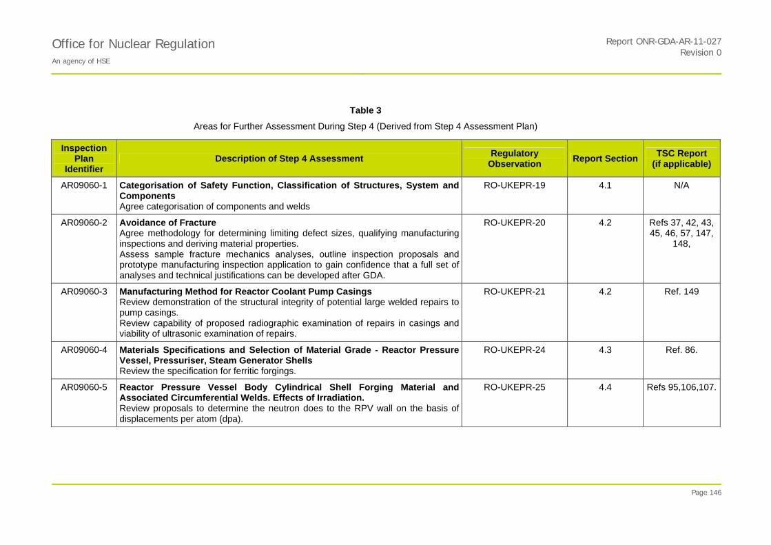
Office for Nuclear Regulation An agency of HSE
Report ONR-GDA-AR-11-027Revision 0
Page 146
Table 3
Areas for Further Assessment During Step 4 (Derived from Step 4 Assessment Plan)
Inspection Plan
Identifier Description of Step 4 Assessment
Regulatory Observation
Report SectionTSC Report
(if applicable)
AR09060-1 Categorisation of Safety Function, Classification of Structures, System and Components Agree categorisation of components and welds
RO-UKEPR-19 4.1 N/A
AR09060-2 Avoidance of Fracture Agree methodology for determining limiting defect sizes, qualifying manufacturing inspections and deriving material properties. Assess sample fracture mechanics analyses, outline inspection proposals and prototype manufacturing inspection application to gain confidence that a full set of analyses and technical justifications can be developed after GDA.
RO-UKEPR-20 4.2 Refs 37, 42, 43, 45, 46, 57, 147,
148,
AR09060-3 Manufacturing Method for Reactor Coolant Pump Casings Review demonstration of the structural integrity of potential large welded repairs to pump casings. Review capability of proposed radiographic examination of repairs in casings and viability of ultrasonic examination of repairs.
RO-UKEPR-21 4.2 Ref. 149
AR09060-4 Materials Specifications and Selection of Material Grade - Reactor Pressure Vessel, Pressuriser, Steam Generator Shells Review the specification for ferritic forgings.
RO-UKEPR-24 4.3 Ref. 86.
AR09060-5 Reactor Pressure Vessel Body Cylindrical Shell Forging Material and Associated Circumferential Welds. Effects of Irradiation. Review proposals to determine the neutron does to the RPV wall on the basis of displacements per atom (dpa).
RO-UKEPR-25 4.4
Refs 95,106,107.

Office for Nuclear Regulation An agency of HSE
Report ONR-GDA-AR-11-027Revision 0
Page 147
Table 3
Areas for Further Assessment During Step 4 (Derived from Step 4 Assessment Plan)
Inspection Plan
Identifier Description of Step 4 Assessment
Regulatory Observation
Report SectionTSC Report
(if applicable)
AR09060-6 Reactor Pressure Vessel Pressure - Temperature Limit Diagrams and Low Temperature Overpressure Protection Assess the acceptability of the new methodology for calculating the P-T limit curve and judge whether it is ALARP
RO-UKEPR-28 4.5 Ref. 109
AR09060-7 RCC-M Aspects of Requirements for Design Analysis of Piping Class 1, 2 and 3 Review the design analysis equations in RCC-M for primary loads for Class 2 and Class 3 pipework Review the treatment of earthquake and other reversing dynamic loads in RCC-M.
RO-UKEPR-36 4.6.1 Ref.150
AR09060-8 Documentary Envelope for Specific Components Review the Design Specifications and a sample of the analyses of loading conditions contained within them.
RO-UKEPR-53 4.8 Ref. 133
AR09060-9 RCC-M Welding Procedures N/A 4.6.2 Ref. 120
AR09060-10 RCC-M design requirements for the pressure boundaries of pumps and valves
N/A 4.6.3
Ref. 122
AR09060-11 Review of Access for In-Service Inspection Confirm that the design has given appropriate consideration to the needs of an adequate in-service inspection.
RO-UKEPR-54 4.10 N/A
AR09060-12 Operation of Plant within Safe Limits Review the demonstration that the constructed plant will be capable of being operated within safe limits, including the role of technical specification, maintenance schedule, procedures (especially normal operation) and operating limits giving particular emphasis on operating limits for components relevant to structural integrity.
RO-UKEPR-65 4.11 N/A

Office for Nuclear Regulation An agency of HSE
Report ONR-GDA-AR-11-027Revision 0
Page 148
Table 3
Areas for Further Assessment During Step 4 (Derived from Step 4 Assessment Plan)
Inspection Plan
Identifier Description of Step 4 Assessment
Regulatory Observation
Report SectionTSC Report
(if applicable)
AR09060-13 The Use of 20MND5 Steel Review the proposal to use 20MND5 steel for parts of the pressure boundary of the steam generators and pressuriser.
N/A 4.3.3 Ref. 86
Further Assessment Identified During Step 4
n/a Environmental Effects on Fatigue Design Curves Review the need to take account of the requirements of NUREG 1.207 (effect of environment on fatigue crack growth).
N/A 4.7 N/A
n/a Generic Categorisation and Classification Issues RO-UKEPR-43 4.9 N/A
n/a Pressuriser Heater Design Consider the relevance of the recent pressuriser heater leakage seen at Sizewell B to the EPR
N/A 4.12 N/A

Office for Nuclear Regulation An agency of HSE
Report ONR-GDA-AR-11-027Revision 0
Page 149
Table 4
Reactor Pressure Vessel Materials Compositions
ASME composition
SA508 Grade 3 Class 1
2007 + 2010 Editions
(formerly SA508 Class 3) 1
UK Usage of SA508 Class 3
RPV
Forgings10 Product Analysis
16 MND 5 RPV
Beltline Region9
RCC-M 2007 M2111
Product Analysis
16 MND 5 RPV
Outside Beltline Region
RCC-M 2007 M2112
Product Analysis
RPV Beltline submerged arc
welds RCC-M 2007
S2830B
RPV non-beltline submerged arc
welds RCC-M 2007
S2830A
UK Usage of SA508 Class 3
RPV
Welds10
Carbon 0.25% max 0.2% max 0.22% max 0.22% max <0.10% <0.10% 0.15% max
Manganese 1.2 to 1.5% 1.2 to 1.5% 1.–5 - 1.6% 1.–5 - 1.6% 0.80-1.80% 0.80-1.80% 0.80% to 1.80%
Molybdenum 0.45 to 0.6% 0.45 to 0.6% 0.–3 - 0.57% 0.–3 - 0.57% 0.35-0.65% 0.35-0.65% 0.35% to 0.65%
Nickel 0.4 to 1.0% 0.4 to 0.85% 0–5 - 0.8% 0–5 - 0.8% <1.20% <1.50% 0.85% max
Sulphur 0.025% max 0.008% max 0.005% max5 0.008% max4 0.005% max6
<0.015% <0.025% 0.010% max
Phosphorus 0.025% max 0.008% max 0.008% max8 0.008% max4 <0.010% <0.025% 0.010% max
Silicon 3 0.4% max 0.3% max 0–1 - 0.3% 0–1 - 0.3% 0.15-0.60% 0.15-0.60% 0.15% to 0.60%
Chromium 0.25% max 0.15% max 0.25% max 0.25% max <0.30% <0.30% 0.15% max
Copper 0.2% max 0.08% max 0.08% max8 0.2% max4
0.10% max6 <0.07% <0.25% 0.07% max
Vanadium 0.05% max 0.01% max 0.01% max 0.01% max <0.02% <0.04% 0.01% max
Antimony - 0.008% max 0.008% max
Arsenic - 0.015% max 0.015% max
Cobalt - 0.02% max 0.03% max 0.03% max 0.020% max

Office for Nuclear Regulation An agency of HSE
Report ONR-GDA-AR-11-027Revision 0
Page 150
Table 4
Reactor Pressure Vessel Materials Compositions
ASME composition
SA508 Grade 3 Class 1
2007 + 2010 Editions
(formerly SA508 Class 3) 1
UK Usage of SA508 Class 3
RPV
Forgings10 Product Analysis
16 MND 5 RPV
Beltline Region9
RCC-M 2007 M2111
Product Analysis
16 MND 5 RPV
Outside Beltline Region
RCC-M 2007 M2112
Product Analysis
RPV Beltline submerged arc
welds RCC-M 2007
S2830B
RPV non-beltline submerged arc
welds RCC-M 2007
S2830A
UK Usage of SA508 Class 3
RPV
Welds10
Tin - 0.01% max 0.010% max
Aluminium 0.025% max 2 0.045% max 0.04% max 0.04% max
Hydrogen - 1ppm (product) max 0.8ppm7 0.8ppm7
Boron 0.003% max2
Columbium * 0.01% max2
Calcium 0.015% max2
Titanium 0.015% max2
*Columbium = Niobium NB: 1. Values in grey highlight represent information received during GDA Step 4.
2. UK precedent is to use SA508 Class 3 (now known as SA508 Grade 3 Class 1), with additional restrictions on composition, for all major primary circuit pressure vessel forgings (including secondary shells of steam generators).
3. Both ASME and RCC-M specify steel to be made using and electric furnace and vacuum-degassed. RCC-M specifically mentions the material shall be aluminium-killed.
Notes to Table 4
1. ASME A508 Specification - Supplementary Requirement S9 specifies:
- S9.1.1 Phosphorus 0.015% max product, Copper 0.1% max product or
- S9.1.2 Phosphorus 0.015% max product, Copper 0.15% max product
Office for Nuclear Regulation An agency of HSE
Report ONR-GDA-AR-11-027Revision 0
Page 151
- S9.2 Sulphur 0.015% max product
2. Element limit added since ASME Code edition used for Sizewell B
3. ASME A508 Specification - Supplementary Requirement S11 sets limit on Silicon of 0.1% max. Supplementary Specification S16 sets range of Silicon content as 0.05 to 0.15%
4. Introduced in RCC-M 2007 (Ref. 56)
5. Introduced in RCC-M 2007 and Specified in Equipment Specification for RPV: NFPMR DC 1145 Rev I, 30 Sept 2008 (Ref. 87)
6. Specified in Equipment Specification for RPV: NFPMR DC 1145 Rev I, 30 Sept 2008 (Ref. 87)
7. Technical Manufacturing Program for RPV (Ref. 91).
8. Values of phosphorus and copper are for hollow ingots: Corresponding values for solid ingots are 0.006% and 0.06%.
9. Beltline forgings with reduced Cu in the Equipment Spec are flange/nozzle shell, core shells and transition ring.
10. Values derived from Geraghty J E, ‘Structural Integrity of Sizewell B – the Way Forward’, AEA-BNES Seminar, Pressure Component Standards for APWRs, London, 16 February 1995 (Ref. 94).

Office for Nuclear Regulation An agency of HSE
Report ONR-GDA-AR-11-027Revision 0
Page 152
Table 5
Steam Generator and Pressuriser Materials Compositions
18 MND 5 Alloy Steel Forgings for
PWR Components RCC-M 2007 M2119 Product Analysis
18 MND 5 Alloy Steel
Forgings for Steam Generator Shells
RCC-M 2007 M2133 Product Analysis
18 MND 5 Alloy Steel
Ellipsoidal Domesfor Steam Generator Channel
Heads (and Pressuriser Shell)
RCC-M 2007 M2134 Product Analysis
UK Usage of SA508 Class 3 and weldsfor
Steam Generators - base material and welds8
20 MND 5 Alloy Steel Forgings for
PWR Components RCC-M 2007 M2119 Bis
Product Analysis
Carbon 0.22%max 0.22% max 0.22% max 0.2% max 0.23%max
Manganese 1.–5 - 1.6% 1.–5 - 1.6% 1.–5 - 1.6% 1–2 - 1.5% 1.–1 - 1.59%
Molybdenum 0.–3 - 0.57% 0.–3 - 0.57 0.–2 - 0.57% 0.–5 - 0.6% 0.–3 - 0.62%
Nickel 0–5 - 0.8% 0–5 - 0.8% 0–5 - 0.8% 0.4 – 1.0% 0.37 – 1.03%
Sulphur 0.008%4 0.005%6max 0.008%4 0.005%6max 0.008%[4] 0.005%6max 0.01% max 0.008%
Phosphorus 0.008%5max 0.008%5max 0.008%5max 0.005%2max for PZR
nozzles
0.012% max 0.008%
Silicon 0–1 - 0.3% 0–1 - 0.3% 0–1 - 0.3% 0.15-0.4% 0.15-0.30%
Chromium 0.25% max 0.25% max 0.25% max 0.15% max3 0.25% max
Copper 0.2%[1] 0.12% max 6 0.2%[1] 0.12% max 6 0.2%[1] 0.12% max 6 0.10%max2
0.20% max
Vanadium 0.03% max 0.03% max 0.01% max 0.03% max7
Antimony 0.01% max
Arsenic 0.02% max

Office for Nuclear Regulation An agency of HSE
Report ONR-GDA-AR-11-027Revision 0
Page 153
Table 5
Steam Generator and Pressuriser Materials Compositions
18 MND 5 Alloy Steel Forgings for
PWR Components RCC-M 2007 M2119 Product Analysis
18 MND 5 Alloy Steel
Forgings for Steam Generator Shells
RCC-M 2007 M2133 Product Analysis
18 MND 5 Alloy Steel
Ellipsoidal Domesfor Steam Generator Channel
Heads (and Pressuriser Shell)
RCC-M 2007 M2134 Product Analysis
UK Usage of SA508 Class 3 and weldsfor
Steam Generators - base material and welds8
20 MND 5 Alloy Steel Forgings for
PWR Components RCC-M 2007 M2119 Bis
Product Analysis
Cobalt
Tin 0.015% max
Aluminium 0.04% max 0.04% max 0.04% max 0.04% max
Hydrogen
NB: 1. Values in grey highlight represent information received during GDA Step 4.
2. UK precedent is to use SA508 Class 3 (now known as SA508 Grade 3 Class 1), with additional restrictions on composition, for all major primary circuit pressure vessel forgings (including secondary shells of steam generators).
3. In the latest draft of the UK EPR PCSR (Ref 2), the material for the steam generator shells is specified as 18MND5 or 20MND5 (UKEPR-0002-054 Issue 3 Draft 1 Sub-Chapter 5.4, page 32/109). 18MND5 or 20MND5 is also specified for the pressuriser (Sub-Chapter 5.4 pages 72/109).
Notes to Table 5
1. RCC-M 2004 and 2007
2 Specified in Equipment Specification for Pressuriser – AREVA Report NEER-F DC 18 Rev E, July 2009 (Ref. 89)
3. Primary side shell only, no limit set on chromium for secondary side shell
4. Introduced in RCC-M 2007
5. Introduced in RCC-M 2007 and Specified in Equipment Specification for Steam Generator – AREVA Report NFEMG DC 80 Rev. I, June 2007 (Ref. 88)
6. Specified in Equipment Specification for Steam Generator – AREVA Report NFEMG DC 80 Rev. I, June 2007 (Ref. 88)
7. RCC-M 2007: A maximum vanadium content of 0.01% can be required for parts to be cladded.

Office for Nuclear Regulation An agency of HSE
Report ONR-GDA-AR-11-027Revision 0
Page 154
8. Values derived from Geraghty J E, ‘Structural Integrity of Sizewell B – the Way Forward’, AEA-BNES Seminar, Pressure Component Standards for APWRs, London, 16 February 1995 (Ref. 94)
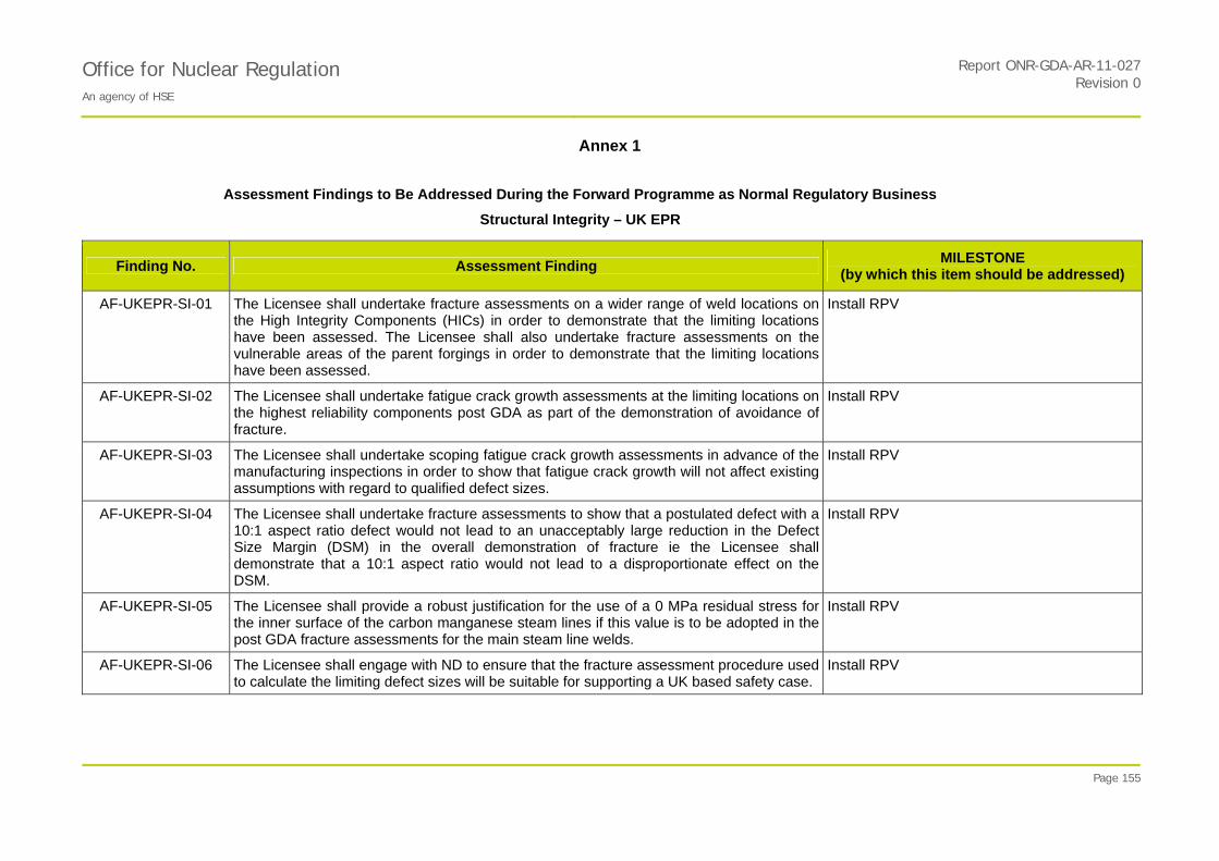
Office for Nuclear Regulation An agency of HSE
Report ONR-GDA-AR-11-027Revision 0
Annex 1
Page 155
Assessment Findings to Be Addressed During the Forward Programme as Normal Regulatory Business
Structural Integrity – UK EPR
Finding No. Assessment Finding MILESTONE
(by which this item should be addressed)
AF-UKEPR-SI-01 The Licensee shall undertake fracture assessments on a wider range of weld locations on the High Integrity Components (HICs) in order to demonstrate that the limiting locations have been assessed. The Licensee shall also undertake fracture assessments on the vulnerable areas of the parent forgings in order to demonstrate that the limiting locations have been assessed.
Install RPV
AF-UKEPR-SI-02 The Licensee shall undertake fatigue crack growth assessments at the limiting locations on the highest reliability components post GDA as part of the demonstration of avoidance of fracture.
Install RPV
AF-UKEPR-SI-03 The Licensee shall undertake scoping fatigue crack growth assessments in advance of the manufacturing inspections in order to show that fatigue crack growth will not affect existing assumptions with regard to qualified defect sizes.
Install RPV
AF-UKEPR-SI-04 The Licensee shall undertake fracture assessments to show that a postulated defect with a 10:1 aspect ratio defect would not lead to an unacceptably large reduction in the Defect Size Margin (DSM) in the overall demonstration of fracture ie the Licensee shall demonstrate that a 10:1 aspect ratio would not lead to a disproportionate effect on the DSM.
Install RPV
AF-UKEPR-SI-05 The Licensee shall provide a robust justification for the use of a 0 MPa residual stress for the inner surface of the carbon manganese steam lines if this value is to be adopted in the post GDA fracture assessments for the main steam line welds.
Install RPV
AF-UKEPR-SI-06
The Licensee shall engage with ND to ensure that the fracture assessment procedure used to calculate the limiting defect sizes will be suitable for supporting a UK based safety case.
Install RPV

Office for Nuclear Regulation An agency of HSE
Report ONR-GDA-AR-11-027Revision 0
Annex 1
Page 156
Assessment Findings to Be Addressed During the Forward Programme as Normal Regulatory Business
Structural Integrity – UK EPR
Finding No. Assessment Finding MILESTONE
(by which this item should be addressed)
AF-UKEPR-SI-07 The Licensee shall provide evidence that the capability of the NDT procedures applied during manufacture of safety-related components (but not subject to inspection qualification) is adequate for the purpose.
Install RPV
AF-UKEPR-SI-08 The Licensee shall ensure that procedures exist to take appropriate action if any planar defects are detected in forgings for the HICs since this may indicative of manufacturing problems.
Install RPV
AF-UKEPR-SI-09 The Licensee shall ensure that the Qualification Body has the necessary independence and that it provides a robust oversight of the overall qualification process.
Install RPV
AF-UKEPR-SI-10 The Licensee shall ensure that the QB is involved with review of all operator qualifications whether Levels A, B or C according to Ref. 62.
Install RPV
AF-UKEPR-SI-11
The Licensee shall ensure that the Qualification Body reviews the justification for any personnel qualification proposals (Level A) which do not involve the use of blind trails. The QB should ultimately decide, on a case-by-case basis, whether or not any blind trials are considered necessary.
Install RPV
AF-UKEPR-SI-12 The Licensee shall ensure that an adequate level of repeat inspection is proposed to assure the quality of all qualified manual ultrasonic inspections on the HICs.
Install RPV.
AF-UKEPR-SI-13 The Licensee shall ensure that, when specifying defects for qualification proposals, the evidence or judgements used to estimate the defect characteristics and probability of occurrence are recorded in sufficient detail to allow subsequent reviews.
Install RPV
AF-UKEPR-SI-14
Where certain categories of potential defects are excluded from the defect specification (e.g. transverse defects), the Licensee shall document an explicit justification for each application.
Install RPV

Office for Nuclear Regulation An agency of HSE
Report ONR-GDA-AR-11-027Revision 0
Annex 1
Page 157
Assessment Findings to Be Addressed During the Forward Programme as Normal Regulatory Business
Structural Integrity – UK EPR
Finding No. Assessment Finding MILESTONE
(by which this item should be addressed)
AF-UKEPR-SI-15 The Licensee shall ensure that details of the qualification procedure such as the number and types of defects in test pieces is defined on the basis of a good understanding of the likely weaknesses in the techniques derived from a draft Technical Justification.
Install RPV
AF-UKEPR-SI-16 The Licensee shall produce a comprehensive material data set for use during the design and assessment process, and also to support through life operation. This will need to cover all relevant data including the basic design data and the confirmatory batch and weld specific test data from the complementary fracture toughness testing programme (Section 4.2.5.3). It will need to be clearly presented such that the pedigree of the data can be traced following the literature trail with comparison to other international data sets where possible and will need to be updated through life following developments in the field and in the light of through life testing of materials subject degradation mechanisms.
Hot Operations
AF-UKEPR-SI-17 The Licensee shall ensure that the fracture testing undertaken to support tearing resistance values assumed for the main steam line welds is representative of both the main steam line thicknesses and the direction of crack propagation.
Install RPV
AF-UKEPR-SI-18 The Licensee shall ensure that the remaining ligaments in the thinner sections of the main steam line remain in a ‘J’ controlled loading state based on the postulated defect depths and allowing for 3mm of ductile tearing where an HIC case has been invoked.
Install RPV
AF-UKEPR-SI-19 The Licensee shall extend the testing which is proposed at 330oC to a lower temperature of say 50oC to confirm the upper shelf toughness at the lower end of the temperature range on those RPV forgings which will be subject to irradiation damage. This shall also apply to the welds in these regions.
Install RPV

Office for Nuclear Regulation An agency of HSE
Report ONR-GDA-AR-11-027Revision 0
Annex 1
Page 158
Assessment Findings to Be Addressed During the Forward Programme as Normal Regulatory Business
Structural Integrity – UK EPR
Finding No. Assessment Finding MILESTONE
(by which this item should be addressed)
AF-UKEPR-SI-20 The Licensee shall provide evidence that results from a previous test of a thermally aged specimen of pipework weld is representative of the narrow gap TIG welds used on the pipe to pipe welds and the narrow gap GTAW welds used between the pipework and reactor coolant pump bowl. If this is not the case, tests will need to be carried out on representative welds. In addition evidence shall be provided that thermal ageing is not a concern for the dissimilar metal weld on the main coolant loop otherwise it may be necessary to test thermally aged specimens of the weld.
Install RPV
AF-UKEPR-SI-21 The Licensee’s detailed proposals on the fracture toughness testing needed to underpin the toughness values assumed in the fracture assessments shall address the potential for batch to batch variability in the weld consumables affecting the toughness properties. Either a justification will be needed based on an understanding of the batch to batch variability of the properties supported by the testing of representative weld mock ups or testing on each batch of weld consumables.
Hot Operations
AF-UKEPR-SI-22 Where the safety case relies on stable tearing, the Licensee shall perform testing to support both the initiation value and tearing resistance values.
Install RPV
AF-UKEPR-SI-23
The Licensee shall check the competence of steelmaker(s) to comply with the RCC-M M140 qualification requirements for specific components before placing contracts for forgings.
Long Lead Item and SSC Procurement Specifications
AF-UKEPR-SI-24
The Licensee shall ensure that, since the RCC-M Part Procurement Specifications for the main vessel forgings do not provide an adequate control on the composition for all elements, additional limits on composition are specified and justified which take account of the relevant precedents specified in Tables 4 and 5 of this report.
Long Lead Item and SSC Procurement Specifications

Office for Nuclear Regulation An agency of HSE
Report ONR-GDA-AR-11-027Revision 0
Annex 1
Page 159
Assessment Findings to Be Addressed During the Forward Programme as Normal Regulatory Business
Structural Integrity – UK EPR
Finding No. Assessment Finding MILESTONE
(by which this item should be addressed)
AF-UKEPR-SI-25
The licensee shall ensure that the maximum value of nickel content in beltline welds is restricted, either by setting an upper limit not exceeding 0.85% Ni or by setting a target value with a rigorous process for reviewing the acceptability of the Ni value should the actual value be above 0.85%. This shall be completed before the generic milestone of RPV installation, although in practice it will need to be completed earlier to suit the programme for manufacture of the vessels.
Install RPV
AF-UKEPR-SI-26 The Licensee shall ensure that sample ultrasonic inspections for underclad cracking are performed during manufacture of the RPV, SGs and PZR. This shall be completed before the generic milestone of RPV installation, although in practice it will need to be completed earlier to suit the programme for manufacture of the vessels.
Install RPV
AF-UKEPR-SI-27 The licensee shall ensure that the maximum value of nickel content in 20MND5 is restricted, either by setting an upper limit not exceeding 0.8% Ni or by setting a target value with a rigorous process for reviewing the acceptability of the Ni value should the actual value be above 0.8%.
Long Lead Item and SSC Procurement Specifications
AF-UKEPR-SI-28 The Licensee shall ensure that sample ultrasonic inspections for underclad cracking are performed during manufacture on all 20MND5 components which are clad. The sample should take account of the relative lack of evidence on avoidance of underclad cracking with this material. This shall be completed before the generic milestone of RPV installation, although in practice it will need to be completed earlier to suit the programme for manufacture of the vessels.
Install RPV
AF-UKEPR-SI-29 The Licensee shall have access to an adequate database so that thermal ageing effects can be reliably predicted and, if necessary, a thermal ageing surveillance programme should be established for materials operating at temperatures experienced by the RPV outlet nozzles and the pressuriser.
Install RPV
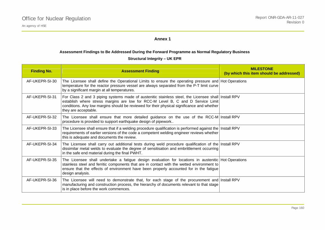
Office for Nuclear Regulation An agency of HSE
Report ONR-GDA-AR-11-027Revision 0
Annex 1
Page 160
Assessment Findings to Be Addressed During the Forward Programme as Normal Regulatory Business
Structural Integrity – UK EPR
Finding No. Assessment Finding MILESTONE
(by which this item should be addressed)
AF-UKEPR-SI-30
The Licensee shall define the Operational Limits to ensure the operating pressure and temperature for the reactor pressure vessel are always separated from the P-T limit curve by a significant margin at all temperatures.
Hot Operations
AF-UKEPR-SI-31 For Class 2 and 3 piping systems made of austenitic stainless steel, the Licensee shall establish where stress margins are low for RCC-M Level B, C and D Service Limit conditions. Any low margins should be reviewed for their physical significance and whether they are acceptable.
Install RPV
AF-UKEPR-SI-32 The Licensee shall ensure that more detailed guidance on the use of the RCC-M procedure is provided to support earthquake design of pipework..
Install RPV
AF-UKEPR-SI-33 The Licensee shall ensure that if a welding procedure qualification is performed against the requirements of earlier versions of the code a competent welding engineer reviews whether this is adequate and documents the review.
Install RPV
AF-UKEPR-SI-34
The Licensee shall carry out additional tests during weld procedure qualification of the dissimilar metal welds to evaluate the degree of sensitisation and embrittlement occurring in the safe end material during the final PWHT.
Install RPV
AF-UKEPR-SI-35
The Licensee shall undertake a fatigue design evaluation for locations in austenitic stainless steel and ferritic components that are in contact with the wetted environment to ensure that the effects of environment have been properly accounted for in the fatigue design analysis.
Hot Operations
AF-UKEPR-SI-36 The Licensee will need to demonstrate that, for each stage of the procurement and manufacturing and construction process, the hierarchy of documents relevant to that stage is in place before the work commences.
Install RPV
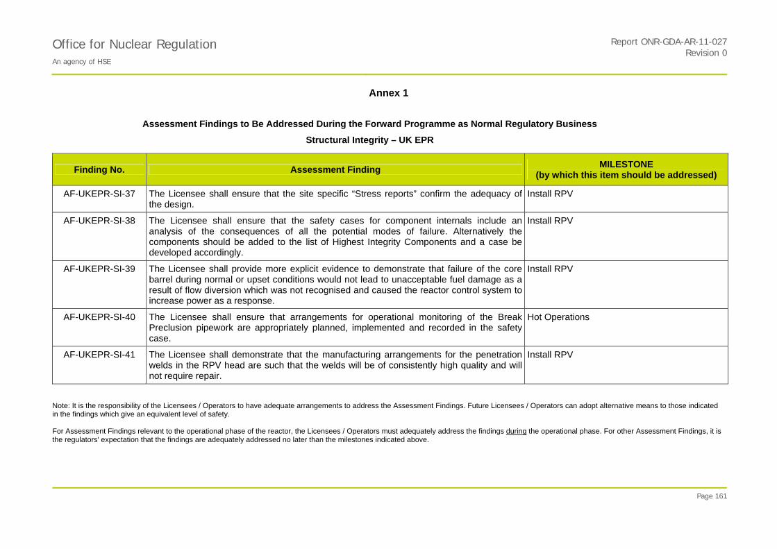
Office for Nuclear Regulation An agency of HSE
Report ONR-GDA-AR-11-027Revision 0
Annex 1
Page 161
Assessment Findings to Be Addressed During the Forward Programme as Normal Regulatory Business
Structural Integrity – UK EPR
Finding No. Assessment Finding MILESTONE
(by which this item should be addressed)
AF-UKEPR-SI-37 The Licensee shall ensure that the site specific “Stress reports” confirm the adequacy of the design.
Install RPV
AF-UKEPR-SI-38 The Licensee shall ensure that the safety cases for component internals include an analysis of the consequences of all the potential modes of failure. Alternatively the components should be added to the list of Highest Integrity Components and a case be developed accordingly.
Install RPV
AF-UKEPR-SI-39 The Licensee shall provide more explicit evidence to demonstrate that failure of the core barrel during normal or upset conditions would not lead to unacceptable fuel damage as a result of flow diversion which was not recognised and caused the reactor control system to increase power as a response.
Install RPV
AF-UKEPR-SI-40 The Licensee shall ensure that arrangements for operational monitoring of the Break Preclusion pipework are appropriately planned, implemented and recorded in the safety case.
Hot Operations
AF-UKEPR-SI-41 The Licensee shall demonstrate that the manufacturing arrangements for the penetration welds in the RPV head are such that the welds will be of consistently high quality and will not require repair.
Install RPV
Note: It is the responsibility of the Licensees / Operators to have adequate arrangements to address the Assessment Findings. Future Licensees / Operators can adopt alternative means to those indicated in the findings which give an equivalent level of safety. For Assessment Findings relevant to the operational phase of the reactor, the Licensees / Operators must adequately address the findings during the operational phase. For other Assessment Findings, it is the regulators' expectation that the findings are adequately addressed no later than the milestones indicated above.
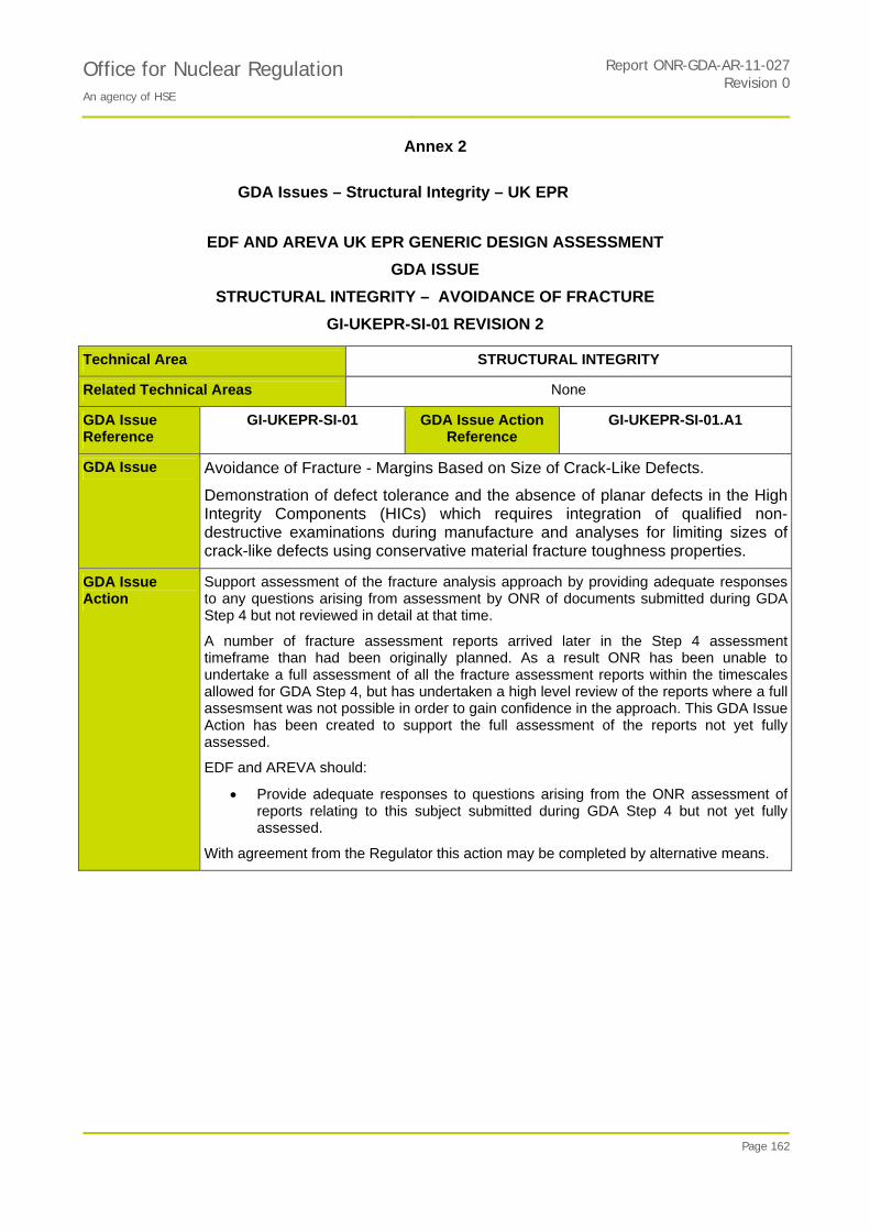
Office for Nuclear Regulation An agency of HSE
Report ONR-GDA-AR-11-027Revision 0
Annex 2
Page 162
GDA Issues – Structural Integrity – UK EPR
EDF AND AREVA UK EPR GENERIC DESIGN ASSESSMENT
GDA ISSUE
STRUCTURAL INTEGRITY – AVOIDANCE OF FRACTURE
GI-UKEPR-SI-01 REVISION 2
Technical Area STRUCTURAL INTEGRITY
Related Technical Areas None
GDA Issue Reference
GI-UKEPR-SI-01 GDA Issue Action Reference
GI-UKEPR-SI-01.A1
GDA Issue Avoidance of Fracture - Margins Based on Size of Crack-Like Defects.
Demonstration of defect tolerance and the absence of planar defects in the High Integrity Components (HICs) which requires integration of qualified non-destructive examinations during manufacture and analyses for limiting sizes of crack-like defects using conservative material fracture toughness properties.
GDA Issue Action
Support assessment of the fracture analysis approach by providing adequate responses to any questions arising from assessment by ONR of documents submitted during GDA Step 4 but not reviewed in detail at that time.
A number of fracture assessment reports arrived later in the Step 4 assessment timeframe than had been originally planned. As a result ONR has been unable to undertake a full assessment of all the fracture assessment reports within the timescales allowed for GDA Step 4, but has undertaken a high level review of the reports where a full assesmsent was not possible in order to gain confidence in the approach. This GDA Issue Action has been created to support the full assessment of the reports not yet fully assessed.
EDF and AREVA should:
Provide adequate responses to questions arising from the ONR assessment of reports relating to this subject submitted during GDA Step 4 but not yet fully assessed.
With agreement from the Regulator this action may be completed by alternative means.
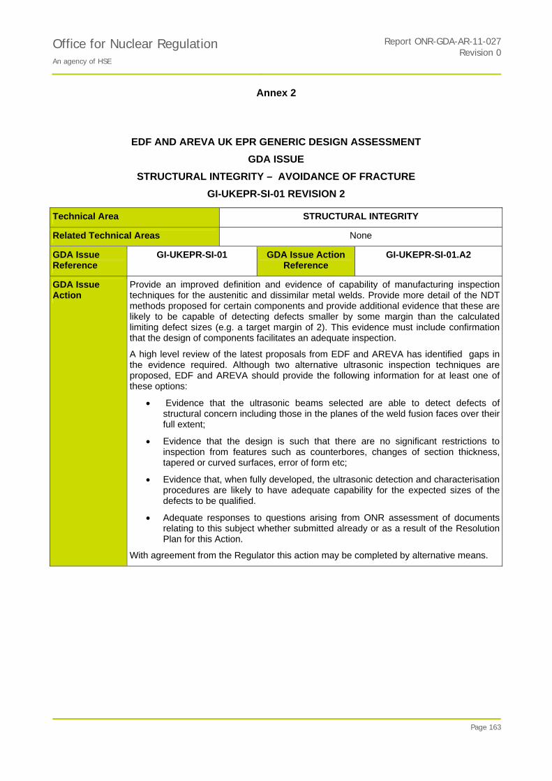
Office for Nuclear Regulation An agency of HSE
Report ONR-GDA-AR-11-027Revision 0
Annex 2
Page 163
EDF AND AREVA UK EPR GENERIC DESIGN ASSESSMENT
GDA ISSUE
STRUCTURAL INTEGRITY – AVOIDANCE OF FRACTURE
GI-UKEPR-SI-01 REVISION 2
Technical Area STRUCTURAL INTEGRITY
Related Technical Areas None
GDA Issue Reference
GI-UKEPR-SI-01 GDA Issue Action Reference
GI-UKEPR-SI-01.A2
GDA Issue Action
Provide an improved definition and evidence of capability of manufacturing inspection techniques for the austenitic and dissimilar metal welds. Provide more detail of the NDT methods proposed for certain components and provide additional evidence that these are likely to be capable of detecting defects smaller by some margin than the calculated limiting defect sizes (e.g. a target margin of 2). This evidence must include confirmation that the design of components facilitates an adequate inspection.
A high level review of the latest proposals from EDF and AREVA has identified gaps in the evidence required. Although two alternative ultrasonic inspection techniques are proposed, EDF and AREVA should provide the following information for at least one of these options:
Evidence that the ultrasonic beams selected are able to detect defects of structural concern including those in the planes of the weld fusion faces over their full extent;
Evidence that the design is such that there are no significant restrictions to inspection from features such as counterbores, changes of section thickness, tapered or curved surfaces, error of form etc;
Evidence that, when fully developed, the ultrasonic detection and characterisation procedures are likely to have adequate capability for the expected sizes of the defects to be qualified.
Adequate responses to questions arising from ONR assessment of documents relating to this subject whether submitted already or as a result of the Resolution Plan for this Action.
With agreement from the Regulator this action may be completed by alternative means.

Office for Nuclear Regulation An agency of HSE
Report ONR-GDA-AR-11-027Revision 0
Annex 2
Page 164
EDF AND AREVA UK EPR GENERIC DESIGN ASSESSMENT
GDA ISSUE
STRUCTURAL INTEGRITY – AVOIDANCE OF FRACTURE
GI-UKEPR-SI-01 REVISION 2
Technical Area STRUCTURAL INTEGRITY
Related Technical Areas None
GDA Issue Reference
GI-UKEPR-SI-01 GDA Issue Action Reference
GI-UKEPR-SI-01.A3
GDA Issue Action
Provide additional evidence of capability for the main steam line welds. Provide more detail of the NDT methods proposed for certain components and provide additional evidence that these are likely to be capable of detecting defects smaller by some margin than the calculated limiting defect sizes (e.g. a target margin of 2). This evidence must include confirmation that the design of components facilitates an adequate inspection.
A high level review of the latest proposals from EDF and AREVA has identified gaps in the evidence required and as a result EDF and AREVA should provide:
Confirmation that the weld preparation angles are such that near-specular reflection is achievable over the full height of all welds.
Evidence confirming that the effects of any potentially significant restrictions to inspection (tapered or curved surfaces, counterbores, error of form etc) are acceptable;
Evidence that, when fully developed, the ultrasonic detection and characterisation procedures are likely to have adequate capability for the expected sizes (4-5mm) of the defects to be qualified.
Adequate responses to questions arising from ONR assessment of documents relating to this subject whether submitted already or as a result of the Resolution Plan for this Action.
With agreement from the Regulator this action may be completed by alternative means.
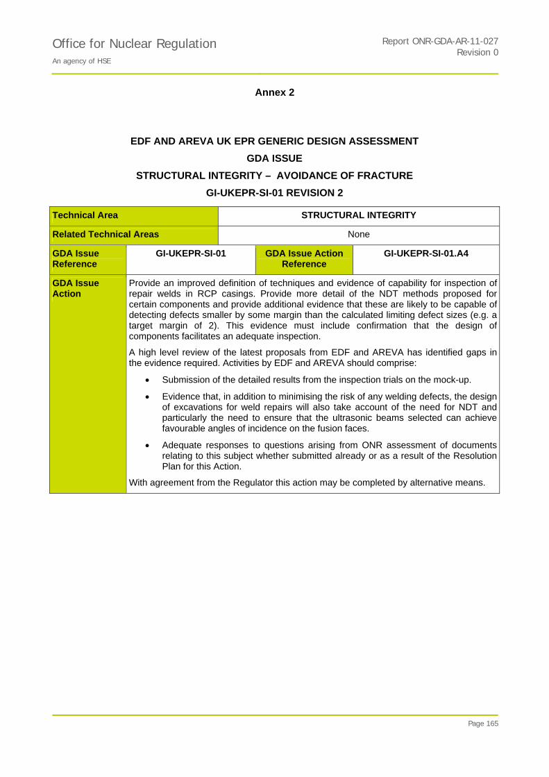
Office for Nuclear Regulation An agency of HSE
Report ONR-GDA-AR-11-027Revision 0
Annex 2
Page 165
EDF AND AREVA UK EPR GENERIC DESIGN ASSESSMENT
GDA ISSUE
STRUCTURAL INTEGRITY – AVOIDANCE OF FRACTURE
GI-UKEPR-SI-01 REVISION 2
Technical Area STRUCTURAL INTEGRITY
Related Technical Areas None
GDA Issue Reference
GI-UKEPR-SI-01 GDA Issue Action Reference
GI-UKEPR-SI-01.A4
GDA Issue Action
Provide an improved definition of techniques and evidence of capability for inspection of repair welds in RCP casings. Provide more detail of the NDT methods proposed for certain components and provide additional evidence that these are likely to be capable of detecting defects smaller by some margin than the calculated limiting defect sizes (e.g. a target margin of 2). This evidence must include confirmation that the design of components facilitates an adequate inspection.
A high level review of the latest proposals from EDF and AREVA has identified gaps in the evidence required. Activities by EDF and AREVA should comprise:
Submission of the detailed results from the inspection trials on the mock-up.
Evidence that, in addition to minimising the risk of any welding defects, the design of excavations for weld repairs will also take account of the need for NDT and particularly the need to ensure that the ultrasonic beams selected can achieve favourable angles of incidence on the fusion faces.
Adequate responses to questions arising from ONR assessment of documents relating to this subject whether submitted already or as a result of the Resolution Plan for this Action.
With agreement from the Regulator this action may be completed by alternative means.
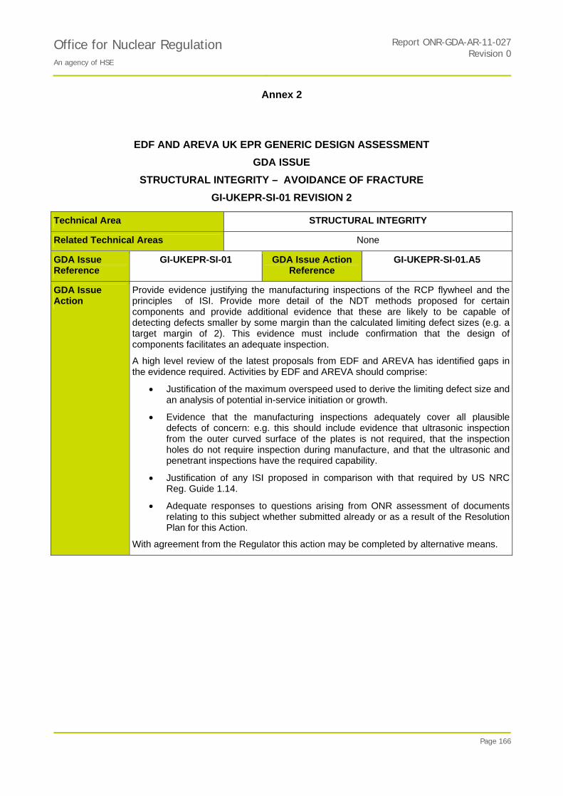
Office for Nuclear Regulation An agency of HSE
Report ONR-GDA-AR-11-027Revision 0
Annex 2
Page 166
EDF AND AREVA UK EPR GENERIC DESIGN ASSESSMENT
GDA ISSUE
STRUCTURAL INTEGRITY – AVOIDANCE OF FRACTURE
GI-UKEPR-SI-01 REVISION 2
Technical Area STRUCTURAL INTEGRITY
Related Technical Areas None
GDA Issue Reference
GI-UKEPR-SI-01 GDA Issue Action Reference
GI-UKEPR-SI-01.A5
GDA Issue Action
Provide evidence justifying the manufacturing inspections of the RCP flywheel and the principles of ISI. Provide more detail of the NDT methods proposed for certain components and provide additional evidence that these are likely to be capable of detecting defects smaller by some margin than the calculated limiting defect sizes (e.g. a target margin of 2). This evidence must include confirmation that the design of components facilitates an adequate inspection.
A high level review of the latest proposals from EDF and AREVA has identified gaps in the evidence required. Activities by EDF and AREVA should comprise:
Justification of the maximum overspeed used to derive the limiting defect size and an analysis of potential in-service initiation or growth.
Evidence that the manufacturing inspections adequately cover all plausible defects of concern: e.g. this should include evidence that ultrasonic inspection from the outer curved surface of the plates is not required, that the inspection holes do not require inspection during manufacture, and that the ultrasonic and penetrant inspections have the required capability.
Justification of any ISI proposed in comparison with that required by US NRC Reg. Guide 1.14.
Adequate responses to questions arising from ONR assessment of documents relating to this subject whether submitted already or as a result of the Resolution Plan for this Action.
With agreement from the Regulator this action may be completed by alternative means.

Office for Nuclear Regulation An agency of HSE
Report ONR-GDA-AR-11-027Revision 0
Annex 2
Page 167
EDF AND AREVA UK EPR GENERIC DESIGN ASSESSMENT
GDA ISSUE
STRUCTURAL INTEGRITY – AVOIDANCE OF FRACTURE
GI-UKEPR-SI-01 REVISION 2
Technical Area STRUCTURAL INTEGRITY
Related Technical Areas None
GDA Issue Reference
GI-UKEPR-SI-01 GDA Issue Action Reference
GI-UKEPR-SI-01.A6
GDA Issue Action
Provide additional evidence to support the technical justification of the prototype application. Provide more detail of the NDT methods proposed for certain components and provide additional evidence that these are likely to be capable of detecting defects smaller by some margin than the calculated limiting defect sizes (e.g. a target margin of 2). This evidence must include confirmation that the design of components facilitates an adequate inspection.
EDF and AREVA should provide:
An explanation of how the defects proposed in the test piece will take into account the ‘worst case defects’ and will be sufficient to test the weaknesses identified in the inspection procedure.
An explanation of how the effects of the cladding (e.g. anisotropy, uneven interface with parent material) on the inspection capability will be taken into account,
Quantification of the maximum surface profile variations (error of form) on the surfaces of the weld and cladding and justification of its acceptability.
Clarification of how surface profile variations (error of form) are controlled and checked.
Clarification of the capability likely to be achieved using the flow charts for defect characterisation.
Adequate responses to questions arising from ONR assessment of documents relating to this subject whether submitted already or as a result of the Resolution Plan for this Action.
With agreement from the Regulator this action may be completed by alternative means.

Office for Nuclear Regulation An agency of HSE
Report ONR-GDA-AR-11-027Revision 0
Annex 2
Page 168
EDF AND AREVA UK EPR GENERIC DESIGN ASSESSMENT
GDA ISSUE
STRUCTURAL INTEGRITY – AVOIDANCE OF FRACTURE
GI-UKEPR-SI-01 REVISION 2
Technical Area STRUCTURAL INTEGRITY
Related Technical Areas None
GDA Issue Reference
GI-UKEPR-SI-01 GDA Issue Action Reference
GI-UKEPR-SI-01.A7
GDA Issue Action
Provide additional evidence to confirm design and accessibility for in-service inspection (ISI). Provide more detail of the NDT methods proposed for certain components and provide additional evidence that these are likely to be capable of detecting defects smaller by some margin than the calculated limiting defect sizes (e.g. a target margin of 2). This evidence must include confirmation that the design of components facilitates an adequate inspection.
EDF and AREVA should provide:
A systematic review of the locations proposed for ISI to confirm that, as well as being physically accessible, the design of all the HIC pipework welds facilitates inspections likely to have the required capability and that there are no undue restrictions from any local design features such as counterbores or tapered surfaces.
Adequate responses to questions arising from ONR assessment of documents relating to this subject whether submitted already or as a result of the Resolution Plan for this Action.
With agreement from the Regulator this action may be completed by alternative means.

Office for Nuclear Regulation An agency of HSE
Report ONR-GDA-AR-11-027Revision 0
Annex 2
Page 169
EDF AND AREVA UK EPR GENERIC DESIGN ASSESSMENT
GDA ISSUE
STRUCTURAL INTEGRITY – RPV SURVEILLANCE SCHEME
GI-UKEPR-SI-02 REVISION 1
Technical Area STRUCTURAL INTEGRITY
Related Technical Areas None
GDA Issue Reference
GI-UKEPR-SI-02 GDA Issue Action Reference
GI-UKEPR-SI-02.A1
GDA Issue RPV Surveillance Scheme – Implications of Change in Neutron Energy Spectrum Caused by the Heavy Reflector.
Demonstration that the principles of the surveillance scheme adequately take account of the implications of the difference in neutron energy spectra between the location of the specimens and the RPV wall.
GDA Issue Action
Demonstration that the principles of the surveillance scheme adequately take account of the implications of the differences in neutron energy spectra between the location of the specimens and the RPV wall. This is expected to include the following activities:
Provision of evidence showing that the principles of the surveillance scheme adequately take account of the implications of the differences in neutron energy spectra between the location of the specimens and the RPV wall;
Justification of the concepts inherent in the analysis and interpretation of the surveillance scheme results including the treatment of uncertainties and consideration of any implications for the withdrawal scheme;
Adequate responses to questions arising from ONR assessment of documents submitted as a result of this Action.
With agreement from the Regulator this action may be completed by alternative means.
Further explanatory / background information on the GDA Issues for this topic area can be found at:
GI-UKEPR-SI-01 Revision 2 Ref. 157
GI UKEPR-SI-02 Revision 1 Ref. 158.