Embed Size (px)
Citation preview
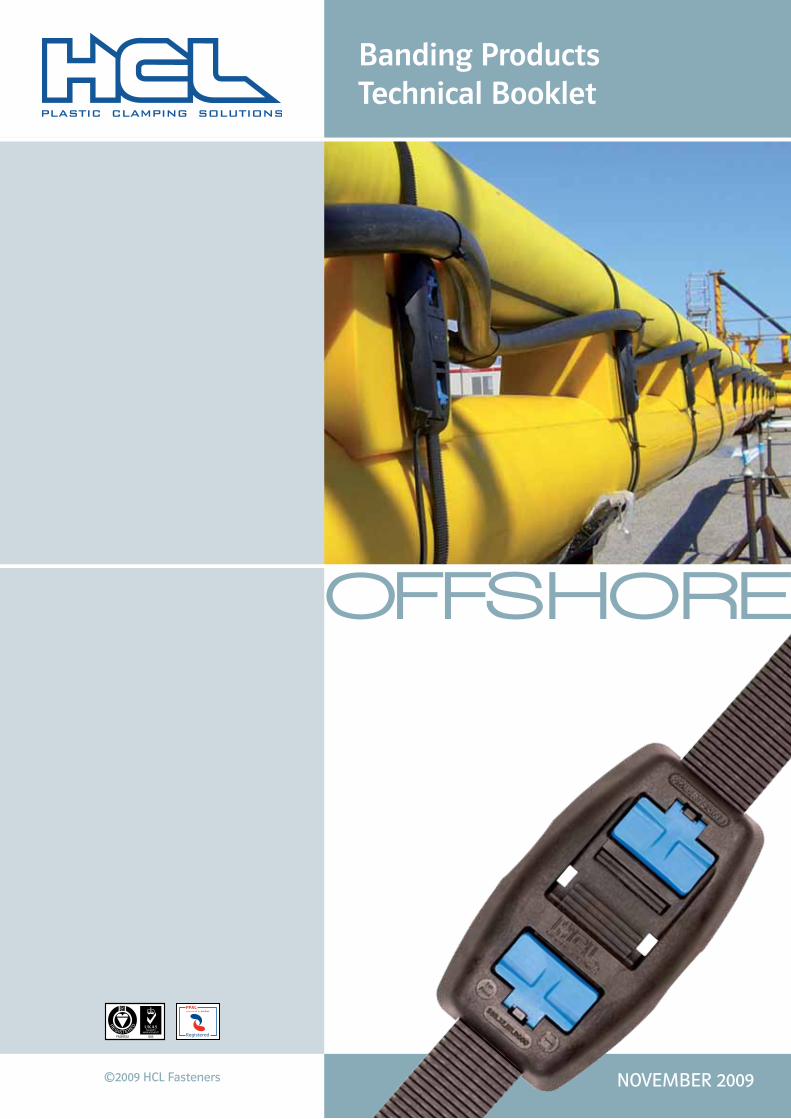
OFFSHORE
©2009 HCL Fasteners NOVEMBER 2009
Registered
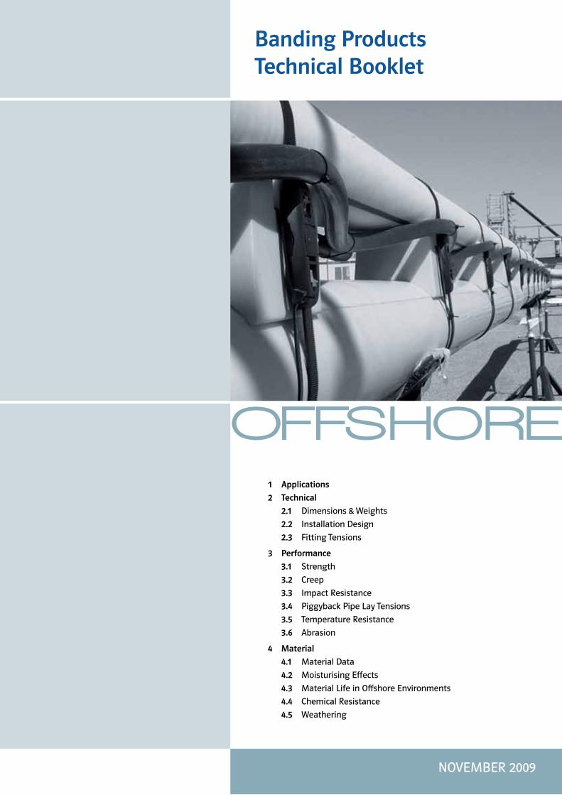
Banding Products Technical Booklet
OFFSHORE
Banding Products Technical Booklet
1 Applications
2 Technical
2.1 Dimensions & Weights
2.2 Installation Design
2.3 Fitting Tensions
3 Performance
3.1 Strength
3.2 Creep
3.3 Impact Resistance
3.4 Piggyback Pipe Lay Tensions
3.5 Temperature Resistance
3.6 Abrasion
4 Material
4.1 Material Data
4.2 Moisturising Effects
4.3 Material Life in Offshore Environments
4.4 Chemical Resistance
4.5 Weathering
NOVEMBER 2009

Banding Products – Technical Booklet
1 Applications – Introduction
OFFSHORE
The Smart Band has been used in numerous offshore projects over the past 10 years. Typical applications include sensor attachment, Piggyback pipelay, Pile protection, Umbilical and riser protection, Flotation products and subsea markers/identification.
Other suitable applications include VIV strakes, Cable attachment, Bend restrictors and Halfshell/flange shrouds for insulation. Not all customers are able to reveal project details but some have kindly allowed us to publish specific information relating to individual projects. For your interest we have listed a number here.
For full project information please visit our website www.hclfasteners.com/offshore-projects.php to find details of over 30 projects worldwide.
Tombua Landan Project Client: Acergy
Milford Haven Cathodic Protection ProjectClient: Corrosion Control Services Ltd
Erskine Project Client: Technip UK Ltd
Kashagan Experimental Project Client: Cybernetix and Saipem
Vincent Project Client: Technip Subsea 7 Asia Pacific
Port Waratah Coal Terminal Project Client: Denso (Australia) Pty Ltd
Enfield Phase 2 Project Client: Technip Oceania Pty
Norpac Enterprises ProjectClient: Norpac Enterprises
Doosan Babcock Energy Project Client: Doosan Babcock Energy
1 Applications – Introduction
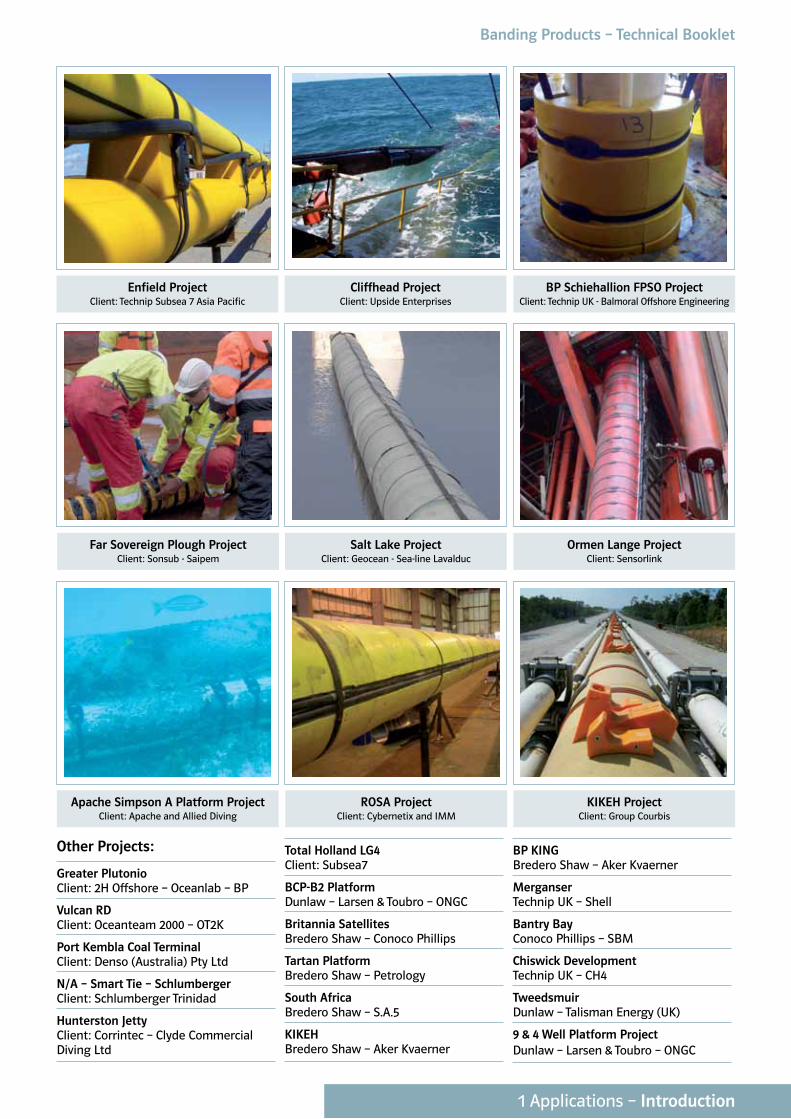
Far Sovereign Plough Project Client: Sonsub - Saipem
Salt Lake Project Client: Geocean - Sea-line Lavalduc
Ormen Lange Project Client: Sensorlink
Apache Simpson A Platform Project Client: Apache and Allied Diving
ROSA Project Client: Cybernetix and IMM
KIKEH Project Client: Group Courbis
BP Schiehallion FPSO Project Client: Technip UK - Balmoral Offshore Engineering
Cliffhead Project Client: Upside Enterprises
Enfield Project Client: Technip Subsea 7 Asia Pacific
Other Projects:
Greater PlutonioClient: 2H Offshore – Oceanlab – BP
Vulcan RD Client: Oceanteam 2000 – OT2K
Port Kembla Coal Terminal Client: Denso (Australia) Pty Ltd
N/A – Smart Tie – Schlumberger Client: Schlumberger Trinidad
Hunterston Jetty Client: Corrintec – Clyde Commercial Diving Ltd
Total Holland LG4 Client: Subsea7
BCP-B2 Platform Dunlaw – Larsen & Toubro – ONGC
Britannia Satellites Bredero Shaw – Conoco Phillips
Tartan Platform Bredero Shaw – Petrology
South Africa Bredero Shaw – S.A.5
KIKEH Bredero Shaw – Aker Kvaerner
BP KING Bredero Shaw – Aker Kvaerner
Merganser Technip UK – Shell
Bantry Bay Conoco Phillips – SBM
Chiswick Development Technip UK – CH4
Tweedsmuir Dunlaw – Talisman Energy (UK)
9 & 4 Well Platform Project Dunlaw – Larsen & Toubro – ONGC
1 Applications – Introduction
Banding Products – Technical Booklet
2.1 Technical – Dimensions & Weights
OFFSHORE
2.1 Technical – Dimensions & Weights
Table 2.1.1 – Smart Tie Material Density and Weight
Band MaterialDensity Average Weight (long)
(g/cm3) / (oz/inch3) (g) / (oz)
PP (Polypropylene) 0.93 / 0.54 46.2 / 1.63
PA66 (Nylon 6.6.) 1.15 / 0.66 58.2 / 2.05
PA11 (Nylon 11) 1.04 / 0.60 52.5 / 1.85
POM (Acetal) 1.41 / 0.82 72.8 / 2.57
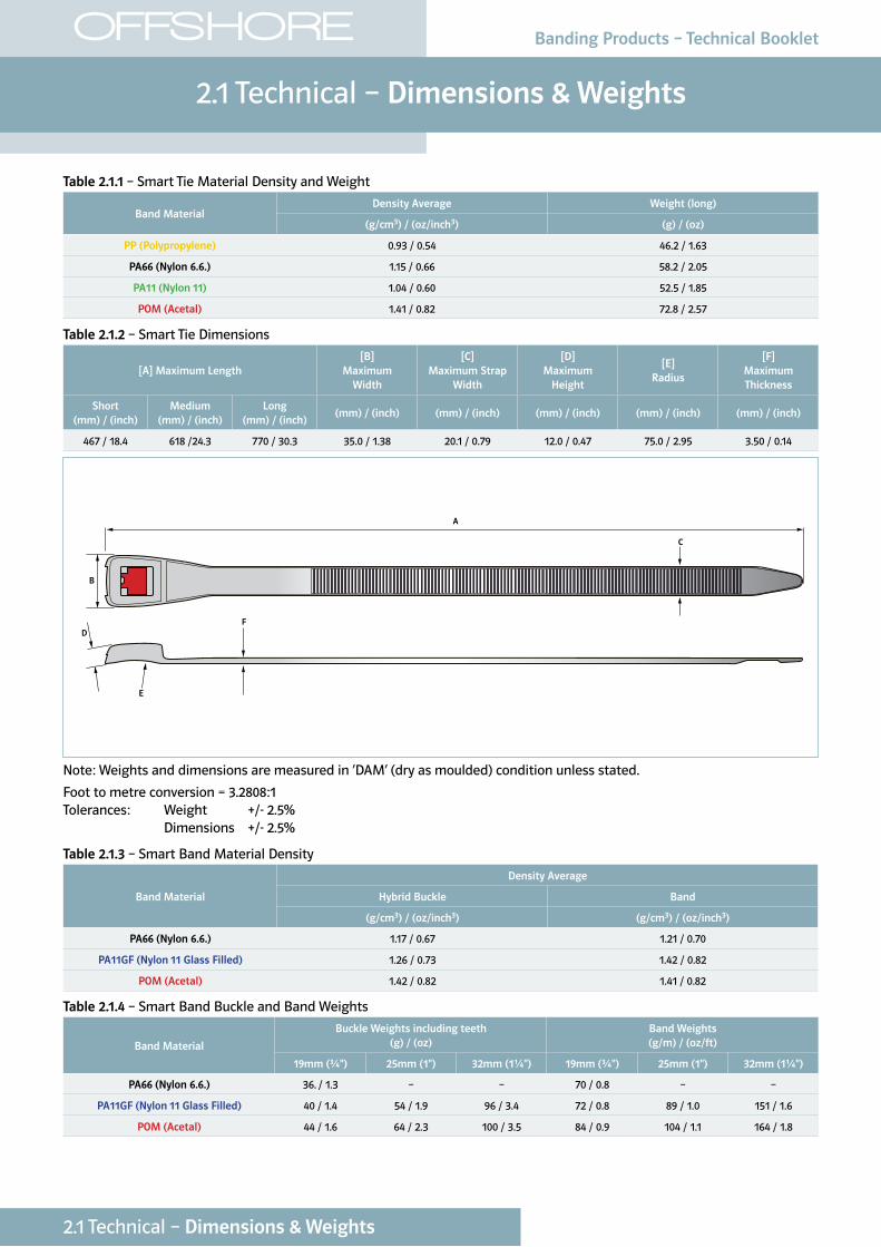
Table 2.1.2 – Smart Tie Dimensions
[A] Maximum Length[B]
Maximum Width
[C] Maximum Strap
Width
[D] Maximum
Height
[E] Radius
[F] Maximum Thickness
Short (mm) / (inch)
Medium (mm) / (inch)
Long (mm) / (inch)
(mm) / (inch) (mm) / (inch) (mm) / (inch) (mm) / (inch) (mm) / (inch)
467 / 18.4 618 /24.3 770 / 30.3 35.0 / 1.38 20.1 / 0.79 12.0 / 0.47 75.0 / 2.95 3.50 / 0.14
A
B
D
E
F
C
Note: Weights and dimensions are measured in ‘DAM’ (dry as moulded) condition unless stated.
Foot to metre conversion = 3.2808:1Tolerances: Weight +/- 2.5% Dimensions +/- 2.5%
Table 2.1.3 – Smart Band Material Density
Band Material
Density Average
Hybrid Buckle Band
(g/cm3) / (oz/inch3) (g/cm3) / (oz/inch3)
PA66 (Nylon 6.6.) 1.17 / 0.67 1.21 / 0.70
PA11GF (Nylon 11 Glass Filled) 1.26 / 0.73 1.42 / 0.82
POM (Acetal) 1.42 / 0.82 1.41 / 0.82
Table 2.1.4 – Smart Band Buckle and Band Weights
Band Material
Buckle Weights including teeth (g) / (oz)
Band Weights (g/m) / (oz/ft)
19mm (¾") 25mm (1") 32mm (1¼") 19mm (¾") 25mm (1") 32mm (1¼")
PA66 (Nylon 6.6.) 36. / 1.3 – – 70 / 0.8 – –
PA11GF (Nylon 11 Glass Filled) 40 / 1.4 54 / 1.9 96 / 3.4 72 / 0.8 89 / 1.0 151 / 1.6
POM (Acetal) 44 / 1.6 64 / 2.3 100 / 3.5 84 / 0.9 104 / 1.1 164 / 1.8
Banding Products – Technical Booklet
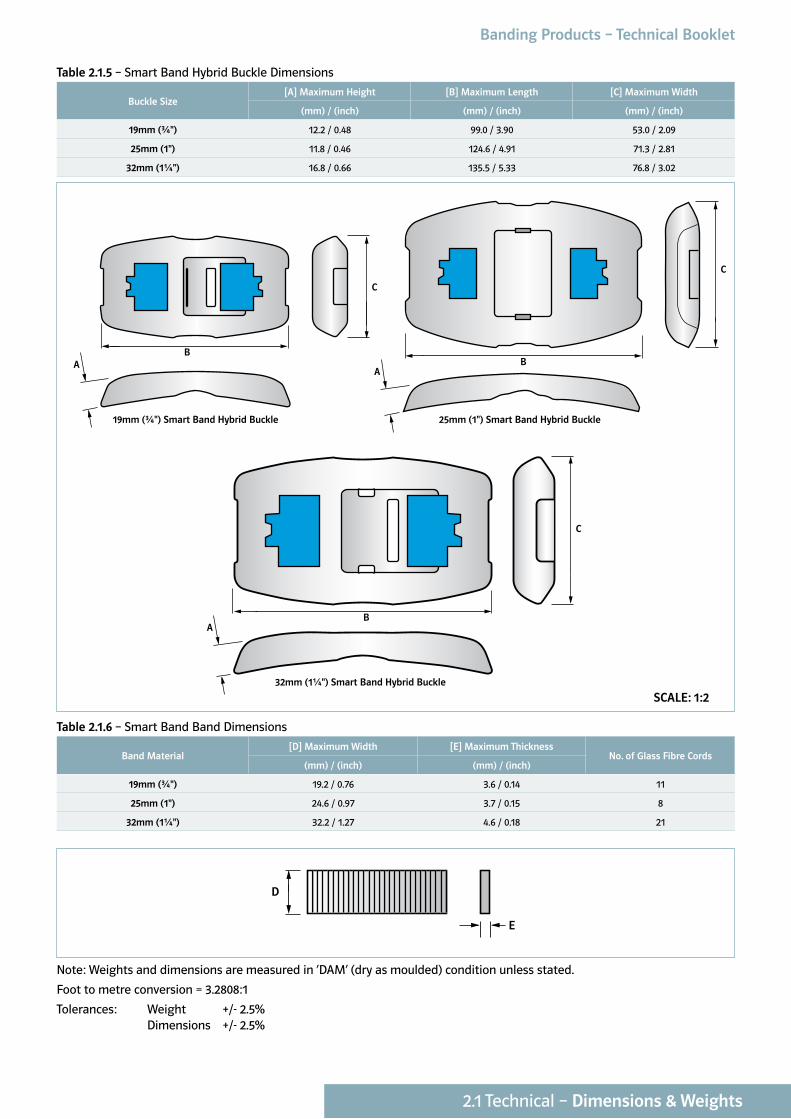
Table 2.1.5 – Smart Band Hybrid Buckle Dimensions
Buckle Size[A] Maximum Height [B] Maximum Length [C] Maximum Width
(mm) / (inch) (mm) / (inch) (mm) / (inch)
19mm (¾") 12.2 / 0.48 99.0 / 3.90 53.0 / 2.09
25mm (1") 11.8 / 0.46 124.6 / 4.91 71.3 / 2.81
32mm (1¼") 16.8 / 0.66 135.5 / 5.33 76.8 / 3.02
Table 2.1.6 – Smart Band Band Dimensions
Band Material[D] Maximum Width [E] Maximum Thickness
No. of Glass Fibre Cords(mm) / (inch) (mm) / (inch)
19mm (¾") 19.2 / 0.76 3.6 / 0.14 11
25mm (1") 24.6 / 0.97 3.7 / 0.15 8
32mm (1¼") 32.2 / 1.27 4.6 / 0.18 21
D
E
Note: Weights and dimensions are measured in ‘DAM’ (dry as moulded) condition unless stated.
Foot to metre conversion = 3.2808:1
Tolerances: Weight +/- 2.5% Dimensions +/- 2.5%
C
AB
C
AB
C
AB
25mm (1") Smart Band Hybrid Buckle
C
AB
C
AB
C
AB
32mm (1¼") Smart Band Hybrid Buckle
C
AB
C
AB
C
AB
19mm (¾") Smart Band Hybrid Buckle
SCALE: 1:2
2.1 Technical – Dimensions & Weights
Banding Products – Technical Booklet
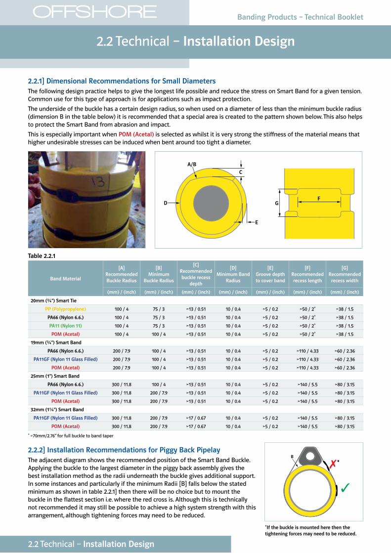
2.2.1] Dimensional Recommendations for Small DiametersThe following design practice helps to give the longest life possible and reduce the stress on Smart Band for a given tension. Common use for this type of approach is for applications such as impact protection.
The underside of the buckle has a certain design radius, so when used on a diameter of less than the minimum buckle radius (dimension B in the table below) it is recommended that a special area is created to the pattern shown below. This also helps to protect the Smart Band from abrasion and impact.
This is especially important when POM (Acetal) is selected as whilst it is very strong the stiffness of the material means that higher undesirable stresses can be induced when bent around too tight a diameter.
GF
D
E
A/B
C
Table 2.2.1
Band Material
[A] Recommended Buckle Radius
[B]Minimum
Buckle Radius
[C]Recommended buckle recess
depth
[D]Minimum Band
Radius
[E]Groove depth to cover band
[F]Recommended recess length
[G]Recommended
recess width
(mm) / (inch) (mm) / (inch) (mm) / (inch) (mm) / (inch) (mm) / (inch) (mm) / (inch) (mm) / (inch)
20mm (¾") Smart Tie
PP (Polypropylene) 100 / 4 75 / 3 >13 / 0.51 10 / 0.4 >5 / 0.2 >50 / 2* >38 / 1.5
PA66 (Nylon 6.6.) 100 / 4 75 / 3 >13 / 0.51 10 / 0.4 >5 / 0.2 >50 / 2* >38 / 1.5
PA11 (Nylon 11) 100 / 4 75 / 3 >13 / 0.51 10 / 0.4 >5 / 0.2 >50 / 2* >38 / 1.5
POM (Acetal) 100 / 4 100 / 4 >13 / 0.51 10 / 0.4 >5 / 0.2 >50 / 2* >38 / 1.5
19mm (¾") Smart Band
PA66 (Nylon 6.6.) 200 / 7.9 100 / 4 >13 / 0.51 10 / 0.4 >5 / 0.2 >110 / 4.33 >60 / 2.36
PA11GF (Nylon 11 Glass Filled) 200 / 7.9 100 / 4 >13 / 0.51 10 / 0.4 >5 / 0.2 >110 / 4.33 >60 / 2.36
POM (Acetal) 200 / 7.9 100 / 4 >13 / 0.51 10 / 0.4 >5 / 0.2 >110 / 4.33 >60 / 2.36
25mm (1") Smart Band
PA66 (Nylon 6.6.) 300 / 11.8 100 / 4 >13 / 0.51 10 / 0.4 >5 / 0.2 >140 / 5.5 >80 / 3.15
PA11GF (Nylon 11 Glass Filled) 300 / 11.8 200 / 7.9 >13 / 0.51 10 / 0.4 >5 / 0.2 >140 / 5.5 >80 / 3.15
POM (Acetal) 300 / 11.8 200 / 7.9 >13 / 0.51 10 / 0.4 >5 / 0.2 >140 / 5.5 >80 / 3.15
32mm (1¼") Smart Band
PA11GF (Nylon 11 Glass Filled) 300 / 11.8 200 / 7.9 >17 / 0.67 10 / 0.4 >5 / 0.2 >140 / 5.5 >80 / 3.15
POM (Acetal) 300 / 11.8 200 / 7.9 >17 / 0.67 10 / 0.4 >5 / 0.2 >140 / 5.5 >80 / 3.15
* >70mm/2.76” for full buckle to band taper
2.2.2] Installation Recommendations for Piggy Back PipelayThe adjacent diagram shows the recommended position of the Smart Band Buckle. Applying the buckle to the largest diameter in the piggy back assembly gives the best installation method as the radii underneath the buckle gives additional support. In some instances and particularly if the minimum Radii [B] falls below the stated minimum as shown in table 2.2.1] then there will be no choice but to mount the buckle in the flattest section i.e. where the red cross is. Although this is technically not recommended it may still be possible to achieve a high system strength with this arrangement, although tightening forces may need to be reduced.
2.2 Technical – Installation Design
OFFSHORE
2.2 Technical – Installation Design
Banding Products – Technical Booklet
✓
✗B
*If the buckle is mounted here then the tightening forces may need to be reduced.
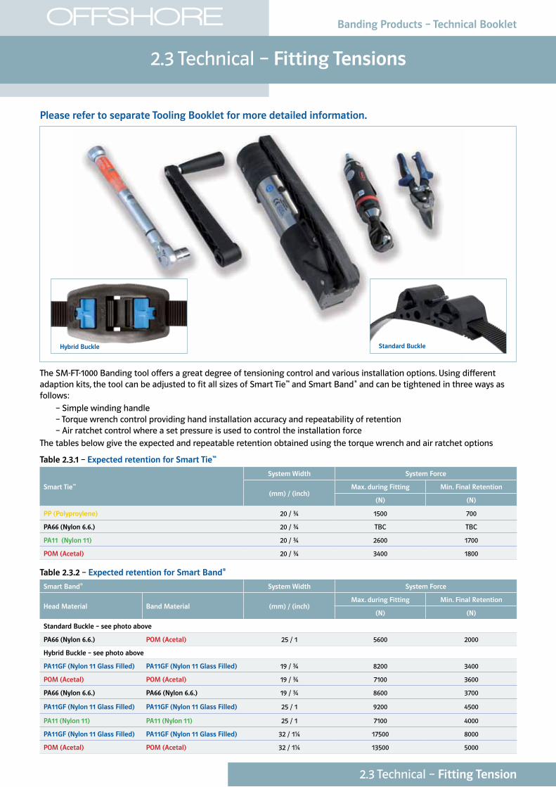
Please refer to separate Tooling Booklet for more detailed information.
The SM-FT-1000 Banding tool offers a great degree of tensioning control and various installation options. Using different adaption kits, the tool can be adjusted to fit all sizes of Smart Tie™ and Smart Band® and can be tightened in three ways as follows: – Simple winding handle – Torque wrench control providing hand installation accuracy and repeatability of retention – Air ratchet control where a set pressure is used to control the installation forceThe tables below give the expected and repeatable retention obtained using the torque wrench and air ratchet options
Table 2.3.1 – Expected retention for Smart Tie™
Smart Tie™
System Width System Force
(mm) / (inch) Max. during Fitting Min. Final Retention
(N) (N)
PP (Polyproylene) 20 / ¾ 1500 700
PA66 (Nylon 6.6.) 20 / ¾ TBC TBC
PA11 (Nylon 11) 20 / ¾ 2600 1700
POM (Acetal) 20 / ¾ 3400 1800
Table 2.3.2 – Expected retention for Smart Band®
Smart Band® System Width System Force
Head Material Band Material (mm) / (inch) Max. during Fitting Min. Final Retention
(N) (N)
Standard Buckle – see photo above
PA66 (Nylon 6.6.) POM (Acetal) 25 / 1 5600 2000
Hybrid Buckle – see photo above
PA11GF (Nylon 11 Glass Filled) PA11GF (Nylon 11 Glass Filled) 19 / ¾ 8200 3400
POM (Acetal) POM (Acetal) 19 / ¾ 7100 3600
PA66 (Nylon 6.6.) PA66 (Nylon 6.6.) 19 / ¾ 8600 3700
PA11GF (Nylon 11 Glass Filled) PA11GF (Nylon 11 Glass Filled) 25 / 1 9200 4500
PA11 (Nylon 11) PA11 (Nylon 11) 25 / 1 7100 4000
PA11GF (Nylon 11 Glass Filled) PA11GF (Nylon 11 Glass Filled) 32 / 1¼ 17500 8000
POM (Acetal) POM (Acetal) 32 / 1¼ 13500 5000
Standard BuckleHybrid Buckle
2.3 Technical – Fitting Tensions
OFFSHORE
2.3 Technical – Fitting Tension
Banding Products – Technical Booklet
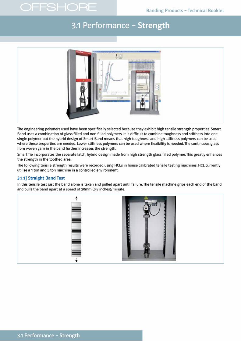
The engineering polymers used have been specifically selected because they exhibit high tensile strength properties. Smart Band uses a combination of glass filled and non-filled polymers. It is difficult to combine toughness and stiffness into one single polymer but the hybrid design of Smart Band means that high toughness and high stiffness polymers can be used where these properties are needed. Lower stiffness polymers can be used where flexibility is needed. The continuous glass fibre woven yarn in the band further increases the strength.
Smart Tie incorporates the separate latch, hybrid design made from high strength glass filled polymer. This greatly enhances the strength in the toothed area.
The following tensile strength results were recorded using HCL’s in house calibrated tensile testing machines. HCL currently utilise a 1 ton and 5 ton machine in a controlled environment.
3.1.1] Straight Band TestIn this tensile test just the band alone is taken and pulled apart until failure. The tensile machine grips each end of the band and pulls the band apart at a speed of 20mm (0.8 inches)/minute.
3.1 Performance – Strength
OFFSHORE
3.1 Performance – Strength
Banding Products – Technical Booklet
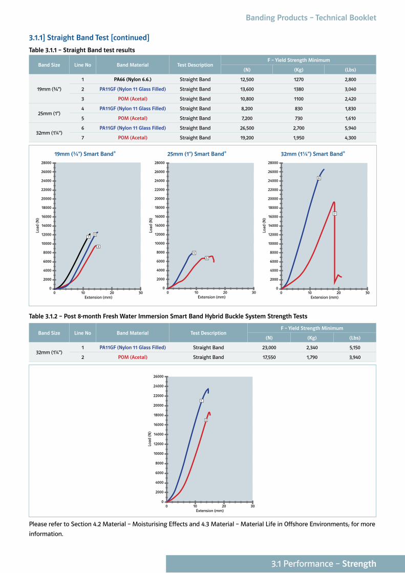
3.1.1] Straight Band Test [continued]
Table 3.1.1 – Straight Band test results
Band Size Line No Band Material Test DescriptionF – Yield Strength Minimum
(N) (Kg) (Lbs)
19mm (¾")
1 PA66 (Nylon 6.6.) Straight Band 12,500 1270 2,800
2 PA11GF (Nylon 11 Glass Filled) Straight Band 13,600 1380 3,040
3 POM (Acetal) Straight Band 10,800 1100 2,420
25mm (1")4 PA11GF (Nylon 11 Glass Filled) Straight Band 8,200 830 1,830
5 POM (Acetal) Straight Band 7,200 730 1,610
32mm (1¼")6 PA11GF (Nylon 11 Glass Filled) Straight Band 26,500 2,700 5,940
7 POM (Acetal) Straight Band 19,200 1,950 4,300
Table 3.1.2 – Post 8-month Fresh Water Immersion Smart Band Hybrid Buckle System Strength Tests
Band Size Line No Band Material Test DescriptionF – Yield Strength Minimum
(N) (Kg) (Lbs)
32mm (1¼")1 PA11GF (Nylon 11 Glass Filled) Straight Band 23,000 2,340 5,150
2 POM (Acetal) Straight Band 17,550 1,790 3,940
0 10 20 300
2000
4000
6000
8000
10000
12000
14000
16000
18000
20000
22000
26000
24000
Extension (mm)
Load
(N)
1
2
Please refer to Section 4.2 Material – Moisturising Effects and 4.3 Material – Material Life in Offshore Environments; for more
information.
0 10 20 300
2000
4000
6000
8000
10000
12000
14000
16000
18000
20000
22000
28000
26000
24000
Extension (mm)
Load
(N)
4
5
0 10 20 300
2000
4000
6000
8000
10000
12000
14000
16000
18000
20000
22000
28000
24000
26000
Extension (mm)
Load
(N)
6
7
0 10 20 300
2000
4000
6000
8000
10000
12000
14000
16000
18000
20000
22000
28000
26000
24000
Extension (mm)
Load
(N)
1
3
2
19mm (¾") Smart Band® 25mm (1") Smart Band® 32mm (1¼") Smart Band®
3.1 Performance – Strength
Banding Products – Technical Booklet
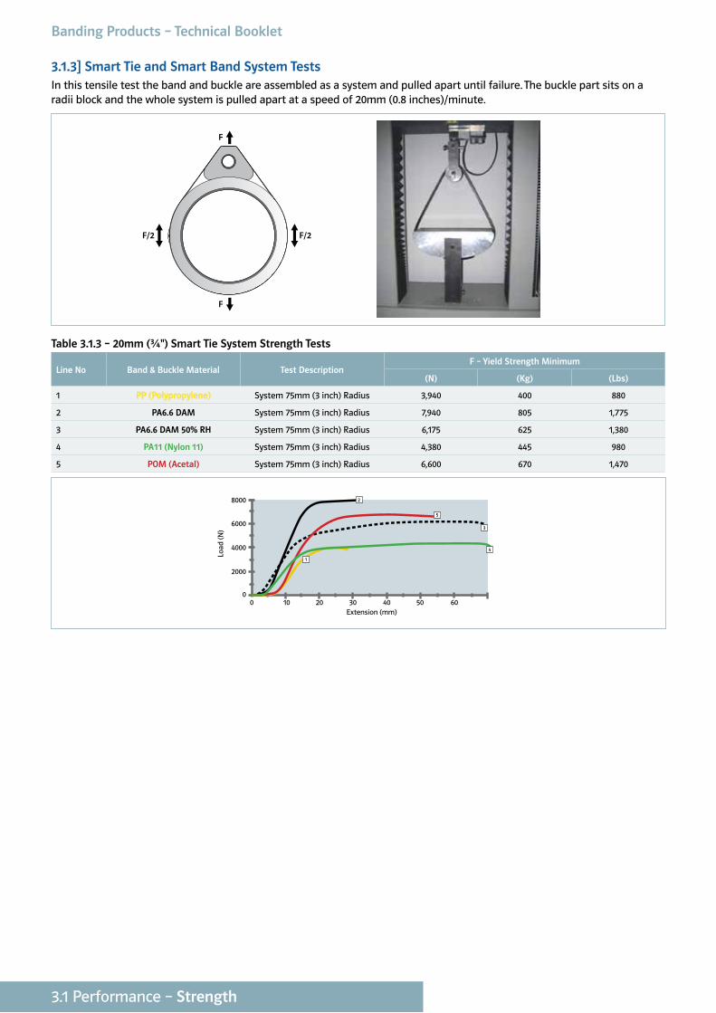
3.1.3] Smart Tie and Smart Band System TestsIn this tensile test the band and buckle are assembled as a system and pulled apart until failure. The buckle part sits on a radii block and the whole system is pulled apart at a speed of 20mm (0.8 inches)/minute.
Table 3.1.3 – 20mm (¾") Smart Tie System Strength Tests
Line No Band & Buckle Material Test DescriptionF – Yield Strength Minimum
(N) (Kg) (Lbs)
1 PP (Polypropylene) System 75mm (3 inch) Radius 3,940 400 880
2 PA6.6 DAM System 75mm (3 inch) Radius 7,940 805 1,775
3 PA6.6 DAM 50% RH System 75mm (3 inch) Radius 6,175 625 1,380
4 PA11 (Nylon 11) System 75mm (3 inch) Radius 4,380 445 980
5 POM (Acetal) System 75mm (3 inch) Radius 6,600 670 1,470
0 10 20 30 40 50 600
2000
4000
6000
8000
Extension (mm)
Load
(N)
1
2
3
4
5
Banding Products – Technical Booklet
3.1 Performance – Strength
F
F
F/2F/2
3.1 Performance – Strength
Banding Products – Technical Booklet
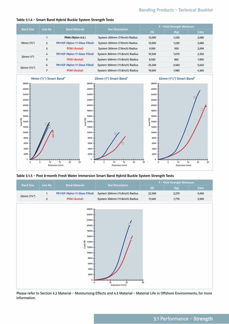
Table 3.1.4 – Smart Band Hybrid Buckle System Strength Tests
Band Size Line No Band Material Test DescriptionF – Yield Strength Minimum
(N) (Kg) (Lbs)
19mm (¾")
1 PA66 (Nylon 6.6.) System 200mm (7.9inch) Radius 12,000 1,220 2,680
2 PA11GF (Nylon 11 Glass Filled) System 200mm (7.9inch) Radius 12,000 1,220 2,680
3 POM (Acetal) System 200mm (7.9inch) Radius 9,300 950 2,090
25mm (1")4 PA11GF (Nylon 11 Glass Filled) System 300mm (11.8inch) Radius 10,500 1,070 2,350
5 POM (Acetal) System 300mm (11.8inch) Radius 8,500 860 1,900
32mm (1¼")6 PA11GF (Nylon 11 Glass Filled) System 300mm (11.8inch) Radius 25,200 2,560 5,640
7 POM (Acetal) System 300mm (11.8inch) Radius 19,500 1,980 4,360
Table 3.1.5 – Post 8-month Fresh Water Immersion Smart Band Hybrid Buckle System Strength Tests
Band Size Line No Band Material Test DescriptionF – Yield Strength Minimum
(N) (Kg) (Lbs)
32mm (1¼")1 PA11GF (Nylon 11 Glass Filled) System 300mm (11.8inch) Radius 22,300 2,270 5,000
2 POM (Acetal) System 300mm (11.8inch) Radius 17,400 1,770 3,900
0 10 20 300
2000
4000
6000
8000
10000
12000
14000
16000
18000
20000
22000
26000
24000
Extension (mm)
Load
(N)
1
2
Please refer to Section 4.2 Material – Moisturising Effects and 4.3 Material – Material Life in Offshore Environments; for more information.
0 5 10 15 20 250
2000
4000
6000
8000
10000
12000
14000
16000
18000
20000
22000
24000
26000
Extension (mm)
Load
(N)
28000
5
4
0 5 10 15 20 250
2000
4000
6000
8000
10000
12000
14000
16000
18000
20000
22000
24000
26000
Extension (mm)
Load
(N)
28000
6
7
0 5 10 15 20 250
2000
4000
6000
8000
10000
12000
14000
16000
18000
20000
22000
24000
26000
28000
Extension (mm)
Load
(N)
2
3
1
19mm (¾") Smart Band® 25mm (1") Smart Band® 32mm (1¼") Smart Band®
3.2 Performance – Creep
OFFSHORE
3.2 Performance – Creep
Banding Products – Technical Booklet
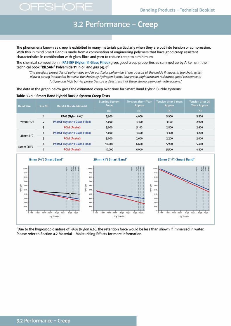
The phenomena known as creep is exhibited in many materials particularly when they are put into tension or compression. With this in mind Smart Band is made from a combination of engineering polymers that have good creep resistant characteristics in combination with glass fibre and yarn to reduce creep to a minimum.
The chemical composition in PA11GF (Nylon 11 Glass Filled) gives good creep properties as summed up by Arkema in their technical book “RILSAN® Polyamide 11 in oil and gas pg. 6”
“The excellent properties of polyamides and in particular polyamide 11 are a result of the amide linkages in the chain which allow a strong interaction between the chains by hydrogen bonds. Low creep, high abrasion resistance, good resistance to
fatigue and high barrier properties are a direct result of these strong inter-chain interactions.”
The data in the graph below gives the estimated creep over time for Smart Band Hybrid Buckle systems:
Table 3.2.1 – Smart Band Hybrid Buckle System Creep Tests
Band Size Line No Band & Buckle Material
Starting System Force
Tension after 1 Year Approx
Tension after 5 Years Approx
Tension after 25 Years Approx
(N) (N) (N) (N)
19mm (¾")
1 PA66 (Nylon 6.6.)* 5,000 4,000 3,900 3,800
2 PA11GF (Nylon 11 Glass Filled) 5,000 3,300 3,100 2,900
3 POM (Acetal) 5,000 3,100 2,800 2,600
25mm (1")4 PA11GF (Nylon 11 Glass Filled) 5,000 3,400 3,300 3,200
5 POM (Acetal) 5,000 2,600 2,200 2,000
32mm (1¼")6 PA11GF (Nylon 11 Glass Filled) 10,000 6,600 5,900 5,400
7 POM (Acetal) 10,000 6,000 5,500 4,800
*Due to the hygroscopic nature of PA66 (Nylon 6.6.), the retention force would be less than shown if immersed in water. Please refer to Section 4.2 Material – Moisturising Effects for more information.
19mm (¾") Smart Band® 25mm (1") Smart Band® 32mm (1¼") Smart Band®
0 100 1000 10000 100000 1exp6 1exp7 1exp8 1exp90
1000
2000
3000
4000
5000
6000
7000
8000
9000
10000
Log Time (s)
Forc
e (N
)
1 ye
ar
50 y
ears
5 ye
ars
10 y
ears
25 y
ears
1
2
3
0 100 1000 10000 100000 1exp6 1exp7 1exp8 1exp90
1000
2000
3000
4000
5000
6000
7000
8000
9000
10000
Log Time (s)
Forc
e (N
)
1 ye
ar
50 y
ears
5 ye
ars
10 y
ears
25 y
ears
6
7
0 100 1000 10000 100000 1exp6 1exp7 1exp8 1exp90
1000
2000
3000
4000
5000
6000
7000
8000
9000
10000
Log Time (s)
Forc
e (N
)
1 ye
ar
50 y
ears
5 ye
ars
10 y
ears
25 y
ears
4
5
Banding Products – Technical BookletOFFSHORE
3.3 Performance – Impact Resistance
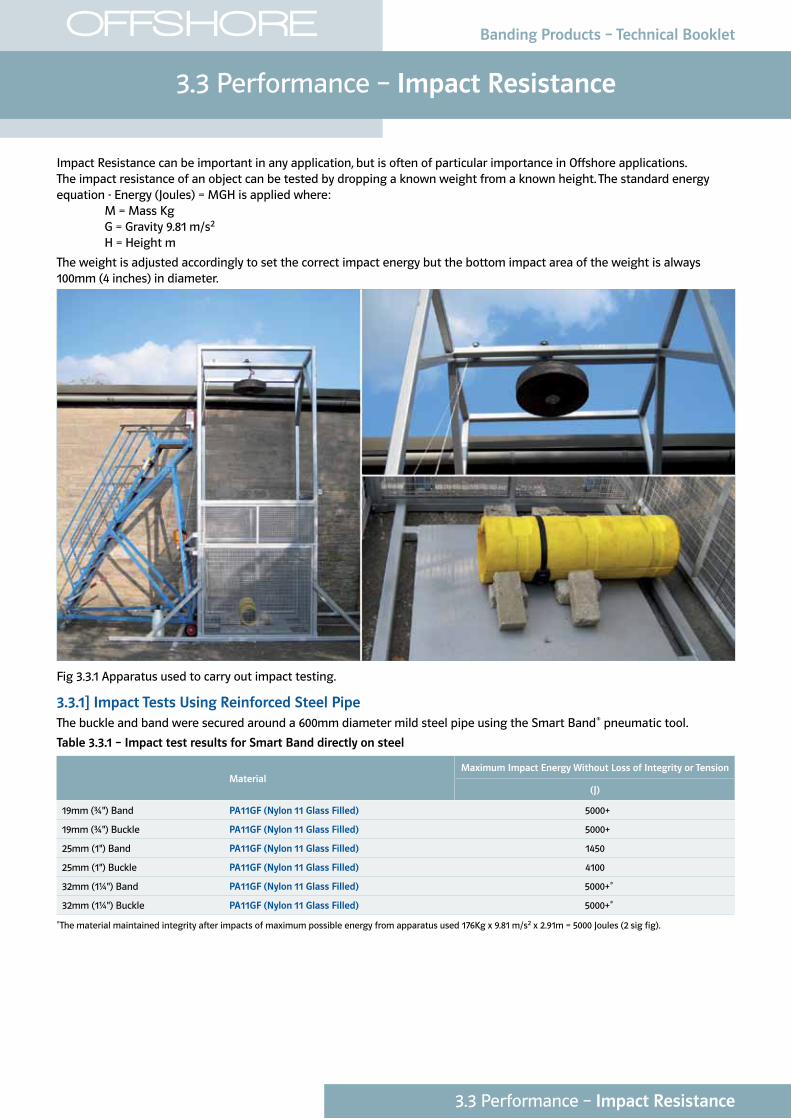
Impact Resistance can be important in any application, but is often of particular importance in Offshore applications. The impact resistance of an object can be tested by dropping a known weight from a known height. The standard energy equation - Energy (Joules) = MGH is applied where: M = Mass Kg G = Gravity 9.81 m/s2
H = Height m
The weight is adjusted accordingly to set the correct impact energy but the bottom impact area of the weight is always 100mm (4 inches) in diameter.
Fig 3.3.1 Apparatus used to carry out impact testing.
3.3.1] Impact Tests Using Reinforced Steel PipeThe buckle and band were secured around a 600mm diameter mild steel pipe using the Smart Band® pneumatic tool.
Table 3.3.1 – Impact test results for Smart Band directly on steel
MaterialMaximum Impact Energy Without Loss of Integrity or Tension
(J)
19mm (¾") Band PA11GF (Nylon 11 Glass Filled) 5000+
19mm (¾") Buckle PA11GF (Nylon 11 Glass Filled) 5000+
25mm (1") Band PA11GF (Nylon 11 Glass Filled) 1450
25mm (1") Buckle PA11GF (Nylon 11 Glass Filled) 4100
32mm (1¼") Band PA11GF (Nylon 11 Glass Filled) 5000+*
32mm (1¼") Buckle PA11GF (Nylon 11 Glass Filled) 5000+*
*The material maintained integrity after impacts of maximum possible energy from apparatus used 176Kg x 9.81 m/s2 x 2.91m = 5000 Joules (2 sig fig).
3.3 Performance – Impact Resistance
Banding Products – Technical Booklet
3.4 Performance – Piggyback Pipe Lay Tensions
OFFSHORE
3.4 Performance – Piggyback Pipe Lay Tensions
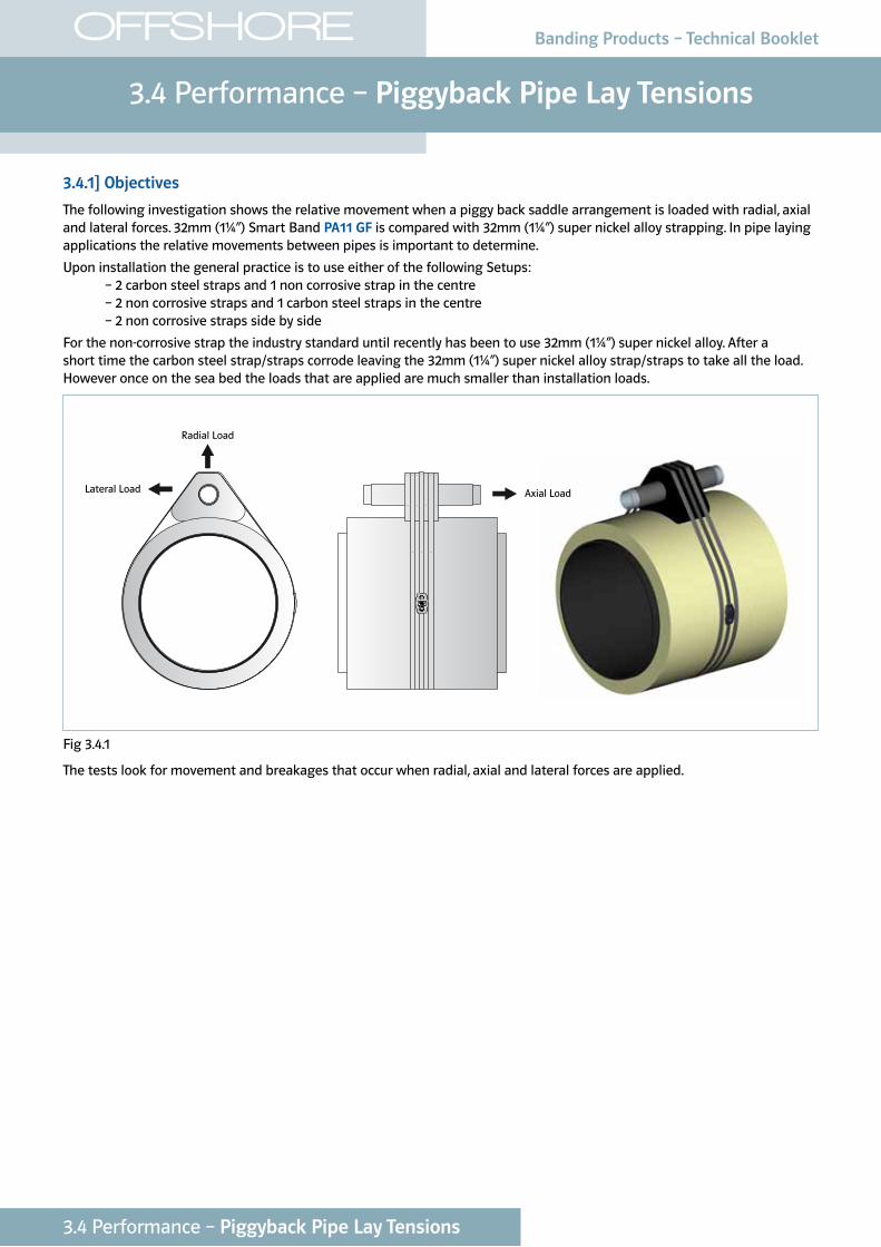
3.4.1] Objectives
The following investigation shows the relative movement when a piggy back saddle arrangement is loaded with radial, axial and lateral forces. 32mm (1¼”) Smart Band PA11 GF is compared with 32mm (1¼”) super nickel alloy strapping. In pipe laying applications the relative movements between pipes is important to determine.
Upon installation the general practice is to use either of the following Setups: – 2 carbon steel straps and 1 non corrosive strap in the centre – 2 non corrosive straps and 1 carbon steel straps in the centre – 2 non corrosive straps side by side
For the non-corrosive strap the industry standard until recently has been to use 32mm (1¼”) super nickel alloy. After a short time the carbon steel strap/straps corrode leaving the 32mm (1¼”) super nickel alloy strap/straps to take all the load. However once on the sea bed the loads that are applied are much smaller than installation loads.
Radial Load
Axial LoadLateral Load
Fig 3.4.1
The tests look for movement and breakages that occur when radial, axial and lateral forces are applied.
Banding Products – Technical Booklet
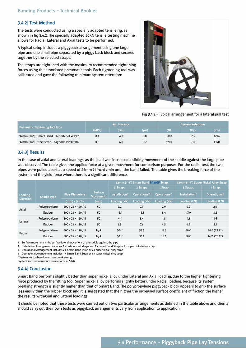
3.4.2] Test Method
The tests were conducted using a specially adapted tensile rig, as shown in fig 3.4.2. The specially adapted 50KN tensile testing machine allows for Radial, Lateral and Axial tests to be performed.
A typical setup includes a piggyback arrangement using one large pipe and one small pipe separated by a piggy back block and secured together by the selected straps.
The straps are tightened with the maximum recommended tightening forces using the associated pneumatic tools. Each tightening tool was calibrated and gave the following minimum system retention:
Pneumatic Tightening Tool TypeAir Pressure System Retention
(MPa) (Bar) (psi) (N) (Kg) (lbs)
32mm (1¼") Smart Band – Air ratchet W2301 0.4 4.0 58 8000 815 1794
32mm (1¼") Steel strap – Signode PRHR-114 0.6 6.0 87 6200 632 1390
3.4.3] Results
In the case of axial and lateral loadings, as the load was increased a sliding movement of the saddle against the large pipe was observed. The table gives the applied force at a given movement for comparison purposes. For the radial test, the two pipes were pulled apart at a speed of 25mm (1 inch) /min until the band failed. The table gives the breaking force of the system and the yield force where there is a significant difference.
32mm (1¼") Smart Band PA11GF Strap 32mm (1¼") Super Nickel Alloy Strap
3 Straps 2 Straps 1 Strap 3 Straps 1 Strap
Loading Direction
Saddle TypePipe Diameters
Surface Movement1 Installation2 Operational3 Operational4 Installation2 Operational4
(mm) / (inch) (mm) Loading (kN) Loading (kN) Loading (kN) Loading (kN) Loading (kN)
AxialPolypropylene 600 / 24 + 120 / 5 50 9.2 7.3 2.9 5.9 2.9
Rubber 600 / 24 + 120 / 5 50 15.4 13.5 8.4 17.0 8.2
LateralPolypropylene 600 / 24 + 120 / 5 50 4.1 3.4 1.8 4.1 1.6
Rubber 600 / 24 + 120 / 5 50 6.3 7.6 4.3 4.9 2.1
RadialPolypropylene 600 / 24 + 120 / 5 N/A 50+* 33.5 19.3 50+* 26.6 (22.1**)
Rubber 600 / 24 + 120 / 5 N/A 50+* 31.1 15.6 50+* 24/4 (20.1**)
1 Surface movement is the surface lateral movement of the saddle against the pipe 2 Installation Arrangement includes 2 x carbon steel straps and 1 x Smart Band Strap or 1 x super nickel alloy strap 3 Operational Arrangement includes 2 x Smart Band Strap or 2 x super nickel alloy strap 4 Operational Arrangement includes 1 x Smart Band Strap or 1 x super nickel alloy strap **System yield, where lower than break strength *System survived maximum tensile force of 50kN
3.4.4] Conclusion
Smart Band performs slightly better than super nickel alloy under Lateral and Axial loading, due to the higher tightening force produced by the fitting tool. Super nickel alloy performs slightly better under Radial loading, because its system breaking strength is slightly higher than that of Smart Band. The polypropylene piggyback block appears to grip the surface less easily than the rubber block and it is suggested that the higher the increased surface coefficient of friction the higher the results withAxial and Lateral loadings.
It should be noted that these tests were carried out on two particular arrangements as defined in the table above and clients should carry out their own tests as piggyback arrangements vary from application to application.
Fig 3.4.2 – Typical arrangement for a lateral pull test
3.4 Performance – Piggyback Pipe Lay Tensions
3.5 Performance – Temperature Resistance
OFFSHORE
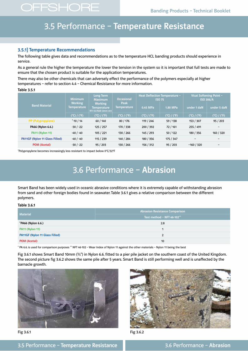
3.5.1] Temperature RecommendationsThe following table gives data and recommendations as to the temperature HCL banding products should experience in service.
As a general rule the higher the temperature the lower the tension in the system so it is important that full tests are made to ensure that the chosen product is suitable for the application temperatures.
There may also be other chemicals that can adversely effect the performance of the polymers especially at higher temperatures – refer to section 4.4 – Chemical Resistance for more information.
Table 3.5.1
Band Material
Minimum Working
Temperature
Long Term Maximum Working
Temperature RTI UL746B (3mm str)
Occasional Peak
Temperature
Heat Deflection Temperature – ISO 75
Vicat Softening Point – ISO 306/A
0.45 MPa 1.80 MPa under 1 daN under 5 daN
(°C) / (°F) (°C) / (°F) (°C) / (°F) (°C) / (°F) (°C) / (°F) (°C) / (°F) (°C) / (°F)
PP (Polypropylene) *-10 / 14 60 / 140 80 / 176 119 / 246 59 / 138 153 / 307 95 / 203
PA66 (Nylon 6.6.) -30 / -22 125 / 257 170 / 338 200 / 392 72 / 161 255 / 491 –
PA11 (Nylon 11) -40 / -40 105 / 221 130 / 266 145 / 293 50 / 122 180 / 356 160 / 320
PA11GF (Nylon 11 Glass Filled) -40 / -40 115 / 239 140 / 284 180 / 356 175 / 347 – –
POM (Acetal) -30 / -22 95 / 203 130 / 266 156 / 312 95 / 203 ~160 / 320 –
*Polypropylene becomes increasingly less resistant to impact below 0°C/32°F
Banding Products – Technical Booklet
Fig 3.6.1 Fig 3.6.2
3.6 Performance – Abrasion
Smart Band has been widely used in oceanic abrasive conditions where it is extremely capable of withstanding abrasion from sand and other foreign bodies found in seawater. Table 3.6.1 gives a relative comparison between the different polymers.
Table 3.6.1
MaterialAbrasion Resistance Comparison
Test method – NFT 46-102**
*PA66 (Nylon 6.6.) 2.8
PA11 (Nylon 11) 1
PA11GF (Nylon 11 Glass Filled) 2
POM (Acetal) 10
* PA 6.6. is used for comparison purposes ** NFT 46-102 – Wear Index of Nylon 11 against the other materials – Nylon 11 being the best
Fig 3.6.1 shows Smart Band 10mm (³⁄8”) in Nylon 6.6. fitted to a pier pile jacket on the southern coast of the United Kingdom. The second picture fig 3.6.2 shows the same pile after 5 years. Smart Band is still performing well and is unaffected by the barnacle growth.
3.6 Performance – Abrasion3.5 Performance – Temperature Resistance
4.1 Material – Material Data
OFFSHORE
4.1 Material – Material Data
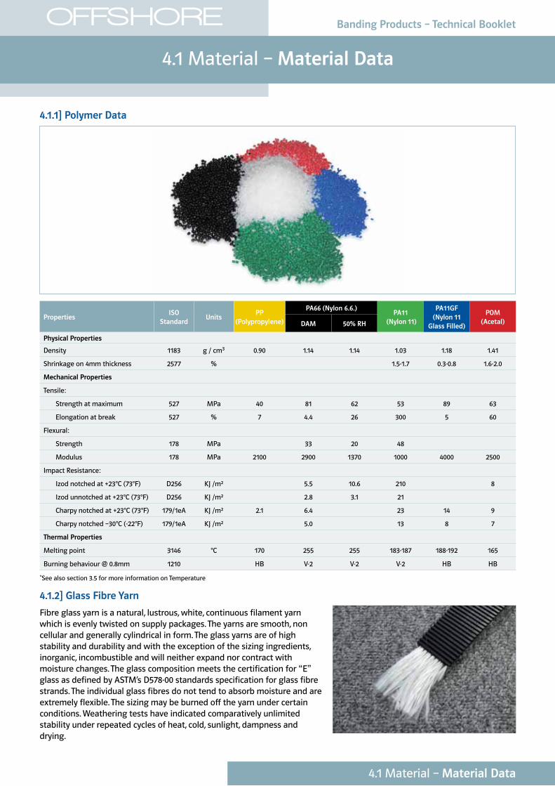
4.1.1] Polymer Data
PropertiesISO
StandardUnits
PP (Polypropylene)
PA66 (Nylon 6.6.)PA11
(Nylon 11)
PA11GF (Nylon 11
Glass Filled)
POM (Acetal)DAM 50% RH
Physical Properties
Density 1183 g / cm3 0.90 1.14 1.14 1.03 1.18 1.41
Shrinkage on 4mm thickness 2577 % 1.5-1.7 0.3-0.8 1.6-2.0
Mechanical Properties
Tensile:
Strength at maximum 527 MPa 40 81 62 53 89 63
Elongation at break 527 % 7 4.4 26 300 5 60
Flexural:
Strength 178 MPa 33 20 48
Modulus 178 MPa 2100 2900 1370 1000 4000 2500
Impact Resistance:
Izod notched at +23°C (73°F) D256 KJ /m² 5.5 10.6 210 8
Izod unnotched at +23°C (73°F) D256 KJ /m² 2.8 3.1 21
Charpy notched at +23°C (73°F) 179/1eA KJ /m² 2.1 6.4 23 14 9
Charpy notched –30°C (-22°F) 179/1eA KJ /m² 5.0 13 8 7
Thermal Properties
Melting point 3146 °C 170 255 255 183-187 188-192 165
Burning behaviour @ 0.8mm 1210 HB V-2 V-2 V-2 HB HB
*See also section 3.5 for more information on Temperature
4.1.2] Glass Fibre Yarn
Fibre glass yarn is a natural, lustrous, white, continuous filament yarn which is evenly twisted on supply packages. The yarns are smooth, non cellular and generally cylindrical in form. The glass yarns are of high stability and durability and with the exception of the sizing ingredients, inorganic, incombustible and will neither expand nor contract with moisture changes. The glass composition meets the certification for “E” glass as defined by ASTM’s D578-00 standards specification for glass fibre strands. The individual glass fibres do not tend to absorb moisture and are extremely flexible. The sizing may be burned off the yarn under certain conditions. Weathering tests have indicated comparatively unlimited stability under repeated cycles of heat, cold, sunlight, dampness and drying.
Banding Products – Technical Booklet
OFFSHORE Banding Products – Technical Booklet
4.2 Material – Moisturising Effects
4.2 Material – Moisturising Effects
Among all the performance polyamides, PA11 (Nylon 11) and PA11GF (Nylon 11 Glass Filled) have very low moisture pick-up. Other polyamides feature a more hydrophilic behaviour resulting from the polarity of the amide functions. Thanks to a low concentration of amide groups, PA11 (Nylon 11) and PA11GF (Nylon 11 Glass Filled) are very suitable for humid conditions including full immersion in water.
POM (Acetal) is virtually impervious to water and so exhibits negligible moisture pick-up.
Table 4.2.1
MaterialWater Absorption %
50% RH (23°C (73°F)) Saturation (23°C (73°F) in water)
PA66 (Nylon 6.6.) 2.9 8.5
PA11 (Nylon 11) 0.9 1.9
PA11GF (Nylon 11 Glass Filled) 0.6 1.5
POM (Acetal) <0.25 <0.35
Water is the critical medium for Polyamides (such as PA11). Please refer to Section 4.3, Material – Material Life in Offshore Environments; for more information.
Please refer to Section 3.1 Performance – Strength; for tests carried out following 8 months immersion of Smart Band in water.
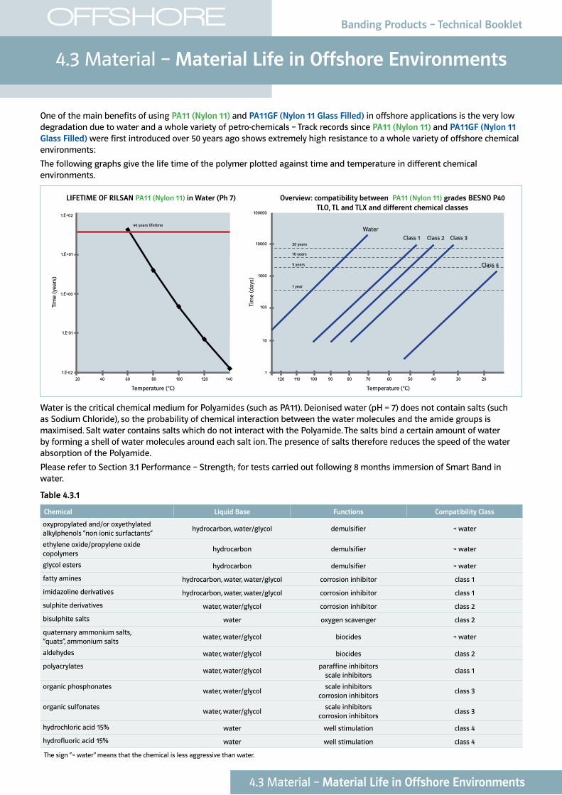
One of the main benefits of using PA11 (Nylon 11) and PA11GF (Nylon 11 Glass Filled) in offshore applications is the very low degradation due to water and a whole variety of petro-chemicals – Track records since PA11 (Nylon 11) and PA11GF (Nylon 11 Glass Filled) were first introduced over 50 years ago shows extremely high resistance to a whole variety of offshore chemical environments:
The following graphs give the life time of the polymer plotted against time and temperature in different chemical environments.
20 40 120 110 100 90 80 70 60 50 40 30 2060 80 100 120 1401.E-02 1
10
100
1000
10000
100000
1.E-01
1.E+00
1.E+01
1.E+02
Temperature (°C)
Tim
e (y
ears
)
Temperature (°C)
Tim
e (d
ays)
40 years lifetime
1 year
5 years
10 years
20 years
Water
Class 1 Class 2 Class 3
Class 4
Water is the critical chemical medium for Polyamides (such as PA11). Deionised water (pH = 7) does not contain salts (such as Sodium Chloride), so the probability of chemical interaction between the water molecules and the amide groups is maximised. Salt water contains salts which do not interact with the Polyamide. The salts bind a certain amount of water by forming a shell of water molecules around each salt ion. The presence of salts therefore reduces the speed of the water absorption of the Polyamide.
Please refer to Section 3.1 Performance – Strength; for tests carried out following 8 months immersion of Smart Band in water.
Table 4.3.1
Chemical Liquid Base Functions Compatibility Class
oxypropylated and/or oxyethylated alkylphenols “non ionic surfactants”
hydrocarbon, water/glycol demulsifier < water
ethylene oxide/propylene oxide copolymers
hydrocarbon demulsifier < water
glycol esters hydrocarbon demulsifier < water
fatty amines hydrocarbon, water, water/glycol corrosion inhibitor class 1
imidazoline derivatives hydrocarbon, water, water/glycol corrosion inhibitor class 1
sulphite derivatives water, water/glycol corrosion inhibitor class 2
bisulphite salts water oxygen scavenger class 2
quaternary ammonium salts, “quats”, ammonium salts
water, water/glycol biocides < water
aldehydes water, water/glycol biocides class 2
polyacrylateswater, water/glycol
paraffine inhibitors scale inhibitors
class 1
organic phosphonateswater, water/glycol
scale inhibitors corrosion inhibitors
class 3
organic sulfonateswater, water/glycol
scale inhibitors corrosion inhibitors
class 3
hydrochloric acid 15% water well stimulation class 4
hydrofluoric acid 15% water well stimulation class 4
The sign “< water” means that the chemical is less aggressive than water.
LIFETIME OF RILSAN PA11 (Nylon 11) in Water (Ph 7) Overview: compatibility between PA11 (Nylon 11) grades BESNO P40 TLO, TL and TLX and different chemical classes
OFFSHORE Banding Products – Technical Booklet
4.3 Material – Material Life in Offshore Environments
4.3 Material – Material Life in Offshore Environments
4.4 Material – Chemical Resistance
OFFSHORE Banding Products – Technical Booklet
Table 4.4.1
Chemical AgentConcen-tration†
(100%)
PP (Polypropylene) Performance Concen-tration†
(100%)
PA66 (Nylon 6.6.) Performance Concen-tration†
(100%)
PA11 (Nylon 11) Performance Concen-tration†
(100%)
POM (Acetal) Performance
20°C (68°F)
40°C (104°F)
60°C (140°F)
90°C (194°F)
unknown °C
23°C (73.4°F)
49°C (120.2°F)
82°C (179.6°F)
20°C (68°F)
60°C (140°F) Temp°C PA6.6††
Mineral AcidsBoric acid Sat. Sol. G G 7% 24 P GCarbonic acid Sat. Sol. G G 10% 24 G G
Chloroacetic acid Sol L P 10% 24 P PChlorosulphonic acid Tg-s P P 10% 24 P PChromic acid 40% L L 10% 24 P 10% P P P P 10% PHydrochloric acid 10%
30%
Gaseous
G
G
G
G
G
2.5%
5%
10%
23
77
25
G
P
P
1%
10%
G
G
L
L
P
P
P
P
20%
37%
100%
G
G
G
PNitric acid 10%
65%
100%
G
G
P
P
P
P
10% 23 P 10% P P P P 5-10%
50%
P
P
Perchloric acid 20% G 10% 24 P GPhosphoric acid 30%
90%
G
G
G
G
5%
50%
98 P 5%
50%
G L P P P
PSulphur dioxide Gaseous, Dry
Gaseous,
Wet
G
L
38 P L P P P G
Sulphuric acid 10%
50%
80%
98%
G
L
L
L
G
P
P
P
1%
3%
10%
30%
23
P
1%
10%
G
G
L
L
L
L
P
P
3%
30%
G
P
Sulphurous acid L P 10% 23 P GMineral SaltsAluminium hydroxide Sat. Sol. G G 10%
10%
23
52
L
P
10% G* G*
Alumina sulphate Sat. Sol. G G Sat. Sol.
10%
10%
23
52
L
P
Concentrat-
ed or boiled
solutions
G G G G p
Ammonium carbonate 100% G G 10% 23 L PAmmonium chloride 100% G G 10% 52 P GAmmonium hydroxide 10%
28%
100%
G
G
L
G
G
10% 23
70
G**
P**
G
Ammonium sulphate Sat. Sol.
100%
G
L
G Sat. Sol. Concentrat-
ed or boiled
solutions
G G L G
Antimony trichloride Sat. Sol. G G 10% 24 PBarium chloride Sat. Sol. G G Sat. Sol.
10%
24
P
Concentrat-
ed or boiled
solutions
G G G G G
Barium sulphate Sat. Sol. G G 10% 24 G GBarium Sulphide Sat. Sol. G G 10% 24 L GCalcium arsenate Sat. Sol. G G Concentrat-
ed or boiled
solutions
G G G
Calcium chloride Sat. Sol. G G Sat. Sol.
5%
60
P
Concentrat-
ed or boiled
solutions
G G G G P
Calcium hypochlorite Sat. Sol. G L Sat. Sol. 35 P PCalcium thiocynate 50% PCopper chloride Sat. Sol. G G 10% 24 P GCopper sulphate Sat. Sol. G G Sat. Sol. Concentrat-
ed or boiled
solutions
G G G G P
Copper sulphite Sat. Sol. G G 10% 24 PDi-ammonium phosphate Sat. Sol. G G Sat. Sol. Concentrat-
ed or boiled
solutions
G G L
Hydrogen sulphide Gaseous, Dry G G Sat. Sol. 23 P GMagnesium chloride Sat. Sol. G G 50% 50% G G G G GPotassium carbonate Sat. Sol. G G 50%
20%
98°C
G
G
Potassium chloride Sat. Sol. G G 90% 23 G GPotassium hydroxide Sat. Sol. G G 30% 98 L GPotassium nitrate Sat. Sol. G G Sat. Sol. Concentrat-
ed or boiled
solutions
G* L* P P G
4.4 Material – Chemical Resistance
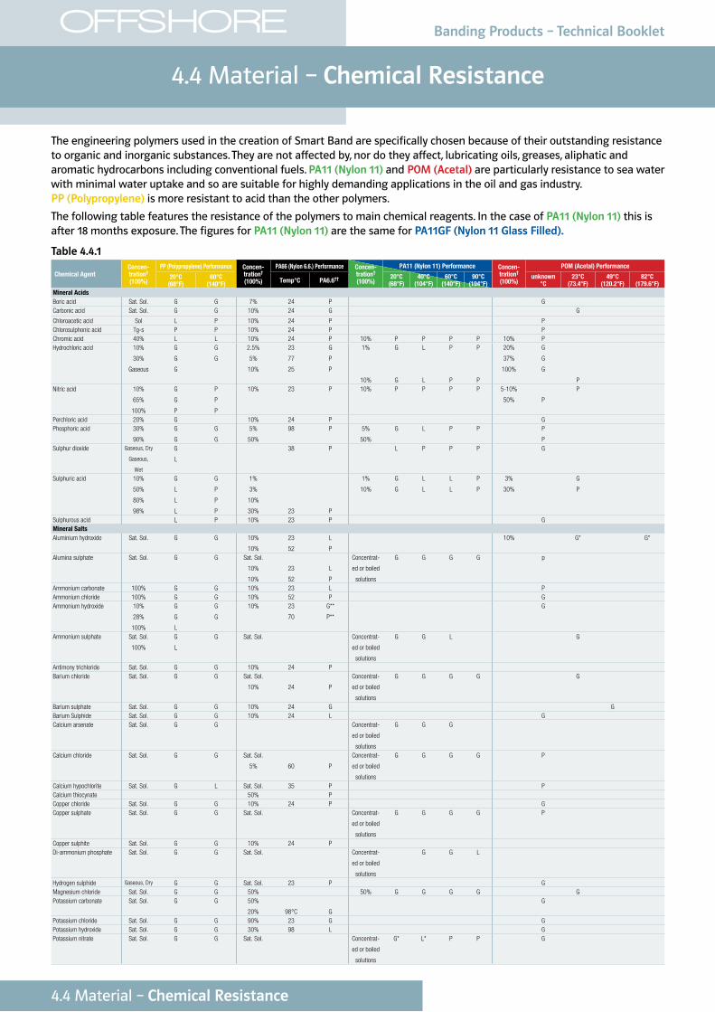
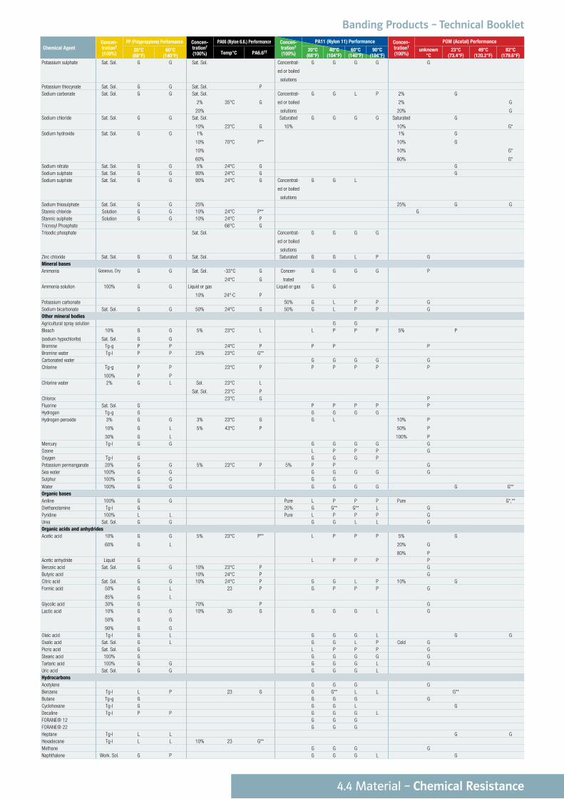
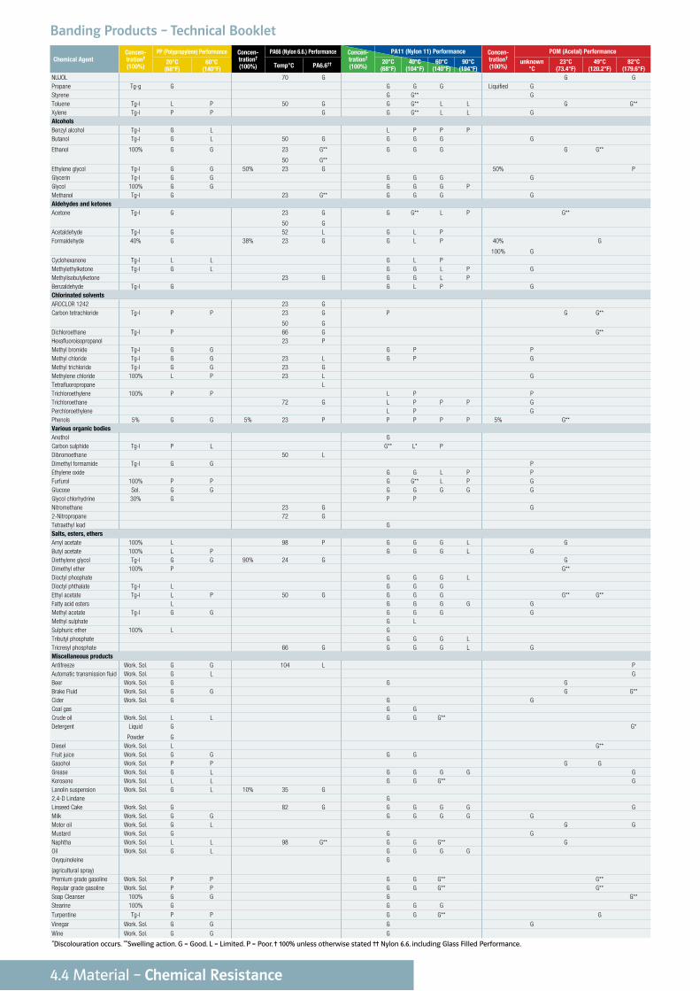
The engineering polymers used in the creation of Smart Band are specifically chosen because of their outstanding resistance to organic and inorganic substances. They are not affected by, nor do they affect, lubricating oils, greases, aliphatic and aromatic hydrocarbons including conventional fuels. PA11 (Nylon 11) and POM (Acetal) are particularly resistance to sea water with minimal water uptake and so are suitable for highly demanding applications in the oil and gas industry. PP (Polypropylene) is more resistant to acid than the other polymers.
The following table features the resistance of the polymers to main chemical reagents. In the case of PA11 (Nylon 11) this is after 18 months exposure. The figures for PA11 (Nylon 11) are the same for PA11GF (Nylon 11 Glass Filled).
4.4 Material – Chemical Resistance
Banding Products – Technical Booklet
Chemical AgentConcen-tration†
(100%)
PP (Polypropylene) Performance Concen-tration†
(100%)
PA66 (Nylon 6.6.) Performance Concen-tration†
(100%)
PA11 (Nylon 11) Performance Concen-tration†
(100%)
POM (Acetal) Performance
20°C (68°F)
40°C (104°F)
60°C (140°F)
90°C (194°F)
unknown °C
23°C (73.4°F)
49°C (120.2°F)
82°C (179.6°F)
20°C (68°F)
60°C (140°F) Temp°C PA6.6††
Potassium sulphate Sat. Sol. G G Sat. Sol. Concentrat-
ed or boiled
solutions
G G G G G
Potassium thiocynate Sat. Sol. G G Sat. Sol. PSodium carbonate Sat. Sol. G G Sat. Sol.
2%
20%
35°C
G
Concentrat-
ed or boiled
solutions
G G L P 2%
2%
20%
G
G
GSodium chloride Sat. Sol. G G Sat. Sol.
10%
23°C
G
Saturated
10%
G G G G Saturated
10%
G
G*Sodium hydroxide Sat. Sol. G G 1%
10%
10%
60%
70°C
P**
1%
10%
10%
60%
G
G
G*
G*Sodium nitrate Sat. Sol. G G 5% 24°C G GSodium sulphate Sat. Sol. G G 90% 24°C G GSodium sulphide Sat. Sol. G G 90% 24°C G Concentrat-
ed or boiled
solutions
G G L
Sodium thiosulphate Sat. Sol. G G 25% 25% G GStannic chloride Solution G G 10% 24°C P** GStannic sulphate Solution G G 10% 24°C PTricresyl Phosphate 66°C GTrisodic phosphate Sat. Sol. Concentrat-
ed or boiled
solutions
G G G G
Zinc chloride Sat. Sol. G G Sat. Sol. Saturated G G L P GMineral basesAmmonia Gaseous, Dry G G Sat. Sol. -33°C
24°C
G
G
Concen-
trated
G G G G P
Ammonia solution 100% G G Liquid or gas
10%
24°·C
P
Liquid or gas G G
Potassium carbonate 50% G L P P GSodium bicarbonate Sat. Sol. G G 50% 24°C G 50% G L P P GOther mineral bodiesAgricultural spray solution G GBleach
(sodium hypochlorite)
10%
Sat. Sol.
G
G
G
G
5% 23°C L L P P P 5% P
Bromine Tg-g P P 24°C P P P PBromine water Tg-l P P 25% 23°C G**Carbonated water G G G G GChlorine Tg-g
100%
P
P
P
P
23°C P P P P P P
Chlorine water 2% G L Sol.
Sat. Sol.
23°C
23°C
L
PChlorox 23°C G PFluorine Sat. Sol. G P P P P PHydrogen Tg-g G G G G GHydrogen peroxide 3%
10%
30%
G
G
G
G
L
L
3%
5%
23°C
43°C
G
P
G L 10%
50%
100%
P
P
PMercury Tg-l G G G G G G GOzone L P P P GOxygen Tg-l G G G G PPotassium permanganate 20% G G 5% 23°C P 5% P P GSea water 100% G G G G G G GSulphur 100% G G G G
Water 100% G G G G G G G G**Organic basesAniline 100% G G Pure L P P P Pure G*,**Diethanolamine Tg-l G 20% G G** G** L GPyridine 100% L L Pure L P P P GUrea Sat. Sol. G G G G L L GOrganic acids and anhydridesAcetic acid 10%
60%
G
G
G
L
5% 23°C P** L P P P 5%
20%
80%
G
P
G
Acetic anhydride Liquid G L P P P PBenzoic acid Sat. Sol. G G 10% 23°C P GButyric acid 10% 24°C P GCitric acid Sat. Sol. G G 10% 24°C P G G L P 10% GFormic acid 50%
85%
G
G
L
L
23 P G P P P G
Glycolic acid 30% G 70% P GLactic acid 10%
50%
90%
G
G
G
G
G
G
10% 35 G G G G L G
Oleic acid Tg-l G L G G G L G GOxalic acid Sat. Sol. G L G G L P Cold GPicric acid Sat. Sol. G L P P P GStearic acid 100% G G G G G GTartaric acid 100% G G G G G L GUric acid Sat. Sol. G G G G G LHydrocarbonsAcetylene G G G GBenzene Tg-l L P 23 G G G** L L G**Butane Tg-g G G G G GCyclohexane Tg-l G G G L GDecaline Tg-l P P G G G LFORANE® 12 G G GFORANE® 22 G G GHeptane Tg-l L L G GHexadecane Tg-l L L 10% 23 G**Methane G G G GNaphthalene Work. Sol. G P G G G L G
OFFSHORE
4.4 Material – Chemical Resistance
Banding Products – Technical Booklet
Chemical AgentConcen-tration†
(100%)
PP (Polypropylene) Performance Concen-tration†
(100%)
PA66 (Nylon 6.6.) Performance Concen-tration†
(100%)
PA11 (Nylon 11) Performance Concen-tration†
(100%)
POM (Acetal) Performance
20°C (68°F)
40°C (104°F)
60°C (140°F)
90°C (194°F)
unknown °C
23°C (73.4°F)
49°C (120.2°F)
82°C (179.6°F)
20°C (68°F)
60°C (140°F) Temp°C PA6.6††
NUJOL 70 G G GPropane Tg-g G G G G Liquified GStyrene G G** GToluene Tg-l L P 50 G G G** L L G G**Xylene Tg-l P P G G G** L L GAlcoholsBenzyl alcohol Tg-l G L L P P PButanol Tg-l G L 50 G G G G G
Ethanol 100% G G 23
50
G**
G**
G G G G G**
Ethylene glycol Tg-l G G 50% 23 G 50% PGlycerin Tg-l G G G G G GGlycol 100% G G G G G PMethanol Tg-l G 23 G** G G G GAldehydes and ketonesAcetone Tg-l G 23
50
G
G
G G** L P G**
Acetaldehyde Tg-l G 52 L G L PFormaldehyde 40% G 38% 23 G G L P 40%
100%
G
G
Cyclohexanone Tg-l L L G L PMethylethylketone Tg-l G L G G L P GMethylisobutylketone 23 G G G L PBenzaldehyde Tg-l G G L P GChlorinated solventsAROCLOR 1242 23 GCarbon tetrachloride Tg-l P P 23
50
G
G
P G G**
Dichloroethane Tg-l P 66 G G**Hexafluoroisopropanol 23 PMethyl bromide Tg-l G G G P PMethyl chloride Tg-l G G 23 L G P GMethyl trichloride Tg-l G G 23 GMethylene chloride 100% L P 23 L GTetrafluoropropane LTrichloroethylene 100% P P L P PTrichloroethane 72 G L P P P GPerchloroethylene L P GPhenols 5% G G 5% 23 P P P P P 5% G**Various organic bodiesAnethol GCarbon sulphide Tg-l P L G** L* PDibromoethane 50 LDimethyl formamide Tg-l G G PEthylene oxide G G L P PFurfurol 100% P P G G** L P GGlucose Sol. G G G G G G GGlycol chlorhydrine 30% G P PNitromethane 23 G G2-Nitropropane 72 GTetraethyl lead GSalts, esters, ethersAmyl acetate 100% L 98 P G G G L GButyl acetate 100% L P G G G L GDiethylene glycol Tg-l G G 90% 24 G GDimethyl ether 100% P G**Dioctyl phosphate G G G LDioctyl phthalate Tg-l L G G GEthyl acetate Tg-l L P 50 G G G G G** G**Fatty acid esters L G G G G GMethyl acetate Tg-l G G G G G GMethyl sulphate G LSulphuric ether 100% L GTributyl phosphate G G G LTricresyl phosphate 66 G G G G L GMiscellaneous productsAntifreeze Work. Sol. G G 104 L PAutomatic transmission fluid Work. Sol. G L GBeer Work. Sol. G G GBrake Fluid Work. Sol. G G G G**Cider Work. Sol. G G GCoal gas G GCrude oil Work. Sol. L L G G G**Detergent Liquid
Powder
G
G
G*
Diesel Work. Sol. L G**Fruit juice Work. Sol. G G G GGasohol Work. Sol. P P G GGrease Work. Sol. G L G G G G GKerosene Work. Sol. L L G G G** GLanolin suspension Work. Sol. G L 10% 35 G2,4-D Lindane GLinseed Cake Work. Sol. G 82 G G G G G GMilk Work. Sol. G G G G G G GMotor oil Work. Sol. G L G GMustard Work. Sol. G G GNaphtha Work. Sol. L L 98 G** G G G** GOil Work. Sol. G L G G G GOxyquinoleine
(agricultural spray)
G
Premium grade gasoline Work. Sol. P P G G G** G**Regular grade gasoline Work. Sol. P P G G G** G**Soap Cleanser 100% G G G G**Stearine 100% G G G G
Turpentine Tg-l P P G G G** G
Vinegar Work. Sol. G G G G
Wine Work. Sol. G G G
*Discolouration occurs. **Swelling action. G = Good. L = Limited. P = Poor. † 100% unless otherwise stated †† Nylon 6.6. including Glass Filled Performance.
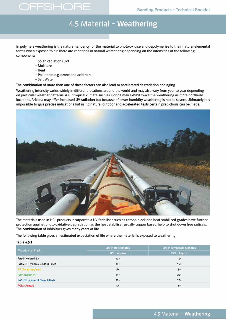
In polymers weathering is the natural tendency for the material to photo-oxidise and depolymerise to their natural elemental forms when exposed to air. There are variations in natural weathering depending on the intensities of the following components:
– Solar Radiation (UV) – Moisture – Heat – Pollutants e.g. ozone and acid rain – Salt Water
The combination of more than one of these factors can also lead to accelerated degradation and aging.
Weathering intensity varies widely in different locations around the world and may also vary from year to year depending on particular weather patterns. A subtropical climate such as Florida may exhibit twice the weathering as more northerly locations. Arizona may offer increased UV radiation but because of lower humidity weathering is not as severe. Ultimately it is impossible to give precise indications but using natural outdoor and accelerated tests certain predictions can be made.
The materials used in HCL products incorporate a UV Stabiliser such as carbon black and heat stabilised grades have further protection against photo-oxidative degradation as the heat stabiliser, usually copper based, help to shut down free radicals. The combination of inhibitors gives many years of life.
The following table gives an estimated expectation of life where the material is exposed to weathering:
Table 4.5.1
Materials all blackLife in Hot climates Life in Temperate Climates
YRS – Approx YRS – Approx
PA66 (Nylon 6.6.) 10+ 15+
PA66 GF (Nylon 6.6. Glass Filled) 10+ 15+
PP (Polypropylene) 5+ 8+
PA11 (Nylon 11) 15+ 20+
PA11GF (Nylon 11 Glass Filled) 15+ 20+
POM (Acetal) 5+ 8+
4.5 Material – Weathering
Banding Products – Technical Booklet
4.5 Material – Weathering
OFFSHORE
4.5 Material – Weathering
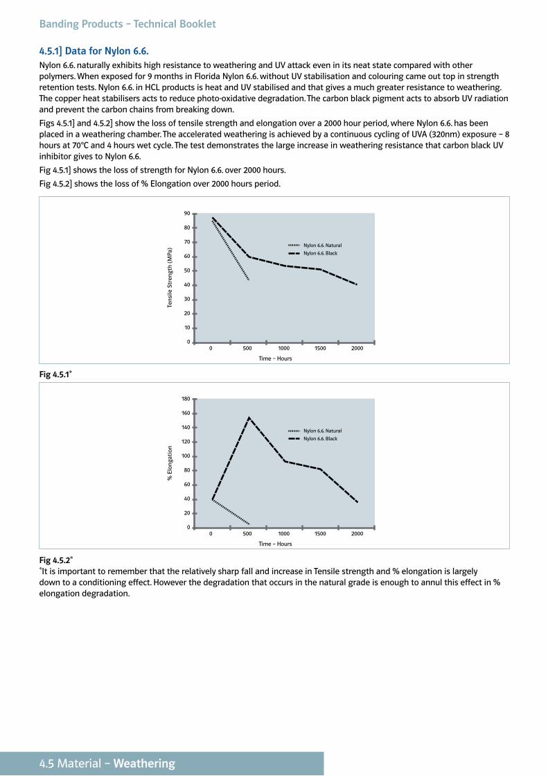
4.5.1] Data for Nylon 6.6.Nylon 6.6. naturally exhibits high resistance to weathering and UV attack even in its neat state compared with other polymers. When exposed for 9 months in Florida Nylon 6.6. without UV stabilisation and colouring came out top in strength retention tests. Nylon 6.6. in HCL products is heat and UV stabilised and that gives a much greater resistance to weathering. The copper heat stabilisers acts to reduce photo-oxidative degradation. The carbon black pigment acts to absorb UV radiation and prevent the carbon chains from breaking down.
Figs 4.5.1] and 4.5.2] show the loss of tensile strength and elongation over a 2000 hour period, where Nylon 6.6. has been placed in a weathering chamber. The accelerated weathering is achieved by a continuous cycling of UVA (320nm) exposure – 8 hours at 70°C and 4 hours wet cycle. The test demonstrates the large increase in weathering resistance that carbon black UV inhibitor gives to Nylon 6.6.
Fig 4.5.1] shows the loss of strength for Nylon 6.6. over 2000 hours.
Fig 4.5.2] shows the loss of % Elongation over 2000 hours period.
0 500 1000 1500 20000
50
40
30
20
10
60
70
80
90
Time – Hours
Ten
sile
Str
engt
h (
MP
a)
Nylon 6.6. Natural
Nylon 6.6. Black
Fig 4.5.1*
0 500 1000 1500 20000
100
80
60
40
20
120
140
160
180
Time – Hours
% E
lon
gati
on
Nylon 6.6. Natural
Nylon 6.6. Black
Fig 4.5.2**It is important to remember that the relatively sharp fall and increase in Tensile strength and % elongation is largely down to a conditioning effect. However the degradation that occurs in the natural grade is enough to annul this effect in % elongation degradation.
Banding Products – Technical Booklet
4.5 Material – Weathering
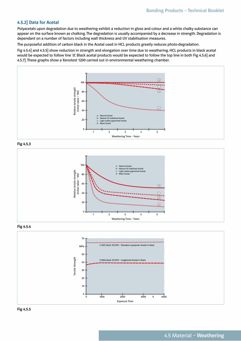
4.5.2] Data for AcetalPolyacetals upon degradation due to weathering exhibit a reduction in gloss and colour and a white chalky substance can appear on the surface known as chalking. The degradation is usually accompanied by a decrease in strength. Degradation is dependant on a number of factors including wall thickness and UV stabilisation measures.
The purposeful addition of carbon black in the Acetal used in HCL products greatly reduces photo-degradation.
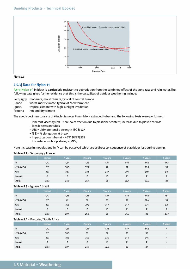
Fig 4.5.4] and 4.5.5] show reduction in strength and elongation over time due to weathering. HCL products in black acetal would be expected to follow line ‘d’. Black acetal products would be expected to follow the top line in both Fig 4.5.6] and 4.5.7]. These graphs show a Xenotest 1200 carried out in environmental weathering chamber.
1 2 3 4 50
40
20
60
80
100
Weathering Time – Years
Rel
ativ
e te
nsi
le s
tren
gth
(in
itia
l val
ue =
100
)
a – Natural Acetalb – Natural UV stabilised Acetalc – Light stable pigmented Acetald – Black Acetal
a
b
c
d
Fig 4.5.3
1 2 3 4 50
40
20
60
80
100
Weathering Time – Years
Rel
ativ
e te
nsi
le s
tren
gth
(in
itia
l val
ue =
100
)
a – Natural Acetalb – Natural UV stabilised Acetalc – Light stable pigmented Acetald – Black Acetal
a
b
c
d
Fig 4.5.4
0 1000 2000 3000 h 40000
30
20
10
40
50
70
MPa
Exposure Time
Ten
sile
Str
engt
h
C 9021 black 10/1570 – Standard copolymer Acetal in black
S 9064 black 10/1570 – toughened Acetal in black
Fig 4.5.5
Banding Products – Technical Booklet
0 1000 2000 3000 h 40000
30
20
10
40
%
50
Exposure Time
Elon
gati
on a
t b
reak
C 9021 black 10/1570 – Standard copolymer Acetal in black
S 9064 black 10/1570 – toughened Acetal in black
Fig 4.5.6
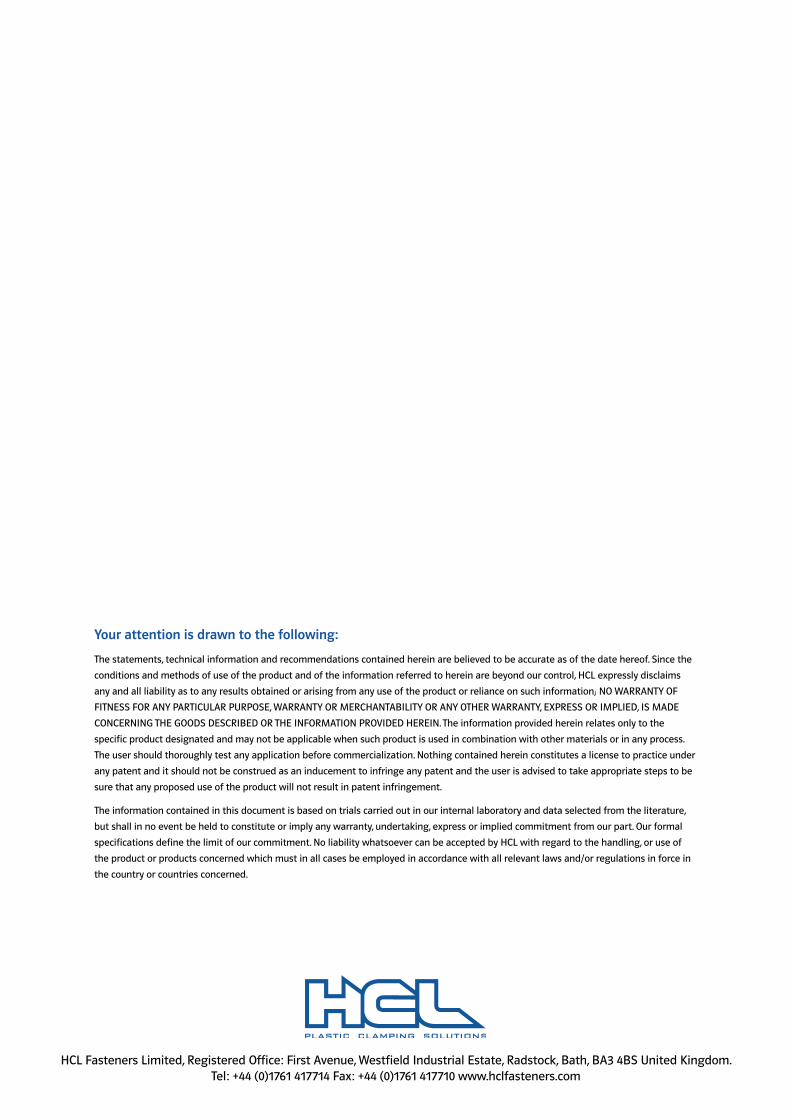
4.5.3] Data for Nylon 11 PA11 (Nylon 11) in black is particularly resistant to degradation from the combined effect of the sun’s rays and rain water. The following data gives further evidence that this is the case. Sites of outdoor weathering include:
Serquigny moderate, moist climate, typical of central Europe Bando warm, moist climate, typical of Mediterranean Iguazu tropical climate with high sunlight irradiation Pretoria hot and dry climate
The aged specimen consists of 6 inch diameter 8 mm black extruded tubes and the following tests were performed:
– Inherent viscosity (IV) – here no correction due to plasticizer content, increase due to plasticizer loss – Tensile tests on tubes – UTS = ultimate tensile strength ISO R 527 – % E = % elongation at break – Impact test on tubes at – 40°C, DIN 73378 – Instantaneous hoop stress, s (MPa)
Note Increase in modulus and in IV can be observed which are a direct consequence of plasticizer loss during ageing.
Table 4.5.2 – Serquigny / France
control 1 year 2 years 3 years 4 years 5 years 6 years
IV 1,42 1,54 1,55 1,64 1,66 1,62 1,63
UTS (MPa) 37 38,5 37,2 42 37 36,5 35
% E 357 329 338 347 291 309 316
Impact P P P P P P P
(MPa) 24,3 24,9 25,1 26 30,7 29,5 21
Table 4.5.3 – Iguazu / Brazil
control 1 year 2 years 3 years 4 years 5 years 6 years
IV 1,42 1,63 1,65 1,66 1,72 1,62 1,57
UTS (MPa) 37 42 38 38 39 37,4 39
% E 357 358 295 317 347 374 370
Impact P P P P P P P
(MPa) 24,3 29,4 25,6 26 31,5 33 29,7
Table 4.5.4 – Pretoria / South Africa
control 1 year 2 years 3 years 4 years 5 years 6 years
IV 1,42 1,56 1,66 1,83 1,67 1,62 –
UTS (MPa) 37 38,5 39 37 35 36 –
% E 357 343 365 335 344 346 –
Impact P P P P P P –
(MPa) 24,3 27,4 23,5 32,6 32 27 –
4.5 Material – Weathering
Banding Products – Technical Booklet
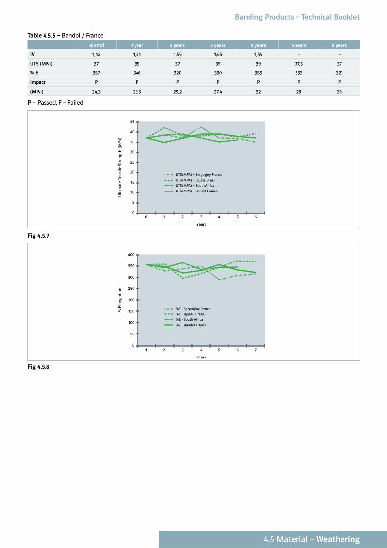
Table 4.5.5 – Bandol / France
control 1 year 2 years 3 years 4 years 5 years 6 years
IV 1,42 1,64 1,55 1,65 1,59 – –
UTS (MPa) 37 35 37 39 39 37,5 37
% E 357 346 320 330 355 333 321
Impact P P P P P P P
(MPa) 24,3 29,5 29,2 27,4 32 29 30
P = Passed, F = Failed
10 2 3 4 650
25
20
15
10
5
30
35
40
45
Years
Ult
imat
e Te
nsi
le S
tren
gth
(M
Pa)
UTS (MPA) – Serguigny France
UTS (MPA) – Iguazu Brazil
UTS (MPA) – South Africa
UTS (MPA) – Bandol France
Fig 4.5.7
21 3 4 5 760
200
150
100
50
250
300
350
400
Years
% E
lon
gati
on
%E – Serguigny France
%E – Iguazu Brazil
%E – South Africa
%E – Bandol France
Fig 4.5.8
Banding Products – Technical Booklet
4.5 Material – Weathering
Your attention is drawn to the following:
The statements, technical information and recommendations contained herein are believed to be accurate as of the date hereof. Since the
conditions and methods of use of the product and of the information referred to herein are beyond our control, HCL expressly disclaims
any and all liability as to any results obtained or arising from any use of the product or reliance on such information; NO WARRANTY OF
FITNESS FOR ANY PARTICULAR PURPOSE, WARRANTY OR MERCHANTABILITY OR ANY OTHER WARRANTY, EXPRESS OR IMPLIED, IS MADE
CONCERNING THE GOODS DESCRIBED OR THE INFORMATION PROVIDED HEREIN. The information provided herein relates only to the
specific product designated and may not be applicable when such product is used in combination with other materials or in any process.
The user should thoroughly test any application before commercialization. Nothing contained herein constitutes a license to practice under
any patent and it should not be construed as an inducement to infringe any patent and the user is advised to take appropriate steps to be
sure that any proposed use of the product will not result in patent infringement.
The information contained in this document is based on trials carried out in our internal laboratory and data selected from the literature,
but shall in no event be held to constitute or imply any warranty, undertaking, express or implied commitment from our part. Our formal
specifications define the limit of our commitment. No liability whatsoever can be accepted by HCL with regard to the handling, or use of
the product or products concerned which must in all cases be employed in accordance with all relevant laws and/or regulations in force in
the country or countries concerned.
HCL Fasteners Limited, Registered Office: First Avenue, Westfield Industrial Estate, Radstock, Bath, BA3 4BS United Kingdom.Tel: +44 (0)1761 417714 Fax: +44 (0)1761 417710 www.hclfasteners.com