Embed Size (px)
Citation preview
1 of 84
offshorecatalogue
Productinformation
OffshoreCablesBasicProgram
2 of 84
offshorecatalogue
Dear Customer,
At Draka Norsk Kabel, we take pleasure inpresenting this handbook, which coversalmost the total range of Your offshore(topside) cable needs.
The range comprises cables from 60V to20kV in applications like communication,data, instrumentation, power and control.
The products are subject to continuousresearch and improvement.The Quality Assurance system is certifiedby DnV, Det norske Veritas, to be inaccordance with ISO 9001 and 14001.
The Flex-Flame serie is today a multipurpose,”All in one”, offshore cable with dual compoundsheathing making the product resistant to oil,MUD and fire. It is, of course, halogenfree dueto environmental care.
Cables from Draka Norsk Kabel are distributedworldwide through our well established network.
We aim to provide solutions to suit your specialrequirements and trust you will find this handbookto be a useful tool in specifying your currentand future projects.
Yours Sincerely,
Draka Norsk Kabel AS
3 of 84
offshorecatalogue
Product INDEXHalogen-free, mud resistant instrumentation cable RFOU(i) 250V, S1/S5........................... 4
Halogen-free, mud resistant instrumentation cable RFOU(c) 250V, S2/S6 .......................... 7
Halogen-free, mud resistant, fire resistant instrumentation cable BFOU(i) 250V, S3/S7 . 10
Halogen-free, mud resistant, fire resistant instrumentation cable BFOU(c) 250V, S4/S8 . 13
Halogen-free Instrumentation cable OFFSHORE IYXI(c) 60V, S9 ..................................... 16
Halogen-free instrumentation cable OFFSHORE IYOI(c) 60V, S10................................... 19
Halogen-free instrumentation cable RU(i) 250V .................................................................... 22
Halogen-free instrumentation cable RU(c) 250V ................................................................... 25
Halogen-free fire resistant instrumentation cable BU(i) 250V.............................................. 28
Halogen-free fire resistant instrumentation cable BU(c) 250V............................................. 31
Halogen-free, mud resistant power cable RFOU 0,6/1kV, P1/P8......................................... 34
Halogen-free, mud resistant HV power cable RFOU 6/10(12)kV, P3/P10............................ 37
Halogen-free, mud resistant HV power cable RFOU 12/20(24)kV ........................................ 39
Halogen-free, mud resistant, fire resistant power cable BFOU 0.6/1kV, P5/P12 ............... 41
Halogen-free, mud resistant, fire resistant HV power cable BFOU 6/10(12)kV, P7/P14 .... 44
Insulated conductor UX 1000V, P15 ...................................................................................... 46
Halogen-free Unarmoured Power cable, RU 0,6/1kV ............................................................ 48
Halogen-free, fire resistant Unarmoured Power cable, BU 0,6/1kV ..................................... 51
High temperature, oil resistant insulated conductor Xline 125 SW..................................... 54
Halogen-free and fire resistant optical fibre cable QFCI ...................................................... 57
Approvals ................................................................................................................................. 59
Standards and tests:................................................................................................................ 60
Definition of terms ................................................................................................................... 61
Installation recommendations. ............................................................................................... 62
Electrical data........................................................................................................................... 67
Core colours for cables according to IEC.............................................................................. 76
Material properties................................................................................................................... 78
Physical and chemical properties of Draka Norsk Kabel's sheathing compounds .......... 79
Fire, flame, smoke and corrosion test methods.................................................................... 80
Drum capacity in meters ......................................................................................................... 82
Code designations for cables ................................................................................................. 84
4 of 84
offshorecatalogue
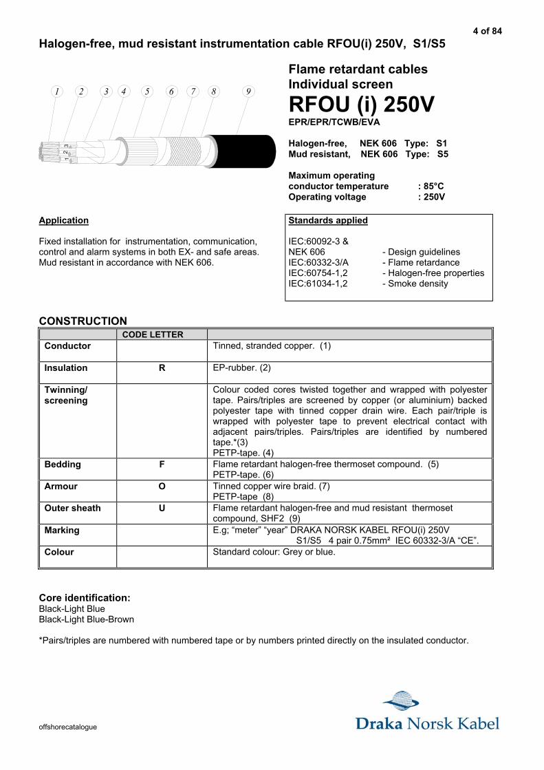
Halogen-free, mud resistant instrumentation cable RFOU(i) 250V, S1/S5
51 2 3 876
11
31
2
94
Flame retardant cablesIndividual screen
RFOU (i) 250VEPR/EPR/TCWB/EVA
Halogen-free, NEK 606 Type: S1Mud resistant, NEK 606 Type: S5
Maximum operatingconductor temperature : 85°COperating voltage : 250V
Application
Fixed installation for instrumentation, communication,control and alarm systems in both EX- and safe areas.Mud resistant in accordance with NEK 606.
Standards applied
IEC:60092-3 &NEK 606 - Design guidelinesIEC:60332-3/A - Flame retardanceIEC:60754-1,2 - Halogen-free propertiesIEC:61034-1,2 - Smoke density
CONSTRUCTIONCODE LETTER
Conductor Tinned, stranded copper. (1)
Insulation R EP-rubber. (2)
Twinning/screening
Colour coded cores twisted together and wrapped with polyestertape. Pairs/triples are screened by copper (or aluminium) backedpolyester tape with tinned copper drain wire. Each pair/triple iswrapped with polyester tape to prevent electrical contact withadjacent pairs/triples. Pairs/triples are identified by numberedtape.*(3)PETP-tape. (4)
Bedding F Flame retardant halogen-free thermoset compound. (5)PETP-tape. (6)
Armour O Tinned copper wire braid. (7)PETP-tape (8)
Outer sheath U Flame retardant halogen-free and mud resistant thermosetcompound, SHF2 (9)
Marking E.g; “meter” “year” DRAKA NORSK KABEL RFOU(i) 250V S1/S5 4 pair 0.75mm² IEC 60332-3/A “CE”.
Colour Standard colour: Grey or blue.
Core identification:Black-Light BlueBlack-Light Blue-Brown
*Pairs/triples are numbered with numbered tape or by numbers printed directly on the insulated conductor.
5 of 84
offshorecatalogue
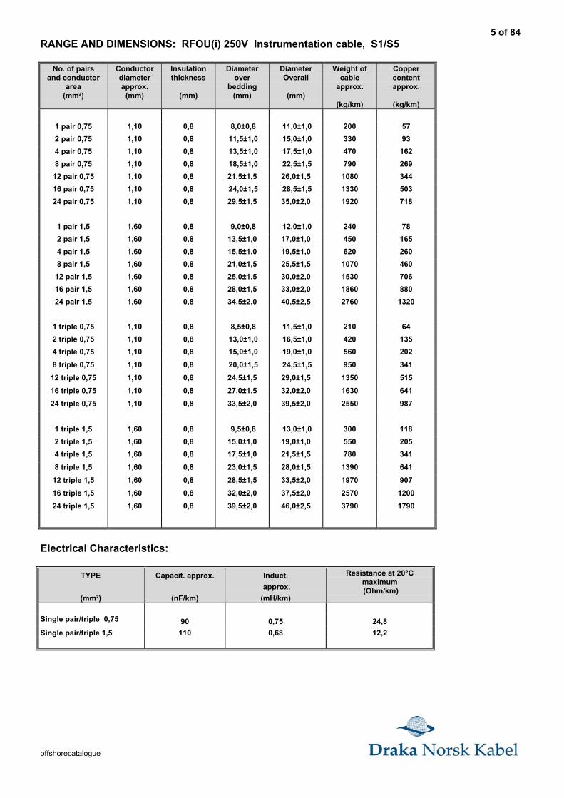
RANGE AND DIMENSIONS: RFOU(i) 250V Instrumentation cable, S1/S5
No. of pairsand conductor
area(mm²)
Conductordiameterapprox.
(mm)
Insulationthickness
(mm)
Diameterover
bedding(mm)
DiameterOverall
(mm)
Weight ofcable
approx.
(kg/km)
Coppercontentapprox.
(kg/km)
1 pair 0,75 1,10 0,8 8,0±0,8 11,0±1,0 200 57
2 pair 0,75 1,10 0,8 11,5±1,0 15,0±1,0 330 93
4 pair 0,75 1,10 0,8 13,5±1,0 17,5±1,0 470 162
8 pair 0,75 1,10 0,8 18,5±1,0 22,5±1,5 790 269
12 pair 0,75 1,10 0,8 21,5±1,5 26,0±1,5 1080 344
16 pair 0,75 1,10 0,8 24,0±1,5 28,5±1,5 1330 503
24 pair 0,75 1,10 0,8 29,5±1,5 35,0±2,0 1920 718
1 pair 1,5 1,60 0,8 9,0±0,8 12,0±1,0 240 78
2 pair 1,5 1,60 0,8 13,5±1,0 17,0±1,0 450 165
4 pair 1,5 1,60 0,8 15,5±1,0 19,5±1,0 620 260
8 pair 1,5 1,60 0,8 21,0±1,5 25,5±1,5 1070 460
12 pair 1,5 1,60 0,8 25,0±1,5 30,0±2,0 1530 706
16 pair 1,5 1,60 0,8 28,0±1,5 33,0±2,0 1860 880
24 pair 1,5 1,60 0,8 34,5±2,0 40,5±2,5 2760 1320
1 triple 0,75 1,10 0,8 8,5±0,8 11,5±1,0 210 64
2 triple 0,75 1,10 0,8 13,0±1,0 16,5±1,0 420 135
4 triple 0,75 1,10 0,8 15,0±1,0 19,0±1,0 560 202
8 triple 0,75 1,10 0,8 20,0±1,5 24,5±1,5 950 341
12 triple 0,75 1,10 0,8 24,5±1,5 29,0±1,5 1350 515
16 triple 0,75 1,10 0,8 27,0±1,5 32,0±2,0 1630 641
24 triple 0,75 1,10 0,8 33,5±2,0 39,5±2,0 2550 987
1 triple 1,5 1,60 0,8 9,5±0,8 13,0±1,0 300 118
2 triple 1,5 1,60 0,8 15,0±1,0 19,0±1,0 550 205
4 triple 1,5 1,60 0,8 17,5±1,0 21,5±1,5 780 341
8 triple 1,5 1,60 0,8 23,0±1,5 28,0±1,5 1390 641
12 triple 1,5 1,60 0,8 28,5±1,5 33,5±2,0 1970 907
16 triple 1,5 1,60 0,8 32,0±2,0 37,5±2,0 2570 1200
24 triple 1,5 1,60 0,8 39,5±2,0 46,0±2,5 3790 1790
Electrical Characteristics:
TYPE
(mm²)
Capacit. approx.
(nF/km)
Induct.
approx.
(mH/km)
Resistance at 20°Cmaximum (Ohm/km)
Single pair/triple 0,75 90 0,75 24,8
Single pair/triple 1,5 110 0,68 12,2
6 of 84
offshorecatalogue
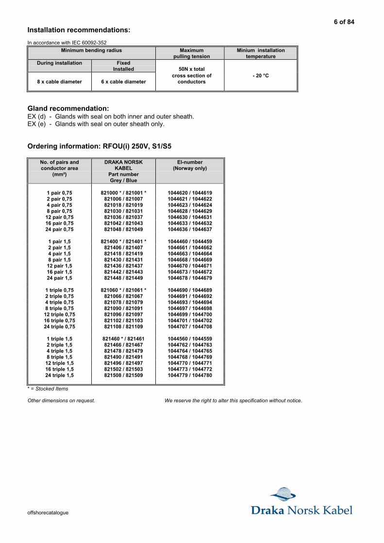
Installation recommendations:
In accordance with IEC 60092-352
Minimum bending radius Maximumpulling tension
Minium installationtemperature
During installation FixedInstalled 50N x total
8 x cable diameter 6 x cable diametercross section of
conductors- 20 °C
Gland recommendation:EX (d) - Glands with seal on both inner and outer sheath.EX (e) - Glands with seal on outer sheath only.
Ordering information: RFOU(i) 250V, S1/S5
No. of pairs andconductor area
(mm²)
DRAKA NORSKKABEL
Part numberGrey / Blue
El-number(Norway only)
1 pair 0,75 821000 * / 821001 * 1044620 / 10446192 pair 0,75 821006 / 821007 1044621 / 10446224 pair 0,75 821018 / 821019 1044623 / 10446248 pair 0,75 821030 / 821031 1044628 / 1044629
12 pair 0,75 821036 / 821037 1044630 / 104463116 pair 0,75 821042 / 821043 1044633 / 104463224 pair 0,75 821048 / 821049 1044636 / 1044637
1 pair 1,5 821400 * / 821401 * 1044460 / 10444592 pair 1,5 821406 / 821407 1044661 / 10446624 pair 1,5 821418 / 821419 1044663 / 10446648 pair 1,5 821430 / 821431 1044668 / 1044669
12 pair 1,5 821436 / 821437 1044670 / 104467116 pair 1,5 821442 / 821443 1044673 / 104467224 pair 1,5 821448 / 821449 1044678 / 1044679
1 triple 0,75 821060 * / 821061 * 1044690 / 10446892 triple 0,75 821066 / 821067 1044691 / 10446924 triple 0,75 821078 / 821079 1044693 / 10446948 triple 0,75 821090 / 821091 1044697 / 1044698
12 triple 0,75 821096 / 821097 1044699 / 104470016 triple 0,75 821102 / 821103 1044701 / 104470224 triple 0,75 821108 / 821109 1044707 / 1044708
1 triple 1,5 821460 * / 821461 1044560 / 10445592 triple 1,5 821466 / 821467 1044762 / 10447634 triple 1,5 821478 / 821479 1044764 / 10447658 triple 1,5 821490 / 821491 1044768 / 1044769
12 triple 1,5 821496 / 821497 1044770 / 104477116 triple 1,5 821502 / 821503 1044773 / 104477224 triple 1,5 821508 / 821509 1044779 / 1044780
* = Stocked Items
Other dimensions on request. We reserve the right to alter this specification without notice.
7 of 84
offshorecatalogue
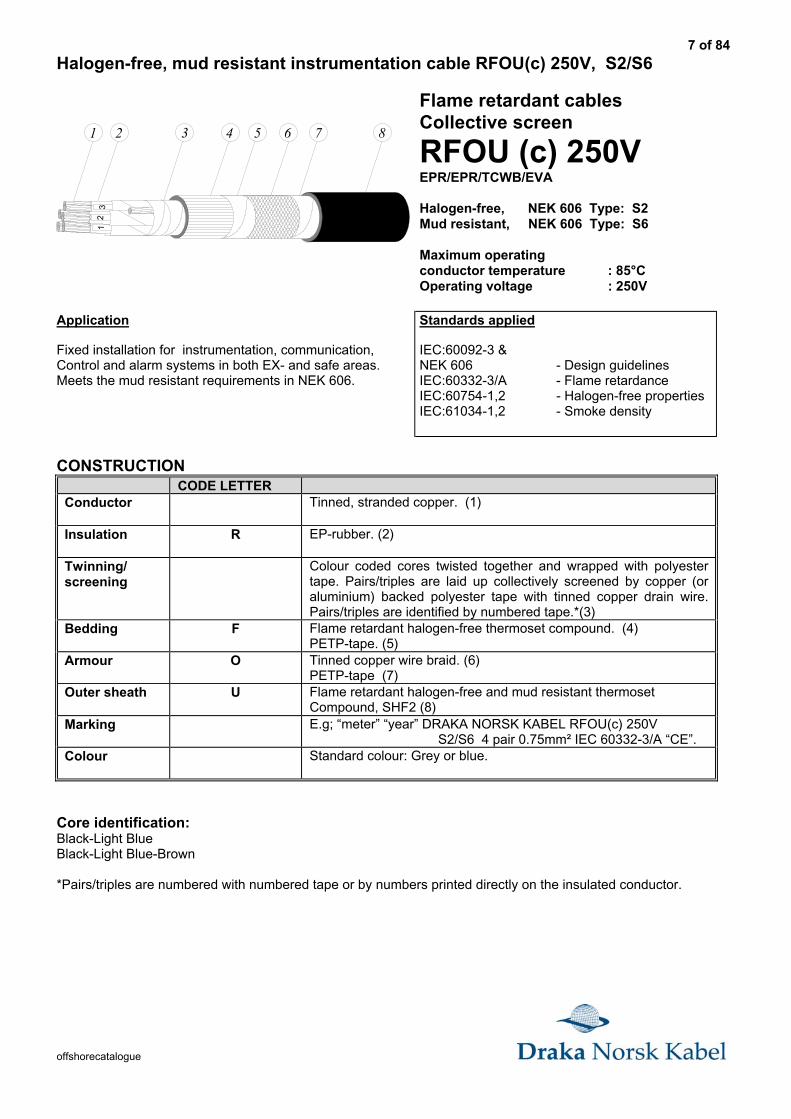
Halogen-free, mud resistant instrumentation cable RFOU(c) 250V, S2/S6
1 2
45
31
2
876543
Flame retardant cablesCollective screen
RFOU (c) 250VEPR/EPR/TCWB/EVA
Halogen-free, NEK 606 Type: S2Mud resistant, NEK 606 Type: S6
Maximum operatingconductor temperature : 85°COperating voltage : 250V
Application
Fixed installation for instrumentation, communication,Control and alarm systems in both EX- and safe areas.Meets the mud resistant requirements in NEK 606.
Standards applied
IEC:60092-3 &NEK 606 - Design guidelinesIEC:60332-3/A - Flame retardanceIEC:60754-1,2 - Halogen-free propertiesIEC:61034-1,2 - Smoke density
CONSTRUCTIONCODE LETTER
Conductor Tinned, stranded copper. (1)
Insulation R EP-rubber. (2)
Twinning/screening
Colour coded cores twisted together and wrapped with polyestertape. Pairs/triples are laid up collectively screened by copper (oraluminium) backed polyester tape with tinned copper drain wire.Pairs/triples are identified by numbered tape.*(3)
Bedding F Flame retardant halogen-free thermoset compound. (4)PETP-tape. (5)
Armour O Tinned copper wire braid. (6)PETP-tape (7)
Outer sheath U Flame retardant halogen-free and mud resistant thermosetCompound, SHF2 (8)
Marking E.g; “meter” “year” DRAKA NORSK KABEL RFOU(c) 250V S2/S6 4 pair 0.75mm² IEC 60332-3/A “CE”.
Colour Standard colour: Grey or blue.
Core identification:Black-Light BlueBlack-Light Blue-Brown
*Pairs/triples are numbered with numbered tape or by numbers printed directly on the insulated conductor.
8 of 84
offshorecatalogue
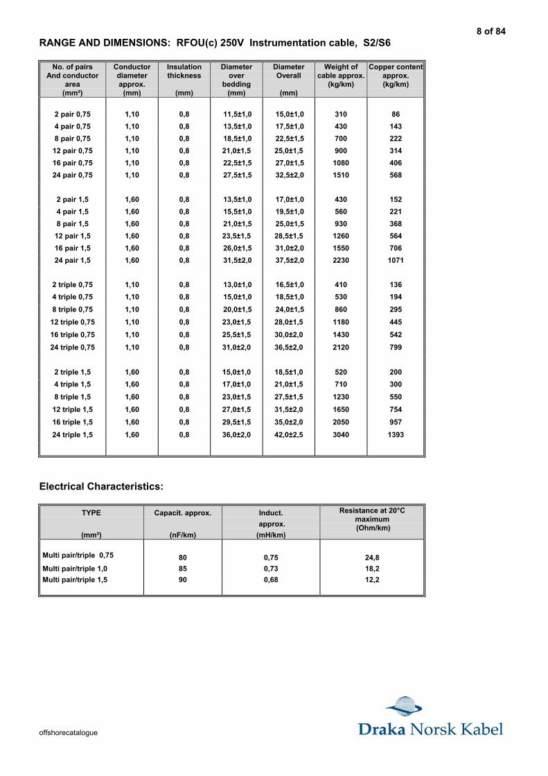
RANGE AND DIMENSIONS: RFOU(c) 250V Instrumentation cable, S2/S6
No. of pairsAnd conductor
area(mm²)
Conductordiameterapprox.
(mm)
Insulationthickness
(mm)
Diameterover
bedding(mm)
DiameterOverall
(mm)
Weight ofcable approx.
(kg/km)
Copper contentapprox.(kg/km)
2 pair 0,75 1,10 0,8 11,5±1,0 15,0±1,0 310 86
4 pair 0,75 1,10 0,8 13,5±1,0 17,5±1,0 430 143
8 pair 0,75 1,10 0,8 18,5±1,0 22,5±1,5 700 222
12 pair 0,75 1,10 0,8 21,0±1,5 25,0±1,5 900 314
16 pair 0,75 1,10 0,8 22,5±1,5 27,0±1,5 1080 406
24 pair 0,75 1,10 0,8 27,5±1,5 32,5±2,0 1510 568
2 pair 1,5 1,60 0,8 13,5±1,0 17,0±1,0 430 152
4 pair 1,5 1,60 0,8 15,5±1,0 19,5±1,0 560 221
8 pair 1,5 1,60 0,8 21,0±1,5 25,0±1,5 930 368
12 pair 1,5 1,60 0,8 23,5±1,5 28,5±1,5 1260 564
16 pair 1,5 1,60 0,8 26,0±1,5 31,0±2,0 1550 706
24 pair 1,5 1,60 0,8 31,5±2,0 37,5±2,0 2230 1071
2 triple 0,75 1,10 0,8 13,0±1,0 16,5±1,0 410 136
4 triple 0,75 1,10 0,8 15,0±1,0 18,5±1,0 530 194
8 triple 0,75 1,10 0,8 20,0±1,5 24,0±1,5 860 295
12 triple 0,75 1,10 0,8 23,0±1,5 28,0±1,5 1180 445
16 triple 0,75 1,10 0,8 25,5±1,5 30,0±2,0 1430 542
24 triple 0,75 1,10 0,8 31,0±2,0 36,5±2,0 2120 799
2 triple 1,5 1,60 0,8 15,0±1,0 18,5±1,0 520 200
4 triple 1,5 1,60 0,8 17,0±1,0 21,0±1,5 710 300
8 triple 1,5 1,60 0,8 23,0±1,5 27,5±1,5 1230 550
12 triple 1,5 1,60 0,8 27,0±1,5 31,5±2,0 1650 754
16 triple 1,5 1,60 0,8 29,5±1,5 35,0±2,0 2050 957
24 triple 1,5 1,60 0,8 36,0±2,0 42,0±2,5 3040 1393
Electrical Characteristics:
TYPE
(mm²)
Capacit. approx.
(nF/km)
Induct.
approx.
(mH/km)
Resistance at 20°Cmaximum (Ohm/km)
Multi pair/triple 0,75 80 0,75 24,8
Multi pair/triple 1,0 85 0,73 18,2
Multi pair/triple 1,5 90 0,68 12,2
9 of 84
offshorecatalogue
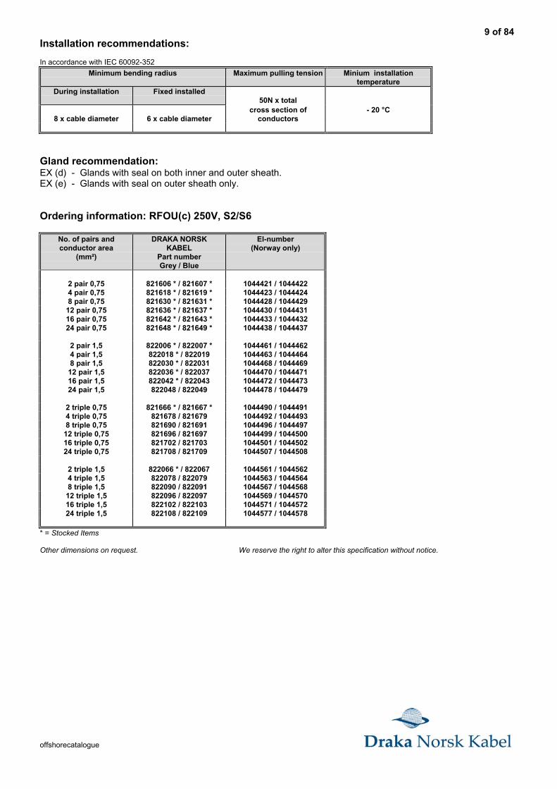
Installation recommendations:
In accordance with IEC 60092-352
Minimum bending radius Maximum pulling tension Minium installationtemperature
During installation Fixed installed50N x total
8 x cable diameter 6 x cable diametercross section of
conductors- 20 °C
Gland recommendation:EX (d) - Glands with seal on both inner and outer sheath.EX (e) - Glands with seal on outer sheath only.
Ordering information: RFOU(c) 250V, S2/S6
No. of pairs andconductor area
(mm²)
DRAKA NORSKKABEL
Part numberGrey / Blue
El-number(Norway only)
2 pair 0,75 821606 * / 821607 * 1044421 / 10444224 pair 0,75 821618 * / 821619 * 1044423 / 10444248 pair 0,75 821630 * / 821631 * 1044428 / 1044429
12 pair 0,75 821636 * / 821637 * 1044430 / 104443116 pair 0,75 821642 * / 821643 * 1044433 / 104443224 pair 0,75 821648 * / 821649 * 1044438 / 1044437
2 pair 1,5 822006 * / 822007 * 1044461 / 10444624 pair 1,5 822018 * / 822019 1044463 / 10444648 pair 1,5 822030 * / 822031 1044468 / 1044469
12 pair 1,5 822036 * / 822037 1044470 / 104447116 pair 1,5 822042 * / 822043 1044472 / 104447324 pair 1,5 822048 / 822049 1044478 / 1044479
2 triple 0,75 821666 * / 821667 * 1044490 / 10444914 triple 0,75 821678 / 821679 1044492 / 10444938 triple 0,75 821690 / 821691 1044496 / 1044497
12 triple 0,75 821696 / 821697 1044499 / 104450016 triple 0,75 821702 / 821703 1044501 / 104450224 triple 0,75 821708 / 821709 1044507 / 1044508
2 triple 1,5 822066 * / 822067 1044561 / 10445624 triple 1,5 822078 / 822079 1044563 / 10445648 triple 1,5 822090 / 822091 1044567 / 1044568
12 triple 1,5 822096 / 822097 1044569 / 104457016 triple 1,5 822102 / 822103 1044571 / 104457224 triple 1,5 822108 / 822109 1044577 / 1044578
* = Stocked Items
Other dimensions on request. We reserve the right to alter this specification without notice.
10 of 84
offshorecatalogue
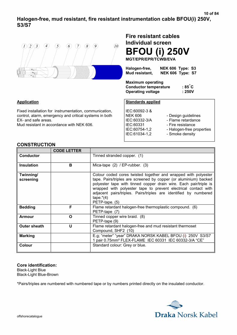
Halogen-free, mud resistant, fire resistant instrumentation cable BFOU(i) 250V,S3/S7
971 2 3 4 5 6 8 10
54
31
2
Fire resistant cablesIndividual screen
BFOU (i) 250VMGT/EPR/EPR/TCWB/EVA
Halogen-free, NEK 606 Type: S3Mud resistant, NEK 606 Type: S7
Maximum operatingConductor temperature : 85°COperating voltage : 250V
Application
Fixed installation for instrumentation, communication,control, alarm, emergency and critical systems in bothEX- and safe areas.Mud resistant in accordance with NEK 606.
Standards applied
IEC:60092-3 &NEK 606 - Design guidelinesIEC:60332-3/A - Flame retardanceIEC:60331 - Fire resistanceIEC:60754-1,2 - Halogen-free propertiesIEC:61034-1,2 - Smoke density
CONSTRUCTIONCODE LETTER
Conductor Tinned stranded copper. (1)
Insulation B Mica-tape (2) / EP-rubber. (3)
Twinning/screening
Colour coded cores twisted together and wrapped with polyestertape. Pairs/triples are screened by copper (or aluminium) backedpolyester tape with tinned copper drain wire. Each pair/triple iswrapped with polyester tape to prevent electrical contact withadjacent pairs/triples. Pairs/triples are identified by numberedtape.*(4)PETP-tape. (5)
Bedding F Flame retardant halogen-free thermoplastic compound. (6)PETP-tape (7)
Armour O Tinned copper wire braid. (8)PETP-tape (9)
Outer sheath U Flame retardant halogen-free and mud resistant thermosetCompound, SHF2 (10)
Marking E.g; “meter” “year” DRAKA NORSK KABEL BFOU (i) 250V S3/S71 pair 0.75mm² FLEX-FLAME IEC 60331 IEC 60332-3/A “CE”
Colour Standard colour: Grey or blue.
Core identification:Black-Light BlueBlack-Light Blue-Brown
*Pairs/triples are numbered with numbered tape or by numbers printed directly on the insulated conductor.
11 of 84
offshorecatalogue
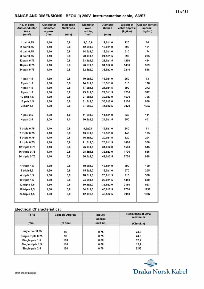
RANGE AND DIMENSIONS: BFOU (i) 250V Instrumentation cable, S3/S7
No. of pairsAnd conductor
Area(mm²)
Conductordiameterapprox.
(mm)
Insulationthickness
(mm)
Diameterover
bedding(mm)
DiameterOverall
(mm)
Weight ofcable approx.
(kg/km)
Copper contentapprox.(kg/km)
1 pair 0,75 1,10 0,8 9,0±0,8 12,0±1,0 220 64
2 pair 0,75 1,10 0,8 12,5±1,0 16,0±1,0 390 121
4 pair 0,75 1,10 0,8 14,5±1,0 18,5±1,0 510 174
8 pair 0,75 1,10 0,8 20,0±1,5 24,5±1,5 890 285
12 pair 0,75 1,10 0,8 23,5±1,5 28,5±1,5 1250 434
16 pair 0,75 1,10 0,8 26,5±1,5 31,5±2,0 1490 529
24 pair 0,75 1,10 0,8 32,5±2,0 38,5±2,0 2210 818
1 pair 1,5 1,60 0,8 10,0±1,0 13,0±1,0 250 73
2 pair 1,5 1,60 0,8 14,5±1,0 18,5±1,0 510 176
4 pair 1,5 1,60 0,8 17,0±1,5 21,0±1,5 690 272
8 pair 1,5 1,60 0,8 23,0±1,5 27,5±1,5 1230 512
12 pair 1,5 1,60 0,8 27,0±1,5 32,0±2,0 1670 706
16 pair 1,5 1,60 0,8 31,0±2,0 36,0±2,0 2100 900
24pair 1,5 1,60 0,8 37,5±2,0 44,0±2,5 3020 1352
1 pair 2,5 2,00 1,0 11,5±1,0 14,5±1,0 330 111
4 pair 2,5 2,00 1,0 20,5±1,5 24,5±1,5 950 401
1 triple 0,75 1,10 0,8 9,5±0,8 12,5±1,0 240 71
2 triple 0,75 1,10 0,8 13,5±1,0 17,5±1,0 440 135
4 triple 0,75 1,10 0,8 16,5±1,0 20,0±1,5 620 204
8 triple 0,75 1,10 0,8 21,5±1,5 26,0±1,5 1080 358
12 triple 0,75 1,10 0,8 26,0±1,5 31,0±2,0 1540 545
16 triple 0,75 1,10 0,8 28,5±1,5 33,5±2,0 1790 666
24 triple 0,75 1,10 0,8 36,0±2,0 42,0±2,5 2720 988
1 triple 1,5 1,60 0,8 10,5±1,0 13,5±1,0 300 100
2 triple1,5 1,60 0,8 15,5±1,0 19,5±1,0 570 205
4 triple 1,5 1,60 0,8 18,5±1,0 23,0±1,5 910 388
8 triple 1,5 1,60 0,8 24,5±1,5 29,0±1,5 1440 630
12 triple 1,5 1,60 0,8 30,5±2,0 35,5±2,0 2150 923
16 triple 1,5 1,60 0,8 34,0±2,0 40,0±2,5 2700 1236
24 triple 1,5 1,60 0,8 42,0±2,5 48,5±2,5 3950 1802
Electrical Characteristics:TYPE
(mm²)
Capacit. Approx.
(nF/km)
Induct.
approx.
(mH/km)
Resistance at 20°Cmaximum
(Ohm/km)
Single pair 0,75 90 0,75 24,8
Single triple 0,75 90 0,75 24,8
Single pair 1,5 110 0,68 12,2
Single triple 1,5 110 0,68 12,2
Single pair 2,5 120 0,70 7,56
12 of 84
offshorecatalogue
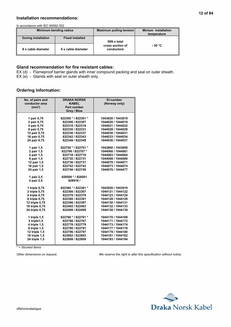
Installation recommendations:
In accordance with IEC 60092-352
Minimum bending radius Maximum pulling tension Minium installationtemperature
During installation Fixed installed50N x total
8 x cable diameter 6 x cable diametercross section of
conductors- 20 °C
Gland recommendation for fire resistant cables:EX (d) - Flameproof barrier glands with inner compound packing and seal on outer sheath.EX (e) - Glands with seal on outer sheath only.
Ordering information:
No. of pairs andconductor area
(mm²)
DRAKA NORSKKABEL
Part numberGrey / Blue
El-number(Norway only)
1 pair 0,75 822300 * / 822301 * 1043820 / 10438192 pair 0,75 822306 / 822307 1044020 / 10440194 pair 0,75 822318 / 822319 1044021 / 10440228 pair 0,75 822330 / 822331 1044028 / 1044029
12 pair 0,75 822336 / 822337 1044030 / 104403116 pair 0,75 822342 / 822343 1044033 / 104403424 pair 0,75 822348 / 822349 1044036 / 1044037
1 pair 1,5 822700 * / 822701 * 1043860 / 10438592 pair 1,5 822706 / 822707 * 1044060 / 10440614 pair 1,5 822718 / 822719 1044063 / 10440648 pair 1,5 822730 / 822731 1044068 / 1044069
12 pair 1,5 822736 / 822737 1044070 / 104407116 pair 1,5 822742 / 822743 1044073 / 104407424 pair 1,5 822748 / 822749 1044076 / 1044477
1 pair 2,5 828500 * / 8285014 pair 2,5 828918 /
1 triple 0,75 822360 * / 822361 * 1043920 / 10439192 triple 0,75 822366 / 822367 1044121 / 10441224 triple 0,75 822378 / 822379 1044123 / 10441248 triple 0,75 822390 / 822391 1044128 / 1044129
12 triple 0,75 822396 / 822397 1044130 / 104413116 triple 0,75 822402 / 822403 1044132 / 104413324 triple 0,75 822408 / 822409 1044138 / 1044139
1 triple 1,5 822760 * / 822761 * 1044170 / 10441692 triple1,5 822766 / 822767 1044171 / 10441724 triple 1,5 822778 / 822779 1044173 / 10441748 triple 1,5 822790 / 822791 1044177 / 1044178
12 triple 1,5 822796 / 822797 1044179 / 104418016 triple 1,5 822802 / 822803 1044181 / 104418224 triple 1,5 822808 / 822809 1044193 / 1044194
* = Stocked Items
Other dimensions on request. We reserve the right to alter this specification without notice.
13 of 84
offshorecatalogue
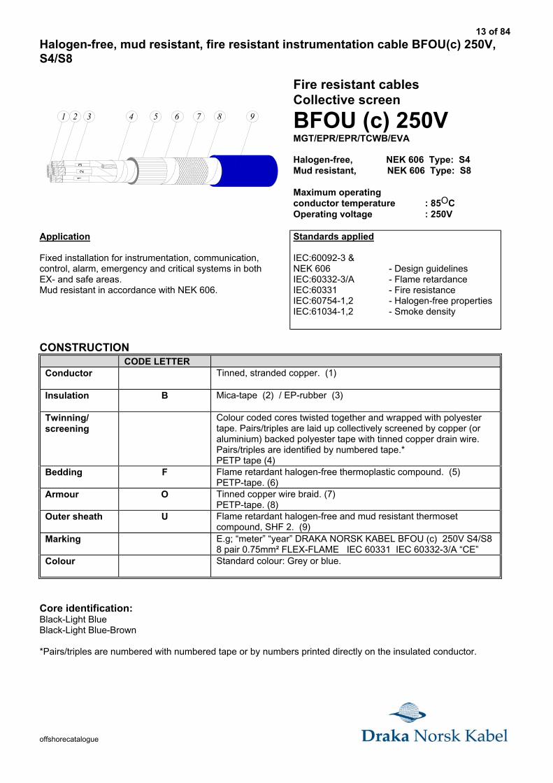
Halogen-free, mud resistant, fire resistant instrumentation cable BFOU(c) 250V,S4/S8
Fire resistant cablesCollective screen
BFOU (c) 250VMGT/EPR/EPR/TCWB/EVA
Halogen-free, NEK 606 Type: S4Mud resistant, NEK 606 Type: S8
Maximum operatingconductor temperature : 85OCOperating voltage : 250V
Application
Fixed installation for instrumentation, communication,control, alarm, emergency and critical systems in bothEX- and safe areas.Mud resistant in accordance with NEK 606.
Standards applied
IEC:60092-3 &NEK 606 - Design guidelinesIEC:60332-3/A - Flame retardanceIEC:60331 - Fire resistanceIEC:60754-1,2 - Halogen-free propertiesIEC:61034-1,2 - Smoke density
CONSTRUCTIONCODE LETTER
Conductor Tinned, stranded copper. (1)
Insulation B Mica-tape (2) / EP-rubber (3)
Twinning/screening
Colour coded cores twisted together and wrapped with polyestertape. Pairs/triples are laid up collectively screened by copper (oraluminium) backed polyester tape with tinned copper drain wire.Pairs/triples are identified by numbered tape.*PETP tape (4)
Bedding F Flame retardant halogen-free thermoplastic compound. (5)PETP-tape. (6)
Armour O Tinned copper wire braid. (7)PETP-tape. (8)
Outer sheath U Flame retardant halogen-free and mud resistant thermosetcompound, SHF 2. (9)
Marking E.g; “meter” “year” DRAKA NORSK KABEL BFOU (c) 250V S4/S88 pair 0.75mm² FLEX-FLAME IEC 60331 IEC 60332-3/A “CE”
Colour Standard colour: Grey or blue.
Core identification:Black-Light BlueBlack-Light Blue-Brown
*Pairs/triples are numbered with numbered tape or by numbers printed directly on the insulated conductor.
1 2 3 4 5 6 7 98
54
31
2
14 of 84
offshorecatalogue
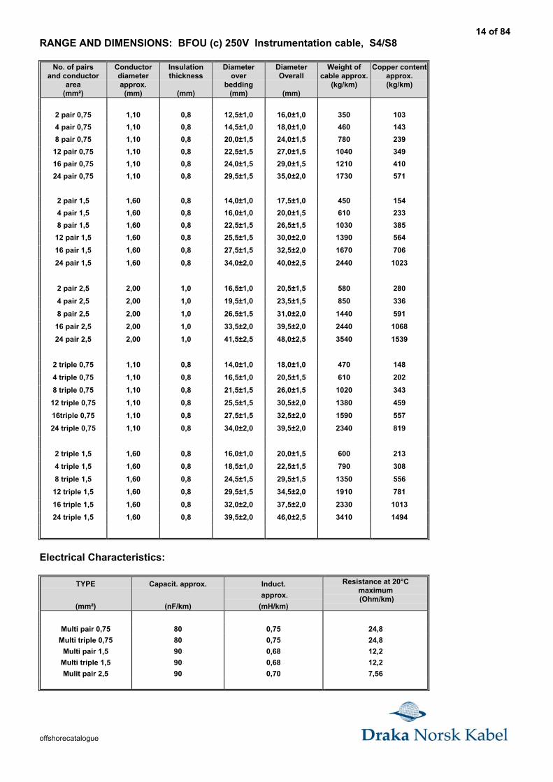
RANGE AND DIMENSIONS: BFOU (c) 250V Instrumentation cable, S4/S8
No. of pairsand conductor
area(mm²)
Conductordiameterapprox.
(mm)
Insulationthickness
(mm)
Diameterover
bedding(mm)
DiameterOverall
(mm)
Weight ofcable approx.
(kg/km)
Copper contentapprox.(kg/km)
2 pair 0,75 1,10 0,8 12,5±1,0 16,0±1,0 350 103
4 pair 0,75 1,10 0,8 14,5±1,0 18,0±1,0 460 143
8 pair 0,75 1,10 0,8 20,0±1,5 24,0±1,5 780 239
12 pair 0,75 1,10 0,8 22,5±1,5 27,0±1,5 1040 349
16 pair 0,75 1,10 0,8 24,0±1,5 29,0±1,5 1210 410
24 pair 0,75 1,10 0,8 29,5±1,5 35,0±2,0 1730 571
2 pair 1,5 1,60 0,8 14,0±1,0 17,5±1,0 450 154
4 pair 1,5 1,60 0,8 16,0±1,0 20,0±1,5 610 233
8 pair 1,5 1,60 0,8 22,5±1,5 26,5±1,5 1030 385
12 pair 1,5 1,60 0,8 25,5±1,5 30,0±2,0 1390 564
16 pair 1,5 1,60 0,8 27,5±1,5 32,5±2,0 1670 706
24 pair 1,5 1,60 0,8 34,0±2,0 40,0±2,5 2440 1023
2 pair 2,5 2,00 1,0 16,5±1,0 20,5±1,5 580 280
4 pair 2,5 2,00 1,0 19,5±1,0 23,5±1,5 850 336
8 pair 2,5 2,00 1,0 26,5±1,5 31,0±2,0 1440 591
16 pair 2,5 2,00 1,0 33,5±2,0 39,5±2,0 2440 1068
24 pair 2,5 2,00 1,0 41,5±2,5 48,0±2,5 3540 1539
2 triple 0,75 1,10 0,8 14,0±1,0 18,0±1,0 470 148
4 triple 0,75 1,10 0,8 16,5±1,0 20,5±1,5 610 202
8 triple 0,75 1,10 0,8 21,5±1,5 26,0±1,5 1020 343
12 triple 0,75 1,10 0,8 25,5±1,5 30,5±2,0 1380 459
16triple 0,75 1,10 0,8 27,5±1,5 32,5±2,0 1590 557
24 triple 0,75 1,10 0,8 34,0±2,0 39,5±2,0 2340 819
2 triple 1,5 1,60 0,8 16,0±1,0 20,0±1,5 600 213
4 triple 1,5 1,60 0,8 18,5±1,0 22,5±1,5 790 308
8 triple 1,5 1,60 0,8 24,5±1,5 29,5±1,5 1350 556
12 triple 1,5 1,60 0,8 29,5±1,5 34,5±2,0 1910 781
16 triple 1,5 1,60 0,8 32,0±2,0 37,5±2,0 2330 1013
24 triple 1,5 1,60 0,8 39,5±2,0 46,0±2,5 3410 1494
Electrical Characteristics:
TYPE
(mm²)
Capacit. approx.
(nF/km)
Induct.
approx.
(mH/km)
Resistance at 20°Cmaximum (Ohm/km)
Multi pair 0,75 80 0,75 24,8
Multi triple 0,75 80 0,75 24,8
Multi pair 1,5 90 0,68 12,2
Multi triple 1,5 90 0,68 12,2
Mulit pair 2,5 90 0,70 7,56
15 of 84
offshorecatalogue
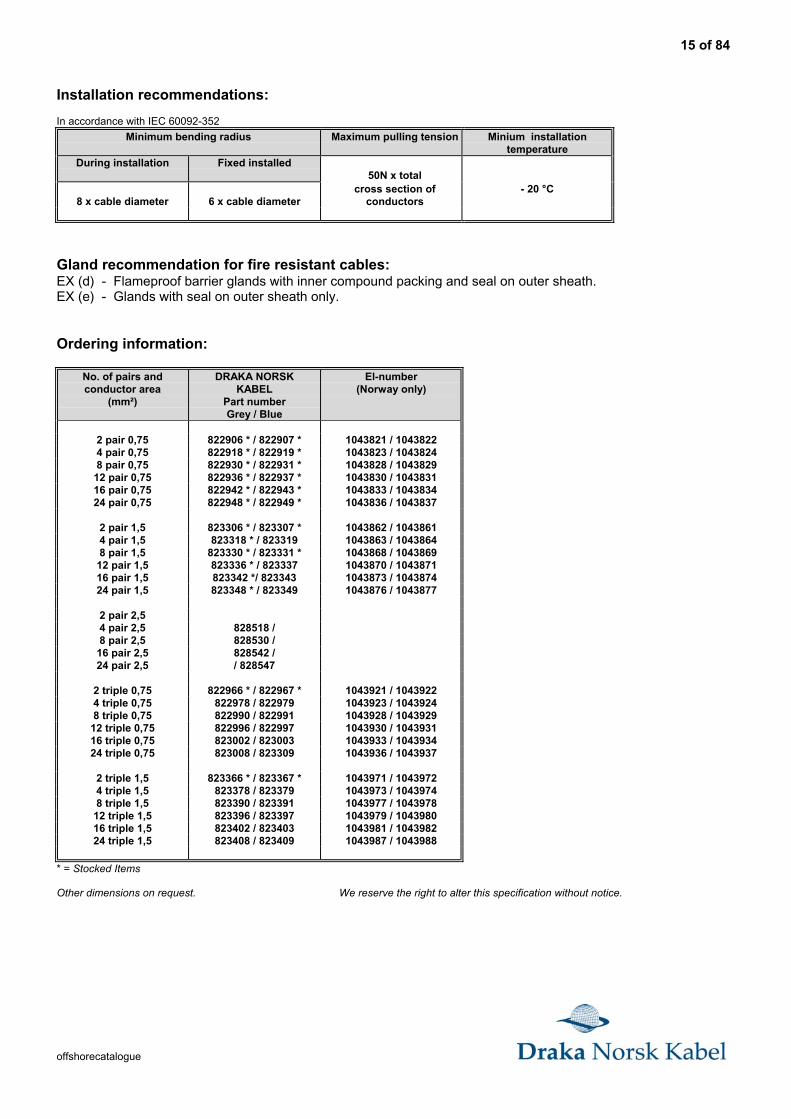
Installation recommendations:
In accordance with IEC 60092-352
Minimum bending radius Maximum pulling tension Minium installationtemperature
During installation Fixed installed50N x total
8 x cable diameter 6 x cable diametercross section of
conductors- 20 °C
Gland recommendation for fire resistant cables:EX (d) - Flameproof barrier glands with inner compound packing and seal on outer sheath.EX (e) - Glands with seal on outer sheath only.
Ordering information:
No. of pairs andconductor area
(mm²)
DRAKA NORSKKABEL
Part numberGrey / Blue
El-number(Norway only)
2 pair 0,75 822906 * / 822907 * 1043821 / 10438224 pair 0,75 822918 * / 822919 * 1043823 / 10438248 pair 0,75 822930 * / 822931 * 1043828 / 1043829
12 pair 0,75 822936 * / 822937 * 1043830 / 104383116 pair 0,75 822942 * / 822943 * 1043833 / 104383424 pair 0,75 822948 * / 822949 * 1043836 / 1043837
2 pair 1,5 823306 * / 823307 * 1043862 / 10438614 pair 1,5 823318 * / 823319 1043863 / 10438648 pair 1,5 823330 * / 823331 * 1043868 / 1043869
12 pair 1,5 823336 * / 823337 1043870 / 104387116 pair 1,5 823342 */ 823343 1043873 / 104387424 pair 1,5 823348 * / 823349 1043876 / 1043877
2 pair 2,54 pair 2,5 828518 /8 pair 2,5 828530 /
16 pair 2,5 828542 /24 pair 2,5 / 828547
2 triple 0,75 822966 * / 822967 * 1043921 / 10439224 triple 0,75 822978 / 822979 1043923 / 10439248 triple 0,75 822990 / 822991 1043928 / 1043929
12 triple 0,75 822996 / 822997 1043930 / 104393116 triple 0,75 823002 / 823003 1043933 / 104393424 triple 0,75 823008 / 823309 1043936 / 1043937
2 triple 1,5 823366 * / 823367 * 1043971 / 10439724 triple 1,5 823378 / 823379 1043973 / 10439748 triple 1,5 823390 / 823391 1043977 / 1043978
12 triple 1,5 823396 / 823397 1043979 / 104398016 triple 1,5 823402 / 823403 1043981 / 104398224 triple 1,5 823408 / 823409 1043987 / 1043988
* = Stocked Items
Other dimensions on request. We reserve the right to alter this specification without notice.
16 of 84
offshorecatalogue
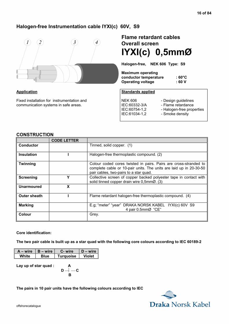
Halogen-free Instrumentation cable IYXI(c) 60V, S9
1 2 3 4Flame retardant cablesOverall screen
IYXI(c) 0,5mmØHalogen-free, NEK 606 Type: S9
Maximum operatingconductor temperature : 60°COperating voltage : 60 V
Application
Fixed installation for instrumentation andcommunication systems in safe areas.
Standards applied
NEK 606 - Design guidelinesIEC:60332-3/A - Flame retardanceIEC:60754-1,2 - Halogen-free propertiesIEC:61034-1,2 - Smoke density
CONSTRUCTIONCODE LETTER
Conductor Tinned, solid copper. (1)
Insulation I Halogen-free thermoplastic compound. (2)
Twinning Colour coded cores twisted in pairs. Pairs are cross-stranded tocomplete cable or 10-pair units. The units are laid up in 20-30-50pair cables, two-pairs to a star quad.
Screening Y Collective screen of copper backed polyester tape in contact withsolid tinned copper drain wire 0,5mmØ. (3)
Unarmoured X
Outer sheath I Flame retardant halogen-free thermoplastic compound. (4)
Marking E.g; “meter” “year” DRAKA NORSK KABEL IYXI(c) 60V S9 4 pair 0.5mmØ “CE”
Colour Grey.
Core identification:
The two pair cable is built up as a star quad with the following core colours according to IEC 60189-2
A – wire B – wire C- wire D – wireWhite Blue Turquoise Violet
Lay up of star quad : A D C B
The pairs in 10 pair units have the following colours according to IEC
17 of 84
offshorecatalogue
60189 - 2 :
Pair no: A - wire B - wire1 White Blue2 White Orange3 White Green4 White Brown5 White Grey6 Red Blue7 Red Orange8 Red Green9 Red Brown
10 Red Grey
Each 10 pair unit is identified by a coloured polyester tape in open spiral. The tape has the following colours:
Unit no; 1 2 3 4 5Colour Blue Orange Green Brown Grey
RANGE AND DIMENSIONS: IYXI(c) 60V Instrumentation cable, S9
No. of pairsAnd conductor
Diam.(mmØ)
Conductordiameterapprox.(mmØ)
Insulationthickness
(mm)
DiameterOverall
(mm)
Weight of cableapprox.(kg/km)
Copper contentapprox.(kg/km)
1 pair 0,5 0,50 0,2 5,0±0,5 30 5,5
2 pair 0,5 0,50 0,2 5,5±0,5 35 8,9
4 pair 0,5 0,50 0,2 7,0±0,5 55 16
10 pair 0,5 0,50 0,2 8,5±0,8 90 37
20 pair 0,5 0,50 0,2 11,0±1,0 148 72
30 pair 0,5 0,50 0,2 13,5±1,0 210 107
50 pair 0,5 0,50 0,2 15,5±1,0 320 177
Electrical Characteristics:
Type
(mmØ)
Capacit. approx.
(nF/km)
Induct.
Approx.
(mH/km)
Resistance at 20°Cmaximum (Ohm/km)
One pair 0,5 90 0,61 95,0
Two pair 0,5 80 0,61 95,0
Four pair and above 0,5 70 0,61 95,0
18 of 84
offshorecatalogue
Installation recommendations:
In accordance with IEC 60092-352
Minimum bending radius Maximum pullingtension
Minium installationtemperature
During installation Fixed installed25 N x total
20 x cable diameter 10 x cable diametercross section of
conductors- 10 °C
Ordering information:
No. of pairs andconductor diam.
(mmØ)
DRAKA NORSKKABEL
Part number
El-number(Norway only)
1 pair 0,5 825900 * 10447902 pair 0,5 825901 * 10447914 pair 0,5 825902 * 1044792
10 pair 0,5 825904 * 104479420 pair 0,5 825906 * 104479530 pair 0,5 825908 * 104479650 pair 0,5 825910 1044797
* = Stocked Items
We reserve the right to alter this specification without notice.
19 of 84
offshorecatalogue
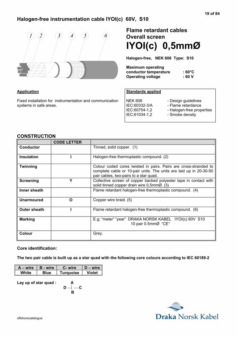
Halogen-free instrumentation cable IYOI(c) 60V, S10
1 2 3 4 65Flame retardant cablesOverall screen
IYOI(c) 0,5mmØHalogen-free, NEK 606 Type: S10
Maximum operatingconductor temperature : 60°COperating voltage : 60 V
Application
Fixed installation for instrumentation and communicationsystems in safe areas.
Standards applied
NEK 606 - Design guidelinesIEC:60332-3/A - Flame retardanceIEC:60754-1,2 - Halogen-free propertiesIEC:61034-1,2 - Smoke density
CONSTRUCTIONCODE LETTER
Conductor Tinned, solid copper. (1)
Insulation I Halogen-free thermoplastic compound. (2)
Twinning Colour coded cores twisted in pairs. Pairs are cross-stranded tocomplete cable or 10-pair units. The units are laid up in 20-30-50pair cables, two-pairs to a star quad.
Screening Y Collective screen of copper backed polyester tape in contact withsolid tinned copper drain wire 0,5mmØ. (3)
Inner sheath Flame retardant halogen-free thermoplastic compound. (4)
Unarmoured O Copper wire braid. (5)
Outer sheath I Flame retardant halogen-free thermoplastic compound. (6)
Marking E.g; “meter” “year” DRAKA NORSK KABEL IYOI(c) 60V S10 10 pair 0.5mmØ “CE”
Colour Grey.
Core identification:
The two pair cable is built up as a star quad with the following core colours according to IEC 60189-2
A – wire B - wire C- wire D – wireWhite Blue Turquoise Violet
Lay up of star quad : A D C B
20 of 84
offshorecatalogue
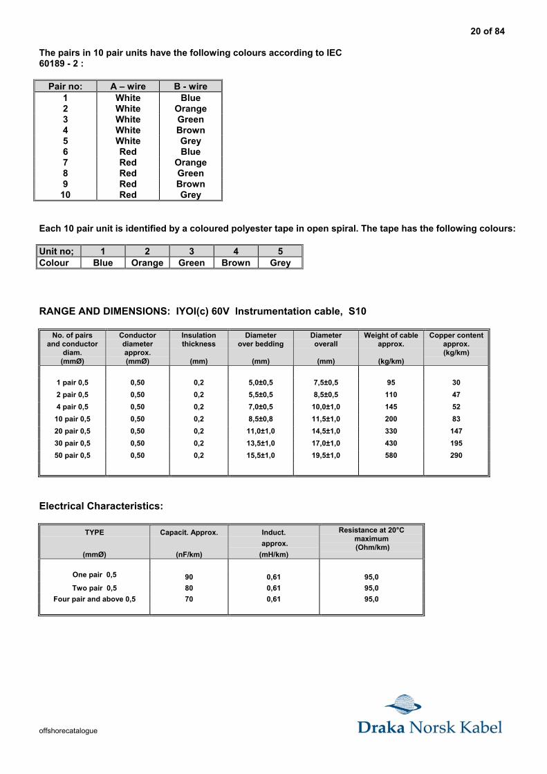
The pairs in 10 pair units have the following colours according to IEC60189 - 2 :
Pair no: A – wire B - wire1 White Blue2 White Orange3 White Green4 White Brown5 White Grey6 Red Blue7 Red Orange8 Red Green9 Red Brown
10 Red Grey
Each 10 pair unit is identified by a coloured polyester tape in open spiral. The tape has the following colours:
Unit no; 1 2 3 4 5Colour Blue Orange Green Brown Grey
RANGE AND DIMENSIONS: IYOI(c) 60V Instrumentation cable, S10
No. of pairsand conductor
diam.(mmØ)
Conductordiameterapprox.(mmØ)
Insulationthickness
(mm)
Diameterover bedding
(mm)
Diameteroverall
(mm)
Weight of cableapprox.
(kg/km)
Copper contentapprox.(kg/km)
1 pair 0,5 0,50 0,2 5,0±0,5 7,5±0,5 95 30
2 pair 0,5 0,50 0,2 5,5±0,5 8,5±0,5 110 47
4 pair 0,5 0,50 0,2 7,0±0,5 10,0±1,0 145 52
10 pair 0,5 0,50 0,2 8,5±0,8 11,5±1,0 200 83
20 pair 0,5 0,50 0,2 11,0±1,0 14,5±1,0 330 147
30 pair 0,5 0,50 0,2 13,5±1,0 17,0±1,0 430 195
50 pair 0,5 0,50 0,2 15,5±1,0 19,5±1,0 580 290
Electrical Characteristics:
TYPE
(mmØ)
Capacit. Approx.
(nF/km)
Induct.
approx.
(mH/km)
Resistance at 20°Cmaximum (Ohm/km)
One pair 0,5 90 0,61 95,0
Two pair 0,5 80 0,61 95,0
Four pair and above 0,5 70 0,61 95,0
21 of 84
offshorecatalogue
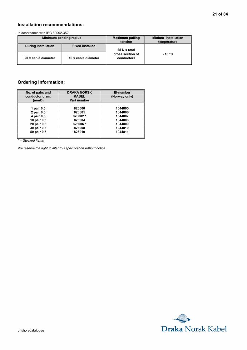
Installation recommendations:
In accordance with IEC 60092-352
Minimum bending radius Maximum pullingtension
Minium installationtemperature
During installation Fixed installed25 N x total
20 x cable diameter 10 x cable diametercross section of
conductors- 10 °C
Ordering information:
No. of pairs andconductor diam.
(mmØ)
DRAKA NORSKKABEL
Part number
El-number(Norway only)
1 pair 0,5 826000 10448052 pair 0,5 826001 10448064 pair 0,5 826002 * 1044807
10 pair 0,5 826004 104480820 pair 0,5 826006 * 104480930 pair 0,5 826008 104481050 pair 0,5 826010 1044811
* = Stocked Items
We reserve the right to alter this specification without notice.
22 of 84
offshorecatalogue
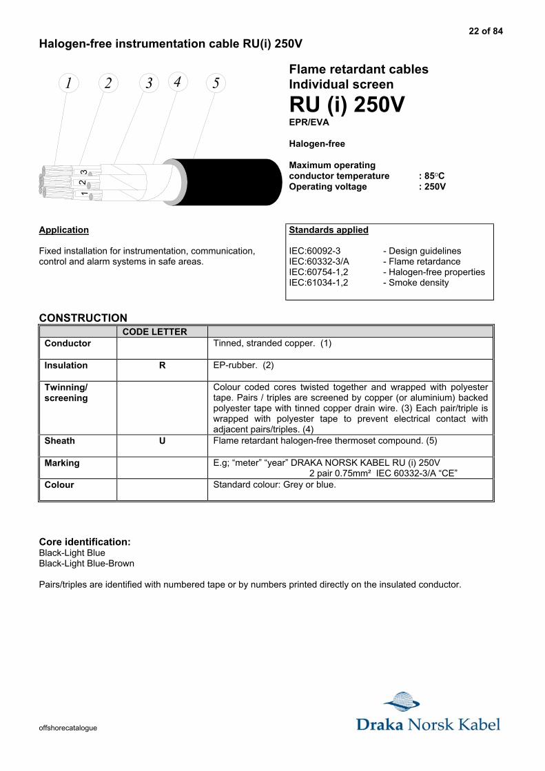
Halogen-free instrumentation cable RU(i) 250V
51 2 31
13
12
4Flame retardant cablesIndividual screen
RU (i) 250VEPR/EVA
Halogen-free
Maximum operatingconductor temperature : 85OCOperating voltage : 250V
Application
Fixed installation for instrumentation, communication,control and alarm systems in safe areas.
Standards applied
IEC:60092-3 - Design guidelinesIEC:60332-3/A - Flame retardanceIEC:60754-1,2 - Halogen-free propertiesIEC:61034-1,2 - Smoke density
CONSTRUCTIONCODE LETTER
Conductor Tinned, stranded copper. (1)
Insulation R EP-rubber. (2)
Twinning/screening
Colour coded cores twisted together and wrapped with polyestertape. Pairs / triples are screened by copper (or aluminium) backedpolyester tape with tinned copper drain wire. (3) Each pair/triple iswrapped with polyester tape to prevent electrical contact withadjacent pairs/triples. (4)
Sheath U Flame retardant halogen-free thermoset compound. (5)
Marking E.g; “meter” “year” DRAKA NORSK KABEL RU (i) 250V 2 pair 0.75mm² IEC 60332-3/A “CE”
Colour Standard colour: Grey or blue.
Core identification:Black-Light BlueBlack-Light Blue-Brown
Pairs/triples are identified with numbered tape or by numbers printed directly on the insulated conductor.

23 of 84
offshorecatalogue
RANGE AND DIMENSIONS: RU (i) 250V Instrumentation cable
No. of pairsand conductor
area(mm²)
Conductordiameterapprox.
(mm)
Insulationthickness
(mm)
DiameterOverall
(mm)
Weight of cableapprox.
kg/km)
Copper contentapprox.(kg/km)
1 pair 0,75 1,10 0,8 8,0±0,8 95 21
2 pair 0,75 1,10 0,8 12,0±1,0 190 42
4 pair 0,75 1,10 0,8 13,5±1,0 280 83
8 pair 0,75 1,10 0,8 18,5±1,0 530 166
12 pair 0,75 1,10 0,8 22,0±1,5 750 249
16 pair 0,75 1,10 0,8 24,5±1,5 950 331
24 pair 0,75 1,10 0,8 30,5±2,0 1420 497
1 pair 1,5 1,10 0,8 9,0±0,8 135 42
2 pair 1,5 1,60 0,8 13,5±1,0 265 84
4 pair 1,5 1,60 0,8 16,0±1,0 415 168
8 pair 1,5 1,60 0,8 21,5±1,5 780 336
12 pair 1,5 1,60 0,8 26,0±1,5 1140 503
16 pair 1,5 1,60 0,8 29,0±1,5 1450 671
24 pair 1,5 1,60 0,8 35,5±2,0 2150 1006
1 triple 0,75 1,10 0,8 8,5±0,8 110 28
2 triple 0,75 1,10 0,8 13,0±1,0 235 56
4 triple 0,75 1,10 0,8 15,5±1,0 360 111
8 triple 0,75 1,10 0,8 20,5±1,5 670 222
12 triple 0,75 1,10 0,8 25,0±1,5 970 333
16 triple 0,75 1,10 0,8 28,0±1,5 1240 444
24 triple 0,75 1,10 0,8 34,5±2,0 1830 665
1 triple 1,5 1,60 0,8 9,5±0,8 165 57
2 triple 1,5 1,60 0,8 15,0±1,0 350 114
4 triple 1,5 1,60 0,8 18,0±1,0 550 227
8 triple 1,5 1,60 0,8 24,0±1,5 1010 453
12 triple 1,5 1,60 0,8 29,5±1,5 1510 680
16 triple 1,5 1,60 0,8 32,5±2,0 1910 905
24 triple 1,5 1,60 0,8 40,5±2,5 2870 1358
Electrical Characteristics:
Type
(mm²)
Capacit. approx.
(nF/km)
Induct.
approx.
(mH/km)
Resistance at 20°Cmaximum (Ohm/km)
Single pair/triple 0,75 90 0,75 24,8
Single pair/triple 1,5 110 0,68 12,2
24 of 84
offshorecatalogue
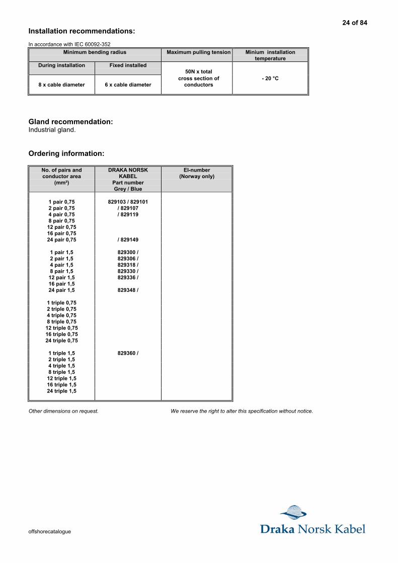
Installation recommendations:
In accordance with IEC 60092-352
Minimum bending radius Maximum pulling tension Minium installationtemperature
During installation Fixed installed50N x total
8 x cable diameter 6 x cable diametercross section of
conductors- 20 °C
Gland recommendation:Industrial gland.
Ordering information:
No. of pairs andconductor area
(mm²)
DRAKA NORSKKABEL
Part numberGrey / Blue
El-number(Norway only)
1 pair 0,75 829103 / 8291012 pair 0,75 / 8291074 pair 0,75 / 8291198 pair 0,75
12 pair 0,7516 pair 0,7524 pair 0,75 / 829149
1 pair 1,5 829300 /2 pair 1,5 829306 /4 pair 1,5 829318 /8 pair 1,5 829330 /
12 pair 1,5 829336 /16 pair 1,524 pair 1,5 829348 /
1 triple 0,752 triple 0,754 triple 0,758 triple 0,75
12 triple 0,7516 triple 0,7524 triple 0,75
1 triple 1,5 829360 /2 triple 1,54 triple 1,58 triple 1,5
12 triple 1,516 triple 1,524 triple 1,5
Other dimensions on request. We reserve the right to alter this specification without notice.
25 of 84
offshorecatalogue
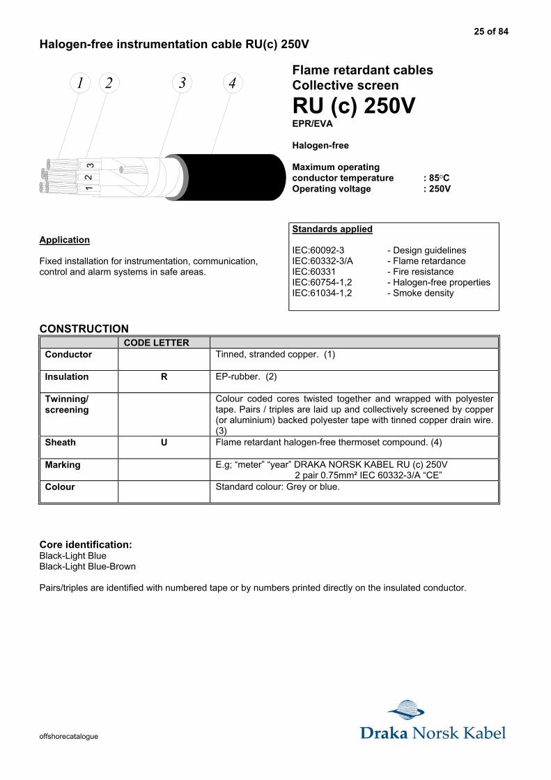
Halogen-free instrumentation cable RU(c) 250V
1 24
53
12
43Flame retardant cablesCollective screen
RU (c) 250VEPR/EVA
Halogen-free
Maximum operatingconductor temperature : 85OCOperating voltage : 250V
Application
Fixed installation for instrumentation, communication,control and alarm systems in safe areas.
Standards applied
IEC:60092-3 - Design guidelinesIEC:60332-3/A - Flame retardanceIEC:60331 - Fire resistanceIEC:60754-1,2 - Halogen-free propertiesIEC:61034-1,2 - Smoke density
CONSTRUCTIONCODE LETTER
Conductor Tinned, stranded copper. (1)
Insulation R EP-rubber. (2)
Twinning/screening
Colour coded cores twisted together and wrapped with polyestertape. Pairs / triples are laid up and collectively screened by copper(or aluminium) backed polyester tape with tinned copper drain wire.(3)
Sheath U Flame retardant halogen-free thermoset compound. (4)
Marking E.g; “meter” “year” DRAKA NORSK KABEL RU (c) 250V 2 pair 0.75mm² IEC 60332-3/A “CE”
Colour Standard colour: Grey or blue.
Core identification:Black-Light BlueBlack-Light Blue-Brown
Pairs/triples are identified with numbered tape or by numbers printed directly on the insulated conductor.
26 of 84
offshorecatalogue
RANGE AND DIMENSIONS: RU (c) 250V Instrumentation cable
No. of pairsand conductor
area(mm²)
Conductordiameterapprox.
(mm)
Insulationthickness
(mm)
Diameteroverall
(mm)
Weight of cableapprox.
kg/km)
Copper contentapprox.(kg/km)
2 pair 0,75 1,10 0,8 11,5±1,0 170 35
4 pair 0,75 1,10 0,8 13,5±1,0 240 63
8 pair 0,75 1,10 0,8 18,5±1,0 440 119
12 pair 0,75 1,10 0,8 21,5±1,5 610 176
16 pair 0,75 1,10 0,8 23,0±1,5 750 232
24 pair 0,75 1,10 0,8 28,5±1,5 1080 344
2 pair 1,5 1,60 0,8 13,5±1,0 245 72
4 pair 1,5 1,60 0,8 16,0±1,0 360 130
8 pair 1,5 1,60 0,8 21,5±1,5 650 248
12 pair 1,5 1,60 0,8 24,5±1,5 910 365
16 pair 1,5 1,60 0,8 27,0±1,5 1130 482
24 pair 1,5 1,60 0,8 33,0±2,0 1670 717
2 triple 0,75 1,10 0,8 13,0±1,0 220 49
4 triple 0,75 1,10 0,8 15,0±1,0 330 91
8 triple 0,75 1,10 0,8 20,5±1,5 590 176
12 triple 0,75 1,10 0,8 24,0±1,5 820 260
16 triple 0,75 1,10 0,8 26,0±1,5 1020 344
24 triple 0,75 1,10 0,8 32,0±2,0 1510 513
2 triple 1,5 1,60 0,8 15,0±1,0 320 101
4 triple 1,5 1,60 0,8 17,5±1,0 480 189
8 triple 1,5 1,60 0,8 23,5±1,5 880 365
12 triple 1,5 1,60 0,8 28,0±1,5 1270 541
16 triple 1,5 1,60 0,8 30,0±2,0 1590 717
24 triple 1,5 1,60 0,8 37,0±2,0 2350 1069
Electrical Characteristics:
Type
(mm²)
Capacit. approx.
(nF/km)
Induct.
approx.
(mH/km)
Resistance at 20°Cmaximum (Ohm/km)
Multi pair/triple 0,75 80 0,75 24,8
Multi pair/triple 1,5 90 0,68 12,2
27 of 84
offshorecatalogue
Installation recommendations:
In accordance with IEC 60092-352
Minimum bending radius Maximum pulling tension Minium installationtemperature
During installation Fixed installed50N x total
8 x cable diameter 6 x cable diametercross section of
conductors- 20 °C
Gland recommendation:Industrial gland.
Ordering information:
No. of pairs andconductor area
(mm²)
DRAKA NORSKKABEL
Part numberGrey / Blue
El-number(Norway only)
2 pair 0,75 / 8295074 pair 0,75 829518 / 8295198 pair 0,75
12 pair 0,7516 pair 0,75 / 82954324 pair 0,75
2 pair 1,5 829706 /4 pair 1,58 pair 1,5
12 pair 1,516 pair 1,524 pair 1,5
2 triple 0,754 triple 0,758 triple 0,75
12 triple 0,7516 triple 0,7524 triple 0,75
2 triple 1,54 triple 1,58 triple 1,5
12 triple 1,516 triple 1,524 triple 1,5
Other dimensions on request. We reserve the right to alter this specification without notice..

28 of 84
offshorecatalogue
Halogen-free fire resistant instrumentation cable BU(i) 250V
1 2 3 5 645
4
Fire resistant cablesIndividual screen
BU (i) 250VMGT/EPR/EVA
Halogen-free
Maximum operatingconductor temperature : 85OCOperating voltage : 250V
Application
Fixed installation for instrumentation, communication,control, alarm, emergency and critical systems in safeareas.
Standards applied
IEC:60092-3 - Design guidelinesIEC:60332-3/A - Flame retardanceIEC:60331 - Fire resistanceIEC:60754-1,2 - Halogen-free propertiesIEC:61034-1,2 - Smoke density
CONSTRUCTIONCODE LETTER
Conductor Tinned, stranded copper. (1)
Insulation B Mica-tape, (2) / EP-rubber. (3)
Twinning/screening
Colour coded cores twisted together and wrapped with polyestertape. Pairs / triples are screened by copper (or aluminium) backedpolyester tape with tinned copper drain wire. (4)PETP-tape. (5)
Sheath U Flame retardant halogen-free thermoset compound. (6)
Marking E.g; “meter” “year” DRAKA NORSK KABEL BU (i) 250V 2 pair0.75mm² FLEX-FLAME IEC 60331 IEC 60332-3/A “CE”
Colour Standard colour: Grey or blue.
Core identification:Black-Light BlueBlack-Light Blue-Brown
Pairs/triples are identified with numbered tape or by numbers printed directly on the insulated conductor.
29 of 84
offshorecatalogue
RANGE AND DIMENSIONS: BU (i) 250V Instrumentation cable
No. of pairsand conductor
area(mm²)
Conductordiameterapprox.
(mm)
Insulationthickness
(mm)
Diameteroverall
(mm)
Weight of cableapprox.
kg/km)
Copper contentapprox.(kg/km)
1 pair 0,75 1,10 0,8 8,5±0,8 105 20
2 pair 0,75 1,10 0,8 13,0±1,0 220 42
4 pair 0,75 1,10 0,8 15,0±1,0 330 83
8 pair 0,75 1,10 0,8 20,5±1,5 610 166
12 pair 0,75 1,10 0,8 24,5±1,5 870 249
16 pair 0,75 1,10 0,8 27,0±1,5 1090 331
24 pair 0,75 1,10 0,8 33,5±2,0 1620 497
1 pair 1,5 1,10 0,8 9,5±0,8 150 42
2 pair 1,5 1,60 0,8 14,5±1,0 310 84
4 pair 1,5 1,60 0,8 17,5±1,0 460 168
8 pair 1,5 1,60 0,8 23,5±1,5 850 336
12 pair 1,5 1,60 0,8 28,0±1,5 1260 505
16 pair 1,5 1,60 0,8 31,5±2,0 1570 671
24 pair 1,5 1,60 0,8 39,0±2,0 2350 1006
1 triple 0,75 1,10 0,8 9,5±0,8 130 28
2 triple 0,75 1,10 0,8 14,0±1,0 260 56
4 triple 0,75 1,10 0,8 16,5±1,0 400 111
8 triple 0,75 1,10 0,8 22,0±1,5 740 222
12 triple 0,75 1,10 0,8 27,0±1,5 1090 333
16 triple 0,75 1,10 0,8 30,0±2,0 1390 444
24 triple 0,75 1,10 0,8 37,0±2,0 2050 665
1 triple 1,5 1,60 0,8 10,5±1,0 180 57
2 triple 1,5 1,60 0,8 16,0±1,0 375 114
4 triple 1,5 1,60 0,8 19,0±1,0 585 227
8 triple 1,5 1,60 0,8 25,5±1,5 1100 453
12 triple 1,5 1,60 0,8 31,0±2,0 1630 679
16 triple 1,5 1,60 0,8 35,0±2,0 2060 905
24 triple 1,5 1,60 0,8 43,0±2,5 3060 1358
Electrical Characteristics:
Type
(mm²)
Capacit. approx.
(nF/km)
Induct.
approx.
(mH/km)
Resistance at 20°Cmaximum (Ohm/km)
Single pair/triple 0,75 90 0,75 24,8
Single pair/triple 1,5 110 0,68 12,2
30 of 84
offshorecatalogue
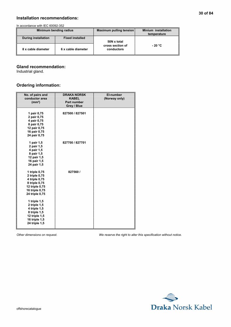
Installation recommendations:
In accordance with IEC 60092-352
Minimum bending radius Maximum pulling tension Minium installationtemperature
During installation Fixed installed50N x total
8 x cable diameter 6 x cable diametercross section of
conductors- 20 °C
Gland recommendation:Industrial gland.
Ordering information:
No. of pairs andconductor area
(mm²)
DRAKA NORSKKABEL
Part numberGrey / Blue
El-number(Norway only)
1 pair 0,75 827500 / 8275012 pair 0,754 pair 0,758 pair 0,75
12 pair 0,7516 pair 0,7524 pair 0,75
1 pair 1,5 827700 / 8277012 pair 1,54 pair 1,58 pair 1,5
12 pair 1,516 pair 1,524 pair 1,5
1 triple 0,75 827560 /2 triple 0,754 triple 0,758 triple 0,75
12 triple 0,7516 triple 0,7524 triple 0,75
1 triple 1,52 triple 1,54 triple 1,58 triple 1,5
12 triple 1,516 triple 1,524 triple 1,5
Other dimensions on request. We reserve the right to alter this specification without notice.

31 of 84
offshorecatalogue
Halogen-free fire resistant instrumentation cable BU(c) 250V
1 2 3 4 55
43
12
Fire resistant cablesCollective screen
BU (c) 250VMGT/EPR/EVA
Halogen-free
Maximum operatingconductor temperature : 85OCOperating voltage : 250V
Application
Fixed installation for instrumentation, communication,control, alarm, emergency and critical systems in safeareas.
Standards applied
IEC:60092-3 - Design guidelinesIEC:60332-3/A - Flame retardanceIEC:60331 - Fire resistanceIEC:60754-1,2 - Halogen-free propertiesIEC:61034-1,2 - Smoke density
CONSTRUCTIONCODE LETTER
Conductor Tinned, stranded copper. (1)
Insulation B Mica-tape (2) / EP-rubber. (3)
Twinning/screening
Colour coded cores twisted together and wrapped with polyestertape. Pairs / triples are laid up and collectively screened by copper(or aluminium) backed polyester tape with tinned copper drain wire.(4)
Sheath U Flame retardant halogen-free thermoset compound. (5)
Marking E.g; “meter” “year” DRAKA NORSK KABEL BU (c) 250V2 pair 0.75mm² FLEX-FLAME IEC 60331 IEC 60332-3/A “CE”
Colour Standard colour: Grey or blue.
Core identification:Black-Light BlueBlack-Light Blue-Brown
Pairs/triples are identified with numbered tape or by numbers printed directly on the insulated conductor.
.
32 of 84
offshorecatalogue
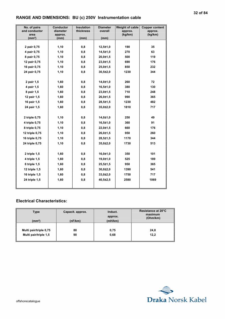
RANGE AND DIMENSIONS: BU (c) 250V Instrumentation cable
No. of pairsand conductor
area(mm²)
Conductordiameterapprox.
(mm)
Insulationthickness
(mm)
Diameteroverall
(mm)
Weight of cableapprox.(kg/km)
Copper contentapprox.(kg/km)
2 pair 0,75 1,10 0,8 12,5±1,0 190 35
4 pair 0,75 1,10 0,8 14,5±1,0 270 63
8 pair 0,75 1,10 0,8 20,0±1,5 500 119
12 pair 0,75 1,10 0,8 23,0±1,5 690 176
16 pair 0,75 1,10 0,8 25,0±1,5 850 232
24 pair 0,75 1,10 0,8 30,5±2,0 1230 344
2 pair 1,5 1,60 0,8 14,0±1,0 260 72
4 pair 1,5 1,60 0,8 16,5±1,0 380 130
8 pair 1,5 1,60 0,8 23,0±1,5 710 248
12 pair 1,5 1,60 0,8 26,0±1,5 990 365
16 pair 1,5 1,60 0,8 28,5±1,5 1230 482
24 pair 1,5 1,60 0,8 35,0±2,0 1810 717
2 triple 0,75 1,10 0,8 14,0±1,0 250 49
4 triple 0,75 1,10 0,8 16,5±1,0 360 91
8 triple 0,75 1,10 0,8 22,0±1,5 660 176
12 triple 0,75 1,10 0,8 26,0±1,5 950 260
16 triple 0,75 1,10 0,8 28,5±1,5 1170 344
24 triple 0,75 1,10 0,8 35,0±2,0 1730 513
2 triple 1,5 1,60 0,8 16,0±1,0 350 101
4 triple 1,5 1,60 0,8 19,0±1,0 525 189
8 triple 1,5 1,60 0,8 25,5±1,5 950 365
12 triple 1,5 1,60 0,8 30,0±2,0 1390 541
16 triple 1,5 1,60 0,8 33,0±2,0 1750 717
24 triple 1,5 1,60 0,8 40,5±2,5 2580 1069
Electrical Characteristics:
Type
(mm²)
Capacit. approx.
(nF/km)
Induct.
approx.
(mH/km)
Resistance at 20°Cmaximum (Ohm/km)
Multi pair/triple 0,75 80 0,75 24,8
Multi pair/triple 1,5 90 0,68 12,2
33 of 84
offshorecatalogue
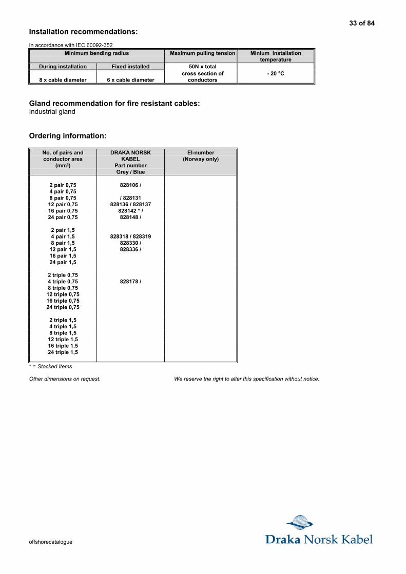
Installation recommendations:
In accordance with IEC 60092-352
Minimum bending radius Maximum pulling tension Minium installationtemperature
During installation Fixed installed 50N x total
8 x cable diameter 6 x cable diametercross section of
conductors- 20 °C
Gland recommendation for fire resistant cables:Industrial gland
Ordering information:
No. of pairs andconductor area
(mm²)
DRAKA NORSKKABEL
Part numberGrey / Blue
El-number(Norway only)
2 pair 0,75 828106 /4 pair 0,758 pair 0,75 / 828131
12 pair 0,75 828136 / 82813716 pair 0,75 828142 * /24 pair 0,75 828148 /
2 pair 1,54 pair 1,5 828318 / 8283198 pair 1,5 828330 /
12 pair 1,5 828336 /16 pair 1,524 pair 1,5
2 triple 0,754 triple 0,75 828178 /8 triple 0,75
12 triple 0,7516 triple 0,7524 triple 0,75
2 triple 1,54 triple 1,58 triple 1,5
12 triple 1,516 triple 1,524 triple 1,5
* = Stocked Items
Other dimensions on request. We reserve the right to alter this specification without notice.
34 of 84
offshorecatalogue
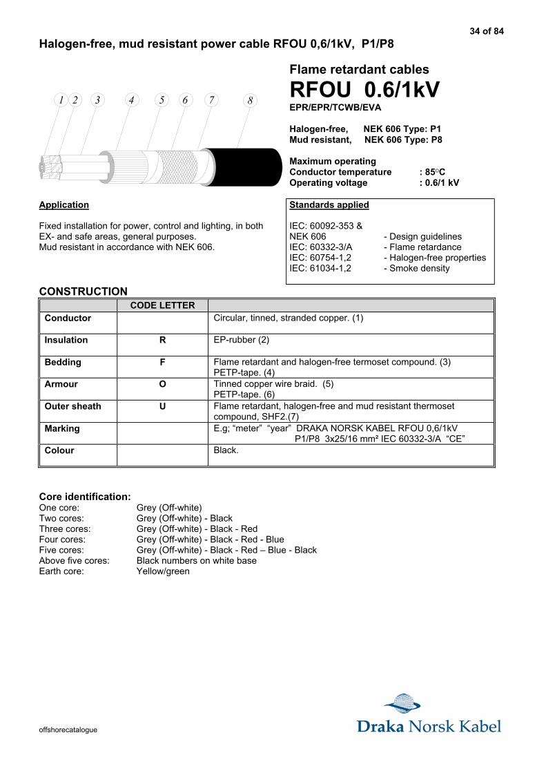
Halogen-free, mud resistant power cable RFOU 0,6/1kV, P1/P8
1 2 3 4 5 6 7 8
Flame retardant cables
RFOU 0.6/1kVEPR/EPR/TCWB/EVA
Halogen-free, NEK 606 Type: P1Mud resistant, NEK 606 Type: P8
Maximum operatingConductor temperature : 85OCOperating voltage : 0.6/1 kV
Application
Fixed installation for power, control and lighting, in bothEX- and safe areas, general purposes.Mud resistant in accordance with NEK 606.
Standards applied
IEC: 60092-353 &NEK 606 - Design guidelinesIEC: 60332-3/A - Flame retardanceIEC: 60754-1,2 - Halogen-free propertiesIEC: 61034-1,2 - Smoke density
CONSTRUCTIONCODE LETTER
Conductor Circular, tinned, stranded copper. (1)
Insulation R EP-rubber (2)
Bedding F Flame retardant and halogen-free termoset compound. (3)PETP-tape. (4)
Armour O Tinned copper wire braid. (5)PETP-tape. (6)
Outer sheath U Flame retardant, halogen-free and mud resistant thermosetcompound, SHF2.(7)
Marking E.g; “meter” “year” DRAKA NORSK KABEL RFOU 0,6/1kV P1/P8 3x25/16 mm² IEC 60332-3/A “CE”
Colour Black.
Core identification:One core: Grey (Off-white)Two cores: Grey (Off-white) - BlackThree cores: Grey (Off-white) - Black - RedFour cores: Grey (Off-white) - Black - Red - BlueFive cores: Grey (Off-white) - Black - Red – Blue - BlackAbove five cores: Black numbers on white baseEarth core: Yellow/green
35 of 84
offshorecatalogue
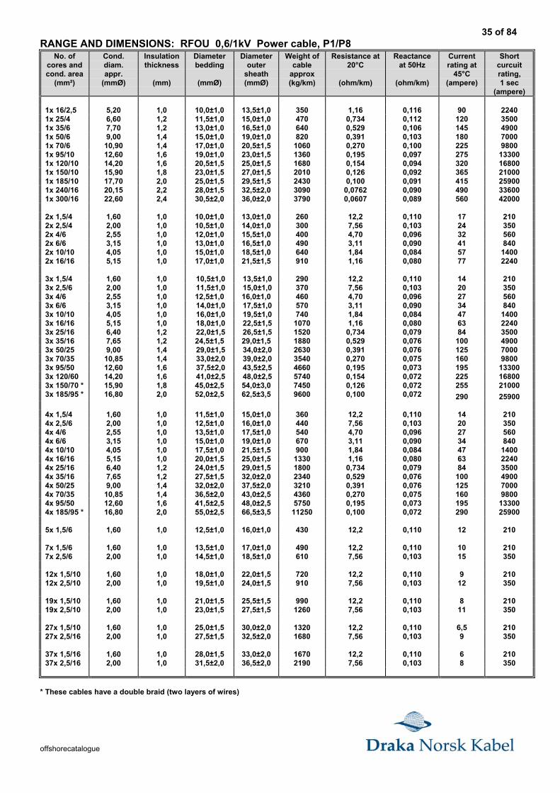
RANGE AND DIMENSIONS: RFOU 0,6/1kV Power cable, P1/P8No. of
cores andcond. area
(mm²)
Cond.diam.appr.
(mmØ)
Insulationthickness
(mm)
Diameterbedding
(mmØ)
Diameterouter
sheath(mmØ)
Weight ofcable
approx(kg/km)
Resistance at20°C
(ohm/km)
Reactanceat 50Hz
(ohm/km)
Currentrating at
45°C(ampere)
Shortcurcuitrating,1 sec
(ampere)
1x 16/2,5 5,20 1,0 10,0±1,0 13,5±1,0 350 1,16 0,116 90 22401x 25/4 6,60 1,2 11,5±1,0 15,0±1,0 470 0,734 0,112 120 35001x 35/6 7,70 1,2 13,0±1,0 16,5±1,0 640 0,529 0,106 145 49001x 50/6 9,00 1,4 15,0±1,0 19,0±1,0 820 0,391 0,103 180 70001x 70/6 10,90 1,4 17,0±1,0 20,5±1,5 1060 0,270 0,100 225 98001x 95/10 12,60 1,6 19,0±1,0 23,0±1,5 1360 0,195 0,097 275 133001x 120/10 14,20 1,6 20,5±1,5 25,0±1,5 1680 0,154 0,094 320 168001x 150/10 15,90 1,8 23,0±1,5 27,0±1,5 2010 0,126 0,092 365 210001x 185/10 17,70 2,0 25,0±1,5 29,5±1,5 2430 0,100 0,091 415 259001x 240/16 20,15 2,2 28,0±1,5 32,5±2,0 3090 0,0762 0,090 490 336001x 300/16 22,60 2,4 30,5±2,0 36,0±2,0 3790 0,0607 0,089 560 42000
2x 1,5/4 1,60 1,0 10,0±1,0 13,0±1,0 260 12,2 0,110 17 2102x 2,5/4 2,00 1,0 10,5±1,0 14,0±1,0 300 7,56 0,103 24 3502x 4/6 2,55 1,0 12,0±1,0 15,5±1,0 400 4,70 0,096 32 5602x 6/6 3,15 1,0 13,0±1,0 16,5±1,0 490 3,11 0,090 41 8402x 10/10 4,05 1,0 15,0±1,0 18,5±1,0 640 1,84 0,084 57 14002x 16/16 5,15 1,0 17,0±1,0 21,5±1,5 910 1,16 0,080 77 2240
3x 1,5/4 1,60 1,0 10,5±1,0 13,5±1,0 290 12,2 0,110 14 2103x 2,5/6 2,00 1,0 11,5±1,0 15,0±1,0 370 7,56 0,103 20 3503x 4/6 2,55 1,0 12,5±1,0 16,0±1,0 460 4,70 0,096 27 5603x 6/6 3,15 1,0 14,0±1,0 17,5±1,0 570 3,11 0,090 34 8403x 10/10 4,05 1,0 16,0±1,0 19,5±1,0 740 1,84 0,084 47 14003x 16/16 5,15 1,0 18,0±1,0 22,5±1,5 1070 1,16 0,080 63 22403x 25/16 6,40 1,2 22,0±1,5 26,5±1,5 1520 0,734 0,079 84 35003x 35/16 7,65 1,2 24,5±1,5 29,0±1,5 1880 0,529 0,076 100 49003x 50/25 9,00 1,4 29,0±1,5 34,0±2,0 2630 0,391 0,076 125 70003x 70/35 10,85 1,4 33,0±2,0 39,0±2,0 3540 0,270 0,075 160 98003x 95/50 12,60 1,6 37,5±2,0 43,5±2,5 4660 0,195 0,073 195 133003x 120/60 14,20 1,6 41,0±2,5 48,0±2,5 5740 0,154 0,072 225 168003x 150/70 * 15,90 1,8 45,0±2,5 54,0±3,0 7450 0,126 0,072 255 210003x 185/95 * 16,80 2,0 52,0±2,5 62,5±3,5 9600 0,100 0,072 290 25900
4x 1,5/4 1,60 1,0 11,5±1,0 15,0±1,0 360 12,2 0,110 14 2104x 2,5/6 2,00 1,0 12,5±1,0 16,0±1,0 440 7,56 0,103 20 3504x 4/6 2,55 1,0 13,5±1,0 17,5±1,0 540 4,70 0,096 27 5604x 6/6 3,15 1,0 15,0±1,0 19,0±1,0 670 3,11 0,090 34 8404x 10/10 4,05 1,0 17,5±1,0 21,5±1,5 900 1,84 0,084 47 14004x 16/16 5,15 1,0 20,0±1,5 25,0±1,5 1330 1,16 0,080 63 22404x 25/16 6,40 1,2 24,0±1,5 29,0±1,5 1800 0,734 0,079 84 35004x 35/16 7,65 1,2 27,5±1,5 32,0±2,0 2340 0,529 0,076 100 49004x 50/25 9,00 1,4 32,0±2,0 37,5±2,0 3210 0,391 0,076 125 70004x 70/35 10,85 1,4 36,5±2,0 43,0±2,5 4360 0,270 0,075 160 98004x 95/50 12,60 1,6 41,5±2,5 48,0±2,5 5750 0,195 0,073 195 133004x 185/95 * 16,80 2,0 55,0±2,5 66,5±3,5 11250 0,100 0,072 290 25900
5x 1,5/6 1,60 1,0 12,5±1,0 16,0±1,0 430 12,2 0,110 12 210
7x 1,5/6 1,60 1,0 13,5±1,0 17,0±1,0 490 12,2 0,110 10 2107x 2,5/6 2,00 1,0 14,5±1,0 18,5±1,0 610 7,56 0,103 15 350
12x 1,5/10 1,60 1,0 18,0±1,0 22,0±1,5 720 12,2 0,110 9 21012x 2,5/10 2,00 1,0 19,5±1,0 24,0±1,5 910 7,56 0,103 12 350
19x 1,5/10 1,60 1,0 21,0±1,5 25,5±1,5 990 12,2 0,110 8 21019x 2,5/10 2,00 1,0 23,0±1,5 27,5±1,5 1260 7,56 0,103 11 350
27x 1,5/10 1,60 1,0 25,0±1,5 30,0±2,0 1320 12,2 0,110 6,5 21027x 2,5/16 2,00 1,0 27,5±1,5 32,5±2,0 1680 7,56 0,103 9 350
37x 1,5/16 1,60 1,0 28,0±1,5 33,0±2,0 1670 12,2 0,110 6 21037x 2,5/16 2,00 1,0 31,5±2,0 36,5±2,0 2190 7,56 0,103 8 350
* These cables have a double braid (two layers of wires)
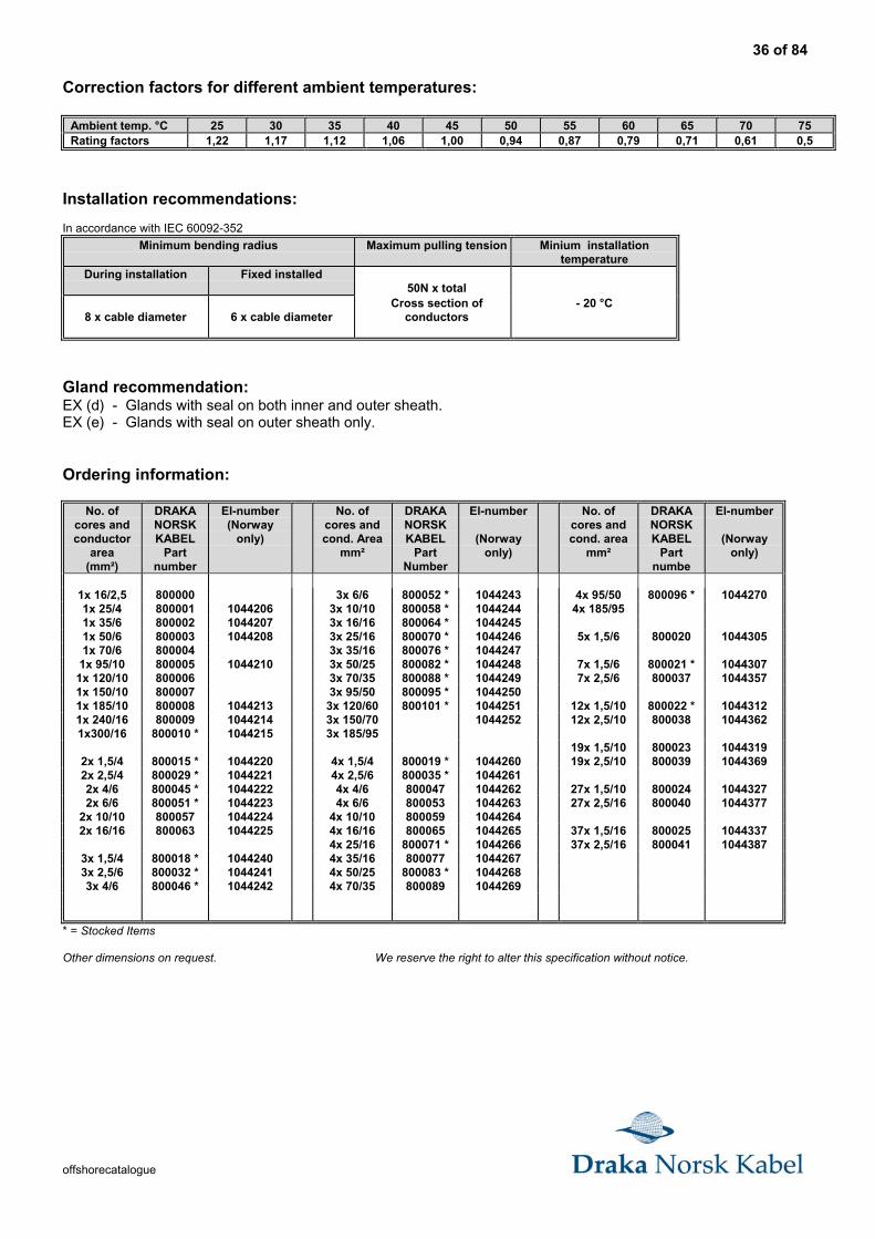
36 of 84
offshorecatalogue
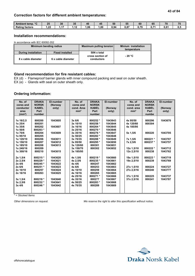
Correction factors for different ambient temperatures:
Ambient temp. °C 25 30 35 40 45 50 55 60 65 70 75Rating factors 1,22 1,17 1,12 1,06 1,00 0,94 0,87 0,79 0,71 0,61 0,5
Installation recommendations:
In accordance with IEC 60092-352
Minimum bending radius Maximum pulling tension Minium installationtemperature
During installation Fixed installed50N x total
8 x cable diameter 6 x cable diameterCross section of
conductors- 20 °C
Gland recommendation:EX (d) - Glands with seal on both inner and outer sheath.EX (e) - Glands with seal on outer sheath only.
Ordering information:
No. ofcores andconductor
area(mm²)
DRAKANORSKKABEL
Partnumber
El-number(Norway
only)
No. ofcores andcond. Area
mm²
DRAKANORSKKABEL
PartNumber
El-number
(Norwayonly)
No. ofcores andcond. area
mm²
DRAKANORSKKABEL
Partnumbe
El-number
(Norwayonly)
1x 16/2,5 800000 3x 6/6 800052 * 1044243 4x 95/50 800096 * 10442701x 25/4 800001 1044206 3x 10/10 800058 * 1044244 4x 185/951x 35/6 800002 1044207 3x 16/16 800064 * 10442451x 50/6 800003 1044208 3x 25/16 800070 * 1044246 5x 1,5/6 800020 10443051x 70/6 800004 3x 35/16 800076 * 1044247
1x 95/10 800005 1044210 3x 50/25 800082 * 1044248 7x 1,5/6 800021 * 10443071x 120/10 800006 3x 70/35 800088 * 1044249 7x 2,5/6 800037 10443571x 150/10 800007 3x 95/50 800095 * 10442501x 185/10 800008 1044213 3x 120/60 800101 * 1044251 12x 1,5/10 800022 * 10443121x 240/16 800009 1044214 3x 150/70 1044252 12x 2,5/10 800038 10443621x300/16 800010 * 1044215 3x 185/95
19x 1,5/10 800023 10443192x 1,5/4 800015 * 1044220 4x 1,5/4 800019 * 1044260 19x 2,5/10 800039 10443692x 2,5/4 800029 * 1044221 4x 2,5/6 800035 * 10442612x 4/6 800045 * 1044222 4x 4/6 800047 1044262 27x 1,5/10 800024 10443272x 6/6 800051 * 1044223 4x 6/6 800053 1044263 27x 2,5/16 800040 1044377
2x 10/10 800057 1044224 4x 10/10 800059 10442642x 16/16 800063 1044225 4x 16/16 800065 1044265 37x 1,5/16 800025 1044337
4x 25/16 800071 * 1044266 37x 2,5/16 800041 10443873x 1,5/4 800018 * 1044240 4x 35/16 800077 10442673x 2,5/6 800032 * 1044241 4x 50/25 800083 * 10442683x 4/6 800046 * 1044242 4x 70/35 800089 1044269
* = Stocked Items
Other dimensions on request. We reserve the right to alter this specification without notice.
37 of 84
offshorecatalogue
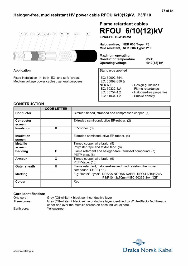
Halogen-free, mud resistant HV power cable RFOU 6/10(12)kV, P3/P10
1 2 3 4 5 8 96 117 10
Flame retardant cables
RFOU 6/10(12)kVEPR/EPR/TCWB/EVA
Halogen-free, NEK 606 Type: P3Mud resistant, NEK 606 Type: P10
Maximum operatingConductor temperature : 85OCOperating voltage : 6/10(12) kV
Application
Fixed installation in both EX- and safe areas.Medium voltage power cables , general purposes.
Standards applied
IEC: 60092-354,IEC: 60092-350 &NEK 606 - Design guidelinesIEC: 60332-3/A - Flame retardanceIEC: 60754-1,2 - Halogen-free propertiesIEC: 61034-1,2 - Smoke density
CONSTRUCTIONCODE LETTER
Conductor Circular, tinned, stranded and compressed copper. (1)
Conductorscreen
Extruded semi-conductive EP-rubber. (2)
Insulation R EP-rubber. (3)
Insulationscreen
Extruded semiconductive EP-rubber. (4)
Metallicscreen
Tinned copper wire braid. (5)Polyester tape and textile tape. (6)
Bedding F Flame retardant and halogen-free termoset compound. (7)PETP-tape. (8)
Armour O Tinned copper wire braid. (9)PETP-tape. (10)
Outer sheath U Flame retardant, halogen-free and mud resistant thermosetcompound, SHF2.( 11)
Marking E.g; “meter” “year” DRAKA NORSK KABEL RFOU 6/10(12)kV P3/P10 3x70mm² IEC 60332-3/A “CE”
Colour Red.
Core identification:One core: Grey (Off-white) + black semi-conductive layerThree cores: Grey (Off-white) + black semi-conductive layer identified by White-Black-Red threads
under and over the metallic screen on each individual core.Earth core: Yellow/green
38 of 84
offshorecatalogue
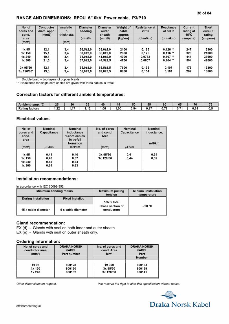
RANGE AND DIMENSIONS: RFOU 6/10kV Power cable, P3/P10
No. ofcores and
cond.area
(mm²)
Conductordiam. appr.
(mmØ)
Insulation
thickness
(mm)
Diameterbedding
(mmØ)
Diameterouter
sheath(mmØ)
Weight ofcable
approx(kg/km)
Resistance at20°C
(ohm/km)
Reactanceat 50Hz
(ohm/km)
Currentrating at
45°C(ampere)
Shortcurcuitrating
(ampere)
1x 95 12,1 3,4 26,5±2,0 33,0±2,0 2100 0,195 0,126 ** 247 133001x 150 15,1 3,4 30,0±2,0 36,0±2,0 2800 0,126 0,116 ** 328 210001x 240 19,1 3,4 34,0±2,0 41,0±2,0 4000 0,0762 0,107 ** 441 336001x 300 21,5 3,4 37,0±2,0 44,5±2,5 4750 0,0607 0,104 ** 504 42000
3x 95/50 12,1 3,4 55,0±3,0 63,5±3,5 7600 0,195 0,107 175 133003x 120/60* 13,6 3,4 58,0±3,0 69,0±3,5 8800 0,154 0,101 202 16800
* Double braid = two layers of copper braids** Reactance for single core cables are given with three cables in trefoil
Correction factors for different ambient temperatures:
Ambient temp. °C 25 30 35 40 45 50 55 60 65 70 75Rating factors 1,22 1,17 1,12 1,06 1,00 0,94 0,87 0,79 0,71 0,61 0,5
Electrical values
No. ofcores and
cond.area
(mm²)
NominalCapacitance
µF/km
Nominalinductance
1-core cablesin trefoil
formationmH/km
No. of coresand cond.
Area
(mm²)
NominalCapacitance
µF/km
Nominalinductance,
mH/km
1x 95 0,41 0,40 3x 95/50 0,41 0,341x 150 0,48 0,37 3x 120/60 0,44 0,321x 240 0,58 0,341x 300 0,64 0,33
Installation recommendations:
In accordance with IEC 60092-352
Minimum bending radius Maximum pullingtension
Minium installationtemperature
During installation Fixed installed50N x total
15 x cable diameter 9 x cable diameterCross section of
conductors- 20 °C
Gland recommendation:EX (d) - Glands with seal on both inner and outer sheath.EX (e) - Glands with seal on outer sheath only.
Ordering information:No. of cores andconductor area
(mm²)
DRAKA NORSKKABEL
Part number
No. of cores andcond. Area
Mm²
DRAKA NORSKKABEL
PartNumber
1x 95 800128 1x 300 8001331x 150 800130 3x 95/50 8001391x 240 800132 3x 120/60 800141
Other dimensions on request. We reserve the right to alter this specification without notice.
39 of 84
offshorecatalogue
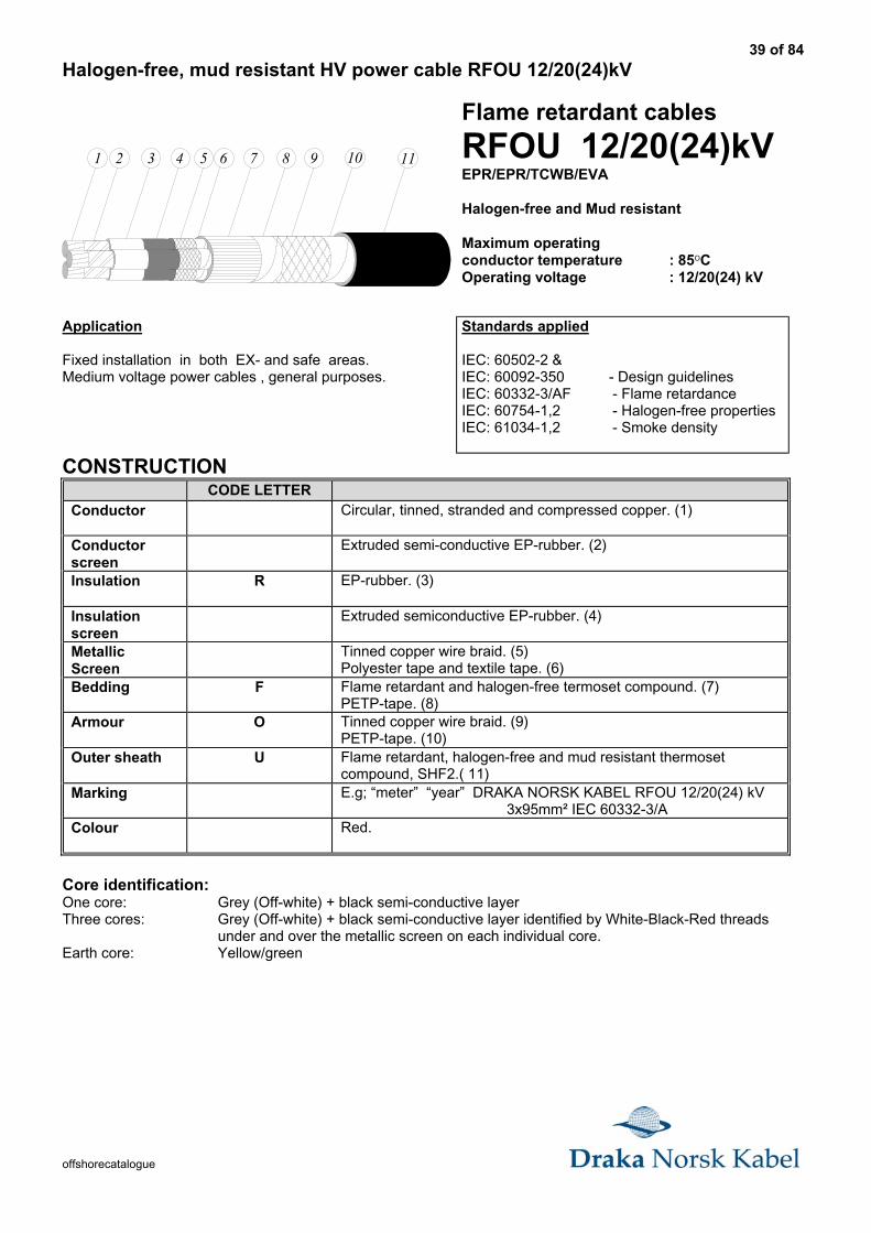
Halogen-free, mud resistant HV power cable RFOU 12/20(24)kV
1 2 3 4 5 8 96 117 10
Flame retardant cables
RFOU 12/20(24)kVEPR/EPR/TCWB/EVA
Halogen-free and Mud resistant
Maximum operatingconductor temperature : 85OCOperating voltage : 12/20(24) kV
Application
Fixed installation in both EX- and safe areas.Medium voltage power cables , general purposes.
Standards applied
IEC: 60502-2 &IEC: 60092-350 - Design guidelinesIEC: 60332-3/AF - Flame retardanceIEC: 60754-1,2 - Halogen-free propertiesIEC: 61034-1,2 - Smoke density
CONSTRUCTIONCODE LETTER
Conductor Circular, tinned, stranded and compressed copper. (1)
Conductorscreen
Extruded semi-conductive EP-rubber. (2)
Insulation R EP-rubber. (3)
Insulationscreen
Extruded semiconductive EP-rubber. (4)
MetallicScreen
Tinned copper wire braid. (5)Polyester tape and textile tape. (6)
Bedding F Flame retardant and halogen-free termoset compound. (7)PETP-tape. (8)
Armour O Tinned copper wire braid. (9)PETP-tape. (10)
Outer sheath U Flame retardant, halogen-free and mud resistant thermosetcompound, SHF2.( 11)
Marking E.g; “meter” “year” DRAKA NORSK KABEL RFOU 12/20(24) kV 3x95mm² IEC 60332-3/A
Colour Red.
Core identification:One core: Grey (Off-white) + black semi-conductive layerThree cores: Grey (Off-white) + black semi-conductive layer identified by White-Black-Red threads
under and over the metallic screen on each individual core.Earth core: Yellow/green
40 of 84
offshorecatalogue
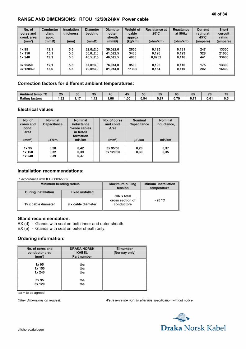
RANGE AND DIMENSIONS: RFOU 12/20(24)kV Power cable
No. ofcores andcond. area
(mm²)
Conductordiam.appr.
(mmØ)
Insulationthickness
(mm)
Diameterbedding
(mmØ)
Diameterouter
sheath(mmØ)
Weight ofcable
approx(kg/km)
Resistance at20°C
(ohm/km)
Reactanceat 50Hz
(ohm/km)
Currentrating at
45°C(ampere)
Shortcurcuitrating
(ampere)
1x 95 12,1 5,5 32,0±2,0 39,0±2,0 2650 0,195 0,131 247 133001x 150 15,1 5,5 35,0±2,0 41,5±2,5 3400 0,126 0,123 328 210001x 240 19,1 5,5 40,5±2,5 46,5±2,5 4800 0,0762 0,116 441 33600
3x 95/50 12,1 5,5 67,0±3,0 76,0±4,0 9500 0,195 0,116 175 133003x 120/60 13,6 5,5 70,0±3,0 81,0±4,0 11000 0,154 0,110 202 16800
Correction factors for different ambient temperatures:
Ambient temp. °C 25 30 35 40 45 50 55 60 65 70 75Rating factors 1,22 1,17 1,12 1,06 1,00 0,94 0,87 0,79 0,71 0,61 0,5
Electrical values
No. ofcores and
cond.area
(mm²)
NominalCapacitance
µF/km
Nominalinductance
1-core cablesin trefoil
formationmH/km
No. of coresand cond.
Area
(mm²)
NominalCapacitance
µF/km
Nominalinductance,
mH/km
1x 95 0,28 0,42 3x 95/50 0,28 0,371x 150 0,32 0,39 3x 120/60 0,30 0,351x 240 0,39 0,37
Installation recommendations:
In accordance with IEC 60092-352
Minimum bending radius Maximum pullingtension
Minium installationtemperature
During installation Fixed installed50N x total
15 x cable diameter 9 x cable diametercross section of
conductors- 20 °C
Gland recommendation:EX (d) - Glands with seal on both inner and outer sheath.EX (e) - Glands with seal on outer sheath only.
Ordering information:
No. of cores andconductor area
(mm²)
DRAKA NORSKKABEL
Part number
El-number(Norway only)
1x 95 tba1x 150 tba1x 240 tba
3x 95 tba3x 120 tba
tba = to be agreed
Other dimensions on request. We reserve the right to alter this specification without notice.
41 of 84
offshorecatalogue
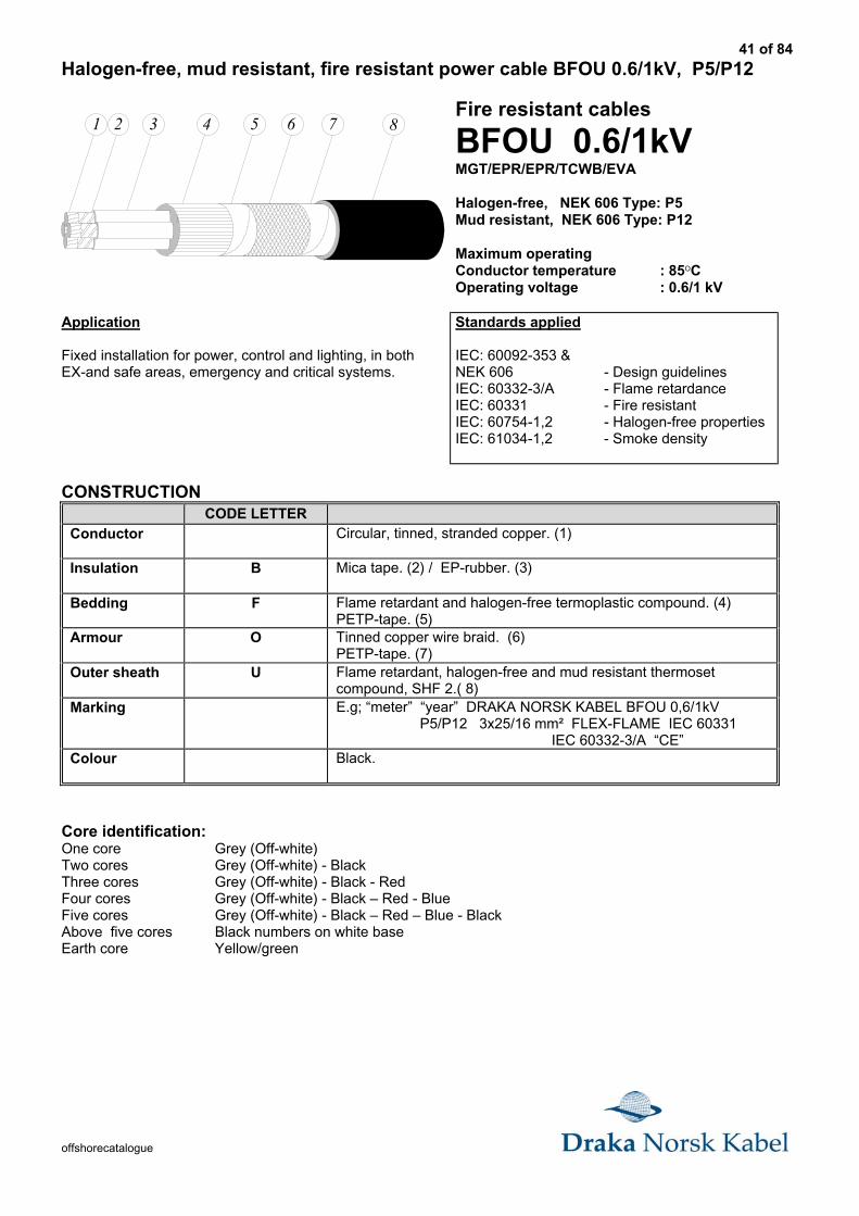
Halogen-free, mud resistant, fire resistant power cable BFOU 0.6/1kV, P5/P12
1 2 3 4 5 6 7 8Fire resistant cables
BFOU 0.6/1kVMGT/EPR/EPR/TCWB/EVA
Halogen-free, NEK 606 Type: P5Mud resistant, NEK 606 Type: P12
Maximum operatingConductor temperature : 85OCOperating voltage : 0.6/1 kV
Application
Fixed installation for power, control and lighting, in bothEX-and safe areas, emergency and critical systems.
Standards applied
IEC: 60092-353 &NEK 606 - Design guidelinesIEC: 60332-3/A - Flame retardanceIEC: 60331 - Fire resistantIEC: 60754-1,2 - Halogen-free propertiesIEC: 61034-1,2 - Smoke density
CONSTRUCTIONCODE LETTER
Conductor Circular, tinned, stranded copper. (1)
Insulation B Mica tape. (2) / EP-rubber. (3)
Bedding F Flame retardant and halogen-free termoplastic compound. (4)PETP-tape. (5)
Armour O Tinned copper wire braid. (6)PETP-tape. (7)
Outer sheath U Flame retardant, halogen-free and mud resistant thermosetcompound, SHF 2.( 8)
Marking E.g; “meter” “year” DRAKA NORSK KABEL BFOU 0,6/1kV P5/P12 3x25/16 mm² FLEX-FLAME IEC 60331 IEC 60332-3/A “CE”
Colour Black.
Core identification:One core Grey (Off-white)Two cores Grey (Off-white) - BlackThree cores Grey (Off-white) - Black - RedFour cores Grey (Off-white) - Black – Red - BlueFive cores Grey (Off-white) - Black – Red – Blue - BlackAbove five cores Black numbers on white baseEarth core Yellow/green
42 of 84
offshorecatalogue
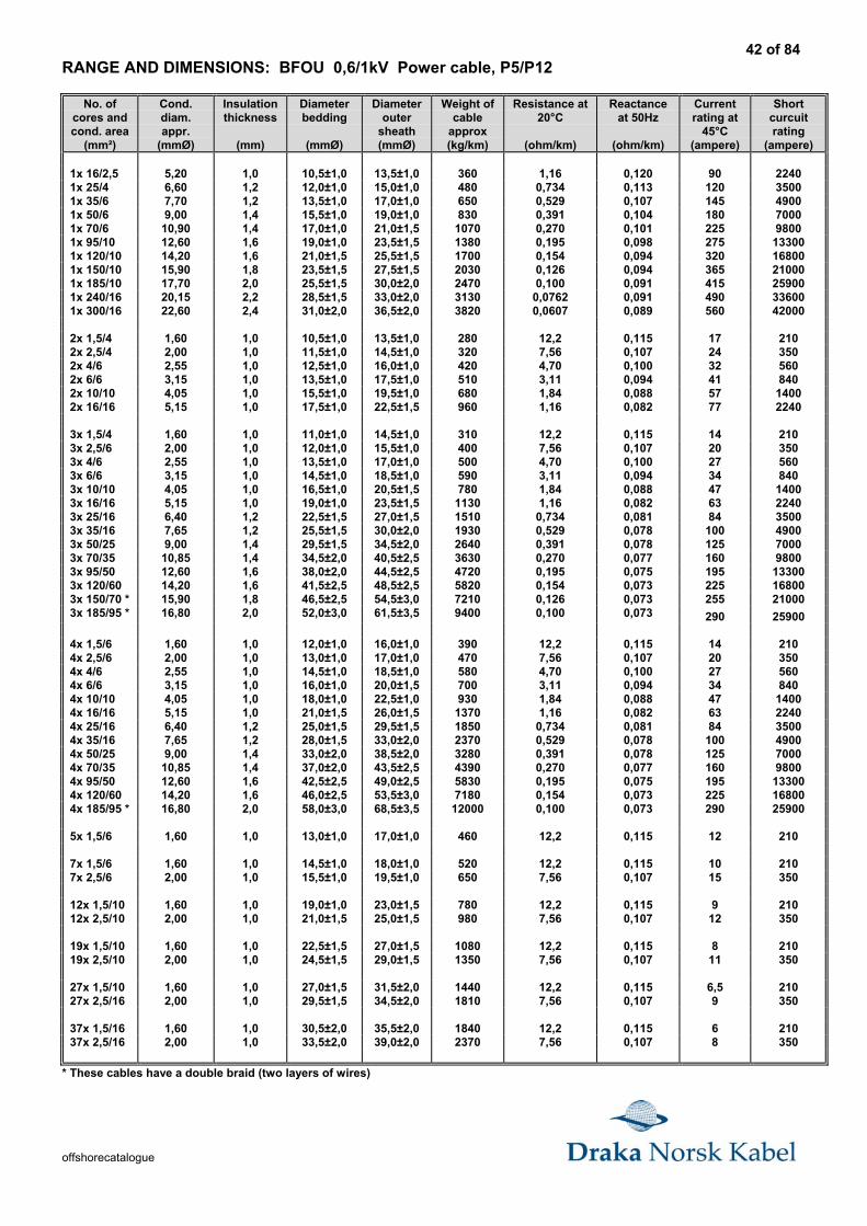
RANGE AND DIMENSIONS: BFOU 0,6/1kV Power cable, P5/P12
No. ofcores andcond. area
(mm²)
Cond.diam.appr.
(mmØ)
Insulationthickness
(mm)
Diameterbedding
(mmØ)
Diameterouter
sheath(mmØ)
Weight ofcable
approx(kg/km)
Resistance at20°C
(ohm/km)
Reactanceat 50Hz
(ohm/km)
Currentrating at
45°C(ampere)
Shortcurcuitrating
(ampere)
1x 16/2,5 5,20 1,0 10,5±1,0 13,5±1,0 360 1,16 0,120 90 22401x 25/4 6,60 1,2 12,0±1,0 15,0±1,0 480 0,734 0,113 120 35001x 35/6 7,70 1,2 13,5±1,0 17,0±1,0 650 0,529 0,107 145 49001x 50/6 9,00 1,4 15,5±1,0 19,0±1,0 830 0,391 0,104 180 70001x 70/6 10,90 1,4 17,0±1,0 21,0±1,5 1070 0,270 0,101 225 98001x 95/10 12,60 1,6 19,0±1,0 23,5±1,5 1380 0,195 0,098 275 133001x 120/10 14,20 1,6 21,0±1,5 25,5±1,5 1700 0,154 0,094 320 168001x 150/10 15,90 1,8 23,5±1,5 27,5±1,5 2030 0,126 0,094 365 210001x 185/10 17,70 2,0 25,5±1,5 30,0±2,0 2470 0,100 0,091 415 259001x 240/16 20,15 2,2 28,5±1,5 33,0±2,0 3130 0,0762 0,091 490 336001x 300/16 22,60 2,4 31,0±2,0 36,5±2,0 3820 0,0607 0,089 560 42000
2x 1,5/4 1,60 1,0 10,5±1,0 13,5±1,0 280 12,2 0,115 17 2102x 2,5/4 2,00 1,0 11,5±1,0 14,5±1,0 320 7,56 0,107 24 3502x 4/6 2,55 1,0 12,5±1,0 16,0±1,0 420 4,70 0,100 32 5602x 6/6 3,15 1,0 13,5±1,0 17,5±1,0 510 3,11 0,094 41 8402x 10/10 4,05 1,0 15,5±1,0 19,5±1,0 680 1,84 0,088 57 14002x 16/16 5,15 1,0 17,5±1,0 22,5±1,5 960 1,16 0,082 77 2240
3x 1,5/4 1,60 1,0 11,0±1,0 14,5±1,0 310 12,2 0,115 14 2103x 2,5/6 2,00 1,0 12,0±1,0 15,5±1,0 400 7,56 0,107 20 3503x 4/6 2,55 1,0 13,5±1,0 17,0±1,0 500 4,70 0,100 27 5603x 6/6 3,15 1,0 14,5±1,0 18,5±1,0 590 3,11 0,094 34 8403x 10/10 4,05 1,0 16,5±1,0 20,5±1,5 780 1,84 0,088 47 14003x 16/16 5,15 1,0 19,0±1,0 23,5±1,5 1130 1,16 0,082 63 22403x 25/16 6,40 1,2 22,5±1,5 27,0±1,5 1510 0,734 0,081 84 35003x 35/16 7,65 1,2 25,5±1,5 30,0±2,0 1930 0,529 0,078 100 49003x 50/25 9,00 1,4 29,5±1,5 34,5±2,0 2640 0,391 0,078 125 70003x 70/35 10,85 1,4 34,5±2,0 40,5±2,5 3630 0,270 0,077 160 98003x 95/50 12,60 1,6 38,0±2,0 44,5±2,5 4720 0,195 0,075 195 133003x 120/60 14,20 1,6 41,5±2,5 48,5±2,5 5820 0,154 0,073 225 168003x 150/70 * 15,90 1,8 46,5±2,5 54,5±3,0 7210 0,126 0,073 255 210003x 185/95 * 16,80 2,0 52,0±3,0 61,5±3,5 9400 0,100 0,073 290 25900
4x 1,5/6 1,60 1,0 12,0±1,0 16,0±1,0 390 12,2 0,115 14 2104x 2,5/6 2,00 1,0 13,0±1,0 17,0±1,0 470 7,56 0,107 20 3504x 4/6 2,55 1,0 14,5±1,0 18,5±1,0 580 4,70 0,100 27 5604x 6/6 3,15 1,0 16,0±1,0 20,0±1,5 700 3,11 0,094 34 8404x 10/10 4,05 1,0 18,0±1,0 22,5±1,0 930 1,84 0,088 47 14004x 16/16 5,15 1,0 21,0±1,5 26,0±1,5 1370 1,16 0,082 63 22404x 25/16 6,40 1,2 25,0±1,5 29,5±1,5 1850 0,734 0,081 84 35004x 35/16 7,65 1,2 28,0±1,5 33,0±2,0 2370 0,529 0,078 100 49004x 50/25 9,00 1,4 33,0±2,0 38,5±2,0 3280 0,391 0,078 125 70004x 70/35 10,85 1,4 37,0±2,0 43,5±2,5 4390 0,270 0,077 160 98004x 95/50 12,60 1,6 42,5±2,5 49,0±2,5 5830 0,195 0,075 195 133004x 120/60 14,20 1,6 46,0±2,5 53,5±3,0 7180 0,154 0,073 225 168004x 185/95 * 16,80 2,0 58,0±3,0 68,5±3,5 12000 0,100 0,073 290 25900
5x 1,5/6 1,60 1,0 13,0±1,0 17,0±1,0 460 12,2 0,115 12 210
7x 1,5/6 1,60 1,0 14,5±1,0 18,0±1,0 520 12,2 0,115 10 2107x 2,5/6 2,00 1,0 15,5±1,0 19,5±1,0 650 7,56 0,107 15 350
12x 1,5/10 1,60 1,0 19,0±1,0 23,0±1,5 780 12,2 0,115 9 21012x 2,5/10 2,00 1,0 21,0±1,5 25,0±1,5 980 7,56 0,107 12 350
19x 1,5/10 1,60 1,0 22,5±1,5 27,0±1,5 1080 12,2 0,115 8 21019x 2,5/10 2,00 1,0 24,5±1,5 29,0±1,5 1350 7,56 0,107 11 350
27x 1,5/10 1,60 1,0 27,0±1,5 31,5±2,0 1440 12,2 0,115 6,5 21027x 2,5/16 2,00 1,0 29,5±1,5 34,5±2,0 1810 7,56 0,107 9 350
37x 1,5/16 1,60 1,0 30,5±2,0 35,5±2,0 1840 12,2 0,115 6 21037x 2,5/16 2,00 1,0 33,5±2,0 39,0±2,0 2370 7,56 0,107 8 350
* These cables have a double braid (two layers of wires)
43 of 84
offshorecatalogue
Correction factors for different ambient temperatures:
Ambient temp. °C 25 30 35 40 45 50 55 60 65 70 75Rating factors 1,22 1,17 1,12 1,06 1,00 0,94 0,87 0,79 0,71 0,61 0,5
Installation recommendations:
In accordance with IEC 60092-352
Minimum bending radius Maximum pulling tension Minium installationtemperature
During installation Fixed installed 50N x total
8 x cable diameter 6 x cable diametercross section of
conductors - 20 °C
Gland recommendation for fire resistant cables:EX (d) - Flameproof barrier glands with inner compound packing and seal on outer sheath.EX (e) - Glands with seal on outer sheath only.
Ordering information:
No. ofcores andconductor
area(mm²)
DRAKANORSKKABEL
Partnumber
El-number(Norway
only)
No. ofcores andcond. Area
mm²
DRAKANORSKKABEL
Partnumber
El-number
(Norwayonly)
No. ofcores andcond. area
mm²
DRAKANORSKKABEL
Partnumbe
El-number
(Norwayonly)
1x 16/2,5 800200 1043605 3x 6/6 800252 * 1043643 4x 95/50 800296 10436701x 25/4 800201 3x 10/10 800258 * 1043644 4x 120/60 8003041x 35/6 800202 1043607 3x 16/16 800264 * 1043645 4x 185/951x 50/6 800203 * 3x 25/16 800270 * 10436461x 70/6 800204 1043609 3x 35/16 800276 * 1043647 5x 1,5/6 800220 10437051x 95/10 800205 3x 50/25 800282 * 10436481x 120/10 800206 1043611 3x 70/35 800288 * 1043649 7x 1,5/6 800221 * 10437071x 150/10 800207 1043612 3x 95/50 800295 * 1043650 7x 2,5/6 800237 * 10437571x 185/10 800208 1043613 3x 120/60 800301 10436511x 240/16 800209 3x 150/70 800302 1043652 12x 1,5/10 800222 * 10437121x 300/16 800210 1043615 3x 185/95 12x 2,5/10 800238 1043762
2x 1,5/4 800215 * 1043620 4x 1,5/6 800219 * 1043660 19x 1,5/10 800223 * 10437192x 2,5/4 800229 * 1043621 4x 2,5/6 800235 * 1043661 19x 2,5/10 800239 10437692x 4/6 800245 * 1043622 4x 4/6 800247 10436622x 6/6 800251 * 1043623 4x 6/6 800253 1043663 27x 1,5/10 800224 10437272x 10/10 800257 1043624 4x 10/10 800259 1043664 27x 2,5/16 800240 10437772x 16/16 800263 1043625 4x 16/16 800265 1043665
4x 25/16 800271 * 1043666 37x 1,5/16 800225 10437373x 1,5/4 800218 * 1043640 4x 35/16 800277 1043667 37x 2,5/16 800241 10437873x 2,5/6 800232 * 1043641 4x 50/25 800283 * 10436683x 4/6 800246 * 1043642 4x 70/35 800289 1043669
* = Stocked Items
Other dimensions on request. We reserve the right to alter this specification without notice.
44 of 84
offshorecatalogue
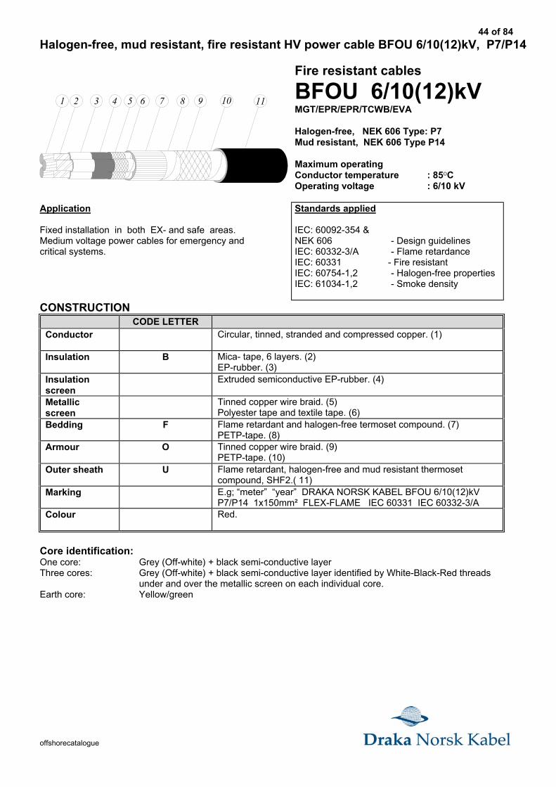
Halogen-free, mud resistant, fire resistant HV power cable BFOU 6/10(12)kV, P7/P14
1 2 3 4 5 8 96 117 10
Fire resistant cables
BFOU 6/10(12)kVMGT/EPR/EPR/TCWB/EVA
Halogen-free, NEK 606 Type: P7Mud resistant, NEK 606 Type P14
Maximum operatingConductor temperature : 85OCOperating voltage : 6/10 kV
Application
Fixed installation in both EX- and safe areas.Medium voltage power cables for emergency andcritical systems.
Standards applied
IEC: 60092-354 &NEK 606 - Design guidelinesIEC: 60332-3/A - Flame retardanceIEC: 60331 - Fire resistantIEC: 60754-1,2 - Halogen-free propertiesIEC: 61034-1,2 - Smoke density
CONSTRUCTIONCODE LETTER
Conductor Circular, tinned, stranded and compressed copper. (1)
Insulation B Mica- tape, 6 layers. (2)EP-rubber. (3)
Insulationscreen
Extruded semiconductive EP-rubber. (4)
Metallicscreen
Tinned copper wire braid. (5)Polyester tape and textile tape. (6)
Bedding F Flame retardant and halogen-free termoset compound. (7)PETP-tape. (8)
Armour O Tinned copper wire braid. (9)PETP-tape. (10)
Outer sheath U Flame retardant, halogen-free and mud resistant thermosetcompound, SHF2.( 11)
Marking E.g; “meter” “year” DRAKA NORSK KABEL BFOU 6/10(12)kVP7/P14 1x150mm² FLEX-FLAME IEC 60331 IEC 60332-3/A
Colour Red.
Core identification:One core: Grey (Off-white) + black semi-conductive layerThree cores: Grey (Off-white) + black semi-conductive layer identified by White-Black-Red threads
under and over the metallic screen on each individual core.Earth core: Yellow/green
45 of 84
offshorecatalogue
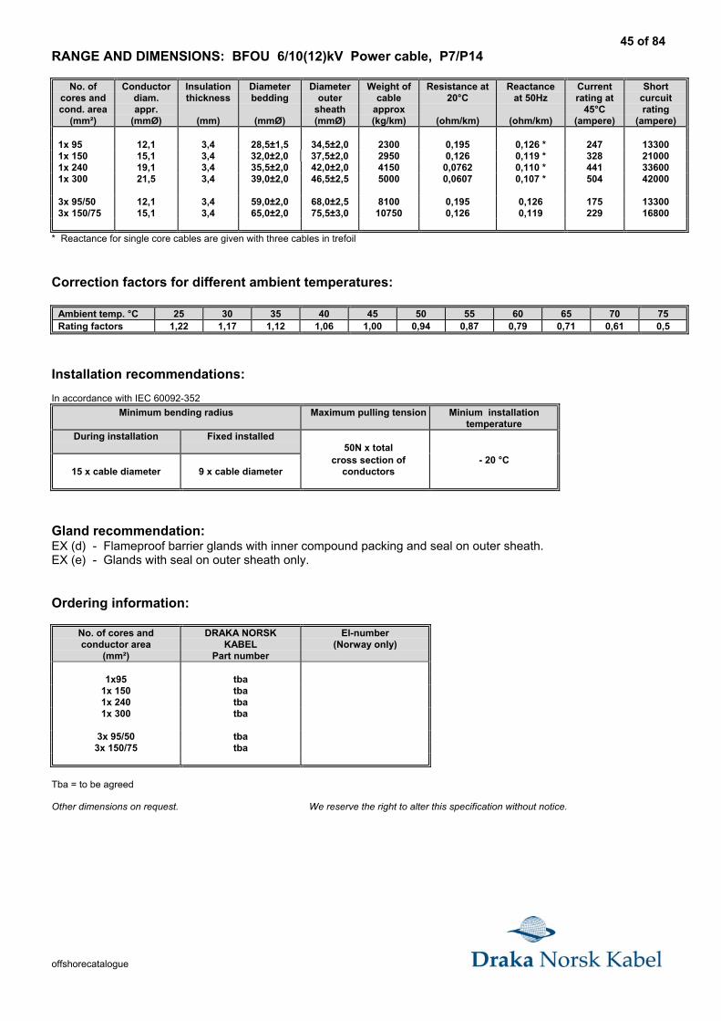
RANGE AND DIMENSIONS: BFOU 6/10(12)kV Power cable, P7/P14
No. ofcores andcond. area
(mm²)
Conductordiam.appr.
(mmØ)
Insulationthickness
(mm)
Diameterbedding
(mmØ)
Diameterouter
sheath(mmØ)
Weight ofcable
approx(kg/km)
Resistance at20°C
(ohm/km)
Reactanceat 50Hz
(ohm/km)
Currentrating at
45°C(ampere)
Shortcurcuitrating
(ampere)
1x 95 12,1 3,4 28,5±1,5 34,5±2,0 2300 0,195 0,126 * 247 133001x 150 15,1 3,4 32,0±2,0 37,5±2,0 2950 0,126 0,119 * 328 210001x 240 19,1 3,4 35,5±2,0 42,0±2,0 4150 0,0762 0,110 * 441 336001x 300 21,5 3,4 39,0±2,0 46,5±2,5 5000 0,0607 0,107 * 504 42000
3x 95/50 12,1 3,4 59,0±2,0 68,0±2,5 8100 0,195 0,126 175 133003x 150/75 15,1 3,4 65,0±2,0 75,5±3,0 10750 0,126 0,119 229 16800
* Reactance for single core cables are given with three cables in trefoil
Correction factors for different ambient temperatures:
Ambient temp. °C 25 30 35 40 45 50 55 60 65 70 75Rating factors 1,22 1,17 1,12 1,06 1,00 0,94 0,87 0,79 0,71 0,61 0,5
Installation recommendations:
In accordance with IEC 60092-352
Minimum bending radius Maximum pulling tension Minium installationtemperature
During installation Fixed installed50N x total
15 x cable diameter 9 x cable diametercross section of
conductors- 20 °C
Gland recommendation:EX (d) - Flameproof barrier glands with inner compound packing and seal on outer sheath.EX (e) - Glands with seal on outer sheath only.
Ordering information:
No. of cores andconductor area
(mm²)
DRAKA NORSKKABEL
Part number
El-number(Norway only)
1x95 tba1x 150 tba1x 240 tba1x 300 tba
3x 95/50 tba3x 150/75 tba
Tba = to be agreed
Other dimensions on request. We reserve the right to alter this specification without notice.
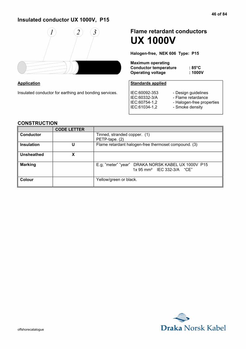
46 of 84
offshorecatalogue
Insulated conductor UX 1000V, P15
1 2 3 Flame retardant conductors
UX 1000VHalogen-free, NEK 606 Type: P15
Maximum operatingConductor temperature : 85°COperating voltage : 1000V
Application
Insulated conductor for earthing and bonding services.
Standards applied
IEC:60092-353 - Design guidelinesIEC:60332-3/A - Flame retardanceIEC:60754-1,2 - Halogen-free propertiesIEC:61034-1,2 - Smoke density
CONSTRUCTIONCODE LETTER
Conductor Tinned, stranded copper. (1)PETP-tape. (2)
Insulation U Flame retardant halogen-free thermoset compound. (3)
Unsheathed X
Marking E.g; ”meter” ”year” DRAKA NORSK KABEL UX 1000V P15 1x 95 mm² IEC 332-3/A “CE”
Colour Yellow/green or black.
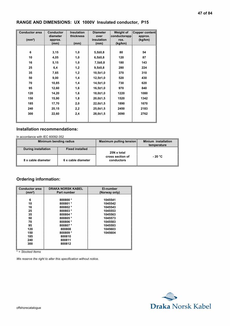
47 of 84
offshorecatalogue
RANGE AND DIMENSIONS: UX 1000V Insulated conductor, P15
Conductor area
(mm²)
Conductordiameterapprox.
(mm)
Insulationthickness
(mm)
Diameterover
insulation(mm)
Weight ofconductorapp
rox.(kg/km)
Copper contentapprox.(kg/km)
6 3,15 1,0 5,5±0,8 80 54
10 4,05 1,0 6,5±0,8 120 87
16 5,15 1,0 7,5±0,8 180 143
25 6,4 1,2 9,5±0,8 280 224
35 7,65 1,2 10,5±1,0 370 310
50 9,00 1,4 12,5±1,0 520 430
70 10,85 1,4 14,5±1,0 730 620
95 12,60 1,6 16,5±1,0 970 840
120 14,20 1,6 18,0±1,0 1220 1080
150 15,90 1,8 20,0±1,5 1520 1342
185 17,70 2,0 22,0±1,5 1890 1670
240 20,15 2,2 25,0±1,5 2450 2183
300 22,60 2,4 28,0±1,5 3090 2762
Installation recommendations:
In accordance with IEC 60092-352
Minimum bending radius Maximum pulling tension Minium installationtemperature
During installation Fixed installed25N x total
8 x cable diameter 6 x cable diametercross section of
conductors- 20 °C
Ordering information:
Conductor area(mm²)
DRAKA NORSK KABELPart number
El-number(Norway only)
6 800800 * 104554110 800801 * 104554216 800802 * 104554325 800803 * 104555335 800804 * 104556350 800805 * 104557370 800806 * 104558395 800807 * 1045593
120 800808 1045603150 800809 * 1045604185 800810240 800811300 800812
* = Stocked Items
We reserve the right to alter this specification without notice.
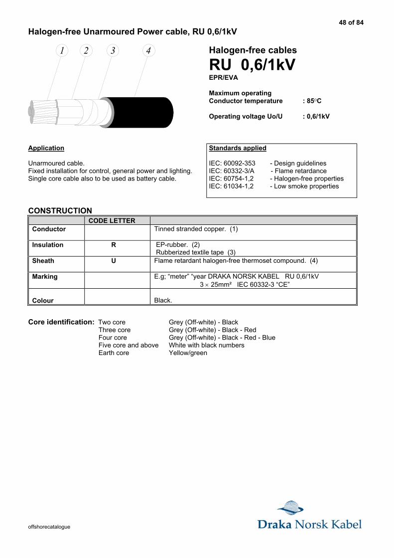
48 of 84
offshorecatalogue
Halogen-free Unarmoured Power cable, RU 0,6/1kV
1 2 3 4 Halogen-free cables
RU 0,6/1kVEPR/EVA
Maximum operatingConductor temperature : 85OC
Operating voltage Uo/U : 0,6/1kV
Application
Unarmoured cable.Fixed installation for control, general power and lighting.Single core cable also to be used as battery cable.
Standards applied
IEC: 60092-353 - Design guidelinesIEC: 60332-3/A - Flame retardanceIEC: 60754-1,2 - Halogen-free propertiesIEC: 61034-1,2 - Low smoke properties
CONSTRUCTIONCODE LETTER
Conductor Tinned stranded copper. (1)
Insulation R EP-rubber. (2) Rubberized textile tape (3)
Sheath U Flame retardant halogen-free thermoset compound. (4)
Marking E.g; “meter” “year DRAKA NORSK KABEL RU 0,6/1kV 3 × 25mm² IEC 60332-3 “CE”
Colour Black.
Core identification: Two core Grey (Off-white) - BlackThree core Grey (Off-white) - Black - RedFour core Grey (Off-white) - Black - Red - BlueFive core and above White with black numbersEarth core Yellow/green
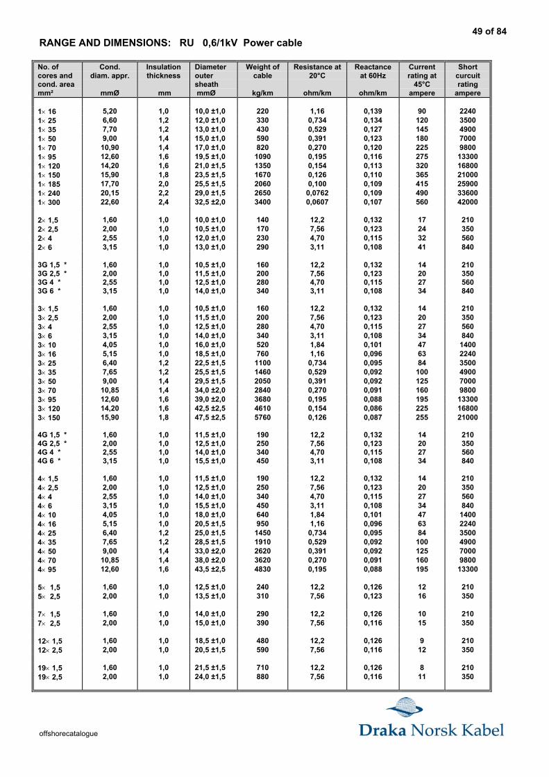
49 of 84
offshorecatalogue
RANGE AND DIMENSIONS: RU 0,6/1kV Power cable
No. ofcores andcond. areamm²
Cond.diam. appr.
mmØ
Insulationthickness
mm
Diameteroutersheath mmØ
Weight ofcable
kg/km
Resistance at20°C
ohm/km
Reactanceat 60Hz
ohm/km
Currentrating at
45°Campere
Shortcurcuitrating
ampere
1× 16 5,20 1,0 10,0 ±1,0 220 1,16 0,139 90 22401× 25 6,60 1,2 12,0 ±1,0 330 0,734 0,134 120 35001× 35 7,70 1,2 13,0 ±1,0 430 0,529 0,127 145 49001× 50 9,00 1,4 15,0 ±1,0 590 0,391 0,123 180 70001× 70 10,90 1,4 17,0 ±1,0 820 0,270 0,120 225 98001× 95 12,60 1,6 19,5 ±1,0 1090 0,195 0,116 275 133001× 120 14,20 1,6 21,0 ±1,5 1350 0,154 0,113 320 168001× 150 15,90 1,8 23,5 ±1,5 1670 0,126 0,110 365 210001× 185 17,70 2,0 25,5 ±1,5 2060 0,100 0,109 415 259001× 240 20,15 2,2 29,0 ±1,5 2650 0,0762 0,109 490 336001× 300 22,60 2,4 32,5 ±2,0 3400 0,0607 0,107 560 42000
2× 1,5 1,60 1,0 10,0 ±1,0 140 12,2 0,132 17 2102× 2,5 2,00 1,0 10,5 ±1,0 170 7,56 0,123 24 3502× 4 2,55 1,0 12,0 ±1,0 230 4,70 0,115 32 5602× 6 3,15 1,0 13,0 ±1,0 290 3,11 0,108 41 840
3G 1,5 * 1,60 1,0 10,5 ±1,0 160 12,2 0,132 14 2103G 2,5 * 2,00 1,0 11,5 ±1,0 200 7,56 0,123 20 3503G 4 * 2,55 1,0 12,5 ±1,0 280 4,70 0,115 27 5603G 6 * 3,15 1,0 14,0 ±1,0 340 3,11 0,108 34 840
3× 1,5 1,60 1,0 10,5 ±1,0 160 12,2 0,132 14 2103× 2,5 2,00 1,0 11,5 ±1,0 200 7,56 0,123 20 3503× 4 2,55 1,0 12,5 ±1,0 280 4,70 0,115 27 5603× 6 3,15 1,0 14,0 ±1,0 340 3,11 0,108 34 8403× 10 4,05 1,0 16,0 ±1,0 520 1,84 0,101 47 14003× 16 5,15 1,0 18,5 ±1,0 760 1,16 0,096 63 22403× 25 6,40 1,2 22,5 ±1,5 1100 0,734 0,095 84 35003× 35 7,65 1,2 25,5 ±1,5 1460 0,529 0,092 100 49003× 50 9,00 1,4 29,5 ±1,5 2050 0,391 0,092 125 70003× 70 10,85 1,4 34,0 ±2,0 2840 0,270 0,091 160 98003× 95 12,60 1,6 39,0 ±2,0 3680 0,195 0,088 195 133003× 120 14,20 1,6 42,5 ±2,5 4610 0,154 0,086 225 168003× 150 15,90 1,8 47,5 ±2,5 5760 0,126 0,087 255 21000
4G 1,5 * 1,60 1,0 11,5 ±1,0 190 12,2 0,132 14 2104G 2,5 * 2,00 1,0 12,5 ±1,0 250 7,56 0,123 20 3504G 4 * 2,55 1,0 14,0 ±1,0 340 4,70 0,115 27 5604G 6 * 3,15 1,0 15,5 ±1,0 450 3,11 0,108 34 840
4× 1,5 1,60 1,0 11,5 ±1,0 190 12,2 0,132 14 2104× 2,5 2,00 1,0 12,5 ±1,0 250 7,56 0,123 20 3504× 4 2,55 1,0 14,0 ±1,0 340 4,70 0,115 27 5604× 6 3,15 1,0 15,5 ±1,0 450 3,11 0,108 34 8404× 10 4,05 1,0 18,0 ±1,0 640 1,84 0,101 47 14004× 16 5,15 1,0 20,5 ±1,5 950 1,16 0,096 63 22404× 25 6,40 1,2 25,0 ±1,5 1450 0,734 0,095 84 35004× 35 7,65 1,2 28,5 ±1,5 1910 0,529 0,092 100 49004× 50 9,00 1,4 33,0 ±2,0 2620 0,391 0,092 125 70004× 70 10,85 1,4 38,0 ±2,0 3620 0,270 0,091 160 98004× 95 12,60 1,6 43,5 ±2,5 4830 0,195 0,088 195 13300
5× 1,5 1,60 1,0 12,5 ±1,0 240 12,2 0,126 12 2105× 2,5 2,00 1,0 13,5 ±1,0 310 7,56 0,123 16 350
7× 1,5 1,60 1,0 14,0 ±1,0 290 12,2 0,126 10 2107× 2,5 2,00 1,0 15,0 ±1,0 390 7,56 0,116 15 350
12× 1,5 1,60 1,0 18,5 ±1,0 480 12,2 0,126 9 21012× 2,5 2,00 1,0 20,5 ±1,5 590 7,56 0,116 12 350
19× 1,5 1,60 1,0 21,5 ±1,5 710 12,2 0,126 8 21019× 2,5 2,00 1,0 24,0 ±1,5 880 7,56 0,116 11 350
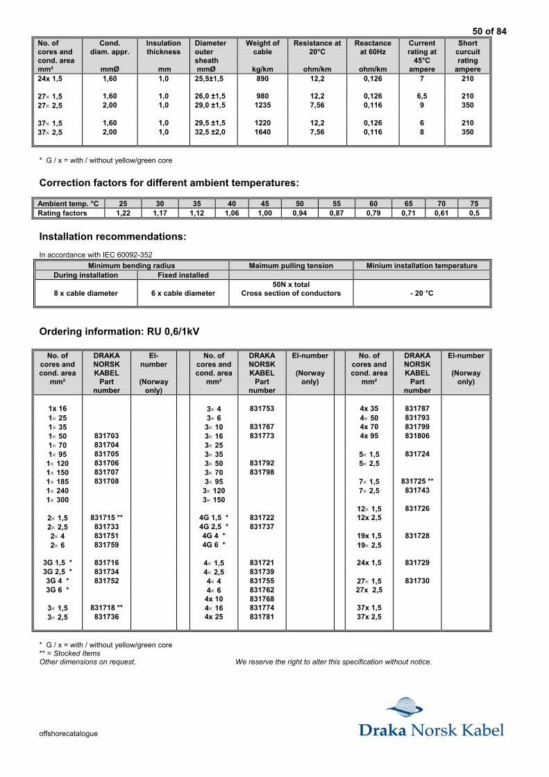
50 of 84
offshorecatalogue
No. ofcores andcond. areamm²
Cond.diam. appr.
mmØ
Insulationthickness
mm
Diameteroutersheath mmØ
Weight ofcable
kg/km
Resistance at20°C
ohm/km
Reactanceat 60Hz
ohm/km
Currentrating at
45°Campere
Shortcurcuitrating
ampere24x 1,5 1,60 1,0 25,5±1,5 890 12,2 0,126 7 210
27× 1,5 1,60 1,0 26,0 ±1,5 980 12,2 0,126 6,5 21027× 2,5 2,00 1,0 29,0 ±1,5 1235 7,56 0,116 9 350
37× 1,5 1,60 1,0 29,5 ±1,5 1220 12,2 0,126 6 21037× 2,5 2,00 1,0 32,5 ±2,0 1640 7,56 0,116 8 350
* G / x = with / without yellow/green core
Correction factors for different ambient temperatures:
Ambient temp. °C 25 30 35 40 45 50 55 60 65 70 75Rating factors 1,22 1,17 1,12 1,06 1,00 0,94 0,87 0,79 0,71 0,61 0,5
Installation recommendations:
In accordance with IEC 60092-352
Minimum bending radius Maimum pulling tension Minium installation temperatureDuring installation Fixed installed
8 x cable diameter 6 x cable diameter50N x total
Cross section of conductors - 20 °C
Ordering information: RU 0,6/1kV
No. ofcores andcond. area
mm²
DRAKANORSKKABEL
Partnumber
El-number
(Norwayonly)
No. ofcores andcond. area
mm²
DRAKANORSKKABEL
Partnumber
El-number
(Norwayonly)
No. ofcores andcond. area
mm²
DRAKANORSKKABEL
Partnumber
El-number
(Norwayonly)
1x 16 3× 4 831753 4x 35 8317871× 25 3× 6 4× 50 8317931× 35 3× 10 831767 4x 70 8317991× 50 831703 3× 16 831773 4x 95 8318061× 70 831704 3× 251× 95 831705 3× 35 5× 1,5 831724
1× 120 831706 3× 50 831792 5× 2,51× 150 831707 3× 70 8317981× 185 831708 3× 95 7× 1,5 831725 **1× 240 3× 120 7× 2,5 8317431× 300 3× 150
12× 1,5 8317262× 1,5 831715 ** 4G 1,5 * 831722 12x 2,52× 2,5 831733 4G 2,5 * 8317372× 4 831751 4G 4 * 19x 1,5 8317282× 6 831759 4G 6 * 19× 2,5
3G 1,5 * 831716 4× 1,5 831721 24x 1,5 8317293G 2,5 * 831734 4× 2,5 8317393G 4 * 831752 4× 4 831755 27× 1,5 8317303G 6 * 4× 6 831762 27x 2,5
4x 10 8317683× 1,5 831718 ** 4× 16 831774 37x 1,53× 2,5 831736 4x 25 831781 37x 2,5
* G / x = with / without yellow/green core** = Stocked ItemsOther dimensions on request. We reserve the right to alter this specification without notice.
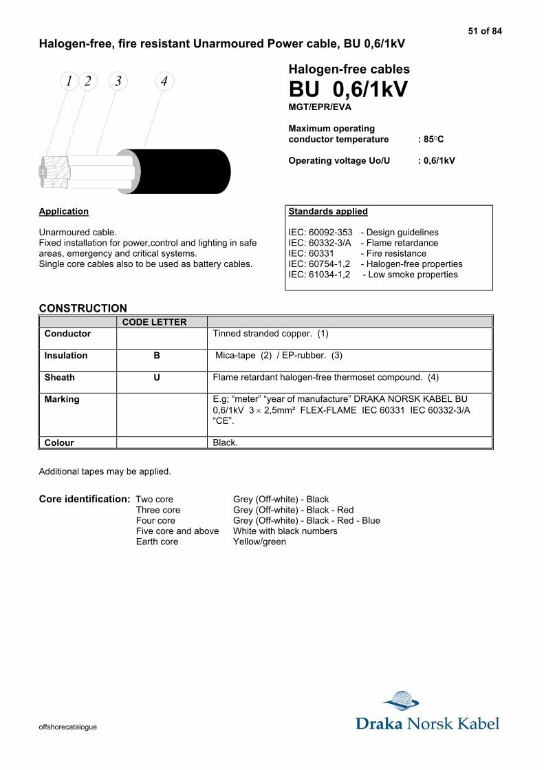
51 of 84
offshorecatalogue
Halogen-free, fire resistant Unarmoured Power cable, BU 0,6/1kV
1 2 3 4Halogen-free cables
BU 0,6/1kVMGT/EPR/EVA
Maximum operatingconductor temperature : 85OC
Operating voltage Uo/U : 0,6/1kV
Application
Unarmoured cable.Fixed installation for power,control and lighting in safeareas, emergency and critical systems.Single core cables also to be used as battery cables.
Standards applied
IEC: 60092-353 - Design guidelinesIEC: 60332-3/A - Flame retardanceIEC: 60331 - Fire resistanceIEC: 60754-1,2 - Halogen-free propertiesIEC: 61034-1,2 - Low smoke properties
CONSTRUCTIONCODE LETTER
Conductor Tinned stranded copper. (1)
Insulation B Mica-tape (2) / EP-rubber. (3)
Sheath U Flame retardant halogen-free thermoset compound. (4)
Marking E.g; “meter” “year of manufacture” DRAKA NORSK KABEL BU0,6/1kV 3 × 2,5mm² FLEX-FLAME IEC 60331 IEC 60332-3/A“CE”.
Colour Black.
Additional tapes may be applied.
Core identification: Two core Grey (Off-white) - BlackThree core Grey (Off-white) - Black - RedFour core Grey (Off-white) - Black - Red - BlueFive core and above White with black numbersEarth core Yellow/green
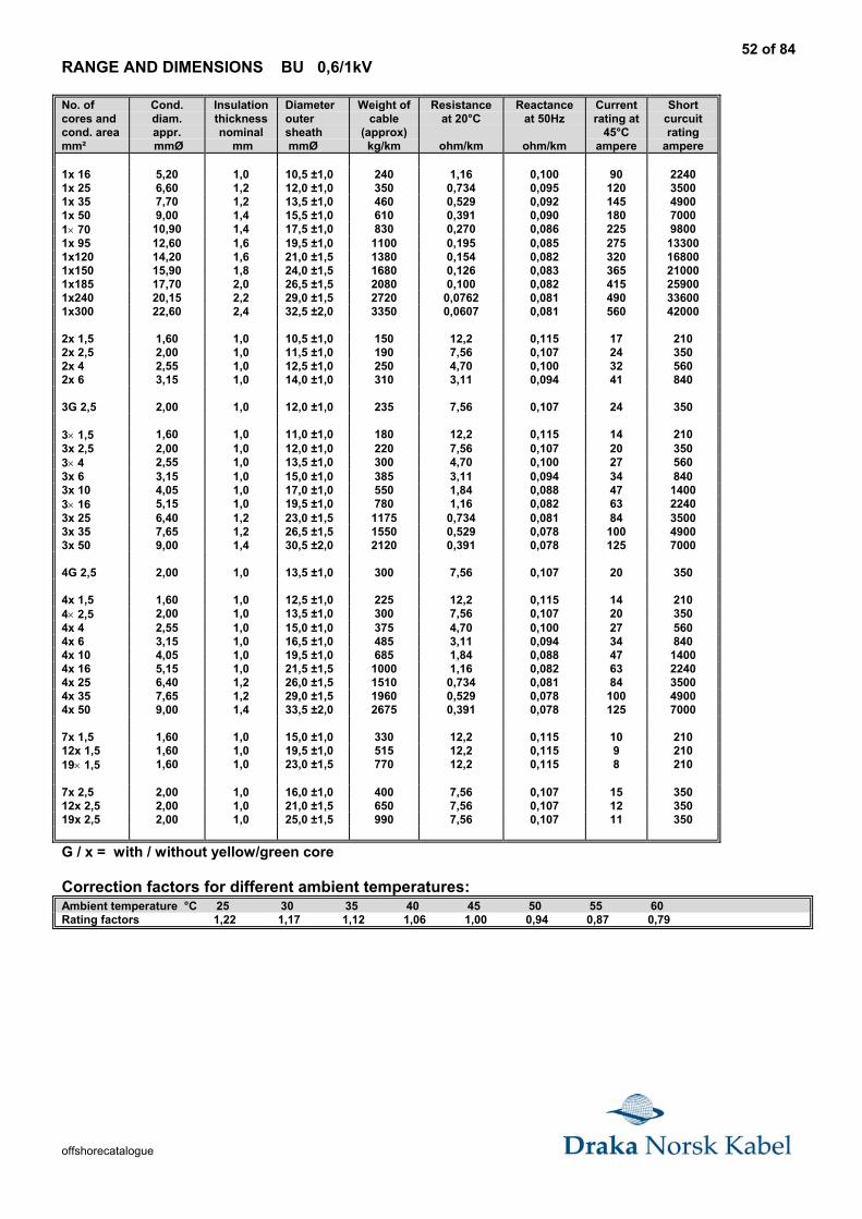
52 of 84
offshorecatalogue
RANGE AND DIMENSIONS BU 0,6/1kV
No. ofcores andcond. areamm²
Cond.diam.appr. mmØ
Insulationthicknessnominal
mm
Diameteroutersheath mmØ
Weight ofcable
(approx)kg/km
Resistanceat 20°C
ohm/km
Reactanceat 50Hz
ohm/km
Currentrating at
45°Campere
Shortcurcuitrating
ampere
1x 16 5,20 1,0 10,5 ±1,0 240 1,16 0,100 90 22401x 25 6,60 1,2 12,0 ±1,0 350 0,734 0,095 120 35001x 35 7,70 1,2 13,5 ±1,0 460 0,529 0,092 145 49001x 50 9,00 1,4 15,5 ±1,0 610 0,391 0,090 180 70001× 70 10,90 1,4 17,5 ±1,0 830 0,270 0,086 225 98001x 95 12,60 1,6 19,5 ±1,0 1100 0,195 0,085 275 133001x120 14,20 1,6 21,0 ±1,5 1380 0,154 0,082 320 168001x150 15,90 1,8 24,0 ±1,5 1680 0,126 0,083 365 210001x185 17,70 2,0 26,5 ±1,5 2080 0,100 0,082 415 259001x240 20,15 2,2 29,0 ±1,5 2720 0,0762 0,081 490 336001x300 22,60 2,4 32,5 ±2,0 3350 0,0607 0,081 560 42000
2x 1,5 1,60 1,0 10,5 ±1,0 150 12,2 0,115 17 2102x 2,5 2,00 1,0 11,5 ±1,0 190 7,56 0,107 24 3502x 4 2,55 1,0 12,5 ±1,0 250 4,70 0,100 32 5602x 6 3,15 1,0 14,0 ±1,0 310 3,11 0,094 41 840
3G 2,5 2,00 1,0 12,0 ±1,0 235 7,56 0,107 24 350
3× 1,5 1,60 1,0 11,0 ±1,0 180 12,2 0,115 14 2103x 2,5 2,00 1,0 12,0 ±1,0 220 7,56 0,107 20 3503× 4 2,55 1,0 13,5 ±1,0 300 4,70 0,100 27 5603x 6 3,15 1,0 15,0 ±1,0 385 3,11 0,094 34 8403x 10 4,05 1,0 17,0 ±1,0 550 1,84 0,088 47 14003× 16 5,15 1,0 19,5 ±1,0 780 1,16 0,082 63 22403x 25 6,40 1,2 23,0 ±1,5 1175 0,734 0,081 84 35003x 35 7,65 1,2 26,5 ±1,5 1550 0,529 0,078 100 49003x 50 9,00 1,4 30,5 ±2,0 2120 0,391 0,078 125 7000
4G 2,5 2,00 1,0 13,5 ±1,0 300 7,56 0,107 20 350
4x 1,5 1,60 1,0 12,5 ±1,0 225 12,2 0,115 14 2104× 2,5 2,00 1,0 13,5 ±1,0 300 7,56 0,107 20 3504x 4 2,55 1,0 15,0 ±1,0 375 4,70 0,100 27 5604x 6 3,15 1,0 16,5 ±1,0 485 3,11 0,094 34 8404x 10 4,05 1,0 19,5 ±1,0 685 1,84 0,088 47 14004x 16 5,15 1,0 21,5 ±1,5 1000 1,16 0,082 63 22404x 25 6,40 1,2 26,0 ±1,5 1510 0,734 0,081 84 35004x 35 7,65 1,2 29,0 ±1,5 1960 0,529 0,078 100 49004x 50 9,00 1,4 33,5 ±2,0 2675 0,391 0,078 125 7000
7x 1,5 1,60 1,0 15,0 ±1,0 330 12,2 0,115 10 21012x 1,5 1,60 1,0 19,5 ±1,0 515 12,2 0,115 9 21019× 1,5 1,60 1,0 23,0 ±1,5 770 12,2 0,115 8 210
7x 2,5 2,00 1,0 16,0 ±1,0 400 7,56 0,107 15 35012x 2,5 2,00 1,0 21,0 ±1,5 650 7,56 0,107 12 35019x 2,5 2,00 1,0 25,0 ±1,5 990 7,56 0,107 11 350
G / x = with / without yellow/green core
Correction factors for different ambient temperatures:Ambient temperature °C 25 30 35 40 45 50 55 60Rating factors 1,22 1,17 1,12 1,06 1,00 0,94 0,87 0,79
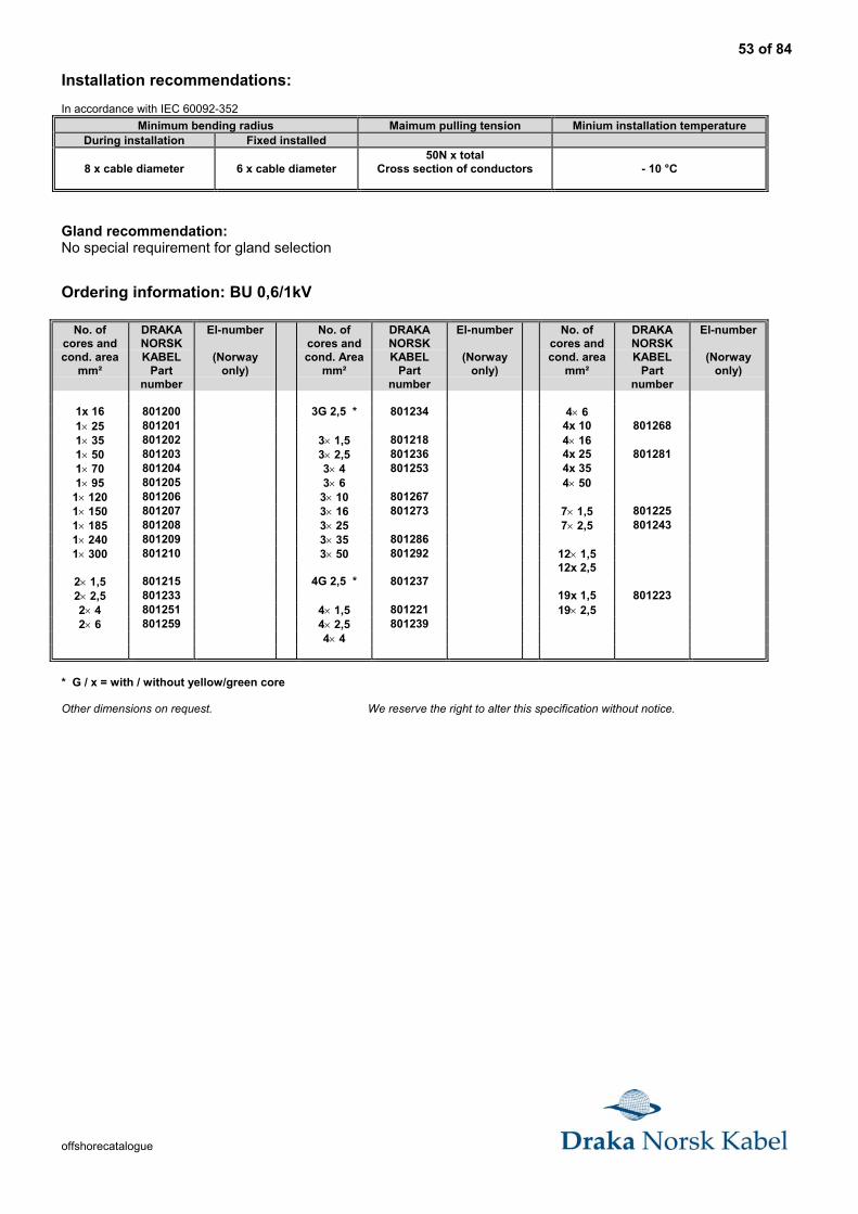
53 of 84
offshorecatalogue
Installation recommendations:
In accordance with IEC 60092-352
Minimum bending radius Maimum pulling tension Minium installation temperatureDuring installation Fixed installed
8 x cable diameter 6 x cable diameter50N x total
Cross section of conductors - 10 °C
Gland recommendation:No special requirement for gland selection
Ordering information: BU 0,6/1kV
No. ofcores andcond. area
mm²
DRAKANORSKKABEL
Partnumber
El-number
(Norwayonly)
No. ofcores andcond. Area
mm²
DRAKANORSKKABEL
Partnumber
El-number
(Norwayonly)
No. ofcores andcond. area
mm²
DRAKANORSKKABEL
Partnumber
El-number
(Norwayonly)
1x 16 801200 3G 2,5 * 801234 4× 61× 25 801201 4x 10 8012681× 35 801202 3× 1,5 801218 4× 161× 50 801203 3× 2,5 801236 4x 25 8012811× 70 801204 3× 4 801253 4x 351× 95 801205 3× 6 4× 50
1× 120 801206 3× 10 8012671× 150 801207 3× 16 801273 7× 1,5 8012251× 185 801208 3× 25 7× 2,5 8012431× 240 801209 3× 35 8012861× 300 801210 3× 50 801292 12× 1,5
12x 2,52× 1,5 801215 4G 2,5 * 8012372× 2,5 801233 19x 1,5 8012232× 4 801251 4× 1,5 801221 19× 2,52× 6 801259 4× 2,5 801239
4× 4
* G / x = with / without yellow/green core
Other dimensions on request. We reserve the right to alter this specification without notice.
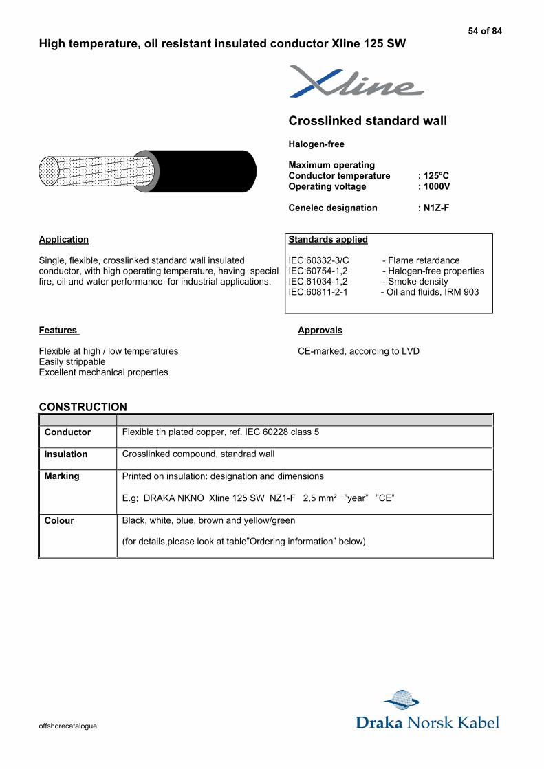
54 of 84
offshorecatalogue
High temperature, oil resistant insulated conductor Xline 125 SW
������������������������������������������������������������������������������������������������������������������������������������������������������������������������������������������������������������������������������������������������
������������������������������������������������
Crosslinked standard wall
Halogen-free
Maximum operatingConductor temperature : 125°COperating voltage : 1000V
Cenelec designation : N1Z-F
Application
Single, flexible, crosslinked standard wall insulatedconductor, with high operating temperature, having specialfire, oil and water performance for industrial applications.
Standards applied
IEC:60332-3/C - Flame retardanceIEC:60754-1,2 - Halogen-free propertiesIEC:61034-1,2 - Smoke densityIEC:60811-2-1 - Oil and fluids, IRM 903
Features Approvals
Flexible at high / low temperatures CE-marked, according to LVDEasily strippableExcellent mechanical properties
CONSTRUCTION
Conductor Flexible tin plated copper, ref. IEC 60228 class 5
Insulation Crosslinked compound, standrad wall
Marking Printed on insulation: designation and dimensions
E.g; DRAKA NKNO Xline 125 SW NZ1-F 2,5 mm² ”year” ”CE”
Colour Black, white, blue, brown and yellow/green
(for details,please look at table”Ordering information” below)
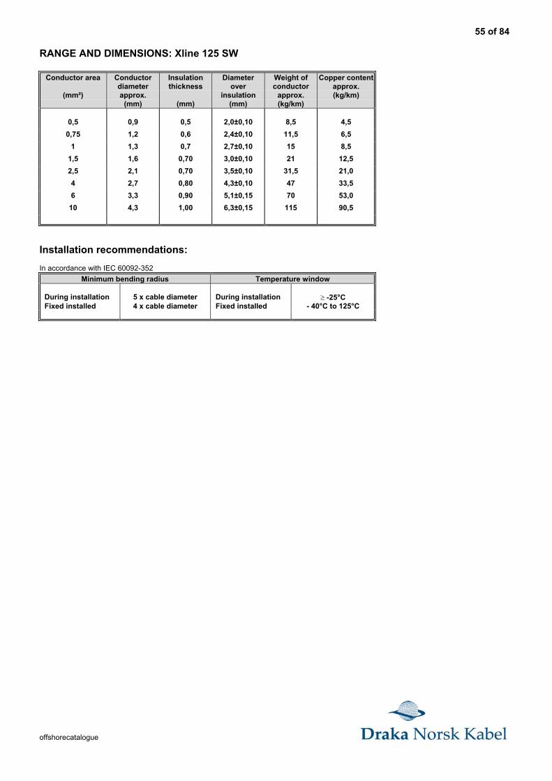
55 of 84
offshorecatalogue
RANGE AND DIMENSIONS: Xline 125 SW
Conductor area
(mm²)
Conductordiameterapprox.
(mm)
Insulationthickness
(mm)
Diameterover
insulation(mm)
Weight ofconductor
approx.(kg/km)
Copper contentapprox.(kg/km)
0,5 0,9 0,5 2,0±0,10 8,5 4,5
0,75 1,2 0,6 2,4±0,10 11,5 6,5
1 1,3 0,7 2,7±0,10 15 8,5
1,5 1,6 0,70 3,0±0,10 21 12,5
2,5 2,1 0,70 3,5±0,10 31,5 21,0
4 2,7 0,80 4,3±0,10 47 33,5
6 3,3 0,90 5,1±0,15 70 53,0
10 4,3 1,00 6,3±0,15 115 90,5
Installation recommendations:
In accordance with IEC 60092-352
Minimum bending radius Temperature window
During installation 5 x cable diameter During installation ≥ -25°CFixed installed 4 x cable diameter Fixed installed - 40°C to 125°C
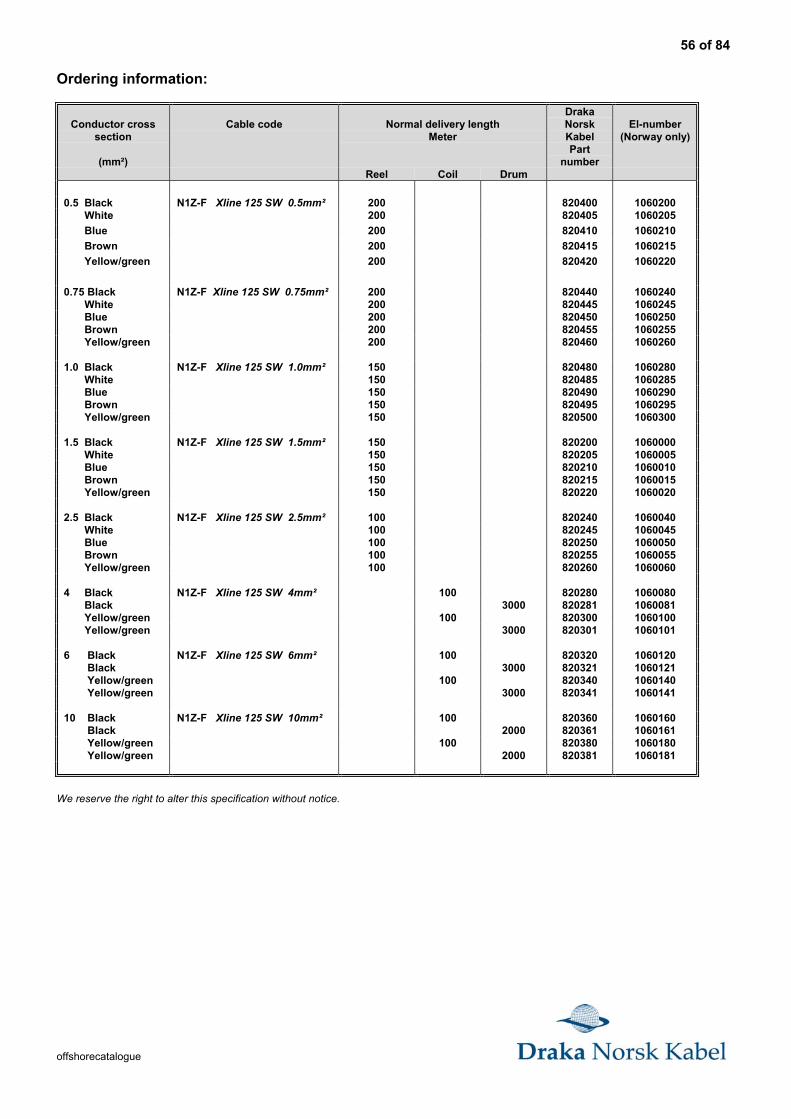
56 of 84
offshorecatalogue
Ordering information:
Conductor crosssection
(mm²)
Cable code Normal delivery lengthMeter
DrakaNorskKabelPart
number
El-number(Norway only)
Reel Coil Drum
0.5 Black N1Z-F Xline 125 SW 0.5mm² 200 820400 1060200 White 200 820405 1060205
Blue 200 820410 1060210
Brown 200 820415 1060215
Yellow/green 200 820420 1060220
0.75 Black N1Z-F Xline 125 SW 0.75mm² 200 820440 1060240 White 200 820445 1060245 Blue 200 820450 1060250 Brown 200 820455 1060255 Yellow/green 200 820460 1060260
1.0 Black N1Z-F Xline 125 SW 1.0mm² 150 820480 1060280 White 150 820485 1060285 Blue 150 820490 1060290 Brown 150 820495 1060295 Yellow/green 150 820500 1060300
1.5 Black N1Z-F Xline 125 SW 1.5mm² 150 820200 1060000 White 150 820205 1060005 Blue 150 820210 1060010 Brown 150 820215 1060015 Yellow/green 150 820220 1060020
2.5 Black N1Z-F Xline 125 SW 2.5mm² 100 820240 1060040 White 100 820245 1060045 Blue 100 820250 1060050 Brown 100 820255 1060055 Yellow/green 100 820260 1060060
4 Black N1Z-F Xline 125 SW 4mm² 100 820280 1060080 Black 3000 820281 1060081 Yellow/green 100 820300 1060100 Yellow/green 3000 820301 1060101
6 Black N1Z-F Xline 125 SW 6mm² 100 820320 1060120 Black 3000 820321 1060121 Yellow/green 100 820340 1060140 Yellow/green 3000 820341 1060141
10 Black N1Z-F Xline 125 SW 10mm² 100 820360 1060160 Black 2000 820361 1060161 Yellow/green 100 820380 1060180 Yellow/green 2000 820381 1060181
We reserve the right to alter this specification without notice.
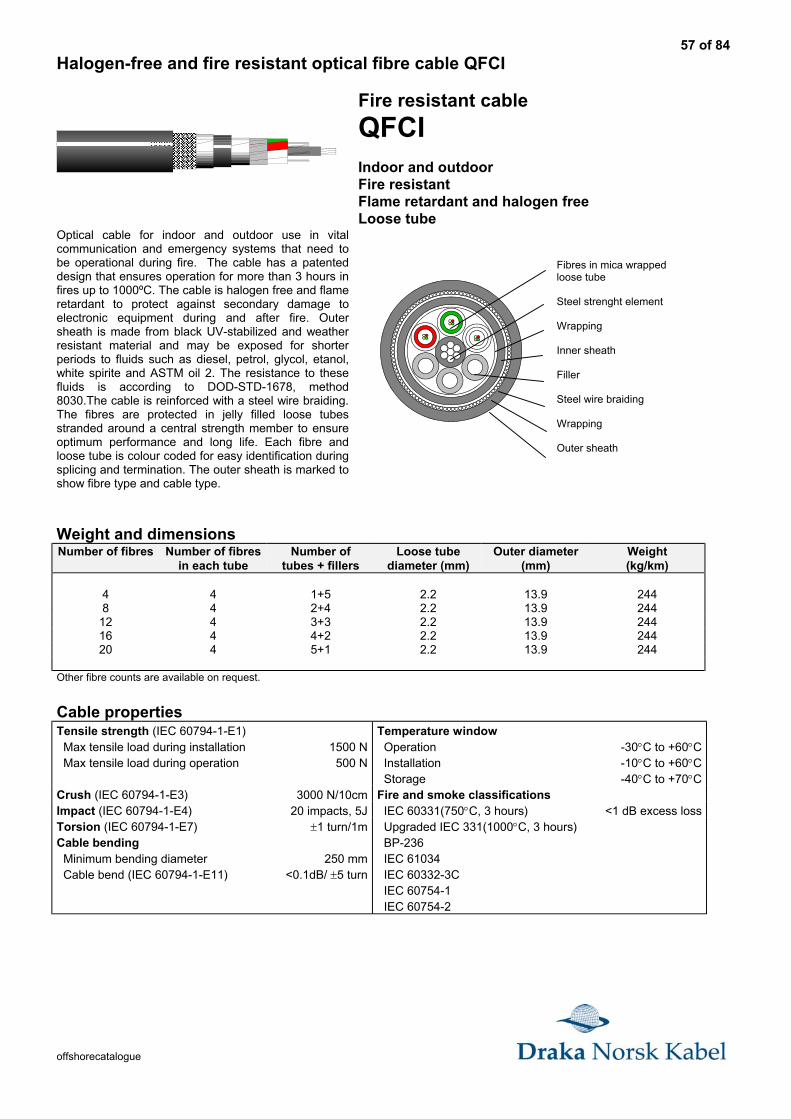
57 of 84
offshorecatalogue
Halogen-free and fire resistant optical fibre cable QFCI
������������������������������������������������������������������������
Optical cable for indoor and outdoor use in vitalcommunication and emergency systems that need tobe operational during fire. The cable has a patenteddesign that ensures operation for more than 3 hours infires up to 1000ºC. The cable is halogen free and flameretardant to protect against secondary damage toelectronic equipment during and after fire. Outersheath is made from black UV-stabilized and weatherresistant material and may be exposed for shorterperiods to fluids such as diesel, petrol, glycol, etanol,white spirite and ASTM oil 2. The resistance to thesefluids is according to DOD-STD-1678, method8030.The cable is reinforced with a steel wire braiding.The fibres are protected in jelly filled loose tubesstranded around a central strength member to ensureoptimum performance and long life. Each fibre andloose tube is colour coded for easy identification duringsplicing and termination. The outer sheath is marked toshow fibre type and cable type.
Fire resistant cable
QFCIIndoor and outdoorFire resistantFlame retardant and halogen freeLoose tube
Weight and dimensionsNumber of fibres Number of fibres
in each tubeNumber of
tubes + fillersLoose tube
diameter (mm)Outer diameter
(mm)Weight(kg/km)
4 4 1+5 2.2 13.9 2448 4 2+4 2.2 13.9 244
12 4 3+3 2.2 13.9 24416 4 4+2 2.2 13.9 24420 4 5+1 2.2 13.9 244
Other fibre counts are available on request.
Cable propertiesTensile strength (IEC 60794-1-E1) Max tensile load during installation Max tensile load during operation
1500 N500 N
Temperature window Operation Installation Storage
-30°C to +60°C-10°C to +60°C-40°C to +70°C
Crush (IEC 60794-1-E3) 3000 N/10cm Fire and smoke classificationsImpact (IEC 60794-1-E4) 20 impacts, 5J IEC 60331(750°C, 3 hours) <1 dB excess lossTorsion (IEC 60794-1-E7)Cable bending Minimum bending diameter Cable bend (IEC 60794-1-E11)
±1 turn/1m
250 mm<0.1dB/ ±5 turn
Upgraded IEC 331(1000°C, 3 hours) BP-236 IEC 61034 IEC 60332-3C IEC 60754-1 IEC 60754-2
Fibres in mica wrappedloose tube
Steel strenght element
Wrapping
Inner sheath
Filler
Steel wire braiding
Wrapping
Outer sheath
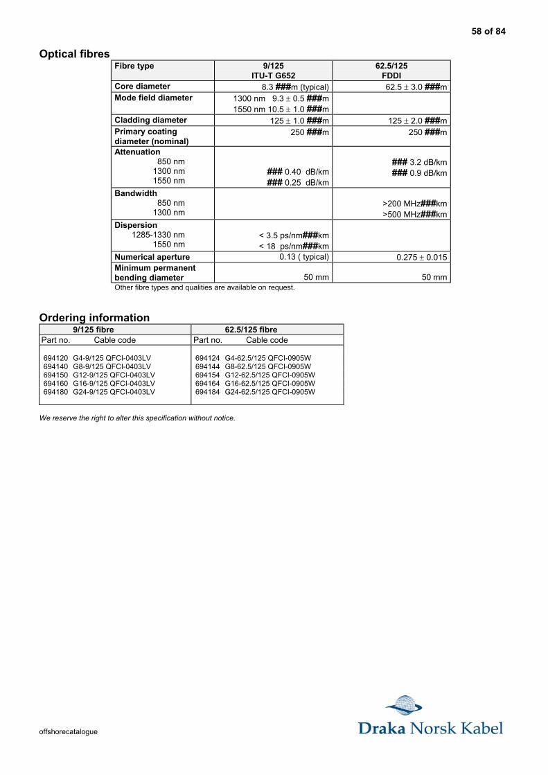
58 of 84
offshorecatalogue
Optical fibresFibre type 9/125
ITU-T G65262.5/125
FDDICore diameter 8.3 ###m (typical) 62.5 ± 3.0 ###mMode field diameter 1300 nm 9.3 ± 0.5 ###m
1550 nm 10.5 ± 1.0 ###mCladding diameter 125 ± 1.0 ###m 125 ± 2.0 ###mPrimary coatingdiameter (nominal)
250 ###m 250 ###m
Attenuation 850 nm 1300 nm 1550 nm
### 0.40 dB/km ### 0.25 dB/km
### 3.2 dB/km ### 0.9 dB/km
Bandwidth 850 nm 1300 nm
>200 MHz###km>500 MHz###km
Dispersion 1285-1330 nm
1550 nm< 3.5 ps/nm###km< 18 ps/nm###km
Numerical aperture 0.13 ( typical) 0.275 ± 0.015Minimum permanentbending diameter 50 mm 50 mmOther fibre types and qualities are available on request.
Ordering information9/125 fibre 62.5/125 fibre
Part no. Cable code Part no. Cable code
694120 G4-9/125 QFCI-0403LV 694124 G4-62.5/125 QFCI-0905W694140 G8-9/125 QFCI-0403LV 694144 G8-62.5/125 QFCI-0905W694150 G12-9/125 QFCI-0403LV 694154 G12-62.5/125 QFCI-0905W694160 G16-9/125 QFCI-0403LV 694164 G16-62.5/125 QFCI-0905W694180 G24-9/125 QFCI-0403LV 694184 G24-62.5/125 QFCI-0905W
We reserve the right to alter this specification without notice.

59 of 84
offshorecatalogue
Approvals
Our cables carry these major approvals:
DETNORSKEVERITAS
GERMANISCHERLLOYD
AMERICANBUREAU
OFSHIPPING
LLOYDSREGISTER
OFSHIPPING
BUREAUVERITAS
RUSSIANMARITIMEREGISTER
OFSHIPPING
RFOU 250 V (c) (i)
RU 250V (c) (i)
RFOU 0,6/1 kV
RU 0,6/1 kV
RFOU 6/10 kV
RFOU 12/20 kV
BFOU 250 V (c) (i)
BU 250V (i) (c)
BFOU 0,6/1 kV
BU 0,6/1kV
QFCI
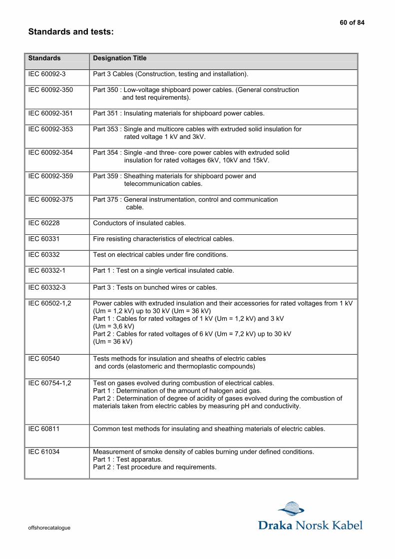
60 of 84
offshorecatalogue
Standards and tests:
Standards Designation Title
IEC 60092-3 Part 3 Cables (Construction, testing and installation).
IEC 60092-350 Part 350 : Low-voltage shipboard power cables. (General construction and test requirements).
IEC 60092-351 Part 351 : Insulating materials for shipboard power cables.
IEC 60092-353 Part 353 : Single and multicore cables with extruded solid insulation for rated voltage 1 kV and 3kV.
IEC 60092-354 Part 354 : Single -and three- core power cables with extruded solid insulation for rated voltages 6kV, 10kV and 15kV.
IEC 60092-359 Part 359 : Sheathing materials for shipboard power and telecommunication cables.
IEC 60092-375 Part 375 : General instrumentation, control and communication cable.
IEC 60228 Conductors of insulated cables.
IEC 60331 Fire resisting characteristics of electrical cables.
IEC 60332 Test on electrical cables under fire conditions.
IEC 60332-1 Part 1 : Test on a single vertical insulated cable.
IEC 60332-3 Part 3 : Tests on bunched wires or cables.
IEC 60502-1,2 Power cables with extruded insulation and their accessories for rated voltages from 1 kV(Um = 1,2 kV) up to 30 kV (Um = 36 kV)Part 1 : Cables for rated voltages of 1 kV (Um = 1,2 kV) and 3 kV(Um = 3,6 kV)Part 2 : Cables for rated voltages of 6 kV (Um = 7,2 kV) up to 30 kV(Um = 36 kV)
IEC 60540 Tests methods for insulation and sheaths of electric cables and cords (elastomeric and thermoplastic compounds)
IEC 60754-1,2 Test on gases evolved during combustion of electrical cables.Part 1 : Determination of the amount of halogen acid gas.Part 2 : Determination of degree of acidity of gases evolved during the combustion ofmaterials taken from electric cables by measuring pH and conductivity.
IEC 60811 Common test methods for insulating and sheathing materials of electric cables.
IEC 61034 Measurement of smoke density of cables burning under defined conditions.Part 1 : Test apparatus.Part 2 : Test procedure and requirements.
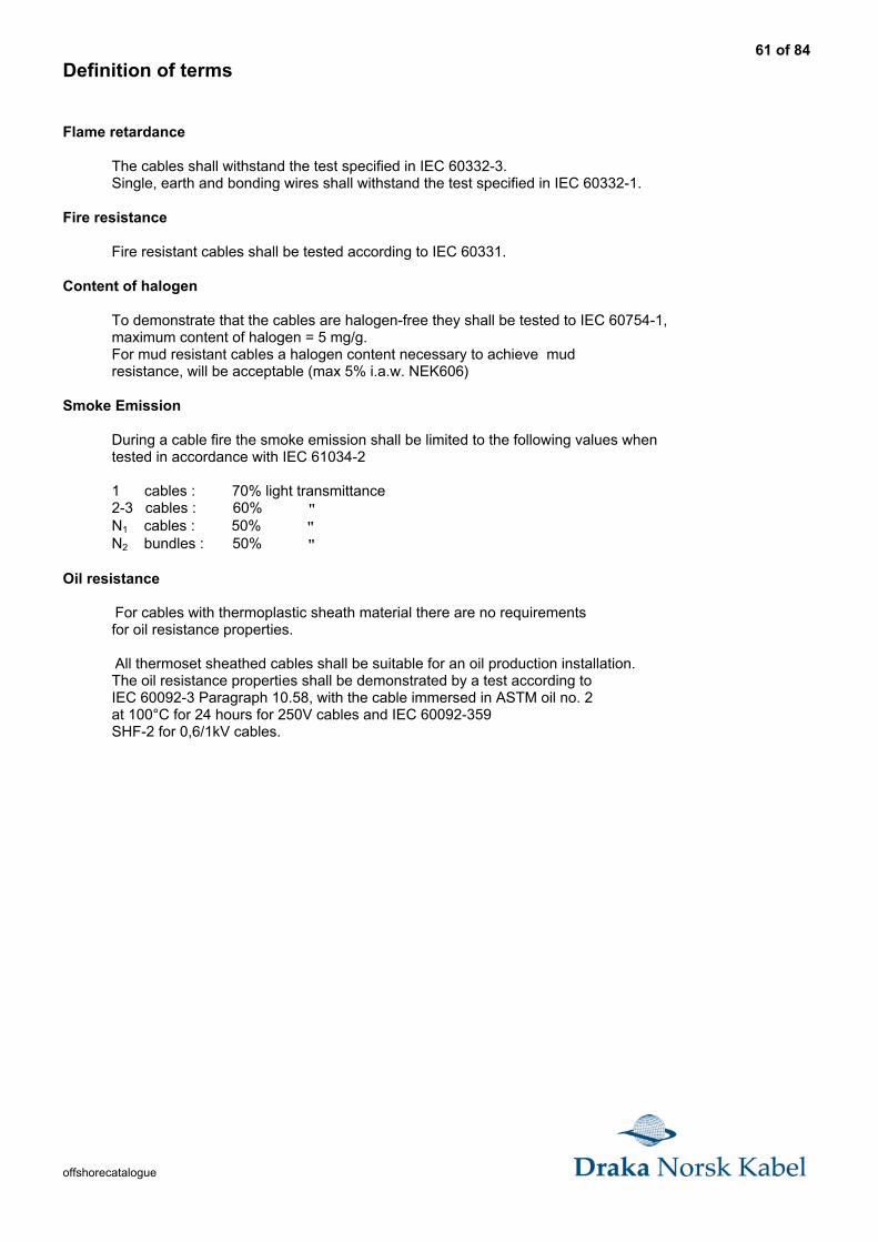
61 of 84
offshorecatalogue
Definition of terms
Flame retardance
The cables shall withstand the test specified in IEC 60332-3. Single, earth and bonding wires shall withstand the test specified in IEC 60332-1.
Fire resistance
Fire resistant cables shall be tested according to IEC 60331.
Content of halogen
To demonstrate that the cables are halogen-free they shall be tested to IEC 60754-1, maximum content of halogen = 5 mg/g. For mud resistant cables a halogen content necessary to achieve mud resistance, will be acceptable (max 5% i.a.w. NEK606)
Smoke Emission
During a cable fire the smoke emission shall be limited to the following values when tested in accordance with IEC 61034-2
1 cables : 70% light transmittance 2-3 cables : 60% " N1 cables : 50% " N2 bundles : 50% "
Oil resistance
For cables with thermoplastic sheath material there are no requirements for oil resistance properties.
All thermoset sheathed cables shall be suitable for an oil production installation. The oil resistance properties shall be demonstrated by a test according to IEC 60092-3 Paragraph 10.58, with the cable immersed in ASTM oil no. 2 at 100°C for 24 hours for 250V cables and IEC 60092-359 SHF-2 for 0,6/1kV cables.
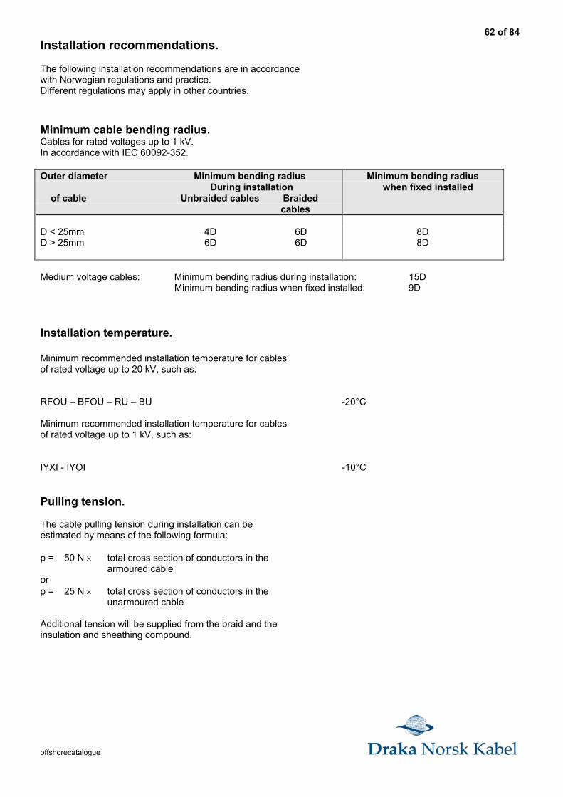
62 of 84
offshorecatalogue
Installation recommendations.
The following installation recommendations are in accordancewith Norwegian regulations and practice.Different regulations may apply in other countries.
Minimum cable bending radius.Cables for rated voltages up to 1 kV.In accordance with IEC 60092-352.
Outer diameter Minimum bending radius During installation of cable Unbraided cables Braided cables
Minimum bending radius when fixed installed
D < 25mm 4D 6DD > 25mm 6D 6D
8D8D
Medium voltage cables: Minimum bending radius during installation: 15D Minimum bending radius when fixed installed: 9D
Installation temperature.
Minimum recommended installation temperature for cablesof rated voltage up to 20 kV, such as:
RFOU – BFOU – RU – BU -20°C
Minimum recommended installation temperature for cablesof rated voltage up to 1 kV, such as:
IYXI - IYOI -10°C
Pulling tension.
The cable pulling tension during installation can beestimated by means of the following formula:
p = 50 N × total cross section of conductors in thearmoured cable
orp = 25 N × total cross section of conductors in the
unarmoured cable
Additional tension will be supplied from the braid and theinsulation and sheathing compound.

63 of 84
offshorecatalogue
Explosion risk areas.1. AreasThe areas on board are usually classified in twomain categories as regards the explosion risk;
• hazardous areas• safe areas
A hazardous area is divided into three zones;
• zone 0 • zone 1
• zone 2
2. Installation of cablesFor cables to be used in zone 0 and zone 1, oneof the following types of protection is required:
• A non-metallic outer sheath in combination with braiding or other metallic covering for earth fault detection and mechanical protection. A non-metallic outer sheath is, however, not required if the
screen or armouring consists of a corrosion resistant bronze alloy.• A lead sheathing in addition to further mechanical protection, for example armour braiding or
non-metallic impervious sheath.• For mineral insulated cables, a copper or stainless steel sheath.
Single core cables in installations with AC or DC current with a high ripple content should be of types withoutscreen or armouring. Where mechanical damage is possible, such cables should otherwise be mechanicallyprotected or installed in ducts or similar.For installations in zone 2, cables without screen or armour can be used.
Earthing of metal coverings of cables.
1. General requirementsAll metal coverings of cables, armouring or shielding shall be earthed. Earthing must be provided at both endsexcept for final sub-circuits where earthing at only one end (the supply end) is sufficient. Earthing at one end ispermitted where it is required for technical or safety reasons, control and instrumentation cables, mineralinsulated cables, intrinsically safe circuits, control circuits, etc.
Metal covering of single core cables for AC and single core cables for DC with ripple content exceeding 10%and having a current rating exceeding 20A is to be earthed at one and only.When single core cables for AC and DC with ripple content higher than 10% are installed in or passing throughhazardous areas, the metal screen or armour is to be earthed inside the hazardous area to avoid dangerouspotential between screen armour and earthed part of the installation.
2. Cross section of earth connectionsEarth connections for metal coverings shall be carried out with conductors having cross sectional areas relatedto the cross sectional areas of the phase conductors and the current ratings of the cable, or at least the samecross sectional areas as the metal covering itself.
3. Earthing through metal clamps etc.Metal coverings of cables may be earthed through clamps. The clamps must grip the metal covering of thecable and must be connected to the hull and provide a good conductive connection between the metal coveringand the hull. The metal clamps must be corrosion resistant.
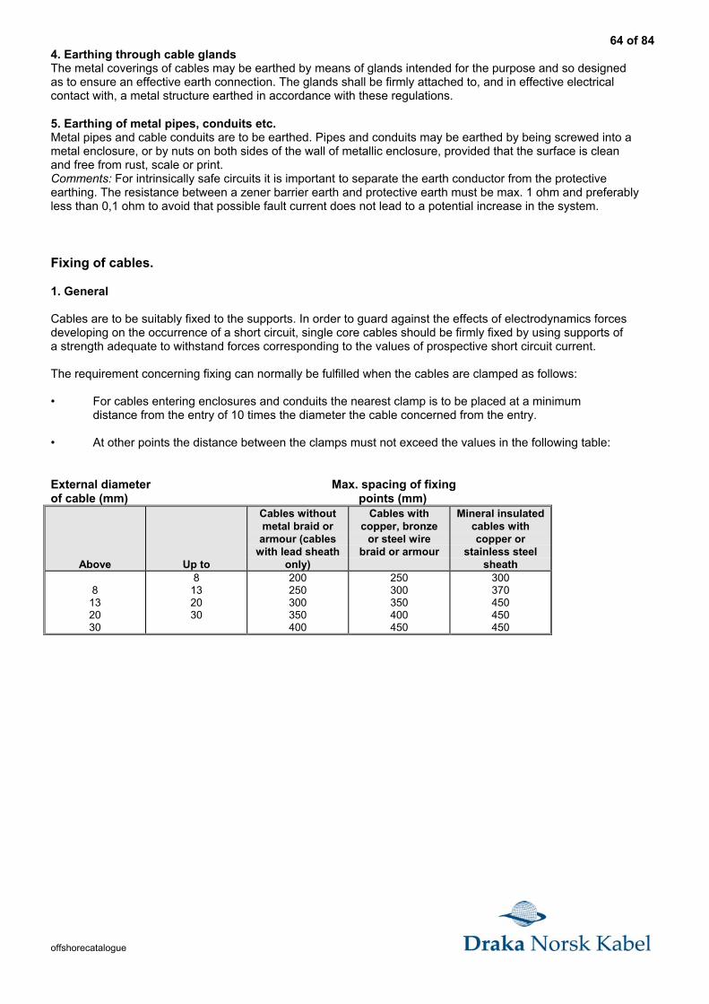
64 of 84
offshorecatalogue
4. Earthing through cable glandsThe metal coverings of cables may be earthed by means of glands intended for the purpose and so designedas to ensure an effective earth connection. The glands shall be firmly attached to, and in effective electricalcontact with, a metal structure earthed in accordance with these regulations.
5. Earthing of metal pipes, conduits etc.Metal pipes and cable conduits are to be earthed. Pipes and conduits may be earthed by being screwed into ametal enclosure, or by nuts on both sides of the wall of metallic enclosure, provided that the surface is cleanand free from rust, scale or print.Comments: For intrinsically safe circuits it is important to separate the earth conductor from the protectiveearthing. The resistance between a zener barrier earth and protective earth must be max. 1 ohm and preferablyless than 0,1 ohm to avoid that possible fault current does not lead to a potential increase in the system.
Fixing of cables.
1. General
Cables are to be suitably fixed to the supports. In order to guard against the effects of electrodynamics forcesdeveloping on the occurrence of a short circuit, single core cables should be firmly fixed by using supports ofa strength adequate to withstand forces corresponding to the values of prospective short circuit current.
The requirement concerning fixing can normally be fulfilled when the cables are clamped as follows:
• For cables entering enclosures and conduits the nearest clamp is to be placed at a minimumdistance from the entry of 10 times the diameter the cable concerned from the entry.
• At other points the distance between the clamps must not exceed the values in the following table:
External diameter Max. spacing of fixingof cable (mm) points (mm)
Above Up to
Cables withoutmetal braid orarmour (cables
with lead sheathonly)
Cables withcopper, bronze
or steel wirebraid or armour
Mineral insulatedcables withcopper or
stainless steelsheath
8132030
8132030
200250300350400
250300350400450
300370450450450
65 of 84
offshorecatalogue
Mechanical protection of cables.
Cables are to be installed in such a way that they are not subject to damaging mechanical stressed.Where this can not be obtained the cables are to be protected.Unless the cable itself (for example armour or sheath) provides adequate protection the cables should be;
• Enclosed in suitable conduits or casings• Covered by steelplates or profiles• Steel pipes in which the cables are run
In areas where there is an exceptional risk of mechanical damage, for example in cargo hold area ordifferent storage areas, the cables always have to be protected, even when the cables are armoured.The thickness of the protective conduits must be at least 4 mm. The wall thickness of the protective conduitmust be at least 2 mm.Cables lay on aluminium supports may have a corresponding protection of aluminium.The thickness must be at least 4 mm.Metal casing used for mechanical protection of cables should be efficiently protected against corrosion.
Installation of cables.Fire properties.Cables must at lest meet the flame retardant requirements. On board passenger ships, cargo-ships andmobile offshore units, where not otherwise stated cables must be installed as not to impair the original flameretarding properties. These requirements are considered to be satisfied if the cables have characteristicscomplying with the cable bunch test in IEC- Publication 60332-3, or fire stops are installed in accordance withthe following recommendations:
When cables complying with single-cable test, but not the cable-bunch-test, are installed, fire stops are to beprovided in enclosed or semi-enclosed spaces except for cargo rooms and tunnels in cargo areas.a) For vertical cable runs.
• with a max. distance between fire stops of two decks or 6 metres, unless installed in totally enclosed cable ducts• at the main and the emergency switchboard• where cables enter into an engine control room• at centralised control panels for propulsion machinery and essential auxiliaries• at the entrance to cable ducts
b) For horizontal cable runs.• as a) above, but the max. distance between fire stops may be increased to 14 m.
When choosing cable types special attention should be paid to reduce possible damage due to corrosion incase of a fire. Non-halogen free cables (materials) will give off corrosive gases during a fire. The corrosioneffect depends on the amount of halogens in the materials used.
Flame retardant cables are to have characteristics complying with the test requirements in IEC- Publication60332-1, with amendments.
Fire resistant cables are to have characteristics complying with the test requirements in IEC- publication 60331.
Alternative tests may be considered, depending on the present functional requirements.
Cables and wires serving essential or emergency power, lightning, internal communication or signals shall asfar as possible be routed clear of galleys, laundries, machinery spaces (Class A according to IMO) and theircasings and other high fire risk areas. Cables connecting fire pumps to the emergency switchboard should bea fire resistant where they pass through high fire risk areas. The Norwegian Maritime Directorate (NMD) andthe Norwegian Petroleum Directorate (NPD) may for circuits to special services require use of fire resistantcables.
66 of 84
offshorecatalogue
Circuits of the following services may be considered:
• cables for emergency power systems e.g. fire pumps.• cables for fire - extinguishing systems.• control cables for water tight doors.• control cables for ballast system unless when these are duplicated.• essential alarms cables.• Cables for lifts.
Intrinsically safe installationsCables and flexible cables for intrinsically safe circuits must have screen or similar of a conducting materialand the outer sheath must be of an insulating material. A non-metallic outer sheath is, however, not requiredif the screen or armour consists of a corrosion resistant bronze alloy. Where there is no danger of interferencefrom the external electrical or magnetic fields, short flexible cables may be used without screen.
1. Associated equipmentAssociated equipment (e.g. power supply units) shall be situated in a safe area or has protection as mentionedin “Explosion risk areas”.
2. Connection of equipmentWithin limitations laid down in 3., ordinary non-explosion protected equipment may be connected to intrinsicallysafe equipment, provided that it is designed to meet regulations in other respects.
3. Compliance with any limitations in the certificate.With intrinsically safe circuits special considerations must be given to ensure that the circuits characteristics(including connected equipment, cables, conductors etc.) satisfy any limitations in the test certificate.Such limitations may be maximum values for capacitance and inductance etc. It is pointed out there is adanger of damage to i.s equipment when using normal equipment for insulation testing.
4. Adjacent locationConductors for i.s safe circuits and conductors for non- i.s safe circuits shall not be run together in the samecable, flexible cable, conduit, cable bunch etc.
5. Protection against electrical and magnetic fieldsWhere i.s circuits are exposed to magnetic or electrical fields that may destroy the intrinsic safety of thesystem, precautions must be taken during installation.
Such precautions may be:
• cables for i.s circuits and non i.s circuits to be installed a minimum distance of 50 mm apart.The minimum distance to heavy current cables using D.C with a high ripple content should be300 mm.
• cables for i.s circuits and non i.s circuits to be separated panel of conducting material whichis earthed.
• cables for i.s circuits to have effective transposition.
6. MarkingThe marking may be a marking plate or by colour marking of the cables, when using colour marking,the colour should be light blue.
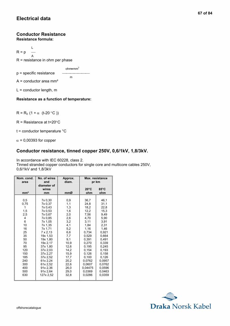
67 of 84
offshorecatalogue
Electrical data
Conductor ResistanceResistance formula:
LR = p AR = resistance in ohm per phase
ohm•mm2
p = specific resistance mA = conductor area mm²
L = conductor length, m
Resistance as a function of temperature:
R = R0 (1 + α (t-20 °C ))
R = Resistance at t=20°C
t = conductor temperature °C
α = 0,00393 for copper
Conductor resistance, tinned copper 250V, 0,6/1kV, 1,8/3kV.
In accordance with IEC 60228, class 2.Tinned stranded copper conductors for single core and multicore cables 250V,0,6/1kV and 1,8/3kV
Nom. cond.area
mm²
No. of wiresand
diameter ofwiresmm
Approx.diam.
mmØ
Max. resistancepr km
20°C 85°C ohm ohm
0,5 7x 0,30 0,9 36,7 46,10,75 7x 0,37 1,1 24,8 31,1
1 7x 0,43 1,3 18,2 22,81,5 7x 0,53 1,6 12,2 15,32,5 7x 0,67 2,0 7,56 9,494 7x 0,85 2,6 4,70 5,906 7x 1,05 3,2 3,11 3,91
10 7x 1,35 4,1 1,84 2,3116 7x 1,71 5,2 1,16 1,4625 7 x 2,13 6,6 0,734 0,92135 19x 1,53 7,7 0,529 0,66450 19x 1,80 9,1 0,391 0,49170 19x 2,17 10,9 0,270 0,33995 37x 1,80 12,6 0,195 0,245
120 37x 2,03 14,2 0,154 0,193150 37x 2,27 15,9 0,126 0,158185 37x 2,52 17,7 0,100 0,126240 61x 2,24 20,2 0,0762 0,0957300 61x 2,52 22,6 0,0607 0,0762400 91x 2,36 26,0 0,04475 0,0596500 91x 2,64 29,0 0,0369 0,0463630 127x 2,52 32,8 0,0286 0,0359
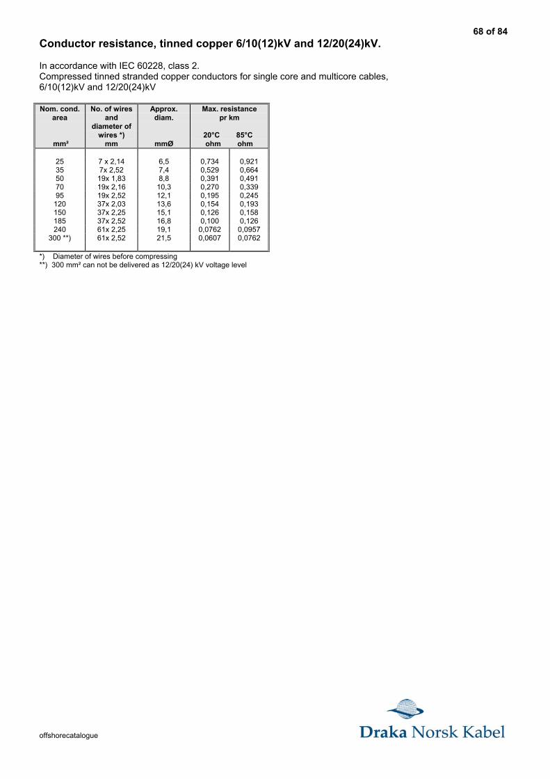
68 of 84
offshorecatalogue
Conductor resistance, tinned copper 6/10(12)kV and 12/20(24)kV.
In accordance with IEC 60228, class 2.Compressed tinned stranded copper conductors for single core and multicore cables,6/10(12)kV and 12/20(24)kV
Nom. cond.area
mm²
No. of wiresand
diameter ofwires *)
mm
Approx.diam.
mmØ
Max. resistancepr km
20°C 85°C ohm ohm
25 7 x 2,14 6,5 0,734 0,92135 7x 2,52 7,4 0,529 0,66450 19x 1,83 8,8 0,391 0,49170 19x 2,16 10,3 0,270 0,33995 19x 2,52 12,1 0,195 0,245
120 37x 2,03 13,6 0,154 0,193150 37x 2,25 15,1 0,126 0,158185 37x 2,52 16,8 0,100 0,126240 61x 2,25 19,1 0,0762 0,0957
300 **) 61x 2,52 21,5 0,0607 0,0762
*) Diameter of wires before compressing**) 300 mm² can not be delivered as 12/20(24) kV voltage level
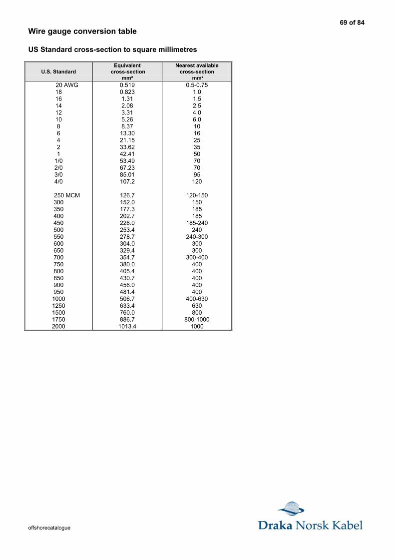
69 of 84
offshorecatalogue
Wire gauge conversion table
US Standard cross-section to square millimetres
U.S. StandardEquivalent
cross-sectionmm²
Nearest availablecross-section
mm² 20 AWG
181614121086421
1/02/03/04/0
250 MCM300350400450500550600650700750800850900950
10001250150017502000
0.5190.8231.312.083.315.268.3713.3021.1533.6242.4153.4967.2385.01107.2
126.7152.0177.3202.7228.0253.4278.7304.0329.4354.7380.0405.4430.7456.0481.4506.7633.4760.0886.7
1013.4
0.5-0.751.01.52.54.06.01016253550707095
120
120-150150185185
185-240240
240-300300300
300-400400400400400400
400-630630800
800-10001000
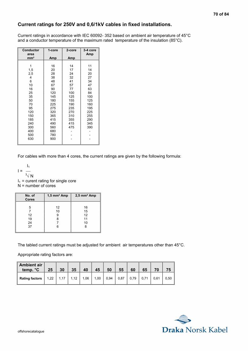
70 of 84
offshorecatalogue
Current ratings for 250V and 0,6/1kV cables in fixed installations.
Current ratings in accordance with IEC 60092- 352 based on ambient air temperature of 45°Cand a conductor temperature of the maximum rated temperature of the insulation (85°C).
Conductorareamm²
1-core
Amp
2-core
Amp
3-4 coreAmp
1 16 14 111,5 20 17 142,5 28 24 204 38 32 276 48 41 34
10 67 57 4716 90 77 6325 120 100 8435 145 125 10050 180 155 12570 225 190 16095 275 235 195
120 320 270 225150 365 310 255185 415 355 290240 490 415 345300 560 475 390400 680 - -500 780 - -630 900 - -
For cables with more than 4 cores, the current ratings are given by the following formula:
I1I = 3√ NI1 = curent rating for single coreN = number of cores
No. ofCores
1,5 mm² Amp 2,5 mm² Amp
5 12 167 10 15
12 9 1219 8 1124 7 1037 6 8
The tabled current ratings must be adjusted for ambient air temperatures other than 45°C.
Appropriate rating factors are:
Ambient airtemp. °C 25 30 35 40 45 50 55 60 65 70 75
Rating factors 1,22 1,17 1,12 1,06 1,00 0,94 0,87 0,79 0,71 0,61 0,50
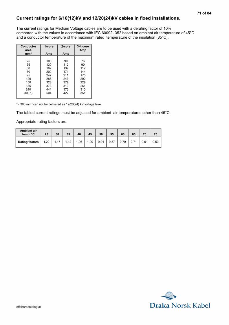
71 of 84
offshorecatalogue
Current ratings for 6/10(12)kV and 12/20(24)kV cables in fixed installations.
The current ratings for Medium Voltage cables are to be used with a derating factor of 10%compared with the values in accordance with IEC 60092- 352 based on ambient air temperature of 45°Cand a conductor temperature of the maximum rated temperature of the insulation (85°C).
Conductorareamm²
1-core
Amp
2-core
Amp
3-4 coreAmp
25 108 90 7635 130 112 9050 162 139 11270 202 171 14495 247 211 175
120 288 243 202150 328 279 229185 373 319 261240 441 373 310
300 *) 504 427 351
*) 300 mm² can not be delivered as 12/20(24) kV voltage level
The tabled current ratings must be adjusted for ambient air temperatures other than 45°C.
Appropriate rating factors are:
Ambient airtemp. °C 25 30 35 40 45 50 55 60 65 70 75
Rating factors 1,22 1,17 1,12 1,06 1,00 0,94 0,87 0,79 0,71 0,61 0,50
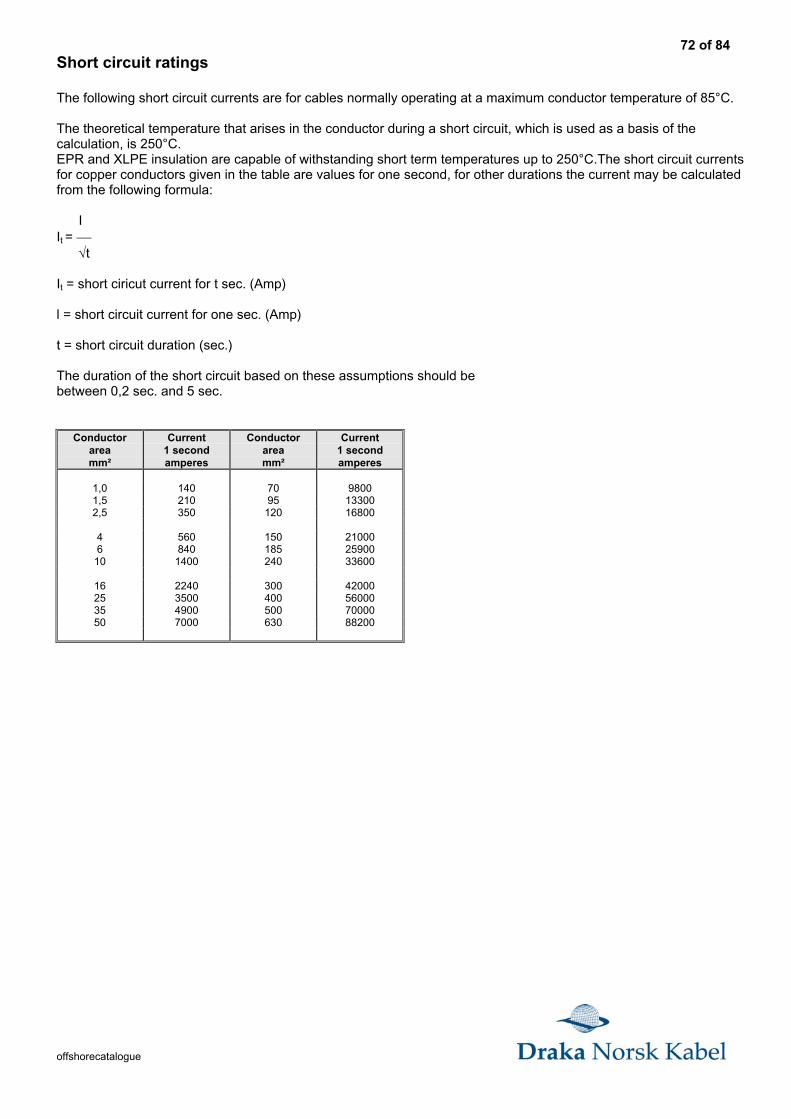
72 of 84
offshorecatalogue
Short circuit ratings
The following short circuit currents are for cables normally operating at a maximum conductor temperature of 85°C.
The theoretical temperature that arises in the conductor during a short circuit, which is used as a basis of thecalculation, is 250°C.EPR and XLPE insulation are capable of withstanding short term temperatures up to 250°C.The short circuit currentsfor copper conductors given in the table are values for one second, for other durations the current may be calculatedfrom the following formula:
IIt = √t
It = short ciricut current for t sec. (Amp)
l = short circuit current for one sec. (Amp)
t = short circuit duration (sec.)
The duration of the short circuit based on these assumptions should bebetween 0,2 sec. and 5 sec.
Conductorareamm²
Current1 secondamperes
Conductorareamm²
Current1 secondamperes
1,0 140 70 98001,5 210 95 133002,5 350 120 16800
4 560 150 210006 840 185 25900
10 1400 240 33600
16 2240 300 4200025 3500 400 5600035 4900 500 7000050 7000 630 88200
73 of 84
offshorecatalogue
ReactanceThe reactance of a cable operating in an AC system depends on many factors, including, in particular, the axial spacingbetween conductors and the proximity and magnetic properties of adjacent steelwork. The former is known formulticore cable, but may vary for single core cables depending upon the spacing between them and their dispositionwhen installed. Reactance of cables in certain disposition when installed. Reactance of cables in certain dispositionsremote from steelwork are calculable and are shown. The tabulated values are for cables with circular conductors. Thevalue for a sector-shaped conductor should be taken as 90% of the calculated value.
Induction for 2-, 3- and 4- conductor cables is given by the formula:
2aL = 0,2 * ( In ( ) + 0,25 ) * 10-6
d
L = Induction in H/m and phasea = Axial space between conductors in mm.d = conductor diameter in mm.
Reactance for 2-, 3- and 4-conductor cables is given by the formula:
X = 2 * π * f * L * IX = Reactance in ohm pr. phasef = frequency in HzL = Induction in H/m and phaseI = Conductor length in meter.
Impedance
Impedance for 2-, 3- and 4- conductor cables is given by the formula:
Z = √ ( R2 + X2 )
Z = Impedance in ohm pr. phase
R = Resistance at operating temperature in ohm pr. phase.
X = Reactance in ohm pr. phase.
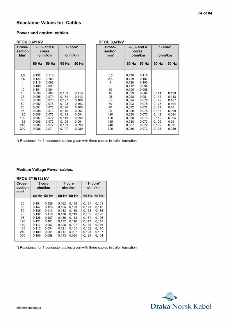
74 of 84
offshorecatalogue
Reactance Values for Cables
Power and control cables.
RFOU 0,6/1 kV BFOU 0,6/1kVCross-section
Mm²
2-, 3- and 4cores
ohm/km
60 Hz 50 Hz
1- core*
ohm/km
60 Hz 50 Hz
Cross-section
mm²
2-, 3- and 4cores
ohm/km
60 Hz 50 Hz
1- core*
ohm/km
60 Hz 50 Hz
1,5 0,132 0,110 1,5 0,138 0,1152,5 0,123 0,103 2,5 0,129 0,1074 0,115 0,096 4 0,120 0,1006 0,108 0,090 6 0,112 0,094
10 0,101 0,084 10 0,105 0,08816 0,096 0,080 0,139 0,116 16 0,099 0,082 0,144 0,12025 0,095 0,079 0,134 0,112 25 0,098 0,081 0,135 0,11335 0,092 0,076 0,127 0,106 35 0,094 0,078 0,129 0,10750 0,092 0,076 0,123 0,103 50 0,093 0,078 0,125 0,10470 0,091 0,075 0,120 0,100 70 0,092 0,077 0,121 0,10195 0,088 0,073 0,116 0,097 95 0,090 0,075 0,117 0,098
120 0,086 0,072 0,113 0,094 120 0,088 0,073 0,112 0,094150 0,087 0,072 0,110 0,092 150 0,088 0,073 0,112 0,094185 0,086 0,072 0,109 0,091 185 0,088 0,073 0,109 0,091240 0,086 0,072 0,109 0,090 240 0,087 0,072 0,109 0,091300 0,086 0,071 0,107 0,089 300 0,086 0,072 0,108 0,089
*) Reactance for 1-conductor cables given with three cables in trefoil formation
Medium Voltage Power cables.
RFOU 6/10(12) kVCross-sectionmm²
3 coreohm/km
60 Hz 50 Hz
4 coreohm/km
60 Hz 50 Hz
1- core*ohm/km
60 Hz 50 Hz
25 0,151 0,126 0,162 0,135 0,181 0,15135 0,147 0,123 0,155 0,129 0,173 0,14550 0,136 0,113 0,143 0,119 0,162 0,13570 0,132 0,110 0,136 0,119 0,155 0,12995 0,128 0,107 0,136 0,113 0,151 0,126
120 0,121 0,101 0,132 0,110 0,143 0,119150 0,117 0,097 0,128 0,107 0,139 0,116185 0,113 0,094 0,121 0,101 0,132 0,110240 0,109 0,091 0,117 0,097 0,128 0,107300 0,106 0,088 0,113 0,094 0,124 0,104
*) Reactance for 1-conductor cables given with three cables in trefoil formation
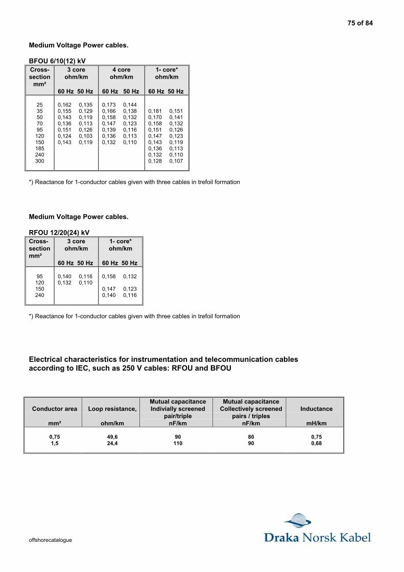
75 of 84
offshorecatalogue
Medium Voltage Power cables.
BFOU 6/10(12) kVCross-section
mm²
3 coreohm/km
60 Hz 50 Hz
4 coreohm/km
60 Hz 50 Hz
1- core*ohm/km
60 Hz 50 Hz
25 0,162 0,135 0,173 0,14435 0,155 0,129 0,166 0,138 0,181 0,15150 0,143 0,119 0,158 0,132 0,170 0,14170 0,136 0,113 0,147 0,123 0,158 0,13295 0,151 0,126 0,139 0,116 0,151 0,126
120 0,124 0,103 0,136 0,113 0,147 0,123150 0,143 0,119 0,132 0,110 0,143 0,119185 0,136 0,113240 0,132 0,110300 0,128 0,107
*) Reactance for 1-conductor cables given with three cables in trefoil formation
Medium Voltage Power cables.
RFOU 12/20(24) kVCross-sectionmm²
3 coreohm/km
60 Hz 50 Hz
1- core*ohm/km
60 Hz 50 Hz
95 0,140 0,116 0,158 0,132120 0,132 0,110150 0,147 0,123240 0,140 0,116
*) Reactance for 1-conductor cables given with three cables in trefoil formation
Electrical characteristics for instrumentation and telecommunication cablesaccording to IEC, such as 250 V cables: RFOU and BFOU
Conductor area
mm²
Loop resistance,
ohm/km
Mutual capacitanceIndivially screened
pair/triplenF/km
Mutual capacitanceCollectively screened
pairs / triplesnF/km
Inductance
mH/km
0,75 49,6 90 80 0,751,5 24,4 110 90 0,68
76 of 84
offshorecatalogue
Core colours for cables according to IEC
Please look at the actual page for each cable type.
Power and control cables for fixed installation, such as RFOU, BFOU, RU and BU 0,6/1kV
1-core : Grey (Off-white)2-cores : Grey (Off-white) -- Black3-cores : Grey (Off-white) -- Black -- Red4-cores : Grey (Off-white) -- Black -- Red -- Blue5-cores : Grey (Off-white) -- Black -- Red -- Blue -- Black
Above 5-cores : Black numbers on white base.Earth conductor : Yellow/green.
Medium Voltage cables for fixed installation, such as RFOU 6/10(12)kV, RFOU 12/20(24)kV andBFOU 6/10(12)kV
One core: Grey (Off-white) + black semi-conductive layer
Three cores: Grey (Off-white) + black semi-conductive layer identified by White-Black-Red threadsunder and over the metallic screen on each individual core.
Earth core: Yellow/green
Instrumentation and communication cables for fixed installation, such as RFOU, BFOU, RU and BU 250V
Pair : Black-Light BlueTriple : Black-Light Blue-Brown
Pairs/triples are numbered with numbered tape or by numbers printed directly on the insulated conductor.
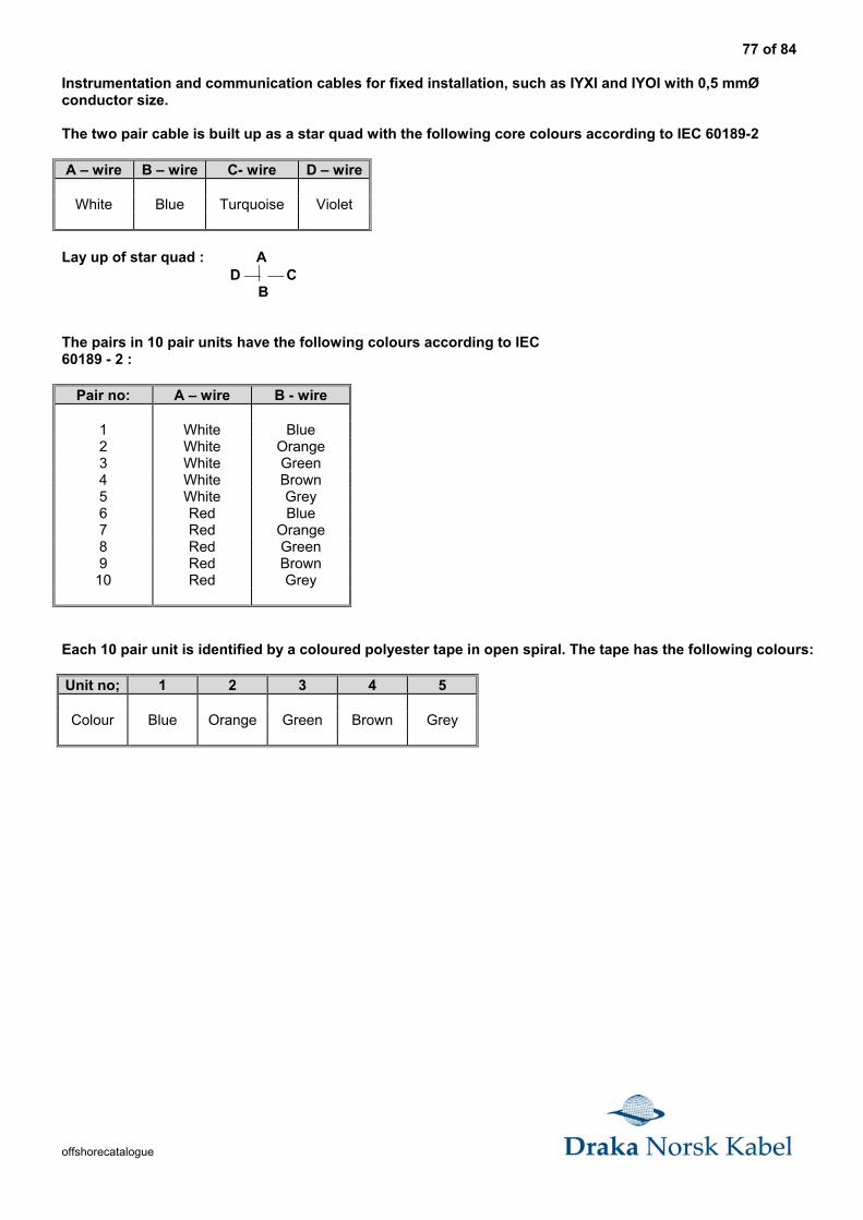
77 of 84
offshorecatalogue
Instrumentation and communication cables for fixed installation, such as IYXI and IYOI with 0,5 mmØconductor size.
The two pair cable is built up as a star quad with the following core colours according to IEC 60189-2
A – wire B – wire C- wire D – wire
White Blue Turquoise Violet
Lay up of star quad : A D C B
The pairs in 10 pair units have the following colours according to IEC60189 - 2 :
Pair no: A – wire B - wire
1 White Blue2 White Orange3 White Green4 White Brown5 White Grey6 Red Blue7 Red Orange8 Red Green9 Red Brown
10 Red Grey
Each 10 pair unit is identified by a coloured polyester tape in open spiral. The tape has the following colours:
Unit no; 1 2 3 4 5
Colour Blue Orange Green Brown Grey
78 of 84
offshorecatalogue
Material properties
Polymeric materials used in cables for ships and offshore
For 20 years Draka Norsk Kabel has been facing the same challenge :
The increasing severe performance criteria demands from our ship and offshore customers.
Elastomers are the major part of our cable construction.The insulation, bedding and sheathing have been developed through intensiveresearch and development to meet the offshore and ship industry's specific and stringentrequirements.
This information is not intended to give you details of the elastomers in use.For correct selection and application of materials our technical representatives will be pleased toprovide you with more complete information.
EP - rubber (EPDM)EPDM is a hydrocarbon rubber that combines electrical performance suitable for fire resistantoffshore cables with mechanical toughness and resistance to ozone, UV light and heat.It's wet electrical properties are unique.
Applications : Wire insulation Bedding compounds
Flame retardant halogen-free termoset compound (EVA)
EVA, ethylene vinyl acetate, is a multi-functional elastomer,which resists the combined deteriorating influences of heat, oil and weather.(In accordance with IEC 60092-359 type SHF2). For offshore applications, EVA can becompounded to produce high quality cable sheathing with low smoke and flame propagation, andwith no acid gas emission.
Applications : Cable sheathing on offshore oil platforms,ships, hotels and in rooms with expensiveequipment, which must not be subjected tocorrosion damage.
Low smoke , Flame retardant and Halogen-free Thermoplastic compounds , LSFR0H.
When PVC is not acceptable due to the problems clorine containing materialspresents in the event of a fire LSFR0H must be used.LSFR0H will not propagate a fire along a cable run, drip or give off black smoke.No acid gases will be released during a fire that can corrode and damage expensiveequipment.
Applications: Cable sheating forrooms with IT equipmenthigh - rise buldings (hotels)hospitalsTelephone exchangessubway systemsairportsand many others .
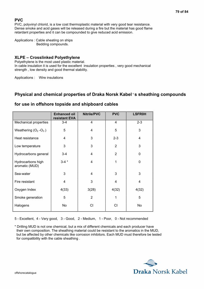
79 of 84
offshorecatalogue
PVCPVC, polyvinyl chlorid, is a low cost thermoplastic material with very good tear resistance.Dense smoke and acid gases will be released during a fire but the material has good flameretardant properties and it can be compounded to give reduced acid emission.
Applications : Cable sheating on ships Bedding compounds.
XLPE – Crosslinked PolyethylenePolyethylene is the most used plastic material.In cable insulation it is used for the excellent insulation properties , very good mechanicalstrength , low density and good thermal stability.
Applications : Wire insulations
Physical and chemical properties of Draka Norsk Kabel's sheathing compounds
for use in offshore topside and shipboard cables
Enhanced oilresistant EVA
Nitrile/PVC PVC LSFR0H
Mechanical properties 3-4 4 4 2-3
Weathering (O2 -O3 ) 5 4 5 3
Heat resistance 4 3 2-3 4
Low temperature 3 3 2 3
Hydrocarbons general 3-4 4 2 0
Hydrocarbons higharomatic (MUD)
3-4 * 4 1 0
Sea-water 3 4 3 3
Fire resistant 4 3 4 4
Oxygen Index 4(33) 3(28) 4(32) 4(32)
Smoke generation 5 2 1 5
Halogens No Cl CI No
5 - Excellent, 4 - Very good, 3 - Good, 2 - Medium, 1 - Poor, 0 - Not recommended
* Drilling MUD is not one chemical, but a mix of different chemicals and each producer have their own composition. The sheathing material could be resistant to the aromatics in the MUD, but be affected by other chemicals like corrosion inhibitors. Each MUD must therefore be tested for compatibility with the cable sheathing .
80 of 84
offshorecatalogue
Fire, flame, smoke and corrosion test methods
Cables' integrity during a fire
Fire resistanceDuring a fire it is vital that emergency circuits should continue to function.This could be communication circuits, emergency lights, alarms and fire pumps, etc.
On oil rigs and platforms and other confined areas this could be a matter of life and death.
Cables that will function in a fire ensuring circuit integrity
BFOU / BFCU / BU cables
This cable has Mica tape applied around the conductors, insulated with heat-resistant rubber covered by a bedding ofmineral-filled thermoplastic. This is followed by a metal braiding and an outer sheathing of a halogen-free thermosetcompound.
Test methodIEC 60331 750°C 3 hours.As an option we offer cables to 1000°C for 3 hours with an upgraded IEC 60331 test.
Flame propagation
Flame retardant cables must be self-extinguishing when the source of flames dies out.
Flame retardant cables with built-in self-extinguishing properties
These cables have sheathing and bedding with hydrated flame retardants that provide resistance to ignition and flamespread.
Test methods
IEC 60332 - 1IEC 60332 - 3, category A, B and C.
IEC 60332 - 3Category
Amount of combustible material inlitres per metre of cable ladder
Burning timeMinutes
A 7 40B 3,5 40C 1,5 20
Smoke risk to personnelSmoke evolution is of major significance in situations whereescape routes are limited in the event of fire.
Cables having exceptionally low smoke emissionAll offshore topside cables and fire resistant cables listed in this catalogue,have sheathing and insulation based on halogen-free materials.To minimise the risk of smoke and toxic gases, each component fromconductor tapes to outer sheath has been taken into consideration.
Test method3 m Cube Test for the measurement of smoke density.IEC 61034 - 2
81 of 84
offshorecatalogue
Damage to expensive equipment
Corrosion
Halogen-free cables will not cause corrosion to metals.
When halogen - containing cables burn, the gases generatedin combustion of the sheathing and insulation may cause corrosion.The secondary effects after a fire are often many times larger thanthe damages caused by the fire itself.
Test methodIEC 60754 - 1IEC 60754 - 2
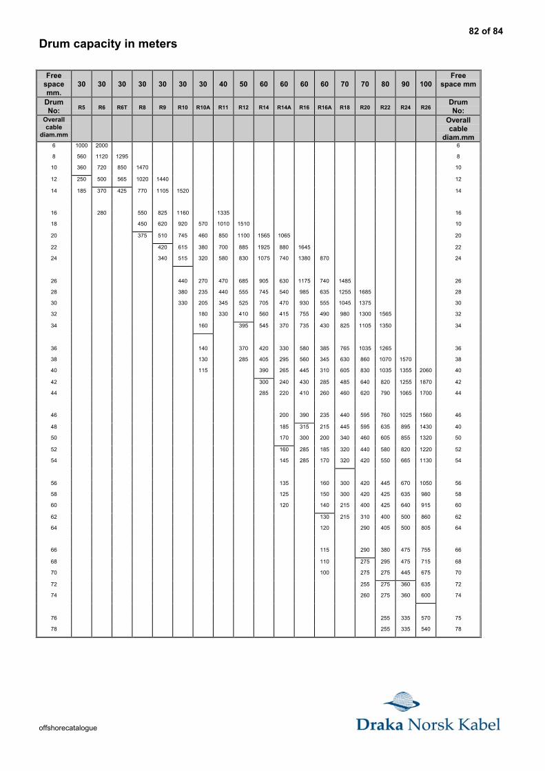
82 of 84
offshorecatalogue
Drum capacity in meters
Freespacemm.
30 30 30 30 30 30 30 40 50 60 60 60 60 70 70 80 90 100Free
space mm
DrumNo: R5 R6 R6T R8 R9 R10 R10A R11 R12 R14 R14A R16 R16A R18 R20 R22 R24 R26
DrumNo:
Overallcable
diam.mm
Overallcable
diam.mm6 1000 2000 6
8 560 1120 1295 8
10 360 720 850 1470 10
12 250 500 565 1020 1440 12
14 185 370 425 770 1105 1520 14
16 280 550 825 1160 1335 16
18 450 620 920 570 1010 1510 10
20 375 510 745 460 850 1100 1565 1065 20
22 420 615 380 700 885 1925 880 1645 22
24 340 515 320 580 830 1075 740 1380 870 24
26 440 270 470 685 905 630 1175 740 1485 26
28 380 235 440 555 745 540 985 635 1255 1685 28
30 330 205 345 525 705 470 930 555 1045 1375 30
32 180 330 410 560 415 755 490 980 1300 1565 32
34 160 395 545 370 735 430 825 1105 1350 34
36 140 370 420 330 580 385 765 1035 1265 36
38 130 285 405 295 560 345 630 860 1070 1570 38
40 115 390 265 445 310 605 830 1035 1355 2060 40
42 300 240 430 285 485 640 820 1255 1870 42
44 285 220 410 260 460 620 790 1065 1700 44
46 200 390 235 440 595 760 1025 1560 46
48 185 315 215 445 595 635 895 1430 40
50 170 300 200 340 460 605 855 1320 50
52 160 285 185 320 440 580 820 1220 52
54 145 285 170 320 420 550 665 1130 54
56 135 160 300 420 445 670 1050 56
58 125 150 300 420 425 635 980 58
60 120 140 215 400 425 640 915 60
62 130 215 310 400 500 860 62
64 120 290 405 500 805 64
66 115 290 380 475 755 66
68 110 275 295 475 715 68
70 100 275 275 445 675 70
72 255 275 360 635 72
74 260 275 360 600 74
76 255 335 570 75
78 255 335 540 78
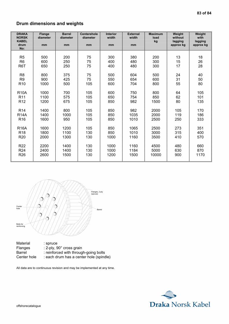
83 of 84
offshorecatalogue
Drum dimensions and weights
DRAKANORSKKABELdrumNo:
Flangediameter
mm
Barreldiameter
mm
Centereholediameter
mm
Interiorwidth
mm
Externalwidth
mm
Maximumloadkg
Weightwithoutlagging
approx kg
Weightwith
laggingapprox kg
R5 500 200 75 300 380 200 13 18R6 600 250 75 400 480 300 15 26
R6T 650 250 75 400 480 300 17 28
R8 800 375 75 500 604 500 24 40R9 900 425 75 550 654 600 31 50R10 1000 500 105 600 704 800 55 80
R10A 1000 700 105 600 750 800 64 105R11 1100 575 105 650 754 850 62 101R12 1200 675 105 850 982 1500 80 135
R14 1400 800 105 850 982 2000 105 170R14A 1400 1000 105 850 1035 2000 119 186R16 1600 950 105 850 1010 2500 250 333
R16A 1600 1200 105 850 1065 2500 273 351R18 1800 1100 130 850 1010 3000 315 400R20 2000 1300 130 1000 1160 3500 410 570
R22 2200 1400 130 1000 1160 4500 480 660R24 2400 1400 130 1000 1184 5000 630 870R26 2600 1500 130 1200 1500 10000 900 1170
Barrel
Flanges, 2-ply(spruce)
Centerhole
Bolts forreinforcing
Material : spruceFlanges : 2-ply, 90° cross grainBarrel : reinforced with through-going boltsCenter hole : each drum has a center hole (spindle)
All data are to continuous revision and may be implemented at any time.
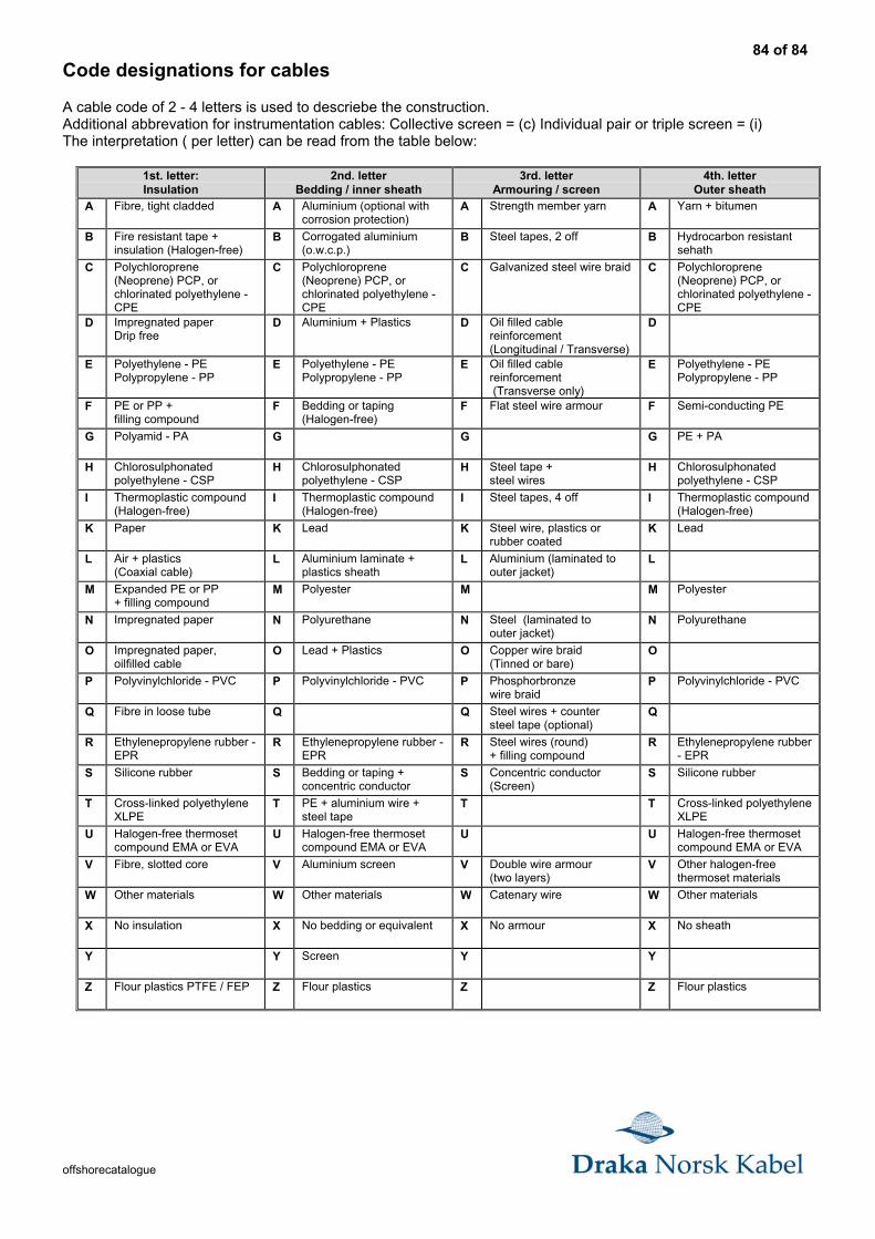
84 of 84
offshorecatalogue
Code designations for cables
A cable code of 2 - 4 letters is used to descriebe the construction.Additional abbrevation for instrumentation cables: Collective screen = (c) Individual pair or triple screen = (i)The interpretation ( per letter) can be read from the table below:
1st. letter:Insulation
2nd. letterBedding / inner sheath
3rd. letterArmouring / screen
4th. letterOuter sheath
A Fibre, tight cladded A Aluminium (optional withcorrosion protection)
A Strength member yarn A Yarn + bitumen
B Fire resistant tape +insulation (Halogen-free)
B Corrogated aluminium(o.w.c.p.)
B Steel tapes, 2 off B Hydrocarbon resistantsehath
C Polychloroprene(Neoprene) PCP, orchlorinated polyethylene -CPE
C Polychloroprene(Neoprene) PCP, orchlorinated polyethylene -CPE
C Galvanized steel wire braid C Polychloroprene(Neoprene) PCP, orchlorinated polyethylene -CPE
D Impregnated paperDrip free
D Aluminium + Plastics D Oil filled cablereinforcement(Longitudinal / Transverse)
D
E Polyethylene - PEPolypropylene - PP
E Polyethylene - PEPolypropylene - PP
E Oil filled cablereinforcement (Transverse only)
E Polyethylene - PEPolypropylene - PP
F PE or PP +filling compound
F Bedding or taping(Halogen-free)
F Flat steel wire armour F Semi-conducting PE
G Polyamid - PA G G G PE + PA
H Chlorosulphonatedpolyethylene - CSP
H Chlorosulphonatedpolyethylene - CSP
H Steel tape +steel wires
H Chlorosulphonatedpolyethylene - CSP
I Thermoplastic compound(Halogen-free)
I Thermoplastic compound(Halogen-free)
I Steel tapes, 4 off I Thermoplastic compound(Halogen-free)
K Paper K Lead K Steel wire, plastics orrubber coated
K Lead
L Air + plastics(Coaxial cable)
L Aluminium laminate +plastics sheath
L Aluminium (laminated toouter jacket)
L
M Expanded PE or PP+ filling compound
M Polyester M M Polyester
N Impregnated paper N Polyurethane N Steel (laminated toouter jacket)
N Polyurethane
O Impregnated paper,oilfilled cable
O Lead + Plastics O Copper wire braid(Tinned or bare)
O
P Polyvinylchloride - PVC P Polyvinylchloride - PVC P Phosphorbronzewire braid
P Polyvinylchloride - PVC
Q Fibre in loose tube Q Q Steel wires + countersteel tape (optional)
Q
R Ethylenepropylene rubber -EPR
R Ethylenepropylene rubber -EPR
R Steel wires (round)+ filling compound
R Ethylenepropylene rubber- EPR
S Silicone rubber S Bedding or taping +concentric conductor
S Concentric conductor(Screen)
S Silicone rubber
T Cross-linked polyethyleneXLPE
T PE + aluminium wire +steel tape
T T Cross-linked polyethyleneXLPE
U Halogen-free thermosetcompound EMA or EVA
U Halogen-free thermosetcompound EMA or EVA
U U Halogen-free thermosetcompound EMA or EVA
V Fibre, slotted core V Aluminium screen V Double wire armour(two layers)
V Other halogen-freethermoset materials
W Other materials W Other materials W Catenary wire W Other materials
X No insulation X No bedding or equivalent X No armour X No sheath
Y Y Screen Y Y
Z Flour plastics PTFE / FEP Z Flour plastics Z Z Flour plastics