Embed Size (px)
Citation preview
DRAFT: February 1, 2016
California Code of Regulations, Title 17, Division 3, Chapter 1, Subchapter 10 Climate Change, Article 4
PROPOSED REGULATION ORDER
Article Subarticle 13: Greenhouse Gas Emission Standards for
Crude Oil and Natural Gas Facilities § 9521095665. Purpose and Scope. The purpose of this article is to establish greenhouse gas emission standards for crude oil and natural gas facilities identified in section 9521195666. This article is designed to serve the purposes of the California Global Warming Solutions Act, AB 32, as codified in sections 38500-38599 of the Health and Safety Code. NOTE: Authority cited: Sections 38510, 38562, 39600, 39601 and 41511, Health and Safety Code. Reference: Sections 38560, 39600 and 41511, Health and Safety Code. § 9521195666. Applicability. (a) (a) General Applicability (1) This article applies to any person that owners or operateors of equipment and
components listed in section 95213 95668 located within California, including California waters, that is are associated with facilities in the sectors listed below, regardless of emissions level:
(A1) Onshore and offshore crude oil andor natural gas production; and, (2) processing, and cCrude oil, condensate, and produced water separation and
storage; and, (B3) Natural gas underground storage; and, (34) Natural gas gathering and boosting stations; and, (5) Natural gas processing plants; and, (C6) Natural gas transmission compressor stations.
(b) Owners and operators must ensure that their facilities, equipment, and components comply at all times with all requirements of this subarticle, including all of the standards and requirements identified in section 95668. Owners and operators are jointly and severally liable for compliance with this subarticle.
NOTE: Authority cited: Sections 38510, 38562, 39600, 39601 and 41511, Health and Safety Code. Reference: Sections 38560, 39600 and 41511, Health and Safety Code. § 9521295667. Definitions.
Page 1 of 67
DRAFT: February 1, 2016
(a) For the purposes of this article, the following definitions apply:
(1) “Air district or local air district” means the local Air Quality Management District or the local Air Pollution Control District.
(2) “Air Resources Board or ARB” means the California Air Resources Board. (3) "API gravity" means a scale used to reflect the specific gravity (SG) of a fluid
such as crude oil, condensate, produced water, or natural gas. The API gravity is calculated as [(141.5/SG) - 131.5], where SG is the specific gravity of the fluid at 60°F, and where API refers to the American Petroleum Institute.
(34) “Centrifugal compressor” means equipment that increases the pressure of
natural gas by centrifugal action. (45) “Centrifugal compressor seal” means a wet or dry seal around the compressor
shaft where the shaft exits the compressor case and that is designed to limit the amount of natural gas that can vent into the atmosphere.
(56) “Circulation tank” means a tank or portable tank used to circulate, store, or
expel hold liquids or solids from a crude oil or natural gas well during or following a well stimulation treatment.
(7) "Continuous bleed" means the continuous venting of natural gas from a gas
powered pneumatic device to the atmosphere. Continuous bleed pneumatic devices must vent continuously in order to operate.
(68) “Crude oil” means any of the naturally occurring liquids and semi-solids found in
rock formations composed of complex mixtures of hydrocarbons ranging from one to hundreds of carbon atoms in straight and branched chain rings.
(79) “Condensate” means hydrocarbon and or other liquid either produced or
separated from crude oil or natural gas during production and which condenses due to changes in pressure or temperature.
(810) “Component” means a valve, fitting, flange, threaded-connection, process
drain, stuffing box, pressure relief-vacuum valve, pipe, seal fluid system, diaphragm, hatch, sight-glass, meter, open-ended line, pneumatic device, pneumatic pump, centrifugal compressor wet seal, or a reciprocating compressor rod packing or seal on units with less than 500 rated horsepower.
(911) “Critical component” means any component that would require the
shutdown of a critical process unit if that component was shutdown or disabled. which would require the shutdown of a critical process unit if these components were shutdown.. These components must be identified by the owner or operator of the equipment and approved by the local air district.
Page 2 of 67
DRAFT: February 1, 2016
(12) "Critical process unit" means a process unit that must remain in service
because of its importance to the overall process that requires it to continue to operate, and has no equivalent equipment to replace it or cannot be bypassed, and it is technically infeasible to repair leaks from that process unit without shutting it down and opening the process unit to the atmosphere.
(13) “Crude oil and produced water separation and storage” means all activities
associated with theseparating, storing or holding of emulsion, crude oil, condensate, or produced water at facilities to which this subarticle applies.
(14) “Emissions” means the discharge of natural gas into the atmosphere. (15) “Emulsion” means any mixture of crude oil, condensate, or produced water with
varying quantities of natural gas entrained in the liquids. (1016) “Equipment” means any stationary or portable machinery, object, or
contrivance covered by this subarticle, as set out by sections 95211 95666 and 95213668 of this article, including vessels, circulation tanks, reciprocating and centrifugal compressors, pneumatic devices and pumps, production wells, components, or any combination thereof.
(11) “Emissions” means the release of greenhouse gases, volatile organic
compounds, toxic air contaminants, or other hydrocarbon gases into the atmosphere.
(12) “Emulsion” means any mixture of crude oil, condensate, produced water, and
varying amounts of natural gas. (1317) “Facility” means any building, structure, facility or installation to which this
subarticle applies and which has the potential to emits any air contaminantnatural gas directly or as a fugitive emission. Facilities include all “Building,” “structure,” “facility,” or “installation” includes all pollutant emitting activitiesbuildings, structures, or installations which: (1) Are under the same ownership or operation, or which are owned or
operated by entities which are under common control; (2) Belong to the same industrial grouping either by virtue of falling within the
same two-digit standard industrial classification code or by virtue of being part of a common industrial process, manufacturing process, or connected process involving a common raw material; and,
(3) Are located on one or more contiguous or adjacent properties.
Page 3 of 67
DRAFT: February 1, 2016
(1418) “Flash or flashing” means a process during which gas entrained in emissions that vaporize from crude oil, condensate, or produced water under pressure is released when the liquids are subject to a decrease in pressure or increase in temperature, such as when the liquids are transferred from an underground reservoir to the earth’s surface.
(1519) “Flash analysis testing” means the determination of emissions from crude
oil, condensate, and produced water by using sampling and laboratory procedures used for measuring the volume and composition of gases compressed released into from the liquids, including the molecular weight of the total gaseous sample, the weight percent of individual compounds, and a gas-oil or gas-water ratio.
(20) "Inaccessible component" means any component located over fifteen feet
above ground when access is required from the ground; or any component located over six (6) feet away from a platform when access is required from the platform.
(21) "Intermittent bleed" means the intermittent venting of natural gas from a gas
powered pneumatic device to the atmosphere. Intermittent bleed pneumatic devices may vent all or a portion of their supply gas when control action is necessary but do not vent continuously.
(1622) “Fugitive lLeak or fugitive leakemissions” means the unintended or
incidental leakunintentional release of emissions at a rate greater than or equal to the leak thresholds specified into the atmospherein this article.
(17) "Inaccessible component" means any component located over fifteen feet
above ground when access is required from the ground; or any component located over six (6) feet away from a platform when access is required from the platform.
(1823) “Leak detection and repair or LDAR” means the inspection of components
to detect fugitive leaks of total hydrocarbons emissions and the repair of components with leaks above an allowable leakspecified standards within a specified timeframes.
(1924) “Liquids unloading” means an activity conducted with the use of
pressurized the venting of natural gas from a natural gas production well to remove liquids that accumulate at the bottom of the a natural gas well and obstruct gas flow.
(25) "Minimize" means tightening, adjusting, or replacing components or equipment
for the purpose of stopping or reducing leaks below the lowest leak threshold specified in this subarticle.
Page 4 of 67
DRAFT: February 1, 2016
(20) “Major leak” means the detection of total gaseous hydrocarbons in excess of 10,000 ppmv as methane above background measured using EPA Method 21 (40
CFR 60, Appendix A). (21) “Major leak over 50,000 ppmv” means the detection of total gaseous
hydrocarbons in excess of 50,000 ppmv as methane above background measured using EPA Method 21 (40 CFR 60, Appendix A).
(22) “Minor leak” means the detection of total gaseous hydrocarbons in excess of 1,000 ppmv as methane above background measured using EPA Method 21 (40
CFR 60, Appendix A). (2326) “Natural gas” means a naturally occurring mixture or process derivative of
hydrocarbon and non-hydrocarbon gases. , of which iIts constituents include the greenhouse gases methane, and carbon dioxide, and as well as heavier hydrocarbons. Natural gas may be field quality (which varies widely) or pipeline quality.
(27) "Natural gas gathering and boosting station" means all equipment and
components located within a facility fence line associated with moving natural gas to a processing plant or natural gas transmission pipeline.
(28) “Natural gas processing plant” means a plant used for the separation of natural
gas liquids (NGLs) or non-methane gases from produced natural gas, or the separation of NGLs into one or more component mixtures.
(24289) “Natural gas transmission compressor station” means all equipment and
components located within a facility fence line associated with moving natural gas from production fields or natural gas processing plants through natural gas transmission pipelines.
(2930) "Natural gas transmission pipeline" means a Federal Energy Regulatory
Commission rate-regulated Interstate pipeline, a state rate-regulated Intrastate pipeline, or a pipeline that falls under the “Hinshaw Exemption” as referenced in section 1(c) of the Natural Gas Act, 15 U.S.C. 717-717z (19942015).
(231) “Natural gas underground storage” means all equipment and components
associated with the subsurface storage of natural gas in depleted crude oil or natural gas reservoirs or salt dome caverns.
(2632) “Offshore” means all marine waters located within the boundaries of the
State of California. (2733) “Onshore” means all lands located within the boundaries of the State of
California.
Page 5 of 67
DRAFT: February 1, 2016
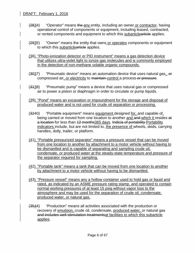
(2834) “Operator” means the any entity, including an owner or contractor, having operational control of components or equipment, including leased, contracted, or rented components and equipment to which this subarticlearticle applies.
(2935) “Owner” means the entity that owns or operates components or equipment
to which this subarticlearticle applies.
(36) "Photo-ionization detector or PID instrument" means a gas detection device that utilizes ultra-violet light to ionize gas molecules and is commonly employed in the detection of non-methane volatile organic compounds.
(3037) “Pneumatic device” means an automation device that uses natural gas, or
compressed air, or electricity to maintain control a process or pressure. (3138) “Pneumatic pump” means a device that uses natural gas or compressed
air to power a piston or diaphragm in order to circulate or pump liquids. (39) "Pond" means an excavation or impoundment for the storage and disposal of
produced water and is not used for crude oil separation or processing. (3240) “Portable equipment” means equipment designed for, and capable of,
being carried or moved from one location to another and and which it resides at a location for less than 12 months365 days. Indicia of portability Portability indicators include, but are not limited to, the presence of wheels, skids, carrying handles, dolly, trailer, or platform.
(41) "Portable pressurized separator" means a pressure vessel that can be moved
from one location to another by attachment to a motor vehicle without having to be dismantled and is capable of separating and sampling crude oil, condensate, or produced water at the steady-state temperature and pressure of the separator required for sampling.
(42) "Portable tank" means a tank that can be moved from one location to another
by attachment to a motor vehicle without having to be dismantled. (43) "Pressure vessel" means any a hollow container used to hold gas or liquid and
rated, as indicated by an ASME pressure rating stamp, and operated to contain normal working pressures of at least 15 psig without vapor loss to the atmosphere and may be used for the separation of crude oil, condensate, produced water, or natural gas.
(3544) “Production” means all activities associated with the production or
recovery of emulsion, crude oil, condensate, produced water, or natural gas and includes well stimulation treatmentsat facilities to which this subarticle applies.
Page 6 of 67
DRAFT: February 1, 2016
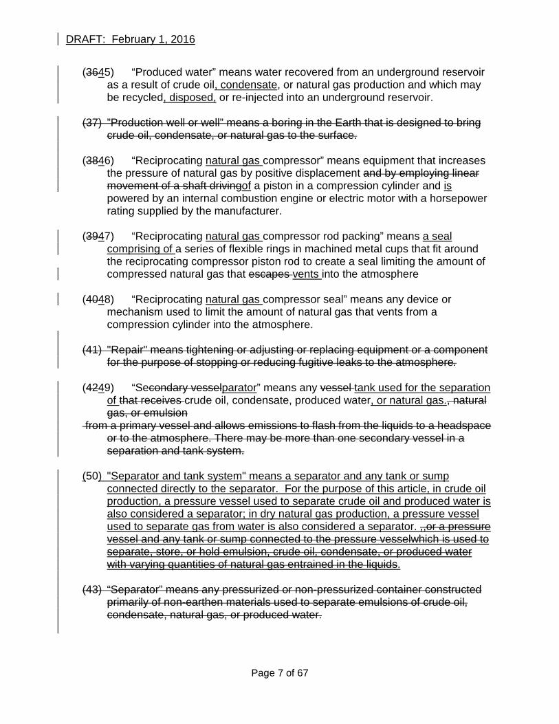
(3645) “Produced water” means water recovered from an underground reservoir as a result of crude oil, condensate, or natural gas production and which may be recycled, disposed, or re-injected into an underground reservoir.
(37) ”Production well or well” means a boring in the Earth that is designed to bring
crude oil, condensate, or natural gas to the surface. (3846) “Reciprocating natural gas compressor” means equipment that increases
the pressure of natural gas by positive displacement and by employing linear movement of a shaft drivingof a piston in a compression cylinder and is powered by an internal combustion engine or electric motor with a horsepower rating supplied by the manufacturer.
(3947) “Reciprocating natural gas compressor rod packing” means a seal
comprising of a series of flexible rings in machined metal cups that fit around the reciprocating compressor piston rod to create a seal limiting the amount of compressed natural gas that escapes vents into the atmosphere
(4048) “Reciprocating natural gas compressor seal” means any device or
mechanism used to limit the amount of natural gas that vents from a compression cylinder into the atmosphere.
(41) "Repair" means tightening or adjusting or replacing equipment or a component
for the purpose of stopping or reducing fugitive leaks to the atmosphere. (4249) “Secondary vesselparator” means any vessel tank used for the separation
of that receives crude oil, condensate, produced water, or natural gas., natural gas, or emulsion
from a primary vessel and allows emissions to flash from the liquids to a headspace or to the atmosphere. There may be more than one secondary vessel in a separation and tank system.
(50) "Separator and tank system" means a separator and any tank or sump
connected directly to the separator. For the purpose of this article, in crude oil production, a pressure vessel used to separate crude oil and produced water is also considered a separator; in dry natural gas production, a pressure vessel used to separate gas from water is also considered a separator. ,,or a pressure vessel and any tank or sump connected to the pressure vesselwhich is used to separate, store, or hold emulsion, crude oil, condensate, or produced water with varying quantities of natural gas entrained in the liquids.
(43) “Separator” means any pressurized or non-pressurized container constructed
primarily of non-earthen materials used to separate emulsions of crude oil, condensate, natural gas, or produced water.
Page 7 of 67
DRAFT: February 1, 2016
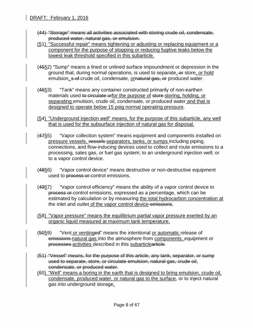
(44) “Storage” means all activities associated with storing crude oil, condensate, produced water, natural gas, or emulsion.
(51) "Successful repair" means tightening or adjusting or replacing equipment or a component for the purpose of stopping or reducing fugitive leaks below the lowest leak threshold specified in this subarticle.
(4552) “Sump” means a lined or unlined surface impoundment or depression in the
ground that, during normal operations, is used to separate, or store, or hold emulsion, s of crude oil, condensate, ornatural gas, or produced water.
(4653) “Tank” means any container constructed primarily of non-earthen
materials used to circulate orfor the purpose of store storing, holding, or separating emulsion, crude oil, condensate, or produced water and that is designed to operate below 15 psig normal operating pressure.
(54) "Underground injection well" means, for the purpose of this subarticle, any well
that is used for the subsurface injection of natural gas for disposal. (4755) “Vapor collection system” means equipment and components installed on
pressure vessels, vessels separators, tanks, or sumps including piping, connections, and flow-inducing devices used to collect and route emissions to a processing, sales gas, or fuel gas system; to an underground injection well; or to a vapor control device.
(4856) “Vapor control device” means destructive or non-destructive equipment
used to process or control emissions. (4957) “Vapor control efficiency” means the ability of a vapor control device to
process or control emissions, expressed as a percentage, which can be estimated by calculation or by measuring the total hydrocarbon concentration at the inlet and outlet of the vapor control device emissions.
(58) "Vapor pressure" means the equilibrium partial vapor pressure exerted by an
organic liquid measured at maximum tank temperature. (5059) “Vent or ventinged” means the intentional or automatic release of
emissions natural gas into the atmosphere from components, equipment or processes activities described in this subarticlearticle.
(51) “Vessel” means, for the purpose of this article, any tank, separator, or sump
used to separate, store, or circulate emulsion, natural gas, crude oil, condensate, or produced water.
(60) ”Well” means a boring in the earth that is designed to bring emulsion, crude oil, condensate, produced water, or natural gas to the surface, or to inject natural gas into underground storage.
Page 8 of 67
DRAFT: February 1, 2016
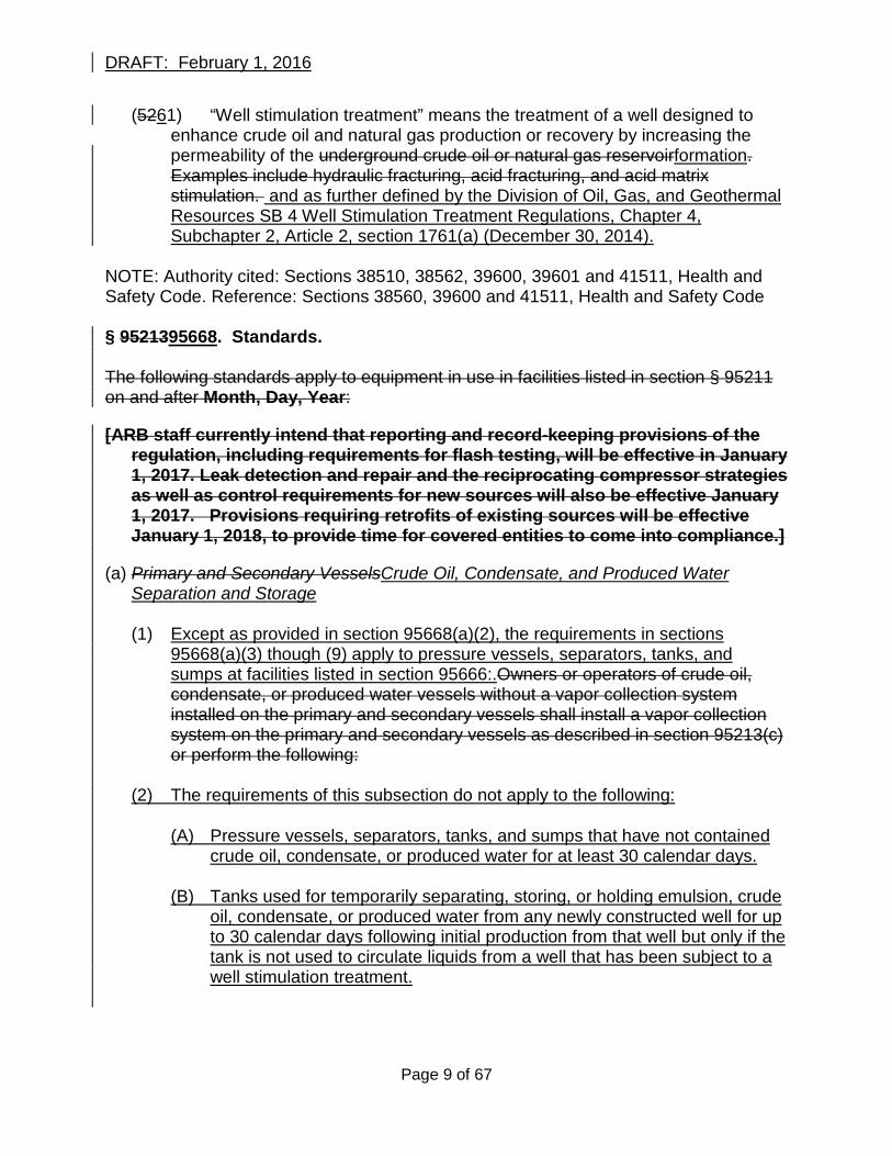
(5261) “Well stimulation treatment” means the treatment of a well designed to enhance crude oil and natural gas production or recovery by increasing the permeability of the underground crude oil or natural gas reservoirformation. Examples include hydraulic fracturing, acid fracturing, and acid matrix stimulation. and as further defined by the Division of Oil, Gas, and Geothermal Resources SB 4 Well Stimulation Treatment Regulations, Chapter 4, Subchapter 2, Article 2, section 1761(a) (December 30, 2014).
NOTE: Authority cited: Sections 38510, 38562, 39600, 39601 and 41511, Health and Safety Code. Reference: Sections 38560, 39600 and 41511, Health and Safety Code § 9521395668. Standards. The following standards apply to equipment in use in facilities listed in section § 95211 on and after Month, Day, Year: [ARB staff currently intend that reporting and record-keeping provisions of the
regulation, including requirements for flash testing, will be effective in January 1, 2017. Leak detection and repair and the reciprocating compressor strategies as well as control requirements for new sources will also be effective January 1, 2017. Provisions requiring retrofits of existing sources will be effective January 1, 2018, to provide time for covered entities to come into compliance.]
(a) Primary and Secondary VesselsCrude Oil, Condensate, and Produced Water
Separation and Storage
(1) Except as provided in section 95668(a)(2), the requirements in sections 95668(a)(3) though (9) apply to pressure vessels, separators, tanks, and sumps at facilities listed in section 95666:.Owners or operators of crude oil, condensate, or produced water vessels without a vapor collection system installed on the primary and secondary vessels shall install a vapor collection system on the primary and secondary vessels as described in section 95213(c) or perform the following:
(2) The requirements of this subsection do not apply to the following:
(A) Pressure vessels, separators, tanks, and sumps that have not contained crude oil, condensate, or produced water for at least 30 calendar days.
(B) Tanks used for temporarily separating, storing, or holding emulsion, crude oil, condensate, or produced water from any newly constructed well for up to 30 calendar days following initial production from that well but only if the tank is not used to circulate liquids from a well that has been subject to a well stimulation treatment.
Page 9 of 67
DRAFT: February 1, 2016
(3) Beginning January 1, 2017, pressure vessels not already subject to a district leak detection and repair program shall comply with the leak detection and repair requirements specified in section 95669.
(4) Beginning January 1, 2017 and by no later than September 1, 2017, owners or
operators of new and existing separator and tank systems which are not controlled for emissions with the use of a vapor collection system shall conduct annual flash analysis testing of the crude oil, condensate, or produced water as described below.
(A) Conduct annual flash analysis testing of the crude oil, condensate, and
produced water separated or stored by the primary and secondary vessels to determine the annual methane emission rate as follows:
1.(A) Flash Conduct flash analysis testing shall be conducted in accordance
with the ARB Test Procedure for Determining Annual Flash Emission Rate of Methane from Crude Oil, Condensate, and Produced Water as described in Appendix AC. 2. Flash analysis testing is required at each primary vessel. Additional
flash analysis testing may be conducted and the results averaged in order to determine representative testing.
3.(B) Sum the annual emission rates offlash analysis testing results for methane
as determined in section 95213(a)(1)(B)1 for the crude oil, condensate, and produced water.
4.(C) Report the resultsMaintain a record of flash analysis testing as described specified in section 95215(a)1671 and report the results to ARB as specified in section 95672.
5.(D) Owners or operators must dDemonstrate that the results of the flash
analysis testing are representative of the liquids processed by the primary and secondary vesselscrude oil, condensate, and produced water processed or stored in the separator and tank system. The ARB Executive Officer or the local air district may request additional flash analysis testing or information in the event that the test results reported do not reflect representative results of similar systems.
(B5) OBeginning January 1, 2018, owners or operators of separator and tank
systems primary and secondary vessels with a measured annual flash emission rate greater than 10 metric tons per year of methane as determined in section 95213(a)(1)(B)(3) shall control the primary and secondary vesselsemissions from the separator and any tank system or sump connected to the separator, or any tank or sump connected to the pressure vessel, as follows:
Page 10 of 67
DRAFT: February 1, 2016
1. Vessels shall be equipped with leak free solid roofs and hatches; and, 2. Vessels shall be controlled with use of with the use of a vapor collection system
as described specified in section 9521395668(cc).; or, (6) Beginning January 1, 2018, separators, tanks, and covered sumps subject to
the vapor collection system requirements specified in section 95668(a)(6) shall comply with the leak detection and repair requirements specified in section 95669.
(C7) OOwners or operators of primary and secondary vessels without a vapor
collection system and a measuredseparator and tanks systems with a flash annual emission rate less than or equal to 10 metric tons per year of methane as determined in section 95213(a)(1)(B)(3) shall conduct flash analysis testing and reporting annually. , unless the owner or operator can demonstrate that the annual emission rate has not changed using three (3) consecutive years of test results; and,
If the owner or operator can successfully demonstrate to ARB or the local air
district that the results of flash analysis testing have not changedare less than or equal to 10 metric tons per year of methane using three consecutive years of test dataresults the owner or operator may reduce the frequency of flash analysis testing and reporting may be reduced to once every five (5) years thereafter; and,.
(8) Flash analysis testing, record keeping, and reporting shall be conducted within
one calendar year of adding a new well to the separator and tank system since the time of previous flash analysis testing.
2.(9) Flash emissions shall be recalculated Flash analysis testing and reporting shall
be if the annual conducted at any time the annual crude oil, condensate, or natural gasproduced water throughput of the primary and secondary vessels increases throughput increases by more than ten (10)10 percent since the time of the most recent flash analysis testing and reporting.previous flash analysis testing provided that the increase in throughput is not a result of adding a new well to the separator and tank system which requires additional flash analysis testing as specified in section 95668(a)(8).
(A) The owner or operator shall maintain and make available upon request by
the ARB Executive Officer a record of the revised flash emission calculation.
(bb) Circulation Tanks for Well Stimulation Treatments
(1) Beginning January 1, 2018, Circulation circulation tanks used in conjunction
with well stimulation treatments used at facilities listed in section 95666 shall be
Page 11 of 67
DRAFT: February 1, 2016
controlled for emissions of natural gas according to meet one of the following requirementsmethods:
(A) Control emission vapors fromThe circulated liquids shall be controlled for
emissions of natural gas prior to entering the circulation tank using a pressure vessel or separator and a vapor collection system as specified in section 95668(c)prior to the circulation tank and the circulation tank shall be covered and comply with the leak detection and repair requirements specified in section 95669using a vapor collection and control system as described in section 95213(c); or,
(B) Circulation tanks shall be equipped with leak free solid roofs and hatches;
and, (CB) Circulation tanks shall be covered and controlled for emissions of natural
gas using s shall be controlled with use of a vapor collection system and control system as described in section 9521395668(cc) and the tank shall comply with the leak detection and repair requirements specified in section 95669.
(c) Vapor Collection Systems and Vapor Control Devices
(1) Beginning January 1, 2018, The the following requirements apply to equipment at facilities listed in section 95666 that are subject to the vapor collection system and control device requirements specified in this subarticle: primary and secondary vessels and to circulation tanks for well stimulation treatments:
(12) The Unless section 95668(c)(3) applies, the vapor collection system shall direct
the collected vapors to one of the following types of existing equipment or processes installed at the operation:
(A) Existing sSales gas system; or, (B) Existing fFuel gas system; or, (C) Underground Existing underground injection well not currently under
review by the Division of Oil and Gas and Geothermal Resources.
(23) If the owner or operator can demonstrate no existing sales gas system, fuel gas system, or underground injection well to the satisfaction of the local air district that the collected vapors cannot be controlled according to one of the methods describedspecified in section 9521395668(c)(12) is available exists at the facility or it is not technically feasible to utilize, , the owner or operator must control the collected vapors as follows:
(A) For facilities without an existing vapor control device installed at the facility, the owner or operator must install a new vapor control device as specified in section 95668(c)(4); or,
Page 12 of 67
DRAFT: February 1, 2016
(B) For facilities currently operating a vapor control device and which are required to control additional vapors as a result of this subarticle, the owner or operator must replace the existing vapor control device with a new vapor control device as specified in section 95668(c)(4) to control all of the collected vapors.
the vapor collection system shall direct the collected vapors to an existing vapor control device provided that any added vapors do not exceed the device’s permitted emission limits.
(34) The Any vapor control device required in section 95668(c)(3) must meet the
following requirements:
(A) If the vapor control device is to be installed in a region classified as in attainment with all state or federal ambient air quality standards, the vapor control device must achieve at least 95% vapor control efficiency of total emissions and must meet all applicable federal, state, and local air district requirements; or,
(B) If the vapor control device is to be installed in a region classified as
non-attainment with, or which has not been classified as in attainment of, all state and federal ambient air quality standards, the owner or operator must install one of the following devices that meets all applicable federal, state, and local air district requirements: owner or operator must demonstrate to the satisfaction of the local air district that the collected vapors cannot be controlled according to one of the methods described in section 95213(c)(1) or 95213(c)(2) if they wish to use any of the methods described in section 95213(c)(4).
(4) If the owner or operator can successfully demonstrate that the collected
vapors cannot be controlled according to one of the methods described in 95213(c)(1) or 95213(c)(2), the owner or operator must apply for local air district approval to install one of the following:
(A) A vapor control device with at least 95% vapor control efficiency and which meets all applicable federal, state, and local air district requirements; or,
(B) If the system is located in an area classified as nonattainment with state or
federal ozone standards, the owner or operator must apply for local air district approval to install one of the following types of equipment that meets all applicable federal, state, and local air district requirements: 1. A non-destructive vapor control device that achieves at least 95%
vapor control efficiency of total emissions and does not result in emissions of nitrogen oxides (NOx) above local air district requirements; or,
Page 13 of 67
DRAFT: February 1, 2016
2. A vapor control device that that achieves at least 95% vapor control efficiency of total emissions and does not generate more than 15 parts per million volume (ppmv) NOx when measured at 3% oxygen.
does not require supplemental fuel gas to operate or result in emissions of NOx above local air district requirements.
(5) If it is not technically feasible to control the collected vapors cannot be
controlled as specified in section 95668(c)(2) through (4), then that the equipment subject to the vapor collection and control requirements specified in this subarticle may not be used or installed and must be removed from service by January 1, 2018.
(56) Vapor collection systems and control devices are allowed up to 14 30 calendar
days per year for equipment breakdowns ormalfunctions or maintenance provided that the local air districtARB is notified within one four (41) hours of the discovery of a system malfunction or if the system is intended to be taken out of service for scheduled maintenance. A time extension to make repairsperform maintenance not to exceed 14 calendar days may be granted by the local air district the ARB Executive Officer. The owner or operator is responsible for maintaining a record of tracking the number of calendar days per calendar year that the vapor collection system or vapor control device is out of service and must shall provide a record of such activity at the request of the ARB Executive Officer.the local air district.
(A) If an alternate vapor control device compliant with this section is installed
prior to conducting maintenance and the vapor collection and control system continues to collect and control vapors during the maintenance operation, the event does not count towards the 30 calendar day limit.
(6B) Vapor collection system and control device shutdowns that result from
utility power outages or emergencies are not subject to enforcement action provided the system equipment resumes normal operation as soon as normal utility power is restored. Vapor collection system and control device shutdowns that result from utility power outages do not count towards the 30 calendar day limit for maintenance and ARB notification is not required.
(d) Reciprocating Natural Gas Compressors at or Below 500 Rated
Horsepower (1) Each compressor shall collect the rod packing or seal vent gas with a
vapor collection system and route the collected gas to an existing sales gas system, fuel gas system, or vapor control device; or,
(2) Each compressor shall provide a clearly identified access port for making
rod packing or seal vent emission measurements; and,
Page 14 of 67
DRAFT: February 1, 2016
(3) Compressor rod packing or seal vents shall be measured quarterly for
total hydrocarbon concentration in units of parts per million volume (ppmv) calibrated as methane in accordance with EPA Reference Method 21 (40 CFR 60, Appendix A); and,
(4) Compressor rod packing or seal vents with a measured total hydrocarbon
concentration above the following standards shall be repaired within the time period specified unless a more stringent leak concentration or more stringent repair time period is required by the local air district:
(A) Rod packing or seal vents with a measured total hydrocarbon
concentration above 1,000 ppmv but below 10,000 ppmv shall be successfully repaired or the unit removed from service within seven (7) calendar days. A time extension not to exceed seven (7) calendar days may be granted by ARB or the local air district.
(B) Rod packing or seal vents with a measured total hydrocarbon
concentration above 10,000 ppmv shall be successfully repaired or the unit removed from service within three (3) calendar days. A time extension not to exceed two (2) calendar days may be granted by ARB or the local air district.
(C) Rod packing or seal vents with a measured total hydrocarbon
concentration above 50,000 ppmv shall be successfully repaired or removed from service within two (2) calendar days.
(ed) Reciprocating Natural Gas Compressors over 500 Rated Horsepower
(1) The following requirements apply to reciprocating natural gas compressors at crude oil or natural gas production facilities listed in section 95666 which are not covered under section 95668(d)(2):
(A) Beginning January 1, 2017, components on driver engines and
compressors shall comply with the leak detection and repair requirements specified in section 95669.
(B) Beginning January 1, 2017, for any compressors without a vapor
collection system used to control the rod packing or seal vent gas, the rod packing or seal shall comply with the leak detection and repair requirements specified in section 95669; and,
(C) The owner or operator shall maintain a record of the rod packing or seal
leak concentration measurement as specified in Appendix A, Table 5. (D) A reciprocating natural gas compressor with a rod packing or seal leak
concentration measured above the minimum standard specified in section 95669 and which has been approved by the ARB Executive Officer as a critical component as specified in section 95670, shall be
Page 15 of 67
DRAFT: February 1, 2016
successfully repaired by the end of the next process shutdown or within 180 calendar days from the date of the initial leak concentration measurement, whichever is sooner.
(2) The following requirements apply to reciprocating natural gas compressors at
natural gas gathering and boosting stations, processing plants, transmission compressor stations, and underground natural gas storage facilities listed in section 95666 and which are not covered under section 95668(d)(1):
(A) Beginning January 1, 2017, components on driver engines and
compressors shall comply with the leak detection and repair requirements specified in section 95669.
(B) Each Beginning January 1, 2017, any compressor shall collect the rod
packing or seal vent gas with a vapor collection system and route the collected gas to an existing sales gas system, fuel gas system, or vapor control device; or,
(2) Each compressor without a vapor collection system used to control the rod
packing or seal vent gas shall be equipped with a meter or instrumentation that can measure the rod packing or seal emissions flow rate; or,
(C) The compressor shall be equipped with ashall provide a clearly identified
access port installed in the rod packing or seal vent stack at a height of no more than six (6) feet above ground level for making individual or combined rod packing or seal emission flow rate measurements; and,
(3D) Each individual compressorThe rod packing or seal emissions flow rate
shall be measured annually during normal operation to determine the rod packing or seal emission flow rate determined by direct measurement (high volume sampling, bagging, calibrated flow measuring instrument) while the compressor is running at normal operating temperature.
(4E) Beginning January 1, 2018, aAn individual compressor with a rod packing
or seal with a measured with a measured emission flow rate greater than two (2) standard cubic feet per minute (scfm), or a combined rod packing or seal emission flow rate greater than the number of compression cylinders multiplied by two (2) scfm, shall bebe successfully repaired or the unit removed from service replaced within 14 30 calendar days from the date of the initial emission flow rate measurement.unless a more stringent flow rate or more stringent repair time is required by the local air district. A time extension not to exceed 14 calendar days may be granted by ARB or the local air district.
(F) A reciprocating natural gas compressor with a rod packing or seal
emission flow rate measured above the standard specified in
Page 16 of 67
DRAFT: February 1, 2016
section 95688(d)(2)(E) and which has been approved by the ARB Executive Officer as a critical component as specified in section 95670, shall be successfully repaired by the end of the next process shutdown or within 180 days from the date of the initial flow rate measurement, whichever is sooner.
(fe) Centrifugal Natural Gas Compressors with Wet Seals
(1) The following requirements apply to centrifugal natural gas compressors with wet seals at facilities listed in section 95666:
(2) (1) Centrifugal natural gas compressor seal vents shall be controlled for
vented emissions according to one of the following methods: (A) Use a dry seal system; or,Beginning January 1, 2017, components on driver
engines and compressors shall comply with the leak detection and repair requirements specified in section 95669.
(3) Beginning January 1, 2017, any compressor without a vapor collection system used to control the wet seal vent gas shall be equipped with a meter or instrumentation that can measure the equipped with a meter or instrumentation that can measure the rod packing vent gas wet seal emissions flow rate; or
(4) The compressor shall be equipped with a clearly identified access port installed
in the wet seal vent stack at a height of no more than six (6) feet above ground levelwhich is accessible at ground level for making wet seal emission flow rate measurements; and,
(5) The wet seal emissions flow rate shall be measured annually by direct
measurement (high volume sampling, bagging, calibrated flow measuring instrument) while the compressor is running at normal operating temperature.
(6) Beginning January 1, 2018, a compressor with a wet seal emission flow rate
greater than three (3) scfm or a combined wet seal emission flow rate greater than the number of wet seals multiplied by three (3) scfm a shall control the wet seal emission vent gas with the use of a vapor collection system as specified in section 95668(c); or,(B) Collect the wet seal vent gas with a vapor collection system and route the collected gas to an existing sales gas system, fuel gas system, or vapor control device.
(7) Minimize the wet seal emission flow rate within 30 calendar days from the date
of the initial emission flow rate measurement and replace the wet seal with a dry seal by no later than January 1, 2020.
(8) A centrifugal natural gas compressor with a wet seal emission flow rate measured above the standard specified in section 95668(e)(6) and which has
Page 17 of 67
DRAFT: February 1, 2016
been approved by the ARB Executive Officer as a critical component as specified in section 95670, shall be successfully repaired by the end of the next process shutdown or within 180 days from the date of the initial flow rate measurement, whichever is sooner.
(gf) Natural Gas Powered Pneumatic Devices and Pumps
(1) Except as provided in section 95668(f)(2), the requirements in sections 95668(f)(3) through (6) apply to natural gas powered pneumatic devices and pumps at facilities listed in section 95666:
(2) A natural gas powered pneumatic device installed prior to January 1, 2015 may
be used provided it meets all of the following requirements:
(A) The device does not vent natural gas at a rate greater than 6 standard cubic feet per hour (scfh); and,
(B) The device is clearly marked with a permanent tag that identifies the vent
rate as less than or equal to 6 scfh; and, (C) The device is tested during each inspection period as specified in section
95669 by using a direct measurement method (high volume sampling, bagging, calibrated flow measuring instrument); and,
(D) A device with a measured emissions flow rate greater than 6 scfh shall be
repaired or replaced within 14 calendar days from the date of the initial emission flow rate measurement.
(13) Beginning January 1, 2018, Pneumatic devices; pneumatic devices that are
designed to continuously vent natural gas during normal operation shall not vent natural gas to the atmosphere and shall comply with the leak detection and repair requirements specified in section 95669.. Alternatively, they must meet one of the following requirements:
(A) Collect the vented natural gas with a vapor collection system and route the
collected gas to an existing sales gas system, fuel gas system, or vapor control device; or,
(B) Use compressed air to operate.
(24) Beginning January 1, 2018, iIntermittent leak bleed pneumatic devices that are
designed to vent natural gas only when actuated shall not leak when shall not vent natural gas when not actuating idledetermined by testing the device when not actuating in accordance with the leak detection and repair requirements specified in section 95669.
Page 18 of 67
DRAFT: February 1, 2016
(35) Beginning January 1, 2018, pPneumatic pumps shall not vent natural gas to the atmosphere and shall comply with the leak detection and repair requirements specified in section 95669.shall meet one the following requirements:
(6) Beginning January 1, 2018, pneumatic devices and pumps shall be retrofitted or replaced to prevent natural gas from venting to the atmosphere or shall be controlled according to one of the following methods:
(A)(A) Collect all vented natural gas used to power the pump with the use
of a vapor collection system and route the collected gas to an existing sales gas system, fuel gas system, or vapor control deviceas specified in section 95668(c); or,
(B)(B) Use compressed air or electricity to operate.
(hg) Liquids Unloading of Natural Gas Production Wells
(1) Beginning January 1, 2018, owners or operators of The following requirements apply to n natural gas wells at facilities listed in section 95666 that are vented to the atmosphere for the purpose of liquids unloading shall perform one of the followingremove liquids that accumulate at the bottom of the production well and inhibit gas flow:
(A) Collect the vented natural gas used to remove accumulated liquids
usingwith the use of a vapor collection system as described specified in section 95213 95668(cc); or,
(B) MMeasure the volume of natural gas vented vented to remove the
accumulated liquids by direct measurement (high volume sampling, bagging, calibrated flow measuring instrument) and report the results to ARB; or,
(C) Calculate the volume of natural gas vented to remove the accumulated
liquids using the Liquid Unloading Calculation listed in Appendix B or according to the Air Resources Board Regulation for the Mandatory Reporting of Greenhouse Gas Emissions, Title 17, Division 3, Chapter 1, Subchapter 10, Article 2, Ssection 95153(e) (February, 2015).
(2) Owners or operators must maintain and report a record of the volume of natural
gas vented to perform liquids unloading as well as equipment installed in the natural gas well(s) designed to automatically perform liquids unloading (e.g., foaming agent, velocity tubing, plunger lift, etc.) once per calendar year as specified in sections 95670 and 95671 of this subarticle. and report to the results to ARB.
(h) Natural Gas Underground Storage Facility Well Monitoring Requirements
Page 19 of 67
DRAFT: February 1, 2016
(1) The following requirements apply to natural gas underground storage facilities
listed in section 95666: (2) By January 1, 2017, each facility shall develop a plan for surface leak
monitoring at the facility on a continuous basis or, if continuous is not feasible, a daily basis. The plan will be evaluated based on sensitivity of instrumentation, coverage of the facility, appropriateness for site, and other relevant criteria. The ARB Executive Officer will approve, in full or in part, or disapprove, in full or in part, the plans with full implementation of monitoring by January 1, 2018.
[Staff is considering a leak emission reduction requirement for large or catastrophic leaks at any oil and gas facility covered by this regulation] § 95669. Leak Detection and Repair(i) Leak Detection and Repair
(1a) The following requirements apply to components at facilities listed in section 95666 which are not already subject to a local air district leak detection and repair program.
(b) Beginning January 1, 2017, an owner or operator shall audio-visually (by
hearing and by sight) inspect components for leaks at least once every 24 hours for facilities that are visited daily, or at least once per calendar week for unmanned facilities.
(c) Any audio-visual inspection that indicates a leak which cannot be repaired
immediately shall be tested as specified in section 95669(f) within 24 hours after conducting the audio-visual inspection.
(2d) Except as provided in section 95669(e), the requirements in sections 95669(f)
through (o) apply to components at facilities listed in section 95666: (e) Leak detection and repair requirements do not apply to the following unless
required by the local air district:
(A1) Components at a facility upstream of a transfer of custody meter used exclusively for the delivery of commercial quality natural gas to the facility.
(2) Components incorporated into produced water lines located downstream
of produced water tanks that are controlled with the use of a vapor collection system.
(3) Components that are buried below ground. Well casing that extends to
the surface is not considered a buried component.
Page 20 of 67
DRAFT: February 1, 2016
(B4) One-half inch and smaller stainless steel tube fittings including those used
for instrumentation. (C5) Components incorporated in lines operating exclusively under negative
pressure or below atmospheric pressure. (D6) Components and piping located downstream from the point where crude
oil, condensate, or natural gas transfer of custody occurs, including components and piping located outside the location facility boundaries of natural gas compressor stations and underground storage operationsfacilities.
(E7) Temporary components or equipment used for general maintenance
purposes and used less than 300 hours per calendar year if the owner or operator maintains and can provide a record of the date when the components were installed and the number of hours the components have been in operation.
(F8) Components which are unsafe to monitor when conducting EPA Method
21(40 CFR 60, Appendix A) measurements and as documented in a safety manual or policy and with approvaled of by the ARB Executive Officerthe local air district.
(f) Beginning January 1, 2017, Except as provided in section 95213(i)(1),
components containing natural gas in source categories listed in section 95211 shall be inspected at least once each calendar quarter for leaks of according to one of the following methods and at the frequency specified unless other monitoring methods or a more stringent inspection time period is required by the local air district:
(A) Annually, inspect and measure components for total hydrocarbons
concentration in units of parts per million volume (ppmv) calibrated as methane in accordance with EPA Reference Method 21 excluding the use of PID instruments. (40 CFR 60, Appendix A); or, (B) Quarterly, inspect components using an optical gas imaging instrument
that detects the presence of hydrocarbon vapors or meets criteria specified in 40 CFR part 60 for optical gas imaging instruments; and,
1. Within two (2) calendar days of initial leak detection of a component, or
within 14 calendar days of initial leak detection of an inaccessible component, measure the leak for total hydrocarbon concentration in units of parts per million volume (ppmv) calibrated as methane in accordance with EPA Reference Method 21 (40 CFR 60, Appendix A).
Page 21 of 67
DRAFT: February 1, 2016
(1) The quarterly inspection frequency may be reduced to annually provided that both of the following conditions are met:
(A) All components have been measured below the number of allowable
leaks for each leak threshold specified in Table 4 for five (5) consecutive calendar quarters.
(B) The change in inspection frequency is substantiated by documentation
and approved by the ARB Executive Officer.
(2) The inspection frequency shall revert to quarterly at any time the number of allowable leaks specified in Table 4 is exceeded during any inspection period.
(g) Owners or operators shall maintain and report a record of each leak inspection and the component leak concentration(s) and repair date(s) as specified in sections 95671 and 95672.
(h) Owners or operators shall minimize leaks immediately, but not later than one
(1) calendar day after initial leak detection. (i) Hatches shall remain closed at all times except during sampling, adding
process material, or attended maintenance operations. (j) Open-ended lines and valves located at the end of lines shall be sealed with a
blind flange, plug, cap or a second closed valve, at all times except during operations requiring liquid or gaseous process fluid flow through the open-ended line.
(k) Components or component parts which incur five (5) repair actions within a
continuous 12-month period shall be replaced or removed from service. (3l) From January 1, 2017 and through December 31, 2018, Aany component
measured in accordance with EPA Reference Method 21(40 CFR 60, Appendix A) and is found to have a total hydrocarbonwith a leak concentration measured above the following standards shall be repaired within the time period specified unless a more stringent leak standard or a more stringent repair time period is required by the local air district:
(1) Leaks with measured total hydrocarbons greater than or equal to 10,000
ppmv but not greater than 49,999 ppmv shall be successfully repaired or removed from service within 14 calendar days of initial leak detection.
(2) Leaks with measured total hydrocarbons greater than or equal to 50,000
ppmv shall be successfully repaired or removed from service within five (5) calendar days of initial leak detection.
Page 22 of 67
DRAFT: February 1, 2016
(3) Components measured above the standards specified and which have
been approved by the ARB Executive Officer as a critical component as specified in section 95670, shall be repaired to minimize the leak to the maximum extent possible within one (1) calendar day of initial leak detection and the final repair shall be completed by the end of the next process shutdown or within 180 days from the date of initial leak detection, whichever is sooner.
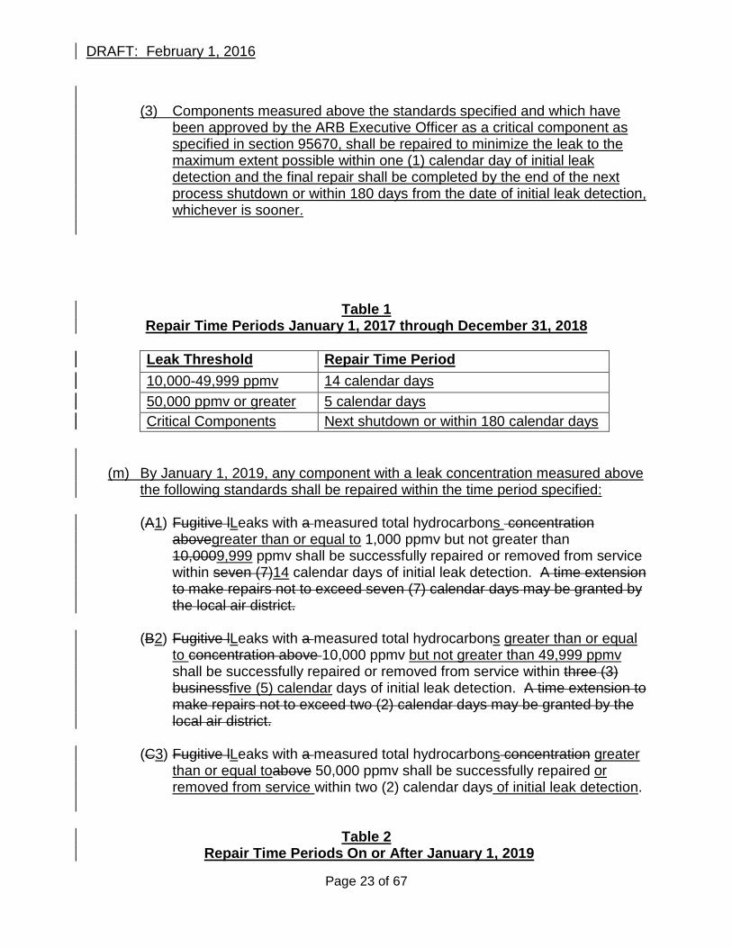
Table 1 Repair Time Periods January 1, 2017 through December 31, 2018
Leak Threshold Repair Time Period 10,000-49,999 ppmv 14 calendar days 50,000 ppmv or greater 5 calendar days Critical Components Next shutdown or within 180 calendar days
(m) By January 1, 2019, any component with a leak concentration measured above the following standards shall be repaired within the time period specified:
(A1) Fugitive lLeaks with a measured total hydrocarbons concentration
abovegreater than or equal to 1,000 ppmv but not greater than 10,0009,999 ppmv shall be successfully repaired or removed from service within seven (7)14 calendar days of initial leak detection. A time extension to make repairs not to exceed seven (7) calendar days may be granted by the local air district.
(B2) Fugitive lLeaks with a measured total hydrocarbons greater than or equal
to concentration above 10,000 ppmv but not greater than 49,999 ppmv shall be successfully repaired or removed from service within three (3) businessfive (5) calendar days of initial leak detection. A time extension to make repairs not to exceed two (2) calendar days may be granted by the local air district.
(C3) Fugitive lLeaks with a measured total hydrocarbons concentration greater
than or equal toabove 50,000 ppmv shall be successfully repaired or removed from service within two (2) calendar days of initial leak detection.
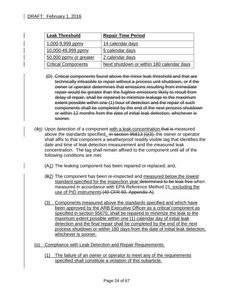
Table 2 Repair Time Periods On or After January 1, 2019
Page 23 of 67
DRAFT: February 1, 2016
Leak Threshold Repair Time Period
1,000-9,999 ppmv 14 calendar days 10,000-49,999 ppmv 5 calendar days 50,000 ppmv or greater 2 calendar days Critical Components Next shutdown or within 180 calendar days
(D) Critical components found above the minor leak threshold and that are
technically infeasible to repair without a process unit shutdown, or if the owner or operator determines that emissions resulting from immediate repair would be greater than the fugitive emissions likely to result from delay of repair, shall be repaired to minimize leakage to the maximum extent possible within one (1) hour of detection and the repair of such components shall be completed by the end of the next process shutdown or within 12 months from the date of initial leak detection, whichever is sooner.
(4n) Upon detection of a component with a leak concentration that is measured
above the standards specified, in section 95813 (i)(3), the owner or operator shall affix to that component a weatherproof readily visible tag that identifies the date and time of leak detection measurement and the measured leak concentration. The tag shall remain affixed to the component until all of the following conditions are met:
(A1) The leaking component has been repaired or replaced; and,
(B2) The component has been re-inspected and measured below the lowest standard specified for the inspection year determined to be leak free when measured in accordance with EPA Reference Method 21, excluding the use of PID instruments (40 CFR 60, Appendix A).
(3) Components measured above the standards specified and which have
been approved by the ARB Executive Officer as a critical component as specified in section 95670, shall be repaired to minimize the leak to the maximum extent possible within one (1) calendar day of initial leak detection and the final repair shall be completed by the end of the next process shutdown or within 180 days from the date of initial leak detection, whichever is sooner.
(o) Compliance with Leak Detection and Repair Requirements:
(1) The failure of an owner or operator to meet any of the requirements
specified shall constitute a violation of this subarticle.
Page 24 of 67
DRAFT: February 1, 2016
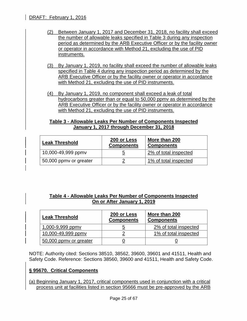
(2) Between January 1, 2017 and December 31, 2018, no facility shall exceed the number of allowable leaks specified in Table 3 during any inspection period as determined by the ARB Executive Officer or by the facility owner or operator in accordance with Method 21, excluding the use of PID instruments.
(3) By January 1, 2019, no facility shall exceed the number of allowable leaks
specified in Table 4 during any inspection period as determined by the ARB Executive Officer or by the facility owner or operator in accordance with Method 21, excluding the use of PID instruments.
(4) By January 1, 2019, no component shall exceed a leak of total
hydrocarbons greater than or equal to 50,000 ppmv as determined by the ARB Executive Officer or by the facility owner or operator in accordance with Method 21, excluding the use of PID instruments.
Table 3 - Allowable Leaks Per Number of Components Inspected
January 1, 2017 through December 31, 2018
Leak Threshold 200 or Less Components
More than 200 Components
10,000-49,999 ppmv 5 2% of total inspected
50,000 ppmv or greater 2 1% of total inspected
Table 4 - Allowable Leaks Per Number of Components Inspected On or After January 1, 2019
Leak Threshold 200 or Less Components
More than 200 Components
1,000-9,999 ppmv 5 2% of total inspected 10,000-49,999 ppmv 2 1% of total inspected 50,000 ppmv or greater 0 0
NOTE: Authority cited: Sections 38510, 38562, 39600, 39601 and 41511, Health and Safety Code. Reference: Sections 38560, 39600 and 41511, Health and Safety Code. § 95670. Critical Components (a) Beginning January 1, 2017, critical components used in conjunction with a critical
process unit at facilities listed in section 95666 must be pre-approved by the ARB
Page 25 of 67
DRAFT: February 1, 2016
Executive Officer if owners or operators wish to claim any critical component exemptions available under this subarticle.
(b) Each critical component shall be identified as shown in Appendix A, Table A3 and
submitted to ARB for approval by no later than June 30, 2017 or within 180 days from the installation of a new critical component.
(c) Owners or operators must provide sufficient documentation showing that a critical
component is required as part of a critical process unit and that shutting down the critical component would result in emissions greater than the emissions measured from the component.
(d) Approval of a critical component may be granted only if owners or operators fully
comply with this section. The ARB Executive Officer retains discretion to deny any application for approval.
NOTE: Authority cited: Sections 38510, 38562, 39600, 39601 and 41511, Health and Safety Code. Reference: Sections 38560, 39600 and 41511, Health and Safety Code § 9521495671. Record Keeping Requirements. (a) OBeginning January 1, 2017, owners or operators of equipment in source categories
listed in section 95211 are required tofacilities listed in section 95666 subject to requirements specified in sections 95668 and 95669 shall maintain, and make available upon request by ARB or the local air districta copy of the following records, records identified below:
Primary and Secondary VesselsFlash Analysis Testing
(1) Maintain, for at five years from the date of each test, a record of flash analysis testing that shall include the following:
(A) A sketch or diagram of each separator and tank system tested that
identifies the liquid sampling location and all pressure vessels, separators tanks, sumps, and ponds within the system; and,
(B) A record of the flash analysis testing results, calculations, and a
description of the separator and tank system as specified in Appendix A Table A1; and,
(C) A field testing form for each flash analysis test conducted as specified in
Appendix C Form 1; and, (D) The laboratory report(s) for each flash analysis test conducted.Maintain a
record of flash analysis testing including a diagram of the primary and
Page 26 of 67
DRAFT: February 1, 2016
secondary vessels with the sampling location, laboratory reports, and accompanying information as described in Appendix C, Table 1.
Reciprocating Natural Gas Compressors (2) For a minimum of five (5) years, maintain a record identifying rod packing or
seal emission measurements and maintenance activity for each compressor at or below 500 rate horsepower as described in Appendix C, Table 2.
(3) For a minimum of five (5) years, maintain a record of rod packing emission
flow rate measurements and maintenance activity for each compressor over 500 rated horsepower as described in Appendix C, Table 2.
Liquids Unloading of Natural Gas Wells
(42) Maintain, for at least two years following the measurement or calculation, a
record of the measured or calculated volume of natural gas vented to perform liquids unloading and equipment installed in the natural gas well(s) designed to automatically perform liquids unloading (e.g., foaming agent, velocity tubing, plunger lift, etc.) as specified in Appendix A Table A2.For a minimum of five (5) years, maintain a record of the volume of natural gas that is vented to remove accumulated liquids for each production well that is vented and not connected to a vapor collection system as described in Appendix C, Table 3 ; and,
(5) For a minimum of five (5) years, maintain a record of equipment installed in
each production well and designed to automatically unload liquids (e.g., plunger-lift system, velocity tubing, soap solution) for each production well that is vented to remove accumulated liquids and is not connected to a vapor collection system as described in Appendix C, Table 3.
Leak Detection and Repair
(63) For a minimum of five (5) years, maintain a record of leak detection and repair
activities that include the following: (A) Date, name, and location of operation inspected. (B) Type of component found leaking. (C) Measured total hydrocarbon concentration (ppmv). (D) Date of repair or date(s) of attempted repair. (E) Measured total hydrocarbon concentration (ppmv) after leak is repaired.
Page 27 of 67
DRAFT: February 1, 2016
(F) Total number of components inspected, total number of leaks identified, and percentage of leaking components.
(G) Current record identifying all components awaiting repair. (H) Type of leak detection instrument(s) used to conduct the inspection including
date and time of instrument calibration(s) as required by the instrument manufacturer.Maintain, for at least two years from each inspection, a record of each leak detection and repair inspection as specified in Appendix A Table A4.
(4) Maintain, for at least two years from each inspection, a component leak
concentration and repair form for each inspection as specified in Appendix A Table A5.
NOTE: Authority cited: Sections 38510, 38562, 39600, 39601, 39607, and 41511, Health and Safety Code. Reference: Sections 38560, 39600 and 41511, Health and Safety Code. § 9521595672. Reporting Requirements. (a) OBeginning January 1, 2018, owners or operators of equipment in source
categoriesfacilities listed in section 95211 95666 subject to requirements specified in sections 95668 and 95669 shall report the following information to ARB are required to information identified below within the timeframes specified:
Flash Analysis TestingPrimary and Secondary Vessels (1) Within 90 days of performing flash analysis testing, report the test results,
calculations, and a description of the separator and tank system as specified in Appendix A Table A1.or within 90 days after subsequent testing, report the results of flash analysis testing, including a diagram of the primary and secondary vessels with the sampling location, the laboratory reports, and accompanying information as described in Appendix B, Table 1 to the local air district enforcing the requirements of this regulation and to the ARB using the contact information provided in section 95215(b).
Liquids Unloading of Natural Gas Production Wells
(2) Annually, report the measured or calculated volume of natural gas vented to
perform liquids unloading and equipment installed in the natural gas well(s) designed to automatically perform liquids unloading as specified in Appendix A Table A3.that is vented to remove accumulated liquids for each production well that is vented and not connected to a vapor collection system as described in Appendix C, Table 3 to the ARB using the contact information provided in section 95215(b); and,
Page 28 of 67
DRAFT: February 1, 2016
(3) Annually, report equipment installed in each production well and designed to
automatically unload liquids (e.g., plunger-lift system, velocity tubing, soap solution) for each production well that is vented to remove accumulated liquids and is not connected to a vapor collection system as described in Appendix C, Table 3 to the ARB using the contact information provided in section 95215(b).
Leak Detection and Repair
(43) AnnuallyOnce per calendar year, report a summary ofthe results of each leak detection inspection conducted during the calendar year as specified in Appendix A Table A4.
(4) Once per calendar year, report the initial and final component leak
concentration(s) for each inspection conducted during the calendar year as specified in Appendix A Table A5.and repair activities as described in Appendix C, Table 4 to the ARB using the contact information provided in section 95215(b).
(b) Reports may be e-mailed electronically to ARB with the subject line “O&G GHG
Regulation Reporting” to oil&[email protected] or mailed to: California Air Resources Board Attention: O&G GHG Regulation Reporting Industrial Strategies Division 1001 I Street Sacramento, California 95814
NOTE: Authority cited: Sections 38510, 38562, 39600, 39601, 39607, and 41511, Health and Safety Code. Reference: Sections 38560, 39600 and 41511, Health and Safety Code. § 9521695673. Implementation. (a) Implementation by ARB and by the Local Air Districts
(1) The requirements of this subarticlearticle are provisions of state law that apply to the owners and operators of equipment in the categories listed in section 95211 of this Article and are enforceable by both ARB and the local air districtss in whichwhere the equipment covered by this subarticle is located. Local air districts may incorporate the terms of this subarticle into local air district rules. An owner or operator of equipment subject to this subarticlearticle must pay any fees assessed by a locanl air district for the purposes of recovering the air district’s cost of implementing and enforcing the requirements of this subarticlearticle. Any penalties secured by a localn air district as the
Page 29 of 67
DRAFT: February 1, 2016
result of an enforcement action that it undertakes to enforce the provisions of this subarticle may be retained by the local air district.
(2) The ARB Executive Officer, at his or her discretion, may enter into an
agreement or agreements with any local air district to further define implementation and enforcement processes, including arrangements further specifying approaches for implementation and enforcement of this subarticle, and for information sharing between ARB and local air districtss, relating to this subarticlearticle.
(3) Implementation and enforcement of the requirements of this subarticlearticle by
an local air district may in no instance result in a standard, requirement, or prohibition less stringent than provided for by this subarticlearticle, as determined by the Executive Officer. The terms of any local air district permit or rule relating to this subarticlearticle do not alter the terms of this subarticlearticle, which remain as separate requirements for all sources subject to this subarticlearticle.
(4) Implementation and enforcement of the requirements of this subarticlearticle by
an local air district, including inclusion or exclusion of any of its terms within any local air district permit, or within a local air district rule ,rule, or registration of a facility with a localn air district or ARB, does not in any way waive or limit ARB’s authority to implement and enforce upon the requirements of this subarticleArticle. A facility’s permitting or registration status also in no way limits the ability of a local air districts to enforce the requirements of this subarticlearticle.
(b) Requirements for Covered Entities
(1) Local Air District Permitting Requirements
(A) Owners or operators of facilities with or equipment regulated by this subarticlearticle, and who are required by federal, state, or local law to hold local air district permits that cover that cover those facilities or equipment shall ensure that their local air district permits for those facilities or equipment contain terms ensuring compliance with this article. This requirement applies to facilities or equipment upon issuance of any new local air district permit covering these facilities or equipment, or upon the scheduled renewal of an existing permit covering these facilities or equipment.
for those facilities shall ensure on the timeline set out in this subsection that
their local air district permits for those facilities ensure that all equipment at each facility is in compliance with this article. Any combination of local air district permits that, individually or collectively, are shown to ARB’s
Page 30 of 67
DRAFT: February 1, 2016
satisfaction to ensure the compliance of all of an owner or operator’s equipment subject to this article satisfies this requirement.
(B) For existing facilities with equipment subject to this article, owners or
operators of those facilities must comply with this subsection for each such facility by the next air district permit renewal date for the facility,or by [Month, Day Year], whichever is sooner.
(C) For new facilities installed after [Month, Day, Year] with equipment subject
to this article, owners or operators of this equipment must ensure that all local air district permits for those facilities include terms that ensure compliance with this article.
(DB) If, after the effective date of this articlesubarticle, any local air district
amends or adopts permitting rules that result in additional facilities with equipment or facilities regulated by this articlesubarticle becoming subject to local air district permitting requirements, then this subsection applies to those newly-covered facilities. Oowners or operators of those facilitiesthat equipment or facility must ensure that any applicable local air district permits for those facilitiesthat equipment or facility ensures compliance with this articlesubarticle within two years of the effective date of the local air district rule amendment that resulted in the facility being covered for local air district permitting purposesupon issuance of any relevant permit.
(2) Reporting and Registration Requirements for Facilities Not Subject to an Air
District Permitting Program
(A) Owners or operators of facilities with or equipment that is covered regulated by this articlesubarticle which are not included in a local air district permitting program shall register the equipment at each facility by reporting the following information to ARB as specified in Appendix A Table A6 by no later than January 1, 2019, [Month, Day, Year]. The information shall be reported to ARB unless the relevant local air district has established a registration or permitting program that collects at least the following information, and has entered into an MOU with ARB specifying how information is to be shared with ARB.
1. The owner or operator’s name and contact information for the
equipment covered by this article. 2. A description of the crude oil or natural gas facility where the
equipment is locatedThe address or location of each facility with equipment regulated by this subarticle.
3. A description of all equipment covered by this articlesubarticle
located at the each facility which shall includeing the following:
Page 31 of 67
DRAFT: February 1, 2016
(a) The number of crude oil or natural gas wells at the facility. (b) A list of identifying all pressure vessels, tanks, and separators,
sumps, and ponds at the facility, including the size of each tank and separator in units of barrels.
(c) The annual crude oil, natural gas, and produced water throughput of the facility.
(d) A list of identifying all reciprocating and centrifugal natural gas compressors at the facility, including the manufacturer’s horsepower rating for each compressor.
(e) A count of all pneumatic devices and pumps at the facility.
4. The permit numbers of all local air district permits issued for the facility or equipment, and an identification of permit terms that ensure complianceensure compliance with the terms of this subarticle, or an explanation of why such terms are not included.
5. An attestation that all information provided in the registration is
provided by a party authorized by the owner or operator to do so, and that the information is true and correct.
(B) Updates to these reports, recording any changes in this information, must be filed with ARB, or, as relevant, with the local air district no later than January 1 of the calendar year after the year in which any information required by this subarticle has changed. [Month, Day] each year if the owner or operator has installed or removed any equipment covered by this article at its facility.
(3) Owners or operators of equipment subject to this articlesubarticle must comply
with all the requirements of sections 9521195666, 985621267, 95213668, 95214669, 9521595670, 95671, 95672, and 95217 95673 of this articlesubarticle, regardless of whether or not they have complied with the permitting and registration requirements of this subsection.
secured local air district permits or registered the equipment with ARB or the local air district where the facility is located.
NOTE: Authority cited: Sections 38510, 38562, 39600, 39601, 39603, 39607, and 41511, Health and Safety Code. Reference: Sections 38560, 39600, 40701, 40702, 41511, 42300, 42301, and 42311, Health and Safety Code. § 9521795674. Enforcement.
Page 32 of 67
DRAFT: February 1, 2016
(a) Failure to comply with the requirements of this articlesubarticle at each individual
piece of equipment subject to this articlesubarticle constitutes a single, separate, violation of this articlesubarticle.
(b) Each day, or portion thereof, that an owner or operator is not in full compliance with
the requirements of this articlesubarticle is a single, separate, violation of this articlesubarticle.
(c) Each metric ton of methane emitted in violation of this subarticle constitutes a single,
separate, violation of this subarticle. (cd) Failure to submit any report required by this articlesubarticle shall constitute a
single, separate violation of this articlesubarticle for each day or portion thereof that the report has not been received after the date the report is due.
(de) Failure to retain and failure to produce any record that this articlesubarticle requires
to be retained or produced shall each constitute a single, separate violation of this articlesubarticle for each day or portion thereof that the record has not been retained or produced.
(f) Falsifying any information or record required to be submitted or retained by this
subarticle, or submitting or producing inaccurate information, shall be a violation of this subarticle.
NOTE: Authority cited: Sections 38510, 38562, 38580, 39600, 39601, 39607, and 41511, Health and Safety Code. Reference: Sections 38560, 39600 and 41511, Health and Safety Code. § 9521895675. No Preemption of More Stringent Air District or Federal Requirements This regulation does not preempt any more stringent requirements imposed by any Air District. Compliance with this articlesubarticle does not excuse noncompliance with any Federal regulation. The ARB Executive Officer retains authority to determine whether an Air District requirement is more stringent than any requirement of this Articlesubarticle. NOTE: Authority cited: Sections 38510, 38562, 39600, 39601 and 41511, Health and Safety Code. Reference: Sections 38560, 39600 and 41511, Health and Safety Code. § 9521995676. Severability Each part of this articlesubarticle is deemed severable, and in the event that any part of this articlesubarticle is held to be invalid, the remainder of the articlesubarticle shall continue in full force and effect.
Page 33 of 67
DRAFT: February 1, 2016
NOTE: Authority cited: Sections 38510, 38562, 39600, 39601 and 41511, Health and Safety Code. Reference: Sections 38560, 39600 and 41511, Health and Safety Code.
Page 34 of 67
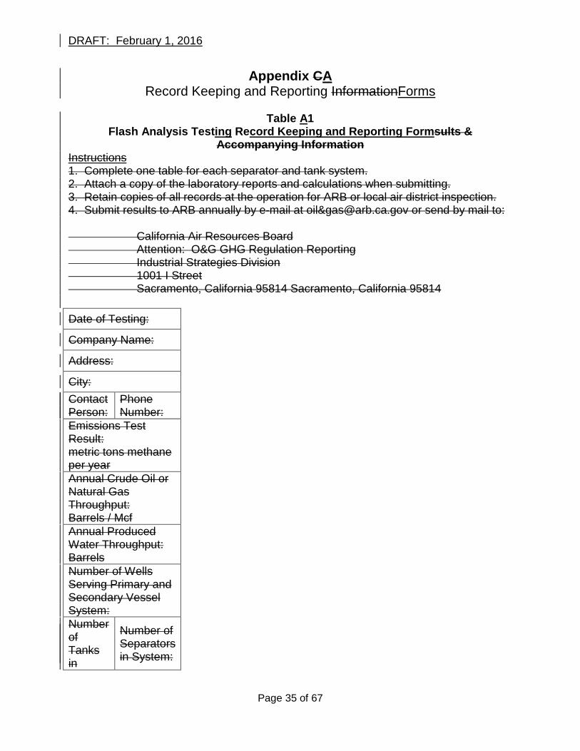
DRAFT: February 1, 2016
Appendix CA Record Keeping and Reporting InformationForms
Table A1
Flash Analysis Testing Record Keeping and Reporting Formsults & Accompanying Information
Instructions 1. Complete one table for each separator and tank system. 2. Attach a copy of the laboratory reports and calculations when submitting. 3. Retain copies of all records at the operation for ARB or local air district inspection. 4. Submit results to ARB annually by e-mail at oil&[email protected] or send by mail to: California Air Resources Board Attention: O&G GHG Regulation Reporting Industrial Strategies Division 1001 I Street Sacramento, California 95814 Sacramento, California 95814 Date of Testing:
Company Name:
Address:
City: Contact Person:
Phone Number:
Emissions Test Result: metric tons methane per year Annual Crude Oil or Natural Gas Throughput: Barrels / Mcf Annual Produced Water Throughput: Barrels Number of Wells Serving Primary and Secondary Vessel System: Number of Tanks in
Number of Separators in System:
Page 35 of 67
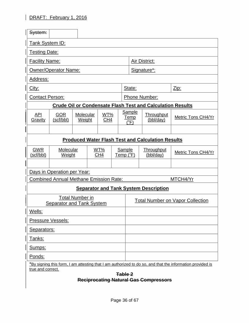
DRAFT: February 1, 2016
System:
Tank System ID:
Testing Date:
Facility Name: Air District:
Owner/Operator Name: Signature*:
Address:
City: State: Zip:
Contact Person: Phone Number:
Crude Oil or Condensate Flash Test and Calculation Results
API Gravity
GOR (scf/bbl)
Molecular Weight
WT% CH4
Sample Temp (oF)
Throughput (bbl/day) Metric Tons CH4/Yr
Produced Water Flash Test and Calculation Results
GWR (scf/bbl)
Molecular Weight
WT% CH4
Sample Temp (oF)
Throughput (bbl/day) Metric Tons CH4/Yr
Days in Operation per Year: Combined Annual Methane Emission Rate: MTCH4/Yr
Separator and Tank System Description
Total Number in Separator and Tank System Total Number on Vapor Collection
Wells:
Pressure Vessels:
Separators:
Tanks:
Sumps:
Ponds: *By signing this form, I am attesting that I am authorized to do so, and that the information provided is true and correct.
Table 2 Reciprocating Natural Gas Compressors
Page 36 of 67
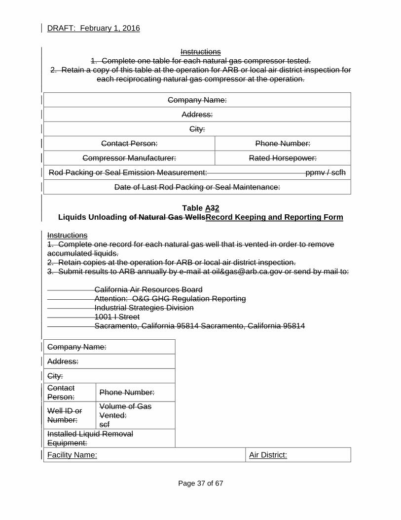
DRAFT: February 1, 2016
Instructions 1. Complete one table for each natural gas compressor tested.
2. Retain a copy of this table at the operation for ARB or local air district inspection for each reciprocating natural gas compressor at the operation.
Company Name:
Address:
City:
Contact Person: Phone Number:
Compressor Manufacturer: Rated Horsepower:
Rod Packing or Seal Emission Measurement: ppmv / scfh
Date of Last Rod Packing or Seal Maintenance:
Table A32 Liquids Unloading of Natural Gas WellsRecord Keeping and Reporting Form
Instructions 1. Complete one record for each natural gas well that is vented in order to remove accumulated liquids. 2. Retain copies at the operation for ARB or local air district inspection. 3. Submit results to ARB annually by e-mail at oil&[email protected] or send by mail to: California Air Resources Board Attention: O&G GHG Regulation Reporting Industrial Strategies Division 1001 I Street Sacramento, California 95814 Sacramento, California 95814 Company Name:
Address:
City: Contact Person: Phone Number:
Well ID or Number:
Volume of Gas Vented: scf
Installed Liquid Removal Equipment: Facility Name: Air District:
Page 37 of 67
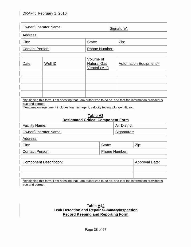
DRAFT: February 1, 2016
Owner/Operator Name: Signature*:
Address:
City: State: Zip:
Contact Person: Phone Number:
Date Well ID Volume of Natural Gas Vented (Mcf)
Automation Equipment**
*By signing this form, I am attesting that I am authorized to do so, and that the information provided is true and correct. **Automation equipment includes foaming agent, velocity tubing, plunger lift, etc.
Table A3
Designated Critical Component Form Facility Name: Air District:
Owner/Operator Name: Signature*:
Address:
City: State: Zip:
Contact Person: Phone Number: Component Description: Approval Date:
*By signing this form, I am attesting that I am authorized to do so, and that the information provided is true and correct.
Table A44 Leak Detection and Repair SummaryInspection
Record Keeping and Reporting Form
Page 38 of 67
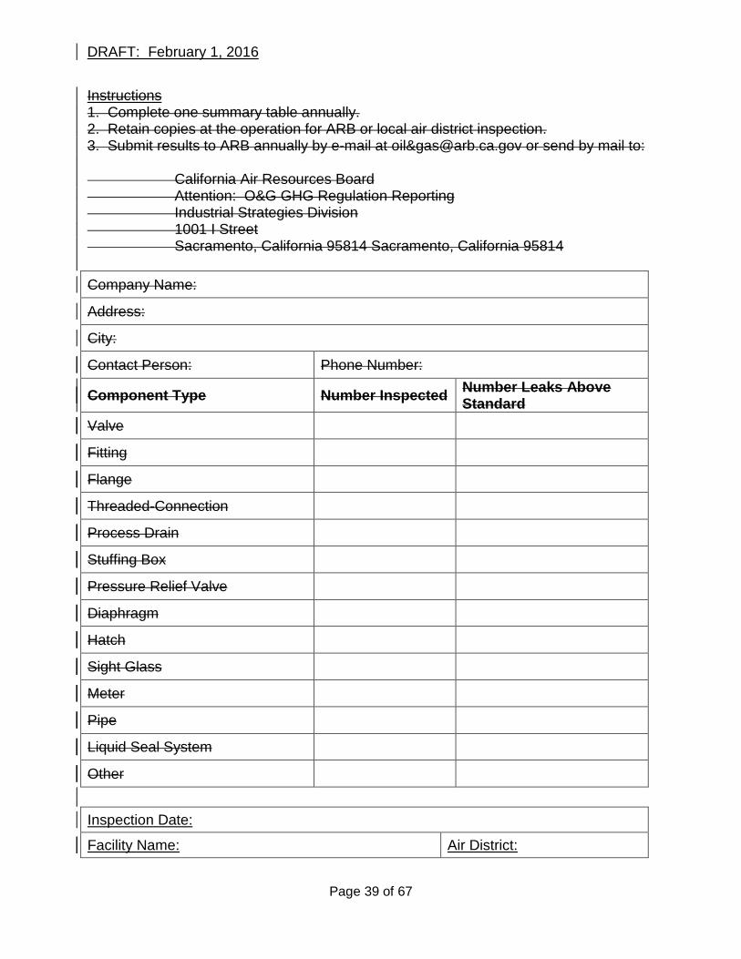
DRAFT: February 1, 2016
Instructions 1. Complete one summary table annually. 2. Retain copies at the operation for ARB or local air district inspection. 3. Submit results to ARB annually by e-mail at oil&[email protected] or send by mail to: California Air Resources Board Attention: O&G GHG Regulation Reporting Industrial Strategies Division 1001 I Street Sacramento, California 95814 Sacramento, California 95814 Company Name:
Address:
City:
Contact Person: Phone Number:
Component Type Number Inspected Number Leaks Above Standard
Valve
Fitting
Flange
Threaded-Connection
Process Drain
Stuffing Box
Pressure Relief Valve
Diaphragm
Hatch
Sight Glass
Meter
Pipe
Liquid Seal System
Other
Inspection Date:
Facility Name: Air District:
Page 39 of 67
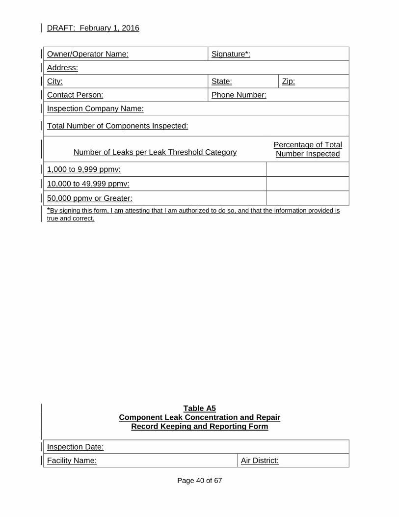
DRAFT: February 1, 2016
Owner/Operator Name: Signature*:
Address:
City: State: Zip:
Contact Person: Phone Number:
Inspection Company Name:
Total Number of Components Inspected:
Number of Leaks per Leak Threshold Category Percentage of Total Number Inspected
1,000 to 9,999 ppmv:
10,000 to 49,999 ppmv:
50,000 ppmv or Greater:
*By signing this form, I am attesting that I am authorized to do so, and that the information provided is true and correct.
Table A5 Component Leak Concentration and Repair
Record Keeping and Reporting Form Inspection Date:
Facility Name: Air District:
Page 40 of 67
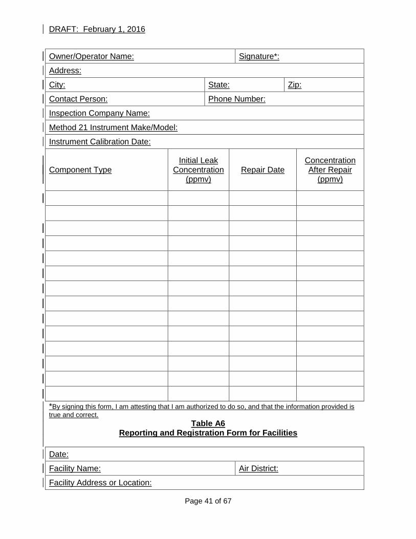
DRAFT: February 1, 2016
Owner/Operator Name: Signature*:
Address:
City: State: Zip:
Contact Person: Phone Number:
Inspection Company Name:
Method 21 Instrument Make/Model:
Instrument Calibration Date:
Component Type Initial Leak
Concentration (ppmv)
Repair Date Concentration After Repair
(ppmv)
*By signing this form, I am attesting that I am authorized to do so, and that the information provided is true and correct.
Table A6 Reporting and Registration Form for Facilities
Date:
Facility Name: Air District:
Facility Address or Location:
Page 41 of 67
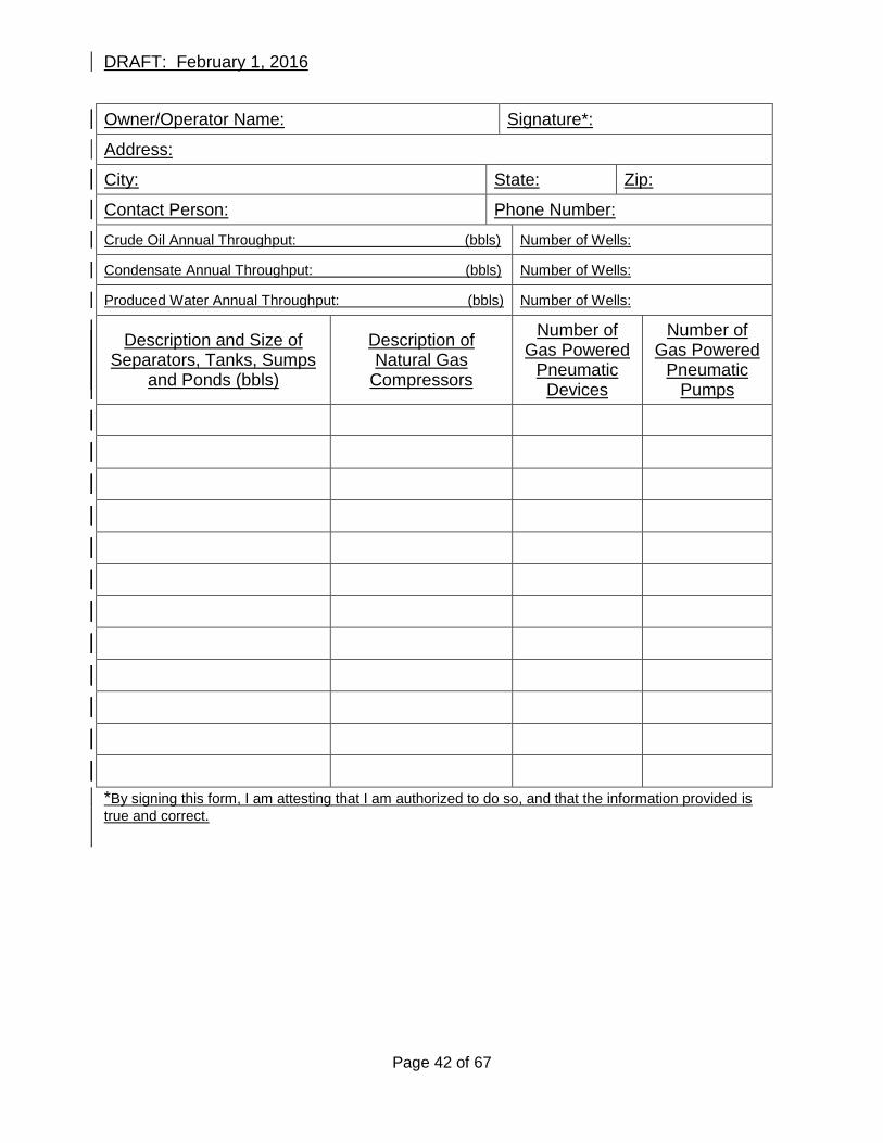
DRAFT: February 1, 2016
Owner/Operator Name: Signature*:
Address:
City: State: Zip:
Contact Person: Phone Number:
Crude Oil Annual Throughput: (bbls) Number of Wells:
Condensate Annual Throughput: (bbls) Number of Wells:
Produced Water Annual Throughput: (bbls) Number of Wells:
Description and Size of Separators, Tanks, Sumps
and Ponds (bbls)
Description of Natural Gas
Compressors
Number of Gas Powered
Pneumatic Devices
Number of Gas Powered
Pneumatic Pumps
*By signing this form, I am attesting that I am authorized to do so, and that the information provided is true and correct.
Page 42 of 67
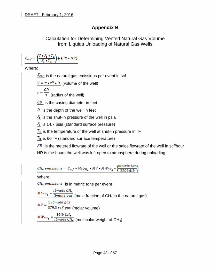
DRAFT: February 1, 2016
Appendix B
Calculation for Determining Vented Natural Gas Volume from Liquids Unloading of Natural Gas Wells
Where:
is the natural gas emissions per event in scf
(volume of the well)
(radius of the well)
is the casing diameter in feet
is the depth of the well in feet
is the shut-in pressure of the well in psia
is 14.7 psia (standard surface pressure)
is the temperature of the well at shut-in pressure in °F
is 60 °F (standard surface temperature)
is the metered flowrate of the well or the sales flowrate of the well in scf/hour HR is the hours the well was left open to atmosphere during unloading
Where:
is in metric tons per event
(mole fraction of CH4 in the natural gas)
(molar volume)
(molecular weight of CH4)
Page 43 of 67
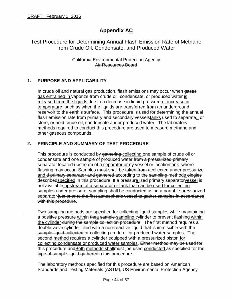
DRAFT: February 1, 2016
Appendix AC
Test Procedure for Determining Annual Flash Emission Rate of Methane from Crude Oil, Condensate, and Produced Water
California Environmental Protection Agency
Air Resources Board 1. PURPOSE AND APPLICABILITY
In crude oil and natural gas production, flash emissions may occur when gases gas entrained in vaporize from crude oil, condensate, or produced water is released from the liquids due to a decrease in liquid pressure or increase in temperature, such as when the liquids are transferred from an underground reservoir to the earth's surface. This procedure is used for determining the annual flash emission rate from primary and secondary vesselstanks used to separate, or store, or hold crude oil, condensate andor produced water. The laboratory methods required to conduct this procedure are used to measure methane and other gaseous compounds.
2. PRINCIPLE AND SUMMARY OF TEST PROCEDURE
This procedure is conducted by gathering collecting one sample of crude oil or condensate and one sample of produced water from a pressurized primary separator located upstream of a separator or ny vessel or locationtank where flashing may occur. Samples must shall be taken from acollected under pressurize and d primary separator and gathered according to the sampling methods ologies describedspecified in this procedure. If a pressure ized primary separatorvessel is not available upstream of a separator or tank that can be used for collecting samples under pressure, sampling shall be conducted using a portable pressurized separator just prior to the first atmospheric vessel to gather samples in accordance with this procedure. Two sampling methods are specified for collecting liquid samples while maintaining a positive pressure within thea sample sampling cylinder to prevent flashing within the cylinder during the sample collection procedure. The first method requires a double valve cylinder filled with a non-reactive liquid that is immiscible with the sample liquid collectedfor collecting crude oil or produced water samples. The second method requires a cylinder equipped with a pressurized piston for collecting condensate or produced water samples. Either method may be used for this procedure andBoth methods shallmust be used conducted as specified for the type of sample liquid gatheredin this procedure. The laboratory methods specified for this procedure are based on American Standards and Testing Materials (ASTM), US Environmental Protection Agency
Page 44 of 67
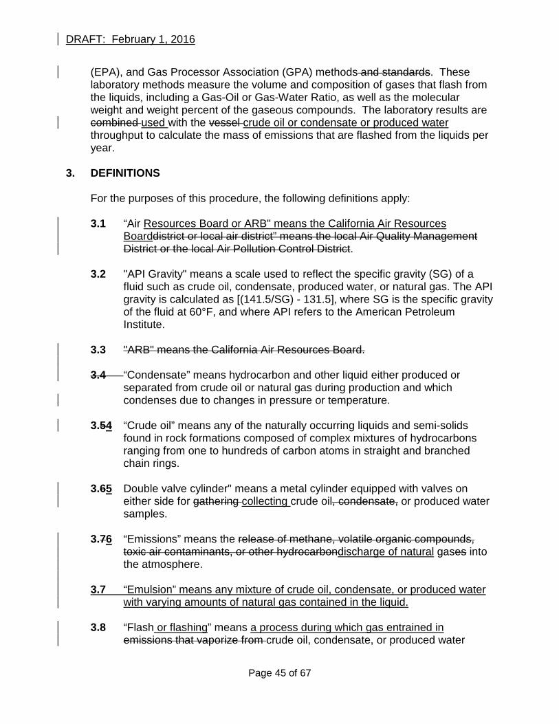
DRAFT: February 1, 2016
(EPA), and Gas Processor Association (GPA) methods and standards. These laboratory methods measure the volume and composition of gases that flash from the liquids, including a Gas-Oil or Gas-Water Ratio, as well as the molecular weight and weight percent of the gaseous compounds. The laboratory results are combined used with the vessel crude oil or condensate or produced water throughput to calculate the mass of emissions that are flashed from the liquids per year.
3. DEFINITIONS For the purposes of this procedure, the following definitions apply:
3.1 “Air Resources Board or ARB" means the California Air Resources Boarddistrict or local air district” means the local Air Quality Management District or the local Air Pollution Control District.
3.2 "API Gravity" means a scale used to reflect the specific gravity (SG) of a
fluid such as crude oil, condensate, produced water, or natural gas. The API gravity is calculated as [(141.5/SG) - 131.5], where SG is the specific gravity of the fluid at 60°F, and where API refers to the American Petroleum Institute.
3.3 "ARB" means the California Air Resources Board. 3.4 “Condensate” means hydrocarbon and other liquid either produced or
separated from crude oil or natural gas during production and which condenses due to changes in pressure or temperature.
3.54 “Crude oil” means any of the naturally occurring liquids and semi-solids
found in rock formations composed of complex mixtures of hydrocarbons ranging from one to hundreds of carbon atoms in straight and branched chain rings.
3.65 Double valve cylinder" means a metal cylinder equipped with valves on
either side for gathering collecting crude oil, condensate, or produced water samples.
3.76 “Emissions” means the release of methane, volatile organic compounds,
toxic air contaminants, or other hydrocarbondischarge of natural gases into the atmosphere.
3.7 “Emulsion” means any mixture of crude oil, condensate, or produced water
with varying amounts of natural gas contained in the liquid. 3.8 “Flash or flashing” means a process during which gas entrained in
emissions that vaporize from crude oil, condensate, or produced water
Page 45 of 67
DRAFT: February 1, 2016
under pressure is released when the liquids are subject to a decrease in pressure or increase in temperature, such as when liquids are transferred from an underground reservoir to a tank on the earth’s surface.
3.9 “Gas-Oil Ratio (GOR)” means a measurement used to describe the volume
of gas that is flashed from a barrel of crude oil or condensate.
3.10 “Gas-Water Ratio (GWR)” means a measurement used to describe the volume of gas that is flashed from a barrel of produced water.
3.11 “Natural gas” means a naturally occurring mixture or process derivative of
hydrocarbon and non-hydrocarbon gases, of which its constituents include methane, carbon dioxide, and heavier hydrocarbons. Natural gas may be field quality (which varies widely) or pipeline quality.
3.1112 “Operating pressure” means the working steady-state pressure of the the vessel from which a sample is collectedpressurized primary separator from which a sample is gathered.. If no pressure gauge is available or the sampling train pressure gauge reading is greater than +/- 5 psig of the vessel pressure, the sampling train pressure gauge reading shall be used to record the steady state pressure on Form 1.
3.1213 “Operating temperature” means the working steady-state temperature of
the the vessel from which a sample is collectedpressurized primary separator from which a sample is gathered.. If no temperature gauge is available or the sampling train temperature gauge reading is greater than +/- 4oF of the vessel temperature, the sampling train temperature gauge reading shall be used to record the steady state temperature on Form 1.
3.1314 “Percent water cut” means the volume percentage of produced water to
crude oil or condensateby volume, of the total emulsion throughput as measured using ASTM D-4007. The percent water cut is expressed as a percentage.
3.1415 “Piston cylinder” means a metal cylinder containing an internal pressurized
piston for gathering collecting crude oil, condensate, or produced water samples.
3.165 "Portable pressurized separator" means a sealed metal vessel that can be
moved from one location to another by attachment to a motor vehicle without having to be dismantled and is used for used for separating and measuringand sampling crude oil, or condensate, andor produced water , and may allow for metering natural gas volume. The vessel is used to
Page 46 of 67
DRAFT: February 1, 2016
separate the liquids while they continuously flow through the vessel at the steady-state conditions temperature and pressure of the separator and tank system required for sampling.upstream of any vessel or location where flashing may occur.
3.1617 “Pressurized primary separatorvessel” means any vessel rated, as
indicated by an ASME pressure rating stamp, and operated to contain normal working pressures of at least 15 psig without vapor loss to the atmosphere and may be used for the separation of crude oil, condensate, produced water, or natural gas..the first vessel that receives crude oil, condensate, or produced water from one or more crude oil or natural gas wells and is pressurized to at least five (5) pounds per square inch gauge pressure and allows liquids to continuously flow through the unit at steady state conditions. The pressurized primary separator must be located upstream of any vessel or location where flashing may occur.
3.18 “Produced water” means water recovered from an underground reservoir as
a result of crude oil, condensate, or natural gas production and which may be recycled, disposed, or re-injected into an underground reservoir.
3.19 “Separator” means any tank designed to contain a normal working pressure
of less than 15 psig and is used for the separation of crude oil, condensate, produced water, or natural gas.
3.20 "Separator and tank system" means any combination of pressure vessels or
tanks used to separate, store, or hold emulsion, crude oil, condensate, or produced water with varying quantities of natural gas.
3.2121 “Tank” means any container constructed primarily of non-earthen
materials used for the purpose of to circulate or storeing or holding emulsion, crude oil, condensate, or produced water.
3.2222 “Throughput” means the average volume of crude oil, condensate, or
produced water expressed processed by a vessel in units of barrels per day. 3.23 “Vessel” means any tank or separator used to separate, store, or circulate
crude oil, condensate, or produced water.
4. BIASES AND INTERFERENCES
4.1 The sampling method used to gather collect a liquid sample will have an impact on the final results reported. Liquid samples shall be gathered collected in accordance with the sampling procedures specified in this procedure.
Page 47 of 67
DRAFT: February 1, 2016
4.2 The vessel used to gather a liquid samplelocation from where a sample is collected will have an impact on the final results reported. Liquid samples shall be gathered collected from a pressurized primarye vessel or portable pressurized separator as specified in this procedure.
4.3 Collecting liquid samples from a pressure vessel or portable pressurized
separator that periodically drains liquids will have an impact on the final results reported. Samples shall not be collected from a pressure vessel or portable pressurized separator while it periodically drains liquids.
4.34 Collecting liquid samples from using an empty double valve cylinder without
displacing an inert immiscible liquid from the cylinder will allow gases to flash from the cylinder and bias will have an impact on the final results reported. Liquids sSamples gathered collected using a double valve cylinder shall be gathered collected as specified in this procedure.
4.5,4 Displacing liquids from a double valve cylinder that are reactive and not
immiscible with the sample liquid to be collected from a double valve cylinder canwill result in gas composition or volume errors and will affect the final results reported results. Displacement liquids shall be pre-tested by a laboratory to verify that the liquid is non-reactive and is immiscible with the sample liquid to be collected.
4.56 Non-calibrated equipment including pressure or temperature gauges will
bias have an impact the final results reported. All pressure and temperature measurements shall be conducted with calibrated gauges as specified in this procedure.
4.67 Conducting laboratory procedures other than those specified in this
procedure will bias have an impact on the final results reported. All laboratory methods and quality control and quality assurance procedures shall be conducted as specified in this procedure.
5. SAMPLING EQUIPMENT SPECIFICATIONS
5.1 A pressure gauge capable of measuring liquid pressures of less than 50
pound per square inch gauge pressure within +/-10% accuracy. 5.2 A pressure gauge capable of measuring liquid pressures greater than 50
pounds per square inch gauge pressure within +/- 5% accuracy. 5.3 A temperature gauge capable of reading liquid temperature within +/- 2oF
and within a range of 32oF to 200oF250oF.
Page 48 of 67
DRAFT: February 1, 2016
5.4 A graduated cylinder capable of measuring liquid in one at least five (15) milliliter increments with at least the same capacity as the double valve cylinder used for liquid sampling.
5.5 A portable pressurized separator that is sealed from the atmosphere and is
used for capable of collecting crude oil, condensate, and produced water samples at the steady state temperature and pressure of the separator and tank system being sampled.measuring crude oil or condensate and produced water throughput within +/- 1 barrel per hour accuracy.
6. SAMPLING TEST EQUIPMENT
6.1 A double valve cylinder or a piston cylinder. 6.2 A graduated cylinder for use with double valve cylinder. 6.3 A waste container suitable for capturing and disposing sample liquid. 6.4 High-pressure rated metal components and control valves that can
withstand the temperature and pressure of the pressure ized primary vessel or portable pressurized separator being sampled.
6.5 Pressure gauges with minimum specifications listed in section 5. 6.6 A temperature gauge with minimum specifications listed in section 5. 6.7 A If required, a portable pressurized separator capable of measuring crude
oil or condensate and produced water throughput while allowing liquids to continuously flow through the vessel with minimum specifications listed in section 5.
7. DATA REQUIREMENTS
7.1 The data requirements required to conduct this procedure shall be provided by the facility owner or operator prior to conducting the sampling methods specified in this procedure. Field sampling shall not be performed until all data requirements are provided as listed in section 7.2 and as specified on Form 1.
7.2 For each pressure vessel or portable pressurized primary or portable
separator sampled, the sampling technician shall be provided with the following information whichfollowing data shall be recorded on the samplinge cylinder identification tag and on Form 1 prior to conducting a sample collection method at the time of liquid sampling: (a) The separator identification number or description.; and,
Page 49 of 67
DRAFT: February 1, 2016
(b) The separator temperature and pressure if available.; and (c) Crude oil or condensate throughput; or,. (d) Produced water throughput.; and, (e) Percent water cut.; and, (f) Crude oil storage tank temperature if heated; and, (g(f) Gas volume flow rate of three phase separator if available.; and, (gh) Number of wells in the separator and tank system.; and, (hi) Days of operation per year.
8. DOUBLE VALVE CYLINDER SAMPLING METHOD
8.1 The double valve cylinder sampling method is used for collecting crude oil
or produced water samples and is not applicable for collecting samples of condensate. Liquid samples of condensate shall be collected using the piston cylinder sampling method specified in section 9.
8.2 Fill the double valve cylinder with non-reactive liquid that is immiscible with
the liquid to be collected to prevent flashing within the cylinder and to prevent the displacement liquid from mixing or attaining homogeneity with the sample liquid.
8.23 Locate the a pressure vessel ized immediately upstream of the separator or
tank required for testing primary separator for sampling and verify it is pressurized to at least 10 15 psig and located upstream of any vessel or location where flashing may occur. Install a portable pressurized separator if no pressurized pressure primary separatorvessel is available immediately upstream of the separator or tank that can be used to collect crude oil and produced water samples.
8.34 Record the information sample collection data requirements specified in
section 7 on the cylinder identification tag and on Form 1. 8.45 Locate the sampling port(s) for gathering collecting liquid samples. 8.56 Connect the sampling train as illustrated in Figure 1 to the sampling port on
the pressure vessel or portable pressurized separator while minimizing tubing between the purge valve and cylinder as shown. Bushings or reducers may be required.
8.67 Purge the sampling train: Place the outlet of valve B into the waste
container. With valves B, C and D closed, slowly open valve A completely, and then slowly open valve B to purge the sample train until a steady stream of liquid without gas pockets is observed, and then close valve B.
8.78 Prepare for sampling: Orient the double-valve cylinder in the vertical
position so that displacement liquid can readily be discharged from the
Page 50 of 67
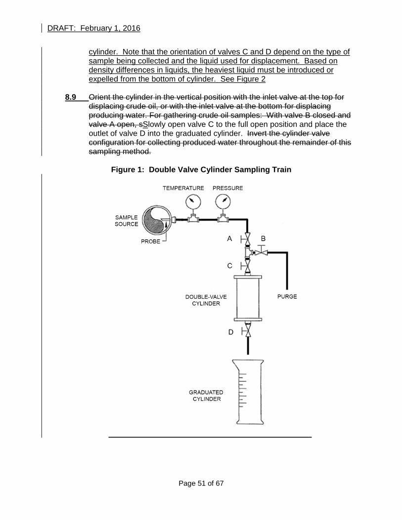
DRAFT: February 1, 2016
cylinder. Note that the orientation of valves C and D depend on the type of sample being collected and the liquid used for displacement. Based on density differences in liquids, the heaviest liquid must be introduced or expelled from the bottom of cylinder. See Figure 2
8.9 Orient the cylinder in the vertical position with the inlet valve at the top for
displacing crude oil, or with the inlet valve at the bottom for displacing producing water. For gathering crude oil samples: With valve B closed and valve A open, sSlowly open valve C to the full open position and place the outlet of valve D into the graduated cylinder. Invert the cylinder valve configuration for collecting produced water throughout the remainder of this sampling method.
Figure 1: Double Valve Cylinder Sampling Train
Page 51 of 67
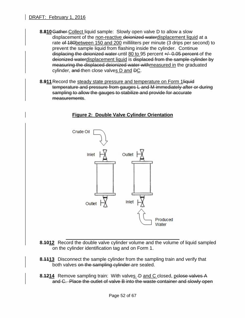
DRAFT: February 1, 2016
8.810 Gather Collect liquid sample: Slowly open valve D to allow a slow displacement of the non-reactive deionized waterdisplacement liquid at a rate of 180between 150 and 200 milliliters per minute (3 drips per second) to prevent the sample liquid from flashing inside the cylinder. Continue displacing the deionized water until 80 to 95 percent +/- 0.05 percent of the deionized waterdisplacement liquid is displaced from the sample cylinder by measuring the displaced deionized water withmeasured in the graduated cylinder, and then close valves D and DC.
8.911 Record the steady state pressure and temperature on Form 1liquid
temperature and pressure from gauges L and M immediately after or during sampling to allow the gauges to stabilize and provide for accurate measurements.
Figure 2: Double Valve Cylinder Orientation
8.1012 Record the double valve cylinder volume and the volume of liquid sampled
on the cylinder identification tag and on Form 1. 8.1113 Disconnect the sample cylinder from the sampling train and verify that
both valves on the sampling cylinder are sealed.
8.1214 Remove sampling train: With valves D and C closed, pclose valves A and C. Place the outlet of valve B into the waste container and slowly open
Page 52 of 67
DRAFT: February 1, 2016
valve B to purge liquid from the sampling train. Close valve B and durge any remaining liquid in the sampling train through valve B. Then close valves A and B. Disconnect the sampling train from the sample port on thepressure vessel or portable pressurized separator.
8.1315 Verify that all of the data requirements are recorded on the cylinder
identification tag and on Form 1.
8.1416 Transport the cylinder to the laboratory for conducting the laboratory methods specified in section 12.
9. PISTON CYLINDER SAMPLING METHOD
9.1 Locate a pressure vessel immediately upstream of the separator or tank required for testing the pressurized primary separator for sampling and verify it is pressurized to at least 10 15 psig and located upstream of any vessel or location where flashing may occur. Install a portable pressurized separator if no pressure vessel ized primary separator is available immediately upstream of the separator or tank that can be used to collect condensate and produced water samples.
9.2 Record the information sample collection data requirements specified in
section 7 on the cylinder identification tag and on Form 1. 9.3 Locate the sampling port(s) for gathering collecting liquid samples. 9.4 Connect the sampling train as illustrated in Figure 2 3 to the pressure vessel
or pressurized portablesampling port on the separator while minimizing tubing between the purge valve and cylinder as shown. Bushings or reducers may be required.
9.5 Purge the sampling train: Place the outlet of valve B into the waste container.
With valves B, C and D closed, slowly open valve A completely, and then slowly open valve B to purge the sample train until a steady stream of liquid without gas pockets is observed, and then close valve B.
Figure 23: Piston Cylinder Sampling Train
Page 53 of 67
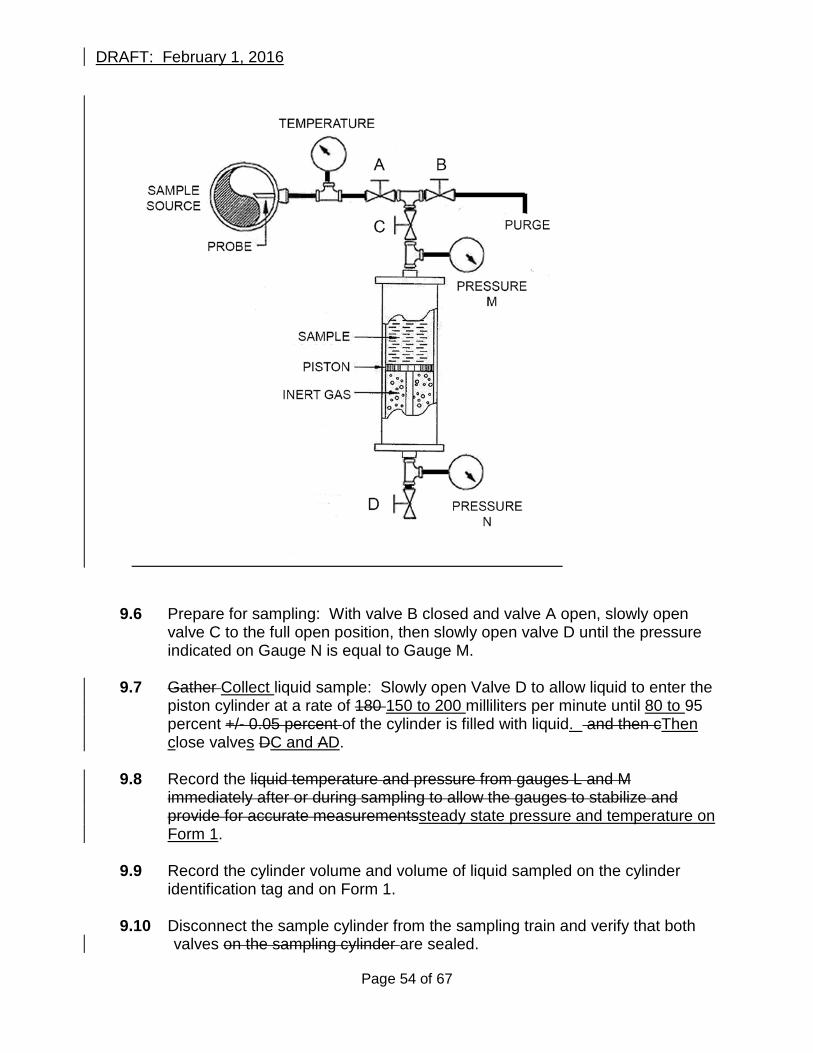
DRAFT: February 1, 2016
9.6 Prepare for sampling: With valve B closed and valve A open, slowly open valve C to the full open position, then slowly open valve D until the pressure indicated on Gauge N is equal to Gauge M.
9.7 Gather Collect liquid sample: Slowly open Valve D to allow liquid to enter the
piston cylinder at a rate of 180 150 to 200 milliliters per minute until 80 to 95 percent +/- 0.05 percent of the cylinder is filled with liquid. and then cThen close valves DC and AD.
9.8 Record the liquid temperature and pressure from gauges L and M
immediately after or during sampling to allow the gauges to stabilize and provide for accurate measurementssteady state pressure and temperature on Form 1.
9.9 Record the cylinder volume and volume of liquid sampled on the cylinder
identification tag and on Form 1. 9.10 Disconnect the sample cylinder from the sampling train and verify that both
valves on the sampling cylinder are sealed.
Page 54 of 67
DRAFT: February 1, 2016
9.11 Remove sampling train: With valve D closed, close valves A and C. Place
the outlet of valve B into the waste container and slowly open valve B to purge all liquid from the sampling train. Close valve B Then close valves A and B. Disconnect the sampling train from the pressure vessel or portable pressurized separator.
. 9.12 Verify that all of the data requirements are recorded on the cylinder
identification tag and on Form 1. 9.13 Transport the cylinder to the laboratory for conducting the laboratory methods
as specified in section 12. 11. REPORTING RESULTS 11.1 The results of this procedure are used to report annual methane flash emission rates to the Air Resources Board as well as the local air district if the local district is enforcing these testing requirements. The following information shall be provided when test results are submitted: (a) A copy of Form 1; and, (b) A copy of all laboratory reports; and, (c) A copy of calculations with annual methane flash emission rate; and, (d) A sketch or diagram of all vessels in the separator and tank system including the location from where samples where taken. 11.2 Reports may be e-mailed electronically to ARB with the subject line “O&G GHG Regulation Reporting” to oil&[email protected] or mailed to: California Air Resources Board Attention: O&G GHG Regulation Reporting Industrial Strategies Division 1001 I Street Sacramento, California 95814
1210. LABORATORY REQUIREMENTS AND METHODS 10.1 Quality Control, Quality Assurance, and Field Records (a) Quality control requirements shall be performed in accordance with the
laboratory methods specified in this test procedure. (b) Each day of sampling, at least one field duplicate sample shall be collected
per matrix type (crude oil, condensate, produced water). The field duplicate samples are collected to demonstrate acceptable method precision by the laboratory at the time of analysis. Through this process the laboratory can
Page 55 of 67
DRAFT: February 1, 2016
evaluate the consistency of sample collection and analytical measurements as well as matrix variation. The laboratory should establish control limits based on relative percent difference to evaluate the validity of the measured results.
(c) Laboratory procedures shall be in place for establishing acceptance criteria
for field activities described in sections 7, 8 and 9 of this procedure. All deviations from the acceptance criteria shall be documented. Deviations from the acceptance criteria may or may not affect data quality.
(d) Laboratory procedures shall be in place to ensure that field staff have been
trained on the sampling methods specified in this procedure and retrained on sampling methods if this procedure changes.
(e) Field records shall provide direct evidence and support necessary for
technical interpretations, judgments, and discussions concerning project activities and shall, at a minimum, include a completed copy of Form 1 as provided in this procedure for each sample collected.
1210.12 Flash LiberationLaboratory Flash Analysis Test Equipment Requirements
(a) All laboratory equipment used to conduct measurements shall be calibrated in accordance with the manufacturer specifications and in accordance with the laboratory methods specified in this procedure.
(b) Any chromatograph system that allows for the collection, storage, interpretation, adjustment, or quantification of chromatograph detector output signals representing relative component concentrations may be used to conduct this procedure. All test methods and quality control requirements shall be conducted in accordance with each laboratory method specified.
(c) The minimum reporting limit of the instruments used for reporting gaseous
compounds must be at least 100 parts per million (ppm) for both hydrocarbon and fixed gases.
(d) The laboratory apparatus used for heating sample cylinders must be capable of heating and maintaining Liquid samples must be heated to the steady state same temperature measured at the time of sampling and allowed to cool at a rate no greater than five (5) degrees Fahrenheit per minute and then held at constant storage temperature or ambient temperature as noted reported on Form 1.
(be) The laboratory apparatus used for collecting gas flashed from liquids must be temperature and pressure controlled whilecapable of precisely measuring gas liquid and gas volume, temperature, and pressure.
Page 56 of 67
DRAFT: February 1, 2016
.
(cf) The laboratory apparatus vessel used for collecting gas flashed from liquids must be capable of collecting or storing the liberated flash gas for gas for chromatography analysis without sample degradation and without compromising the integrity of the sample. .
(d) The liberated flash gas volume may decrease during sample cooling. The laboratory apparatus or procedure used for conducting flash liberation gas volume measurements shall account for gas volume shrinkage.
(ge) Additional sample preparation guidance can be found in GPA 2174, GPA
2261 and GPA 2177.
102.32 Laboratory Flash Liberation Analysis Test RequirementsProcedure (a) Heat the sample cylinder to the sample collection temperature recorded as
reported on Form 1 and allow the temperature to stabilize for at leasta minimum of 30 minutes.
(b) After the cylinder temperature has stabilized, open the cylinder and collect all
gas flashed from the liquid for a minimum of 30 minutes while monitoring the gas pressure and temperature. begin the flash liberation volume measurement and adjust the temperature to the storage or ambient temperature recorded on Form 1.
(c) Allow the sample to cool at a rate no greater than five (5) degrees Fahrenheit
per minute while collecting the flash liberation gas and monitoring gas pressure and accounting for volume shrinkage.
(dc) After all gas has flashed from the cylinder for a minimum of 30 minutes,
eAllow the sample to cool to the storage temperature or ambient temperature recorded on Form 1 for a minimum of 30 minutes.
(e) Continue nsure that the gasmeasuring the flash liberation gas volume until
the gas pressure has stabilizeds at ambient pressure and with no changes in gas pressure observed are evident for at least 30 minutes.. In the event that the gas pressure changes or remains above ambient pressure after 30 minutes, continue to allow the cylinder to flash until the gas pressure stabilizes at ambient pressure. The collected gas sample can now be used for gas chromatography analysis.
(d) At least 0.20 standard cubic feet of sample gas per barrel of liquid is required
to conduct the laboratory procedures specified in this procedure. If insufficient gas volume is collected during the flash analysis procedure, additional laboratory analyses cannot be completed while maintaining the accuracy requirements specified in this procedure.
Page 57 of 67
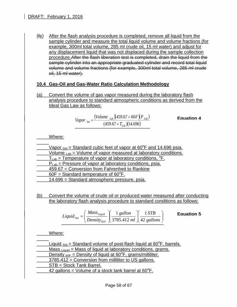
DRAFT: February 1, 2016
(fe) After the flash analysis procedure is completed, remove all liquid from the
sample cylinder and measure the total liquid volume and volume fractions (for example, 300ml total volume, 285 ml crude oil, 15 ml water) and adjust for any displacement liquid that was not displaced during the sample collection procedure.After the flash liberation test is completed, drain the liquid from the sample cylinder into an appropriate graduated cylinder and record total liquid volume and volume fractions (for example, 300ml total volume, 285 ml crude oil, 15 ml water).
10.4 Gas-Oil and Gas-Water Ratio Calculation Methodology (a) Convert the volume of gas vapor measured during the laboratory flash
analysis procedure to standard atmospheric conditions as derived from the Ideal Gas Law as follows:
( )( )( )
( )696.14)67.459(6067.459
Lab
LabLabStd T
PFVolumeVapor
++
=
Where: Vapor Std = Standard cubic feet of vapor at 60oF and 14.696 psia. Volume Lab = Volume of vapor measured at laboratory conditions. TLab = Temperature of vapor at laboratory conditions, oF. PLab = Pressure of vapor at laboratory conditions, psia. 459.67 = Conversion from Fahrenheit to Rankine 60F = Standard temperature of 60oF. 14.696 = Standard atmospheric pressure, psia. (b) Convert the volume of crude oil or produced water measured after conducting
the laboratory flash analysis procedure to standard conditions as follows:
=
gallonsSTB
mlgallon
DensityMass
LiquidF
LiquidStd 42
1412.3785
1
60
Where: Liquid Std = Standard volume of post-flash liquid at 60oF, barrels. Mass Liquid = Mass of liquid at laboratory conditions, grams. Density 60F = Density of liquid at 60oF, grams/milliliter. 3785.412 = Conversion from milliliter to US gallons. STB = Stock Tank Barrel. 42 gallons = Volume of a stock tank barrel at 60oF.
Equation 5
Equation 4
Page 58 of 67
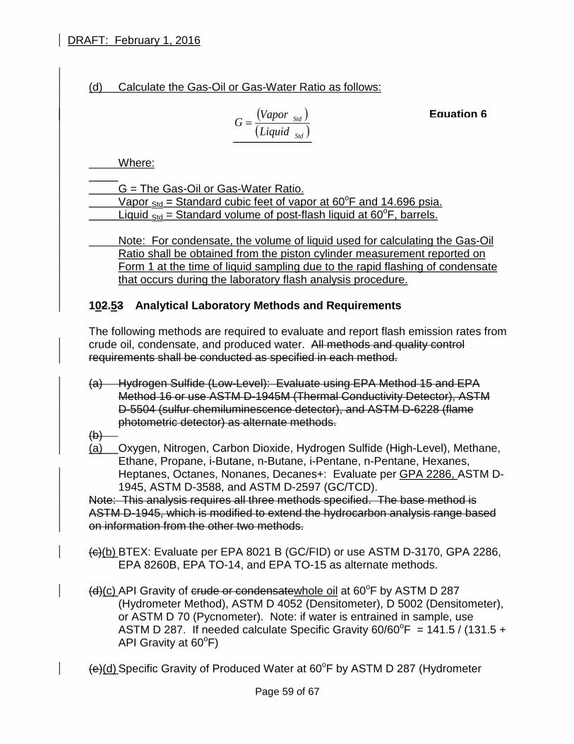
DRAFT: February 1, 2016
(d) Calculate the Gas-Oil or Gas-Water Ratio as follows:
( )( )Std
Std
LiquidVapor
G =
Where: G = The Gas-Oil or Gas-Water Ratio. Vapor Std = Standard cubic feet of vapor at 60oF and 14.696 psia. Liquid Std = Standard volume of post-flash liquid at 60oF, barrels. Note: For condensate, the volume of liquid used for calculating the Gas-Oil
Ratio shall be obtained from the piston cylinder measurement reported on Form 1 at the time of liquid sampling due to the rapid flashing of condensate that occurs during the laboratory flash analysis procedure.
102.53 Analytical Laboratory Methods and Requirements
The following methods are required to evaluate and report flash emission rates from crude oil, condensate, and produced water. All methods and quality control requirements shall be conducted as specified in each method.
(a) Hydrogen Sulfide (Low-Level): Evaluate using EPA Method 15 and EPA
Method 16 or use ASTM D-1945M (Thermal Conductivity Detector), ASTM D-5504 (sulfur chemiluminescence detector), and ASTM D-6228 (flame photometric detector) as alternate methods.
(b) (a) Oxygen, Nitrogen, Carbon Dioxide, Hydrogen Sulfide (High-Level), Methane,
Ethane, Propane, i-Butane, n-Butane, i-Pentane, n-Pentane, Hexanes, Heptanes, Octanes, Nonanes, Decanes+: Evaluate per GPA 2286, ASTM D-1945, ASTM D-3588, and ASTM D-2597 (GC/TCD).
Note: This analysis requires all three methods specified. The base method is ASTM D-1945, which is modified to extend the hydrocarbon analysis range based on information from the other two methods. (c)(b) BTEX: Evaluate per EPA 8021 B (GC/FID) or use ASTM D-3170, GPA 2286,
EPA 8260B, EPA TO-14, and EPA TO-15 as alternate methods. (d)(c) API Gravity of crude or condensatewhole oil at 60oF by ASTM D 287
(Hydrometer Method), ASTM D 4052 (Densitometer), D 5002 (Densitometer), or ASTM D 70 (Pycnometer). Note: if water is entrained in sample, use ASTM D 287. If needed calculate Specific Gravity 60/60oF = 141.5 / (131.5 + API Gravity at 60oF)
(e)(d) Specific Gravity of Produced Water at 60oF by ASTM D 287 (Hydrometer
Equation 6
Page 59 of 67
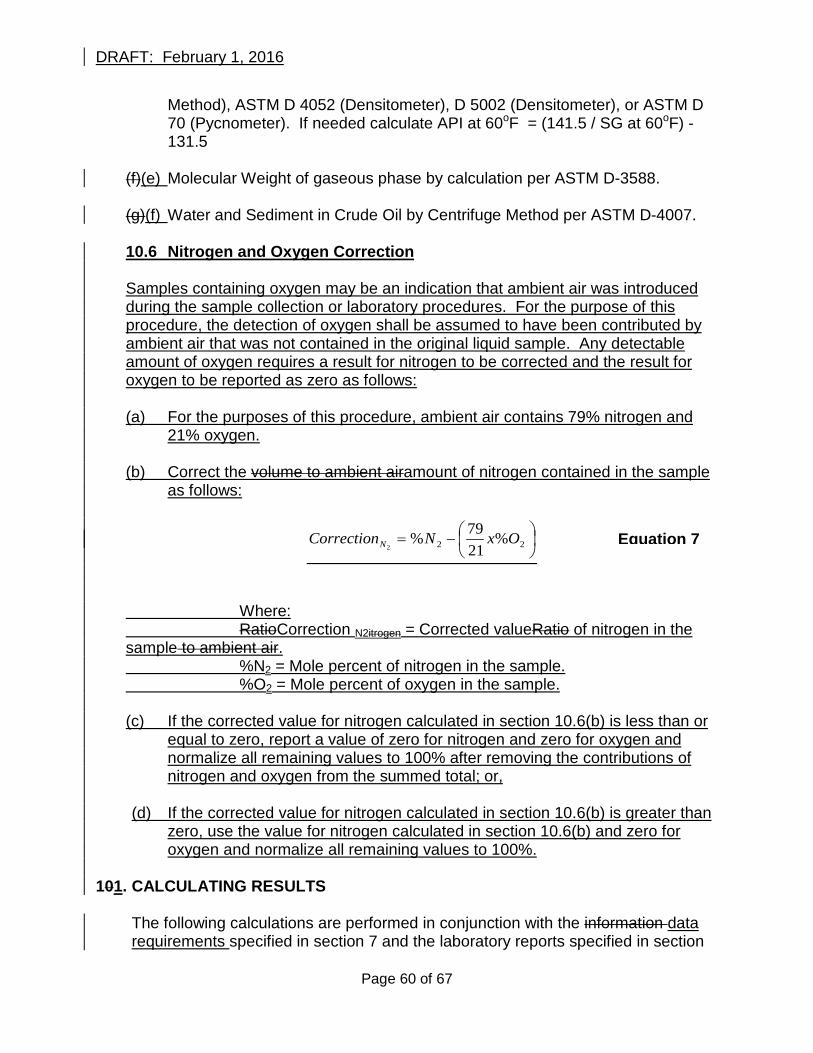
DRAFT: February 1, 2016
Method), ASTM D 4052 (Densitometer), D 5002 (Densitometer), or ASTM D 70 (Pycnometer). If needed calculate API at 60oF = (141.5 / SG at 60oF) - 131.5
(f)(e) Molecular Weight of gaseous phase by calculation per ASTM D-3588. (g)(f) Water and Sediment in Crude Oil by Centrifuge Method per ASTM D-4007. 10.6 Nitrogen and Oxygen Correction
Samples containing oxygen may be an indication that ambient air was introduced during the sample collection or laboratory procedures. For the purpose of this procedure, the detection of oxygen shall be assumed to have been contributed by ambient air that was not contained in the original liquid sample. Any detectable amount of oxygen requires a result for nitrogen to be corrected and the result for oxygen to be reported as zero as follows: (a) For the purposes of this procedure, ambient air contains 79% nitrogen and
21% oxygen. (b) Correct the volume to ambient airamount of nitrogen contained in the sample
as follows:
−= 22 %
2179%
2OxNCorrectionN
Where: RatioCorrection N2itrogen = Corrected valueRatio of nitrogen in the sample to ambient air. %N2 = Mole percent of nitrogen in the sample. %O2 = Mole percent of oxygen in the sample. (c) If the corrected value for nitrogen calculated in section 10.6(b) is less than or
equal to zero, report a value of zero for nitrogen and zero for oxygen and normalize all remaining values to 100% after removing the contributions of nitrogen and oxygen from the summed total; or,
(d) If the corrected value for nitrogen calculated in section 10.6(b) is greater than
zero, use the value for nitrogen calculated in section 10.6(b) and zero for oxygen and normalize all remaining values to 100%.
101. CALCULATING RESULTS
The following calculations are performed in conjunction with the information data requirements specified in section 7 and the laboratory reports specified in section
Equation 7
Page 60 of 67
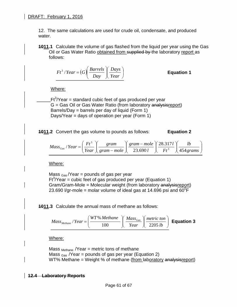
DRAFT: February 1, 2016
12. The same calculations are used for crude oil, condensate, and produced water.
1011.1 Calculate the volume of gas flashed from the liquid per year using the Gas
Oil or Gas Water Ratio obtained from supplied by the laboratory report as follows:
( )
=
YearDays
DayBarrelsGYearFt /3 Equation 1
Where: Ft3/Year = standard cubic feet of gas produced per year G = Gas Oil or Gas Water Ratio (from laboratory analysisreport) Barrels/Day = barrels per day of liquid (Form 1) Days/Year = days of operation per year (Form 1) 1011.2 Convert the gas volume to pounds as follows: Equation 2
−
−
=
gramslb
Ftl
lmolegram
molegramgram
YearFtYearMassGas 454
317.28690.23
/ 3
3
Where: Mass Gas /Year = pounds of gas per year Ft3/Year = cubic feet of gas produced per year (Equation 1) Gram/Gram-Mole = Molecular weight (from laboratory analysisreport) 23.690 l/gr-mole = molar volume of ideal gas at 14.696 psi and 600F
1011.3 Calculate the annual mass of methane as follows:
=
lbtonmetric
YearMassMethaneWT
YearMass GasMethane 2205100
%/ Equation 3
Where: Mass Methane /Year = metric tons of methane Mass Gas /Year = pounds of gas per year (Equation 2) WT% Methane = Weight % of methane (from laboratory analysisreport)
12.4 Laboratory Reports
Page 61 of 67
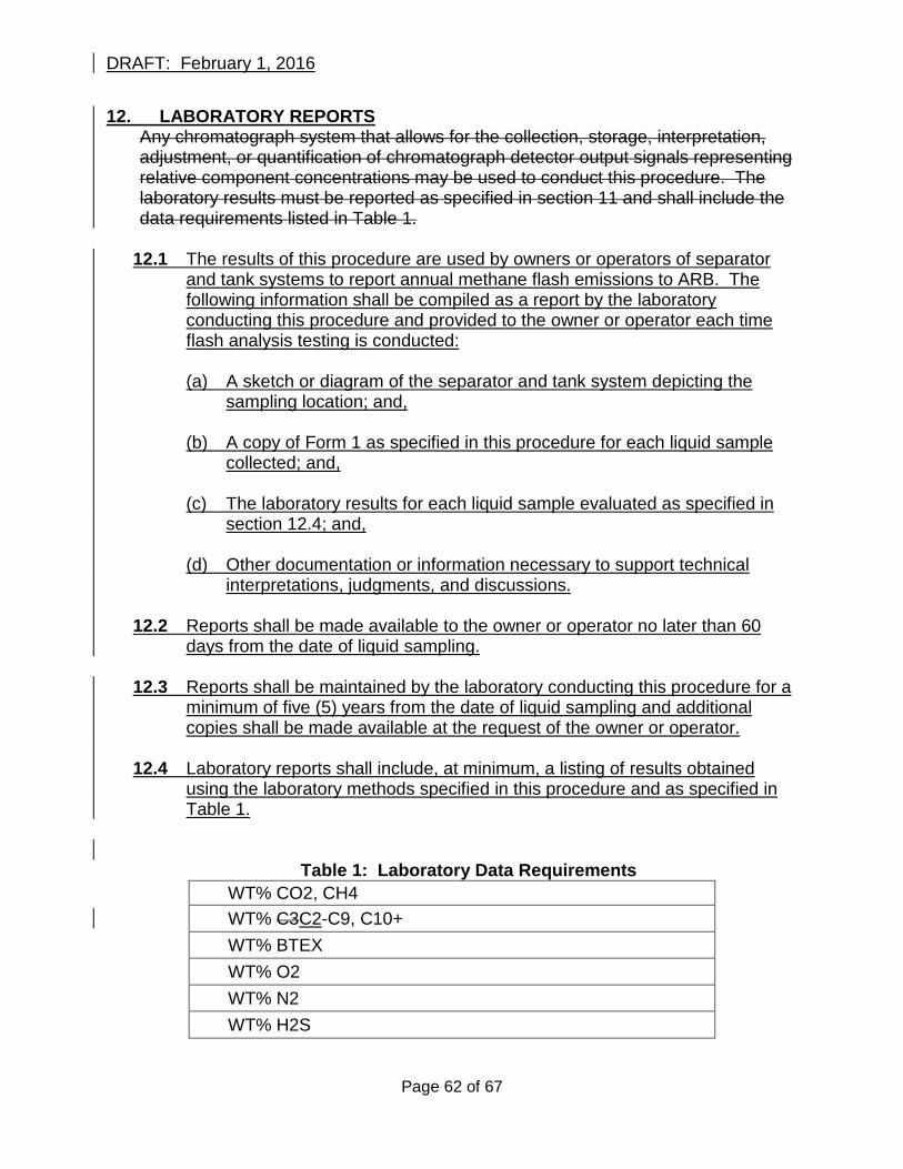
DRAFT: February 1, 2016
12. LABORATORY REPORTS Any chromatograph system that allows for the collection, storage, interpretation, adjustment, or quantification of chromatograph detector output signals representing relative component concentrations may be used to conduct this procedure. The laboratory results must be reported as specified in section 11 and shall include the data requirements listed in Table 1.
12.1 The results of this procedure are used by owners or operators of separator and tank systems to report annual methane flash emissions to ARB. The following information shall be compiled as a report by the laboratory conducting this procedure and provided to the owner or operator each time flash analysis testing is conducted:
(a) A sketch or diagram of the separator and tank system depicting the
sampling location; and, (b) A copy of Form 1 as specified in this procedure for each liquid sample
collected; and, (c) The laboratory results for each liquid sample evaluated as specified in
section 12.4; and, (d) Other documentation or information necessary to support technical
interpretations, judgments, and discussions.
12.2 Reports shall be made available to the owner or operator no later than 60 days from the date of liquid sampling.
12.3 Reports shall be maintained by the laboratory conducting this procedure for a
minimum of five (5) years from the date of liquid sampling and additional copies shall be made available at the request of the owner or operator.
12.4 Laboratory reports shall include, at minimum, a listing of results obtained
using the laboratory methods specified in this procedure and as specified in Table 1.
Table 1: Laboratory Data Requirements WT% CO2, CH4 WT% C3C2-C9, C10+ WT% BTEX WT% O2 WT% N2 WT% H2S
Page 62 of 67
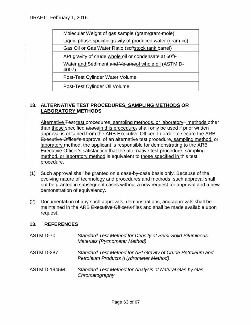
DRAFT: February 1, 2016
Molecular Weight of gas sample (gram/gram-mole) Liquid phase specific gravity of produced water (gram-cc) Gas Oil or Gas Water Ratio (scf/stock tank barrel)
API gravity of crude whole oil or condensate at 60oF Water and Sediment and Volumeof whole oil (ASTM D-4007) Post-Test Cylinder Water Volume
Post-Test Cylinder Oil Volume 13. ALTERNATIVE TEST PROCEDURES, SAMPLING METHODS OR
LABORATORY METHODS
Alternative Test test procedures, sampling methods, or laboratory, methods other than those specified abovein this procedure, shall only be used if prior written approval is obtained from the ARB Executive Officer. In order to secure the ARB Executive Officer's approval of an alternative test procedure, sampling method, or laboratory method, the applicant is responsible for demonstrating to the ARB Executive Officer's satisfaction that the alternative test procedure, sampling method, or laboratory method is equivalent to those specified in this test procedure.
(1) Such approval shall be granted on a case-by-case basis only. Because of the
evolving nature of technology and procedures and methods, such approval shall not be granted in subsequent cases without a new request for approval and a new demonstration of equivalency.
(2) Documentation of any such approvals, demonstrations, and approvals shall be
maintained in the ARB Executive Officer's files and shall be made available upon request.
13. REFERENCES
ASTM D-70 Standard Test Method for Density of Semi-Solid Bituminous
Materials (Pycnometer Method)
ASTM D-287 Standard Test Method for API Gravity of Crude Petroleum and Petroleum Products (Hydrometer Method)
ASTM D-1945M Standard Test Method for Analysis of Natural Gas by Gas
Chromatography
Page 63 of 67
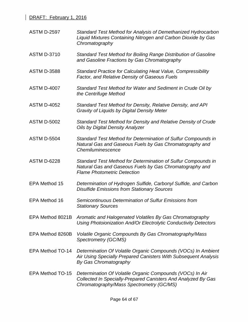
DRAFT: February 1, 2016
ASTM D-2597 Standard Test Method for Analysis of Demethanized Hydrocarbon Liquid Mixtures Containing Nitrogen and Carbon Dioxide by Gas Chromatography
ASTM D-3710 Standard Test Method for Boiling Range Distribution of Gasoline
and Gasoline Fractions by Gas Chromatography ASTM D-3588 Standard Practice for Calculating Heat Value, Compressibility
Factor, and Relative Density of Gaseous Fuels ASTM D-4007 Standard Test Method for Water and Sediment in Crude Oil by
the Centrifuge Method ASTM D-4052 Standard Test Method for Density, Relative Density, and API
Gravity of Liquids by Digital Density Meter ASTM D-5002 Standard Test Method for Density and Relative Density of Crude
Oils by Digital Density Analyzer ASTM D-5504 Standard Test Method for Determination of Sulfur Compounds in
Natural Gas and Gaseous Fuels by Gas Chromatography and Chemiluminescence
ASTM D-6228 Standard Test Method for Determination of Sulfur Compounds in
Natural Gas and Gaseous Fuels by Gas Chromatography and Flame Photometric Detection
EPA Method 15 Determination of Hydrogen Sulfide, Carbonyl Sulfide, and Carbon
Disulfide Emissions from Stationary Sources EPA Method 16 Semicontinuous Determination of Sulfur Emissions from
Stationary Sources
EPA Method 8021B Aromatic and Halogenated Volatiles By Gas Chromatography Using Photoionization And/Or Electrolytic Conductivity Detectors
EPA Method 8260B Volatile Organic Compounds By Gas Chromatography/Mass
Spectrometry (GC/MS) EPA Method TO-14 Determination Of Volatile Organic Compounds (VOCs) In Ambient
Air Using Specially Prepared Canisters With Subsequent Analysis By Gas Chromatography
EPA Method TO-15 Determination Of Volatile Organic Compounds (VOCs) In Air
Collected In Specially-Prepared Canisters And Analyzed By Gas Chromatography/Mass Spectrometry (GC/MS)
Page 64 of 67
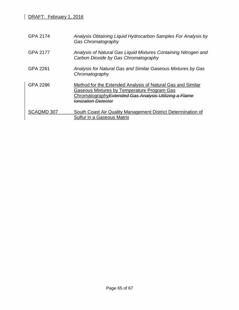
DRAFT: February 1, 2016
GPA 2174 Analysis Obtaining Liquid Hydrocarbon Samples For Analysis by
Gas Chromatography GPA 2177 Analysis of Natural Gas Liquid Mixtures Containing Nitrogen and
Carbon Dioxide by Gas Chromatography GPA 2261 Analysis for Natural Gas and Similar Gaseous Mixtures by Gas
Chromatography GPA 2286 Method for the Extended Analysis of Natural Gas and Similar
Gaseous Mixtures by Temperature Program Gas ChromatographyExtended Gas Analysis Utilizing a Flame Ionization Detector
SCAQMD 307 South Coast Air Quality Management District Determination of
Sulfur in a Gaseous Matrix
Page 65 of 67

DRAFT: February 1, 2016
FORM 1 Flash Analysis Testing Sampling Field Data Form
Attach a sketch or diagram of all vessels in the separator and tank system
including the location from where the sample was taken.
Date of Testing:
Production Company Name:
Address:
City:
Contact: Phone:
Sampling Company Name:
Address:
City:
Contact: Phone: Enter one unique identification name or number for the type of vessel sampled.
Primary Portable Pressurized Separator ID:
Portable Separator ressure Vessel ID: Separator Steady State Pressure: psig Separator Steady State Temperature: oF Crude Oil or Condensate Throughput: Barrels/Day
Produced Water Throughput: Barrels/Day Gas Volume Flow Rate (if metered): Mcf/Day Days of Operation of Separator and Tank System per Year:
Percent Water Cut: % Number of wells in system:
Crude Oil Storage Tank Temperature (if heated): oF Sample Type (circle one): crude oil condensate produced water
Sample Cylinder ID Number:
Cylinder Type: Displacement Liquid:
Page 66 of 67
DRAFT: February 1, 2016
Cylinder Volume: ml Volume of Liquid Collected: ml
Page 67 of 67