Embed Size (px)
Citation preview

OHCP HOUSING REHABILITATION HANDBOOK
PART II
RESIDENTIAL REHABILITATION STANDARDS (RRS)
AND COMMENTARY
Sixth Edition July, 1998
EFFECTIVE DATE: July 31, 1998

ACKNOWLEDGMENTS OHCP would like to thank OCCD and the RRS Revision Committee for contributing their time, insight and technical expertise. The committee members are:
Dale Hartle, OCCD Programs Committee Greg Andrews, HAP Tri-County CAC Anthony Bodo, City of Steubenville Marshall Bleckman, Bleckman & Associates Peggy Beekman, Beekman & Associates Laura Brown, Muskingum County Dave Fisher, CDC of Ohio Dave LaValle, LaValle & Associates Michael Penna, City of Ashtabula Larry Rogers, Fayette County George Taylor, Maumee Valley Planning Organization Ed Tomasko, City of Cambridge Gary Wamer, Poggemeyer Design Group
OHCP would also like to thank the other individuals who reviewed and commented on the drafts.
OHCP Housing Unit Staff:
Les Warner, Supervisor
Dana Leas Rollin Seward Carol Guercio Tom Sherman Norman Penn Kelvin White
Doug Harsany, Intern Special thanks to Doug Harsany, Dana Leas and Tom Sherman for writing the drafts and to Stephanie Chafins for wordprocessing the final edition.
i

TABLE OF CONTENTS
Page Chapter/Section Contents Number
Introduction Chapter 1 Administration . . . . . . . . . . . . . . . . . . . . . . 1-1
1.1 Intent of the RRS and Rehabilitation . . . . . . . . . . . 1-1 1.2 Scope of the RRS . . . . . . . . . . . . . . . . . . . . . 1-2 1.3 Authority . . . . . . . . . . . . . . . . . . . . . . . . 1-2 1.4 Enforcement . . . . . . . . . . . . . . . . . . . . . . . 1-4 1.5 Effective Date . . . . . . . . . . . . . . . . . . . . . . 1-4 1.6 Revisions . . . . . . . . . . . . . . . . . . . . . . . . 1-4 1.7 Classification of Measures . . . . . . . . . . . . . . . . 1-5 1.8 Completion of Rehabilitation Measures . . . . . . . . . . 1-6 1.9 Qualifications and Workmanship . . . . . . . . . . . . . . 1-7 1.10 Materials Standards . . . . . . . . . . . . . . . . . . . 1-7
Chapter 2 Building Structure . . . . . . . . . . . . . . . . . . . . 2-1
2.1 Foundations, Basements, Crawlspaces and Cellars . . . . . 2-1 2.2 Floor Construction and Floor Coverings . . . . . . . . . . 2-3 2.3 Wall Construction and Wall Coverings . . . . . . . . . . . 2-3 2.4 Windows . . . . . . . . . . . . . . . . . . . . . . . . . 2-5 2.5 Doors . . . . . . . . . . . . . . . . . . . . . . . . . . 2-6 2.6 Roof and Ceiling Construction . . . . . . . . . . . . . . 2-6 2.7 Roof Coverings, Gutters and Downspouts . . . . . . . . . . 2-7 2.8 Building Shell Energy Efficiency . . . . . . . . . . . . . 2-8 2.9 Attached Structures: Porches, Balconies and
Unhabitable Additions . . . . . . . . . . . . . . . . . 2-12 2.10 Interior and Exterior Stairs . . . . . . . . . . . . . . . 2-13 2.11 New Construction . . . . . . . . . . . . . . . . . . . . . 2-13
Chapter 3 Heating, Venting and Cooling Systems . . . . . . . . . . . 3-1
3.1 Chimneys and Fireplaces (Solid Fuels) . . . . . . . . . . 3-1 3.2 Chimneys and Vents (Natural Gas, Propane, Oil) . . . . . . 3-1 3.3 Heating Equipment (All Fuels) . . . . . . . . . . . . . . 3-2 3.4 Cooling Equipment (Air Conditioning) . . . . . . . . . . . 3-5 3.5 Heating and Cooling Distribution System . . . . . . . . . 3-5 3.6 Water Heating Equipment (All Fuels) . . . . . . . . . . . 3-7 3.7 Fuel-Gas Piping . . . . . . . . . . . . . . . . . . . . . 3-9
Chapter 4 Electrical System . . . . . . . . . . . . . . . . . . . . 4-1
4.1 General Requirements . . . . . . . . . . . . . . . . . . . 4-1 4.2 Service Equipment - Main Panel/Distribution Center . . . . 4-5 4.3 Premises Wiring . . . . . . . . . . . . . . . . . . . . . 4-8 4.4 Receptacles . . . . . . . . . . . . . . . . . . . . . . . 4-9 4.5 Lighting Fixtures . . . . . . . . . . . . . . . . . . . . 4-11
ii

Page Chapter/Section Contents Number Chapter 5 Plumbing System . . . . . . . . . . . . . . . . . . . . . 5-1
5.1 General Requirements . . . . . . . . . . . . . . . . . . . 5-1 5.2 Supply . . . . . . . . . . . . . . . . . . . . . . . . . . 5-2 5.3 Fixtures . . . . . . . . . . . . . . . . . . . . . . . . . 5-5 5.4 Sanitary Drainage . . . . . . . . . . . . . . . . . . . . 5-6
Chapter 6 Environment . . . . . . . . . . . . . . . . . . . . . . . 6-1
6.1 Premises Condition . . . . . . . . . . . . . . . . . . . . 6-1 6.2 Lighting, Ventilation and Occupancy Limitations . . . . . 6-3 6.3 Habitable Spaces . . . . . . . . . . . . . . . . . . . . 6-4 6.4 Occupiable Spaces . . . . . . . . . . . . . . . . . . . . 6-6 6.5 Accessibility . . . . . . . . . . . . . . . . . . . . . . 6-7 6.6 Fire Safety . . . . . . . . . . . . . . . . . . . . . . . 6-7 6.7 Occupant Health . . . . . . . . . . . . . . . . . . . . . 6-8 6.8 Historic Preservation . . . . . . . . . . . . . . . . . . 6-11 6.9 Floodplain Management . . . . . . . . . . . . . . . . . . 6-11
Appendix A Guidelines for Calculating Heating Load . . . . . . . . . A-1 Appendix B Guidelines for Comparing Heating Equipment
Operating Costs . . . . . . . . . . . . . . . . . . . . B-1 Appendix C Tables of Acceptable Flue Gas Measurements . . . . . . . C-1 Appendix D Calculations for Determining Seasonal Heat Loss
And Pay-back . . . . . . . . . . . . . . . . . . . . . D-1 Appendix E Guidelines for Sizing Water Heaters and
Calculating Pay-back . . . . . . . . . . . . . . . . . E-1 Appendix F Summary of Electrical Requirements . . . . . . . . . . . . F-1 Appendix G Guidelines for Sizing Plumbing Supply Lines . . . . . . . G-1 Appendix H Summary of Inspection and Testing Requirements . . . . . . H-1 Appendix I Abbreviations . . . . . . . . . . . . . . . . . . . . . . I-1 Appendix J Definitions . . . . . . . . . . . . . . . . . . . . . . . J-1 Appendix K Code References and Bibliography . . . . . . . . . . . . . K-1
iii

INTRODUCTION BACKGROUND OHCP developed the Residential Rehabilitation Standards (RRS) as the primary document for identifying and correcting sub-standard conditions in dwellings being rehabilitated by grantees participating in OHCP-funded housing programs. The RRS, which combines OHCP rehabilitation program policy with recognized codes and standards, is intended to clarify OHCP’s expectations for rehabilitation while promoting safe, healthy, durable, energy efficient, affordable and habitable housing for Ohio’s low- and moderate-income population.
NOTES ABOUT THIS EDITION Working in collaboration with representatives of the Ohio Conference of Community Development and housing grantees from across the state, OHCP has revised the RRS so that it more clearly defines the standards for rehabilitation, including adding new practices and addressing various programmatic concerns. Also, OHCP has revised the RRS so that practitioners and administrators may find it more useful. The significant changes between this current edition and previous editions include: an administrative section clarifying OHCP’s policy on the RRS and rehabilitation; several appendixes providing guidance on various rehabilitation practices; a more comprehensive and detailed approach to electrical, plumbing, HVAC and thermal protection systems; and a new format. The format includes a commentary section which clarifies each standard and provides additional requirements. READER ADVISORY OHCP advises grantees that the RRS cannot be viewed as the only resource necessary for rehabilitation work. The RRS is not detailed enough to describe all of the codes, standards and practices which apply to rehabilitation. Also, the ability to produce quality rehabilitation work presumes an acceptable level of knowledge and experience. Therefore, OHCP expects grantees to have copies of the various codes and standards referenced in the RRS and a working knowledge of how to meet them. Furthermore, OHCP expects that those responsible for doing rehabilitation work are qualified and competent so that the desired results are achieved. OHCP encourages the reproduction and distribution of the RRS so that local program administrator staff, contractors, local code officials and other parties actively involved in rehabilitation have copies. Readers are advised to consider the requirements noted in the commentaries with the same importance as the requirements noted in the standards. Personnel who have questions about the RRS should seek clarification from OHCP or further research the codes and standards referenced in the RRS. As mentioned above, the RRS does not provide sufficient detail to describe the techniques and materials needed to meet the standards or provide a standard for every deficiency a dwelling can have. In some cases, grantees will need to apply other standards or use their own judgement based on practical experience and a sound interpretation of the RRS.
iv

CHAPTER ONE ADMINISTRATION 1.1 INTENT OF THE RRS AND REHABILITATION 1.1.1 The intent of the RRS is to establish standards and requirements to which
each rehabilitated dwelling must comply and to promote sound rehabilitation practices and greater consistency among OHCP’s grantees.
COMMENTARY: OHCP intends for the RRS to be the primary document for guiding the rehabilitation of existing dwellings under OHCP-funded housing programs. In addition to establishing broad policy for rehabilitation, the RRS also sets specific standards and requirements for a dwelling’s structural, HVAC (heating/ventilation/air conditioning), electrical and plumbing systems, and its environmental conditions. However, OHCP acknowledges that other documents, including local codes and the codes referenced within the RRS, should be applied to rehabilitation projects.
Regarding the application of codes to existing houses, OHCP has based the RRS on a combination of the BOCA National Property Maintenance Code and various building codes which are generally related to “new construction” such as the CABO One and Two Family Dwelling Code and the National Electric Code. While a housing maintenance code is appropriate for setting standards for safe, sanitary and decent housing, a maintenance code fails to set specific standards governing the repairs. Building codes, on the other hand, set the standards for the repair work and, accordingly, are appropriate for rehabilitation. For example, building codes can be used as the installation standard when an item is being replaced or upgraded and therefore, can be installed as though it were “new” (e.g. a new roof, a new furnace, or portions of an electrical system). However, OHCP recognizes that for existing houses, it may not be appropriate for building codes to be used as the sole basis for identifying sub-standard conditions or as the sole standard for rehabilitation work. Furthermore, OHCP does not expect that the entire dwelling or system will comply with “new construction” codes, but rather that the rehabilitation work done to a dwelling or a system will, where feasible, comply with the referenced codes.
Although the RRS is comprehensive, it is not OHCP’s intent that it can substitute for a detailed inspection guide, work specification or performance manual. Also, it is not OHCP’s intent that familiarity with the RRS can substitute for formal training or sound judgement based on practical experience.
1.1.2 The intent of OHCP-funded rehabilitation is to correct sub-standard
conditions with Ohio’s existing housing stock so that dwellings are safer, healthier, more durable, more affordable, more energy efficient and more habitable.
COMMENTARY: OHCP intends for rehabilitation to correct a broad range of conditions
that afflict the target housing stock. Rehabilitation should address more than those conditions that threaten the immediate “health and safety” of the occupants. It should include correcting conditions that will create a future hazard, that make the dwelling less useful and less affordable to the occupant, and that reduce the dwelling’s long-term habitability.
1-1

This broad objective requires a thorough inspection of the dwelling’s structural and mechanical systems, an assessment of the occupant’s critical needs and, in some cases, an assessment of the dwelling’s visual impact on the neighborhood.
1.2 SCOPE OF THE RRS 1.2.1 Grantees operating housing rehabilitation programs in jurisdictions that
have not adopted a housing or building code shall comply with the provisions of the RRS. Grantees operating housing rehabilitation programs in jurisdictions that have adopted a housing or building code shall comply with those provisions of the RRS that are more rigorous than the adopted codes. The RRS shall supersede those provisions of the local codes that are less safe, less effective or less comprehensive than the RRS.
COMMENTARY: A community that has not formally adopted a housing or building code (and
therefore does not have a document for identifying sub-standard conditions and establishing the standards for rehabilitation work) must use the RRS. In other words, the RRS will, in effect, become the rehabilitation program housing standard for those communities which have not established one for themselves. A community which has adopted a housing code, such as the BOCA National Property Maintenance Code (BOCA NPMC) or a building code such as the National Electric Code (NEC), may use those local codes for their rehabilitation program; however, it must also use the RRS when the local codes do not cover the same items as the RRS or are less strict than the RRS. As a general rule, OHCP expects that the more restrictive code or standard will prevail.
1.2.2 The RRS is not intended to identify all of the standards to which a
dwelling must comply. Grantees may apply alternative standards or practices provided the alternative standards or practices are recognized as safe, effective and no less rigorous than those identified in the RRS.
COMMENTARY: Because housing rehabilitation is complex, OHCP realizes that the RRS
cannot identify every problem that may exist or set a standard for every part of a home. Also, OHCP understands that rehabilitation work cannot always strictly comply with the referenced codes and that alternative standards or methods may be applied so long as the alternatives achieve satisfactory results. Where the RRS fails to adequately address something that, in the judgement of the grantee, constitutes a real problem to be corrected, OHCP encourages grantees to apply another recognized code or standard.
1.3 AUTHORITY 1.3.1 Grantees shall ensure that the provisions of the RRS are applied to each
dwelling that is rehabilitated with financial assistance provided in whole or in part from OHCP. Grantees shall not waive any provision of the RRS without prior written approval from OHCP. However, as provided by Chapter 1, Section 1.8.2, grantees may apply alternative approaches to compliance in order to complete a project within the cost limitations of the program.
COMMENTARY: Primary responsibility for ensuring compliance with the RRS rests with the
grantee. OHCP expects each grantee to apply the RRS to the best of their ability on each rehabilitation project. Because the RRS is OHCP’s housing rehabilitation standard, the RRS applies to all rehabilitation projects receiving financial assistance from OHCP and grantees cannot unilaterally decide which provisions of the RRS they will not adopt.
1-2

1-3
However, if a grantee cannot apply a specific provision of the RRS to any of its rehabilitation projects, a blanket waiver of that provision can be requested from OHCP. The written request must be submitted to OHCP in advance and detail the legal and/or factual basis for the waiver. For example, a waiver may be sought if a community has an ordinance prohibiting something that the RRS requires.
While only OHCP can provide a blanket waiver, Section 1.8.2 provides grantees with the authority to determine the scope of the rehabilitation work needed on specific homes. OHCP realizes that grantees must be able to take into consideration the relative seriousness of the conditions and the cost of the repairs in order to decide what is necessary and feasible. OHCP also realizes that grantees often must consider the owners input. However, owner input cannot be allowed to prevent compliance with the RRS. In other words, owners cannot refuse measures which would be required for the dwelling to comply with the RRS.
1.3.2 Grantees shall ensure that any required rehabilitation measure installed
by an owner, occupant or other agency or program, is completed in a manner consistent with the RRS and is completed prior to considering the rehabilitation project finished.
COMMENTARY: Occasionally, materials are installed by the homeowners themselves or some
items on the rehabilitation work specifications are completed in coordination with another agency or program (e.g. insulation to be installed by another federally-funded program). While OHCP encourages coordination with other programs and homeowners, OHCP still expects the entire rehabilitation project to comply with the RRS when it is completed. This means that the work must be properly done and that it must be finished before the rehabilitation project is considered complete. A promise or referral with the intent to do work is not acceptable. Instead, OHCP expects grantees to inspect the work to ensure that it was done and done right. Otherwise, there is no assurance that the home meets RRS requirements.
1.3.3 Dwellings that cannot be made to comply with the provisions of the RRS
within the parameters of the grantee’s “walk-away” policy shall not be rehabilitated.
COMMENTARY: The OHCP Housing Rehabilitation Handbook requires each grantee to
establish a “walk-away” policy. The purpose of the “walk-away” policy is to prevent investment in a home which is so deteriorated that compliance with the RRS cannot be achieved within the grantee’s limit of financial assistance. While it may be difficult to declare a home a “walk-away”, it is sometimes necessary. If the cost of the OHCP-funded work exceeds the grantee’s limit, and no supplemental sources of financial assistance are available, rehabilitation should not be attempted.
1.3.4 Grantees operating housing rehabilitation programs in jurisdictions that
have housing code inspection officials shall, to the extent practicable, coordinate the pre-rehabilitation inspection, the preparation of the work specifications and the post rehabilitation inspection with the local housing code inspection officials.
COMMENTARY: Coordinating with code officials is a good way to add authority and
expertise to the rehabilitation process. Code officials who are experienced in overseeing electrical, plumbing and HVAC work can detect deficiencies with system design and workmanship.

1-4
Consequently, their involvement in the rehabilitation process, especially early on, can help prevent subsequent problems with code compliance and work quality. Developing a working relationship with code officials can also be critical when alternative methods for achieving code compliance need to be accepted and approved.
1.4 ENFORCEMENT
Grantees are contractually obligated to comply with the provisions of the RRS. Failure to comply with the RRS and/or failure to follow the actions required by OHCP to correct the non-compliance shall be considered a violation of the grant agreement. Continued non-compliance and/or continued failure to follow the corrective actions shall be considered grounds for OHCP to modify, suspend or terminate the grant agreement.
COMMENTARY: Because compliance with the RRS is stipulated in the grant agreement
between OHCP and the grantee, OHCP reserves the right to enforce compliance through the terms and conditions of the grant agreement. Grantees should know that OHCP can require them to return to a project and correct deficiencies or require other actions to enforce compliance. Repeated non-compliance can result in OHCP evoking those clauses of the grant agreement which allow OHCP to restrict the grantee’s program operation or funding.
1.5 EFFECTIVE DATE
The latest edition of the RRS shall become effective for jurisdictions with an ODOD grant which begins on or after the effective date noted on the RRS title page.
COMMENTARY: This means that dwellings being rehabilitated under grants awarded on or
after the effective date must comply with the latest edition of the RRS. OHCP believes that linking the effective date and the grant award date is the fairest way for jurisdictions to implement changes contained in revised editions. Dwellings being rehabilitated under grants awarded before the effective date are not retroactively subject to the latest edition of the RRS. However, OHCP encourages grantees to apply the latest edition of the RRS to dwellings being rehabilitated under existing grants if the grantee determines that it is feasible to do so.
1.6 REVISIONS
The RRS may be revised to reflect changes in state or federal program policies and regulations, changes to the codes referenced in the RRS or changes in rehabilitation techniques and materials. Revisions due to changes in state or federal program regulations or significant changes to the referenced codes shall become effective immediately upon written notification from OHCP. Revisions due to changes in OHCP program policies or changes in rehabilitation techniques and materials shall be open to grantee review and comment before becoming effective.
COMMENTARY: OHCP intends to periodically revise the RRS to stay current with technical
and programmatic changes. Changes initiated by government regulation or law, or by code authorities are effective immediately. Changes initiated by OHCP become effective, as appropriate, after grantees have had the opportunity to review and comment on the proposed changes.

1-5
1.7 CLASSIFICATIONS OF MEASURES 1.7.1 REHABILITATION MEASURES
A rehabilitation measure is a measure which corrects or eliminates a sub-standard condition. A sub-standard condition is an existing or incipient defect in the dwelling’s structural system, mechanical systems, site, design or environmental condition as noted in the RRS, or a violation of a section of code referenced in the RRS, or a violation of a section of a locally adopted code.
COMMENTARY: Sub-standard conditions are conditions that fail to meet the standards
outlined in the RRS. These are the conditions that OHCP-funded rehabilitation is intended to correct. The most obvious and pressing substandard conditions are imminent health and safety hazards or serious structural deterioration. However, some substandard conditions are less obvious and judgement is needed to determine their adverse impact on the home and/or the occupant and to prioritize the need for their correction. For example, some substandard conditions are incipient problems like an antiquated electrical system or old corroded water supply lines, which will become serious problems sooner or later even though functional and installed according to the code in effect at the time. Other substandard conditions are deficiencies like no insulation or an old inefficient heating system which, though not code violations or safety hazards, are nevertheless problems that make a home less comfortable and affordable. OHCP expects rehabilitation to remedy a variety of sub-standard conditions in addition to health and safety hazards.
1.7.2 AMENITY
An amenity is an unnecessary item or measure intended solely for convenience or increasing property value that does not directly relate to or result from correcting a sub-standard condition.
COMMENTARY: Unlike a measure which corrects a sub-standard condition, an amenity is an
alteration or a remodeling which does not eliminate a hazard or remedy a problem. In the context of rehabilitation, amenities are unnecessary improvements made for their own sake rather than as a result of doing purposeful rehabilitation work. Installing a satellite TV dish or turning a basement into a recreation room are clear examples of unnecessary and unacceptable work. However, sometimes measures that ordinarily would be considered an amenity may be acceptable if they are part of doing real rehabilitation work. For example, in the course of replacing sub-standard plumbing and structural systems in a bathroom, moving the plumbing fixtures to more efficiently use a limited space is acceptable. Or, in the course of upgrading an electrical system, adding receptacles to increase convenience is acceptable.
1.7.3 COSMETIC IMPROVEMENT
A cosmetic improvement is an unnecessary item or measure intended to solely enhance visual appearance or perceived value. A cosmetic improvement is also an unnecessary enhancement to an existing adequate condition, or an item that unnecessarily exceeds the standard specification for correcting a sub-standard condition.
COMMENTARY: Cosmetic improvements are items or measures designed solely to embellish
or add unnecessary decoration. Cosmetic improvements often have nothing to do with correcting sub-standard conditions.

1-6
Painting and wallpapering for the purpose of re-decorating or replacing exterior siding simply to change color or style are clear examples of this kind of cosmetic improvement. Sometimes rehabilitation work can lead to cosmetic improvements if excessive enhancement occurs. Replacing a defective bathroom floor covering with marble tile when vinyl sheet goods is the standard material is a clear example of that kind of cosmetic improvement.
1.8 COMPLETION OF REHABILITATION MEASURES 1.8.1 In order to control costs and meet the intent of the rehabilitation
program, grantees shall limit rehabilitation measures to those that correct sub-standard conditions. Amenities and cosmetic improvements, defined in 1.7.2 and 1.7.3 above, shall not be paid for from funds provided by OHCP.
COMMENTARY: OHCP expects grantees to focus rehabilitation on correcting sub-standard
conditions and to avoid doing work that is classified as amenities and cosmetic improvements. As a general policy, this means that OHCP-funds can only be used to correct sub-standard conditions. OHCP recognizes that clear distinctions between the three classifications of measures cannot always be drawn and that grantees must sometimes carefully consider and justify some measures. OHCP encourages grantees to establish policies to help ensure that rehabilitation, not remodeling and re-decorating, is the result of the program. OHCP also encourages grantees to educate owners and occupants about the intent of the rehabilitation program.
1.8.2 Grantees shall make every effort to complete the rehabilitation measures
which are necessary for the dwelling to comply with the RRS and meet the intent of the rehabilitation program. Where expenditure limits prevent the correction of every sub-standard condition, alternative approaches may be used to achieve compliance and complete the project. At a minimum, all sub-standard conditions which threaten the health and safety of the occupant, the durability of the structure, and the safety and adequacy of the electrical, plumbing and HVAC systems shall be corrected.
COMMENTARY: OHCP expects each dwelling to meet the RRS standards which are appropriate
and necessary given the condition of the dwelling, needs of the occupants and the cost limitation of the program.
One alternative approach is to prioritize the seriousness of the problems. OHCP recognizes that some sub-standard conditions are more serious than others and, in order to complete a specific project within the cost limit of the program, it may be necessary to prioritize them. However, the prioritization must be based on the seriousness with which the problems effect the health and safety of the occupant, the structural integrity of the dwelling and the safety and adequacy of the electrical, plumbing and HVAC systems. For example, an acceptable priority would be to replace the deteriorated leaking roof but not replace the weathered but otherwise functional exterior siding. On the other hand, it would not be acceptable to replace the kitchen cabinets but not add GFCI protected receptacles to the electrical system. In other words, the more seriously the problem affects the safety of the occupant and the durability of the structure, the higher the priority.
A parallel alternative approach is to judge the seriousness of the problems based partly on the characteristics of the household and the how they use the house.

1-7
OHCP recognizes that sometimes the age or health of the occupants or the use of the dwelling may help determine if a sub-standard condition is a problem that really needs to be corrected. For example, a worn floor covering may not be a problem for a young person but it could be tripping hazard for an elderly person. Or, for example, it is reasonable to recognize that loose cracked plaster in an unused upstairs bedroom does not present the same kind of a problem as loose cracked plaster in the kitchen. While judging the seriousness of a problem by the way it affects the occupants is an acceptable approach, it must be understood that real health and safety problems and real problems which affect the overall structure or the mechanical systems cannot be overlooked. For example, systemic problems such as unsafe electrical wiring must be corrected even in an unused upstairs bedroom.
Grantees should contact OHCP if they have questions about applying alternative approaches to a specific dwelling.
1.9 QUALIFICATIONS AND WORKMANSHIP 1.9.1 Grantees shall ensure that all persons involved in applying provisions of
the RRS to a rehabilitation project shall be qualified for their tasks. If an owner or an occupant performs rehabilitation work, the grantee shall ensure that the person is qualified. If the nature of the work requires personnel to be licensed or otherwise certified to perform the work, the grantee shall ensure that the personnel meet the requirements.
1.9.2 Grantees shall ensure that the mechanical execution of the rehabilitation
work is performed in a manner consistent with the material manufacturer’s installation instructions, applicable codes and current accepted industry practice.
COMMENTARY: Employing qualified and experienced people is critical to the success of a
rehabilitation project. Establishing sound procedures and clear standards and using quality materials aren’t enough if technicians don’t know what they’re doing, no matter how well intentioned they may be. OHCP expects grantees to have a procedure to ensure that the people responsible for inspecting homes, preparing work specifications and actually doing the rehabilitation work are qualified and experienced. This is particularly important for work in the electrical, plumbing and HVAC trades. OHCP recommends that technically demanding work be done by people who demonstrate competency in that type of work.
In addition, work involving some types of materials, such as those containing lead-based paint and asbestos, generally requires licensed personnel.
1.10 MATERIAL STANDARDS 1.10.1 New material shall meet the requirements identified in the RRS or meet the
specifications established by the nationally recognized authority for the type of material installed.
1.10.2 Used material shall not be installed unless the material is sound, safe,
effective and original to the dwelling being rehabilitated. Material taken from dwellings other than the one being rehabilitated shall not be installed.

COMMENTARY: OHCP expects rehabilitation materials to be safe, effective and durable. At a minimum, materials must meet the manufacturing and performance specifications established by the various nationally recognized trade associations and testing laboratories such as; UL, ASTM, ANSI, GAMA, etc. OHCP also expects materials to be appropriate to their application. For example, materials rated for interior use only are not acceptable for exterior use. Although materials should be new, it is acceptable to reuse materials within the same home provided the materials are sound and functional. However, reusing materials from a different home is not acceptable.
1-8

CHAPTER TWO BUILDING STRUCTURE 2.1 FOUNDATIONS, BASEMENTS, CRAWLSPACES AND CELLARS 2.1.1 CONCRETE OR MASONRY FOUNDATION WALLS STANDARD: Concrete or masonry walls shall be structurally sound and without missing
or deteriorated masonry, lintels or mortar joints which weaken the foundation’s ability to safely support the load.
2.1.2 PIERS AND COLUMNS STANDARD: Piers and columns shall be structurally sound, without missing or broken
supports, and without supports that are deteriorated or otherwise unable to safely support the load. Supports shall be of sufficient number, size, construction and location to safely support the load.
2.1.3 WOOD FOUNDATIONS STANDARD: Wood foundations shall be structurally sound, without missing or broken
supports, and without supports that are decayed, deteriorated or otherwise unable to safely support the load.
COMMENTARY: OHCP recognizes that many foundations are, to some extent, deteriorated or
otherwise sub-standard. OHCP does not expect that all the problems (or the causes for the problems) can be corrected. However, serious deterioration or other observable structural defects that threaten the structural integrity of the foundation and the durability of the dwelling must be corrected. Examples of defects that must be corrected include; collapsed or severely leaning sections of the foundation wall, missing bricks, stones or blocks, rotted wooden supports, large cracks or holes through the foundation wall, severely eroded mortar joints, etc. Repairs shall be sufficient to eliminate the defect and stabilize the foundation.
2.1.4 FOUNDATION WINDOWS AND ACCESS DOORS STANDARD: Openings through foundation walls (e.g. windows, doors and accesses) that
are necessary for egress or ventilation shall be functional, weather tight and structurally sound. Exposed bare wood or other exposed materials that are subject to weathering shall be primed and painted or covered with a durable weather-resistant material.
COMMENTARY: Unsealed openings in foundation walls are pathways for air infiltration
and vermin. Unlockable windows and doors are a security problem. Repairs to remedy these defects include replacing missing or broken glazing, sealing gaps between the framing and the foundation, weatherstripping openable windows and doors and installing latches/locks on openable windows and doors. Unnecessary openings may be permanently sealed.
2.1.5 FOUNDATION DRAINAGE AND MOISTURE CONTROL STANDARD: Grading shall be sloped away from the foundation and without depressions
or other conditions that allow water to pool or drain towards the foundation. If possible, earth shall be a minimum of 6 inches away from wood framing members. Where feasible, site drainage adjacent to the foundation shall conform to CABO Section 401.3.
2-1

COMMENTARY: OHCP does not expect that moisture problems will be eliminated so that basements or enclosed crawlspaces are made completely dry. However, OHCP expects that grantees will investigate the cause of the seepage and install measures that reduce the amount of moisture so that basements or crawlspace areas are dryer than before. Where severe moisture problems exist in basements, cellars or crawlspaces, additional measures shall be used to mitigate the problems. For example; damproofing walls, installing a foundation drainage system, sump pump, gutters and downspouts, and diverting run-off from entering openings in the foundation.
2.1.6 ENCLOSED CRAWLSPACE VENTILATION, ACCESS AND MOISTURE CONTROL STANDARD: Enclosed crawlspaces shall be ventilated, accessible, free to excessive
rubbish accumulation and the ground shall be covered with an approved moisture vapor retarder. Where feasible, access shall conform to CABO Section 409.
EXCEPTION: Enclosed crawlspaces that do not have sufficient height (i.e. 24 inches or
less of continuous clearance) to allow for the installation of a vapor retarder or access are not required to have a ground vapor retarder or an access. However, where feasible, efforts to increase the clearance to achieve the standard should be made.
COMMENTARY: A ground vapor retarder can be an important strategy to help reduce the
amount of soil produced moisture which may accumulate in crawlspaces. Prior to installing a vapor retarder, rubbish should be removed to help ensure complete coverage and to reduce the amount of moisture trapping items. Crawlspace ventilation is not a recommended moisture control strategy for heated (i.e. conditioned) crawlspaces or crawlspaces with insulated walls. If crawlspace vents are installed, they should be closeable.
2.1.7 BASEMENT AND CELLAR FLOORS STANDARD: Floors in basements or cellars which are regularly used by the occupant
shall be without serious deterioration or conditions that present falling or tripping hazards to the occupant. Dirt floors in cellars or basements which are not regularly used by the occupant, should, to the extent practicable, be covered with an approved moisture vapor retarder.
COMMENTARY: Where a concrete floor already exists, problems such as large cracks or
missing and uneven sections should be repaired so that the floor is not a hazard to the occupant. Where a bare dirt floor exists and the area is regularly used by the occupant for laundry, storage, etc., OHCP recommends that a concrete floor should be installed. Though the new floor is not required to cover the entire basement area, it should cover the area used by the occupant. Where feasible, replacement concrete floors shall conform to CABO Section 505.
Covering exposed dirt floors will decease the level of humidity and the amount of moist air entering the house. Where dirt floors exist (not to be covered by concrete), an approved ground vapor retarder should be installed. However, OHCP understands that conditions such as severe water seepage, or low clearances may prevent a ground vapor retarder from being installed.
2-2

2.2 FLOOR CONSTRUCTION AND FLOOR COVERINGS 2.2.1 FLOOR FRAMING AND SUB-FLOORS STANDARD: Floors (including framing, sheathing and underlayment) shall be
structurally sound and without decay or deterioration weaken the floor’s ability to safely support the load. Floors shall provide a reasonably flat and horizontal surface to the interior of the dwelling.
COMMENTARY: OHCP does not expect floors to be made completely level. However,
severely sloped or uneven floors should be repaired so that hazardous conditions are eliminated. Defects in the floor framing such as; rotted, broken or missing joists, header joists, bridging, girders and girder support columns, etc. shall be corrected. Repairs shall be sufficient to eliminate the defects and restore structural stability to the framing system. Where feasible, repairs shall conform to CABO Section 502.
Defects in the sub-floor such as deteriorated, loose or weak sheeting or underlayment shall be corrected. Where feasible, new sheathing installations shall conform to CABO Section 503 or the manufacturer’s installation instructions.
2.2.2 FLOOR COVERINGS STANDARD: Floor covering materials shall be appropriate to the use of the space and
without defects that present tripping or other safety hazards to the occupants.
COMMENTARY: New floor coverings should only be installed because the existing covering
is a hazard, obviously ineffective, or because the sub-flooring has been replaced. Floor coverings that are merely dirty or slightly worn (but still effective and safe) should not be replaced. OHCP recommends that replacement floor covering materials should be selected for durability, safety and ease of maintenance. Also, OHCP recommends that replacement floor covering materials for kitchens, bathrooms, above grade laundry/utility rooms and other rooms with plumbing fixtures should be impervious to water. OHCP expects that new floor covering materials shall be installed according to the manufacturer’s installation instructions.
2.3. WALL CONSTRUCTION AND WALL COVERINGS 2.3.1 FRAME AND MASONRY WALL CONSTRUCTION STANDARD: Wall framing shall be structurally sound and without missing, broken,
decayed or deteriorated framing members which weaken the wall’s ability to safely support the load. Masonry walls shall be structurally sound and without missing sections, deteriorated mortar joints or other defects which weaken the wall’s ability to safely support the load.
COMMENTARY: In general, a dwelling that requires extensive structural wall repairs
would be classified as a “walk-away”. However, a dwelling may have a wall section that suffers water or termite damage so that the wall’s load carrying capacity is weakened. In such cases, the deteriorated sections must be repaired or replaced. Where feasible, repairs to wood framed walls shall conform to CABO Section 602 and repairs to masonry walls shall conform to CABO Sections 604, 605, 606 and 607.
2-3

2.3.2 EXTERIOR WALL COVERINGS STANDARD: Exterior wall coverings shall be structurally sound, secure and weather
tight without broken, missing or deteriorated surfaces. Exposed bare wood or other exposed wall covering and trim materials (including the window and door trim, eaves, soffits, rake board, etc.) which are subject to decay, shall be primed and painted or covered with a durable weather-resistant material.
COMMENTARY: The exterior wall covering is important because it is the barrier that
protects the interior support components and interior surfaces from weather damage. Exterior wall coverings also impact the visual appearance of the home and, on homes where exterior wall coverings can be re-covered, there may be a tendency to do so. OHCP expects grantees to carefully consider the reasons for installing new wall coverings. Wall covering materials that are in adequate condition (and do not present a lead-based paint hazard) should not be re-covered. When minor deterioration exists, OHCP prefers that grantees repair only the deteriorated areas rather than replacing the entire exterior wall covering. When spot repair is appropriate, the repair materials shall be compatible in composition and appearance to the surrounding wall covering materials. When re-siding is appropriate, wall covering materials should be durable, easy to maintain and architecturally compatible with the structure. Where feasible, replacement wall covering materials shall be installed to conform to CABO Section 703 or the manufacturer’s installation instructions.
Wood exterior wall covering materials and trim must be adequately protected from damage caused by moisture and ultraviolet (UV) radiation. Where paint or stain is used as the protective coating, it must be applied as directed by the manufacturer. A good paint job depends upon quality paint, thorough surface preparation and proper weather conditions.
Only quality coatings which have a high resin to pigment ratio should be used. OHCP recommends the use of gloss or semi-gloss paints and, if staining is required, non-solid body stains because flat paints and solid body stains have less moisture and UV resistance than high resin content paints and stains.
When re-painting existing surfaces, care must be taken to thoroughly prepare the surface to ensure good adhesion to the substrate. Paint that has peeled, checked, blistered, alligatored or otherwise failed must be removed and the conditions which caused the failure should be corrected. Dirt, chalk and mildew must also be removed. The substrate must be dry and stable, and bare wood should be primed prior to applying the top coat(s). New wood should be primed on all six sides prior to installation and top coated as soon as possible.
Lastly, weather and temperature conditions must be appropriate. Painting when rain is likely or when the air temperature falls below 50 degrees F during the curing process must be avoided. During cold or wet weather, pre-primed materials should be used and finish coating should be postponed until warmer and dryer conditions return.
2-4

2.3.3 INTERIOR WALL AND CEILING COVERINGS STANDARD: Interior wall and ceiling coverings shall form a continuous durable
surface without large holes or cracks penetrating through the covering, without severe deterioration and without missing sections of window, door and floor casing or trim.
Raw plaster, wallboard and joint compound shall be primed or sealed to protect the surface. Wall and ceiling surfaces that have been replaced in high moisture areas, such as bathrooms containing bathing/shower spaces, shall be smooth and non-absorbent.
COMMENTARY: OHCP does not expect interior wall and ceiling surfaces to be free from
all cracks, holes or other imperfections. Plaster or wallboard surfaces in older homes often have defects and it is not reasonable for a rehabilitation program to make these surfaces appear like new. Surface cracks, uneven surfaces and other minor defects on otherwise solid walls and ceilings do not need to be repaired. However, large cracks or holes (i.e. penetrating through the wall covering material or exposing wall construction materials or cavities) must be repaired. Also, sagging or loose wall and ceiling covering materials must be repaired or replaced. Repair materials shall be compatible in composition and finished appearance to the original surrounding materials. Where feasible, new interior wall and ceiling covering materials shall be installed to conform to CABO Section 702 or the manufacturer’s installation instructions.
2.4 WINDOWS STANDARD: Each habitable room that contains a window shall have at least one window
that is openable and in operating condition capable of being held in open position by the window hardware. Openable windows shall have functioning security hardware and insect screens.
All windows shall be structurally sound, secure and weather tight without deteriorated components (e.g. sashes, jambs, sills, trim, etc.) and without missing, broken or severely cracked glazing. Exposed bare wood and other exposed materials which are subject to decay shall be primed and painted or covered with a durable weather-resistant material.
COMMENTARY: The condition of the windows can have a significant effect on the
appearance of the home and owners may routinely expect windows to be replaced. Consequently, the desire to improve the home’s appearance and satisfy the owner’s expectations may create a tendency to replace older windows. OHCP expects grantees to carefully consider the reasons for replacing windows. In general, windows that are sound and functional should not be replaced. If minor repairs are needed, repairing or replacing only the deteriorated or defective parts (including installing exterior mounted triple-track storms to protect sound and functional prime windows and to provide insect screens), is preferred over replacing the entire window unit unless replacing the entire window unit is justified as more cost-effective. When determining cost-effectiveness, the primary criterion should be the cost of the replacement window versus the cost to repair the window and how long the repair will last. Under most circumstances, energy efficiency alone is not a cost-effective criterion because the cost of the new window greatly exceeds the value of the savings. However, when windows are replaced, OHCP expects that the new windows to have a lower U-value and lower air infiltration rate than the old windows.
2-5

Accordingly, storm windows shall not be installed over replacement window units. OHCP expects that replacement window units shall be installed according to the manufacturer’s installation instructions.
Bedroom or sleeping room windows which are intended to serve as emergency egress shall meet the egress requirements of RRS Section 6.6.1.
2.5. DOORS 2.5.1 EXTERIOR DOORS STANDARD: Passageways between the interior conditioned spaces of the dwelling and
the outside shall have an exterior-rated door. All exterior doors shall be structurally sound, easily operable, weather tight and fitted with functioning hardware that tightly latches and securely locks the door. Locks shall not require a key for exiting from the interior. Exposed bare wood and other exposed materials which are subject to decay shall be primed and painted.
COMMENTARY: As with windows, exterior doors can have a significant effect on the
appearance of the home and on the homeowner’s expectation of the rehabilitation program. The desire to improve the home’s appearance and meet the owner’s expectations may create a tendency to replace exterior doors. OHCP expects grantees to carefully consider the reasons for replacing doors.
In general, doors that are sound and functional should not be replaced. If minor repairs are needed, repairing or replacing only the defective parts is preferred over replacing the entire door, unless replacing the entire door is justified as more cost-effective. OHCP expects that replacement doors shall be installed according to the manufacturer’s installation instructions.
2.5.2 INTERIOR DOORS STANDARD: Bathrooms, bedrooms, utility rooms/enclosures which contain fuel-burning
non-direct vent space heating or water heating equipment, and passageways leading to unconditioned spaces within the dwelling (e.g. attics, basements, enclosed porches, etc.) shall have a door. All interior doors shall be structurally sound, easily operable and fitted with functioning hardware that tightly latches the door. Doors to unconditioned spaces shall be weatherstripped. Newly installed doors shall be finished in a manner compatible with the existing doors.
COMMENTARY: A door to a bedroom and a bathroom is necessary for privacy. A door to
utility room/enclosure containing non-direct vent combustion equipment is necessary to separate the equipment from the living space while providing an access for maintenance and repairs. Otherwise, the area around the equipment may become used for storage thus creating a potential fire hazard or potentially restricting the supply of combustion air. Weatherstripping doors which lead to unconditioned spaces will help reduce the air movement between heated and unheated areas.
2.6. ROOF AND CEILING CONSTRUCTION 2.6.1 ROOF AND CEILING FRAMING STANDARD: The roof/ceiling structural system shall safely support the load.
2-6

Framing members and sheathing shall be structurally sound, properly fastened together and secured to the walls, and form a sound base for attaching the roof covering material. The roof/ceiling structural system shall be configured so that drainage slopes towards a perimeter edge of the dwelling into a controlled water collection and discharge system.
COMMENTARY: The structural integrity of the roof/ceiling framing system is critical to
the long-term durability and habitability of the structure. Therefore, it must be inspected to determine if repairs are necessary. Problems such as deteriorated, missing or loose framing or sheathing shall be corrected. Roof structures incapable of safely supporting the load or providing adequately sloped drainage shall be repaired or replaced. Where feasible, repairs and replacements shall conform to CABO Sections 802, 803 and 804.
2.6.2 ATTIC VENTILATION STANDARD: Ventilation in attic spaces (including enclosed attics, enclosed attic
rafter cavities and insulated attics), where feasible and where determined necessary by the Grantee, shall conform to CABO Section 806.
COMMENTARY: While providing air circulation is a strategy to help protect the
roof/ceiling framing members (and the roof covering materials) from heat and moisture damage, proper air sealing to prevent warm moist air from entering the attic space in the first place should be the primary strategy (see RRS Section 2.8.1). To ensure the free flow of air from eave or cornice vents, baffles or other blocking shall be installed to prevent insulation from covering the vent openings.
2.6.3 ATTIC ACCESS STANDARD: Attic spaces with a clear height of over 30 inches that do not have a
means for entrance shall be provided with an access measuring at least 22 inches by 30 inches.
COMMENTARY: Entrance to attic spaces is necessary for completing various
rehabilitation measures and for inspecting those measures. Accesses should be constructed so that entry is from the interior of the dwelling, however, access through a removable gable end vent or other openable means is an acceptable alternative.
2.7. ROOF COVERINGS, GUTTERS AND DOWNSPOUTS 2.7.1 ROOF COVERINGS STANDARD: Roof coverings shall provide a waterproof barrier protecting the
roof/ceiling structural system and the interior building surfaces from moisture damage. Roof coverings; including valley flashing and flashing against walls, chimneys, stacks and pipes shall be watertight, durable and free from excessive wear and obvious defects in materials and workmanship.
COMMENTARY: The ability of the roof covering materials to shed water is critical to
the long-term durability and habitability of the dwelling. Therefore, the roofing materials must be thoroughly inspected to determine if repair or replacement is needed. Problems such as; evidence of severe deterioration (e.g. curled/cracked asphalt shingles, rusted metal or moss growth), missing, loose or ineffective or inappropriate materials must be corrected.
2-7

In lieu of observable criteria for determining the need to replace a roof, OHCP recommends that grantees establish other criteria such as; the estimated useful life remaining for the materials or a comparison of the cost to repair the roof versus the cost to replace it. OHCP expects roof covering repairs and replacements to conform to the manufacturer’s installation instructions and, where feasible, to CABO Chapter 9 (including Section 910). In addition, when the roof covering materials are replaced, OHCP recommends the following materials and practices:
a. Metal flashing material should be not less that 28 gauge galvanized
corrosion resistant sheet metal. Flashing against side-walls should be stepped and flashing against chimneys should be stepped and kerfed into sealed mortar joints.
b. Metal dripedge should be installed along all eaves and rakes.
c. Where necessary, multiple layer underlayment or other specialty
materials should be used to protect against ice and water damage as outlined in CABO Section 903.3.
2.7.2 GUTTERS AND DOWNSPOUTS STANDARD: Gutters and downspouts shall be properly sized, positioned, connected and
secured to the structure so that roof drainage is collected and discharged without obstruction. If permitted by local code, downspouts should be connected to an approved functional in-ground drainage system. If connection to an approved functional in-ground drainage system is not possible, downspouts shall be brought to grade level and, by extension or splash block, direct the water away from the foundation for a distance as close to 3 to 5 feet as possible.
COMMENTARY: The controlled collection and discharge of rain water run-off is an
important strategy to help control foundation moisture problems. Therefore, the gutter system must be inspected to determine if repair or replacement is needed. Defects in the gutter system such as; missing, damaged, undersized, leaking, blocked, improperly sloped or loose gutters and downspouts must be corrected. OHCP recommends that a gutter should be installed at the bottom edge of each roof slope and that there should be at least one downspout for each 600 square feet of roof drainage area. OHCP expects repairs and replacements to conform to the manufacturer’s installation instructions.
2.8 BUILDING SHELL ENERGY EFFICIENCY STANDARD: The thermal boundary of the dwelling shall be insulated where practical
and cost-effective, and the pathways which exchange conditioned and unconditioned air shall be sealed.
COMMENTARY: Insulating the areas which buffer the inside from the outside and sealing
up the pathways which allow warm air to escape or cold air to enter are the most effective ways for the occupant to have a comfortable environment at a reasonable cost. In addition to increasing occupant comfort and decreasing fuel consumption, building shell energy efficiency measures (including heating system efficiency measures) will improve the building’s durability by preventing warm moist air from entering unconditioned areas where it will condense onto structural members. For these reasons, OHCP has established standards for controlling air movement and for insulating the thermal boundary of the dwelling.
2-8

However, while adding insulation to uninsulated areas is almost always cost-effective, there are circumstances when the cost-effectiveness of adding insulation isn’t clear. Examples of such circumstances include; when some insulation already exists, when the cost to install the insulation is extremely high, when the area to be insulated is extremely small or when the cost of heating the space is extremely low. In cases where installing insulation is not clearly cost-effective, the factors which affect the balance between cost and savings should be examined. Methodology to calculate cost-effectiveness based on simple payback is provided in RRS Appendix D. For determining a reasonable payback period, OHCP recommends a period of three to five years. In other words, a measure which produces a savings equal to its cost within a three to five year period should be installed while measures which “payback” over a longer period should not be installed.
2.8.1 AIR MOVEMENT STANDARD: Holes, gaps, chase ways and other paths connecting the conditioned spaces
of the dwelling and its unconditioned spaces or to the outside shall be sealed in order to reduce the uncontrolled movement of air into and out of the conditioned spaces. Dryer exhaust fans and range hoods shall conform to CABO Sections 1801 and 1802. Bathroom mechanical ventilation systems shall conform to CABO Section 303.3.
COMMENTARY: Controlling air movement and reducing convective heat loss is an important
factor in increasing the occupant’s comfort level, reducing the dwelling’s energy consumption and improving the dwelling’s durability. Therefore, the dwelling must be thoroughly inspected to locate the air leakage sites. OHCP recommends that the inspection include blower door tests and pressure measurement tests to locate the leakage sites, quantify the problem and determine the extent of the air-sealing needed to reduce the leakage to an acceptable level relative to the homes volume and number of occupants. Where feasible, post-rehabilitation air movement ventilation rates should not be less than the ASHRAE standard of 15 cfm per person or .035 air changes per hour.
Air Leakage - Priority shall be given to sealing air leakage sites that present the greatest potential for heat loss and moisture migration due to natural and mechanically driven air pressure differentials. Priority air leakage sealing sites are often those that are located low and high on the building’s elevation or that connect areas within the building that are low and high on the building’s elevation, and thus significantly contribute to “stack effect” air movement. Materials used for air sealing must be durable and air impermeable, such as; quality caulks, foam sealants, mastics and plastic or spun polymer sheeting. In lieu of blower door directed air-sealing, OHCP recommends the following routine air leakage measures:
a. Sealing holes, gaps and cracks through the exterior building shell
that connect to the dwelling’s interior.
For example, sealing gaps in and around utility lines, coal chutes, foundation materials, sill plates, windows and doors. For specific standards on windows and doors, see RRS Sections 2.4 and 2.5.
2-9

b. Sealing holes and open pathways inside of the building that connect conditioned areas to unconditioned areas or to the outside such as; plumbing, HVAC, electrical and chimney chase ways, undampered fireplaces, open chimney flues or clean-outs, open partition walls, open top and sill plates, joist cavities under kneewalls, etc. Air leakage sites that are located in areas that contain insulation or that shall contain insulation should be sealed.
c. Sealing holes, gaps and cracks in and around interior wall and
ceiling surfaces particularly between conditioned and unconditioned areas, in high moisture areas and in ceilings above drop ceiling panels. For example, sealing gaps around attic accesses and ceiling exhaust fans, and covering holes in the plaster or drywall above drop ceilings. If electrical, HVAC or plumbing work creates new holes or chase ways, air leakage sealing is required after the mechanical systems work is completed.
Mechanical Ventilation Devices - Providing a means for controlled ventilation can be an important strategy for reducing interior humidity and improving indoor air quality. For specific room ventilation requirements, see RRS Section 6.2.2. If an openable window exists, mechanical ventilation is not required for kitchens or bathrooms. However, ducting clothes drying appliances is required. Existing kitchen, bath and dryer exhaust fans that are undampered shall be fitted with a damper (or replaced with a dampered exhaust fan) so that the exhaust opening is closed when the fan is not operating. Kitchen range and clothes dryer exhaust fans shall be connected to smooth-walled non-combustible duct running the shortest feasible route through the structure directly to the outside air. Ducts made of combustible material, ribbed ducts, sagging ducts or ducts that terminate in the vicinity of a roof or crawlspace vent are not acceptable. Exhaust duct sections shall be securely fastened together (without screws) and securely supported to prevent dis-connection, and sealed to prevent air leakage. Bathroom exhaust fans shall be connected to approved duct running the shortest feasible route through the structure directly to the outside. Sagging ducts or ducts that terminate in an attic or in the vicinity of a roof vent are not acceptable. Exhaust duct sections shall be securely fastened together and securely supported to prevent dis-connection, and sealed to prevent air leakage.
2.8.2 CEILING INSULATION STANDARD: Ceilings located between conditioned and unconditioned spaces shall be
insulated as close as possible to the following standards: LOCATION
INSULATION VALUE
TYPE OF INSULATION
Open Joist Cavities (floor, collar beam & drop soffit areas)
R-38
All Types
Enclosed Joist Cavities, or Enclosed Rafter Cavities, or Enclosed Kneewall Cavities
3.25 to 3.75 lbs/cu.ft. or 1.6 lbs/cu.ft.
lulose Blown Cel
or Blown Mineral/Glass
Open Kneewall Cavities, or drop soffit walls
R-11 to R-19
Batt
Access Hatch Covers
R-38
Batt or Rigid Board
Access Doors
R-11 to R-19
Batt or Rigid Board
2-10

EXCEPTION: Ceilings with existing insulation values of at least R-11 are not required to be insulated to the above values. However, existing insulation must provide uniform and complete coverage. Gaps in the coverage of existing insulation shall be filled so that the area achieves a uniform thermal value. For methodology on calculating the cost-effectiveness of installing additional insulation, see RRS Appendix D.
COMMENTARY: OHCP expects ceiling insulation to be installed according to the
manufacturer’s installation instructions and to provide complete and uniform coverage. Voids or gaps in the insulation (particularly in batt insulation) or areas with shallow amounts of insulation are not acceptable. In addition, OHCP expects insulation to be installed according to the following practices:
a. Remove items stored in the attic before insulating. Covering items
with insulation is not acceptable.
b. Mark or flag electrical junction boxes above the level of the insulation so that they can be easily located.
c Block around heat producing devices to prevent contact with the
insulation. For example, blocking should be installed around vent fans, non-IC rated recessed light fixtures and active chimneys and flues.
d. Block or dam around horizontal attic accesses with rigid materials
to prevent insulation from entering the access opening. The dam should be constructed of materials capable of supporting the weight of an adult and extend above the level of the insulation.
e. Install baffles or chutes to prevent insulation from contacting the
roof deck or blocking eave/cornice vents. 2.8.3 SIDEWALL INSULATION STANDARD: Sidewalls separating conditioned spaces from the outside or from
unconditioned spaces shall be insulated as close as possible to the following standards.
LOCATION
INSULATION VALUE
TYPE OF INSULATION
Enclosed Wall Cavities
3.25 to 3.75 lbs/cu.ft. or 1.6 lbs/cu.ft.
Blown Cellulose or Blown Mineral/Glass
Open Wall Cavities
R-11 to R-19
Batt
COMMENTARY: OHCP expects that sidewall insulation will be installed according to the
manufacturer’s installation instructions. In addition, OHCP recommends the following practices for installing blown-in insulation:
a. Drilling through wood shakes, fiberboard, steel, aluminum or vinyl
exterior wall covering materials is unacceptable. Drilling through wood lap siding is acceptable but not recommended. Instead of drilling through exterior wall covering materials, the materials which can be feasibly removed should be removed prior to accessing the wall cavity and then re-installed after insulating.
2-11

If removal is not practical, interior wall surfaces should be drilled and then repaired after insulating.
b. If each wall cavity is drilled with one hole per story, the
insulation should be installed through a tube to ensure that it reaches the top and the bottom of the cavity. If two holes per cavity are drilled, tubing is not necessary, however, the distance between the holes should not exceed 5 feet. In either case, each cavity should be probed to locate fire stops or other obstructions and additional holes drilled as needed.
c. The insulation must be installed to achieve “compaction” or a
density sufficient to prevent the insulation from settling and to prevent air movement within the cavity.
d. If interior-generated moisture is a concern, pathways that may allow
warm moist air to enter the wall cavities should be sealed and interior perimeter wall surfaces should be painted with an approved vapor diffusion retarder paint.
2.8.4 FLOOR INSULATION STANDARD: Floors above open crawlspaces and unconditioned enclosed crawlspaces
spaces shall be insulated as close as possible to an R-19. COMMENTARY: OHCP expects the insulation to be installed according to the
manufacturer’s installation instructions. There should be complete coverage, particularly around cross bracing, and the insulation should be firmly supported but not overly compressed.
OHCP understands that not all floors over unconditioned spaces can be insulated. For example, some spaces may be not have adequate height (e.g. less that 24 inches of continuous clearance). Floors above unconditioned basements are not required to be insulated because, in many cases, unconditioned basements contain heating equipment and heat distribution ducts or pipes, and are not ventilated or otherwise open to the outside like crawlspaces.
2.8.5 FOUNDATION INSULATION STANDARD: Crawlspace foundations and basement foundations should be insulated to an
R-value that is determined to be cost-effective following the methodology outlined in RRS Appendix D.
COMMENTARY: Insulation around an existing foundation is not required. In some
circumstances, its cost-effectiveness is doubtful. Particularly if the interior temperature of the basement or enclosed crawlspace is low to begin with. In other cases, such as when a crawlspace is ventilated so that there is no temperature difference between the outside and the inside, foundation insulation is clearly not cost-effective. To determine cost-effectiveness, OHCP recommends using the methodology outlined in RRS Appendix D.
2.9 ATTACHED STRUCTURES: EXTERIOR PORCHES, BALCONIES, AND UNHABITABLE
ADDITIONS STANDARD: Foundations, walls, floors and roofs of attached porches, balconies and
unhabitable additions shall meet the requirements of the appropriate section of the RRS.
2-12

Porches, balconies or raised floors located more than 30 inches above the floor or grade shall have guardrails. Where feasible, new guardrail details and size shall conform to CABO Section 315.
EXCEPTION #1: To control costs, grantees need not correct all of the sub-standard
conditions providing no condition presenting a threat to the safety of the occupants or the durability of the dwelling remains uncorrected.
EXCEPTION #2: To control costs, grantees may demolish a severely deteriorated
attached structure rather than rehabilitate it provided the structure is not critical to the occupant’s use of the dwelling and that demolition does not violate the historical or architectural integrity of the dwelling. Prior to demolition, grantees shall obtain written permission from the owner and, if necessary, from the appropriate state/local authority having jurisdiction over historical or architectural matters. A copy of each written permission shall be maintained in the case file.
COMMENTARY: OHCP expects attached structures such as; porches, balconies, utility
rooms, garages, etc. to be safe and reasonably sound. For example, existing electrical service to such areas shall meet the requirements of the RRS and the structural components of the addition must be free of obvious hazards and deteriorating conditions.
However, as noted in Exception #1, OHCP recognizes that unhabitable areas do not need to rehabilitated to the same degree as habitable areas. OHCP also recognizes in Exception #2, that, in some cases, it may be more cost-effective to remove an unused severely deteriorated addition than to rehabilitate it. If an addition is removed, the areas of the dwelling or site to which the demolished structure was attached or located shall be repaired to the extent required by the appropriate section of the RRS. For example, exterior wall framing exposed by removing a dilapidated shed shall be covered with siding compatible with the surrounding siding material.
2.10 INTERIOR AND EXTERIOR STAIRS STANDARD: All stairs shall be safe and structurally sound. Existing stairs with
four or more risers or with open portions more than 30 inches above the grade below shall conform to the requirements of BOCA NPMC Section 702.9. Where feasible, new stairs shall conform to CABO Sections 314 and 315.
COMMENTARY: Stairs that are poorly constructed or in poor condition present tripping
and falling hazards to all who use them. It is important for the treads and risers to be sound and firmly secured and for the stairs themselves be firmly secured to the structure. If more than four risers are present, a handrail is required on at least one side. Also, guardrails are required if the open ends of the stairs, balcony or floor are more than 30 inches above grade. These requirements apply to all existing stairs.
If new stairs are constructed, the stairs should meet the CABO requirements for headroom, slope, width, maximum riser height, minimum tread width, etc.
2.11 NEW CONSTRUCTION STANDARD: New room additions or new dwellings constructed on the site shall conform
to the requirements of all applicable chapters and sections of CABO.
2-13

New manufactured dwellings, transported and installed on the site, shall meet the applicable requirements of CABO Appendix A.
COMMENTARY: Occasionally the need arises to construct a new room addition to relieve
overcrowding or to provide a necessary facility such as an indoor bathroom or furnace utility room. Also, though rarely, it may be necessary to construct an entirely new dwelling on the site to replace one that cannot be rehabilitated. Because such structures are entirely new without the limitation caused by working within an existing structure, OHCP expects that they will be planned and built to conform to all applicable CABO requirements.
Manufactured units which are brought from a factory and assembled or installed on a foundation on the site must meet the requirements of the agency certifying the standards for manufactured homes. OHCP expects that manufactured units will bear a certification meeting the Manufactured Home Construction Standards as established by HUD. New manufactured housing, which is certified by HUD, will be considered by OHCP to have met the structural, HVAC, electrical and plumbing requirements of the RRS. However, OHCP expects the installation (including location, utility hook-ups, foundation, anchorage, etc.) to meet the appropriate Appendix A CABO requirements.
2-14

CHAPTER THREE
HEATING, VENTING AND COOLING SYSTEMS 3.1 CHIMNEYS AND FIREPLACES (SOLID FUELS) STANDARD: All active solid fuel-burning (i.e. wood or coal burning) equipment shall
be connected to a safe chimney. Masonry and factory-built chimneys connected to active fireplaces or fireplace stoves shall be structurally sound and form an unobstructed and continuous flue to safely conduct flame, heat, combustion gases and smoke to the outside. Chimney flues venting solid fuel burning equipment shall not also vent gas or liquid fuel burning equipment. Factory-built chimneys shall conform to the conditions of their listing and the manufacturer’s installation instructions. Chimneys connected to active solid fuel fireplaces or fireplace stoves shall be free of creosote accumulation.
STANDARD: Active masonry and factory-built fireplaces and fireplace stoves shall be
structurally sound, capable of safely combusting the appropriate fuel and connected to a safe chimney. Factory-built fireplaces and fireplace stoves shall conform to the conditions of their listing and manufacturer’s installation instructions.
COMMENTARY: The safe operation of an active (i.e. used by the occupant) solid fuel
fireplace and chimney is an important health and safety concern. Therefore, a careful inspection of the solid fuel burning equipment and the chimney to which it is connected is needed to determine if repair or replacement is necessary.
Active masonry or factory-built chimneys should be inspected for flue blockages, creosote build-up, inappropriate or unsafe materials, loose, missing or cracked sections, improper flue linings and improper installation and listing. Problems noted as a result of the inspection must be corrected. Where feasible, repairs and replacements should conform to CABO Sections 1001 and 1002 or the manufacturer’s installation instructions.
Active masonry fireplaces, factory-built fireplaces or fireplace stoves should be inspected for creosote build-up, inappropriate or unsafe materials, loose, missing or cracked sections and improper installation and listing. Problems noted as a result of the inspection must be corrected. Where feasible, repairs and replacements shall conform to CABO Sections 1004, 1005 and 1006 and CABO Sections 2102.3 and 2105 or the manufacturer’s installation instructions.
OHCP recommends that active solid fuel-burning fireplaces and fireplace stoves that cannot be made safe or that cannot be connected to a safe chimney should be removed and the chimney vent connection should be permanently sealed. If no other primary heat source is present, an alternative heating system and fuel source shall be installed.
3.2 CHIMNEYS AND VENTS (NATURAL GAS, PROPANE, OIL) STANDARD: All gas or oil burning heating equipment shall be connected to a safe
chimney or vent. Masonry chimneys, factory-built chimneys and all vent system components, including; draft hoods, vent dampers, draft regulators, vent connectors and vents shall be structurally sound and properly connected to form an unobstructed continuous flue to safely conduct combustion gases and heat to the outside.
3-1

COMMENTARY: The safe operation of chimneys and vents is an important health and safety concern. Therefore, a careful inspection of the vent and/or chimney exhausting the flue gases is needed to determine if repair or replacement is necessary. OHCP recommends that chimneys and vents be inspected for missing, cracked, constricted, dis-connected or loose components. Also, vent system components, including mechanical and automatic vent dampering devices should be inspected to ensure that they are properly installed and functioning as designed. Problems noted as a result of the inspection must be corrected. Where feasible, repairs and replacements shall conform to CABO Sections 2101, 2102, 2103 and 2104 or the manufacturer’s installation instructions.
Also, OHCP recommends that masonry chimneys and factory-built chimneys should be inspected to ensure that they conform to the conditions of their listing, are properly installed and properly sized for the number or type of heating appliance(s) connected to them. Where feasible, chimney repairs, replacements and sizing shall conform to CABO Section 2105 or the manufacturer’s installation instructions.
3.3 HEATING EQUIPMENT (ALL FUELS) STANDARD: Heating equipment shall meet the following conditions:
a. The heating system shall be capable of meeting the requirements of CABO Section 303.6. The equipment shall be inspected to ensure safe and efficient operation.
b. The equipment shall be designed and listed for the type of fuel to
which it is connected.
c. The equipment shall be designed and listed for the location in which it is installed.
d. The equipment shall be accessible for inspection, service, repair
and replacement without removal of permanent construction.
e. The equipment shall be properly clear from combustible materials. Where feasible, clearances shall conform to CABO Section 1306 or the manufacturer’s installation instructions.
f. Replacement heating equipment shall be properly sized in accordance
with the ACCA’s Manual J or other recognized methodology. Data for heat load/loss calculations shall be based on post-rehabilitation conditions.
g. Replacement heating equipment shall be installed to conform to CABO
Chapters 13, 14, 15, 16, 20, and 23, NFPA 54, NFPA 31 or NEC Articles 422 and 424, as appropriate to the fuel source, or the manufacturer’s installation instructions.
h. Equipment located in enclosed rooms, attics and crawlspaces shall
have a permanent electrical receptacle and lighting fixture provided near the equipment which shall be controlled by a switch located at the passageway entrance.
3-2

i. Fuel-burning equipment shall be properly connected to a safe chimney or vent. Unvented fuel-burning primary heating equipment (e.g. unvented gas or oil space heater) shall not be permitted. EXCEPTION: For the purpose of this section, decorative heating equipment such as unvented gas logs shall not be considered as primary heating equipment.
j. Fuel-burning equipment shall be provided with sufficient combustion
air drawn from proper locations in conformance to CABO Chapter 20 and the manufacturer’s installation instructions.
k. Fuel-burning equipment shall combust fuel safely and operate as
close to the designed Annual Fuel Utilization Efficiency (AFUE) as possible. Flue gases (oxygen and carbon monoxide), stack temperature and smoke shall be within acceptable limits.
COMMENTARY: The safe and efficient operation of heating equipment is not only an
important health and safety concern but it is also an important factor bearing on affordability because fuel consumption can significantly contribute to the operating costs of the home. Therefore, the existing heating equipment which is not to be replaced shall be carefully inspected to determine operating safety and efficiency. Problems noted as a result of the inspection must be corrected by repairing or replacing the equipment. OHCP expects that gas fuel-burning heating equipment shall be inspected according to the recommended procedures contained in NFPA 54, Appendix H. OHCP also expects that, regardless of fuel type, the heating equipment inspection shall answer the following questions:
a. Are fuel supply lines deteriorated, leaking or improperly installed
and is electrical wiring loose, frayed, or improperly installed? If so, the fuel supply lines and electrical wiring shall be repaired or replaced. Repairs and replacement of fuel supply lines shall conform to CABO Chapters 26 and 27; NFPA 54, Parts 2, 3 and 4; and NFPA 31, Chapter 3. Repairs and replacement of electrical circuitry shall conform to the appropriate sections of the NEC.
b. Do gas or oil supply line pressures and electrical line voltages
conform to the equipment manufacturer’s installation instructions? If not, proper pressures and voltages shall be restored.
c. Do clearances from combustible materials conform to CABO Section
1306 or the manufacturer’s installation instructions? If not, proper clearances shall be created.
d. Are fuel and temperature control devices (e.g fan controls, high
limit controls, thermostat, heat anticipator, boiler safety controls, etc.) missing, non-functional or improperly adjusted. If so, the devices shall be repaired or replaced. Repairs and replacements shall conform to CABO Section 1308 and the manufacturer’s installation instructions.
e. Do the results of the combustion efficiency test fall outside of the
standard manufacturer design ranges (see RRS Appendix C, Table C-1). If so, and if the heating equipment is not to be replaced, repairs and adjustments shall be made to improve the combustion efficiency.
3-3

In addition to “tuning-up” the equipment, installing devices to improve operational efficiency; such as intermittent ignition devices and flame retention burners (oil) may be cost-effective improvements to replacing an otherwise safe heating appliance. If devices to improve efficiency are installed, they shall be installed to conform to the manufacturer’s installation instructions. If other efficiency modifications, such as automatic vent dampers and devices to reduce vent connector size are installed, they shall be installed to conform to NFPA 54, Part 9 and NFPA 54 Appendices I, J and K and the manufacturer’s installation instructions.
Replacing existing heating equipment that is unsafe, inefficient or likely to fail in the near future is a frequent occurance in rehabilitation. OHCP recommends replacing heating equipment when any of the following conditions are present:
a. The equipment is unsafe and/or non-repairable. For example, the
heat exchanger is cracked or the problems are too numerous to justify the repair expense.
b. The equipment is located in an area inappropriate to its listing and
cannot be moved to an appropriate area.
c. The equipment combusts fuel very inefficiently. For example, OHCP recommends replacing gas-fired heating equipment that have a verified Steady-State Efficiency (SSE) of 60% or less.
d. The primary heating equipment is an unvented fuel-burning space
heater. Replacement space heaters shall be vented.
Installing the right size and model of replacement heating equipment is very important for ensuring comfort and affordability. In order to properly size the equipment, the heating load of the home must be calculated. OHCP requires that heating equipment be sized and recommends the use of accepted methods such as the ACCA’s Manual J.
The basic information and formulas used to determine heat load and equipment output is outlined in RRS Appendix A. The equipment should not only be sized properly to meet the heat load requirements of the home but it should also be an energy efficient model. OHCP recommends a cost-benefit approach to selecting replacement heating equipment. In other words, the “cost” of the equipment should consider not only its installation cost but also its long-term operating cost. Often the incremental increase in the cost of high AFUE-rated equipment is off-set within a few years by the fuel cost savings achieved over low AFUE-rated equipment. Methodology for comparing the cost of various equipment models is outlined in the GAMA Consumer’s Directory of Certified Efficiency Ratings and in RRS Appendix B. However, for rehabilitation, other costs (or savings) associated with equipment replacement should be considered. For example, if both the space and water heating equipment vent into one chimney, the net savings gained by installing a high AFUE-rated direct vent model may be off-set by the cost of re-venting the water heater left connected to a flue that has now become too large (i.e., an “orphaned” water heater).
3-4

If replacing the heating equipment involves changing the heating distribution system (e.g. replacing space heaters with a ducted warm-air system) or changing fuel sources (e.g. switching from oil to electricity), OHCP recommends a cost benefit approach to select the most cost-effective system and fuel (see RRS Appendix B).
A sufficient supply of combustion and draft dilution air is critical to the efficient operation of non-direct vent fuel-burning heating equipment and to the health and safety of the occupants. If the building is tightly constructed or if the heating equipment is located in a confined room or space, additional combustion air and draft dilution air must be provided. A confined room or space is defined as having less than 50 cubic feet of space per 1,000 BTU/hr input for each fuel-burning furnace and water heater in the space. Additional air may be provided from inside the building, outside the building or in combination, as described in CABO Sections 2002, 2003 and 2004.
3.4 COOLING EQUIPMENT (AIR CONDITIONING) STANDARD: Cooling equipment newly installed by the rehabilitation program shall
operate safely and efficiently, and shall be properly sized according to the ACCA’s Manual J or other recognized methodology.
COMMENTARY: The installation of new cooling equipment is not required and should not
be installed unless specifically required for the health of the occupant(s) by a licensed physician. Documentation, signed by the physician, must be maintained in the case file. Existing cooling equipment may be repaired at the grantee’s option. However, if cooling equipment exists and a licensed physician requires it to be operational for the health of the occupant, then it must be inspected and repaired or replaced as needed. OHCP recommends that the inspection answer following questions:
a. Are there any refrigerant leaks? If so, the leaks shall be
repaired. OHCP expects the repairs and re-fills to be performed by an EPA-certified technician.
b. Is the electrical wiring frayed, loose, or improperly installed? Is
the equipment connected to an electrical circuit shared with other appliances or with improper overcurrent protection? If so, the problems shall be corrected. Repairs to wiring, circuitry and over-current protection shall conform to the appropriate section of the NEC.
c. Do clearances conform to the manufacturer’s installation
instructions? If not, proper clearances shall be created.
d. Are cooling fans dirty or clogged? If so, the fins shall be cleaned.
e. Are condensate drain lines obstructed, leaking or improperly
installed? If so, the lines shall be repaired or replaced.
f. Are control devices (e.g. blower motors, fans, filters, thermostats, etc.) missing, non-functional or improperly adjusted? If so, the devices shall be repaired or replaced. Repairs shall conform to the manufacturer’s installation instructions.
3-5

If cooling equipment is installed, it shall be installed to conform to CABO Chapter 24, NEC Article 440 and the manufacturer’s installation instructions. OHCP recommends considering long-term operating costs when selecting the model of cooling equipment to be installed. This should include comparing the long-term fuel cost savings of high Seasonal Energy Efficiency Ratio (SEER) or high Energy Efficiency Ratio (EER) rated equipment over low SEER or EER rated equipment.
3.5 HEATING AND COOLING DISTRIBUTION SYSTEM STANDARD: The distribution system shall be appropriate for the type of heating
equipment to which it is connected, shall provide an adequate supply of heat to each habitable room and provide an adequate return to the heating equipment. Ducted (gravity or forced air) and piped (hydronic) distribution systems shall be adequately sized, located, sealed, secured, protected and insulated to provide for the efficient unobstructed flow of supply and return heat.
COMMENTARY: Safe and efficient heating/cooling equipment which is connected to a
defective distribution system cannot create an environment that is both comfortable and affordable to the occupant. Therefore, the distribution system must be inspected to determine if it is operating effectively. OHCP recommends that the inspection answer the following questions:
a. Are any flow controllers (e.g. blower motors, fans, belts and
pulleys, pumps, valves, etc.) missing, non-functional or improperly adjusted? If so, the defective components must be repaired or replaced. OHCP expects the repairs and replacements to conform to the manufacturer’s installation instructions.
b. Are any distribution system components (including filters) missing,
disconnected, blocked, constricted, loose, leaking or ineffective? If so, the components must be repaired or replaced. OHCP expects the repairs and replacements to conform to the manufacturer’s installation instructions and, where feasible, to conform to CABO Chapters 19 and 25.
OHCP also expects that ducted warm-air supply and return distribution system components shall be mechanically fastened (e.g. screwed) together to prevent dis-connection, securely supported to prevent damage and effectively sealed at all joints and seams to maintain pressure and prevent air leakage. Sealing materials shall be specialty tapes and mastics designed to adhere to dusty warm surfaces. Gray plastic or cloth-backed tape, commonly called “duct tape”, shall not be used.
c. Are there any inappropriate or unsafe distribution system materials?
If so, they shall be replaced with appropriate materials. Replacement distribution system materials shall conform to CABO Sections 1901.1 and 2501.1.
d. Are any parts of the distribution system (supply and return) located in
unsafe or inappropriate locations? If so, they shall be moved to appropriate and safe locations. Return air shall not be drawn from sources prohibited by CABO Section 1902 (i.e. bathrooms, kitchens, garages or other dwellings) or from unconditioned basements, crawlspaces, or other areas outside of the conditioned space of the dwelling.
3-6

e. Are there any uninsulated ducts and hydronic pipes located in unconditioned areas? If so, they shall be insulated to conform to CABO Section 1901.2.1 or CABO MEC Section 603.5 (which outlines hydronic pipe insulation material requirements).
f. Are any distribution system components undersized or oversized and
is the distribution system unbalanced? If so, the system shall be corrected to adequate size or balance. OHCP expects that, to the extent practicable, new ducted distribution systems shall conform to ACCA Manual D and that new hydronic piping shall be sized according for the demand of the system. NOTE: To help determine if a forced-air system is adequately balanced, OHCP recommends measuring the temperature rise by inserting a thermometer in the supply and return ducts within 12 inches of the plenums while the furnace is operating. If the temperature difference between the supply air and the return air is between 40F and 70F, the system should be adequately balanced. In addition, the unobstructed area of the return air and the supply air ducts should meet the size requirements of CABO Section 1902.2 and 1903.1. In general, there should not be less than 2 square inches of return and supply for each 1,000 BTU/hr input rating of the furnace or, if air conditioning is present, no less than 6 square inches of return and supply for each 1,000 BTU/hr input rating of the furnace. However, the location of the supply and return ducts is also an important consideration. For example, rooms with tight fitting closed doors and no return register may cause forced-air systems to be unbalanced. To restore balance (and reduce room over-pressurization) doors may need to be under-cut or grilles which connect the room with the rest of the house may need to be installed.
3.6 WATER HEATING EQUIPMENT (ALL FUELS) STANDARD: Water heating and storage equipment shall meet the following conditions:
a. The equipment shall be capable of meeting the requirements of BOCA NPMC Section PM-506.4. Water heating and storage equipment which is not an obvious candidate for replacement shall be inspected to ensure safe and efficient operation.
b. The equipment shall be designed and listed for the location in which
it is installed.
c. The equipment shall be accessible for inspection, service, repair and replacement without removal of permanent construction.
d. The equipment shall be properly connected to the hot and cold water
supply lines, including a shut-off valve on the cold water supply as required in CABO Section 3408.2.
e. The equipment shall have an approved (rated & stamped) pressure and
temperature relief valve as required in CABO Sections 3408.2 and 3408.5. The relief valve setting shall not exceed the tank’s rated working pressure. The equipment shall be equipped with a safety discharge pipe of 3/4 inch rigid pressure and temperature approved pipe which terminates with an air gap and comes to within 6 inches of the floor, or empties into a plumbing fixture, floor drain or some other approved point of discharge as required in CABO Section 3408.5.
3-7

f. Replacement water heaters shall be properly sized to the needs of the household. Sizing calculations shall, at a minimum, conform to CABO Table 3301.2 or the water heater sizing calculation outlined in the GAMA Consumers Directory of Certified Efficiency Ratings.
g. Fuel-burning equipment shall be properly clear from combustible
materials. Where feasible, clearances shall conform to CABO Chapter 13; NFPA 54, Part 6.30.3; or the manufacturer’s installation instructions.
h. Fuel-burning equipment shall be safely connected to an approved
venting device directly to outside air. Vents shall be free of obstructions, cracks and holes, and provide sufficient draft to safely exhaust heat and combustion gases to the outside. Vents and chimneys shall be properly sized to the number and type of heating appliances. Where feasible, repairs or replacements to venting system components shall conform to CABO Sections 2101, 2102, 2103, 2104 and 2105 or the manufacturer’s installation instructions.
I. Fuel-burning equipment shall be provided with an adequate supply of
combustion air in accordance with CABO Chapter 20.
j. Fuel-burning equipment shall combust fuel safely and efficiently. Flue gases (oxygen and carbon monoxide), stack temperatures and smoke shall be within acceptable limits.
COMMENTARY: Safe and properly installed water heating equipment and an adequate supply
of hot water are critical to a healthy habitable environment.
To provide an adequate supply of hot water, the water heating equipment must be capable of heating water to such a temperature as to permit an adequate amount of water to be drawn at every required sink, lavatory basin, bathtub, shower, and laundry facility or other similar unit, at a temperature of not less than 110 degrees Fahrenheit at any time needed under normal usage.
To ensure that the existing water heating equipment which is not to be replaced is installed properly and operating safely, the equipment must be thoroughly inspected. OHCP expects that the water heating equipment inspection shall answer the questions asked in BOCA NPMC Section PM- 506.4 and the following questions:
a. Is the tank leaking or severely corroded? If so, the equipment
shall be replaced. Is a cold water supply shut-off valve present and functioning? If not, a functioning shut-off valve shall be installed. Are the water supply line connections leaking or severely corroded? If so, the lines shall be repaired. Repairs and replacements of water supply lines shall conform to RRS Chapter 5. As required in OPC Section 606.21, a dielectric union or non-conductive connector must be used when dissimilar metals are joined.
b. Are fuel supply lines deteriorated, leaking or improperly installed
and is the electrical wiring loose, frayed or improperly installed? If so, the fuel supply lines and electrical wiring shall be repaired or replaced. If the water heater is electric, is it connected to a dedicated circuit with proper over-current protection?
3-8

If not, it must be connected to a dedicated circuit with proper over-current protection. Repairs and replacements of fuel supply lines shall conform to CABO Chapters 26 and 27; NFPA 54, Parts 2, 3 and 4; and NFPA 31, Chapter 3. Repairs and replacements of electrical circuitry shall conform to the appropriate sections of NEC.
c. Do gas or oil supply line pressures and electrical line voltages
conform to the equipment manufacturer’s installation instructions? If not, proper pressures and voltages shall be restored.
d. Do clearances from combustible materials conform to CABO Section
1306 and NFPA 54, Part 6.30.3? If not, proper clearances shall be created. In addition to maintaining proper clearances from combustible materials, OHCP expects that fuel-fired water heater equipment located in garages shall be placed a minimum of 18 inches above the floor and be protected from damage by vehicles as noted in NFPA 54 Part 5.1.9. If the fuel-fired water heater equipment is located in proximity to the storage of flammable liquids or materials, it shall be placed a minimum of 18 inches above the floor.
e. Are fuel, temperature and safety control devices missing, non-
functional, defective or improperly installed? If so, the devices shall be repaired or replaced. Repairs and replacements shall conform to the manufacturer’s installation instructions. In addition, repairs and replacements to fuel-gas water heating equipment controls shall also conform to NFPA 54, Parts 6.30.4, 6.30.5 and 6.30.6; and, for oil-fired water heating equipment, to NFPA 31 Section 4-3.
f. Do the results of the combustion efficiency test fall outside of the
standard manufacturer design ranges (see RRS Appendix C, Table C-2). If so, and the equipment is not to be replaced, repairs and adjustments shall be made to improve the combustion efficiency.
g. Is the equipment located in a prohibited space? If so, the
equipment shall be moved to an approved space, or the space shall be made into an approved space or the equipment shall be replaced with an approved model. Fuel-burning water heating equipment shall not be located in areas prohibited by CABO Section 3301.3 or by NFPA 54, Part 6.30.1.
Specifically, fuel-burning water heaters shall not be located in storage closets, bedrooms, bathrooms or other occupied rooms usually kept closed, unless in a sealed enclosure which prevents combustion air from being taken from the living space or the equipment is a direct-vent model.
OHCP recommends the replacement of water heating equipment that has a leaking or severely corroded tank, that is unrepairable, or that is located in a prohibited area and cannot be made to be conform. Installing the right size and model water heater is important for ensuring that the occupants receive an adequate supply of hot water at a reasonable operating cost. OHCP recommends a cost-benefit approach to selecting replacement water heaters.
3-9

In other words, the “cost” of the equipment should consider not only its installation cost but also its long-term operating cost. Often the incremental increase in the cost high Energy Factor (EF) rated equipment is off-set within a few years by the fuel savings achieved over low EF rated equipment. Methodology for selecting properly sized water heaters and for comparing the cost-effectiveness of various equipment models is outlined in the GAMA Consumer’s Directory of Certified Energy Ratings and in RRS Appendix E.
3.7 FUEL-GAS PIPING STANDARD: The fuel-gas piping system shall be free of leaks, properly sized for all
of the appliances connected to it and properly installed using approved materials.
COMMENTARY: For the purposes of the RRS, the fuel-gas system includes all fittings and
valves between the outlet of the gas meter (or in the case of LPG systems, from the outlet of the first stage pressure regulator) and the equipment that they operate.
A properly installed fuel-gas piping system is essential for ensuring the safety of the occupants and the proper operation of the fuel-gas burning equipment. Therefore, all existing fuel-gas piping shall be inspected visually for defects in materials and installation and tested for leaks by means of a pressure test in accordance with CABO Section 2603.3.1., or with a combustible gas leak detector.
All leaks found as a result of the inspection shall be repaired and a second test shall be done to assure that no other leaks exist. All other defects in materials, sizing and installation shall be corrected to ensure the following conditions:
a. Each fuel-gas operated appliance shall have a shut-off valve within
six feet of the appliance (and must be in same room as appliance), as required in CABO Section, 2606.3.
b. All fuel gas piping shall be properly supported, as required in CABO
Section 2608.2.6.
c. The fuel-gas piping shall be properly sized for all of the appliances connected to it, as required in CABO Sections 2609, 2610 and 2611.
All gas piping and fittings used in any new installations or repairs shall be of approved type, and all work shall conform to the appropriate section of CABO Chapter 26. When feasible, old unused and disconnected fuel-gas piping located in accessible areas (e.g. basements) should be removed.
3-10

CHAPTER FOUR
ELECTRICAL SYSTEM
4.1 GENERAL REQUIREMENTS STANDARD: All electrical systems shall be inspected by qualified personnel to
evaluate the safety of the service; grounding protection; condition of existing wiring, fixtures, and equipment to determine potential electrical hazards; the capacity of the service to meet the anticipated usage demand and convenience needs of the occupants (refer to System inspection in Appendix F).
COMMENTARY: Electricity is a potent force which can result in fire, shock, property
damage, serious personal injury and even death, therefore, the safety, capacity and convenience of the wiring system are of primary concerns. OHCP requires a thorough inspection of the existing electrical system which clearly evaluates the safety of the exterior, service entrance, the service equipment/distribution panel, premises wiring, fixtures, receptacles, switches, equipment grounding and occupants needs. In particular, health, safety and lifestyle issues should be addressed. There are three primary considerations during the evaluation and alteration of any electrical system.
Safety is the fundamental and essential aspect of any adequate wiring installation. The National Electric Code (NEC) points out that the purpose of the code is for “the practical safeguarding of persons and property from hazards arising from the use of electricity.” Fire and electric shock hazards must be minimized. The NEC contains provisions considered necessary for safe operation and installation; however, as with most codes, it states minimum requirements. Providing a safe electrical installation and minimizing hazards can be done by following the manufacturer’s instructions, fully complying with any limitations placed on the use of equipment and permitting only qualified persons to perform electrical installations. Inspections conducted by a qualified inspector to ensure “proper mechanical execution of work” is strongly recommended.
Capacity is the second aspect to consider in the electrical system. Compliance with the NEC and proper system maintenance will result in an installation essentially free from hazard, but not necessarily in an efficient, convenient, or adequate service if future electrical needs are not considered. Unsafe conditions often occur because the initial wiring system was not properly planned and outlets added later overload the existing circuits. Adequate capacity reduces hazards such as overloaded circuits, conserves energy and contributes to a safer electrical system. The system shall be designed to permit expansion without overloading the circuits and to meet post-rehabilitation needs.
Convenience is the third electrical system consideration. There should be enough switches, fixtures and receptacles and they should be located so that the occupants will not have to walk in the dark or use extension cords. Remember that the NEC is a minimum code and can be exceeded, particularly to address health, safety and lifestyle issues. For example, electrical system design should consider the placement of switches for handicapped occupants, the relocation of service equipment for ready access by the elderly/disabled and the number of bathroom receptacles needed by a family. Do not skimp on the number of branch circuits or number of receptacles.
4-1

Remember most updating could have been avoided by more liberal planning when the system was originally designed and installed.
4.1.1 REPLACEMENT, ALTERATION OR REPAIR TO ELECTRICAL SYSTEM STANDARD: When an electrical system is replaced, altered or repaired, the portion of
the system which has been replaced, altered or repaired shall conform to NEC and CABO standards and shall be completed by qualified persons using accepted engineering practice and good workmanship. The standards and installation methods of the NEC and CABO shall be followed for all re-wiring, repairing and upgrading. Installations shall be neat and closely adhere to those methods detailed in NEC Article 110-12, which covers the “mechanical execution of work”.
COMMENTARY: If existing electrical service and fixtures are in good and safe
condition, they may not need to be replaced. Existing portions of the electrical system which are safe, adequate and functional and consequently are not being re-wired, repaired or upgraded do not have to comply with the current NEC codes. However, all portions of the electrical system, including wiring, boxes and fixtures shall be attached in a secure and tidy manner for both safety and aesthetic reasons. Fixtures shall be securely fastened to the framing members by mechanical means, such as bolts, screws, rivets or approved clips. No fixture or socket may hang from a base by unsupported wiring. Switches located in wet locations shall be weatherproof and the wiring shall be run in boxes, conduit, and fittings listed for wet locations as required by CABO Section 4405.11.
In order to meet safety, capacity and convenience needs, OHCP requires that installations to the electrical system including rewiring, repairing and updating of the existing electrical system shall be performed by a “qualified person“. This should be an electrical contractor or electrician, whose primary occupation is residential electrical wiring; particularly if the installation is extensive. However, at a minimum, it must be a person who is familiar with proper residential wiring techniques including the operation of the equipment, the hazards involved, all applicable codes and which results in an installation meeting the RRS and mechanical execution of work. These standards apply to the rehabilitation work performed on the electrical system.
4.1.2 EXISTING WIRING AND FIXTURES
STANDARD: Existing wiring and equipment shall be in proper operating condition free
of taped splices, loose connections, missing insulation, short circuits or unapproved grounds. Service conductors shall not be frayed, worn or bare. The service conductors, including the service drop, service lateral and service entrance shall be out of reach or properly buried, properly connected and anchored to the home.
COMMENTARY: Service conductors are high amperage and proper precautions must be taken
to ensure that contact with them is avoided. Where feasible, clearances shall conform to CABO Section 4104. Existing wiring must be made free of hazards and improper installations which may become hazards. For example, circuit extensions made with flexible cord wiring (e.g. lamp cord/zip cord) in lieu of permanent wiring shall be eliminated and replaced with properly sized wire for the intended circuit.
4-2

4.1.3 STRUCTURAL INTEGRITY STANDARD: Where feasible, drilling and notching of joists should not exceed 1/3 of
the width of the joist. Holes should not be located within 2 inches of the top and 2 inches of the bottom third of the joist width.
In no case shall the structural integrity of the structural member be compromised. New wiring shall be installed in a neat and workmanlike manner with all wiring run inside the walls or if wall or ceiling cavities are not accessible in properly sized and rated raceway or wire mold, secured along the sides or through joists with proper fasteners flush to the surface, straight and securely attached in the wall or ceiling.
4.1.4 MATERIAL AND EQUIPMENT INSTALLATION
STANDARD: All material and equipment used in electrical installations shall be
listed or labeled by a qualified electrical products testing laboratory such as “UL” or “CSA” as defined by NEC Article 90-7. Listed materials shall be installed per the intended use and location and per the manufacturer’s instructions as required by NEC Article 110-3 (b). All terminations shall be made in accordance with the manufacturers’ instructions provided on the equipment. Equipment located in wet or damp areas shall be listed for wet locations and installed in a weatherproof enclosure.
COMMENTARY: Equipment includes materials, devices, fittings, fixtures, appliances, and
apparatus that are used as part of, or in connection with an electrical installation. OHCP requires that installation of electrical equipment be done in a neat and workmanlike manner.
4.1.5. GROUNDING AND SYSTEM PROTECTION STANDARD: All electrical systems shall consist of a single phase three wire grounded
neutral service and shall provide system grounding and equipment grounding protection. The service panel shall be connected to the grounding electrode system and the panel shall meet the bonding requirements per NEC Article 250.
COMMENTARY: Even though the neutral wire is grounded at the utility pole, OHCP
requires the electric system to be grounded to an 8' galvanized or copper clad steel ground rod and a second grounding electrode as per NEC Article 250. For additional safety the service panel is to be bonded by a neutral metal strip and grounded by a bare copper wire connected to the grounding rod. The ground wires from the service entrance, branch circuits, and house ground are joined by this strip. The goal of system grounding is to tie all non-current carrying conductors together and place them at earth ground potential (0 volts) so that any stray current flows to the earth instead of through the wires and fixtures of the unit reducing electric shock and other hazards. This is done using the incoming neutral wire from the service and the neutral wire of the branch circuits. This grounding method places the panel at ground potential of 0 volts so that it can never become a conductor if a hot wire touches it. This is especially important because all equipment grounding wires from every receptacle and every appliance, as well as the neutral wires, connect to the panel.
Equipment grounding, which includes grounding other metallic objects, such as piping systems or appliances that may become energized.
4-3
The non-current carrying metal parts of electrical equipment and raceways that are metal (but should not carry a current) such as metal boxes, washing machine frames and other appliances often become hazardous due to bad connections and can cause serious shock when touched. The three-pronged plug or cheater plugs may not provide adequate equipment grounding. The NEC recognizes that pre-1978 grounding methods may be inadequate due to replacement of metal water pipes with plastic and that water pipe, in some cases, is no longer a reliable grounding electrode.
However, where present, metal water pipes shall be bonded to the grounding electrode as a means of grounding the plumbing system to prevent the piping and/or fixtures from becoming energized and hazardous. The NEC requires that the grounding be bonded together to form a “grounding electrode system”, therefore water piping that is not metal where it goes below ground must be supplemented by an additional electrode such as reinforcing rod, metal frame of the building, or a grounding ring. For additional guidance, see NEC Article 250-81. Ungrounded household equipment and wiring is a serious hazard to the occupants, therefore, wiring and equipment shall conform to the grounding requirements of the NEC.
4.1.6 MINIMUM SERVICE SIZE AND LOAD CALCULATION STANDARD: The minimum service for a dwelling (usage or load) shall be 100 amperes
with a three wire, 120/240 volt, single-phase with a grounded neutral service. The nominal size wire used with 100 amp service is to be No. 4 copper or No. 2 aluminum; for a 200 amp service 2/0 copper or 4/0 aluminum wire is the nominal size.
COMMENTARY: The service shall have the same rating (amperage) as the meter base and
the service equipment. Larger cable has lower resistance and will result in energy efficiency and should be considered when designing the service. For cable size and allowable amperage requirements, see NEC Ampacity Table 310-16 notes to Ampacity table or CABO Table 4103.1. Therefore, to determine the size of the service (which determines the entrance cable size) a calculation of usage or load within the unit must be completed. Sizing the service is based on the electrical needs within the home, the demand on the service, code requirements for individual circuits as well as liberal planning for future expansion. These needs are determined by calculating usage or load, based on factors such as square footage of the unit, determining the number of circuits needed based on appliances present and anticipated for future use. The utility will provide the correct meter base for the rating based on this calculation.
STANDARD: CABO Minimum Service Load Calculation Table 4102.2. shall be used to
calculate the load. The service shall be properly sized for after rehabilitation capacity. A floor plan drawing, chart, or room by room specifications noting electric outlets/fixtures shall accompany the specifications or deficiency list prepared for each unit inspected.
COMMENTARY: OHCP advises grantees to check the nameplate rating of all fastened-in-
place small appliances such as; ranges, ovens, cooking units, clothes dryers and water heaters for actual VA rating. Remember to allow room for each permanently connected appliance rated at 1,000 volt-amp (VA) or more (e.g. a bathroom heater). If the calculation falls at or near 100 amp, increase the service to the next common size available such as 200 amp. Homes equipped with all electric appliances such as: electric water heater, electric range, electric clothes dryer, central air conditioning, and electric heat shall be equipped with no less than a 200 amp service.
4-4

To meet safety, capacity and convenience needs remember that the code states the minimum requirements and that it is less expensive to install a service with greater capacity than currently needed when altering or upgrading the system than it is to increase capacity later.
4.1.7 SMOKE DETECTORS STANDARD: Each dwelling shall have at least one smoke detector installed in the
immediate vicinity of each sleeping area and one on each additional story, including basements and cellars, but excluding unoccupied attics or crawl spaces.
Smoke detectors shall draw their primary power from the building wiring, with battery backup, and without interruption except for that required for overcurrent protection. Power shall be 120 volts.
COMMENTARY: This is a minimum standard. If additional protection is desired, OHCP
recommends that grantees follow the requirements outlined in CABO Section 316. Unlike CABO, OHCP is not requiring that smoke detectors be located inside each bedroom in addition to outside of the sleeping areas, or that the detectors be interconnected (i.e. wired in series). However, at a minimum, smoke detectors must be approved, listed, installed in accordance with the manufacturer’s instructions and placed so that adequate warning is audible in each bedroom.
OHCP recommends that the wiring should be interconnected when possible so that all detectors sound the alarm when any one senses smoke. The preferred method is to wire directly across two wires, unswitched and choose a circuit used often such as a bathroom light so that if the circuit fails it is noticed immediately. When a new bedroom is constructed, a smoke detector shall be located in the bedroom.
4.1.8. GFCI PROTECTION STANDARD: Receptacles located within six feet of a sink, located in a bathroom, at
kitchen counter top space, garage, unfinished basement, or located outside shall be GFCI protected as required by NEC Article 210-8 (a).
COMMENTARY: GFCI receptacles provide additional shock protection in areas where the
risk of electrical shock are increased due to the presence of moisture. OHCP recommends that each dwelling should have two (2)weather protected exterior GFCI receptacles installed, one located at the front and one located at the rear of the unit for convenience and safety, particularly if the occupants use power tools outside or decorate with exterior lights. See RRS Appendix F for a summary of required locations.
4.2 SERVICE EQUIPMENT - MAIN PANEL/DISTRIBUTION CENTER STANDARD: All service panels shall have a minimum rating of 100 amperes with circuit
breaker type overcurrent protection. The panel shall be in proper working condition with no evidence of overheating, arcing, corrosion or failure. The panel must bear the UL label and must be marked as suitable for service equipment.
COMMENTARY: The number of circuits installed shall not exceed the rating on the panel
and OHCP recommends selection of a panel with room for future circuit expansion. Full size single pole or double pole breakers are recommended. Tandem breakers are permissible only in panels designed for such and installed per the NEC.
4-5

For example, the use of tandem breakers in order to exceed the 16 circuits permitted on a 100 amp panel is prohibited. Panels with evidence of malfunction or deterioration shall be replaced. OHCP recommends replacing obsolete panels, such as pushomatic, when feasible.
4.2.1 SERVICE PANEL ATTACHMENT AND CONNECTIONS
STANDARD: All existing or new service panels shall be securely fastened to the dwelling. All panel boxes shall be enclosed in 16 gauge or code sheet steel cabinets with doors and catches. All panel circuits shall be clearly and permanently labeled with tags provided and all unused openings shall be properly plugged, capped or sealed with listed material.
Conductors entering the service shall have proper connectors and shall be securely attached at terminals.
All connections shall be torqued to required specifications.
COMMENTARY: A safe and secure service panel, with firmly secured conductors and
labeled circuits is very important for the safety and convenience of the occupant. Proper installation shall include following the manufacturers installation instructions or other instructions as required by NEC Article 110-3(b). The wires shall be properly connected to terminals with no nicks in the insulation and shall be properly bonded. Consider the design and location of the service panel when replacement is necessary. Locating the panel near the meter may eliminate the need for an additional disconnect as well as reducing the amount of service entrance cable needed. A good panel is designed with enough work space to connect wires to the hot buses and neutral/grounding buses without creating a birds nest of wires.
4.2.2 SUB-PANELS (ADD-ONS)
STANDARD: Sub-panels, add-on boxes or disconnects to existing services for
additional circuits, shall be allowed only if the existing service equipment is listed and designed for such extension and the installation is in compliance with the NEC.
COMMENTARY: Sometimes known as sub-panels, these boxes are added-on to the existing
panel rather than replacing the existing panel and installing a new and higher rated panel. For example, an add-on panel may be considered when an existing service panel has adequate capacity but no available expansion slots.
4.2.3 SERVICE DISCONNECT
STANDARD: Each occupant shall have ready access to the disconnect serving the
dwelling unit in which they reside. The disconnect shall be clearly marked as a service disconnect and shall be installed at a readily accessible location either outside the building or inside at the nearest point of entrance of the service conductors as required in CABO Section 4101.6.
COMMENTARY: The main disconnect in the panel most often serves as the service
disconnect. However, the NEC permits up to 6 main circuit breakers to protect the installation as a whole. Service equipment containing only one main breaker is highly recommended when altering the electrical service equipment.
4-6
All split bus systems with disconnects in fuse panels are to be replaced with breaker overcurrent protection in the form of a main disconnect.
4.2.4 BRANCH CIRCUITS STANDARD: No less than one dedicated 20 amp circuit shall be present for the
bathroom, one for the laundry room and no less than two small appliance branch circuits serving the kitchen. A dedicated circuit shall serve no other outlets.
COMMENTARY: The number of small appliances used by the occupants, such as hair dryers,
curling irons, portable heaters, coffee makers, toasters, etc. should be taken into consideration when planning the circuit loads and placement of the outlets to avoid overloading the circuit and to eliminate the use of extension cords or multiplex outlets (additional circuits are permitted).
In addition to the required branch and small appliance circuits, the individual appliances listed below draw enough current to warrant an individual dedicated circuit. When planning the scope of electrical rehabilitation work to be undertaken, serious consideration should be given to the capacity of the circuits and load demand. Allowing for dedicated circuits for the following appliances will minimize hazards of overloaded circuits, increase efficiency, and ensure future capacity for installation of additional convenience outlets:
Range 50 amp circuit Laundry 20 amp circuit Clothes dryer 30 amp circuit Water heater 30 amp circuit Garbage disposal 20 amp circuit Furnace 15 amp circuit Microwave oven 20 amp circuit Air conditioner Varies Dishwasher 20 amp circuit Water & sump pumps 20 amp circuit Septic aerators 20 amp circuit
STANDARD: All nominal 240 volt appliances or equipment, except individual baseboard
heating units, shall be on separate circuits. Each 240 volt circuit shall be sized to match the needs of the appliance for which it is intended.
4.2.5 CIRCUIT LOAD DISTRIBUTION STANDARD: All circuit wiring shall be properly sized to serve the load. The loads
shall be evenly divided among various circuits to attain a close balance of probable or calculated load as per NEC Article 220-4 (d).
COMMENTARY: Balancing circuits as well as the load reduces the strain on the electric
system. Alternating connections of the hot wires to the hot buses in an effort to evenly distribute the circuits within the panel results in less heat build up in the wire terminals and allows more load in the panel. In addition, circuits of the same rating, put on opposite hot legs will cancel out to 0 amps in neutral creating a balance and providing efficiency. A good way to lower energy costs, reduce strain on the system and reduce voltage drop, is to exceed code requirements by using bigger wire (e.g. use of #12 wire with 20 amp circuits though code permits use of #14 wire with a 15 amp circuit) so that equipment and appliances operate nearer to the rated voltage. Remember that the farther a wire is run, the greater the voltage drop which causes power loss and wastes electricity.
4-7

4.2.6 OVERCURRENT PROTECTION DEVICES (CIRCUIT BREAKERS) STANDARD: Panelboard overcurrent devices shall be properly sized in accordance with
CABO Article 4202. All existing circuits shall be load tested for tripping. Service equipment containing fuse overcurrent protection devices shall be replaced with properly rated circuit breaker type overcurrent protection devices.
COMMENTARY: Breakers and fuses have nothing to do with protecting you from shock.
Proper sizing of the circuit breaker is critical because the amperage rating of a circuit depends on the rating of the breaker protecting the wire, not the wire size in the circuit. If not properly rated the circuit may never trip even when wires overheat and many potential hazards may go undetected until too late.
Overcurrent devices protect circuit wiring from overheating due to excessive current. In some instances, it may be permissible not to replace a fuse panel with circuit breakers. If the panel is 100 amp, has no evidence of overheating, arcing, overloaded circuits and meets other service panel requirements, installation of “S”-type fuses is permissible.
4.3 PREMISES WIRING 4.3.1 UNUSED SWITCHES, RECEPTACLES, FIXTURES AND CONDUCTORS STANDARD: All unused switches, receptacles, fixtures and conductors shall be
removed.
COMMENTARY: Switches or receptacles which do not provide power must be removed so that there is no confusion about whether they are malfunctioning. At a minimum, the opening of the box shall be covered with an approved cover plate. Where feasible, the wiring to the unused fixtures, receptacles and switches shall also be removed. Any accessible wiring that is no longer in service should be removed.
4.3.2 UNUSED OPENINGS STANDARD: Any unused openings in outlet, device, pull and junction boxes, conduit
bodies and fittings, raceways, cabinets, auxiliary gutters, equipment cases or housings shall be effectively closed with knockout seals.
COMMENTARY: Openings left in boxes may allow for rodents, building materials, etc., to
come into contact with wire connections and cause shorts. In addition, they present a safety hazard in locations where they are accessible for people to stick their fingers (or other conductive probes) into the openings.
4.3.3 WIRE SPLICES STANDARD: All splices shall be placed in accessible, approved junction boxes which
are properly covered as required by NEC Article 370. COMMENTARY: Accessibility means that it can be reasonably gotten to without altering
the structure. For example, an attic with plenty of crawl room would be considered accessible.
4-8
4.3.4 KNOB AND TUBE WIRING STANDARD: All frayed or damaged knob-and-tube wiring located in open cavities (e.g.
open joist attics, basements) shall be replaced. COMMENTARY: Where feasible, OHCP recommends removing all knob and tube wiring (KTW)
and installing grounded conductors which enable installation of grounded receptacles. Another option is disabling the KTW within the wall cavity and fishing THW wire for installation of a grounded receptacle nearby and removing the ungrounded outlet, or in some circumstances the use of surface mounted wire is acceptable.
4.3.5 EXTERIOR WIRING STANDARD: All wiring which supplies power to outside post lights, detached garages,
etc. shall be sunlight resistant UF or installed in approved conduit. COMMENTARY: Exterior wiring which is exposed to sunlight must be protected from
deterioration caused by Ultraviolet (UV) radiation as well as from moisture and physical damage, therefore, it shall be properly rated and contained in an approved protective weatherproof conduit.
4.3.6 CONSTRUCTION PROTECTION STANDARD: All connections of electrical cables, raceways and equipment shall comply
with rules pertaining to grounding continuity and shall provide for protection against physical damage of exposed electrical equipment during and after construction.
4.4 RECEPTACLES 4.4.1 REPLACEMENT AND INSTALLATION STANDARD: All replacement receptacles shall be listed or labeled by a qualified
electrical products testing lab and installed per the manufacturer’s instruction. All boxes shall be specifically designed for the purpose, properly sized, mechanically secure and have attached cover plates installed. Receptacles located in damp or wet areas shall be weatherproof and the wiring shall be run in boxes, conduit and fittings listed for wet locations as required by CABO Section 4405.11.
STANDARD: All existing non-grounding type receptacles shall be replaced with new
non-grounding type receptacles (the new receptacles are designed with the wider slot for polarity which limits the way the cords are plugged and protects people from shock hazards), or replaced with GFCI protected receptacles, or the circuit shall be GFCI protected.
COMMENTARY: If existing electrical receptacles are in a good and safe condition,
replacement may be unnecessary. However, all portions of the electrical system, including wiring, boxes and receptacles shall be attached in a firm and tidy manner for both safety and aesthetic reasons. NEC Article 370-16 provides the requirements for determining the minimum size of box necessary for the number of conductors to be contained in it, so when adding conductors to existing boxes there is adequate space for the additional wires.
4-9

STANDARD: All receptacles located in the floor shall be either installed in an approved box listed and labeled for such use or shall be moved to the wall. Metal plates, or another safe method or material shall be used to cover the floor opening.
COMMENTARY: Receptacles located in the floor are potential hazards and therefore need to placed in approved floor mounted boxes or, where feasible, re-located to an adjacent wall. STANDARD: Receptacles shall not be installed above electric baseboard heaters, unless provided for by the exception noted in NEC Article 210-52 (a). COMMENTARY: Baseboard heaters get hot and having receptacles above them creates a fire hazard where cords might drape over the heater. 4.4.2 RECEPTACLE LOCATION STANDARD: All habitable spaces, occupiable spaces, laundry rooms and basements shall
have receptacles.
In each family room, dining room, living room, parlor, library, den, sun room, bedroom, recreation room, or similar room or area, receptacle outlets shall be installed so that at a minimum each wall has at least one receptacle; or OHCP is requiring that in habitable spaces (i.e. bedrooms, living rooms, parlors, dining rooms and similarly used rooms), receptacles are spaced so that no point along the perimeter of the floor is more than 6' from a receptacle per CABO Section 4401.2. Wherever practicable, receptacle outlets should be spaced equal distances apart.
COMMENTARY: An adequate number of receptacles is critical for convenience and can be
an important safety factor by eliminating the use of extension cords to power the various appliances found in today’s homes. OHCP expects dwellings to have an adequate number of receptacles so that extension cords and multi-plug adapters are not required on a permanent basis. This is especially important in rooms which are used frequently.
STANDARD: The bathroom shall be required to have at least one receptacle outlet,
which shall be GFCI protected, and shall be located at least 30 inches and not more than 48 inches above the floor adjacent to the lavatory and at least 12 inches from the outer rim of any bathtub or shower opening.
STANDARD: The kitchen shall have the equivalent of 3 GFCI protected duplex
receptacles at the kitchen counter space as a minimum. COMMENTARY: OHCP recommends that kitchens have GFCI protected receptacles installed at each wall counter space every 48 inches, so that no point along the counter line is more than 24 inches from a receptacle outlet. GFCI receptacles provide additional shock protection in areas, such as kitchens where the risk of electrical shock are increased due to the presence of moisture. STANDARD: The kitchen shall be provided with a non-GFCI protected receptacle for the refrigerator which should be located within 6 feet of the specific
appliance. STANDARD: Exterior outlets shall be GFCI weather protected per NEC Article 210-52.
4-10

COMMENTARY: OHCP recommends that each dwelling should have 2 weather protected GFCI receptacles installed, one located at the front and one located at the rear of the unit for convenience and safety, particularly if the occupants use power tools outside or decorate with exterior lights. The improper use of extension cords which are not rated for wet locations is a common hazard noted. When the electric system is replaced/altered the installation of exterior receptacles would not significantly increase the cost and would greatly increase the convenience and safety factors of the resident.
4.4.3 AMPERE RATINGS OF RECEPTACLES STANDARD: Receptacles installed on a branch circuit shall have the same ampere
rating as the branch circuit itself. All newly installed (3 wire system)15 amp and 20 amp 120 volt receptacles shall be of the grounding type as required by NEC Article 210-7(a). To ensure safe operation of the overcurrent protection system, receptacle amperage must match the breaker amperage. For example, install a 15 amp receptacle for a 15 amp breaker and a 20 amp receptacle for 20 amp breaker.
4.5 LIGHTING FIXTURES
MATERIALS AND INSTALLATION STANDARD: All replacement fixtures shall be listed or labeled by a qualified
electrical products testing lab installed per the manufactured instructions.
COMMENTARY: If existing fixtures are in good and safe condition, securely and tidily
attached, they may not have to be replaced. However, fixtures shall be securely fastened to the framing members by mechanical means, such as bolts, screws, rivets or approved clips. No fixture or socket may hang from a base by unsupported wiring.
4.5.1 FIXTURE AND SWITCH LOCATION
STANDARD: A permanently installed lighting fixture controlled by a wall switch shall
be required to be located in each bathroom, kitchen, laundry room, furnace room, basement, at all exterior doors, common hallways, common stairways, and attached and detached garages with existing electric power. In other habitable rooms including living rooms and bedrooms, permanent lighting fixtures which are wall switch controlled, or wall switch controlled receptacle outlets shall be installed.
COMMENTARY: Care should be taken when replacing existing fixtures. Prior to 1984, wire
installed in homes was rated for 60 degrees centigrade, many present design incandescent fixtures are marked as requiring 75 or 90 degree centigrade supply conductors, therefore, if not replacing the wiring, care must be taken in the selection of a replacement fixture.
STANDARD: Switches shall not be installed in tub or shower areas. New switches shall
not be located behind the door swing. All new wall switches shall be located for convenient and readily accessible use.
COMMENTARY: Proper lighting is matter of safety and convenience. As a particular
safety concern, locations where people may come into contact with water and electricity are especially hazardous and should be avoided.
4-11

COMMENTARY: OHCP recommends that fixtures and lamps (bulbs) installed in areas lighted for long periods (e.g. several hours per day) be selected for energy efficiency. For example, fixtures that accommodate electronic ballast compact fluorescent lamps (CFL) should be considered for kitchens, hallways and stairways. Also, CFL fixtures that are photo-cell controlled should be considered for outside porch and door lighting. When a CFL fixture is installed, a lamp must be provided and the occupant must be educated about the long term cost saving benefits of energy-efficient fixtures. For additional information on electric lighting standards, see RRS Section 6.2.1 and RRS Appendix F.
STANDARD: All light fixtures installed in closets shall be surface mounted or
recessed incandescent with all lamps completely enclosed, or a surface mounted or recessed fluorescent fixture with enclosed lamps and be installed on the wall 6 inches away from any storage as required by NEC Article 410-8.
COMMENTARY: Due to the potential fire hazard in a closet, where flammable materials
may come into contact with a hot light bulb, OHCP recommends the removal or replacement of existing closet light fixtures to meet the above standard.
4-12

CHAPTER FIVE
PLUMBING
5.1 GENERAL REQUIREMENTS STANDARD: The plumbing system shall provide for a safe, adequate supply of potable
water to the premises and provide for a safe, sanitary method of disposing of liquid and solid waste.
COMMENTARY: Sanitary and safe conditions in occupied buildings are dependent upon
certain basic plumbing principles. Fumes from sewer gases can be toxic and leaks or improper disposal of sewage can create unsanitary conditions and lead to deterioration of other building components.
The plumbing system includes water supply lines; drain, waste, and vent pipes; plumbing fixtures such as faucets, hot water heaters, sinks, lavatories, toilets, bathtubs, showers and any devices which are permanently or temporarily connected to the water distribution system of the premises and demand a supply of water or discharge waste water, liquid-borne waste materials or sewage either directly or indirectly to the drainage system of the premises, or which require either a water supply connection or a connection to the drainage system of the premises. All piping, fittings, devices, faucets, vessels, containers and receptacles that are used to supply, distribute, receive or transport potable water or liquid or solid wastes are considered as plumbing.
5.1.1 REPLACEMENT OR REPAIR OF PLUMBING SYSTEM STANDARD: When a plumbing system is replaced or partially replaced, the system used
for the replacement portion shall be designed, constructed and installed in conformity with the Ohio Plumbing Code (OPC) using accepted engineering practice and workmanship.
COMMENTARY: Older houses may make use of materials and methods which differ in certain ways from those in common use today. Yet current methods of good workmanship and new standards should apply to any new work that is being done. (It may be permissible for example to leave galvanized piping as supply piping in a house if it is in good shape and is functioning well. However, when replacing supply lines copper is a better choice). You should consider reviewing your plumbing plan with your local plumbing inspector before starting work. Also remember that OPC and most other codes are minimum standards and many good plumbing installations will exceed these standards in design, workmanship and selection of materials. Another consideration when dealing with supply lines and fixtures is their lead content. Lead is a safety hazard and OHCP recommends the use of lead-free solder; and piping, fittings and fixtures with as low lead content as possible.
5.1.2 STRUCTURAL INTEGRITY STANDARD: Supply, drain, waste, and vent lines shall not run through structural
members in such a way that will interfere with their ability to sustain the imposed loads. Where feasible, drilling and notching of structural members shall conform to OPC Section 308.2.
5-1

COMMENTARY: When in the process of installing or repairing any part of the plumbing and drainage system, the finished floors, walls, ceilings, tile work and/or any other part of the building or premises must be changed or replaced, it shall be left in a safe structural condition in accordance with OPC Section 308.1.
5.1.3 INSPECTION GUIDELINES STANDARD: Prior to choosing a contractor to undertake rehabilitation and as a part
of the process of determining the extent of rehabilitation work, a thorough inspection shall be done to determine the scope of the plumbing that is not in compliance with the RRS.
COMMENTARY: To the extent feasible, all parts of the plumbing system shall be
inspected to ascertain whether they are functioning properly and adequately, are free of leaks and are otherwise following the guidelines set out in the RRS and the principles listed in BOCA NPMC Chapter 5. When problems are found, other tests may need to be done (for example, if a faucet appears to have low pressure, pressure tests and/or supply line calculations may need to be done to determine the extent and cause of the problem). Plumbing inspections and all plumbing work shall be done by qualified people who are experienced in working on plumbing systems and knowledgeable in the field. Clear and detailed work specifications shall be written for all work to be completed and given to contractors prior to submission of bids.
5.2 SUPPLY 5.2.1 WATER SOURCE STANDARD: All water service entry lines shall be properly connected to either a
public water supply system or an approved private water supply system in conformity with CABO Section 3102.1. When connected to a private system an analysis of water by the local health department, or other qualified entity, shall be done to determine the bacterial content for safety and appropriate corrective measures implemented. Newly installed water supply lines shall be flushed out in accordance with OPC Section 611.
COMMENTARY: Supply systems shall provide for the delivery of an adequate supply of
potable water through a safe system of piping, free from leaks and defects, connected to an approved water source and not subject to the hazards of back flow. The desired qualities for water are as follows: free of pathogenic organisms; free of toxic chemicals; relatively free of odor, taste, color, and turbidity; free of excessive minerals; relatively noncorrosive; adequate in quantity and pressure; and economical.
In some cases, it may be recommended to have further tests completed by a lab to determine the presence of toxic chemicals, mineral levels, etc. See also RRS Section 6.7.4. Well water is often acidic or corrosive and piping systems for wells may last only one quarter to one half as long as they do on public water systems. In the event that water quality is sub-standard corrective measures to improve water quality such as water filtering, softening and/or conditioning equipment may be needed.
5.2.2 PIPE PROTECTION STANDARD: All water lines shall enter and exit the building below grade and shall
not be exposed to the outside.
5-2

All new exterior water lines shall be a minimum of 4' below grade and comply with all requirements in OPC (note particularly Section 307 on trenching, excavation, and backfill).
To the extent feasible, all interior water distribution lines in unheated areas or in exterior walls shall be moved to heated areas or insulated to avoid freezing as required in OPC Section 306.6.
COMMENTARY: Ohio’s climate may allow pipes and other water distribution equipment to
freeze if left exposed to the elements. Proper precautions must be taken to avoid potential frozen pipe damage.
5.2.3 FROST PROTECTION OF HOSE BIBS STANDARD: All hose bibs (water faucets) in unheated or exterior locations shall be
frost proof and designed so that they extend into a heated area through the building insulation or the water line to the hose bib shall be equipped with an accessible shut-off valve located within a heated area.
COMMENTARY: If the shut-off valve approach is used, the occupants shall be educated to
shut off the water supply to the hose bib with the valve and to drain the line prior to cold weather.
5.2.4 QUANTITY AND PRESSURE STANDARD: Supply lines and fixtures shall be capable of performing the function for
which they are designated. Interior water distribution lines shall at all times supply water to the plumbing fixtures in sufficient volume and at a pressure adequate to enable them to function satisfactorily. New water supply lines shall be sized and installed according to accepted engineering practice (see RRS Appendix G or OPC Appendix E for supply piping size guidelines).
COMMENTARY: Water volume and pressure can change over time as pipes, fittings, and
fixtures corrode and become constricted. Also the design of the system, the amount of water pressure and volume supplied by the main line coming into the building and other factors affect the pressure at each fixture. See RRS Appendix G, Table G1 for recommended pressures for satisfactory functioning of fixtures.
OHCP recommends that the minimum average static pressure at the building entrance should be between 40-80 psi for either private or public water service and meet the requirements of OPC Section 605. If pressure exceeds 80 psi an approved pressure reducing valve should be installed in accordance with OPC Section 605.8. This will help to prevent fixtures from becoming ruined due to high pressure. If pressure is less than 40 psi then the system should be evaluated to determine reasons for low pressure and corrective measures taken as outlined in OPC Section 605.7.
5.2.5 VALVES 5.2.5.1 SERVICE VALVE
STANDARD: All main water lines shall have a service shut-off valve located near the
entrance of the water service into the house that meets the requirements of OPC Section 607.1 (2).
5-3

COMMENTARY: A main service shut-off valve is necessary to provide for shutting off water in case of an emergency or a leak in the system. It should be located inside the building in a convenient location as close as reasonably possible to where the water supply line enters the house to prevent leaks from occurring in the line ahead of the valve.
If the supply entrance to the building is not in a convenient location, a second valve may need to be installed at the first easily accessible location to ensure that the water can be quickly shut off. These valves should not be of a type that will restrict the flow of water when fully open. Existing valves shall be tested to ensure that they function properly.
5.2.5.2 FIXTURE SHUT-OFF VALVES STANDARD: All hot and cold water supply lines feeding sinks, lavatories, bathtubs,
showers, toilets, water heaters and other plumbing fixtures shall be equipped with functional and accessible shut-off valves as feasible.
COMMENTARY: Valves at each fixture make it possible for occupants to turn off the
water to an individual fixture quickly and without turning off all water in the event of problems with a fixture. It also makes the changing of fixtures an easier, less expensive task. OHCP recognizes that there may be exceptional cases where it is not feasible to install shut-off valves and allows for that exception in those rare instances.
5.2.6 AIR GAPS STANDARD: A one inch minimum vertical air gap is required between the flood rim of a
fixture and the lowest end of a water supply outlet in conformity with OPC Section 609.
COMMENTARY: Air gaps are necessary to prevent contamination of the water supply by
back flow or siphonage of wastewater or other contaminants. 5.2.6.1 HOSE BIBS STANDARD: Exterior hose bibs (water faucets) shall be of the vacuum breaker type and
meet the requirements of OPC Section 609.14.4.2. COMMENTARY: The vacuum breaker prevents siphonage or back flow when an air gap is not
continually in existence. An example of a problem that might occur would be if you had a hose attached to your faucet and laid the other end in a puddle of antifreeze or oil from your car or even in a mud puddle with a high bacteria count. There would be potential for the hose to siphon the contaminants out of the puddle and into your water supply system. Air gaps and vacuum breakers are designed to prevent this. Be aware that this possibility can exist at other places where no air gap exist such as laundry tubs or sinks with hoses. Where no exterior hose bib exists, OHCP recommends installing one if the occupants need it.
5.2.7 SUPPORT OF PIPING STANDARD: All supply lines shall be properly supported and meet the requirements of
OPC Section 309.
5-4

COMMENTARY: All supply lines must be supported to prevent sagging. Attention shall be given also to noise reduction through proper support, insulation, and design techniques. New piping shall be installed in a neat and efficient manner.
5.2.8 JOINTS BETWEEN DISSIMILAR METALS
All joints between dissimilar metal pipes shall be made with dielectric fittings in conformity with OPC Section 606.21.
COMMENTARY: Dielectric fittings help to prevent joint deterioration due to
electrolysis. Plumbing system components shall be carefully inspected to determine the extent of corrosion and the integrity of joints, fittings, and other system components. Where defects are found, corrective action shall be taken. An example of a common location for dielectric fittings would be where copper supply lines attach to a hot water heater.
5.3 FIXTURES STANDARD: All plumbing fixtures shall be made of materials that are impervious to
water, easily cleanable, and shall not have leaks or defects which interfere with their function and shall meet the requirements of OPC Section 403.1.
COMMENTARY: Plumbing fixtures include water closets (toilets), urinals, bidets,
faucets, lavatories, sinks, showers, bathtubs, floor drains and drinking fountains. A separate class of plumbing fixtures known as plumbing appliances include washing machines, dishwashers, water heaters, garbage disposals, water softeners, water purifiers and hot water dispensers.
5.3.1 INSTALLATION OF FIXTURES STANDARD: Fixtures shall conform to the following guidelines in terms of how they
are constructed and installed:
a. All Replacement plumbing fixtures shall comply with the ASSE/ANSI standards listed in CABO Section 3201, Table 3201.1 plumbing fixtures.
b. All replacement water closets shall be water conserving low
consumption (not to exceed 1.6 gallons per flush) and shall conform to OPC Section 421.1.
c. All replacement sink faucets shall be that of a water conserving
type which deliver a maximum flow rate of 2.2 g.p.m. at 60 psi in compliance with OPC 425.1.
d. All replacement bathtub and shower fixtures shall use anti-scald
control valves. The control valves of the pressure balancing, thermo-static mixing or the combination pressure balancing/ thermostatic mixing valve types shall be controlled and designed to limit water temperature change to a maximum setting of 120 degrees in compliance with OPC Section 425. Where feasible, access panels shall be provided to these valves.
e. All fixtures shall be rigidly supported and securely attached in a
manner consistent with normal installation procedures and meet the requirements of CABO Section 3206.1.
5-5
f. All replacement faucets shall have the hot water connected to the left side of the faucet being installed according to OPC Section 608.4.(OHCP recommends changing existing supply lines that are reversed).
g. All tail pieces shall not be less than 2 inches O.D. (outside
diameter) for showers, 1 1/2 inches O.D. for kitchen sinks, dishwashers, laundry tubs, bathtubs and not less than 1 1/4 inches O.D. for lavatories and similar fixtures in compliance with OPC Chapter 4.
h. All plumbing fixtures other than toilets shall be provided with
approved strainers in conformity with OPC Section 305.2.
i. If a garbage disposal is present, it must be in good working order. If not, it shall be removed or repaired.
j. Water softener equipment, if present, shall be in operable condition
and free from leaks or possible contamination through back flow of sewer or other sources. If not, it shall be removed, repaired or replaced. New equipment shall be installed in accordance with the manufacturers instructions.
k. All plumbing fixtures and plumbing appliances shall be free of leaks
or shall be repaired or removed. It is the responsibility of the owner to maintain their appliances in working order.
l. Water heaters shall be in good functional condition and properly
installed. See RRS Section 3.6. COMMENTARY: Conserving water is in the best financial interests of the occupants over
the long run as well as in the interest of society and the environment as a whole. Therefore, OHCP encourages the use of water and energy conserving fixtures and equipment whenever it is practical. While fixtures may not need to be new to be adequate, they shall be in good usable condition. All new fixtures shall be installed using good workmanship and care shall be taken to adequately seal or caulk carefully wherever appropriate to provide protection from water damage.
5.4 SANITARY DRAINAGE STANDARD: All fixtures shall be connected to an approved sewage disposal system in
compliance with CABO Section 3102.1. COMMENTARY: The sanitary drainage system consists of the pipes designed to provide
adequate circulation of air, exhaust of foul odors, prevent loss of water seals in the traps and assist with the flow of waste out of the building into an approved sewage disposal system. All private septic systems shall be tested to ensure that they are properly and adequately functioning. Unapproved private systems would include pit privies, cesspools, ponds, lakes, streams and rivers. See also RRS Section 6.7.5. If problems are found, they shall be corrected. New sewage disposal systems shall comply with CABO Chapter 38 and local health department regulations.
5.4.1 INSTALLATION DETAILS STANDARD: All new installations of drainage systems or repairs shall meet all
applicable OPC codes and all preexisting drainage systems shall conform to the following:
5-6

a. All drainage system repairs or replacements shall be done with approved fittings that conform to the pipe being used and are in conformity with OPC Section 703.4 and provide for a smooth drainage flow.
b. All drainage systems shall provide a free flowing waterway and
maintain a continuous slope.
c. All plastic DWV (drain/wast/vent) pipes shall be ABS or PVC - DWV Schedule #40 and other materials shall comply with OPC Section 703.1
d. OHCP recommends that all waste stacks should be provided with an
accessible clean out located on the stack closest to where the waste pipe exits the house in accordance with OPC Section 709.3.4 and 709.3.5.
COMMENTARY: Building drainage systems shall be properly installed, connected &
maintained in working order, free flowing, and free from leakage of water or sewer gases. Some of the causes of leakage are corrosion, poorly made connections, defective materials, settling or moving of the ground, temperature changes, and freezing.
Sizing of drainage systems may be accomplished using OPC Chapter 7 or CABO sections 3505 and 3506. OHCP recommends replacing existing plumbing that has a hodgepodge of different types of piping or fittings or that is ran in an inefficient manner. Waterways should also have smooth interiors and maintain a 1/4 inch per foot slope, where feasible.
5.4.2 TRAPS STANDARD: All fixtures shall be trapped and all traps shall conform to the following
specifications:
a. All waste outlets shall be separately trapped by a water seal trap as near to the fixture as possible, but in no case more than 24 inches from the fixture in compliance with OPC Section 1003.1 Also see exceptions listed under this section.
b. All traps shall be set level with respect to their water seals and
shall be protected from frost and freezing weather as stated in OPC Section 1003.7.
c. All plumbing fixtures must be trapped with a water seal not less
than 2 inches or more than 4 inches and shall meet the requirements of OPC Section 1003.4.
d. Traps shall be of standard design and self-cleaning. Bell traps, “S”
traps and Drum traps are prohibited as noted in OPC Section 1003.3
e. Fixture trap size shall be sufficient to drain the fixture rapidly and in no case less than 1 1/4 inches O.D. for lavatories; 1 1/2inches O.D. for tubs, kitchen sinks, washers, and dishwashers; 2 inches O.D. for showers and floor drains; and shall be in conformity with OPC Section 1003.5.
f. No trap shall be larger than the drainage pipe into which it
discharges as stated in OPC Section 1003.5.
5-7
g. Where feasible access panels shall be provided for all fixtures with concealed traps as in CABO Section 3205.1.
COMMENTARY: The purpose of traps is to prevent sewer gases from entering the house.
This is accomplished by a water seal in the traps through which the sewer gases cannot pass.
5.4.3 VENTS STANDARD: Plumbing systems shall be designed to prevent sewer gases from entering
the house and to allow waste to adequately drain into an approved sewer system and shall conform to the following venting guidelines:
a. All plumbing systems shall have at least one main soil stack, not
less than 3 inches in diameter, running from the drain up through the building and terminating outdoors on the roof and installed in conformity with OPC Section 904.1.
b. All plumbing vent systems shall be used only for the purpose of
venting the plumbing system in compliance with OPC Section 901.4.
c. Vent extensions through the roof shall terminate at least 6 inches above the high side of the roof penetration in conformity with OPC Section 905.1.
d. All vent pipes shall be installed so that they are sloping back to
the waste pipe to allow for moisture and condensation to drain back to the main drain line and in conformity with OPC Section 906.
e. All vent pipes which run along the side of the house, terminate in
the attic, or are near a window shall be replaced and be in conformity with OPC Section 905.5.
f. All new installations of plumbing vents shall meet the requirements
of OPC Chapter 9.
COMMENTARY: The plumbing system shall be vented to the atmosphere so that water released from the fixture may draw in air to allow for a smooth and even drainage flow and shall not siphon the water from the traps. OHCP does not recommend the use of air admittance valves (which are valves designed to take the place of proper venting techniques) because they have the potential of wearing out and allowing toxic sewer gases into the residence. OHCP recommends that all existing vent extensions through the roof be enlarged to 3" or greater to prevent freezing.
5-8

CHAPTER SIX
ENVIRONMENT 6.1 PREMISES CONDITION STANDARD: Each inhabited building and the property on which it is located shall
provide a safe, sanitary and satisfactory environment for the occupant(s) and the neighborhood.
COMMENTARY: Although rehabilitation must focus on correcting the dwelling’s sub-
standard conditions, the opportunity for eliminating the unsanitary, unsafe and unsightly conditions on the property surrounding the dwelling should not be overlooked. The condition of the property should be considered as part of a comprehensive approach to rehabilitation. Property left in poor condition can decrease the effectiveness of the rehabilitation work done to the home and reduce the impact of the rehabilitation on the neighborhood. For example, improper site drainage can continue to cause erosion and moisture damage to the home and excessive rubbish can continue to stifle neighborhood revitalization.
However, because rehabilitation funds are limited, OHCP recognizes that all sub-standard premises conditions cannot be eliminated. Therefore, grantees should prioritize the correction of sub-standard premises conditions to those that most directly affect the health and safety of the occupants and the structural integrity of the dwelling. For example, a decayed tree leaning over the home should be removed while a deteriorated patch of the driveway may be ignored.
OHCP encourages grantees to establish policies regarding owner responsibilities to remove blighted conditions prior to rehabilitation and to maintain the premises in a blight-free condition after rehabilitation. For example, depending upon the owner’s ability, grantees may require owners to clear the property of accumulated rubbish, motor vehicles and other unsanitary or unsightly conditions prior to receiving financial assistance.
6.1.1 UNATTACHED GARAGES STANDARD: Unattached garages shall be free of hazards to the occupant’s health and
safety. Existing electrical wiring, fixtures and receptacles shall be safely and properly installed.
COMMENTARY: Accessory structures cannot be rehabilitated to the same extent as
dwellings. However, conditions that are hazardous to the health and safety of the occupants shall be corrected. For example, electrical wiring existing in a garage that is hazardous shall be repaired to conform to the appropriate section of NEC, or the unsafe wiring shall be removed.’
Unattached garages which significantly detract from the overall appearance of the property or neighborhood may be repaired, provided the repairs are minimal in cost and incedental to the rehabilitation of the dwelling.
If repairs to correct deteriorated structural conditions are done, the repairs shall be minimal but sufficient to restore adequate structural integrity and appearance. Grantees may demolish unsafe and non-repairable accessory structures if required by an adopted Property Maintenance Code or if otherwise deemed necessary by the grantee.
6-1

6.1.2 DRAINAGE STANDARD: The premises shall be free from large or deep depressions that routinely
collect stagnate water and free from improper grading that causes erosion.
COMMENTARY: This section addresses grading and drainage that is not adjacent to the dwelling foundation. Foundation area drainage is addressed in RRS Section 2.1.5. Where feasible, drainage for areas not adjacent to the dwelling’s foundation shall conform to BOCA NPMC Section PM-303.2.
6.1.3 PAVED SURFACES STANDARD: Sidewalks, driveways, patios and other paved surfaces on the premises
shall be free from hazards which can cause tripping and falling. Paved surfaces adjacent to the foundation shall not slope towards the structure so that water collects or drains towards the foundation.
COMMENTARY: Paved surfaces may be repaired, provided that the repairs are minimal in
cost and incidental to the rehabilitation of the dwelling. The repairs should be sufficient to remedy the problem. Paved surfaces that are deteriorated but do not present a hazard or a drainage problem should not be repaired.
6.1.4 RUBBISH AND GARBAGE STANDARD: The premises and the dwelling shall be free from excessive accumulations
of rubbish and/or garbage that present health and safety hazards to the occupant or to the persons employed by the rehabilitation program.
COMMENTARY: An excessive accumulation of rubbish and garbage is a clear health and
safety problem. It is a problem not only for the occupant (and perhaps the neighborhood), but also for the rehabilitation program. A cluttered premises can make inspections and rehabilitation work more difficult and dangerous. OHCP recommends that accumulations of rubbish and garbage be removed from the exterior premises and from the interior of the dwelling prior to rehabilitation.
If the owner has the ability to remove the rubbish, grantees may require the removal of the accumulated rubbish as a condition for participating in the rehabilitation program. Also, grantees should inform the owner of the need to maintain safe and sanitary premises.
6.1.5 EXTERMINATION OF VERMIN AND INSECTS STANDARD: The premises shall be free from infestations of vermin and/or wood-boring
insects. Inspections shall be performed by qualified persons prior to rehabilitation.
COMMENTARY: Untreated infestations can have serious long term adverse affects on the
rehabilitation investment in the home. Not only is the habitability of the home threatened, but, as is the case with wood-boring insects, such as termites, the structural integrity of the home can also be at risk. Therefore, an inspection should be conducted and, if there is evidence of an infestation, professional treatment must be performed. After extermination, proper precautions should be taken to prevent re-infestation.
6-2

6.1.6 TREES AND SHRUBS STANDARD: The premises shall be free from trees and shrubs that are damaging the
dwelling. COMMENTARY: Trees or shrubs that are growing up against the dwelling or its foundation
can cause considerable damage. Roots can split and crack foundation materials and branches can wear on siding, roofing and gutter materials. When damage is evident, the cause should be removed. This may mean simply removing the part of the tree that is contacting the home or, in more severe instances, removing the tree altogether. When the potential for damage exists, such as when a large dead tree branch is leaning over the home, grantees may remove the potential hazard at their option.
6.2 LIGHTING, VENTILATION AND OCCUPANCY LIMITATIONS 6.2.1 ARTIFICIAL LIGHTING (ELECTRIC LIGHTING) STANDARD: All habitable rooms (i.e. rooms for living, sleeping, eating or cooking),
all occupiable spaces (including; bathrooms, toilet rooms, stairways, hallways, storage and utility rooms, and spaces containing appliances or equipment requiring safe operation and maintenance), and all exterior entrances shall be provided with electric light. Illumination shall be appropriate to the purpose of the room and sufficient to meet the needs of the occupant. Interior and exterior stairway illumination shall comply with CABO Section 303.4.
COMMENTARY: Although many rooms have windows, natural light is not sufficient by
itself. In order to provide sufficient light for routine household tasks and for safe movement within the home, OHCP is requiring electric light sources in all spaces that are routinely used by the occupant and that contain equipment that must be maintained. This means that electric light must be provided to living rooms, bathrooms, kitchens, bedrooms, hallways, stairways, exterior entrances, utility rooms, laundry rooms, storage rooms, and spaces such as basements, crawlspaces and attics that contain furnaces, water heaters and other equipment. For specific electrical wiring and fixture requirements, see RRS Sections 4.3, 4.5 and RRS Appendix F.
The placement of light fixtures and the amount of light each fixture provides is important, however, except for interior and exterior stairways, OHCP has not set specific illumination standards. Instead, the light source should be located and provide enough illumination so that the occupant can perform tasks and move about safely. In areas where illumination is required for long periods of time, such as outdoor security lights, hallways and stairways, OHCP recommends installing energy efficient hard-wired fixtures and lamps (e.g. compact fluorescent type lighting). For exterior installations, OHCP recommends energy efficient lamps and photo-electrically controlled fixtures.
6.2.2 VENTILATION STANDARD: All habitable rooms (i.e., rooms for living, sleeping, eating or cooking),
that have a window, shall have at least one openable window. The total openable area the window shall be equal to at least 45% of the minimum glazed area. All bathrooms and toilet rooms shall be provided with a means for natural or mechanical ventilation.
6-3

COMMENTARY: As outlined in the introduction to BOCA NPMC Chapter 4, adequate and controlled movement of air between habitable rooms and the outside is important in order to maintain a healthy environment. In most cases, this can be achieved naturally through opening windows in rooms where people spend the majority of their time. However, in kitchens and bathrooms, where cooking and bathing create excessive amounts of moisture, mechanical ventilation (i.e. a ducted power vent fan) may be a necessary alternative.
For specific standards on windows see RRS Section 2.4. For specific standards on mechanical ventilation devices, see RRS Section 2.8.1 and RRS Appendix F.
6.2.3 OCCUPANCY LIMITATIONS STANDARD: Where feasible, occupancy limitations shall conform to BOCA NPMC Section
PM-405. COMMENTARY: Section PM-405 of the BOCA NPMC establishes criteria for privacy, access
from sleeping rooms, overcrowding, minimum ceiling heights and minimum room widths. While these criteria should help ensure a reasonably healthy and comfortable environment, OHCP recognizes that, in some instances, the criteria may not be able to be met without extensive and expensive alterations. For example, constructing a hallway or a doorway to meet the BOCA NPMC requirement for separate bedroom entrances may not be possible because of the cost or because the owner objects to the alteration. However, if a new bedroom or bathroom is constructed, it shall be constructed and attached to the dwelling so as not to violate the BOCA NPMC occupancy limitations.
Based on how the space in question is actually used by the occupants and the estimated cost of the alterations needed to strictly meet the BOCA NPMC standards, grantees may liberally interpret those occupancy standards.
OHCP does not intend for grantees to strictly follow the criteria outlined in BOCA NPMC Section 405 when to do so would result in an unreasonable expansion or reduction of rehabilitation work. For example, if a habitable room is used as a bedroom, but is somewhat smaller than that allowed by the BOCA NPMC, OHCP expects grantees to treat the space as a bedroom and not enlarge the space in order to classify it as a bedroom or, conversely, deny that it is bedroom and treat it as some other kind of space.
6.3 HABITABLE SPACES 6.3.1 KITCHENS STANDARD: Each dwelling shall have adequate space for food preparation and storage,
including space for a refrigerator, a range/stove/oven, a sink plumbed with hot and cold water, an adequate number of cabinets and an adequate amount of counter top surface. Cooking equipment must be safe and properly connected to the fuel supply.
COMMENTARY: At a minimum, kitchen spaces must be functional and adequate for the
purpose of storing food and utensils and for preparing meals. This means that each kitchen space must have a fully plumbed sink, enough cabinets and counter top to store items and prepare meals, space for refrigeration and space for cooking equipment.
6-4

Cooking equipment, especially gas-fired ranges and stove tops, must be installed properly. To improve indoor air quality, OHCP recommends installing a power vent fan (ducted directly to the outside) above gas-fired ranges and stove tops. Also, the condition of the sink, cabinets, counter tops, floor, wall and ceiling surfaces must be functional, structurally sound and able to be maintained in a sanitary manner. Repairing deteriorated, but otherwise functional, cabinets is preferred over replacement.
OHCP has not set standards regarding the placement of appliances, the minimum number of cabinets or the minimum amount of counter top area. OHCP expects grantees to determine the adequacy of a kitchen’s design and function based on the existing conditions and the characteristics of the household. However, as a guideline, OHCP recommends the following: 40 sq. ft. of cabinet shelving, 10 sq. ft. of drawer space and 15 sq. ft. of counter top space per kitchen. For specific standards on interior floor, wall and ceiling coverings, see RRS Sections 2.22 and 2.33. For specific standards on electrical systems, see RRS Chapter 4 and RRS Appendix F. For specific standards on plumbing systems, see RRS Chapter 5.
6.3.2 BEDROOMS STANDARD: Each dwelling unit shall have the number of bedrooms (i.e. sleeping rooms)
sufficient to provide the occupants with privacy. When feasible, bedrooms shall be arranged so that persons do not have to pass through one bedroom to enter another bedroom or another habitable space. Kitchens and unhabitable spaces shall not be used as bedrooms. Each bedroom or sleeping area shall have a means of emergency egress as required in RRS Section 6.6.1.
COMMENTARY: Private and safe sleeping rooms are important for the physical health and
psychological well-being of the occupants. Therefore, bedrooms must be located in safe habitable areas and there should be enough bedrooms with separate entrances to provide adequate privacy to the occupants. Safety and comfort are critical concerns where bedrooms are located below grade or in basements. Therefore, each below grade or basement bedroom must meet the requirements of the appropriate structural, electrical and environmental sections of the RRS. For example, the bedroom must have adequate heat, headroom and ventilation, and be free from excessive moisture. If fuel burning equipment is also located in the basement, the equipment shall be located and installed to conform to CABO Chapter 14 and combustion air requirements shall conform to CABO Chapter 20. Also, emergency egress must be provided as required by BOCA NPMC Section PM-7.12.
OHCP has not set a standard for the number of bedrooms required per number of occupants. Instead, OHCP recommends that grantees use, where feasible, the occupancy limitation standards in the BOCA NPMC Section PM-405.5.
6.3.3 LIVING ROOMS, DINING ROOMS AND OTHER HABITABLE SPACES STANDARD: Rooms routinely used for living shall meet the appropriate standards
outlined in the structural, electrical and environmental sections of the RRS.
COMMENTARY: Although most dwellings have space designated for more than cooking and
sleeping, OHCP has not established a standard for the number or type of habitable spaces required for each dwelling unit.
6-5

In other words, OHCP is not requiring that dwellings have living rooms and dining rooms, etc. Existing homes have the number of habitable rooms they have and OHCP is not requiring additional habitable rooms. Instead, the appropriate structural, electrical and environmental standards shall apply for those rooms the occupants normally inhabit for the purpose of living in the unit.
6.4 OCCUPIABLE SPACES 6.4.1 BATHROOM/TOILET ROOM STANDARD: Each dwelling shall contain adequate and private space designated for
bathing and for the elimination of bodily wastes. Each space designated for bathing shall contain a safe functional bathtub, shower or combination bathtub/shower plumbing fixture. Each space designated for waste elimination shall contain a safe and functional water closet and lavatory plumbing fixture. Where feasible, bathroom/toilet rooms shall not be located so as to provide the only passageway to a hall, other space or to the exterior.
COMMENTARY: Safe, functional and private bathing and toilet facilities are required.
In most single-family dwellings the bathroom and the toilet room are combined so that the bathing plumbing fixtures and the toilet plumbing fixtures are contained in the same room.
However, where they are separate, a lavatory (for hand washing) must be located in or adjacent to the room containing the toilet. Exterior located toilet rooms (i.e. outhouses) are unacceptable and must be replaced with plumbing facilities located within the dwelling.
The size and number of bathrooms/toilet rooms and the configuration of the plumbing fixtures should be adequate to the needs of the household. Fixtures should be placed so that they can be used safely and be maintained in a sanitary manner. When an occupant is handicapped or disabled, the location and configuration of the bathroom/toilet room and its plumbing fixtures should comply with the applicable construction standards in the Uniform Federal Accessibility Standards. When an occupant is elderly and/or frail, OHCP recommends installing grab bars (properly secured to reinforced wall supports), easily operable faucets (i.e. faucets that do not require tight grasping, pinching or twisting of the wrist) and plumbing fixtures designed to accommodate accessibility.
For standards regarding bathroom/toilet room floor wall and ceiling surfaces and coverings, see RRS Sections 2.2.2 and 2.3.3. For standards regarding electrical fixtures and receptacles, see RRS Sections 4.4 and 4.5 and RRS Appendix F. For standards regarding plumbing lines and fixtures, see RRS Chapter 5.
6.4.2 STORAGE AND UTILITY ROOMS STANDARD: Storage and utility rooms shall meet the appropriate standards outlined in
the structural, electrical and environmental sections of the RRS. COMMENTARY: Because most dwellings have adequate space designated for storage (e.g
cabinets, closets, basement, attic, etc.), OHCP has not established a standard for the amount of storage space a dwelling should contain.
6-6

However, in cases where the amount of storage space is clearly inadequate and problematic for the household, adding storage space within the existing dwelling (e.g. installing shelves, adding cabinets, constructing a closet, etc.) is acceptable rehabilitation practice. Regarding rehabilitation of existing closets and utility rooms, the standards outlined in the RRS for the electrical system and for the structural system, including wall, ceiling and floor coverings apply. However, as noted in RRS Section 1.8, minor sub-standard conditions, which do not present a problem, may be left uncorrected.
6.5 ACCESSIBILITY STANDARD: Rehabilitation measures specifically intended to improve accessibility
shall meet the construction requirements outlined in the applicable sections of the Uniform Federal Accessibility Standards.
COMMENTARY: Making a home safer and more accessible for handicapped or disabled
persons is a desirable benefit of rehabilitation.
However, it is not OHCP’s intent to apply the Uniform Federal Accessibility Standards (UFAS) wholesale to privately owned homes undergoing rehabilitation. The UFAS applies only to federal buildings and federally-funded facilities. However, OHCP has cited the UFAS for the purpose of establishing the construction standard for specific accessibility measures that may be needed in a specific dwelling. For example, if an entrance ramp is needed, UFAS Section 4.8 describes the construction standards to be followed.
6.6 FIRE SAFETY 6.6.1 EGRESS STANDARD: All dwellings shall provide a safe, continuous and unobstructed exit from
the interior directly to the outside. The exit path shall not pass through other dwellings or rooms within the dwelling that are likely to be locked, such as bathrooms, toilet rooms or bedrooms. Egress doors shall be easily openable from the inside without the need for keys. Each bedroom or sleeping area shall have a means of emergency egress provided by a window or a door. If provided by a window, at least one window shall be openable, large enough to allow passage and without security bars or grilles which must be unlocked with keys or removed from the exterior. Emergency escape exits shall be provided for bedrooms or sleeping areas located in basements as required by BOCA NPMC Section PM-7.12.
COMMENTARY: Direct and safe egress will help ensure a quick evacuation in case of
fire. Exit paths that are impassable, indirect or obstructed by doors that may be locked or difficult to open significantly lengthen the time necessary to escape. To help ensure a safe egress, it may be necessary to create or modify an existing egress. If an emergency egress window must be created, OHCP recommends following the requirements outlined in CABO Section 310.2.1.
6.6.2 SMOKE DETECTORS STANDARD: Each dwelling shall have smoke detection devices located and installed as
required in RRS Section 4.1.7. All smoke detectors shall be approved and listed by a recognized independent testing laboratory and placed as directed by the manufacturer.
6-7

COMMENTARY: Smoke detectors provide an effective early warning of a fire and therefore greatly improve the chances of escape. Accordingly, OHCP is requiring functioning smoke detectors in each rehabilitated dwelling. At a minimum, the following is required: 1) at least one smoke detector must be located outside and in the immediate vicinity of bedrooms or sleeping areas; 2) at least one smoke detector must be located on each additional story, except for crawlspaces and uninhabitable attics; and 3) all smoke detectors must be connected to the dwelling electrical wiring system and be installed without disconnecting switches (other than standard over-current protection devices).
Locating hard-wired smoke detectors near sleeping areas and on each additional floor should provide adequate warning in most instances. However, if more thorough protection is needed, OHCP recommends the following additional practices: 1) install one smoke detector inside each bedroom or sleeping area; 2) wire the detectors in series; and 3) connect the detector circuit into to a circuit, which if tripped, will be noticed immediately by the occupants. These three additional steps should be considered if the occupants lifestyle suggest a greater potential for fire (e.g. smoking, use of open flames) or if the egress from the dwelling is difficult.
6.6.3 STORED FLAMMABLE MATERIALS STANDARD: Flammable materials (e.g. paint, solvent fluids, paper, rags, etc.) shall
not be stored or accumulated in an unsafe or unapproved manner while the rehabilitation is in progress.
COMMENTARY: Safe housekeeping practices for flammable materials, particularly volatile
combustible liquids are an important fire prevention strategy. If such materials are stored inside the dwelling, they must not be stored near ranges, stoves, fireplaces or fuel-fired furnaces and water heaters. Because this standard may not be adhered to by the occupant after the rehabilitation is completed, OHCP encourages grantees to educate occupants about the hazards of improperly stored flammable materials.
6.6.4 FOAM PLASTIC, FLAME SPREAD AND SMOKE DENSITY STANDARD: Foam plastic materials, wall and ceiling finish materials and insulation
materials that are installed with financial assistance from the rehabilitation program shall meet the requirements of CABO Sections 317, 318 and 319.
COMMENTARY: This section, which cites the CABO requirements for ignition, flame spread
and smoke generation of new materials, applies only to the materials installed by the rehabilitation program. It does not apply to foam plastics, interior finishes and insulation that exist in the home prior to rehabilitation and remain in the home after rehabilitation.
6.7 OCCUPANT HEALTH 6.7.1 LEAD-BASED PAINT HAZARDS STANDARD: All rehabilitation projects shall comply with applicable current federal,
state and local regulations and laws.
6-8

COMMENTARY: Reducing lead contamination levels, especially in homes occupied by people most at risk of poisoning (i.e. households with children aged 6 or younger and/or pregnant women), will significantly improve the occupant’s environment and health. Where a lead hazard or a lead poisoning case is known to exist or where otherwise required by federal, state and local regulation or law, the rehabilitation work must include measures and strategies to reduce the hazards.
In such cases, the hazard reduction portion of the rehabilitation work must follow the HUD “Guidelines For The Evaluation and Control Of Lead-Based Paint In Housing” (published in June, 1995) and the applicable requirements established by the EPA, OSHA and the ODH.
Where no known lead hazard or lead poisoning case exists, OHCP recommends that rehabilitation work which disturbs suspected lead-based paint surfaces in homes built before 1978 and occupied by at risk persons should be performed in a “lead-safe” manner as described in Chapter 4, Section IV of the HUD guidelines. OHCP recommends following precautions and procedures which minimize creating lead contaminated dust and exposing occupants and workers to that dust. The special precautions and procedures should include testing for the presence of lead-based paint, protecting the occupants from the hazards, cleaning the areas where dust and debris were present, clearance testing the home to ensure that no unacceptable lead levels exist after rehabilitation and proper disposal of lead contaminated construction waste.
6.7.2 ASBESTOS STANDARD: All work to remove, contain or encapsulate asbestos shall comply with
applicable federal, state and local regulations and laws. COMMENTARY: While asbestos abatement is not required for privately owned
rehabilitation projects containing less than four dwelling units, it is possible for rehabilitation work to disturb asbestos. For example, rehabilitation work could include replacing warm-air heating ducts or hydronic heating pipes wrapped in asbestos containing materials. In such cases, the removal of the asbestos containing material must be done properly by a trained asbestos contractor and in accordance with applicable regulations and law. In cases where the asbestos containing material is not to be disturbed by rehabilitation, OHCP recommends that it be left alone. If the rehabilitation work will disturb asbestos containing materials, OHCP recommends that grantees contact the Ohio Department of Health prior to beginning the project.
6.7.3 INDOOR AIR QUALITY STANDARD: The dwelling shall be free of known pollutants that exist at levels which
threaten the health of the occupants. COMMENTARY: Any home (old or new) can have indoor air quality (IAQ) problems. Though
diagnosing an IAQ problem can be difficult, the health benefits gained from correcting it can be substantial. Therefore, when an IAQ problem is suspected, the cause must be investigated so that measures designed to correct or mitigate the problem can be built into the rehabilitation scope of work. At a minimum, OHCP recommends that further actions be taken where any of the following conditions exist:
6-9

a. Where the condition, type or location of the fuel-burning equipment or the vent system can allow carbon monoxide (CO) and other combustion by-products to enter the home. Examples of such conditions include; use of unvented appliances, a cracked heat exchanger, leaks in the vent system, a plugged vent or chimney flue, back-drafting due to inadequate draft or competition between appliances located in confined spaces.
b. Where unsealed forced-air heating system return ducts pass through
areas which may draw moisture, CO or other pollutants into the home.
c. Where excessive moisture, mold or mildew is present.
d. Where the lack of plumbing vents or traps allow sewer gas to enter the home.
However, some conditions are less obvious. In fact, some conditions may not become problems until after the rehabilitation is completed. Rehabilitation can exacerbate a latent IAQ problem because the balance between the structure, the mechanical systems and the occupant’s use of the home was changed. For example, a home can develop a moisture problem (and mold growth) because the amount of uncontrolled air movement has been significantly reduced but the source of the moisture problem was not identified and corrected.
Some IAQ problems can result from the materials installed during rehabilitation. For example, new floor coverings, paint, adhesives, etc. will “out gas” volatile organic compounds (VOCs). Though the IAQ should only be temporary effected, some occupants may suffer adverse symptoms.
Some IAQ problems can result from the occupant’s behavior. For example, occupants may not use the ventilation fans when bathing or cooking, or they may have behaviors that produce high levels of air-borne pollutants (e.g. smoking, using portable kerosene heaters, etc.). OHCP recommends that grantees educate occupants about the IAQ problems their behavior may cause. Also, to provide an early warning against CO poisoning, OHCP recommends the installation of CO detectors. CO detectors shall be approved by an independent laboratory, receive their primary power from the buildings electrical wiring (e.g., plug into a receptacle) and installed according to the manufacturer’s installation instructions.
6.7.4 WATER SUPPLY STANDARD: All dwellings shall have adequate, safe and potable water supplied through
a safe plumbing system to all fixtures. Water drawn from private sources (privately owned wells) shall be tested by a local health department, or other qualified source, to determine the bacterial content prior to beginning the rehabilitation work.
COMMENTARY: A safe and adequate supply of potable water for drinking, cooking and
bathing is essential to occupant health. This includes having both hot and cold water available at sufficient pressure at all sinks, lavatories, bath tubs and showers. To ensure that a private water supply system is safe, it must be tested for bacterial contamination, preferably by a local health department. If the water is unsafe and the occupants use the water in ways which threaten their health, a safe supply of water must be available before the rehabilitation can begin. For water supply system standards, see RRS Section 5.2.
6-10

6.7.5 SANITARY DRAINAGE STANDARD: All plumbing fixtures (e.g. sink, lavatory, bathtub, shower, toilet, etc.)
and all other plumbing appliances (e.g. dishwasher, clothes washing machine, etc.) shall be properly connected to either a public sanitary drainage system or to an approved private sanitary drainage system. Private sanitary drainage systems shall be inspected to ensure that they are properly and adequately functioning.
COMMENTARY: Safe disposal of household liquid and solid waste is critical to a healthy
environment. A sanitary drainage system that leaks waste or sewer gas into the home or that discharges untreated waste directly into the environment is a source of disease and illness. Therefore, a close inspection of the sanitary drainage system is very important.
The inspection should include the items listed in BOCA NPMC Section 507.2. At a minimum, this should include inspecting for leaks, improperly installed materials, improperly connected materials, improper repairs, improper venting, missing traps, missing cleanouts and improper supports. For sanitary drainage system standards, see RRS Section 5.4.
6.8 HISTORIC PRESERVATION STANDARD: The rehabilitation of dwellings subject to the Section 106 Review Process
of 36 CFR Part 800 shall comply with the findings and recommendations issued by the Ohio Historic Preservation Office.
COMMENTARY: Rehabilitating older dwellings that may have “historic” or architectural
significance requires special coordination with the Ohio Historic Preservation Office (OHPO). As a result, OHPO may require the rehabilitation scope of the work to preserve or protect the historic character of the structure. In such cases, OHCP expects grantees to follow the guidelines that OHPO may require. For guidance on what materials and measures are and are not recommended, see the U.S. Department of the Interior’s “Standards for Rehabilitation and Guidelines for Rehabilitating Historic Buildings” and contact the OHPO.
6.9 FLOODPLAIN MANAGEMENT STANDARD: The rehabilitation of dwellings located on a floodplain shall comply with
applicable federal, state and local regulations and laws. The rehabilitation of dwellings located on a floodplain in jurisdictions participating in the Flood Protection Management System shall comply with the applicable Federal Emergency Management Agency regulations.
COMMENTARY: The proximity of a dwelling to rivers and streams that are known to
periodically flood can have a significant impact on the extent and the type of rehabilitation work that can be done. Therefore, grantees must determine if a dwelling is at risk and follow the appropriate guidelines. The floodplain management guidelines may, on the one hand, limit the type of work which may be done and, on the other hand, specify certain floodproofing items which must be done.
Rehabilitating dwellings in jurisdictions participating in the Flood Protection Management System requires using special materials and methods not normally employed in areas not prone to flooding. Adherence to the additional construction standards is important to protect the dwelling against flood damage and to maintain the community’s eligibility to participate in the National Flood Insurance Program.
6-11

Examples of special construction standards include; anchoring structures to prevent movement, raising utility services and mechanical system equipment above flood levels, protecting water and sewer systems against contamination and using water impermeable materials when possible.
Where floodproofing an existing home is not economically or physically possible, consideration should be given to alternative housing assistance such as relocating the household to an appropriate site or constructing a new approved structure on the site.
For information regarding floodplain management requirements, OHCP recommends contacting the Ohio Department of Natural Resources, Division of Water and FEMA.
6-12
APPENDIX A GUIDELINES FOR CALCULATING HEATING LOAD Selecting the proper size heating equipment can be an important factor to help minimize fuel usage and to ensure a comfortable environment. The first step in the selection process is calculating the home’s heating load. The heating load calculations will determine the output or “size” requirement for the equipment. There are several methodologies for calculating load. Some are more sophisticated and exact than others. OHCP recommends using the ACCA’s Manual J or another recognized valid method. At a minimum, heating load calculations must be consistent with the steps outlined in this guideline. The following information must be known and collected in order to complete the steps: 1. The R-value (measurement of heat flow resistance) of the materials comprising the
building shell component - walls, windows, ceilings and floors, etc. Note: R-values must be based on post-rehabilitation conditions. In other words, if insulation is planned, then the increased R-value must be used.
2. The U-value (measurement of heat flow) of the materials comprising the building
shell component. U-value is the reciprocal of R-value and represents the number of BTUs per hour per square foot flowing through the material.
3. The square foot area for each building shell component. 4. The design temperature for the locality. Design temperature is that temperature
equaled or exceeded 97.5% of the time during December, January and February. 5. The amount of air moving through the building, or the general condition of the
building and number of people living there. STEP 1: Calculating Heat Load by Transmission
a. For a building shell component, multiply its U-value times its total surface area times the temperature difference (i.e. difference between 65 F and outside design temperature). The result is the number of BTUs per hour per square foot flowing through that component.
The formula is: U x A x T = q Where: U = the U-value of the building component (BTUs/hr./sq.ft.)
A = the Area of the building component (sq.ft.) T = the Temperature difference (65 F minus the design temp.) q = the total amount of transmission heat load (BTUs/hr)
b. Repeat the calculation for each component.
c. Add the results to find the total number of BTUs per hour per square foot
flowing through all components. STEP 2: Calculating Heat Load by Air Movement
a. Measure or estimate the number of cubic feet of air that moves through the building per hour. This can be measured by a blower door; however, most heating load calculation forms estimate this based on the construction and condition of the home. The minimum air exchange rate should meet ASHRAE’s standard of 15 cubic feet per minute (or 900 cfm/hr.) per occupant or 0.35 air changes per hour.
A-1
b. Multiply the air flow rate times 0.018. This is the heat capacity of air - 0.018 BTUs per cubic foot per 1 degree F.
c. Multiply the result by temperature difference as in step 1. The result is
the total number of Btus per hour flowing through the building by air movement.
The formula is: 0.018 x F x T = q Where: 0.018 = the air heating capacity in BTUs/cu.ft./1F. This is a constant.
F = the number of cu.ft. of air flowing per hour. T = the temperature difference (65 F minus the design temperature). q = the total amount of air exchange heat load (BTUs/hr).
STEP 3: Calculating Heating Equipment Output and Input
a. Add the results of Step 1 and Step 2. Combining the transmission load and the air exchange load provides the total heating load for the building. This is the number of BTUs/hr. that are required to heat the building to the design temperature for the climate in which it is located. This is also the output rating required for the heating equipment. In other words, the heating equipment selected to heat the building must provide (output) at least that many BTUs/hr. of heat to the distribution system.
b. Divide the output rating by the heating equipment AFUE %. The result is
the input rating for the heating equipment. This is the “size” of the equipment required to provide the required amount of heat to the building. In other words, the selected heating equipment must be able to produce (input) that amount of BTUs/hr. and, based on its AFUE (output), provide the required amount of BTUs/hr. to heat the building. Note that the higher the AFUE, the more efficiently the equipment converts the heat that is generated by combustion into heat that is delivered to the distribution system.
A-2

B-1
APPENDIX B GUIDELINES FOR COMPARING HEATING EQUIPMENT OPERATING COSTS
AND CALCULATING PAYBACK Once the right “size” heating equipment is determined, the next important step towards ensuring efficiency and affordability is selecting a cost effective model. This guideline, which is based on the procedure outlined in the GAMA Consumer’s Directory of Certified Energy Ratings, is intended to help in the selection process. It is useful in comparing the fuel consumption operating costs of models using the same type of fuel or a different type of fuel. In order to complete the steps, several things must be known: 1. The Design Heating Requirement (DHR). This is the BTU/hr. heating load for the
building (as calculated in Appendix A). 2. The Heating Load Hours (HLH). This is the number of hours per year that the
equipment is expected to operate. For most of Ohio, there are 2,500 HLH. Parts of extreme northern Ohio have 3,000 HLH.
3. The BTU/hr. input rating and the AFUE of the various equipment models to be
compared. This is published by GAMA for those manufacturers participating in the certification program.
4. The BTU content of the fuel. The BTU content of the following fuels are:
Natural gas 1,000 BTUs per cu./ft. or 1,000,000 BTUs per therm Propane 92,000 BTUs per gal
Fuel Oil 139,000 BTUs per gal Electricity 3,413 BTUs per kWh
5. The cost of the fuel. This should be readilyy available from the utility or fuel
supplier. STEP 1: Calculating the Equipment Operating Hours Complete the following formula:
.77 x HLH x DHR/1,000 x A = Operating Hours Where: .77 = the adjustment factor constant recommended by the US DOE.
HLH = the Heating Load Hours for the locality. DHR/1000 = the Design Heating Requirement divided by 1,000. A = 100,000 divided by the result of multiplying the equipment’s Btu/hr input rating by the equipment’s AFUE %.
STEP 2: Calculating the Estimated Annual Energy Consumption (EAEC) Multiply the equipment’s BTU/hr. input rating times the number of operating hours from Step 1. STEP 3: Calculating the Estimated Annual Operating Cost (EAOC) Complete the following formula:
EAEC x 1 divided by the BTU content of the fuel x the fuel cost = EAOC

Where: EAEC = the result of Step 2 BTU content = the number of Btus per unit of fuel (gal., therm, kWh, etc.) Fuel cost = dollars or cents per unit of fuel (dollars per gal., cents per therm, etc.)
STEP 4: Repeat the above three steps for each model or fuel type for the heating
equipment being considered. After the EAOC for each model or fuel type has been calculated, the results can be compared to determine which is the most cost-effective.
STEP 5:Calculating Payback
a. Subtract the additional cost of installing the higher AFUE equipment from the cost of installing the lower AFUE equipment. This is the amount of additional cost required to buy and install the more efficient equipment.
b. Subtract the EAOC of the higher AFUE equipment from the EAOC of the lower
AFUE equipment. This is amount of money the higher AFUE will save each year of operation over the cost of the lower AFUE equipment.
c. Divide the annual savings (from 5b) into the additional cost (from 5a).
The result is the number of years before the savings generated by the higher AFUE equipment will off-set the increased cost of installing the higher AFUE equipment. After that time, the savings will accrue to the owner.
B-2
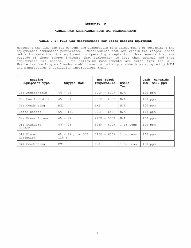
APPENDIX C
TABLES FOR ACCEPTABLE FLUE GAS MEASUREMENTS
Table C-1: Flue Gas Measurements for Space Heating Equipment Measuring the flue gas for content and temperature is a direct means of determining the equipment’s combustion performance. Measurements that are within the ranges listed below indicate that the equipment is operating acceptably. Measurements that are outside of these ranges indicate that combustion is less than optimal and that adjustments are needed. The following measurements are taken from the ODOD Weatherization Program Standards which use the industry standards as accepted by ANSI and manufacturer installation instructions (PMI). Heating Equipment Type
Oxygen (O2)
Net Stack Temperature
Smoke Test
Carb. Monoxide (CO) max. ppm
Gas Atmospheric
4% - 9%
300F - 600F
N/A
100 ppm
Gas Fan Assisted
4% - 9%
300F - 480F
N/A
100 ppm
Gas Condensing
PMI
PMI
N/A
100 ppm
Space Heater
5% - 15%
300F - 650F
N/A
100 ppm
Gas Power Burner
4% - 9%
275F - 550F
N/A
100 ppm
Oil Standard Burner
4% - 9%
325F - 600F
1 or less
100 ppm
Oil Flame Retention
4% - 7% , or CO2 11% +
325F - 600F
1 or less
100 ppm
Oil Condensing
PMI
PMI
1 or less
100 ppm
C-1

Table C-2: Flue Gas Measurements For Water Heating Equipment As with space heating equipment, measuring the flue gas content and temperature of water heaters is a means of determining the equipment’s combustion performance. Measurements that are within the ranges listed below indicate acceptable performance. Measurements that are outside of these ranges indicate that combustion is less than optimal and that adjustments are needed. The measurements are taken from the ODOD Weatherization Program Standards which use the industry standards as accepted by ANSI. DHW Unit Type
(O2) Oxygen
Net Stack Temperature
Smoke Test
(CO) Carbon Monoxide Max. Ppm
GAS (natural gas, propane, Atmospheric
4 - 9 %
300-600 degrees Fahrenheit
N/A
100
Fan Assisted
4 - 9%
300- 480 degrees Fahrenheit
N/A
100
OIL Standard Oil burner
4 - 9%
325 - 600 degrees Fahrenheit
1 or less
100
Flame Retention
4 - 7 %
325- 600 degrees Fahrenheit
1 or less
100
C-2

APPENDIX D CALCULATIONS FOR DETERMINING SEASONAL
HEAT LOSS AND PAYBACK This appendix is intended to provide a mechanism for determining the cost-effectiveness of installing insulation in cases when there is doubt. In most cases, insulation is cost-effective and the RRS has set standards for attic, wall and floor R-values. However, there may be instances when the cost-effectiveness of adding insulation is not clear. For example, there may be a question whether adding more insulation to an already insulated space is economically worthwhile. Or, the same doubt may exist when any one of a number of factors exist, such as: low fuel cost, high installation cost, small area, etc. Several things must be known before the calculation can be completed: 1, The R-value (measurement of heat flow resistance) of the materials in the area in
question; 2. The U-value (measurement of heat flow) of the materials in the area in question.
U-value is the reciprocal of R-value and represents the number of BTUs/hr./sq. ft. flowing through the material;
3. The Heating Degree Days (HDD) for the locality. HDDs represent the number days
the outdoor temperature is below 65 F times the number of degrees difference between 65 F and the actual outdoor temperature. HDDs are generally averaged over 30 years and are available for large cities. For Ohio, Cincinnati has approximately 4,410 HDDs, Columbus approximately 5,660 HDDs, Cleveland approximately 6,351 HDDs, Akron approximately 6,037 HDDs, Dayton approximately 5,622 HDDs, Mansfield approximately 6,403 HDDs, Toledo approximately 6,491 HHDs and Youngstown approximately 6,417 HDDs;
4. The size (square foot area) of the area in question; and 5. The cost of the fuel per unit (dollars per gal, cents per therm, cents per kWh,
etc.). STEP 1: Calculating Seasonal Heat Loss Without Insulation Complete the following formula:
U x A x T x 24 = Q Where: U = the U-value of the building materials (Btus/hr/sq.ft.)
A = the surface area of the building materials (sq.ft.) T = HDDs 24 = the number of hours in one day Q = the total annual amount of heat loss (Million Btus or therms)
STEP 2: Calculating Seasonal Heat Loss With Insulation Repeat the formula in Step 1 using the U-value that would exist assuming the building component is insulated.
D-1

STEP 3: Calculating Energy Savings and Dollar Savings
a. Subtract the amount of annual heat loss calculated after insulation (the result of Step 2) from the amount of annual heat loss calculated before insulation (result of Step 1). The result is the amount of energy that will be saved each year (Million Btus or therms).
b. Multiply the amount of energy saved by its cost. The result is the amount
of money that will be saved each year. STEP 4: Calculating Payback and Annual Return
a. Multiply the cost to install one square foot of insulation by the total number of square feet of area to be insulated. The result is the total cost of the insulation work.
b. Divide the amount of money saved (the result of Step 3, b) into the total
cost of the insulation work (the result of Step 4, a). The result is the number of years it will take for the annual savings achieved by the insulation to off-set the additional cost to install it. After that time, the savings will accrue to the owner.
c. For the annual rate of return, divide the cost of the insulation work by
the money saved.
D-2

APPENDIX E
GUIDELINES FOR SIZING WATER HEATERS AND CALCULATING PAYBACK
This appendix is offered as a guide for selecting an appliance which will meet the needs of the household efficiently and economically. Two approaches are offered. One approach is to simply use Table 3301.2 in CABO Chapter 33. Table 3301.2 provides recommended water heater storage capacity, BTU/hr input, draw and recovery rates based on the number of bathrooms and bedrooms present in the home. A sample portion of the information found in Table 3301.2 is provided below:
Dwellings with 1 to 1 and 1/2 Bathrooms
Type of Fuel Gas
Electric
Oil
Gas
Electric
Oil
Number of Bedrooms
2
2
2
3
3
3
Storage (gals)
30
30
30
30
40
30
Input (BTU/hr or kw)
36K
3.5
70K
36K
4.5
70K
Draw (gph)
60
44
89
60
58
89
Recovery (gph)
30
14
59
30
18
59
Dwellings with 2 to 2 and 1/2 Bathrooms
Type of Fuel Gas
Electric
Oil
Gas
Electric
Oil
Number of Bedrooms
3
3
3
4
4
4
Storage (gals)
40
50
30
40
50
30
Input (BTU/hr or kw)
36K
5.5
70K
36K
5.5
70k
Draw (gph)
70
72
89
72
72
89
Recovery (gph)
30
22
59
32
22
59
Another approach is to use the procedure outlined in the GAMA Consumer’s Directory of Certified Energy Ratings. This approach is more exact in that it condsiders estimated water usage to determine the right “size” equipment. Also, it includes methodology for estimating and comparing the operating costs of equipment in order to select the most cost-effective appliance. Before completing the steps, there are several things that must be known: 1. The number of plumbing fixtures in the dwelling 2. The number of occupants in the household and their general use patterns. This is
critical in order to establish the time of day and the frequency that hot water is used. For example, when are baths or showers taken, clothes washed and dishes washed? The purpose of this is to establish the peak demand for the first hour of usage.
E-1

3. The Energy Factor (EF) of the models of water heaters being considered for installation. This information is available in the GAMA directory for those manufacturers participating in the certification program.
4. The cost to install the models of water heaters being considered. STEP 1: Estimating Peak Hour Demand (Sizing the Water Heater)
a. Multiply the number of activities using hot water during the busiest hour of the day times the estimated average number of gallons used per activity. Some activities and estimated average usages are; bath/shower - 20 gals., shaving - 2 gals., hand/face washing - 4 gals., shampooing - 4 gals., hand dishwashing - 4 gals. and automatic clothes washing - 32 gals.
b. Add the estimated average usages for the first hour. The result is the
household’s peak first hour demand.
c. Select models of water heaters that have a peak first hour demand rating that is close (give or take 2 gals./hr) to the peak first hour demand for the household. This information is available in the GAMA directory.
STEP 2: Calculating Payback
a. Determine the water heater’s estimated annual operating cost by using the chart provided in the GAMA directory. Find the chart for the appliance’s fuel. Find the column for the appliance’s EF. Find the row for the appropriate fuel cost. Follow the row across to the intersection of the EF column. The result is the appliance’s estimated annual fuel operating cost. Repeat for each model to be considered.
b. Subtract the installation cost of the higher EF model from the
installation cost of the lower EF model. This is the amount of additional costs required to buy and install the higher EF model.
C. Subtract the annual estimated operating cost of the higher EF model from
the estimated annual operating cost of the lower EF model. This is the amount of money the higher EF model will save each year of operation over the lower EF model.
d. Divide the annual savings (from Step 2, c) into the additional costs (from
Step 2, b). The result is the number of years before the savings generated by the higher EF model will off-set the increased cost of installing the higher EF model. After that time, the savings will accrue to the owner.
E-2

F-1
APPENDIX F SUMMARY OF ELECTRICAL REQUIREMENTS This appendix is provided as a quick reference for fixture and receptacle location, GFCI receptacle location, mechanical execution of work requirements and a general description of what constitutes the electrical system. It is provided only as a supplement to the requirements outlined in the RRS, CABO and the NEC. OHCP advises grantees to refer to the codes for a detailed description of the requirements.
ELECTRICAL SYSTEM COMPONENTS
ELECTRIC SERVICE
An electric service is required for all buildings containing an electrical system and receiving electrical energy from a utility company. The main electrical power line to your house is called the service Exterior Service and Meter: From the transformer, the power company brings electricity into a home via overhead wires or underground cables. In most localities the exterior service from the pole to the meter, including the meter and base, belongs to the power company and is maintained by the power company. The overhead wiring that swings from the utility pole to the house is called the service drop or triplex (three wires spice into the service cable). The power company and local inspectors will have specific requirements for the location and placement of the service drop and the point of attachment, therefore, coordination and preplanning will be required to meet these requirements. Service Entrance: The utility’s wires are spliced to the service entrance wires, which are usually encased in metal tubing called conduit, or combined in a thick insulated wire called service entrance (SE) cable. In an overhead service entrance, the utility’s wires may be attached directly to the house with nonconductive insulators (porcelain) or to an approved mast, which is a galvanized pipe that rises above the roof and continues downward to the meter. There should be a weather head/goose neck or service head and loosely draped wires (drip loop). In both types of installation the entrance head is higher than the incoming wires to prevent water from draining into the electrical system. From the service head, the wires pass through the meter, which records the electricity usage, and into the main service panel. The service entrance always ends at the service panel.
Service Panel: The panel board or load center is the distribution point for all electrical power brought into the house. The service panel is also known as the fuse box, circuit breaker panel, main, or service equipment. Branch circuits in the service panel provide power for three types of circuits-20 amp general lighting circuits, 20 amp small appliance circuits, and 20-70 amps for individual appliances or special circuits. Branch circuits are designed to carry only a certain amperage. Each circuit is protected at the service panel by an overcurrent protection device, either a fuse or a circuit breaker which stops the flow of current by tripping or blowing when this rating is exceeded. All new installations of service panels or modifications to existing panels shall conform to NEC Article 230. Premises Wiring System: The premises wiring system begins at the load end of the service drop (drip loop or service head) or the load end of the underground service lateral and ends at the outlet. This includes interior and exterior wiring, outside branch circuits and feeders installed on or between buildings that supply energy to motors, lighting and controls, and signal circuit wiring that are combined or used with any hardware, fittings, and wiring devices that may be temporarily or permanently installed.

SYSTEM INSPECTION RRS requires that each electrical system be inspected and evaluated to determine the safety, capacity and convenience needs of the electrical system. In order to determine the scope of work for the written specifications so that the system complies with the NEC and the RRS, a thorough evaluation must be conducted. The following is a series of questions and statements to guide you in conducting an assessment. These items are meant to serve as a minimum when assessing the condition of housing unit’s electrical system and to determine the need for a complete service upgrade, a total replacement of all interior wiring versus modernizing the system by adding new circuits and outlets to the existing equipment. OHCP recommends beginning with an assessment of the exterior wiring and power supply sources because most often the interior wiring has been altered, but the service has not. The assessment of the exterior wiring should answer the following questions:
a. Is the service drop a 3-wire system and are the wires properly rated for the location? If not, the service drop shall be replaced. The service drop shall be a 3-wire system with two insulated hot wires twisted around a bare, stranded, grounded neutral wire. The service conductors shall have adequate mechanical strength and be sized to carry the load without an increase in temperature rise. The wire shall be rated for wet locations such as; TW, RHW, THW or any type wire suitable for a wet location. Two-wire systems which fail to meet grounding requirements, improperly rated service drop wire and services which pass through another building or structure shall be priorities for replacement.
b. Is the service drop clear of traffic, obstructions and hazards? If not,
proper clearances should be created. The service drop should be a minimum of 10 ft. over pedestrian areas, 12 ft. over driveways and/or 18 ft. clearance over public streets. Also, the wires should be free from obstructions and hazards such as tree limbs.
c. Is the location where the service entrance wires connect to the unit
(point of attachment) secure and weatherproof? If not, the connection shall be made secure and weatherproof. The service entrance wires should be connected by a porcelain insulator which is securely bolted to a solid material and the cable should be physically protected from the weather (i.e. insulated exterior rated wire, installed in conduit or pipe).
d. Is the service entrance securely attached to the house and properly clear
of openings and walkways? If not, the service entrance shall be made secure and clear of hazardous locations. The service entrance should be securely attached 2-3 ft. above the service head with a drip loop, goose neck or mast in a manner to permit water to drain off the service head and not into it. It should be clamped and have a 3 ft. clearance from the sides of doors, porches, decks, balconies and the bottom of windows that open.
e. Is the meter base properly secured and connected to a hub with a
watertight connector? Are the service entrance (SE) cable and the meter base ratings the same amperage? Remember, the rating of the SE cable, the meter base and the service panel must all match. If not, the meter base shall be made secure, weather tight and of consistent amperage.
F-2

f. Is the system properly grounded by a bare copper or green insulated copper ground wire connected at the panel to a ground rod? Is the grounding connection made to the same grounded conductor at the transformer that supplies the system? If not, the system shall be properly grounded. The electrical system shall be grounded to a metal water pipe, well casing or an 8' metal grounding rod.
The building should be bonded to form a grounding electrode system which is two or more grounding electrodes effectively bonded together such as the service panel and a grounding rod, or a reinforcing rod or a grounding ring. For grounding requirements, see NEC Article 250-81.
g. If an exterior mounted service panel is present, is the panel rated for
exterior use and is the panel weather tight? If not, the service shall be replaced with an exterior rated panel (Type 3-R) or moved to an interior location. Where feasible, OHCP recommends relocating exterior mounted service panels to an interior location such as a utility room, enclosed porch or basement.
h. Is exterior wiring properly installed, properly rated and free from
hazards? If not, the wiring shall be made safe. All exposed exterior wiring shall be rated UF sunlight resistance. All exterior receptacles shall be GFCI protected and installed in exterior rated boxes with weather tight covers. Wiring which serves garages and structures attached to the dwelling shall be free from hazards.
After an inspection of the exterior wiring has been conducted and noted, an assessment of the service equipment and related wiring must be done. OHCP recommends beginning at the service panel which is also known as the breaker panel, fuse box, or main. The following items are to be thoroughly noted to assess the safety, capacity and convenience of the system as well as determining the need for replacement of or addition to the existing panel. The assessment of the service equipment should answer the following questions:
i. Does the service panel have overcurrent protection devices and a main
disconnect? If no main disconnect exists, there shall be no more than 6 switches or circuit breakers used as disconnecting means. The panel shall be marked “service equipment” with the name of the manufacturer, panel rating and label or listing clearly visible; and shall have circuit breaker or fuse overcurrent protection devices with a clearly marked main disconnect. If not, the panel shall be replaced.
j. Is the service panel rated at the proper amperage and are all available
spaces filled with fuses or circuit breakers? If so, the panel shall be replaced. Service panels shall be rated at least 100 amps and 120/240 volt single phase with a grounded neutral, and for the same amperage as the meter base and the SE cable. Additional spaces should be available for future expansion.
k. Is the panel in a proper location with adequate clearance and light? If
not, the panel shall be moved or otherwise provided with proper clearance and light. Panels shall be located in dry areas with adequate artificial lighting and at least a 3 ft deep, 30 inch wide and 6 ½ ft high working space with room to fully open the panel door. Panels located in bathrooms or in closets shall be relocated. Panels located on the exterior shall be rated Type 3-R; however, relocation for convenience of the resident is encouraged.
F-3
l. Is the panel in good condition, securely attached to the dwelling, and free of obstructions? If not, the panel shall be properly secured and obstructions removed. Panels shall be securely attached to a wood backing, such as plywood, or recessed between stud wall framing with a cover that securely latches.
The panel shall be free of missing knock out plates and all open slots or spaces shall be properly sealed. Materials such as paint, plaster, cleaners or abrasives shall not be stored on or in the panel. The space above the panel should be reserved only for related wiring and be free of heating ducts and other obstacles.
m. Are there an adequate number of properly sized and labeled circuits with
at least 4 available full size spaces? If not, the proper number of labeled circuits shall be provided and the panel shall have the capacity for installation of additional circuits for future expansion. The system shall contain at least two 20 amp small appliance circuits, and at least one 15 amp lighting circuit for each 500 square feet of floor space within the unit. The bathroom and laundry shall each be on a separate 20 amp circuit. Major appliances such as the water heater, range and clothes dryer shall be on an individual dedicated circuit.
n. Does the panel contain overcurrent protection devices which exceed the
circuit capacity? For example, does a 15 amp rated circuit have a 20 amp fuse, or have full size breakers been replaced with tandem (half-size or dual) breakers and do these replacements exceed the panel rating? If so, the improper overcurrent protection devices shall be replaced.
o. Are the circuits properly sized to carry the load they serve? If not,
the circuits shall be made to carry the proper load (i.e. #12 wire for a 20 amp circuit, #10 wire for 30 amp circuit, etc.). The wire shall have insulation suitable for the voltage, temperature and location (wet, etc). The wire ampacity rating shall be sufficient to avoid voltage drop over 3% of the branch circuit rating, as noted in NEC Tables 310-16 through 310-19. Circuits which serve appliances or fixtures for longer than three hour periods shall not have a load which exceeds 80% of the rated circuit capacity.
p. Is there any evidence of overheating, arcing or failure indicating short-
circuits, overloads and potential for fire (e.g. black marks, scorching, etc. Are the terminals in deteriorated condition or corroded? If so, the source of mal-function, hazard or deterioration shall be corrected and the panel replaced as needed.
q. Is the panel and service properly grounded? If not, proper grounding
shall be created. The ground wire, either bare copper or green insulated copper, shall be connected to the panel’s neutral bus bar. If applicable, the service shall be grounded by a bare copper wire connected to an underground metal cold water pipe or well casing; or to the street side of the meter bonding with a jumper wire clamped on both sides of the meter. Remember, the panel is the “bulls eye” of grounding and must be properly grounded in an approved manner to complete the circuit and return to ground.
The condition of the interior wiring, as well as the installation methods, is the third step in the assessment of the electrical system.
F-4

If the panelboard terminals and circuits have been overloaded for long periods of time and wires are in deteriorated condition with loose connections, chances are the insulation on the concealed wiring might also be deteriorated and unsafe. Inspecting the interior wiring, particularly in attic areas and basements, should give a good indication of the condition of the wiring concealed within the walls, and will permit viewing the installation methods and mechanical execution of work. This should note if non-professional installation is prevalent and assist with assessment of potential hazards. The assessment of the interior wiring should answer the following questions:
r. Is the insulation on the accessible ends of the old wiring brittle? Have
cables been improperly spliced to old knob and tube wiring? Have circuit extensions been made with flexible or zip cord in lieu of permanent wiring?
Has improper splicing (such as without junction boxes) been made in existing cables? If so, the hazards shall be corrected and wiring should be replaced throughout the unit. Existing premises wiring that has aluminum conductors shall be replaced.
s. Are other non-professional installations or alterations present, such as
loose, hanging or drooping sections of wire (not stapled to joists or run through drilled holes); fixtures hanging by wire rather than being securely connected to walls or ceilings, or joists; wire with cracked or missing insulation (particularly exposed knob and tube wire near loose insulation); and wires laying on hot water pipes. Are closet light fixtures open lamp style located in close proximity to flammable materials? If so, the hazards shall be corrected. If there is alot of non-professional work present, a total re-wiring of the house (rather than repairing the numerous problems) may be the best solution.
t. If the existing wiring is in proper condition (e.g. good insulation and
properly spliced), the chances are it can be left in service, especially if recently added appliances can be disconnected from existing circuits and reconnected to new circuits installed for that purpose. Additional circuits should be added for both 240 volt and 120 volt appliances for which no wiring was originally provided. However, additional receptacles can be safely added to some existing circuits without overloading the circuits when no additional load will be imposed where they are for convenience only and will be used for the same existing portable appliances.
u. Are switches and receptacle outlets safe and securely fastened to the
walls? Are switches located behind the door or receptacles located in tub/shower areas or other damp or wet locations? Are switches or receptacle outlets loose or and missing plate covers? If so, the appropriate repairs shall be made. Floor outlets shall be installed in an approved box listed and labeled for floor receptacle use or they shall be removed. All receptacles shall be tested for grounding and if the wiring is a 2-wire ungrounded type, replacement of the two-wire ungrounded wiring with three-wire grounded wiring is recommended to enable installation of grounded receptacles.
v. Are the number of receptacles in the bathroom and kitchen adequate and are
outlets GFCI-protected, as required? If not, additional receptacles shall be added and GFCI-protected receptacles shall be installed where required.
F-5
w. Is each receptacle rated to match the circuit breaker and wire size? Are they properly sized, not overloaded and are any 3-wire grounded receptacles installed on the old 2-wire ungrounded system? If so, the proper replacements shall be made, including replacing old 2-wire ungrounded receptacles with new 2 wire ungrounded receptacles.
x. Have the holes bored through studs and joists for wiring runs, weakened
the structural integrity of the framing members? Are there an excessive number of wires bundled in the holes so that heat friction could cause possible fire hazards.
If so, the framing members shall be reinforced and the number of wires bundled in the spaces shall be reduced. New holes bored through floor joist shall conform to CABO Sections 502.6 and 502.7 and new holes bored through wall studs shall conform to CABO Section 602.5.
MECHANICAL EXECUTION OF WORK Section 110-12 of the NEC covers the “Mechanical Execution of Work” and requires a neat and workmanlike installation of all electric equipment. “Equipment includes materials, fittings, devices, appliances, fixtures, apparatus, and the like used as part of, or in connection with an electrical installation”. Some examples of mechanical execution of work include the following: 1. Effective closing of unused openings in outlet, device, pull and junction boxes,
conduit bodies and fittings, raceways, auxiliary gutters, cabinets, equipment cases or housings.
Note: Any unused opening must be effectively closed with knockout seals or other materials that will provide substantial protection that is equivalent to that of the wall of a box or piece of equipment, for example.
2. Conductor insulation not damaged, including nicked wires at the ends of their
terminations. 3. Cable assemblies not kinked or with excessive bends that are sharper than the
permitted radius.
Note: Bends in cable assemblies must not have a radius that is less than five times the diameter of the cable. See NEC Sections 338-8 and 336-14.
4. Staples used to secure cables assemblies not driven too tightly, In some cases
insulate types of staples may provide better protection against damage. 5. All terminations made in accordance with the manufacturers’ instructions provided
on the equipment. 6. Use of proper tools for bending raceways. 7. Making sure all equipment is cleaned both inside and outside before it is
energized. 8. Verifying that connections of all metal electrical cables, raceways, and
equipment will result in compliance with rules pertaining to grounding continuity.
9. Protection against physical damage for exposed electrical equipment during and
after construction.
F-6

Note: NEC Section 110-12C requires that electrical equipment be protected from damage by other trades during construction.
Fixture and Receptacle Location Requirements Kitchen 1. All kitchen receptacles shall be on a three wire grounded 20 amp circuit and
shall be GFCI protected unless for a dedicated appliance on a dedicated circuit (see NEC Article 210-8(a)(5)b).
2. Receptacle outlets shall be installed at each kitchen wall counter space 12
inches or wider and shall be installed so that no point along the counter line is more than 24 inches from a receptacle outlet in that space (see NEC Article 210-52)
3. Two 20 amp small appliance branch circuits serving only the kitchen are required.
The number of small appliances shall be taken into consideration when planning the circuit loads and placement of the outlets to avoid overloading and the use of extension cords or temporary multiplex outlets.
4. A permanently installed overhead lighting fixture controlled by a wall switch is
required. 5. Appliance outlets installed for a specific appliance, such as a refrigerator,
must be installed within 6 feet of the specific appliance. Bathroom 1. The bathroom shall be required to have at least one receptacle outlet, which
shall be GFCI protected, and shall be located at least thirty (30) inches and not more than 48 inches above the floor adjacent to the lavatory and not more than four feet from the lavatory and at least twelve inches from the outer rim of any bathtub or shower opening.
2. A permanently mounted switch controlled ceiling or wall lighting fixture is required which is not to be power from the dedicated bathroom 20 amp circuit. No hanging fixture or lighting track can be located over the tub unless it is over 8 feet and cannot be located within 3 feet of the outside of tub.
3. Exhaust fans shall include a closure device that seals the duct when the fan is
not operating. Ducts shall lead directly to the outside air (see ducting requirements noted in RRS Section 2.8.1.
A fan/light combo shall operate independently of each other, each having a separate grounded control switch. New exhaust fans shall be properly sized to change the volume of air in the bathroom every 12 minutes. Exhaust fans should be certified to operate at a Cubic Feet per Minute (CFM) capacity to sone rating of no lower than 10 CFM per sone.
Laundry Room/Area 1. Every laundry room or laundry area shall have a receptacle outlet on a separate
20 amp circuit (see NEC Article 220-4c). Note that the clothes dryer is not considered part of the laundry circuit, the dryer requires an independent appliance circuit.
F-7
2. The laundry room/area shall have a lighting fixture controlled by a wall switch. Unfinished Basement and Garage 1. Outlets installed in unfinished basements and or crawl spaces shall be GFCI
protected (see NEC Article 210-8 (a) (4). Exception- a receptacle located in a dedicated space for an appliance, such as a washing machine, or receptacles not readily accessible. A GFCI receptacle is required in the unfinished basement in addition to the laundry outlet.
2. Every basement shall have at least one switch controlled light fixture and one
general purpose outlet. When installing a new light fixture safety should be a prime consideration, and the fixture should provide a means of protection for the bulb.
3. Every attached garage (and detached garages with power), shall have at least one
receptacle outlet which is to be GFCI protected. Existing wiring in garages shall be free of Electrical hazards. Placement of outlets in garages at least 48" above floor is recommended.
Attic and Crawlspace A permanent electric light fixture and outlet shall be installed when access to equipment, such as furnaces, is needed. The light shall be controlled by a switch located at the passageway opening. Equipment 1. Furnaces and Air Conditioning equipment should have their own electrical
disconnects which are within sight of and readily accessible from equipment for which it is intended and are of correct amperage and installed in accordance with all relevant NEC provisions. Thermostats for heating and cooling equipment shall be operable and properly wired to equipment with all wires properly concealed. Wiring for room air conditioners shall conform to NEC Article 440-60 thru 64.
2. A permanent electrical receptacle and lighting fixture shall be provided near all
heating appliances located in enclosed rooms, attics and crawlspaces. 3. Electrical circuits for well pumps (jet pumps or submersible pumps), sump pumps,
and septic aerators shall be in accordance with NEC requirements.
Ground Fault Circuit Interrupter Protection Required per NEC Article 210-8(a)
All 15 amp and 20 amp receptacles installed in the locations specified below shall haveground-fault circuit interrupter (GFCI) protection for personnel. 1. Bathrooms 2. Garages. (except inaccessible receptacles such as door openers or dedicated space
for appliance that in normal use is not easily moved such as a freezer or refrigerator.)
3. Unfinished Basements. (Except inaccessible receptacles, and a single or duplex
receptacle for two appliances located within dedicated space for each appliance that in normal use is not easily moved from one place to another, and that is cord and plug connected in accordance with Article 400-7 (a) (6), (a) (7), or (a) (8).
F-8
Receptacles installed under exceptions to Section 210-8 (5) shall not be considered as meeting the requirements of Section 210-52 (g) which states that at least one receptacle outlet, in addition to any provided for laundry equipment, shall be installed in each basement and in each attached garage, and in each detached garage with power.
4. Outdoors 5. Crawlspaces. (at or below grade level) 6. Kitchens. Receptacles installed to serve counter top surfaces. 7. Wet bar sinks.
F-9

APPENDIX G
GUIDELINES FOR SIZING PLUMBING SUPPLY LINES Following is a simplified procedure for helping to determine the adequacy of existing water supply lines and in the sizing of new water supply lines. For this method to be reasonably accurate the water pressure at the main shut-off valve where the water comes into the building must be within the range specified in 5.2.2.1 (40-80 psi) and the elevation of the highest fixture above the service valve must be less than 25 feet. For more detailed, more accurate methodology or for systems outside the above parameters the following references might be useful: OPC Appendix E, CABO Appendix C; Practical Plumbing Engineering by Cyril M. Harris, and Do-It-Yourself Plumbing by Max Alth (see the bibliography for complete listings). Other variables such as age of piping, number and type of fittings, and design of fixtures also affect the pressure. For this reason no formula or procedure can account for all variables and be fully relied upon to fit every situation, but must be augmented with actual field testing and experience. However, this procedure can serve as a basic guideline for proper sizing of water supply piping. Following are the steps in the process: 1. For each pipe interval, determine the fixture load that it carries using Table G1
(for multiple fixtures use the guidelines set out below).
A. Only count hose bibs at 50% when adding to the total load. B. When combining three or more fixtures (not fixture groups), multiply by
.9. C. When combining one or more fixtures with a fixture group, multiply by .9. D. When combining two fixture groups multiply by .8. E. When combining three or more fixture groups or two or more fixture groups
+ one or more fixtures multiply by .7. F. Use fixture groups when possible.
TABLE G1 Water Demand of Fixtures and Fixture Groups in Gallons Per Minute Fixture Type Or Group
Total
Hot
Cold
Lavatory Faucet
2
1.5
1.5
Bathtub Faucet Or Shower Head
5
4
3.5
Toilet Tank
3
3
Kitchen Sink
4
3
3
Dishwasher
4
4
Laundry Tub
5
3.25
3.25
Washing Machine
5
3.5
4
Hose Bib
5
5
Kitchen Group (Sink and Dishwasher)
7
5.5
3*
Laundry Group (W. M. And L. Tub)
8
6
6.5
1/2 Bath Group (Lavatory and Toilet)
4.5
1.5*
4
G-1

Water Demand of Fixtures and Fixture Groups in Gallons Per Minute Full Bath Group (Lav., Toilet, Tub/Sh.)
8 5.5 7
1 1/2 Bath Group
9.5
7
7.5
2 Bath Group
12
9.5
8.5
2 1/2 Bath Group
13
10
9
3 Bath Group
15
11.5
10
* Really a single fixture and not a fixture group. 2. Determine the type of piping that was or is to be used. 3. Using Table G2 below determine the size of the piping necessary to carry the
amount of demand from the calculations above.
TABLE G2
PIPE SIZING BASED ON VELOCITY LIMITATION1
Flow of pipe in gallons per minute2
Copper Water Tube3
Nominal
Pipe Size (Inches)
Type K
Type L
Type M
CPVC4 or
Polyethylene5
Steel Pipe6
1/2
5.4
5.8
6.3
7.6
7.6
3/4
10.9
12.1
12.9
13.3
13.3
1
19.4
20.6
21.8
21.5
21.5
1 1/4
30.3
31.3
32.6
37.3
37.3
1. Pipe sizing based on velocities of 8 feet per second to avoid excessive noise in
system; shock damage to pipe, fittings, and equipment; and accelerated corrosion. 2. Actual flow also depends on the roughness of the pipe and the amount of mineral
deposition inside the pipes, which will vary with the age of the pipe and the water quality, especially with galvanized pipe.
3. Flow rates are based on copper water tube which conforms to ASTM B 88. 4. Flow rates are based on chlorinated polyvinyl chloride pipe, schedule 40, which
conforms to ASTM F 441. 5. Flow rates based on polyethylene pipe, schedule 40, which conforms to ASTM D
2447. 6. Flow rates based on galvanized steel pipe, schedule 40, which conforms to ASTM A
53.
G-2

H-1
APPENDIX H SUMMARY OF INSPECTION AND TESTING REQUIREMENTS This appendix lists eight specialized, but routine, inspections and tests that the RRS requires. This list is provided as a reference and it is not intended to outline all of the inspections which may be needed to thoroughly assess a rehabilitation project. 1. Wood-boring Insect Infestation and Damage
Each building shall be inspected for evidence of wood-boring insect infestation and damage.
2. Well Water Quality
If potable water is supplied by a private well located on the premises, the quality of the water must be tested by the local health department or other qualified source. At a minimum, the test must determine if the bacterial content of the water is within safe limits.
3. Private Septic System
If sewage is treated by a private septic system located on the premises, the septic system must be inspected by the local health department or other qualified source. The inspection must determine if the system is adequate, functional and properly treating the discharged waste.
4. Plumbing System
The plumbing system (including the water supply lines and the drain, waste and vent lines) shall be inspected for evidence of leaks, hazardous conditions, improper materials, improper installations, inadequate service and other existing or incipient conditions needing repair or improvement. The inspection must also assess the condition and adequacy of the plumbing fixtures and plumbing appliances.
5. Electrical System
The electrical system (including the exterior service, service entrance, service panel and premises wiring) shall be inspected for evidence of hazardous conditions, improper materials, improper installations, inadequate service and other existing or incipient conditions needing repair or improvement. The inspection must include a load calculation and determine the number of circuits required.
6. Space Heating Equipment
The space equipment, including the fuel/power source, the venting system and the heat distribution system, shall be inspected for evidence of hazardous conditions, improper materials, improper installations and other conditions or problems needing repair or improvement. If the equipment is to be replaced, the inspection must include a heat load calculation to size the new equipment. If fuel-fired equipment is not to be replaced, the inspection must include flue gas measurement and stack temperature tests to determine combustion safety and efficiency.
7. Water Heating Equipment
The water heating equipment, including the venting system, shall be inspected for evidence of hazardous conditions, improper materials, improper installations and other conditions or problems needing repair or improvement. If equipment is to be replaced, the inspection must include a calculation to size the new equipment. If fuel-fired equipment is not to be replaced, the inspection must include flue gas measurement and stack temperature tests to determine combustion safety and efficiency.
8. Fuel-gas Piping
If fuel-gas (i.e. natural gas or LPG) is used, the lines shall be inspected for evidence of hazardous conditions, improper materials and improper installations. Also, the lines shall be tested for leaks.
H-2

I-1
APPENDIX I
ABBREVIATIONS
ACCA Air Conditioning Contractors of America ANSI American National Standards Institute ASHRAE American Society of Heating, Refrigeration & Air Conditioning Engineers ASSE Americal Society of Safety Engineers ASTM American Society for Testing and Materials BOCA NPMC Building Officials & Code Administrators of America, National Property
Maintenance Code CABO Council of American Building Officials, One and Two Family Dwelling Code CABO MEC Council of American Building Officials, Model Energy Code CSA Canadian Standard Approval EPA Environmental Protection Agency (includes federal and state agencies) FEMA Federal Emergency Management Agency GAMA Gas Appliance Manufacturers Association HUD U.S. Department of Housing and Urban Development NFPA National Fire Protection Association ODH Ohio Department of Health OHCP Office of Housing & Community Partnerships OHPO Ohio Historic Preservation Office OPC Ohio Plumbing Code OSHA Occupational Safety & Health Administration UFAS Uniform Federal Accessibility Standards UL Underwriter’s Laboratory

APPENDIX J DEFINITIONS Attic That portion of a building which is between the roof and the ceiling
of the top floor. In 1 1/2 story buildings, the attic includes the area behind the kneewall.
Basement That portion of a building which is partly or completely below
grade. Basements are enclosed by the foundation walls and may be habitable or unhabitable. In general, basements have sufficient headroom to enter and move about.
Bathroom A room containing plumbing fixtures including a bathtub, shower or
combination bathtub/shower. In most single-family residential dwellings, the bathroom will also contain a toilet (water closet) and a lavatory. However, in the context of the RRS, a room containing a toilet and a lavatory (i.e. a “toilet room”) shall also be considered a bathroom.
Bedroom A room designated for sleeping. In most single family residential
dwellings, bedrooms are separate rooms used exclusively for sleeping. However, in the context of the RRS, other habitable rooms (e.g. living room, dining room, parlor, den, etc.) which are used for sleeping shall be considered bedrooms.
Blower Door A calibrated device consisting of a high velocity fan, pressure
sensitive gauges and a simple computer used to pressurize (or de-pressurize) a dwelling and therefore quantify and locate air movement.
Building The structure containing the dwelling or dwellings and the common
areas within the structure. Building Shell The building’s wall, ceiling and floor assemblies that make up the
exterior boundaries. Regarding energy efficiency measures, the building shell refers to the boundaries between the conditioned and unconditioned spaces (i.e. thermal boundaries).
Cellar A basement space which is unfinished and unhabitable. In many
cases, cellars have dirt, stone or brick floors. Combustion Equipment or appliances that produce heat by the on-site Equipment burning of gaseous, liquid or solid fuel. Examples of combustion
equipment include; furnaces, space heaters, fireplaces, water heaters, ranges, cook top stoves and clothes dryers. Combustion equipment may also be referred to as fuel-burning equipment.
Conditioned Those portions of a building in which the air is heated (or
cooled) to maintain comfort for the occupant and/or to protect the building’s systems, such as protecting water lines from freezing. In the context of the RRS, conditioned spaces are generally spaces which are intentionally heated (or cooled) and therefore are within the building’s thermal boundary. Spaces which are unintentionally conditioned, such as a furnace room or a basement with ducts running through it, shall be considered unconditioned.
J-1

J-2
Crawlspace The space between the floor of the building and the grade below. Crawlspaces may be enclosed by the foundation walls or open the outside.
Direct-Vent High energy efficient space and water heating equipment that, with
Equipment the aid of draft inducing fans, receive combustion air directly from the outside, burn fuel within a sealed combustion chamber and vent combustion by-products horizontally through the sidewall.
Dwelling or A single unit providing complete independent living facilities for
Dwelling Unit one or more persons including permanent provisions for living, sleeping, eating, cooking and sanitation.
Electrical In the context of the RRS, the electrical system shall include
System all components of the dwelling and premises wiring system, from the load end of the service drop (or underground lateral) to the receptacle or fixture. This includes the service entrance, the service panel and over-current protection devices, the wiring circuitry and the fixtures.
Functional In the context of the RRS, functional means that a thing operates or
fulfills the purpose for which it was designed and intended. Functional implies that the thing is in good repair and works without problems.
Fuel-Burning See “combustion equipment”. Generally refers to furnaces and water
Equipment heaters. Habitable Space Space within a dwelling designated for living, sleeping, eating or
cooking. Bathrooms, toilet rooms, closets, storage or utility rooms, halls, and similar spaces are not considered habitable spaces.
Heating The ducts or piping which conduct the heated air or fluid from the
Distribution heating equipment to the space and back to the heating equipment. System Warm-air distribution systems include the plenum, supply and return ducts, connectors, the fan and air handler components, registers and dampers. Hydronic distribution systems include supply and return piping, connectors, pumps, valves, expansion tanks and radiators.
Heating In the context of the RRS, heating equipment refers to
Equipment appliances designed and used exclusively for heating the space within the dwelling. Examples include furnaces, space heaters, boilers and baseboard heaters. Heating equipment may be fuel-burning or electric and stationary or portable. Other appliances that produce heat, but are not designed for space heating, such as kitchen ranges and cooktop stoves, are not considered heating equipment.
Hydronic System Hot water or steam heating equipment and distribution system. Kitchen A room designated for preparing food. In most single-family
residences, a kitchen is a separate room or distinct part of a room used exclusively for cooking. In the context of the RRS, a kitchen must have adequate space for a cooking appliance and a refrigerator, a sink and adequate storage and counter top space.
Kneewall A short stud wall connecting the floor and the roof framing members
which separates a room from an attic area.
J-3
Occupiable Space Space within a dwelling other than that designated for living, sleeping, eating or cooking. Occupiable spaces include areas such as bathrooms, toilet rooms, closets, halls, storage and utility rooms.
Primary Heating Heating equipment used as the main source for space heating.
Equipment Generally, primary heating equipment is permanent and stationary. Portable space heaters are generally secondary heat sources used as back up or in emergencies.
Plumbing System In the context of the RRS, the plumbing system shall include all
components of the water supply and sanitary disposal system in the dwelling unit and on the premises. The water supply system includes the supply (if a well is present), supply piping, connectors, water heater, valves and fixtures. The sanitary disposal system includes the drain, waste and vent pipes, traps, sewer connections and septic (if present).
Qualified Person Person demonstrating the knowledge, skill and experience required to
perform the work in accordance with the RRS or referenced code. Regarding electrical, plumbing and HVAC work, qualified may also mean a person who is certified or licensed, or whose primary occupation is in those residential trades.
Unconditioned Those portions of a building which are not heated (or not cooled).
Space In the context of the RRS, these areas are generally those which are intentionally not heated (or cooled).
Unhabitable The spaces in a building or a structure on the premises which
Space are not designed or built for habitation and therefore are inappropriate for residential living. Generally, unhabitable spaces are outside of the dwelling’s thermal boundaries. Examples of unhabitable spaces include; unfinished attics, basements, crawlspaces, garages, porches, sheds and other out-buildings.
Vapor Retarder A material that retards the passage of water vapor. Vapor retarders
must have a permeance rated at not greater than 1 perm. Commonly used vapor retarders include, 6 mil polyethylene sheeting and specialty paints.

APPENDIX K
CODE REFERENCES
BOCA National Property Maintenance Code Commentary. Building Officials & Code Administrators International, Inc. 1996. CABO One and Two Family Dwelling Code. The Council of American Building Officials. 1995. CABO Model Energy Code. The Council of American Building Officials. 1993. NFPA 31, Installation of Oil-Burning Equipment. National Fire Protection Association. 1992. NFPA 54, National Fuel Gas Code. National Fire Protection Association. 1992. NFPA 70, National Electric Code. National Fire Protection Association. 1996. NFPA 211, Standards for Chimneys, Fireplaces, Vents and Solid Fuel-Burning Appliances. National Fire Protection Association. 1996. Ohio Plumbing Code (Ohio Basic Building Code, Plumbing), Building Officials and Code Administrators International, Inc. 1998. BIBLIOGRAPHY Electrical Practical Electrical Wiring. 16th Edition. Richter, Herbert P. and Schwan, Creighton W. McGraw-Hill. New York. 1993. New Complete Do-It-Yourself Manual. Readers Digest Association, Inc. New York. 1996. Electrical Inspection Workbook. Henry, Tom. Henry Publications. 1997. Wiring A House. Cauldwell, Rex. The Taunton Press. Newtown, CT. 1996. One & Two-Family Dwelling Electrical Systems. Second Edition. Simmons, J. Philip. International Association of Electrical Inspectors. Richardson, TX. 1994. Residential Wiring. Markell, Jeff. Craftsman Book Co. Carlsbad, CA. 1987. Plumbing Practical Plumbing Engineering. Harris, Cyril M. McGraw-Hill. New York. 1991. Do-It-Yourself Plumbing. Alth, Max. Sterling Publishing Co. New York. 1987.
K-1
HVAC and Energy Efficiency Consumer’s Directory of Certified Energy Ratings For Residential Heating And Water Heating Equipment. Gas Appliance Manufacturer’s Association. 1990. Residential Energy. Second Edition. Krigger, John. Saturn Resource Management. Helena, MT. 1996. Weatherization Program Standards. Fifth Edition. Ohio Department of Development. Office of Energy Efficiency. 1996. Builder’s Guide: Cold Climate. Lstiburek, Joseph. Building Science Corporation. Energy Efficient Building Association. Minneapolis, MN. 1997.
K-2