Embed Size (px)
Citation preview

8/4/2019 Oil and Gas Drilling Task
http://slidepdf.com/reader/full/oil-and-gas-drilling-task 1/51
U.S. Department of LaborOccupational Safety & Health Administration
w w w .o s h a . g o v [skip navigational links] Search Advanced Search | A-Z In dex
Drilling
Worker safety awareness is necessary for injury
prevention during all phases of drilling operations.
Procedures and processes will include safety
meetings, JSAs, and general and task-specific
training. At the end of each card, resources are
identified which provide more details for
establishing safe work practices and procedures.
n Rigging Up
n Setting up the Substructure
n Setting up Rig Floor and Mast or Derrick
n Installing Handrails, Guardrails, Stairs,
Walkways, and Ladders
n Installing the Power Systems
n Rigging up the Circulating System
n Installing the Auxiliary Equipment
n Inspecting the Rig
n Rigging Down
n Drilling Ahead
n Handling Tubulars
n Preparing Drilling Fluid
n Starting Drilling
n Making a connection
n Preparing to Break Out Pipe
n Breaking Out Pipe
n Making Up Pipe in Mouse Hole
n Raising the Kelly and New Joint
n Adding Pipe to the String
n Resuming Drilling
n Coring n Drilling Fluid
n Drilling Fluid Functions
n Drilling Fluid Types
n Drilling Fluid Additives
n MSDS
n Tripping out/In
n Setting Slips
n Breaking Out and Setting Back the Kelly
n Attaching Elevators to Elevator Links
n Latching Elevators to Pipe
Drilling Rig
n
Maintenance Activities n Rig Floor
n Drilling Line Maintenance
n Wire Rope Maintenance
n Mud Circulating System
n Generator, Electric Motors and Electrical
System
n Engines
n Derrick Equipment Maintenance
n Well Control
n Monitoring and Maintaining Mud System
n Installing BOP's, Accumulator, and
Choke Manifold
n Testing BOP's, Accumulators, and
Choke Manifold
n Maintaining Surface Control System
General Safety & Health
n Safety and Health Program
n Hot Work/Welding
n Hydrogen Sulfide Gas
n H2S Special Precautions
Home General Safety Site Preparation Drilling Well Completion Servicing Plug and Abandon the Well

8/4/2019 Oil and Gas Drilling Task
http://slidepdf.com/reader/full/oil-and-gas-drilling-task 2/51
n Working on the Monkeyboard
n Maneuvering Pipe to Racking Area
n Tripping in - Latching Elevators to Top
of Stand
n Casing Operations
n Installing Casing Tools
n Running Casing into the Hole
n Installing Casing Accessories
n Circulating and Cementing
Related Safety and Health Topics
n Powered Industrial Trucks
n Personal Protective Equipment (PPE)
n Ergonomics
This eTool describes potential hazards commonly
found on a wide variety of drilling rigs. Specific rig
designs may have unique potential hazards which
should also be addressed in the site JSA.
eTool Home | Site Preparation | Drilling | Well Completion | Servicing | Plug & Abandon Well
General Safety | Additional References | Viewing/Printing Instructions | Credits | JSA
Safety and Health Topic | Site Map | Illustrated Glossary | Glossary of Terms
Back to Topwww.osha.gov www.dol.gov
Contact Us | Freedom of Information Act | Information Quality | Customer Survey
Privacy and Security Statement | Disclaimers
Occupational Safety & Health Administration
00 Constitution Avenue, NW
Washington, DC 20210

8/4/2019 Oil and Gas Drilling Task
http://slidepdf.com/reader/full/oil-and-gas-drilling-task 3/51
U.S. Department of LaborOccupational Safety & Health Administration
w w w .o s h a . g o v [skip navigational links] Search Advanced Search | A-Z In dex
Drilling >> Rigging Up
Rigging up is placing and assembling the various
parts of equipment that make up the rig, and
preparing the rig for drilling.
There are many rig designs, and this eTool does not
cover each type individually. This eTool focuses on
the common hazards and solutions that many rig
designs share.
During assembly of the rig, some equipment may be
handled and set with crane, rig up trucks, or forklift,
depending on the size of the rig. It should be noted
that overhead hazards such as high voltage power
lines may be present.
There may be two or more crews (teams) working
together in the rigging up process. The rigging up
process includes the following steps, some of which
are done simultaneously: (See Servicing - Rigging
Up)
Fig. 1. Hoisting the mast
n Setting up the Substructure
n Setting up Rig Floor and Mast or Derrick
n Installing Handrails, Guardrails, Stairs,
Walkways, and Ladders
n Installing Power Systems
n Rigging up the Circulating System
n Installing the Auxiliary Equipment
n Inspecting the Rig
n Rigging Down
Setting Up the Substructure
Equipment is unloaded and positioned at or near
the exact location that it will occupy during
operations.
The substructure is assembled, pinned together,
leveled, and made ready for other rig
components on the floor.
Equipping the cellar begins but can be done
throughout the rigging up process. This includes
welding on a drilling nipple to the conductor pipe
and attaching a flow line.
Potential Hazards:
n Being struck by the crane, load, truck, or forklift tipping.
Fig. 2. Setting up the substructure
Home General Safety Site Preparation Drilling Well Completion Servicing Plug and Abandon the Well

8/4/2019 Oil and Gas Drilling Task
http://slidepdf.com/reader/full/oil-and-gas-drilling-task 4/51

8/4/2019 Oil and Gas Drilling Task
http://slidepdf.com/reader/full/oil-and-gas-drilling-task 5/51
n Falling from rig floor.
n Being struck by swinging equipment.
n Being struck by falling tools.
n Being crushed or struck by equipment due
to failure or overloading of hoisting
equipment.
n Getting entangled in lines during raising of
the derrick or mast.
n Failure to properly install derrick
emergency escape device.
Possible Solutions:
n Install, inspect, and secure stairs and
handrails. [1926.1052]
n Do not use guardrails for anchor points or
for lifting or supporting loads.
n Use fall protection when installing or
removing guardrails.
n Use a tag line to guide equipment, rather
than positioning yourself under suspended
loads.
n Check the derrick for unsecured tools
before raising it.
n Allow only the operator raising the mast to
be on the rig floor.
n Uncoil all lines so that they are clear of all
workers when the mast or derrick is raised.
n Attach safety lines to all tools hanging from
the rig.
n Keep a safe distance from moving equipment.
n Install derrick emergency escape device properly in accordance with manufacturers
recommendations.
Fig. 5. Setting crown on derrick stand
Fig. 6. Rigging up the mast
Fig. 7. Raising the mast
Installing Handrails, Guardrails, Stairs, Walkw ays, and Ladders
Handrails, guardrails, stairways, walkways, and
ladders are installed where they are needed for
safety and access.
Potential Hazards:
n Falls from ladders.
n Falls or slips from ladders and stairs due to

8/4/2019 Oil and Gas Drilling Task
http://slidepdf.com/reader/full/oil-and-gas-drilling-task 6/51

8/4/2019 Oil and Gas Drilling Task
http://slidepdf.com/reader/full/oil-and-gas-drilling-task 7/51
Possible Solutions:
n Keep all cords and hoses orderly and clear
of walking spaces.
n Clear and clean all walkways and walking
surfaces of slipping hazards.
n Use caution around all chain and belt pinch
point areas. Install all guards.
n Use proper PPE when working with
chemicals. Toxic and Hazardous
Substances: Hazard Communication. -
[1910.1200]
n Use proper lockout/tagout/ procedures.
The control of hazardous energy
(lockout/tagout). - [1910.147]
Fig. 12. Compound w ith chains and sprockets
Rigging Up the Circulating System
While one crew finishes preparing the rig floor,
another crew might be rigging up the circulating
system.
The mud tanks and mud pumps are set into the
predetermined location.
The mud lines are then connected and electric
cords are strung.
Potential Hazards:
n Being struck by or crushed by equipment
being set into place.
n Getting caught in pinch points.
n Being struck by crane, load, truck or
forklift tipping.
n Being struck by hammer when connecting
mud line unions.
Possible Solutions:
n Keep a safe distance from equipment that
is coming together or moving.
n Maintain a safe distance from all pinch
points.
n Stand clear of workers that may be swinging hammers.
Fig. 13. Mud pumps
Fig. 14. Mud system

8/4/2019 Oil and Gas Drilling Task
http://slidepdf.com/reader/full/oil-and-gas-drilling-task 8/51

8/4/2019 Oil and Gas Drilling Task
http://slidepdf.com/reader/full/oil-and-gas-drilling-task 9/51
After production casing is run and
cemented, the rig is taken down and
moved to another site. The rigging down
process is basically the reverse of rigging
up.
The hazards and solutions are similar to
those for rigging up.
Fig. 19. Loading doghouse onto trailer
eTool Home | Site Preparation | Drilling | Well Completion | Servicing | Plug & Abandon Well
General Safety | Additional References | Viewing/Printing Instructions | Credits | JSA
Safety and Health Topic | Site Map | Illustrated Glossary | Glossary of Terms
Back to Top www.osha.gov www.dol.gov
Contact Us | Freedom of Information Act | Information Quality | Customer Survey
Privacy and Security Statement | Disclaimers
ccupational Safety & Health Administration
00 Constitution Avenue, NW
Washington, DC 20210
Rigging Down

8/4/2019 Oil and Gas Drilling Task
http://slidepdf.com/reader/full/oil-and-gas-drilling-task 10/51
U.S. Department of LaborOccupational Safety & Health Administration
w w w .o s h a . g o v [skip navigational links] Search Advanced Search | A-Z In dex
Drilling >> Drilling Ahead
Drilling ahead means the actual drilling of the well.
Specific drilling processes vary, but many of the
work hazards are similar. The following generic
tasks assume the use of a kelly and rotary table.
Other rig designs may include the use of a top
drive.
n Handling Tubulars
n Preparing Drilling Fluid
n Starting Drilling
n Making a connection
n Preparing to Break Out Pipe
n Breaking Out Pipe
n Making up Pipe in Mousehole
n Raising the Kelly and New Joint
n Adding Pipe to the String
n Resuming Drilling n Coring
Fig. 1. Drilling rig
Handling Tubulars
The pipe is unloaded from trucks onto the pipe rack. The floor crew brings pipe from the pipe rack and
catwalk , using the catline, air hoist or hydraulic winch, up to the drilling floor and places it in the
mousehole. This is done for every connection.
Note: The rig supervisor should hold a pre-job meeting with the crew to review responsibilities and to
coordinate the operations to be performed.
Potential Hazards:
n Being struck by rolling or falling tubulars.
n Being struck by or caught between tubulars and other objects during movement (for example,
being struck by tubulars being tailed into the rig floor).
n Slips, trips, and falls.
Possible Solutions:
Home General Safety Site Preparation Drilling Well Completion Servicing Plug and Abandon the Well
8/4/2019 Oil and Gas Drilling Task
http://slidepdf.com/reader/full/oil-and-gas-drilling-task 11/51
n Use powered industrial truck (forklift) properly.
n Work the tubulars from the ends from ground level.
n Chock or pin tubulars on the racks properly.
n Level your pipe racks properly.
n Stand clear of suspended, hoisted, or moving loads. Be aware of tubulars or equipment being lifted
through the V-door.
Potential Hazards:
n Getting struck by falling tubulars due to lifting
equipment failure.
Possible Solutions:
n Instruct workers in the need for proper use,
inspection, and maintenance practices. Before each
tour inspect the:
n Wire rope and slings,
n Catline ropes and knots (do not allow a rope
to lie in standing water), and
n Chains and hooks.
n Stand clear of suspended, hoisted or moving loads
and be aware of your surroundings.
Additional Information:
n API, RP 54
n IADC Accident Prevention Guide
n IADC and PETEX, Home Study Courses: Rotary Drilling Series
n Unit I: The Rig and Its Maintenance
n Unit II: Normal Drilling Operations
n Unit III: Non-routine Rig Operations
n Unit IV: Man Management and Rig Management
Fig. 2. Loading tubulars
Fig. 3. Catwalk and V -door
Drilling fluid is an important component in the
drilling process [more ]. A fluid is required in the
wellbore to:
n Cool and lubricate the drill bit
n Remove the rock fragments, or drill cuttings,
from the drilling area and transport them to
the surface,
Preparing Drilling Fluid

8/4/2019 Oil and Gas Drilling Task
http://slidepdf.com/reader/full/oil-and-gas-drilling-task 12/51
n Counterbalance formation pressure to prevent
formation fluids (i.e. oil, gas, and water) from
entering the well prematurely (which can lead
to a blowout), and
n Prevent the open (uncased) wellbore from
caving in.
The mud is monitored throughout the drillingprocess. A mud engineer and/or the Derrickman
may periodically check the mud by measuring its
viscosity, density, and other properties.
Potential Hazards:
n Burns, or physical injury caused by contact
with skin or eyes.
n Being exposed to explosions or violent
reactions from chemicals mixed improperly.
n Being exposed to inhalation hazards.
n Receiving strains and sprains.
n Slips, trips and falls.
Possible Solutions:
n Ensure workers follow the safe handling
procedures found in Material Safety Data
Sheets (MSDS). [Example MSDS],
[1910.1200]
n Wear appropriate personal protectiveequipment, including, eye and face
protection. [1910.132], [1910.133]
n Wear appropriate respiratory protection when
handling chemicals and/or mud additives.
[1910.134]
n Provide an eyewash station and other
appropriate flushing apparatus as
recommended by the MSDS. [ 1910.151(c)]
n Provide adequate ventilation.
n Use proper mixing procedures.
n Use designated containers for mixing certain chemicals (for example, baffled container with lid).
n Substitute less hazardous materials or use pre-mixed mud.
n See General Safety & Health.
Note: Tank cleaning is a high-hazard operation requiring confined space entry procedures, training for
personnel, PPE, and specialized equipment. [ 1910.146]
Fig. 4. Drilling fluid - mud
Fig. 5. Mud Mixing Hopper
Fig. 6. Caustic soda mixing container

8/4/2019 Oil and Gas Drilling Task
http://slidepdf.com/reader/full/oil-and-gas-drilling-task 13/51
Starting Drilling
To start drilling, a surface drill bit is attached to a bottomhole drill
collar, which is in turn attached to the kelly. Once made up, the
driller lowers the bit through the rotary table and engages the mud
pump(s) and checks for leaks and other abnormalities. The driller
lowers the drill string and the kelly bushing is set in the rotary drive
bushing and the rotary is engaged. The driller then slowly lowers
the bit to bottom and begins the drilling operation.
Potential Hazards:
n Being struck by the tongs, the make-up chain, or pipe.
n Being caught between collars and tongs, spinning chain , and
pipe.
Possible Solutions:
n Implement an effective pipe handling, make-up, break-out
procedure:
n Stand outside the tong swing radius when breaking pipe.
n Use proper tong latching techniques and use proper hand and finger placement on tonghandles.
n Stand clear of the rotary table when it is rotating.
n Use a tail rope on the spinning chain to keep hands away.
Potential Hazards:
n Receiving strains and sprains during lifting or controlling movement of drill collars, bit breaker,
pipe, and tongs.
Possible Solutions:
n Use proper lifting technique.
n Hoist slowly to limit pipe momentum.
n Use mechanical lifting aids such as a rig floor winch.
n Use tail rope to guide as necessary.
Potential Hazards:
n Slips, trips, and falls.
Possible Solutions:
n See Slips, Trips, and Falls.
Potential Hazards:
n Encountering shallow gas
Possible Solutions:
n See well control - Blowout Prevention Program.
Fig. 7. Lowering drill bit
Additional Information:
n IADC, WellCAP

8/4/2019 Oil and Gas Drilling Task
http://slidepdf.com/reader/full/oil-and-gas-drilling-task 14/51
Preparing to Break Out Pipe
The driller stops the drill string from rotating, and hoists the drill string
with the drawworks until the kelly is out of the rotary table. The driller
then shuts down the mud pump(s). The floor hands set the slips around
the joint of pipe. The tongs are then latched onto the tool joints above
and below the connection.
Potential Hazards:
n Pinching fingers or other body parts between slips or slip handles
and rotary table.
n Experiencing muscle strain from improper lifting technique.
n Pinching fingers when latching the tongs onto the pipe.
Possible Solutions:
n Implement effective, safe work procedures for using slips and
tongs, which include:
n Proper finger and hand placement on slip handles and tong handles
n Proper stance and slip lifting techniques
n Proper tong latching techniques
Additional Information:
n API, RP 54
n IADC, WellCAP
n IADC and PETEX, Home Study Courses: Rotary Drilling Series
Fig. 8. Setting slips

8/4/2019 Oil and Gas Drilling Task
http://slidepdf.com/reader/full/oil-and-gas-drilling-task 15/51
n The tongs if a snub line breaks or the tongs
come unlatched
n Pipe
Possible Solutions:
n Inspect tong dies, counterweight cables, and snub
lines tourly and prior to each trip.
n Implement an effective spinning out pipe
procedure:
n Personnel other than tong operators stand
outside the tong swing radius when
breaking pipe.
n No one should stand in the red zone (see
Diagram 1)
n Use proper tong latching techniques and use
proper hand and finger placement on tong
handles.
n Stand clear of the rotary table when it is
rotating.
n Use special operational procedures when
using a high torque connection.
n Maintain good communication between floor crew
and driller.
Potential Hazards:
n
Release of excess drilling mud resulting in skincontact, loss of footing, etc.
Possible Solutions:
n Use a mud bucket to direct mud down into the rotary table.
n Close the mud saver valve on the kelly (if present).
Additional Information:
n API RP 54
n IADC APRG
n IADC /PETEX Rotary Drilling Series
Diagram 1: Drilling rig floorHazardous area layout
Tong swing radius
Fig. 9. Breaking out drill pipe
Breaking Out PipeThe tongs and cathead are used to break out the pipe. Either the rotary table or kelly spinner is used to
spin the drill string or kelly to unscrew it from the drill pipe joint.
Potential Hazards:
n Being struck by:
n Swinging tongs if the tong dies fail, or the
tong counterweight lines were to break
n The slip handles if the rotary table is used to
spin the drill string
n Reverse backlash of tongs (backbiting)
during spinning out operations

8/4/2019 Oil and Gas Drilling Task
http://slidepdf.com/reader/full/oil-and-gas-drilling-task 16/51
Potential Hazards:
n Being struck or pinched by the kelly.
n Losing footing while swinging the kelly out over themousehole and stabbing it into a new joint of pipe.
n Being struck by or caught in the spinning chain.
Possible Solutions:
n Use proper hand placement
n Keep the work area around the rotating table clean
and clear of mud, ice, snow, debris and other
materials that may cause slipping or tripping.
n Inspect chain for broken or distorted links. Chains
with the metal reduced by wear at any point less
than 90 percent of its original cross section area
should be discarded.
n Lubricate and maintain guide rollers to prevent
undue wear on the chain or cable.
Additional Information:
n IADC, APRG
n IADC /PETEX Rotary Drilling Series
Fig. 10. Making up mo usehole joint
Fig. 11. Pipe in mousehole
Raising the Kelly and New J oint
The driller uses the drawworks to raise the kelly and attached
joint out of the mousehole.
Potential Hazards:
n Being struck by debris or overhead objects if the traveling
block runs into the crown block or if the traveling block orswivel hits the derrick.
n Being struck by kelly or pipe.
Possible Solutions:
n Install a crown safety device on the drawworks and ensure
proper functioning.
n Keep personnel clear of the potential swing path of the kelly
and pipe. Fig. 12. Raising thetraveling block and kelly
Making Up Pipe in Mousehole
The crew swings the kelly out over the mousehole and
stabs it into a new joint of pipe. The driller then spins up
the kelly using the kelly spinner or spinning chain and the
crew uses tongs to torque the joint.
8/4/2019 Oil and Gas Drilling Task
http://slidepdf.com/reader/full/oil-and-gas-drilling-task 17/51
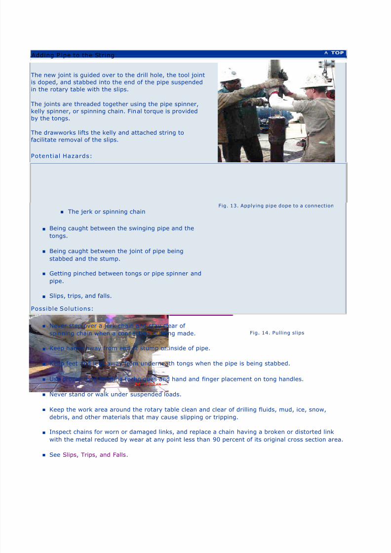
The new joint is guided over to the drill hole, the tool joint
is doped, and stabbed into the end of the pipe suspended
in the rotary table with the slips.
The joints are threaded together using the pipe spinner,
kelly spinner, or spinning chain. Final torque is provided
by the tongs.
The drawworks lifts the kelly and attached string to
facilitate removal of the slips.
Potential Hazards:
n Being struck by:
n Swinging kelly and pipe
n Tongs if the stabber misses the stump
n The jerk or spinning chain
n Being caught between the swinging pipe and the
tongs.
n Being caught between the joint of pipe being
stabbed and the stump.
n Getting pinched between tongs or pipe spinner and
pipe.
n Slips, trips, and falls.
Possible Solutions:
n Never step over a jerk chain and stay clear of
spinning chain when a connection is being made.
n Keep hands away from end of stump or inside of pipe.
n Keep feet and legs away from underneath tongs when the pipe is being stabbed.
n Use proper tong latching techniques and hand and finger placement on tong handles.
n Never stand or walk under suspended loads.
n Keep the work area around the rotary table clean and clear of drilling fluids, mud, ice, snow,
debris, and other materials that may cause slipping or tripping.
n Inspect chains for worn or damaged links, and replace a chain having a broken or distorted link
with the metal reduced by wear at any point less than 90 percent of its original cross section area.
n See Slips, Trips, and Falls.
Fig. 13. Applying pipe dope to a connection
Fig. 14. Pulling slips
Adding P ipe to the String

8/4/2019 Oil and Gas Drilling Task
http://slidepdf.com/reader/full/oil-and-gas-drilling-task 18/51

8/4/2019 Oil and Gas Drilling Task
http://slidepdf.com/reader/full/oil-and-gas-drilling-task 19/51
U.S. Department of LaborOccupational Safety & Health Administration
w w w .o s h a . g o v [skip navigational links] Search Advanced Search | A-Z In dex
Drilling >> Drilling Ahead >> Drilling Fluid
n Drilling Fluid Functions
n Drilling Fluid Types
n Drilling Fluid Additives
Additional References
Drilling Fluid Functions
Drilling fluid is an important component in the
drilling process. A fluid is required in the
wellbore to:
n Cool and lubricate the drill bit,
n Remove the rock fragments, or drill
cuttings, from the drilling area and
transport them to the surface,
n Counterbalance formation pressure toprevent formation fluids (such as oil, gas,
and water) from entering the well
prematurely (which can lead to a blowout), and
n Prevent the open (uncased) wellbore from caving in.
Fig. 1 Drilling fluid (Mud)
Drilling Fluid Types
There are several types of drilling fluids used depending on the drilling conditions encountered:
n Water-based muds are used most frequently. The base may be either:
n fresh water, or
n salt water.
n Oil-based muds.
n Synthetic materials. The oil and gas extraction industry has developed many new oleaginous
(oil-like) base materials from which to formulate high-performance drilling fluids.
A general class of these fluids is called synthetic materials, such as
Home General Safety Site Preparation Drilling Well Completion Servicing Plug and Abandon the Well

8/4/2019 Oil and Gas Drilling Task
http://slidepdf.com/reader/full/oil-and-gas-drilling-task 20/51
n The vegetable esters,
n Poly alpha olefins,
n Internal olefins,
n Linear alpha olefins,
n Synthetic paraffins,
n Ethers, and
n Linear alkylbenzenes, among others.
n Air and foam fluids may be used in drilling wells.
n These fluids are less dense than drilling muds.
Drilling Fluid Additives
Drilling muds typically have several additives. (Airand foam fluids typically do not contain many
additives because the additives are either liquid or
solid, and will not mix with air and foam drilling
fluids.) The following is a list of the more significant
additives:
n Weighting materials, primarily barite (barium
sulfate), may be used to increase the density
of the mud in order to equilibrate the
pressure between the wellbore and formation
when drilling through particularly pressurized
zones. Hematite (Fe2O
3) sometimes is used
as a weighting agent in oil-based muds(Souders, 1998).
n Corrosion inhibitors such as iron oxide, aluminum bisulfate, zinc carbonate, and zinc
chromate protect pipes and other metallic components from acidic compounds encountered in
the formation.
n Dispersants, including iron lignosulfonates, break up solid clusters into small particles so they
can be carried by the fluid.
n Flocculants, primarily acrylic polymers, cause suspended particles to group together so they
can be removed from the fluid at the surface.
n Surfactants, like fatty acids and soaps, defoam and emulsify the mud.
n Biocides, typically organic amines, chlorophenols, or formaldehydes, kill bacteria and help
reduce the souring of drilling mud.
n Fluid loss reducers include starch and organic polymers and limit the loss of drill ing mud to
under-pressurized or high-permeability formations.
Fig. 2 Additive mixing hopper
eTool Home | Site Preparation | Drilling | Well Completion | Servicing | Plug & Abandon Well
General Safety | Additional References | Viewing/Printing Instructions | Credits | JSA
Safety and Health Topic | Site Map | Illustrated Glossary | Glossary of Terms

8/4/2019 Oil and Gas Drilling Task
http://slidepdf.com/reader/full/oil-and-gas-drilling-task 21/51
U.S. Department of LaborOccupational Safety & Health Administration
w w w .o s h a . g o v [skip navigational links] Search Advanced Search | A-Z In dex
Drilling >> Drilling Ahead >> MSDS
This Material Safety Data Sheet (MSDS) contains information on the use and procedures for handling
Caustic Soda. There are data sheets on all the hazardous chemicals used in the drilling industry. Data
sheets must be supplied by the manufacturer and/or supplier each time the chemical is introduced into
the workplace. See Hazard Communication: Toxic and Hazardous Substances [1910.1200]
MATERIAL SAFETY DATA SHEET
CAUSTIC SODA (NaOH)
1. CHEMICAL PRODUCT AND COMPANY IDENTIFICATION
TRADE NAME: CAUSTIC SODA (NaOH)
UN/ NA (PIN) No.: 1823
CHEMICAL CLASS: Bases, alkalies (inorganic).
APPLICATIONS: Oil well drilling fluid additive. pH modifier.
EMERGENCY TELEPHONE: 281-561-1600
SUPPLIER: Supplied by a Business Unit of M-I L.L.C.
P.O. Box 42842, Houston, Texas 77242-2842See cover sheet for local supplier.
TELEPHONE: 281-561-1509
FAX: 281-561-7240
CONTACT P ERSON: Sam Hoskin
2. COMPOSITION, INFORMA TION ON INGREDIENTS
INGREDIENT NAME: CAS No.: CONTENTS : EPA RQ: TPQ:
Sodium hydroxide 1310-73-2 100 % 1 000 lbs
3. HAZARDS IDENTI FICATI ON
EMERGENCY OVERVIEW:
DANGER! CAUSES EYE AND SKIN BURNS. Do not get in eyes or on skin or
clothing. Avoid breathing airborne product. Keep container closed. Use only with
adequate ventilation. Wash thoroughly after handling. Avoid contact with water
or moisture, which may generate sufficient heat to ignite combustible materials.
This product is a white pellet or flake material. Slippery when wet.
ACUTE EFFECTS:
Home General Safety Site Preparation Drilling Well Completion Servicing Plug and Abandon the Well

8/4/2019 Oil and Gas Drilling Task
http://slidepdf.com/reader/full/oil-and-gas-drilling-task 22/51
HEALTH HA ZARDS, GENERAL:
Contact with this product is severely irritating to the eyes, skin, and respiratory
tract and may cause severe eye injury.
INHALATION: Severely irritating to the respiratory tract if inhaled.
INGESTION: May cause burns in mucous membranes, throat,
esophagus, and stomach.
SKIN: Corrosive to skin.
EYES: Corrosive to eyes.
CHRONIC EFFECTS:
CARCINOGENICITY:
IARC: Not listed. OSHA: Not regulated. NTP: Not listed.
10296 - CAUSTIC SODA (NaOH)
ROUTE OF ENTRY:
Inhalation. Skin and/or eye contact.
TARGET ORGANS:
Respiratory system, lungs. Skin. Eyes.
4. FIR ST AID MEASURES
GENERAL: Persons seeking medical attention should carry a copy of this MSDS with them.
INHALATION: Move the exposed person to fresh air at once. Perform artificial respiration if
breathing has stopped. Get medical attention.
INGESTION: Drink a couple of glasses water or milk. Do NOT induce vomiting unless
directed to do so by a physician. Never give anything by mouth to an unconscious person.
Get medical attention.
SKIN: Wash skin thoroughly with soap and water. Remove contaminated clothing. Getmedical attention if any discomfort continues.
EYES: Promptly wash eyes with lots of water while lifting the eye lids. Continue to rinse for
at least 15 minutes. Get medical attention if any discomfort continues.
5. FIRE FIGHTING MEASURES
AUTO IGNITI ON TEMP. (°F): N/D
FLAMMABILITY LIMI T - LOWER(%): N/D
FLAMMABILITY LIMIT - UPPER(%): N/D
EXTINGUISHING MEDIA:
Carbon dioxide (CO2). Dry chemicals. Foam.
SPECIAL FIRE FI GHTING PROCEDURES:
No specific fire fighting procedure given.
UNUSUAL FIRE & EXPLOSION HAZARDS:
Upon contact with certain metals and water or moist air, hydrogen gas is
generated, forming explosive mixtures with air.
HAZARDOUS COMBUSTION P RODUCTS:

8/4/2019 Oil and Gas Drilling Task
http://slidepdf.com/reader/full/oil-and-gas-drilling-task 23/51
Irritating gases/vapors/fumes.
6. ACCIDENTAL RELEASE MEASURES
PERSONAL PRECAUTIONS:
Wear proper personal protective equipment (see MSDS Section 8).
SPILL CLEAN-UP P ROCEDURES:
Avoid generating and spreading of dust. Shovel into dry containers. Cover and
move the containers. Flush the area with water. Do not contaminate drainage or
waterways. Repackage or recycle if possible.
7. HANDLIN G AND STORAGE
HANDLING PRECAUTIONS:
Avoid handling that causes dust to generate. Wear full protective clothing for
prolonged exposure and/or high concentrations. Make eye wash and emergency
shower available at the work place. Wash hands often and change clothing when
needed. Provide good ventilation. Provide mechanical ventilation or local exhaustventilation.
STORAGE PRECAUTIONS:
Store at moderate temperatures in dry, well ventilated area. Keep in original
container.
8. EXPOSURE CONTROLS, PERSONAL PROTECTION
*C = Ceiling Limit
PROTECTIVE EQUIPMENT:
ENGINEERING CONTROLS: Use appropriate engineering controls such as exhaust
ventilation and process enclosure to reduce air contamination and keep worker exposure
below the applicable limits.
VENTILATION: Supply natural or mechanical ventilation adequate to exhaust airborne
product and keep exposures below the applicable limits.
RESPIRATORS: Use at least a NIOSH-approved N95 half-mask disposable or reuseable
particulate respirator. In work environments containing oil mist/aerosol, use at least a
NIOSH-approved P95 half-mask disposable or reuseable particulate respirator.
PROTECTIVE GLOVES: Use gauntlet type rubber gloves.
EYE PROTECTION: Use tight-fitting goggles if dust is generated. Wear splash-proof eye
goggles to prevent any possibility of eye contact.
PROTECTIVE CLOTHING: Wear appropriate clothing to prevent any possibility of skin
contact. Provide eyewash station and safety shower.
HYGIENIC W ORK PR ACTICES: Wash promptly with soap and water if skin becomes
contaminated. Change work clothing daily if there is any possibility of contamination.
9. PHY SICAL AND CHEMICAL PROPERTI ES
OSHA PEL: ACGIH TLV: OTHER:
INGREDIENT
NAME:CAS No.: TWA: STEL:
TWA:
STEL:TWA: STEL: UNITS:
Sodium
hydroxide1310-73-2 2 2 C* mg/m3

8/4/2019 Oil and Gas Drilling Task
http://slidepdf.com/reader/full/oil-and-gas-drilling-task 24/51
APP EARANCE/ PHY SICAL STATE: Pellets or flakes.
COLOR: White.
ODOR: Odorless or no characteristic odor.
SOLUBILITY DESCRIPTION: Soluble in water.
BOILING POINT ( °F, interval): 2530 PRESSURE: 760mmHg
MELT./ FREEZ. POIN T (°F, interval): 604
DENSITY/ SPECIFIC GRAVITY (g/ ml): 2.13 TEMPERATURE (°F): 68
BULK DENSITY : 133 lb/cu. ft.; 2131 kg/m3
VAPOR DENSITY (air=1): N/A
VAPOR PRESSURE: 42 mmHg TEMPERATURE (°F): 1832
pH-VALUE, DILUTED SOLUTION: 13 CONCENTRATION (%,M): 1%
10. STABILITY AND REACTIVITY
STABILITY: Normally stable.
CONDITI ONS TO AVOID: Reacts strongly with water. Avoid contact with acids.
HAZARDOUS P OLYMERIZATION: Will not polymerize.
POLYMERI ZATION DESCRIP TION: Not relevant.
MATERIALS TO AVOID: Organochlorine solvents, nitro and nitroso compounds, organic
peroxides; aluminum, zinc, tin and their alloys.
HAZARDOUS DECOMPOSITION P RODUCTS: No specific hazardous decomposition
products noted.
11. TOXICOLOGICAL INFORMATION
Component: Sodium hydroxide
TOXICOLOGICAL DATA:
24 hours. Eye. Rabbit. 1 mg Severe Irritation Corrosive effects.
24 hours. Skin. Rabbit. 500 mg Severe Irritation Corrosive effects.
LDLo. Oral. Rabbit. 500 mg/kg Acute toxicity.
TOXI C DOSE - LD 50: 1350 mg/kg (skn-rbt)
12. ECOLOGICAL INFORMATI ON
LC 50, 96 HRS, FISH, mg/ l: 125 (Mosquitofish)
EC 50, 48 HRS, DAPHNI A, mg/ l: 100
ACUTE AQUATIC TOXICITY:
This product passes the mysid shrimp toxicity test required by the U.S.
Environmental Protection Agency (EPA) Region VI (Gulf of Mexico) NPDES
Permit, which regulates offshore discharge of drilling fluids, when tested in a
standard drilling fluid. Contact M-I's Environmental Affairs Department for more
information.
This product is approved for use under the U.S. Environmental Protection Agency(EPA) Region IX (California) General NPDES Permit which regulates offshore
discharges of drilling fluids. Contact M-I's Environmental Affairs Department for
more information.
13. DISPOSAL CONSIDERATI ONS
WASTE MANAGEMENT:
This product, should it become a waste, is hazardous by U.S. RCRA criteria.
THIS CONTAINER MAY BE HAZARDOUS WHEN EMPTY. Empty containers retain
residues. All labeled precautions must be observed.

8/4/2019 Oil and Gas Drilling Task
http://slidepdf.com/reader/full/oil-and-gas-drilling-task 25/51
DISPOSAL M ETHODS:
Recover and reclaim or recycle, if practical. Should this product become a waste,
dispose of in a permitted industrial landfill. Ensure that containers are empty by
RCRA criteria before disposal in a permitted industrial landfill.
14. TRANSPORT INFORMATI ON
LABEL FOR CONVEYANCE:PROPER SHIPPI NG DESCRIPTION II: Sodium hydroxide, solid, 8, UN1823, PG II
GENERAL: RQ = 1000
EMERGENCY RESPONSE GUIDE No.: 154
U.S. DOT:
UN/ NA No.: 1823
U.S. DOT HAZARD LABEL : CORROSIVE (Black/white diam.) DOT17
U.S. DOT CLASS: Class 8 - Corrosive Material
U.S. DOT PACKI NG GROUP: II
U.S. DOT PACKAGING INSTRUCTIONS: 49 CFR 173.154; 173.212; 240
CANADIAN TRANSPORT:
TDGR CLASS: Class 8 - Corrosives
TDGR LABEL: Corrosive
SEA TRANSPORT:
UN N o. SEA: 1823
IMDG CLASS: Class 8 - Corrosives
IMDG PAGE No.: 8225-1
IMDG PACK GR.: II
EmS No.: 8-06
MFAG TABLE No.: 705
AIR TRANSPORT:
UN No., AIR: 1823
ICAO CLASS: Class 8 - Corrosives
AIR PACK GR.: II
15. REGULATORY INFORM ATION
US FEDERAL REGULATIONS:
WASTE CLASSIFICATION: A hazardous waste by U.S. RCRA criteria
REGULATORY STATUS: This product or its components, if a mixture, is subject to following
regulations (Not meant to be all-inclusive, selected regulations represented):
SECTION 313: This product does not contain toxic chemical subject to the reporting
requirements of Section 313 of Title III of the Superfund Amendment and Reauthorization
Act of 1986 and 40 CFR Part 372.
REGULATORY
STATUS OF
INGREDIENTS:
CAS No: TSCA: CERCLA: SARA 302: SARA 313:DSL
(CAN):
NAME: Sodium hydroxide
1310-73-2 Yes Yes No No Yes
8/4/2019 Oil and Gas Drilling Task
http://slidepdf.com/reader/full/oil-and-gas-drilling-task 26/51
SARA 311 Categories:
1: Immediate (Acute) Health Effects
5. Reactivity Hazard
The components of this product are listed on or are exempt from the following international
chemical registries:
TSCA (U.S.)
DSL (Canada)
STATE REGULATIONS:
STATE REGULATORY STATUS: This product or its components, if a mixture, is subject to following
regulations (Not meant to be all-inclusive, selected regulations represented):
Illinois Right-to-Know
New Jersey Right-to-Know
Pennsylvania Right-to-Know
PROPOSITION 65: This product does not contain chemicals considered by the State of California's Safe Drinking Water and Toxic Enforcement Act of 1986 as causing cancer or
reproductive toxicity, and for which warnings are now required.
CANADIAN REGULATIONS:
LABELS FOR SUPPLY :
REGULATORY STATUS:
This Material Safety Data Sheet has been prepared in compilance with the Controlled Product
Regulations.
Canadian WHMIS Classification: E - Corrosive Material D2B - Other Toxic Effects: Toxic
Material
16. OTHER INFORMATION
NPCA HMI S HAZARD INDEX: 3 Serious Hazard
FLAMMABILITY: 0 Minimal Hazard
REACTIVITY: 1 Slight Hazard
NPCA HMIS PERS. PROTECT. IN DEX: X Ask your supervisor for guidance
USER NOTES: N/A = Not applicable N/D = Not determined
INFORM ATION SOURCES:
OSHA Permissible Exposure Limits, 29 CFR 1910, Subpart Z, Section 1910.1000,
Air Contaminants.
ACGIH Threshold Limit Values and Biological Exposure Indices for Chemical
Substances and Physical Agents (latest edition). Sax's Dangerous Properties of
Industrial Materials, 9th ed., Lewis, R.J. Sr., (ed.), VNR, New York, New York,
(1997).
Product information provided by the commercial vendor(s).
PREPAR ED BY: Sam Hoskin

8/4/2019 Oil and Gas Drilling Task
http://slidepdf.com/reader/full/oil-and-gas-drilling-task 27/51
REVISION N o./ Repl. MSDS of: 1 / June 3, 1996
MSDS STATUS: Approved.
DATE: June 9, 1998
DISCLAIMER:
MSDS furnished independent of product sale. While every effort has been made to accurately describethis product, some of the data are obtained from sources beyond our direct supervision. We cannot make
any assertions as to its reliability or completeness; therefore, user may rely on it only at user's risk. We
have made no effort to censor or conceal deleterious aspects of this product. Since we cannot anticipate
or control the conditions under which this information and product may be used, we make no guarantee
that the precautions we have suggested will be adequate for all individuals and/or situations. It is the
obligation of each user of this product to comply with the requirements of all applicable laws regarding
use and disposal of this product. Additional information will be furnished upon request to assist the user;
however, no warranty, either expressed or implied, nor liability of any nature with respect to this product
or to the data herein is made or incurred hereunder.
eTool Home | Site Preparation | Drilling | Well Completion | Servicing | Plug & Abandon Well
General Safety | Additional References | Viewing/Printing Instructions | Credits | JSA Safety and Health Topic | Site Map | Illustrated Glossary | Glossary of Terms
Back to Topwww.osha.gov www.dol.gov
Contact Us | Freedom of Information Act | Information Quality | Customer Survey
Privacy and Security Statement | Disclaimers
Occupational Safety & Health Administration
00 Constitution Avenue, NW
Washington, DC 20210

8/4/2019 Oil and Gas Drilling Task
http://slidepdf.com/reader/full/oil-and-gas-drilling-task 28/51
U.S. Department of LaborOccupational Safety & Health Administration
w w w .o s h a . g o v [skip navigational links] Search Advanced Search | A-Z In dex
Drilling >> Tripping Out/ In
Tripping refers to the process of removing and/or
replacing pipe from the well when it is necessary to
change the bit or other piece of the drill string, or when
preparing to run certain tests in the well bore.
The activities that comprise tripping out are listedbelow. Tripping in essentially comprises the same steps
in reverse order.
Additional Information:
n IADC /PETEX Rotary Drilling Series
n IADC APRG
n API RP 54
Fig. 1. Setting back a stand of drill pipe
Tripping Out Tripping In
n Setting Slips
n Breaking Out and Setting Back the Kelly
n Attaching Elevators to Elevator Links
n Latching Elevators to Pipe
n Working on the Monkeyboard
n Breaking Out Pipe
n Maneuvering Pipe to Racking Area
n Elevators raised
n Latching Elevators to Top of Stand
n Moving pipe to rotary
n Pipe is made up
n Slips are pulled
n Slips are set
n Elevators are unlatched
n Process repeated for all stands
n Pickup kelly and attach to drill string
n Break circulation, and
n Resume drilling
Tripping Ou t - Setting Slips
The floor crew sets slips around the drill stem.
Potential Hazards:
n Getting fingers or other body parts pinched between
Home General Safety Site Preparation Drilling Well Completion Servicing Plug and Abandon the Well

8/4/2019 Oil and Gas Drilling Task
http://slidepdf.com/reader/full/oil-and-gas-drilling-task 29/51
slips or slip handles and rotary table.
n Receiving muscle strain from improper lifting
technique.
Possible Solutions:
n Use proper hand placement when setting slips.
n Use proper stance and slip lifting techniques. Slipshave three handles and should be lifted jointly by
more than one person.
Additional Information:
n IADC /PETEX Rotary Drilling Series
n IADC APRG
n API RP 54
Fig. 2. Setting sli ps
Breaking Out and Setting Back the Kelly
Breakout the kelly and set it into the rathole.
Potential Hazards:
n Release of excess drilling mud resulting in skin contact, loss of
footing, etc.
Possible Solutions:
n Shut down the mud pumps before breaking out the kelly.
n Close the mud saver valve on the kelly (if present).
n Use a mud bucket to divert flow of excess mud.
Potential Hazards:
n Being struck by the slip handles if the rotary table is used to spin the drill string.
Possible Solutions:
n Stand clear of the rotary table when it is rotating.
n Consider other technologies (such as a pipe spinner, kelly spinner , or top drive unit) to eliminate
this hazard.
Potential Hazards:
n Being struck by the kelly if the pullback line unhooks when kelly is being pulled toward the rathole.
Possible Solutions:
n Implement an effective pullback line attachment procedure.
n Ensure workers stand in a safe location away from the pullback line and rathole during this pullback
Fig. 3. Kelly set into ratho le
operation.

8/4/2019 Oil and Gas Drilling Task
http://slidepdf.com/reader/full/oil-and-gas-drilling-task 30/51
Attaching Elevators to the Elevator Links
The crew attaches elevators to the elevator links.
Potential Hazards:
n Being pinched by the elevator links while attaching
elevators (or attaching elevator links to the hook).
n Being struck by the elevators.
n Receiving strains and sprains.
Possible Solutions:
n Use proper hand placement when attaching elevator links.
n
Ensure workers stand away from swing-path of the elevators and elevator links.
n Use lifting equipment and limit manual positioning of elevators.
n Use proper mounting procedures.
Fig. 4. Red elevator links
Latching Elevators to Pipe
The floor crew latches the elevators onto the pipe.
Potential Hazards:
n Getting hands or fingers pinched in elevators.
n Being struck by elevators not securely latched.
n Getting hands or fingers caught between
elevators and stump.
Possible Solutions:
n Ensure workers are instructed in proper latching procedure, including the use of handles on
elevators as they are descending into place over the stump or tool joint.
n Inspect and maintain elevators.
Additional Information:
n API RP 8B Inspection, Maintenance, Repair, and Remanufacture of Hoisting Equipment
Fig. 5. Elevators latched onto the pipe

8/4/2019 Oil and Gas Drilling Task
http://slidepdf.com/reader/full/oil-and-gas-drilling-task 31/51
The elevators are then lowered and attached to the
next stand of pipe.
Potential Hazards:
n Falling while climbing up or down the ladder.
n Falling from monkeyboard or fingerboard.
n Slips, trips, and falls.
n Falling during an emergency descent.
Possible Solutions:
n Use climb assist device.
n Wear appropriate fall protection including afull body harness. For Fall Protection
guidance, consult:
n [1910.23(c)(1)], Fall Protection when
working from platforms.
n [1910.66 App (C) ], Fall Protection
guidelines.
n [1910 Subpart D ], Walking-Working
Surfaces.
n Wear the proper Personal Protective
Equipment such as:
n Hard hat
n Work gloves
n Safety-toed footwear
n Practice 100% tie-off while working in the
derrick.
n Use slip-resistant coatings or materials on
working surfaces.
n Train personnel in use of emergency escape
device.
Potential Hazards:
n Being caught between pipe and other objects
n Receiving strains and sprains.
Possible Solutions:
n Practice proper hand placement and use of
pullback (tail) ropes.
Potential Hazards:
Fig. 6. Climbing Assist Device and P PE
Fig. 7. Derrickman on monkeyboard
Fig. 8. Handling pipe from monkeyboard
Working on the Monkeyboard
The derrickman climbs up the derrick to the
monkeyboard . From here he unlatches the elevators
and guides the stands of pipe into the fingerboard.

8/4/2019 Oil and Gas Drilling Task
http://slidepdf.com/reader/full/oil-and-gas-drilling-task 32/51
n Being struck by dropped objects.
Possible Solutions:
n Implement a dropped objects program, such as tie-off for all tools.
n Use extra caution while personnel are working overhead.
n Do not carry tools while climbing the derrick ladder. Raise tools with a line to any worker above the
derrick floor.
Additional Information:
n Fall Protection
n ANSI Z359.1
n Personal Fall Arrest Systems (Please recognize that there is a weight limit, including
equipment)
n IADC Fall Protection Guidance
Breaking Out Pipe
The crew uses the tongs and cathead to breakout the
pipe. The rotary table may be used to spin out the pipe
after breaking the connection.
Potential Hazards:
n Being struck by swinging tongs if they break free
from the pipe.
n Being struck by the slip handles if the rotary
table is used to spin the drill string.
n Being struck by reverse backlash of tongs(backbiting) during breakout operations.
n Being struck by the tongs if a snub line breaks
or the tongs come unlatched.
Possible Solutions:
n Implement an effective breakout pipe
procedure:
n Personnel other than tong operators stand
outside the tong swing radius when
breaking pipe.
n No one should stand in the red zone. (see
Diagram 1)
n Use proper tong latching techniques and
use proper hand and finger placement on
tong handles.
n Stand clear of the rotary table when it is rotating.
Fig. 9. Using the tongs to breakout the pipe
Fig. 10. Tong sw ing radius
n Use special operational procedures when making high torque connections.
n Inspect tong dies and snub lines each tour.
n Maintain good communication between floor hands and driller.

8/4/2019 Oil and Gas Drilling Task
http://slidepdf.com/reader/full/oil-and-gas-drilling-task 33/51
Maneuvering Pipe to Racking Area
The stand is raised and maneuvered to the pipe
racking area.
Potential Hazards:
n Getting hands and fingers pinched between
stands of pipe.
n Getting feet or toes crushed or amputated under
a stand of pipe.
n Slips, trips, and falls.
n Receiving strains and sprains.
Possible Solutions:
n Keep hands and fingers from between pipe
stands.
n Position feet away from the bottom of the pipe stands.
n See General Safety & Health.
Fig. 11. Crew maneuvers stand into rackin g area
Tripping in - Latching Elevators to Top of Stand
The derrickman latches the elevators onto the pipe
from the monkeyboard.
Potential Hazards:
n Getting hands or fingers pinched in elevators.
n Being struck by elevators not securely latched.
n Getting hands or fingers caught between
elevators and stump.
Possible Solutions:
n Ensure workers are instructed in proper latching procedure.
n Inspect and maintain elevators.
Fig. 12. Derrickman latchin g elevators onto the pipe
eTool Home | Site Preparation | Drilling | Well Completion | Servicing | Plug & Abandon Well General Safety | Additional References | Viewing/Printing Instructions | Credits | JSA
Safety and Health Topic | Site Map | Illustrated Glossary | Glossary of Terms
Back to Top www.osha.gov www.dol.gov
Contact Us | Freedom of Information Act | Customer Survey
Privacy and Security Statement | Disclaimers
ashington, DC 20210
ccupational Safety & Health Administration
00 Constitution Avenue, NW

8/4/2019 Oil and Gas Drilling Task
http://slidepdf.com/reader/full/oil-and-gas-drilling-task 34/51
U.S. Department of LaborOccupational Safety & Health Administration
w w w .o s h a . g o v [skip navigational links] Search Advanced Search | A-Z In dex
Drilling >> Casing Operations
Casing is pipe usually larger in diameter and longer
than drill pipe and is used to line the hole. Casing
operations occur periodically throughout the drilling
process starting with the surface casing,
intermediate casing, and ending with production
string which takes place during well completion.
The activities involved in casing operations can vary
according to the type of casing being installed, but
generally fall into these steps:
n Installing Casing Tools
n Running Casing into the Hole
n Installing Casing Accessories
n Circulating and Cementing
Fig. 1. Installing casing
Installing Casing Tools
Specialized casing handling tools are necessary
to run casing.
Note: The special service supervisor should hold
a pre-job meeting with the special service crew
and other involved personnel to review
responsibilities and to coordinate the operations
to be performed.
Potential Hazards:
n Being struck by or caught between
tubulars and other objects during
movement (such as being struck by
tubulars being tailed into the rig floor).
n Experiencing strains and sprains from
maneuvering tools.
n Falling from work platform and/or stabbing
Fig. 2. Special casing elevators
Home General Safety Site Preparation Drilling Well Completion Servicing Plug and Abandon the Well

8/4/2019 Oil and Gas Drilling Task
http://slidepdf.com/reader/full/oil-and-gas-drilling-task 35/51
board.
Possible Solutions:
n Stand clear of suspended, hoisted or
moving loads. Be aware of tubulars or
equipment being lifted through the V-door.
n Use proper hand and foot placement to
avoid pinch points, including use of taglines.
n Use rig floor winch or other powered
equipment to handle heavy casing tools.
n Use fall protection while installing equipment in the derrick.
n See Slips, Trips, and Falls.
Fig. 3. Derrickman latching elevators
Running Casing into the Hole
Casing is run into the hole to a pre-determined
depth.
Note: The special service supervisor should hold
a pre-job meeting with the special service crew
and other involved personnel to review
responsibilities and to coordinate the operations
to be performed.
Potential Hazards:
n Hazards are similar to those for drilling
ahead or tripping.
n Getting caught between, struck by, or
pinched by the power tongs, casing or
other equipment.
n Being struck by or caught between
tubulars and other objects during
movement (for example, struck by tubulars
being tailed into the rig floor).
n Falling from the stabbing board or work
platform.
n Getting struck by dropped objects.
Possible Solutions:
n Include the casing crew and the drilling
crew when conducting a JSA and pre-job
safety meeting to coordinate the activities of casing operations.
n Stand clear of suspended, hoisted, or moving loads. Be aware of tubulars or equipment being
lifted through the V-door.
Fig. 4. Lifting cas ing onto rig floor
Fig. 5. Casing stabber

8/4/2019 Oil and Gas Drilling Task
http://slidepdf.com/reader/full/oil-and-gas-drilling-task 36/51
n Emphasize all normal worker safety procedures, such as fall protection, PPE, placement of
hands and feet, and teamwork and communication between workers.
n Implement full fall protection program for the casing stabber.
n Identify clearance between the stabbing board and casing elevators.
n Secure all items used by the casing stabber overhead with a safety line.
Installing Casing Accessories
As casing is being run, accessories such as
centralizers, scratchers, guide shoe, and a float
collar are installed and used as needed.
Note: The special service supervisor should hold
a pre-job meeting with the special service crew
and other involved personnel to review
responsibilities and to coordinate the operations
to be performed.
Potential Hazards:
n Dropping guide shoe or float collar onto
legs or foot.
n Getting fingers pinched between tools andcasing tongs when manually moving guide
shoe or float collar.
n Back strain
n Exposure to hazardous materials,
especially thread lock compounds.
Possible Solutions:
n Use winch, air hoist, or other powered
equipment to handle guide shoe, float
collar, or other heavy casing equipment.
n Use appropriate PPE as required by the MSDS.
Fig. 6. Casing guid e shoe
Fig. 7. Installing casing centralizer

8/4/2019 Oil and Gas Drilling Task
http://slidepdf.com/reader/full/oil-and-gas-drilling-task 37/51
Potential Hazards:
n Being struck by high-pressure lines failing if
not secured properly.
n Having a high pressure connection failurecaused by mismatched or excessively worn
hammer unions.
Possible Solutions:
n Hobble high-pressure lines properly.
n Use proper equipment inspection techniques to
include hammer unions (Note: This is a particular problem with 602 and 1502, as they will
couple but will not hold beyond the lower pressure rating number).
n See IADC Alert 98 -01, High Pressure Lines And Hammer Unions.
n See IADC Alert 99-33, More On Mismatched Hammer Unions.
n See IADC Alert 00-15, Additional Serious Incidents With Mismatched Hammer Unions.
n See IADC Meeting Minutes 02 November1999, Mismatched Hammer Unions, Industry
Fig. 8. High pressur e lines
eTool Home | Site Preparation | Drilling | Well Completion | Servicing | Plug & Abandon Well
General Safety | Additional References | Viewing/Printing Instructions | Credits | JSA
Safety and Health Topic | Site Map | Illustrated Glossary | Glossary of Terms
Back to Top www.osha.gov www.dol.gov
Contact Us | Freedom of Information Act | Customer Survey
Privacy and Security Statement | Disclaimers
ccupational Safety & Health Administration
0 Constitution Avenue, NW
ashington, DC 20210
Circulating and Cementing
After the casing is landed, drilling fluid is circulated
through the casing and annulus to remove any
residual gases and to condition the mud.
After circulating and conditioning the mud, the
casing is cemented. During this process the casing is
reciprocated or rotated to allow the scratchers to
work to remove excess wall cake to give the cement
a better bond.
Usually another special servicing company is hired to
conduct cementing operations.
wide meeting.

8/4/2019 Oil and Gas Drilling Task
http://slidepdf.com/reader/full/oil-and-gas-drilling-task 38/51
U.S. Department of LaborOccupational Safety & Health Administration
w w w .o s h a . g o v [skip navigational links] Search Advanced Search | A-Z In dex
Drilling >> Maintenance Activities
Proper maintenance prevents premature equipment
failure, which may cause injuries or fatalities.
Drilling equipment is subjected to stress and
vibration during operations. Maintenance is a
necessary and ongoing activity on the drilling site.
Maintenance activities include maintaining the:
n Rig Floor
n Drilling Line Maintenance
n Wire rope maintenance
n Mud Circulating System
n Generator, Electric Motors and Electrical
Systems
n Engines
n Derrick Equipment Maintenance
Fig. 1. Welding
Rig Floor
Fig. 2. Engines, compound, and drawworks
Maintenance activities include inspecting,
adjusting, and servicing on equipment such as
drawworks, rotary, catheads, tongs, air hoists,
and wire rope.
Potential Hazards:
n Slips, trips, and falls.
Possible Solutions:
n Wear personal protective equipment(such as hard hats, work gloves, safety
shoes, and eye protection).
n Be aware of the slipping and falling
hazards when performing maintenance
on the drilling floor.
n Keep all work areas clean and clear of
oil, tools, and debris.
n Use non-skid surfaces where appropriate.
Home General Safety Site Preparation Drilling Well Completion Servicing Plug and Abandon the Well

8/4/2019 Oil and Gas Drilling Task
http://slidepdf.com/reader/full/oil-and-gas-drilling-task 39/51
Potential Hazards:
n Being caught in chains or other moving equipment.
n Getting fingers and hands pinched in machine guards or covers.
n Receiving sprains and strains.
Possible Solutions:
n Wear personal protective equipment (such as hard hats, work gloves, safety shoes, and
eye protection).
n Use proper lockout/tagout procedures. [ 1910.147]
n Seek assistance when moving awkward and heavy guards and covers.
n Maintain all machinery free of leaks by regular preventive maintenance and repairing
when necessary.
Drilling Line Maintenance
The drilling line is the steel wire rope reeved through the
crown block and traveling block. It must be inspected,
slipped and cut regularly.
Potential Hazards:
n Receiving injuries to face and eyes from flying chips
of metal when slipping and cutting the line.
n Being caught in moving equipment.
n Slips, trips, and falls.
n Being struck by drilling line.
Possible Solutions:
n Use proper lockout/tagout procedures. [ 1910.147]
n Wear proper personnel protective equipment when cutting line.
n Attach a red flag or other warning device to the drawworks clutch lever as a reminder to
the driller whenever the crown safety device is moved or deactivated to allow the
traveling block to be raised above the the preset stopping point.
n Secure drilling line ends prior to cutting.
Fig. 3. Drilling line
8/4/2019 Oil and Gas Drilling Task
http://slidepdf.com/reader/full/oil-and-gas-drilling-task 40/51
Potential Hazards:
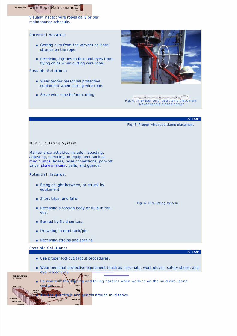
n Getting cuts from the wickers or loose
strands on the rope.
n Receiving injuries to face and eyes fromflying chips when cutting wire rope.
Possible Solutions:
n Wear proper personnel protective
equipment when cutting wire rope.
n Seize wire rope before cutting.
Fig. 4. Improper wire rope clamp placement"Never saddle a dead horse"
Fig. 5. Proper wire rope clamp placement
Mud Circulating System
Maintenance activities include inspecting,
adjusting, servicing on equipment such as
mud pumps, hoses, hose connections, pop-off
valve, shale shakers , belts, and guards.
Potential Hazards:
n Being caught between, or struck by
equipment.
n Slips, trips, and falls.
n Receiving a foreign body or fluid in the
eye.
n Burned by fluid contact.
n Drowning in mud tank/pit.
n Receiving strains and sprains.
Possible Solutions:
n Use proper lockout/tagout procedures.
n Wear personal protective equipment (such as hard hats, work gloves, safety shoes, and
eye protection).
n Be aware of the slipping and falling hazards when working on the mud circulating
system.
n Provide guardrails and guards around mud tanks.
Fig. 6. Circulating system
Wire Rope Maintenance
Visually inspect wire ropes daily or per
maintenance schedule.

8/4/2019 Oil and Gas Drilling Task
http://slidepdf.com/reader/full/oil-and-gas-drilling-task 41/51
Generator, Electric Motors and Electrical Systems
Electrical connections and power cords need to
be checked for wear for deterioration and
replaced if needed.
Electric motors need to be serviced at
recommended intervals. All guards should be
present and correctly installed and motorselectrical connections need to be kept sealed.
Potential Hazards:
n Receiving flash burns or shocks when
servicing motors, generators, and
breaker panels.
Possible Solutions:
n Do not wash down generators, electric
motors and breaker panels with water
hose.
n Use proper lockout/tagout procedures.
n Wear appropriate personal protective
equipment.
n Avoid wearing jewelry.
n Do not stand directly in front of breakers when operating.
n Use dielectric mat in front of control panel or breaker panel.
Potential Hazards:
n Being caught in moving equipment.
Possible Solutions:
n Avoid wearing jewelry.
n Use proper lockout/tagout procedures.
n Wear appropriate personal protective equipment.
n Cover with appropriate shields or guards all exposed revolving parts such as belts,
flexible drives, generators, shafts and other moving parts to prevent contact and injury.
Additional Information:
n Proper Electrical Safety (including hot sticks) . AESC, 20 KB PDF, 4 pages.
n OSHA Safety and Health Topics:
n Electrical
n Machine Guarding
Fig. 7. Electric control panel
Fig. 8. Electric rig mo tor

8/4/2019 Oil and Gas Drilling Task
http://slidepdf.com/reader/full/oil-and-gas-drilling-task 42/51
Engines
Engines require servicing at recommended
intervals.
Potential Hazards:
n Getting burned by hot fluids or engine
parts.
Possible Solutions:
n Wear appropriate personal protective
equipment.
n Let engine cool down before working on it.
n Use proper lockout/tagout procedures.
Potential Hazards:
n Being caught in moving equipment or moving parts.
Possible Solutions:
n Wear appropriate personal protective equipment.
n Use proper lockout/tagout procedures.
n Cover all exposed revolving parts with appropriate shields and guards.
Fig. 9. Diesel rig engines
Derrick Equipment Maintenance
Maintenance activities in the derrick consists of
lubricating the swivel, traveling block, and
crown block, and replacement of swivel
packing.
Potential Hazard:
n Getting caught between equipment and
objects.
Possible Solutions:
n Use proper lockout/tagout procedures.
Potential Hazard:
n Falling from heights.
Possible Solutions:
n Use appropriate fall protection.
Potential Hazard:
Fig. 10. Sw ivel maintenance

8/4/2019 Oil and Gas Drilling Task
http://slidepdf.com/reader/full/oil-and-gas-drilling-task 43/51

8/4/2019 Oil and Gas Drilling Task
http://slidepdf.com/reader/full/oil-and-gas-drilling-task 44/51
U.S. Department of LaborOccupational Safety & Health Administration
w w w .o s h a . g o v [skip navigational links] Search Advanced Search | A-Z In dex
Drilling >> Well Control
Properly trained personnel are essential for well
control activities. Well control consists of two basic
components: an active component consisting of
drilling fluid pressure monitoring activities, and a
passive component consisting of the Blowout
Preventers (BOPs). [More... BOPs]
The first line of defense in well control is to havesufficient drilling fluid pressure in the well hole.
During drilling, underground fluids such as gas,
water, or oil under pressure (the formation
pressure) opposes the drilling fluid pressure (mud
pressure). If the formation pressure is greater than
the mud pressure, there is the possibility of a
blowout.
The activities involved in well control are:
n Blowout Prevention Program
n Monitoring and Maintaining Mud System
n Installing BOPs, Accumulator, and Choke
Manifold
n Testing BOPs Accumulators, and Choke
Manifold
n Maintaining BOPs
Fig. 1. Blowout preventer stack (BOP)
Blowou t Prevention Program
Potential Hazard:
n Receiving injuries caused by loss of well control.
Possible Solutions:
n Appropriate training for tasks performed. Example topics include the following: (per IADC
WellCAP)
n Causes of kicks, including detection
n Pressure concepts and calculations
n Well control procedures
n Gas characteristics and behavior
Home General Safety Site Preparation Drilling Well Completion Servicing Plug and Abandon the Well

8/4/2019 Oil and Gas Drilling Task
http://slidepdf.com/reader/full/oil-and-gas-drilling-task 45/51
n Fluids
n Constant bottom hole pressure well control methods
n Well control equipment
n Regulatory information
n Use of appropriate well control equipment per API RP 53
n Specification
n Installation
n Maintenance
Monitoring and Maintainin g Mud System
The mud circulatory system consists of the elements
shown in the graphic to the right.
Each part of this system must function and be in
good repair to maintain well control. [See
Maintenance Activities for more...]
If the mud level increases, it may be a sign that a
kick is in progress.
On some rigs there is a mud float level gage which
sounds an automatic alarm if the mud exceeds a
pre-specified level.
Potential Hazard:
n Loss of well control (blowout)
Possible Solutions:
n Keep the mud circulating system in good
working order.
n Check and maintain the properties of the
drilling fluid, including proper pit level
periodically.
n Properly train crew in monitoring and well
control procedures.
n Maintain a properly functioning surface control
system.
Fig. 2. The mud circulatory systemView larger image
Fig. 3. Kick animationView kick animation

8/4/2019 Oil and Gas Drilling Task
http://slidepdf.com/reader/full/oil-and-gas-drilling-task 46/51
Potential Hazards:
n Being crushed by falling equipment if hoisting slings
fail.
n Being struck by, pinched by or caught between
equipment during installation.
Possible Solutions:
n Ensure workers stand clear of equipment being
hoisted and tag lines are used where appropriate.
n Coordinate hoisting tasks with rig crew.
n Inspect the hoisting slings for wear before any
hoisting operation.
n Ensure all personnel wear proper PPE.
Additional Resources:
n The API has a recommended specification for the
installation, use, and maintenance of this equipment:
RP 53 Blowout Prevention Equipment Systems for
Drilling Operations, Current Edition.
Fig. 4. Blowout P reventer (BOP)
Fig. 5. Choke manif old
Testing BOPs, Accumulators, and Choke Manifold
The BOPs, accumulators, and choke manifold shouldbe tested and properly maintained.
Potential Hazards:
n Being hit by hoses or sprayed by hydraulic
fluid if there is a seal or hydraulic line failure
during pressure testing.
Possible Solutions:
n Ensure workers stand clear of pressurized
lines during testing procedures.Fig. 6. Choke manifold
Installing BOPs, Accumulator, and Choke Manifold
The blowout preventer (BOP), accumulator and choke
manifold are installed by the rig crew after the surface
casing is set and cemented. The accumulator and choke
manifold have been set into place during rigging up and
now need to be hooked up and tested.

8/4/2019 Oil and Gas Drilling Task
http://slidepdf.com/reader/full/oil-and-gas-drilling-task 47/51
Properly maintain the surface control system.
Potential Hazards:
n Protruding pipes and objects
n
Being struck by dropped objects.
n Slips, trips, and falls.
n Atmospheric hazards
Possible Solutions:
n Wear appropriate personal protective equipment (such as
hard hats, work gloves, safety shoes, and eye
protection).
n Implement injury awareness training (such as dropped
objects, working from heights)
n Use appropriate fall protection.
n Ensure workers are aware of the slipping and falling hazards.
n Monitor for potential hazards (H2S, methane, O
2deficiency).
Fig. 7. BOP
eTool Home | Site Preparation | Drilling | Well Completion | Servicing | Plug & Abandon Well
General Safety | Additional References | Viewing/Printing Instructions | Credits | JSA
Safety and Health Topic | Site Map | Illustrated Glossary | Glossary of Terms
Back to Topwww.osha.gov www.dol.gov
Contact Us | Freedom of Information Act | Information Quality | Customer Survey
Privacy and Security Statement | Disclaimers
ccupational Safety & Health Administration
00 Constitution Avenue, NW
Washington, DC 20210
Maintaining Surface Control System

8/4/2019 Oil and Gas Drilling Task
http://slidepdf.com/reader/full/oil-and-gas-drilling-task 48/51

8/4/2019 Oil and Gas Drilling Task
http://slidepdf.com/reader/full/oil-and-gas-drilling-task 49/51
Annular BOP
Annular BOPs are designed to form a seal in the
annular space between the drill pipe and the
wellbore and are usually mounted at the top of
the BOP stack.
Fig. 3. Annular blowout preventer
Ram Type BOP
Ram type BOPs have rubber faced steel rams
that come together with great force to seal the
wellbore. Usually two or more ram-type BOP's
are mounted in the BOP stack.
Fig. 4. Ram type blowout preventer
Choke Manifold
A choke manifold is a system of valves used to
circulate out a kick and to circulate mud in of the
proper weight. This device responds
automatically to a kick and can prevent a
blowout if properly installed and maintained.
Fig. 5. Choke manifold

8/4/2019 Oil and Gas Drilling Task
http://slidepdf.com/reader/full/oil-and-gas-drilling-task 50/51
Accumulator
The BOP control system, called an accumulator,
provides the energy to operate the blowout
preventers.
This system consists of:
n Compressed gas bottles,
n Regulator valves,
n Pumps,
n Hydraulic reservoir,
n Control manifold, and
n Control valves.
Fig. 6. Accumulator
eTool Home | Site Preparation | Drilling | Well Completion | Servicing | Plug & Abandon Well
General Safety | Additional References | Viewing/Printing Instructions | Credits | JSA
Safety and Health Topic | Site Map | Illustrated Glossary | Glossary of Terms
Back to Topwww.osha.gov www.dol.gov
Contact Us | Freedom of Information Act | Information Quality | Customer Survey
Privacy and Security Statement | Disclaimers
Occupational Safety & Health Administration
00 Constitution Avenue, NWWashington, DC 20210

8/4/2019 Oil and Gas Drilling Task
http://slidepdf.com/reader/full/oil-and-gas-drilling-task 51/51