Embed Size (px)
Citation preview

Research ArticleOil-Based Drilling Fluid Plugging Method for StrengtheningWellbore Stability of Shale Gas
Pengcheng Wu,1 Chengxu Zhong,1 Zhengtao Li,1 Zhen Zhang,1 Zhiyuan Wang ,2
and Weian Huang 2,3
1Shale Gas Research Institution of PetroChina Southwest Oil & Gas Field Company, Chengdu, 610056 Sichuan, China2School of Petroleum Engineering, China University of Petroleum (East China), Qingdao, Shandong 266580, China3Key Laboratory of Unconventional Oil and Gas Development, Ministry of Education (China University of Petroleum (East China)),Qingdao, Shandong 266580, China
Correspondence should be addressed to Weian Huang; [email protected]
Received 3 November 2020; Revised 3 January 2021; Accepted 27 January 2021; Published 17 February 2021
Academic Editor: Guanglong Sheng
Copyright © 2021 PengchengWu et al. This is an open access article distributed under the Creative Commons Attribution License,which permits unrestricted use, distribution, and reproduction in any medium, provided the original work is properly cited.
Finding out the reasons for wellbore instability in the Longmaxi Formation and Wufeng Formation and putting forward drillingfluid technical countermeasures to strengthen and stabilize the wellbore are very crucial to horizontal drilling. Based on X-raydiffraction, electron microscope scanning, linear swelling experiment, and hot-rolling dispersion experiment, thephysicochemical mechanism of wellbore instability in complex strata was revealed, and thus, the coordinated wellbore stabilitymethod can be put forward, which is “strengthening plugging of micropores, inhibiting filtrate invasion, and retarding pressuretransmission.” Using a sand bed filtration tester, high-temperature and high-pressure plugging simulation experimental device,and microporous membrane and other experimental devices, the oil-based drilling fluid treatment agent was researched andselected, and a set of an enhanced plugging drilling fluid system suitable for shale gas horizontal well was constructed. Itstemperature resistance is 135°C and it has preferable contamination resistibility (10% NaCl, 1% CaCl2, and 8% poor clay). Thebearing capacity of a 400μm fracture is 5MPa, and the filtration loss of 0.22μm and 0.45μm microporous membranes is zero.Compared with previous field drilling fluids, the constructed oil-based drilling fluid system has a greatly improved pluggingability and excellent performance in other aspects.
1. Introduction
At present, China’s shale gas exploration and development isat a rapid development stage, and great breakthroughs havebeen made in the marine shale of the Ordovician WufengFormation-Silurian Longmaxi Formation in Sichuan Basin[1]. Jiaoshiba, Changning-Weiyuan, and other atmosphericfields of 100 billion cubic meters have been proven, and theshale gas output has reached 78 × 108 m3 in 2016. SouthSichuan is a block with the richest shale gas resources andthe most realistic development in China. In the drilling pro-cess of shale gas horizontal wells in the Changning block,affected by the hydration expansion of shale and the develop-ment of rock microcracks, the wall spalling is serious, result-ing in complex accidents such as sticking and lost circulation,
which brings great economic losses to drilling operations[2, 3].
The instability of the wellbore is mainly affected by geol-ogy, interaction between the shale and drilling fluid, drillingtechnology, and other factors [4, 5]. The study on the mech-anism and countermeasures to wellbore instability has gonethrough the stages of mechanical and chemical researchand to the present stage of mechanical-chemical couplingresearch [6, 7]. In his article, Dreley [8] described the insta-bility process of hard magnetic shale according to the perfor-mance characteristics of hard and brittle shale before andafter interaction with water. Based on anisotropic strengththeory, Chen et al. [9, 10] studied the influence of anisotropicstrength of fractured rock mass on wellbore stability and ana-lysed wellbore stability under isotropic and anisotropic stress
HindawiGeofluidsVolume 2021, Article ID 6674574, 13 pageshttps://doi.org/10.1155/2021/6674574
states after mud infiltrated into the fracture. Zhang [11] tookthe influence of bedding and anisotropy into considerationand established an improved wellbore stability evaluationmodel. The model took into account the characteristics ofrock compressive strength changing with time and developedan evaluation method based on logging data. Gaede et al. [12]found that the strain coefficients of rocks are not equal, whichwas confirmed by comparing the numerical solutions andanalytical solutions in many cases. At the same time, it is pro-posed to use a thick-walled cylinder with interlayer to carryout simulation experiments in the laboratory, to establish amodified failure quasimeasurement, and to determine therequired mud density combined with in situ stress and for-mation pore pressure. Zhao et al. [13, 14] came up with twoways to solve the borehole wall problem: enhancing the plug-ging performance of oil-based drilling fluid and reducing thefiltration loss at high temperature and high pressure. Tanget al. [15–17] developed a new type of strong plugging oil-based drilling fluid system through an orthogonal test aimedat the problems of the Longmaxi Formation.
At present, there is little research on evaluation and opti-mization of the plugging agent and construction of a drillingfluid system in the Changning block [18–21]. Therefore, bystudying the wellbore instability mechanism of the LongmaxiFormation and Wufeng Formation, this paper selected theoil-based drilling fluid treatment agent and targeted to opti-mize the micro-nanoplugging agent and further constructeda drilling fluid system with strong plugging and high lubricat-ing oil base to reduce the incidence of complex accidents inthe horizontal section of the Longmaxi Formation.
2. Materials and Methods
2.1. Materials. Rock samples of black shale were taken fromthe Longmaxi Formation in the Changning block, China.The organic bentonite used to make drilling fluid was pur-chased from Baker Hughes. As known to all, to design a dril-ling fluid, various chemical additives are needed. The namesof these chemical additives and their manufacturers are sum-marized in Table 1.
EM-SL main emulsifier is a kind of surfactant with manykinds of surface active groups, which is designed by molecu-lar structure and synthesized artificially. It has a good emul-sifying effect and can form stable water-in-oil emulsion.When used in combination with an auxiliary emulsifier, ithas good adaptability at 40-200°C, and its density can reach0.92-2.30 g/cm3.
The FR-BK fluid loss additive is a high molecular poly-mer which is designed by molecular structure and artificiallysynthesized at high temperature, and its molecular thermaldecomposition temperature is as high as 180°C. Good com-patibility with other oil-based drilling fluid additives, whichcan effectively control the water loss of an oil-based drillingfluid at high temperature and high pressure and can alsogreatly reduce the damage of organic soil submicron particlesto low permeability reservoirs.
Lignite-SL is a kind of coal, which contains 20%~80%humic acid. Humic acid is not a single compound but a mix-ture of compounds with different molecular sizes and differ-
ent structural compositions. These compounds have askeleton containing aromatic rings, which can be connectedby alkylene, carbonyl, ether, or imine groups. There are manycarboxyl groups, hydroxyl groups, and sometimes methoxygroups around the aromatic ring.
YX1200 and YX400 are micron plugging agents whiledrilling, with particle sizes of 1200 meshes and 400 meshes,respectively, which are white powders with unknowncomposition.
2.2. X-Ray Diffraction Test (XRD). X-ray diffraction is used toanalyse the mineral components of rock samples. Rock sam-ples need to be crushed to powder which was finer than150μm, and then a D/MAX-IIIA X-ray diffractometer wasused for mineralogical analysis. The tube voltage is 40 kV,the tube current is 40mA, and the scanning range is 2°–30°
(step of 0.02°).
2.3. Scanning Electron Microscopy (SEM). The square shaleslices with a side length of about 5mm obtained from theLongmaxi Formation were dried at 80°Cfor 1 d. Their micro-structures were determined by scanning electron microscopy(SEM). The SEM measurement was performed using aQuanta™ 650 FEG scanning electron microscope (FEI Cor-poration, America) at an accelerating voltage of 5 kV.
2.4. Rheology Tests. The rheological parameters were mea-sured by using a model ZNN-D6 six-speed rotating viscom-eter (Qingdao Haitongda Special Instrument Co. Ltd.China). The calculations of AV, PV, and YP are expressedas follows according to the recommended American Petro-leum Institute (API) standard.
Apparent viscosity AVð Þ = Φ6002 mPa∙sð Þ, ð1Þ
Plastic viscosity PVð Þ =Φ600 −Φ300 mPa∙sð Þ, ð2ÞYield point YPð Þ = 0:511 Φ300 − PVð Þ Pað Þ, ð3Þ
where 300 and 600 are the readings of 300 and 600 rpm,respectively.
2.5. Linear Swelling Experiment. The linear swelling experi-ment was conducted to investigate the swelling behaviourof shale samples immersed in different test fluids. In theexperiment, the preparation process of the shale plate wassimilar to compacted Na-BT in a Na-BT plate soaking test.Firstly, 10 g of the shale samples (screened through a 100-mesh sieve) was compressed to prepare the shale plate. Theinitial height of the shale plate was recorded. Then, the shaleplate was put into the NP-02A linear swell meter (HaitongdaCompany, Qingdao, China). The oil-based drilling fluid wasgently poured into the shale chamber while the initial swell-ing height was set to zero. Finally, the shale plate was soakedin the test fluids, and the expansion height with time wasrecorded to calculate the expansion rate.
2.6. Hot-Rolling Dispersion Experiment. The hot-rolling dis-persion experiment was designed to evaluate the dispersiontrend of shale samples after being exposed to different test
2 Geofluids

fluids. Firstly, 50 g of the shale samples (sized 2.00-3.35mm)and 350mL oil-based drilling fluid were poured into a sealedcontainer. Then, the sealed container was heated in anXGRL-4 type roller oven (Haitongda Company, Qingdao,China) at 125°C for 16 h. Following hot rolling, the shalesamples were filtered by a 40-mesh sieve. The recovered shalesamples were cleaned with fresh water and dried at 105°C for4 h. Finally, the weight of the remaining shale samples wasmeasured to calculate the recovery rate.
2.7. Sand Bed Filtration Experiment. The sealing ability of theoil-based drilling fluid can be demonstrated using the sandbed invasion test (Labenski et al. (2003); Reid and Santos(2003)). Approximately 200 grams of 80-100-mesh sieve finesand was placed in the cell to replace the filter paper. The
pore throats in different grades of sands (40/60 frac sand)can be extrapolated to microfractured formations. The seal-ing test of drilling fluid was conducted at 25°C, 3.5MPa.
2.8. Stability. The stability of colloid, foam, and suspensionwas quantitatively evaluated with a Turbiscan stability analy-ser (Formulation Company, France) (Wiśniewska (2010);Kang et al. (2011)).
2.9. High-Temperature and High-Pressure PluggingSimulation Experiment. In this experiment, a high-temperature and high-pressure (HTHP) plugging simulationexperimental device is used, which has the characteristics ofsimple operation and small experimental error, and the sim-ulated conditions are closer to the actual downholeconditions.
The HTHP plugging simulation experiment device ismainly composed of a clamp, a plugging kettle, a pressurizingsystem, a temperature control system and a stirring systemand mainly simulates the plugging effect of the pluggingagent on the fracture module under different temperatureand pressure conditions. The pressure difference simulationcan be realized by the pressure difference between the twoends of the fracture module. The lower end of the fracturemodule is directly communicated with the atmosphere bythe valve stem, and the upper end of the fracture module pro-vides pressure to the kettle body by the nitrogen bottle. Atthis time, the simulated pressure difference is the pressureprovided by the nitrogen bottle to the kettle body.
Table 1: Various chemical additives used in the experiments and corresponding manufacturers.
Chemical additive Manufacturer Purity
Emulsifying agent (EM-JH, EM-SL), filtrate reducers (FR-JH, lignite-SL),lubricant (Jiahua)
Jiahua Technology Co., Ltd.Technicalpurity
CaCO3, NaCl, CaCl2Sinopharm Group Chemical Reagent Co.,
Ltd.Analyticalpurity
Emulsifying agent (EM-XG) Tianjin Xiongguan Technology Co., Ltd.Technicalpurity
Filtrate reducers (FR-BK), N-plugging agent Baker HughesTechnicalpurity
Plugging agent (YX1200, YX400)Chengdu Xiyouhuawei Science &
Technology Co., Ltd.Technicalpurity
Table 2: Total mineral component analysis of rock samples in the Longmaxi and Wufeng Formations.
Serial number Well no. Quartz Potassium feldspar Plagioclase Calcite Dolomite Ankerite Pyrite Barite Total clay minerals
1 CN156 28 1 3 19 — 11 3 17 18
2 CN355 41 — 3 13 10 — 3 15 15
3 CN194 35 3 9 14 — 5 3 15 16
4 CN419 38 — 3 18 6 5 5 11 14
5 CN62 35 3 9 14 2 3 5 12 17
6 CN222 37 1 3 9 — 7 3 21 19
7 CN137 21 2 4 27 — 5 3 18 20
Table 3: Relative content analysis of clay minerals of rock samplesin the Longmaxi and Wufeng Formations.
Serialnumber
Wellno.
Chlorite(Ch)
Illite(I)
Interlayerbetween Iran andMongolia (I/S)
Interlayerratio (%)
1 CN156 10 50 40 20
2 CN355 6 70 24 20
3 CN194 24 49 27 20
4 CN419 16 58 26 20
5 CN62 21 60 19 20
6 CN222 20 63 17 20
7 CN137 33 51 16 20
3Geofluids

3. Results and Discussion
3.1. Physicochemical Mechanism of Wellbore Instability inLongmaxi Formation and Wufeng Formation
3.1.1. Fabric Analysis
(1) Analysis of Mineral Composition. Using the D/MAX-IIIAX-ray diffractometer, the relative contents of whole rockminerals and clay minerals in strata samples of the LongmaxiFormation and Wufeng Formation were determined. It canbe seen from Table 2 that the rock samples of the Longmaxi
(a) Well CN194 (2828m) (b) Well CN156 (5100m)
(c) Well CN355 (4762m)
Figure 1: SEM images of rock samples of Longmaxi Formation.
(a) Well CN194 (3260m) (b) Well CN355 (4694m)
(c) Well CN419 (3770m)
Figure 2: SEM images of rock samples of Wufeng Formation.
4 Geofluids

Formation are mainly quartz. The average content of quartz,calcite, barite, and clay minerals in the Longmaxi Formationis 32.46%, 19.85%, 13.54%, and 15.31%, respectively. Therock samples of the Wufeng Formation are mainly quartz,with quartz content of 33%, calcite content of 16.25%, baritecontent of 13.25%, and clay mineral content of 18%. It can be
seen from Table 3 that the clay minerals in the tested rocksamples are mainly illite, but no kaolinite. The average con-tent of illite, chlorite, and interlayer in the Longmaxi Forma-tion is 57.46%, 21%, and 21.54%, respectively. The averagecontent of illite, chlorite, and interlayer in the Wufeng For-mation is 64%, 14.5%, and 21.5%, respectively.
Table 4: Experimental data of hydration expansion.
Time(min)
Well no.CN62 CN222 CN156 CN419 CN137 CN194 CN22 CN355
0 0 0 0 0 0 0 0 0
1 0.02 0.005 0 0.015 0 0.005 0.005 0.03
3 0.055 0.02 0.01 0.06 0.01 0.025 0.01 0.05
5 0.07 0.035 0.02 0.1 0.03 0.05 0.025 0.055
10 0.11 0.05 0.03 0.21 0.04 0.075 0.03 0.07
15 0.16 0.065 0.035 0.275 0.08 0.105 0.03 0.11
20 0.2 0.08 0.04 0.34 0.105 0.13 0.03 0.14
30 0.24 0.1 0.05 0.42 0.17 0.17 0.03 0.202
60 0.265 0.15 0.07 0.51 0.23 0.27 0.03 0.31
120 0.285 0.2 0.12 0.55 0.275 0.3 0.03 0.355
180 0.3 0.21 0.14 0.56 0.29 0.31 0.03 0.37
240 0.305 0.215 0.16 0.57 0.295 0.32 0.035 0.38
300 0.31 0.215 0.175 0.58 0.3 0.32 0.035 0.385
360 0.32 0.215 0.19 0.59 0.31 0.32 0.035 0.39
420 0.321 0.215 0.21 0.597 0.315 0.32 0.035 0.4
480 0.33 0.215 0.215 0.6 0.315 0.32 0.035 0.405
Core height (mm) 10.18 8.04 9.42 9.7 10.2 10 10.66 8.9
Swelling rate 3.24% 2.67% 2.28% 6.19% 3.09% 3.20% 0.33% 4.55%
0 60 120 180 240 300 360 420 480
0.0
0.1
0.2
0.3
0.4
0.5
0.6
Time (min)
CN62 CN222CN156 CN419CN137 CN194CN22 CN355
13.2714.03
46.15
17.49
28.33
18.62
57.84
43.57
9.36
CN67
10
0
20
Reco
very
rate
(%)
Line
ar sw
ellin
g ca
paci
ty (m
m)
30
40
50
60
70CN
62
CN19
4
CN13
7
CN35
5
CN41
9
CN22
2
CN15
6
CN22
Figure 3: Test results of hydration swelling and dispersion properties of rock samples in Longmaxi Formation.
5Geofluids

(2) Characteristics of Microstructure. The microstructurecharacteristics of strata samples of the Longmaxi FormationandWufeng Formation were analysed by SEM. It can be seenfrom Figure 1 that the 3274m sample of well CN194 hascompact cementation, undeveloped intergranular pores,and dissolved pores. All samples of the Longmaxi Formationin well CN156 at 5100m are fracture developed. Samples ofthe Wufeng Formation at 4694m in well CN355 have devel-oped fractures and pores. It can be seen from Figure 2 thatfractures and dissolved pores and fractures are developed inthe Wufeng Formation samples at 3260m in well CN194.Samples of the Wufeng Formation at 4694m in well CN355have developed fractures and pores. The samples of theWufeng Formation in well CN419 have compact cementa-tion, undeveloped intergranular pores, and salt crystals inthe cracks and crevices. The micropores of the LongmaxiFormation and Wufeng Formation are well developed, witha fracture width of 5~10μm and pore diameter of400~900nm. The apparent morphology of the shale isformed by discontinuous shale stacking and cementation,and the layered structure is obvious, which shows the charac-teristics of brittleness and low strength of shale.
3.1.2. Physical and Chemical Property Analysis
(1) Hydration Properties. In this experiment, rock samplesfrom complex strata of each well are selected, shale dilatom-eter is used for the experiment, and water is used as the test
solution to test the hydration swelling properties of rockcores in complex sections of the Longmaxi Formation. Theresults are as follows.
Table 4 and Figure 3 show the analysis results of hydra-tion properties of the Longmaxi Formation rock samples. Itcan be seen from Figure 3 that the swelling amount of theLongmaxi Formation rock samples is between 0.2 and0.4mm, most of which is above 0.3mm, which has certainhydration swelling properties. It can be seen from the figurethat the recovery rate of the Longmaxi Formation rock sam-ples is between 9.36% and 57.84%, mostly below 30%, whichhas strong hydration and dispersion performance.
3.1.3. Physicochemical Mechanism and TechnicalCountermeasures of Wellbore Instability. Based on the analy-sis results of the fabric and the physical and chemical proper-ties, the mechanism of wellbore instability of the LongmaxiFormation and Wufeng Formation in shale gas can be sum-marized as follows. On the one hand, clay content is high,mainly illite, no montmorillonite, and a small amount of illi-te/montmorillonite-mixed layer. Formation fractures andmicrofractures are developed, and formation hydration anddispersion are strong. On the other hand, the specific wateraffinity is large, and the drilling fluid filtrate intrudes intothe deep part of the formation along the microfractures,causing hydration of shale. This leads to the weakening of
Table 5: Experimental results of emulsifying agent optimization.
System ConditionAV
(mPa·s)PV
(mPa·s)YP(Pa)
Gel10″/Gel10′(Pa/Pa)
FLAPI(mL)
Demulsification voltage (V)
Base slurry 1Before aging 4.5 4 0.5 0.51/1.02 50.0
2047After aging 4 3 1 0.51/1.02 30.0
EM-SLBefore aging 7 6 1 0 13.0
1101After aging 12 9 3 1.53/1.53 10.0
EM-JHBefore aging 8 6 2 0 17.0
1012After aging 12 9 3 2.04/2.56 13.0
EM-XGBefore aging 5.5 5 0.5 0 22.4
990After aging 12 9 3 1.53/1.53 18.0
Table 6: Experimental results of filtrate reduces optimization.
System ConditionAV
(mPa·s)PV
(mPa·s)YP(Pa)
Gel10″/Gel10′(Pa/Pa)
FLAPI(mL)
Base slurry 2Before aging 7 6 1 0 13
After aging 12 9 3 1.53/1.53 10
Lignite-SLBefore aging 10 9 1 1.02/1.53 8
After aging 12.5 10 2.5 1.53/2.04 7.6
FR-BKBefore aging 12 11 1 1.02/2.04 2
After aging 26.5 18 8.5 3.58/4.60 6.4
FR-JHBefore aging 10.5 9 1.5 1.02/1.53 9
After aging 20.5 14 6.5 1.53/2.56 8
6 Geofluids

the cementation force between particles, and the expansionpressure produced by hydration makes the shaft lining losebalance, which leads to collapse and block falling.
According to the physicochemical mechanism andmechanical reasons of wellbore instability of the LongmaxiFormation and Wufeng Formation, the plugging technical
countermeasure of “strengthening plugging micropores, inhi-biting filtrate invasion, and retarding pressure transmission”was put forward. In this technical countermeasure, the combi-nation of physical and chemical plugging and effective stress-supporting shaft lining is emphasized, and the inhibition ofsurface hydration is strengthened. Strengthening the sealing
12.5
7.28
5.6 5.6 5.66.4
24
12
14.8
18 18
10
12.8
24
14.8 14.8
18 17.6
9.6
11.2
Base
slur
ry 3
N-p
lugg
ing
agen
t
Pare
ntal
pre
ssur
e-be
arin
g pl
uggi
ng
YX12
00
YX40
0
0
5
10
Flui
d lo
ss (m
L)
15
20
25
FLAPI
0.22 𝜇m
0.45 𝜇m
Figure 4: Experimental results of plugging agent optimization.
0.22 𝜇 0.45 𝜇
Figure 5: Picture of plugging agent YX1200 mud cake.
7Geofluids
to prevent and slow down pore pressure transmission is thepremise of improving the effective mechanical support of thedownhole liquid column pressure to the wellbore, furtherestablishing effective stress support for shaft lining to balancethe collapse pressure of the shaft lining.
3.2. Enhanced Plugging Drilling Fluid and Its Performance
3.2.1. Evaluation and Optimization of Key Additives for Oil-Based Drilling Fluid
(1) Optimization of Emulsifier. Taking “360mL white oil+ 3% organic bentonite + 40mL CaCl2 brine (25%)” as the
base slurry 1, the rheological properties (including shearforce), filtration, and demulsification voltage of each experi-mental slurry (base slurry 1+main emulsifier 4%+ auxiliaryemulsifier 2%) before and after hot rolling at 125°C for 16hours were tested. It can be seen from Table 5 that the demul-sification voltage of each experimental pulp after hot rollingat 125°C/16 h is greater than 400V, and the system is stable.Emulsifier is not added in the base slurry, and no emulsionis formed, so the demulsification voltage of the base slurryis 2047V. The better the emulsification effect, the more uni-form the dispersion of water-in-oil emulsion, the higher theapparent viscosity of drilling fluid, and the higher the appar-ent viscosity of emulsifier EM-SL experimental slurry, with
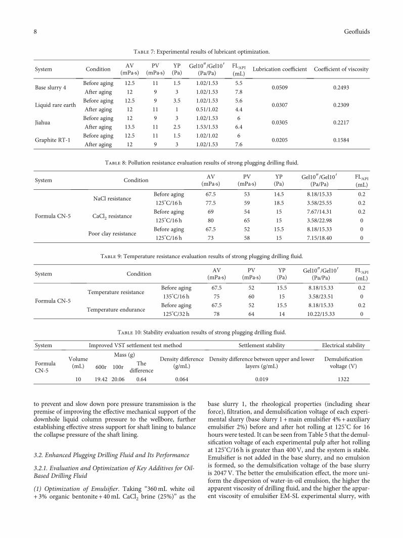
Table 7: Experimental results of lubricant optimization.
System ConditionAV
(mPa·s)PV
(mPa·s)YP(Pa)
Gel10″/Gel10′(Pa/Pa)
FLAPI(mL)
Lubrication coefficient Coefficient of viscosity
Base slurry 4Before aging 12.5 11 1.5 1.02/1.53 5.5
0.0509 0.2493After aging 12 9 3 1.02/1.53 7.8
Liquid rare earthBefore aging 12.5 9 3.5 1.02/1.53 5.6
0.0307 0.2309After aging 12 11 1 0.51/1.02 4.4
JiahuaBefore aging 12 9 3 1.02/1.53 6
0.0305 0.2217After aging 13.5 11 2.5 1.53/1.53 6.4
Graphite RT-1Before aging 12.5 11 1.5 1.02/1.02 6
0.0205 0.1584After aging 12 9 3 1.02/1.53 7.6
Table 8: Pollution resistance evaluation results of strong plugging drilling fluid.
System ConditionAV
(mPa·s)PV
(mPa·s)YP(Pa)
Gel10″/Gel10′(Pa/Pa)
FLAPI(mL)
Formula CN-5
NaCl resistanceBefore aging 67.5 53 14.5 8.18/15.33 0.2
125°C/16 h 77.5 59 18.5 3.58/25.55 0.2
CaCl2 resistanceBefore aging 69 54 15 7.67/14.31 0.2
125°C/16 h 80 65 15 3.58/22.98 0
Poor clay resistanceBefore aging 67.5 52 15.5 8.18/15.33 0
125°C/16 h 73 58 15 7.15/18.40 0
Table 9: Temperature resistance evaluation results of strong plugging drilling fluid.
System ConditionAV
(mPa·s)PV
(mPa·s)YP(Pa)
Gel10″/Gel10′(Pa/Pa)
FLAPI(mL)
Formula CN-5
Temperature resistanceBefore aging 67.5 52 15.5 8.18/15.33 0.2
135°C/16 h 75 60 15 3.58/23.51 0
Temperature enduranceBefore aging 67.5 52 15.5 8.18/15.33 0.2
125°C/32 h 78 64 14 10.22/15.33 0
Table 10: Stability evaluation results of strong plugging drilling fluid.
System Improved VST settlement test method Settlement stability Electrical stability
FormulaCN-5
Volume(mL)
Mass (g)Density difference
(g/mL)Density difference between upper and lower
layers (g/mL)Demulsificationvoltage (V)600r 100r
Thedifference
10 19.42 20.06 0.64 0.064 0.019 1322
8 Geofluids
the lowest filtration loss, so the emulsifier constructed by theformula is preferred.
(2) Optimization of Fluid Loss Reducer. With “360mL whiteoil+3% organic bentonite+4% main emulsifier+2% auxiliaryemulsifier+40mL CaCl2 brine (25%)” as base slurry 2, the rhe-ological properties of each experimental slurry (base slurry 2+2% fluid loss additive) before and after hot rolling at 125°Cfor 16 hours were tested. The experimental results in Table 6show that the apparent viscosity after aging is improved in dif-ferent degrees than before, and the fluid loss after adding thefluid loss reducer FR-BK is 6.4mL, and the fluid loss is the low-est among the preferred treatment agents. Moreover, it has acertain viscosity and shear force, which is helpful to the suspen-sion of cuttings and has excellent rheological properties, so thefluid loss reducer constructed by the formula is preferred.
(3) Optimization of Plugging Agent. According to the charac-teristics of microcracks and micropores in the Longmaxi For-mation rock samples, N-plugging agents, YX1200 andYX400, and other micro-nanoplugging agents wereresearched and selected, and 0.22μm and 0.45μm microfil-tration membranes were introduced to evaluate thepressure-bearing plugging ability of the plugging agents.With “360mL white oil + 3% organic bentonite + 4% mainemulsifier + 2% auxiliary emulsifier + 40mL CaCl2 brine+ 2% oil-based lignite-SL” as base slurry 3, the experimentalslurry (base slurry 3+5% plugging agent) was tested beforeand after hot rolling at 125°C for 16 hours. It can be seen
from Figures 4 and 5 that the API filtration loss of experi-mental slurry with the YX1200 plugging agent is 5.6mL,and the filtration loss through microporous membranes withpore diameters of 0.22μm and 0.45μm is 10mL and 9.6mL,respectively. Compared with other plugging agents, theYX1200 plugging agent has the lowest filtration loss and bet-ter plugging effect, so it is selected as the plugging agent forthe oil-based drilling fluid.
(4) Optimization of Lubricant. With “360mL white oil + 3%organic bentonite + 4% main emulsifier + 2% auxiliary emul-sifier + 40mL CaCl2 brine + 2% oil-based lignite-SL+5%plugging agent YX1200” as base slurry 4, each experimentalslurry (base slurry + 1.5% lubricant) was tested. The experi-mental results in Table 7 show that the lubricating coefficientand viscosity coefficient of the experimental slurry addedwith solid lubricant-BK are 0.0102 and 0.1495, respectively,which are lower than those of other lubricants. The graphiteRT-1 was selected as the lubricant for the next experiment.
3.2.2. Performance Evaluation of Enhanced Plugging DrillingFluid. By further optimizing the organic bentonite, pluggingagent, and viscosity reducer and optimizing the compatibilityof the system, an enhanced plugging drilling fluid system wasconstructed. It consists of 360mL white oil + 4% organic ben-tonite (BK) +4% main emulsifier (EM-SL) + 2% auxiliaryemulsifier (EM-SL) + 4% wetting agent + 2% quicklime+ 40mL CaCl2 brine + 4% oil-based fluid loss reducer(BK) + 4% plugging agent (YX1200) + 1.0% solid lubricantRT-1+ 1.5% flow pattern regulator + barite (the density isadjusted to 1.5 g/cm3), which is designated as Formula CN-5.
(1) Contamination Resistibility. By adding 10% NaCl, 1.0%CaCl2, and 8% poor clay (passing through 100-mesh sieve)into the Formula CN-5 drilling fluid system, the antipollu-tion ability of each system is evaluated by observing the
0 100 200 300 400 500 6000.00
0.05
0.10
0.15
0.20
0.25
0.30
0.35
0.40
0.45
Time (min)
Line
ar sw
ellin
g ca
paci
ty (m
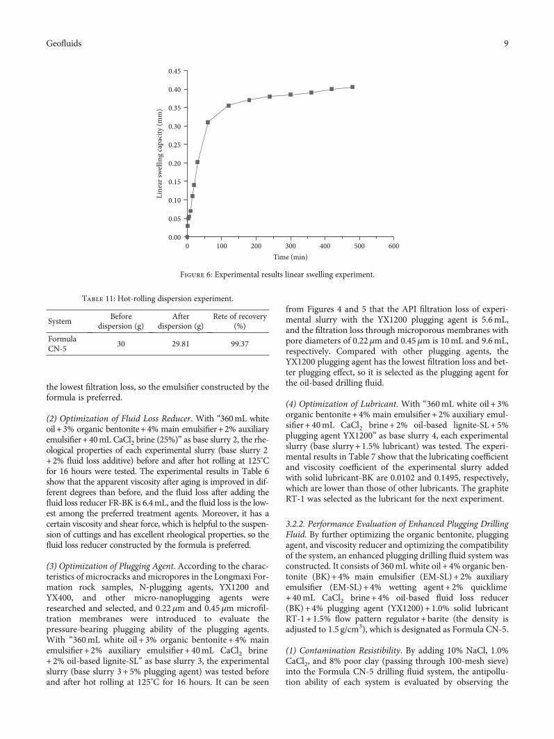
m)
Figure 6: Experimental results linear swelling experiment.
Table 11: Hot-rolling dispersion experiment.
SystemBefore
dispersion (g)After
dispersion (g)Rete of recovery
(%)
FormulaCN-5
30 29.81 99.37
9Geofluids
performance changes before and after hot rolling at 125°C for16 hours. The evaluation results are shown in Table 8.
The experimental data in Table 8 show that after adding10% NaCl into the Formula CN-5 drilling fluid system, theapparent viscosity of the system has little change, and its saltresistance is better. After adding 8% poor clay and 1.0% cal-cium chloride, the viscosity increased slightly, and it had cer-tain poor clay resistibility and calcium resistibility.
(2) Performance of Temperature Resistance. The rheologicalproperties and fluid loss of Formula CN-5 before and after hotrolling at 135°C for 16 hours and 125°C for 32 hours were tested.
It can be seen from Table 9 that the rheological fluid lossof the Formula CN-5 drilling fluid system has little changeafter hot rolling, which indicates that they have excellenttemperature resistance.
(3) Stability. The settlement stability, electrical stability, andimproved VST settlement of Formula CN-5 were tested.The experimental results are shown in Table 10.
The experimental results show that the Formula CN-5drilling fluid has good dynamic settlement stability, with adensity difference of 0.064 g/mL, density difference betweenupper and lower layers of 0.019 g/mL, and demulsificationvoltage of 1322V, which is more than 400V, which indicatesthat the system is stable.
(4) Inhibition.
(a) Linear swelling experiment: rock cuttings passingthrough 100 meshes in the Longmaxi Formationof CN22 well are selected, and the hydration andexpansion properties of the core in the complexsection of the Longmaxi Formation are tested bylinear swelling experiment and Formula CN-5 dril-ling fluid as the test solution. The results areshown in Figure 6.
Table 12: Fracture sealing evaluation results of strong plugging drilling fluid.
System Leaking bedPressure bearing time
(min)
Leakage stoppageDescription of plugging of leakage bedPressure
(MPa)Accumulated leakage
(mL)
FormulaCN-5
400μm crackblock
3 0 0
There was no drilling fluid leakage during theexperiment
3 0.5 0
3 1.0 0
3 2.0 0
3 3.0 0
3 4.0 0
3 5.0 0
Figure 7: Fracture sealing evaluation results of strong plugging drilling fluid. Evaluation of leakage and plugging performance of 400 μmmicrofractures with Formula CN-5 drilling fluid.
Figure 8: Sealing sand bed test results of strong plugging drillingfluid.
10 Geofluids

(b) Hot-rolling dispersion experiment: rock cuttings pass-ing 2-5mm mesh in the CN22 well of the LongmaxiFormation were selected, and the hydration anddispersion inhibition performance of the FormulaCN-5 drilling fluid was evaluated by the hot-rolling dispersion experiment. The results areshown in Table 11.
It can be seen from Figure 6 and Table 10 that the For-mula CN-5 drilling fluid system has a small hydration expan-sion amount, and the rolling recovery rate of cuttings isgreater than 95%, indicating that the drilling fluid system stillhas a strong ability to inhibit hydration expansion and hydra-tion dispersion.
(5) Performance of Leakage Prevention and Plugging.
(a) Evaluation of plugging performance of fractured leak-age: using a high-temperature and high-pressure(HTHP) plugging simulation experimental device,the plugging and bearing capacity of Formula CN-5drilling fluid to 400μm microcracks is evaluated.The experimental results are shown in Table 12 andFigure 7.
The Formula CN-5 drilling fluid system has a certainplugging ability for 400μm fractures, and there is no leakageduring the experiment, and the average invasion depth isshallow.
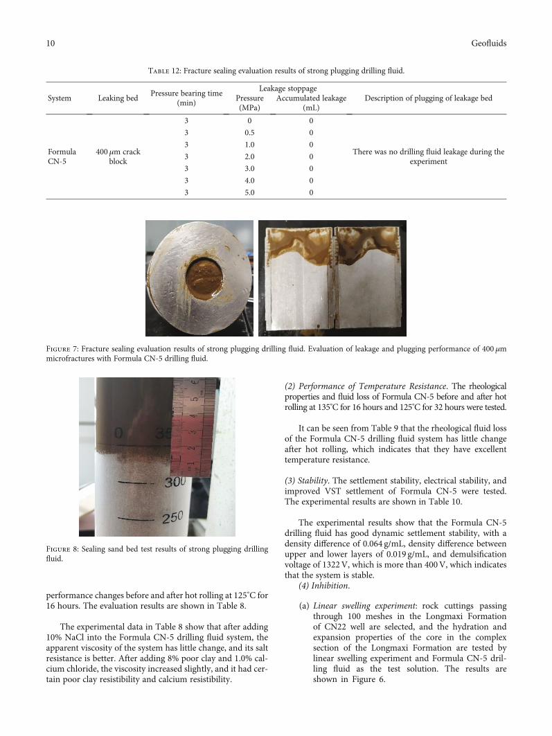
(b) Evaluation of permeability leakage plugging perfor-mance: through sealing of the sand bed instrument,40-60-mesh sieve fine sand is selected to evaluatethe leakage prevention performance of optimizeddrilling fluid permeability leakage. The experimentalresults are shown in Figure 8. According to theanalysis of sand bed plugging experiment results,the average invasion depth of the Formula CN-5drilling fluid system is 7mm, and the invasion isshallow, which has strong permeability pluggingperformance.
(c) Experimental method for plugging evaluation ofmicro-nanopores and fractures: according to thecharacteristics of micro-nanopores and fractures inshale formation, the plugging ability of the FormulaCN-5 oil-based drilling fluid was tested by using amicroporous filter membrane instead of API filterpaper to simulate the fracture and micropore, andthe lost volume and bearing capacity were taken asevaluation indexes. The experimental results showthat the instantaneous filtration loss of the FormulaCN-5 drilling fluid is 0mL after 0.45μm and0.22μmmicroporous membrane evaluation systems,and the filtration loss is still 0mL after 30min. Themud cake produced by the microporous membraneis shown in Figure 9. Experiments show that the For-mula CN-5 drilling fluid system has certain ability ofplugging microcracks and micropores.
As discussed before, mineral composition analysis showsthat the rock samples of the Longmaxi Formation are mainlyquartz, with an average content of 32.46%, calcite 19.85%,and clay mineral 15.31%. The rock samples of the WufengFormation are mainly quartz, with an average content of33%, calcite content of 16.25%, and clay mineral content of18%. The microstructure analysis shows that the rock sam-ples of the Longmaxi Formation have compact cementation,and the intergranular pores do not develop, but there arecracks and dissolution pores and fractures, and occasionally,there are salt crystals in the pores. Hydration swelling anddispersion tests show that the hydration swelling rate ofLongmaxi Formation rock samples in 8 wells in the field is3.3% on average, with weak swelling, and the dispersionrecovery rate of Longmaxi Formation rock samples is27.63% on average, with strong dispersion.
Based on the analysis of well conditions and drilling fluidperformance of each well, in order to reduce downhole stick-ing and drilling leakage, the functional indexes of oil-baseddrilling fluid in the Changning block are preliminarily rec-ommended as follows: shale expansion rate is controlledbelow 0.25%, lubrication coefficient is controlled below0.040, shale recovery rate is controlled above 99% (different
(a) 0.45 μm microporous membrane (b) 0.22 μm microporous membrane
Figure 9: Experimental results of microporous filter test.
11Geofluids

rock samples will vary), sand bed invasion depth is controlledbelow 12mm, and bearing capacity for 200μm and 400μmfractures is greater than 5MPa.
The constructed oil-based drilling fluid system “360mLwhite oil + 4% organic bentonite (BK) +4% main emulsifier(EM-SL) + 2% auxiliary emulsifier (EM-SL) + 4% wettingagent + 2% quicklime +40mL CaCl2 brine + 4% oil-basedfluid loss reducer (BK) +4% plugging agent(YX1200) + 1.0% solid lubricant RT-1+ 1.5% flow patternregulator + barite (the density is adjusted to 1.5 g/cm3)” inthe Changning block is stable and easy to maintain andcontrol.
Due to the addition of micron-sized plugging materials, ithas certain plugging ability for microcracks and micropores.If you want the oil-based drilling fluid system to have betterplugging and anticollapse performance, the plugging agentof the oil-based drilling fluid should be selected from lipo-philic micro-nanomaterials, and the experimental methodsand means for evaluating micro-nanomaterials should befurther developed.
4. Conclusion
In this paper, the causes of wellbore instability of shale gashorizontal section in the Changning block are analysed, andthe corresponding solutions are put forward. A set of exper-imental methods for evaluating oil-based drilling fluid sys-tem is summarized, and a set of an oil-based drilling fluidsystem suitable for shale formation with microfracture devel-opment is constructed. The Longmaxi Formation andWufeng Formation are hard and brittle shales mainly com-posed of illite, with developed microfractures and stronghydration of some formations. When the drilling fluid filtratedeeply intrudes into the formation along the microfractures,it will cause hydration of shale, which weakens the cementa-tion force between particles, while hydration stress caused byhydration makes the wellbore lose balance, resulting in com-plex situations such as wellbore dropping and collapse.Besides, this paper puts forward the plugging theory of“strengthening plugging micropores, inhibiting filtrate inva-sion, and retarding pressure transmission.” It emphasizesthe combination of physical and chemical plugging and effec-tive stress supporting of the wellbore and enhanced inhibi-tion of surface hydration. Strengthening the sealing toprevent and slow down of pore pressure transmission is thepremise of improving the effective mechanical support ofdownhole liquid column pressure to the wellbore. Effectivestress needs to be further established to support the shaft lin-ing to balance the collapse pressure of the shaft lining.Finally, the shale gas oil-based drilling fluid system con-structed in this paper has strong plugging ability, excellentinhibition and temperature resistance, preferable contamina-tion resistibility, and good rheological property and filtrationwall-building property and is easy to control.
Nomenclature
AV: Apparent viscosity (mPa·s)PV: Plastic viscosity (mPa·s)
YP: Yield point (Pa)FLAPI: API filtration (mL).
Data Availability
The experimental data used in this paper are true and effec-tive, and all come from experimental research.
Conflicts of Interest
The authors declare that they have no conflicts of interest.
Acknowledgments
This work was financially supported by the National NaturalScience Foundation of China (No. 51974351; No. 51704322;Major Program, No. 51991361), the National Science andTechnology Major Project of China (No. 2016ZX05040-005), and PCSIRT (IRT_14R58).
References
[1] X. Ma and J. Xie, “Shale gas exploration and developmentprogress and development prospect in southern Sichuan,”Petroleum Exploration and Development, vol. 45, no. 1,pp. 161–169, 2018.
[2] F. Pengfei, Study on the collapse and instability mechanism ofshale horizontal wells in WY-CN Longmaxi formation, South-west Petroleum University, 2016.
[3] L. Jingping and S. Jinsheng, “Hydration instability mechanismand inhibition method of shale gas reservoir formation,” Dril-ling Fluid and Completion Fluid, vol. 33, no. 3, pp. 25–29, 2016.
[4] C. Cao, M. Zhang, L. Li et al., “Tracing the sources and evolu-tion processes of shale gas by coupling stable (c,H) and noblegas isotopic compositions: cases from Weiyuan and changingin Sichuan basin, China,” Journal of Natural Gas Science andEngineering, vol. 78, no. 5, pp. 23–26, 2020.
[5] X. Wang, B. Dongqing, S. Yunchao et al., “All-oil-based dril-ling fluid system for enhanced plugging of shale gas wells —taking Weiyuan block in Changning-Weiyuan National ShaleGas Demonstration Zone as an example,” Natural Gas Indus-try, vol. 40, no. 6, pp. 107–114, 2020.
[6] L. Liang, Z. Dalin, L. Xiangjun et al., “Study on mechanicalproperties and failure modes of Longmaxi formation shale,”Chinese Journal of Underground Space and Engineering,vol. 13, no. 1, pp. 108–116, 2017.
[7] S. Jinsheng, L. Jingping, Y. Lili et al., “Present situation of shalegas well water-based drilling fluid technology at home andabroad and development direction in China,” Drilling Fluidand Completion Fluid, vol. 33, no. 5, pp. 1–8, 2016.
[8] H. C. H. Dreley, “A laboratory investigation of borehole stabil-ity,” Journal of Technology, vol. 21, no. 7, pp. 883–892, 1969.
[9] X. Chen, C. P. Tan, and C. Detournay, “A study on wellborestability in fractured rock masses with impact of mud infiltra-tion,” Journal of Petroleum Science and Engineering, vol. 38,no. 3-4, pp. 145–154, 2003.
[10] X. Chen, Q. Yang, K. B. Qiu, and J. L. Feng, “An anisotropicstrength criterion for jointed rock masses and its applicationin wellbore stability analyses,” International Journal forNumerical and Analytical Methods in Geomechanics, vol. 32,no. 6, pp. 607–631, 2008.
12 Geofluids

[11] J. Zhang, “Borehole stability analysis accounting for aniso-tropic in drilling to weak bedding planes,” International Jour-nal of Rock Mechanics and Mining Sciences, vol. 22, no. 3,pp. 160–170, 2013.
[12] O. Gaede, F. Karpfinger, J. Jocker, and R. Prioul, “Comparisonbetween analytical and 3D finite element solutions for bore-hole stresses in anisotropic elastic rock,” International Journalof Rock Mechanics and Mining Sciences, vol. 51, pp. 53–63,2012.
[13] Z. Haifeng, Y.Wang, and F. Fan, “Oil-based drilling fluid technol-ogy for strong plugging of shale gas horizontal wells,”Natural GasTechnology and Economics, vol. 12, no. 5, pp. 33–36, 2018.
[14] Z. Feng, Z. Yang, and S. Luo, “Drilling difficulties and counter-measures in Changning shale gas horizontal section,” Drillingand Production Technology, vol. 43, Supplement 1, pp. 4–7,2020.
[15] T. Guowang, G. Weichao, and P. Yu, “Research and applica-tion of strong plugging oil-based drilling fluid system,” Pro-specting Engineering (Geotechnical Drilling and ExcavationEngineering), vol. 44, no. 11, pp. 21–25, 2017.
[16] W. Yinwu and Z. Xue, “Application of oil-based drilling fluidtechnology in shale gas wells in western Sichuan,” LiaoningChemical Industry, vol. 45, no. 6, pp. 773–776, 2016.
[17] Z. Gaobo, Q. Gao, and Q. Ma, “Measures to improve the anti-collapse performance of oil-based drilling fluid in shale gasformation,” Drilling Fluid and Completion Fluid, vol. 36,no. 2, pp. 141–147, 2019.
[18] M. Meng, Z. Zamanipour, S. Miska, M. Yu, and E. M. Ozbayo-glu, “Dynamic stress distribution around the wellbore influ-enced by surge/swab pressure,” Journal of Petroleum Scienceand Engineering, vol. 172, pp. 1077–1091, 2019.
[19] Z. Hanyi, Q. Zhengsong, H. Wei’an et al., “Development andfeatures of amine shale inhibitors,” Petroleum Drilling Tech-niques, vol. 38, no. 1, pp. 104–108, 2010.
[20] Z. Hanyi, Q. Zhengsong, H. Wei’an, F. W. Wang, and X. B.Zhang, “Experimental evaluation on polyamine water-baseddrilling fluid,” Oilfield Chemistry, vol. 27, no. 2, pp. 119–123,2010.
[21] J.-g. Xu, Z. Qiu, X. Zhao, H. Zhong, and W. Huang, “Study of1-octyl-3-methylimidazolium bromide for inhibiting shalehydration and dispersion,” Journal of Petroleum Science andEngineering, vol. 177, no. 2, pp. 208–214, 2019.
13Geofluids