Embed Size (px)
Citation preview

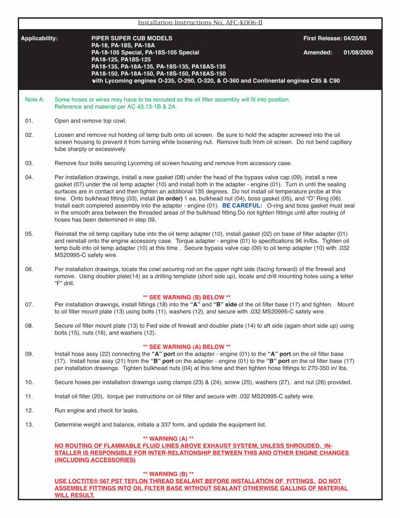
Oil Filter Kit AFC-K006Applicability: PIPER SUPER CUB MODELS First Release: 04/25/93 PA-18, PA-18S, PA-18A PA-18-105 Special, PA-18S-105 Special Amended: 01/08/2000 PA18-125, PA18S-125 PA18-135, PA-18A-135, PA-18S-135, PA18AS-135 PA18-150, PA-18A-150, PA-18S-150, PA18AS-150 with Lycoming engines O-235, O-290, O-320, & O-360 engines.
0102
03
04
06
05
07
0809
10
11 12
13
14 15 16
18
17
19
20
21
22
23
24
251226 27
Parts List No. AFC-K006-PLIndex Part Number Description Quantity01. LYC-10 Adapter- Engine, Full Flow (1)02. 61173 Adapter Base Gasket (1)03. AN837-8D Bulkhead Fitting, 45° (2)04. AN6289-8D Bulkhead Nut (2)05. MS28773-08 Boss Gasket, Teflon (2)06. MS9387-08 “O” Rings, Viton (2)07. MS35769-11 Gasket, Oil Temperature Sensor (1)08. MS35769-21 Gasket, Thermostatic Valve (1)09. CAP-1350 Bypass Valve Cap (1)10 OTA-527 Oil Temp Adapter (1)11. AN4H-4A Bolts, Drilled Head (4)12. AN960-416 Flat Washers (16)13. OFM-11 Oil Filter Mount Plate, Vertical (1)14. DBL-10 Doubler Plate (1)15. AN4-5A Bolts (6)16. MS20365-428A Locknuts (6)17. OFB-10 Oil Filter Base (1)18. MS20822-8D Fitting, 90° (2)19. OFS-10 Oil Filter Stud (1)20. AFC-500 Oil Filter, or Equivalent [Champion CH48108] (1)21. F13000008-0152 Hose Assy, TSO'D, Firesleeved (1)22. F13000008-0172 Hose Assy, TSO'D, Firesleeved (1)23. MS21919WDG-14 Clamp, Adel (1)24. MS21919WDG-12 Clamp, Adel (1)25. AN3-4A Bolt (1)26. MS20365-1032A Locknut (1)27. AN960-10 Washer (2)28. 56707 Loctite 267® Thread Sealant (1)29. AFC-K006-II Installation Instructions (1)30. AFC-K006-MI Instructions for Continued Airworthiness (1)31. AFC-K006-PL Parts List (1)

Parts List No. AFC-K006-PLIndex Part Number Description Quantity01a. CON-10 Full Flow Engine Adapter [1-3/4"-16 Threads] (1)02a. RNG-10 Sealing Ring [1-3/4"-16 Threads] (1)03a. M83248/1-223 Sealing O-Ring (1)04. M83248/1-016 O-Ring, Nosepiece (1)05a. EXT-10 Oil Screen Adapter - A50, A65, A75, A80, C75, C85, C90, C125, O-200, IO240 (1)06a. M83248/1-126 or O-Ring, Use w/EXT-10 or 1Ring (1)07a. AN837-10D or 45° Bulkhead Fitting (2)07b. AN833-10D or 90° Bulkhead Fitting (Opt)07c. AN815-10D Union (Opt)08. AN6289-10D Bulkhead Nut (2)09. MS28773-10 Boss Gasket (2)10. MS9387-10 O-Ring (2)11. AN776-10D 90° Fitting (1)12a. TPA-775 Temp Probe Adapter (Opt)12b. TPA-776 Temp Probe Adapter & Gasket (Opt)13a. MS35769-18 Temp Probe Adapter Gasket (Opt)14a. OTA-527 or 5/8" Long Oil Temp Adapter (Opt)14b. OTA-2250 2-1/4" Long Oil Temp Adapter (Opt)15 MS35769-11 Oil Temp Adapter Gasket (Opt)16. AN4H-4A Drilled Head Bolts (4)17. AN960-416 Flat Washers (16)18. OFB-11 Oil Filter Base, -10 Port (1)19a. MS20822-10D or 90° Elbow (1)19b. MS20823-10D or 45° Elbow (1)19c. AN816-10D Flared Tube Nipple (Opt)20. OFS-10 Oil Filter Stud (1)21a. AFC-500 or Std Oil Filter or Equivalent [Champion CH48108] (1)22a. OFM-10 Horizontal Oil Filter Mount (1)22b. OFM-11 Vertical Oil Filter Mount (1)23. DBL-10 Doubler Plate (1)24. AN4-5A Bolts (6)25. MS20365-428A Locknuts (6)26b. F13000010-0xxz Titeflex® Teflon Hose Assy with Fire Sleeving. (Opt)31. 56707 Loctite® 567 PST Teflon Thread Sealant (1)
Applicability: PIPER SUPER CUB MODELS First Release: 04/25/93 PA-18, PA-18S, PA-18A PA-18-105 Special, PA-18S-105 Special Amended: 01/08/2000 PA18-125, PA18S-125 PA18-135, PA-18A-135, PA-18S-135, PA18AS-135 PA18-150, PA-18A-150, PA-18S-150, PA18AS-150 with Continental engines C85 & C90
Installation Instructions No. AFC-K006-II
Note A: Some hoses or wires may have to be rerouted so the oil filter assembly will fit into position. Reference and material per AC 43.13-1B & 2A.
01. Open and remove top cowl.
02. Loosen and remove nut holding oil temp bulb onto oil screen. Be sure to hold the adapter screwed into the oil screen housing to prevent it from turning while loosening nut. Remove bulb from oil screen. Do not bend capillary tube sharply or excessively.
03. Remove four bolts securing Lycoming oil screen housing and remove from accessory case.
04. Per installation drawings, install a new gasket (08) under the head of the bypass valve cap (09), install a new gasket (07) under the oil temp adapter (10) and install both in the adapter - engine (01). Turn in until the sealing surfaces are in contact and then tighten an additional 135 degrees. Do not install oil temperature probe at this time. Onto bulkhead fitting (03), install (in order) 1 ea. bulkhead nut (04), boss gasket (05), and “O” Ring (06). Install each completed assembly into the adapter - engine (01). BE CAREFUL: O-ring and boss gasket must seal in the smooth area between the threaded areas of the bulkhead fitting.Do not tighten fittings until after routing of hoses has been determined in step 09.
05. Reinstall the oil temp capillary tube into the oil temp adapter (10), install gasket (02) on base of filter adapter (01) and reinstall onto the engine accessory case. Torque adapter - engine (01) to specifications 96 in/lbs. Tighten oil temp bulb into oil temp adapter (10) at this time . Secure bypass valve cap (09) to oil temp adapter (10) with .032 MS20995-C safety wire.
06. Per installation drawings, locate the cowl securing rod on the upper right side (facing forward) of the firewall and remove. Using doubler plate(14) as a drilling template (short side up), locate and drill mounting holes using a letter “F” drill.
** SEE WARNING (B) BELOW **07. Per installation drawings, install fittings (18) into the “A” and “B” side of the oil filter base (17) and tighten. Mount
to oil filter mount plate (13) using bolts (11), washers (12), and secure with .032 MS20995-C safety wire.
08. Secure oil filter mount plate (13) to Fwd side of firewall and doubler plate (14) to aft side (again short side up) using bolts (15), nuts (16), and washers (12).
** SEE WARNING (A) BELOW **09. Install hose assy (22) connecting the “A” port on the adapter - engine (01) to the “A” port on the oil filter base
(17). Install hose assy (21) from the “B” port on the adapter - engine (01) to the “B” port on the oil filter base (17) per installation drawings. Tighten bulkhead nuts (04) at this time and then tighten hose fittings to 270-350 in/ lbs.
10. Secure hoses per installation drawings using clamps (23) & (24), screw (25), washers (27), and nut (26) provided.
11. Install oil filter (20), torque per instructions on oil filter and secure with .032 MS20995-C safety wire.
12. Run engine and check for leaks.
13. Determine weight and balance, initiate a 337 form, and update the equipment list.
** WARNING (A) ** NO ROUTING OF FLAMMABLE FLUID LINES ABOVE EXHAUST SYSTEM, UNLESS SHROUDED. IN-
STALLER IS RESPONSIBLE FOR INTER-RELATIONSHIP BETWEEN THIS AND OTHER ENGINE CHANGES (INCLUDING ACCESSORIES)
** WARNING (B) ** USE LOCTITE® 567 PST TEFLON THREAD SEALANT BEFORE INSTALLATION OF FITTINGS. DO NOT
ASSEMBLE FITTINGS INTO OIL FILTER BASE WITHOUT SEALANT OTHERWISE GALLING OF MATERIAL WILL RESULT.
Applicability: PIPER SUPER CUB MODELS First Release: 04/25/93 PA-18, PA-18S, PA-18A PA-18-105 Special, PA-18S-105 Special Amended: 01/08/2000 PA18-125, PA18S-125 PA18-135, PA-18A-135, PA-18S-135, PA18AS-135 PA18-150, PA-18A-150, PA-18S-150, PA18AS-150 with Lycoming engines O-235, O-290, O-320, & O-360 and Continental engines C85 & C90

Note A: Some hoses or wires may have to be rerouted so the oil filter assembly will fit into position. Reference and material per AC 43.13-1B & 2A.
01. Remove the Continental screen assembly P/N A3568.02. Clean Screen housing and gasket surface. Assemble Engine Adapter (01a) as follows: (A) Lubricate threads of Engine Adapter (01a) and Sealing Ring (02a) with suitable lubricant. (B) Thread Sealing Ring (02a) onto Engine Adapter (01a) past smooth area , onto second set of threads. (C) Install lightly oiled O-Ring, (03). and position in the smooth area between the upper and lower threads. (D) Run Sealing Ring (02a) down against O-ring. [Assure O-ring is still centered in non threaded area.] (E) Insert lightly oiled O-ring, (04) into groove inside of center opening of Engine Adapter (01a)
03. Install lightly oiled O-ring (06a) onto Oil Screen Adapter (05a) and insert into screen chamber of engine. When seated correctly, tube will extend above face of engine accessory case approximately 1/4". As adapter is inserted, resis-
tance will be met. Continue pressure indicating compression of O-Ring (06a)- until adapter is seated in lower screen seat.
04. Thread engine adapter (01a) into engine oil screen opening being sure that oil screen adapter (05b) is started in center of the opening. Screw in engine adapter (01a) until light resistance indicates that O-ring (03) is seated on the accessory case. Orient the engine adapter (01a) as necessary, being careful not to screw the engine adapter (01a) in or out more than 1/2 turn from present position. This assures that the O-Ring is still centered in the non threaded area. Do not tighten sealing ring yet.
05. Onto each bulkhead fitting (07a) or (07b), install in order 1 ea. bulkhead nut (08), boss gasket (09), and O-Ring (10). If using a union (07c), install O-Ring (10) only . When assembled correctly, the O-Ring (10) is positioned in the center of the non-threaded area, between the upper set of threads and the lower set of threads on the bulkhead fitting. Install each completed assembly into the engine adapter (01a) and located towards intended direction of hoses.
CAUTION: O-ring only seals in the center of the non-threaded area between the upper set threads and lower set of threads on the bulk-head fitting. Failure to position the O-Ring in this area, may cause a small oil leak.
06. On A50 & A65 engines, remove the oil drain plug and relocate the oil temperature capillary tube and oil temp adapter using oil temp gasket (15) provided and safety wire.
07. On A75, A80, C75, C85, C90, & O200 engines, remove one of the Continental P/N 532432 plugs located in the front of the en-gine which caps off access to the oil gallery. Remove the brass oil temp adapter nut from the existing oil screen and relocate the oil temperature bulb to this location. Torque to specs and secure.
NOTE D: Capillary tube may be kept at present location provided sufficient space exists between the engine and firewall. To utilize the existing location, 1 ea. 90° Fitting (11), Temp Probe Adapter (12), Oil Temp Adapter Gasket(14), and 2 ea. Temp Probe Adapter Gasket (13a) must be used per installation drawings.
08. Remove the oil drain plug and relocate the oil temperature capillary tube and oil temp adapter using oil temp gasket (15) pro-vided and safety wire.
***** SEE WARNING (A) ABOVE *****09. Using the horizontal oil filter mount (22a) or vertical oil filter mount (22b) as a drilling template, locate and drill mounting holes
using a letter “F” drill.10a. Secure vertical oil filter mount (22b) to Fwd side of firewall and doubler plate (23) to Aft side of firewall using bolts (24), washers
(17), and locknuts (25). OR10b. Secure oil filter base (18) to Fwd side of firewall and horizontal oil filter mount plate (22a) to rear side using bolts (16), washers
(17) and secure with .032 MS20995-C safety wire.***** SEE WARNING (B) ABOVE *****
11. Install any combination of fitting (19a), (19b), or (19c) into oil filter base (18). Mount to vertical oil filter mount (22b.) using bolts (16), washers (17), and secure with .032 MS20995-C safety wire.
12. Determine hose lengths and order appropriate hoses. Ex: P/N for a 24-7/8" long firesleeved hose with straight swivel fittings at each end of the hose is F13000010-0247.
***** SEE WARNING (C) ABOVE *****13. Install 2 ea. hose assyʼs (26a) or (26b) connecting the “A” port on the filter adapter to the “A” port on the oil filter base and the
“B” port on the filter adapter to the “B” port on the oil filter base per installation drawings and tighten hose fittings to 270-350 in/ lbs.
Applicability: PIPER SUPER CUB MODELS First Release: 04/25/93 PA-18, PA-18S, PA-18A PA-18-105 Special, PA-18S-105 Special Amended: 01/08/2000 PA18-125, PA18S-125 PA18-135, PA-18A-135, PA-18S-135, PA18AS-135 PA18-150, PA-18A-150, PA-18S-150, PA18AS-150 with Lycoming engines O-235, O-290, O-320, & O-360 and Continental engines C85 & C90

14. After hoses have taken natural set, and hose fittings tightened, tighten sealing ring (02a) with 2" Pin Spanner wrench. Do not over-tighten. Secure with safety wire. Note: Approximately 1/4-1/2 turn is all that is needed to compress the Viton O-ring properly and no leakage will occur.
15. Install oil filter (21a), torque per instructions on oil filter and secure with safety wire.
16. Run engine and check for leaks.
17. Determine weight and balance, initiate 337 form, and update the equipment list.
Typical installation in aircaft using C75, C85, C90, C125 & O-200 Continental engines keeping oil temp probe at present location. Also can be used in A50-A75 engines where there is at least 4.25" from the accy case to the firewall.
MAT
ERIA
L LI
STIn
dex
Par
t Num
ber
D
escr
iptio
n01
a.
CO
N-1
0
E
ngin
e Ad
apte
r - [1
-3/4
"-16
Thre
ads]
01b.
C
ON
-11
Eng
ine
Adap
ter
-[1-1
3/16
"-16
Thre
ads]
02a.
R
NG
-10
Sea
ling
Rin
g [1
-3/4
"-16
Thre
ads]
02b.
R
NG
-11
Sea
ling
Rin
g [1
-13/
16"-1
6 Th
read
s]03
.
M83
248/
1-22
3
Sea
ling
Rin
g O
-Rin
g04
.
M83
248/
1-01
6
Nos
epie
ce O
-Rin
g05
a.
EXT
-10
O
il Sc
reen
Ada
pter
05b.
E
XT-1
1
Oil
Scre
en A
dapt
er05
c.
EXT
-12
O
il Sc
reen
Ada
pter
05d.
E
XT-1
4
Oil
Scre
en A
dapt
er06
a.
M83
248/
1-12
6
O-R
ing,
Use
w/E
XT-1
0 &
EXT-
12 A
dapt
er06
b.
M83
248/
1-12
8
O-R
ing,
Use
w/E
XT-1
1 &
EXT-
14 A
dapt
er07
a
AN
837-
10D
45
° Bul
khea
d Fi
tting
07b.
A
N83
3-10
D
90° B
ulkh
ead
Fitti
ng07
c.
AN
815-
10D
U
nion
08.
A
N62
89-1
0D
B
ulkh
ead
Nut
09.
M
S287
73-1
0
Bo
ss G
aske
t10
.
MS9
387-
10
O-R
ing
11.
A
N77
6-10
D
90° F
ittin
g12
a.
TPA
-775
Tem
p Pr
obe
Adap
ter
12b.
T
PA-7
76
T
emp
Prob
e Ad
apte
r & G
aske
t13
.
MS3
5769
-18
Tem
p Pr
obe
Adap
ter G
aske
t14
.
OTA
-527
Oil T
emp
Adap
ter
15.
M
S357
69-1
1
O
il Tem
p Ad
apte
r Gas
ket
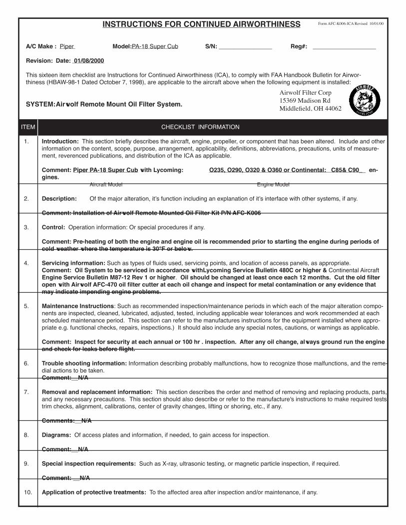
INSTRUCTIONS FOR CONTINUED AIRWORTHINESS
A/C Make : Piper Model:PA-18 Super Cub S/N: ________________ Reg#: ___________________
Revision: Date: 01/08/2000
This sixteen item checklist are Instructions for Continued Airworthiness (ICA), to comply with FAA Handbook Bulletin for Airwor-thiness (HBAW-98-1 Dated October 7, 1998), are applicable to the aircraft above when the following equipment is installed:
SYSTEM:Airwolf Remote Mount Oil Filter System.
ITEM CHECKLIST INFORMATION
1. Introduction: This section briefly describes the aircraft, engine, propeller, or component that has been altered. Include and other information on the content, scope, purpose, arrangement, applicability, definitions, abbreviations, precautions, units of measure-ment, reverenced publications, and distribution of the ICA as applicable.
Comment: Piper PA-18 Super Cub with Lycoming: O235, O290, O320 & O360 or Continental: C85& C90__ en-gines.
Aircraft Model Engine Model
2. Description: Of the major alteration, itʼs function including an explanation of itʼs interface with other systems, if any.
Comment: Installation of Airwolf Remote Mounted Oil Filter Kit P/N AFC-K006
3. Control: Operation information: Or special procedures if any.
Comment: Pre-heating of both the engine and engine oil is recommended prior to starting the engine during periods of cold weather where the temperature is 30°F or below.
4. Servicing information: Such as types of fluids used, servicing points, and location of access panels, as appropriate. Comment: Oil System to be serviced in accordance withLycoming Service Bulletin 480C or higher & Continental Aircraft
Engine Service Bulletin M87-12 Rev 1 or higher. Oil should be changed at least once each 12 months. Cut the old filter open with Airwolf AFC-470 oil filter cutter at each oil change and inspect for metal contamination or any evidence that may indicate impending engine problems.
5. Maintenance Instructions: Such as recommended inspection/maintenance periods in which each of the major alteration compo-nents are inspected, cleaned, lubricated, adjusted, tested, including applicable wear tolerances and work recommended at each scheduled maintenance period. This section can refer to the manufactures instructions for the equipment installed where appro-priate e.g. functional checks, repairs, inspections.) It should also include any special notes, cautions, or warnings as applicable.
Comment: Inspect for security at each annual or 100 hr . inspection. After any oil change, always ground run the engine
and check for leaks before flight.
6. Trouble shooting information: Information describing probably malfunctions, how to recognize those malfunctions, and the reme-dial actions to be taken.
Comment:__N/A
7. Removal and replacement information: This section describes the order and method of removing and replacing products, parts, and any necessary precautions. This section should also describe or refer to the manufacture's instructions to make required tests, trim checks, alignment, calibrations, center of gravity changes, lifting or shoring, etc., if any.
Comments:__N/A
8. Diagrams: Of access plates and information, if needed, to gain access for inspection. Comment:__N/A
9. Special inspection requirements: Such as X-ray, ultrasonic testing, or magnetic particle inspection, if required.
Comment: __N/A
10. Application of protective treatments: To the affected area after inspection and/or maintenance, if any.
Airwolf Filter Corp15369 Madison RdMiddlefield, OH 44062
Form AFC-K006-ICA Revised 10/01/00

11. Data: Relative to structural fasteners such as type, torque, and installation requirements if any.
Comment:__N/A
12. List of special tools: Special tools that are required, if any.
Comment:__N/A
13. For commuter category aircraft: The following additional information must be furnished, as applicable: A. Electrical Loads B. Methods of balancing flight controls. C. Identification of primary and secondary structures> D. Special repair methods applicable to the airplane.
Comment:__N/A
14. Recommended overhaul periods: Are required to be noted on the ICA when an overhaul period has been set by the manu-facturer of a component, or equipment. If there is no overhaul period, the ICA should state for item 14: “No additional overhaul time limitations.”
Comment:__N/A
15. Airworthiness Limitation Section: Include any “approved” airworthiness limitations identified by the manufacturer of FAA type Certificate Holding Office (e.g., An STC incorporated in a larger field approved major alteration may have an airworthiness limi-tation.) The FAA inspector should not establish, alter, or cancel airworthiness limitations without coordinating with the appropriate FAA type Certificate Holding Office. If there are no changes to the airworthiness limitations, the ICA should state for item 15: “No additional airworthiness limitations” or “ Not Applicable.”
Comment:__N/A
16. Revision: This section should include information on how to revise the ICA. For example, a letter will be submitted to the local FSDO with a copy of the revised FAA Form 337 and revised ICA. The FAA inspection accepts the change by signing Block 3 and including the following statement: “The attached revised/new Instructions for Continued Airworthiness (date_______) for the above aircraft or component major alteration have been accepted by the FAA, superseding the Instructions for Continued Airworthiness (date_______).” Once the revision has been accepted, a maintenance record entry will be made, identifying the revision, its loca-tion, date of the Form 337.
Comment:__ A letter will be submitted to the local FSDO with a copy of the revised FAA Form 337 and revised ICA. The
FAA inspector accepts the change by signing Block 3 and including the following statement: “The attached revised/new Instructions for Continued Airworthiness (date_______) for the above aircraft or component major alteration have been accepted by the FAA, superseding the Instructions for Continued Airworthiness (date_______).” Once the revision has been accepted, a maintenance record entry will be made, identifying the revision, its location, date of the Form 337.
NOTE: Implementation and Record Keeping: For major alterations performed in accordance with FAA Field Approval policy, the owner op-
erator operating under part 91 is responsible for ensuring that the ICA is made part of the applicable section 92.409 inspection program for their aircraft. This is accomplished when a maintenance entry is made in the aircraftʼs maintenance record in accordance with sec-tion 43.9. This entry recorded the major alteration and identifies the original ICA location (e.g., Block 8 of FAA Form 337, dated 5/28/98) along with a statement that the ICA is now part of the aircraftʼs inspection/maintenance requirements.
For major alterations performed in accordance with field approval on air carrier aircraft, the air carrier operator is responsible for ensur-ing that the ICA is made part of the applicable inspection/maintenance program for their aircraft. If a procedure is not currently included in the operatorʼs manual to incorporate ICA, this process will need to be appropriately addressed (i.e. the operator submits a revision to its maintenance program to the applicable certificate-holding district office (CHDO).
For aircraft inspected under an Approved Aircraft Inspection Program (AAIP), the operator will submit a change to the CHDO in accor-dance with section 135.419b).
For air carrier aircraft inspected using an annual/100 hour inspection program, a reference to the new ICA will be made in the aircraftʼs maintenance record in accordance with section 43.9. This entry records the major alteration and identifies the original ICA location (e.g., ICA are located/attached to Block 8 of FAA Form 337, dated 5/28/98). In addition, the operator will request a revision to the operatorʼs Operations Specifications, additional maintenance requirements, which incorporates the ICA into the inspection program.
INSTRUCTIONS FOR CONTINUED AIRWORTHINESS Form AFC-K006-ICA Revised 10/01/00

WEIGHT AND BALANCE REPORTPA-18
SUPER CUB
EQUIPMENT - ITEM LBS. LONG LONG REMOTE OIL FILTER 4.25 -29.0 -123.25
SURPLUS EQUIPMENT WEIGHT ARM-INCHES MOMENT - IN/LBS.

Airwolf Filter Corp.
MATERIAL LISTIndex Part Number Description Qty01. LYC-10 Adapter-Engine, Full Flow (1)02. 61173 Adapter Base Gasket (1)03. AN837-8D Bulkhead Fitting - 45° (2)04. AN6289-8D Bulkhead Nut (2)05. MS28773-08 Boss Gasket (2)06. MS9387-08 "O" Ring (2)07. MS35769-11 Gasket, Oil Temperature Sensor (1)08. MS35769-21 Gasket, Thermostatic Valve (1)09. CAP-1350 Cap, Bypass Valve (1)10. OTA-527 Oil Temp Adapter (1)
Assembly Drawing. LYC-10 Adapter - Engine, Full Flow
01.
04.
05.
06.
08.
07.
09.
10.
03.
ASSEMBLY DRAWING# AFC-D-0020
Airwolf Filter Corp.
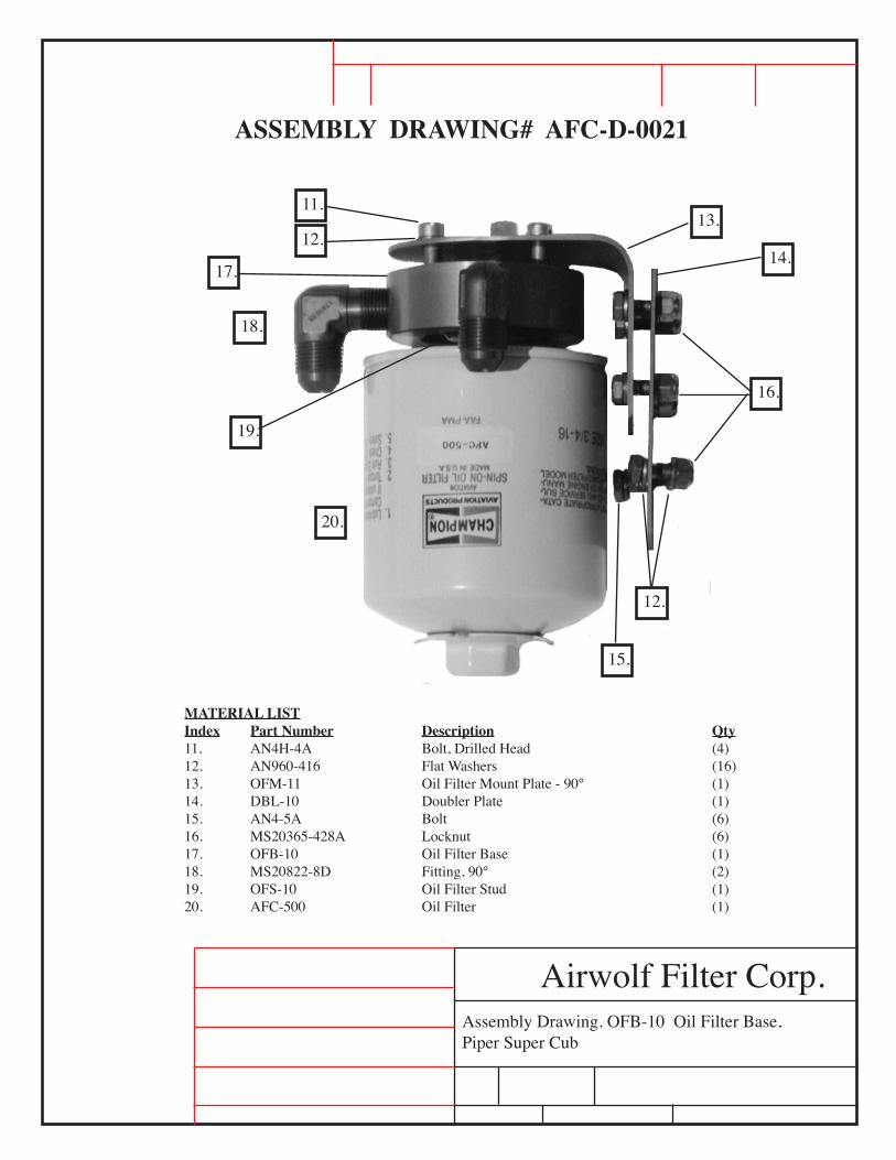
MATERIAL LISTIndex Part Number Description Qty11. AN4H-4A Bolt, Drilled Head (4)12. AN960-416 Flat Washers (16)13. OFM-11 Oil Filter Mount Plate - 90° (1)14. DBL-10 Doubler Plate (1)15. AN4-5A Bolt (6)16. MS20365-428A Locknut (6)17. OFB-10 Oil Filter Base (1)18. MS20822-8D Fitting, 90° (2)19. OFS-10 Oil Filter Stud (1)20. AFC-500 Oil Filter (1)
18.
20.
16.
12.
15.
13.11.
12.14.
17.
19.
Assembly Drawing. OFB-10 Oil Filter Base, Piper Super Cub
ASSEMBLY DRAWING# AFC-D-0021

Installation Drawing. OFB-10, OFM-11 &Hose Assemblies.
Airwolf Filter Corp.
MATERIAL LISTIndex Part Number Description Qty21. F13000008-0152 Hose Assy w/Firesleeving TSO'D (1)22. F13000008-0172 Hose Assy w/Firesleeving TSO'D (1)23. MS21919WDG-14 Adel Clamp (1)24. MS21919WDG-12 Adel Clamp (1)25. AN3-4A Bolt (1)26. MS20365-1032 Locknut (1)27. AN960-10 Flat Washer (1)
21.
22.
25, 26, 27 24. 23.
INSTALLATION DRAWING# AFC-D-0022

Installation Drawing. DBL-10 Doubler Plate
Airwolf Filter Corp.
INSTALLATION DRAWING# AFC-D-0023
MATERIAL LISTIndex Part Number Description Qty14. DBL-10 Doubler Plate (1)
14.
Locate Doubler Plate (14) 1"Down from cowl securing rod, Left of Verti-cal Bead SHORT SIDE UP