Embed Size (px)
Citation preview
BH2-RFCREFLECTED LIGHT FLUORESCENCE ATTACHMENT
,...------ WARNING ------.....,This instruction manual applies to the reflected light fluorescence
attachment to be used with the Olympus BH2 series microscope.It is recommended that the user read the instruction manual for theBHS or BHT microscope as well, in order to obtain the optimumperformance from the integrated use of these instruments.
OLYMPUS
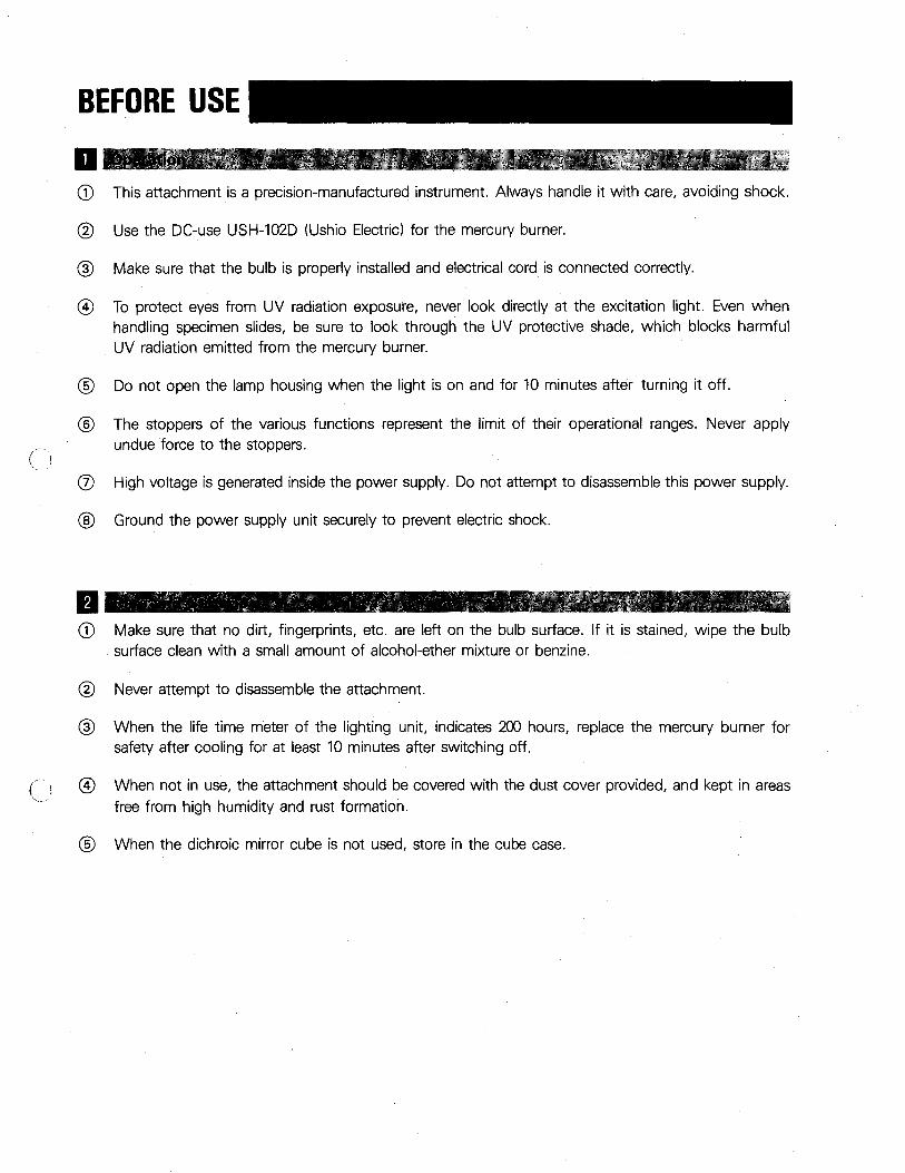
BEFORE USE
aCD This attachment is a precision-manufactured instrument. Always handle it with care, avoiding shock.
@ Use the DC-use USH-102D (Ushio Electric) for the mercury burner.
@ Make sure that the bulb is properly installed and electrical cord is connected correctly.
@ To protect eyes from UV radiation exposure, never look directly at the excitation light. Even whenhandling specimen slides, be sure to look through the UV protective shade, which blocks harmfulUV radiation emitted from the mercury burner.
® Do not open the lamp housing when the light is on and for 10 minutes after turning it off.
® The stoppers of the various functions represent the limit of their operational ranges. Never applyundue force to the stoppers.
(J) High voltage is generated inside the power supply. Do not attempt to disassemble this power supply.
® Ground the power supply unit securely to prevent electric shock.
fJCD Make sure that no dirt, fingerprints, etc. are left on the bulb surface. If it is stained, wipe the bulb
surface clean with a small amount of alcohol-ether mixture or benzine.
@ Never attempt to disassemble the attachment.
@
(, @
'\..~- .,'
®
When the life time meter of the lighting unit, indicates 200 hours, replace the mercury burner forsafety after cooling for at least 10 minutes after switching off.
When not in use, the attachment should be covered with the dust cover provided, and kept in areasfree from high humidity and rust formation.
When the dichroic mirror cube is not used, store in the cube case.
CONTENTS
1 ABSTRACT
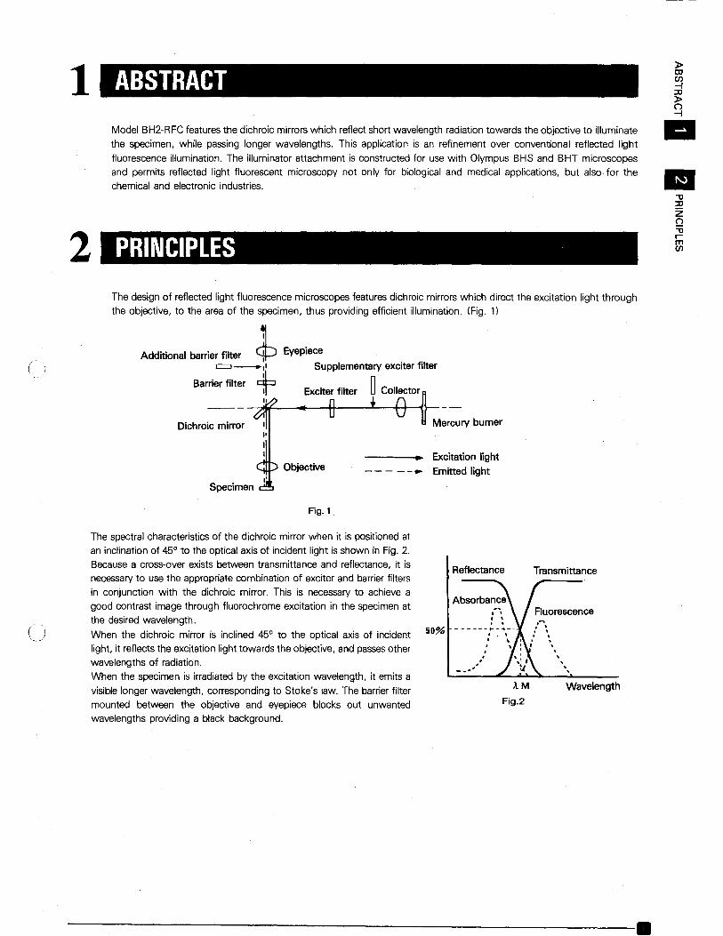
Model BH2-RFC features the dichroic mirrors which reflect short wavelength radiation towards the objective to illuminate
the specimen, while passing longer wavelengths. This application is an refinement over conventional reflected light
fluorescence illumination. The illuminator attachment is constructed for use with Olympus BHS and BHT microscopes
and permits reflected light fluorescent microscopy not only for biological and medical applications, but also for the
chemical and electronic industries.
»tDen-f::tJ»~••
2 PRINCIPLES
-0~zQ-0rmen
Mercury burner
---__t.... Excitation light
- - - - -.. Emitted light
Eyepiece
Supplementary exciter filter
~ Collector~
Specimen
Dichroic mirror
The design of reflected light fluorescence microscopes features dichroic mirrors which direct the excitation light through
the objective, to the area of the specimen, thus providing efficient illumination. (Fig. 1)
Additionel barrier .Ito, ~=-11
Barrier filter +I.
Fig. 1
The spectral characteristics of the dichroic mirror when it is positioned at
an inclination of 45° to the optical axis of incident light is shown in Fig. 2.
Because a cross-over exists between transmittance and reflectance, it is
necessaryto use the appropriate combination of exciter and barrier filters
in conjunction with the dichroic mirror. This is necessary to achieve a
good contrast image through fluorochrome excitation in the specimen at
the desired wavelength.
When the dichroic mirror is inclined 45° to the optical axis of incident
light, it reflects the excitation light towards the objective, and passesother
wavelengths of radiation.
When the specimen is irradiated by the excitation wavelength, it emits a
visible longer wavelength, corresponding to Stoke's law. The barrier filter
mounted between the objective and eyepiece blocks out unwantedwavelengths providing a black background.
50%
Reflectance Transmittance
Fluorescence
...A M Wavelength
Fig.2
------------------------.
iii
3 STANDARD EOUIPMENT
IZw~Q..
Sdwoa:::-coz~en
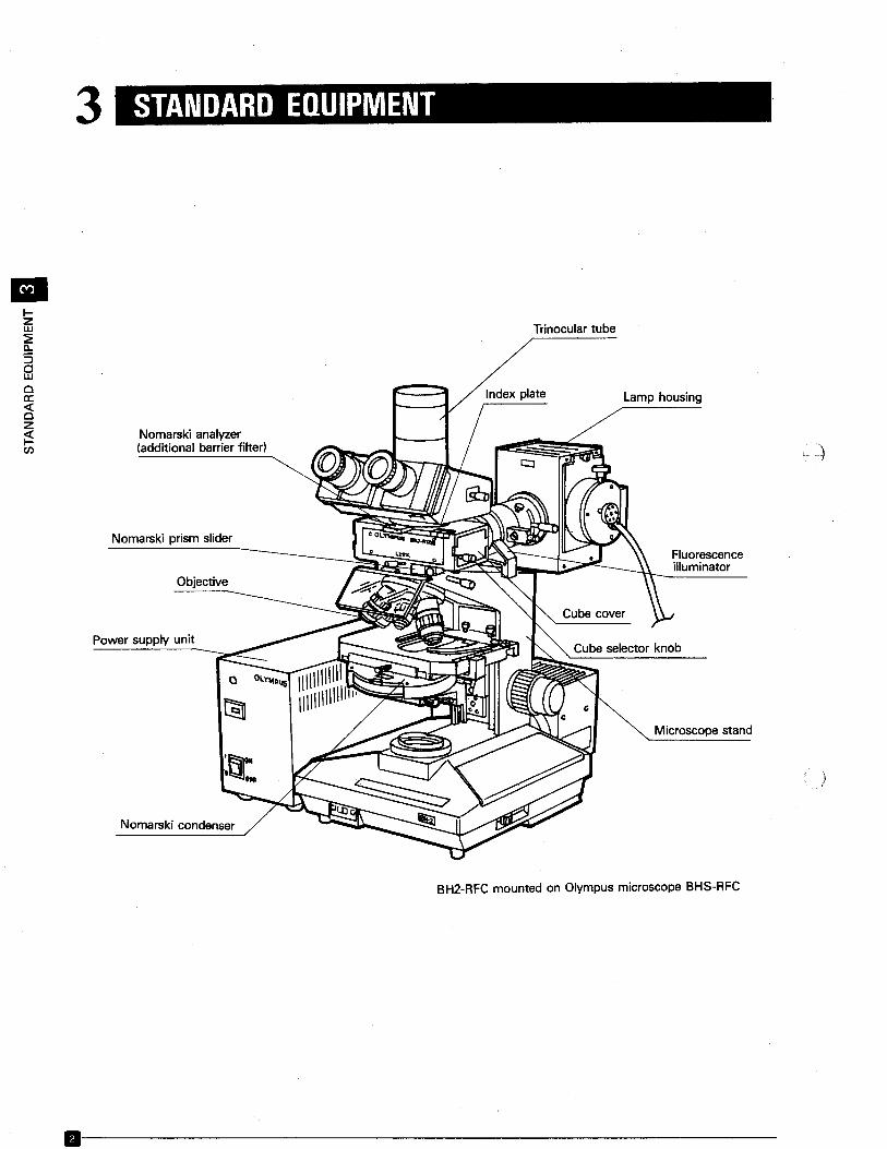
Nomarski analyzer(additional barrier filter)
Nomarski prism slider
Objective
Power supply unit
Nomarski condenser
Trinocular tube
Lamp housing
Fluorescenceilluminator
Microscope stand
BH2-RFC mounted on Olympus microscope BHS-RFC
)
)
11------------------------
( .1'",--
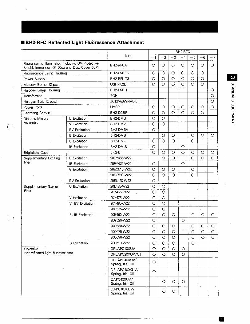
• BH2-RFC Reflected Light Fluorescence Attachment
BH2-RFCItem -1 -2 -3 -4 -5 -6 -7
Fluorescence Illuminator, including UV Protective BH2-RFCA 0 0 0 0 0 0 0Shield, Immersion Oil 50cc and Dust Cover B071
Fluorescence Lamp Hausing BH2-LSRF-2 0 0 0 0 0 0
Power Supply BH2-RFL-T3 0 0 0 0 0 0
Mercury Burner (2 pcs.) USH-l02D 0 0 0 0 0 0
Halogen Lamp Housing BH2-LSRH 0
Transformer TGH 0
Halogen Bulb (2 pcs.) JC12V50WHAL-L 0
Power Cord UYCP 0 0 0 0 0 0 0
Centering Screen BH2-SGRF 0 0 0 0 0 0
Dichroic Mirrors U Excitation BH2-DMU 0 0Assembly V Excitation BH2-DMV 0 0
BV Excitation BH2-DMBV 0
B Excitation BH2-DMB 0 0 0 0 0
G Excitation BH2-DMG 0 0 0 0
IB Excitation BH2-DMIB 0 0
Brightfield Cube BH2-BF 0 0 0 0 0 0 0
Supplementary Exciting B Excitation 20EY455-W22 0 0 0 0 0filter IB Excitation 20EY475-W22 0 0
G Excitation 2OE0515-W22 0 0 0 020E0530-W22 0 0 0 0
BV Excitation 20EL420-W22 0
Supplementary Barrier U Excitation 20L435-W22 0 0Filter 2OY455-W22 0 0
V Excitation 20Y475-W22 0 0V, BV Excitation 20Y495-W22 0 0
200515-W22 0 0B, IB Excitation 2OB460-W22 0 0 0 0 0 0
2OG520-W22 0 020053D-W22 0 0 0 0 0 020057D-W22 0 0 0 0 0 0200590-W22 0 0 0 0 0 0
G Excitation 20R61D-W22 0 0 0 0Objective DPLAP010XUV 0 0 0 0(for reflected light fluorescence) DPLAP020XUV/Oil 0 0 0 0
DPLAP040XUV/0Spring, Iris, Oil
DPLAP0100XUV/0Spring, Iris, Oil
DAP040XUV/0 0 0Spring, Iris, Oil
DAP0100XUV/0 0Spring, Iris, Oil
------------------------B
IIICIl
~zc}>::0Cmps"~mZ-I
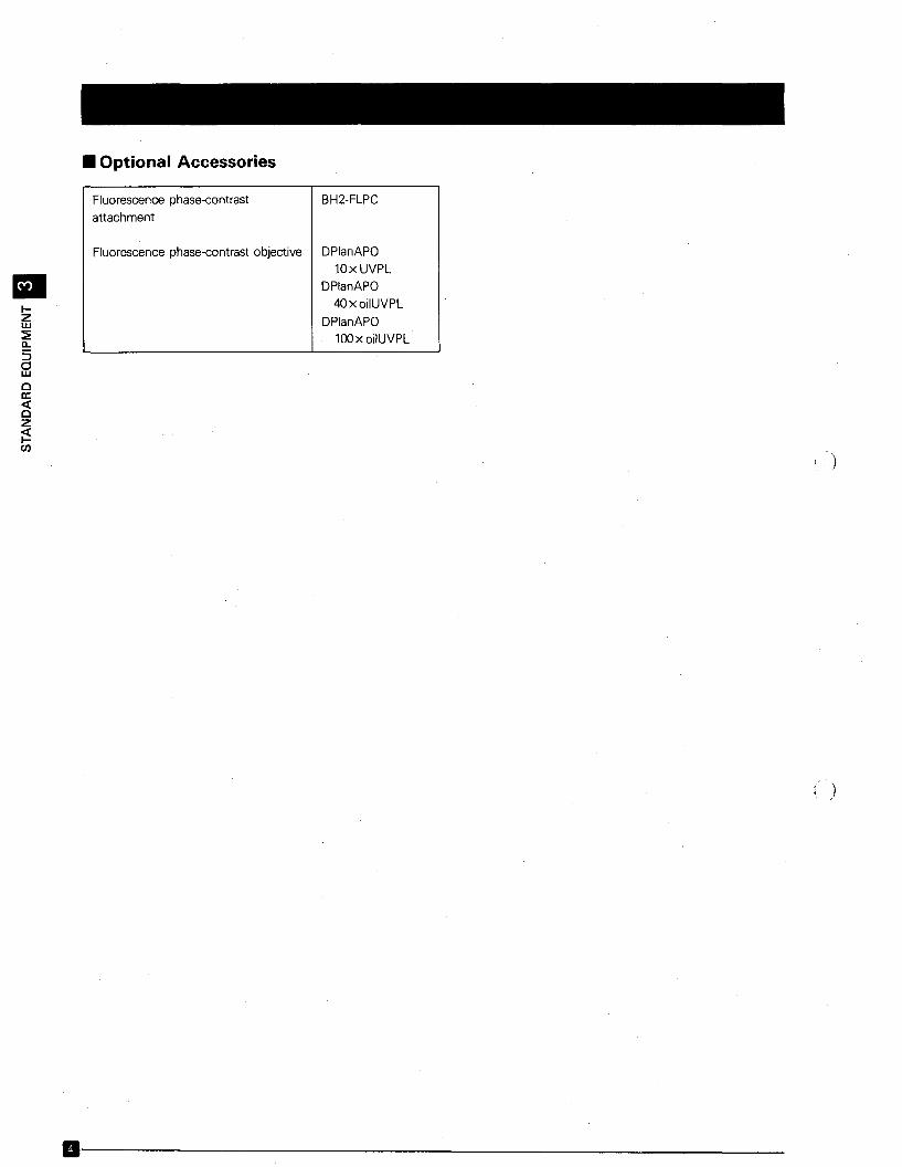
• Optional Accessories
Fluorescence phase-contrast
attachment
BH2-FLPC
IIIZw~c,
5dwoa:«oz~rn
Fluorescence phase-contrast objective DPlanAPO10xUVPL
DPlanAPO
4OxoilUVPL
DPlanAPO100x oilUVPL
B-------------------------
)
)
(
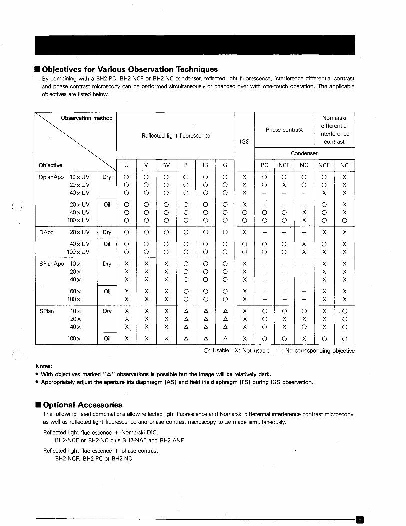
• Objectives for Various Observation TechniquesBy combining with a BH2-PC, BH2-NCF or BH2-NC condenser, reflected light fluorescence, interference differential contrast
and phase contrast microscopy can be performed simultaneously or changed over with one-touch operation. The applicableobjectives are listed below.
Observation method Nomarski
Phase contrastdifferential
Reflected light fluorescence interference
IGS contrast
Condenser
Objective U V BV B IB G PC NCF NC NCF NC
DplanApo lOxUV Dry' 0 0 0 0 0 0 X 0 0 0 0 X20xUV 0 0 0 0 0 0 X 0 X 0 0 X40xUV 0 0 0 0 0 0 X - - - X X
20xUV Oil 0 0 0 0 0 0 X - - - 0 X40xUV 0 0 0 0 0 0 0 0 0 X 0 X
100x UV 0 0 0 0 0 0 0 0 0 X 0 0
DApo 20xUV Dry 0 0 0 0 0 0 X - - - X X
40xUV Oil 0 0 0 0 0 0 0 0 0 X 0 X100x UV 0 0 0 0 0 0 0 0 0 X X X
SPlanApo lOx Dry X X X 0 0 0 X - - - X X20x X X X 0 0 0 X - - - X X40x X X X 0 0 0 X - - - X X
60x Oil X X X 0 0 0 X - - - X X100x X X X 0 0 0 X - - - X X
SPlan lOx Dry X X X t::. t::. t::. X 0 0 0 X ·020x X X X t::. t::. t::. X 0 X X X 040x X X X t::. t::. t::. X 0 X 0 X 0
100x Oil X X X t::. t::. t::. X 0 0 X 0 0
0: Usable X: Not usable -: No corresponding objective
Notes:
• With objectives marked U t::." observations is possible but the image will be relatively dark.
• Appropriately adjust the aperture iris diaphragm (AS) and field iris diaphragm (FS) during IGS observation .
• Optional AccessoriesThe following listed combinations allow reflected light fluorescenceand Nomarski differential interference contrast microscopy,as well as reflected light fluorescence and phase contrast microscopy to be made simultaneously.
Reflected light fluorescence + Nomarski DIC:BH2-NCF or BH2-NC plus BH2-NAF and BH2-ANF
Reflected light fluorescence + phase contrast:BH2-NCF, BH2-PC or BH2-NC
----------------.,.---------------B
•IZw~a..
§oa:«oz~C/)
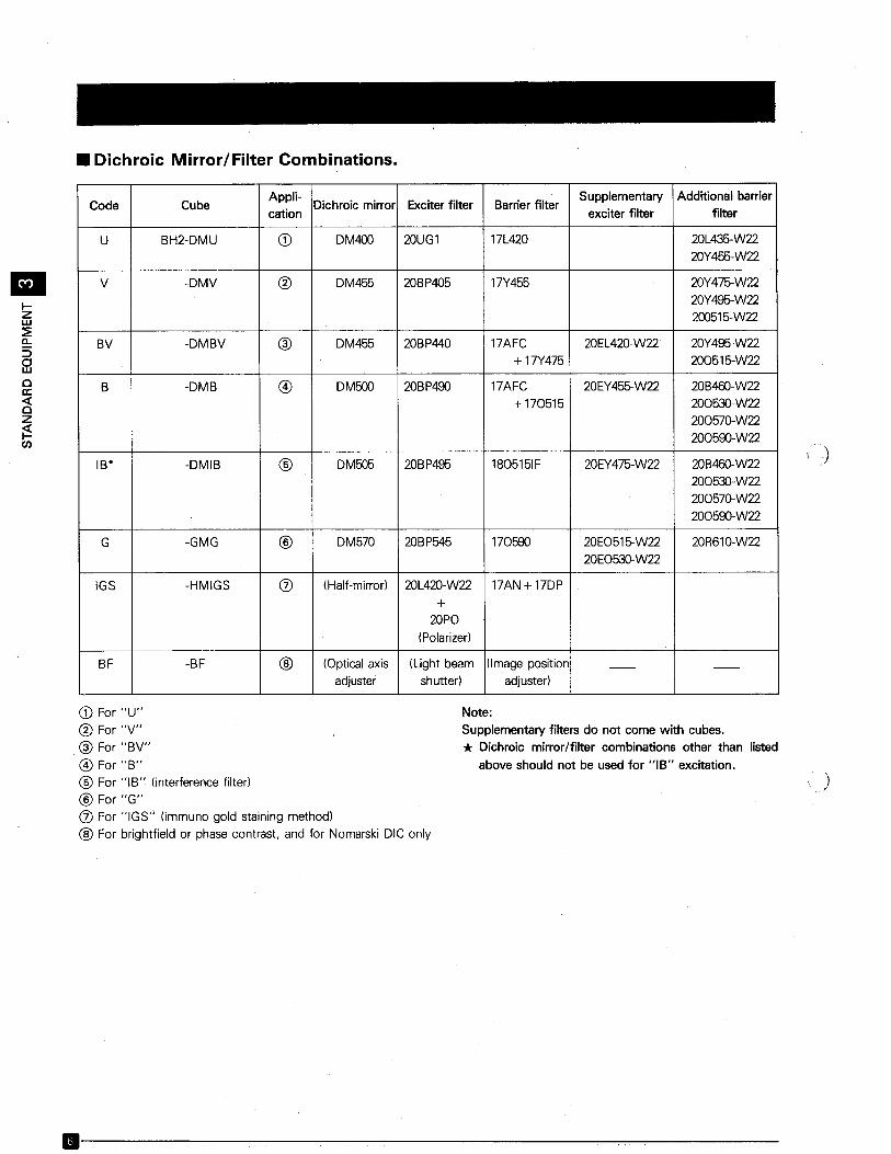
• Dichroic Mirror/Filter Combinations.
Appli-Dichroic mirror Exciter filter Barrier filter
Supplementary Additional barrierCode Cube
cation exciter filter filter
U BH2-DMU CD DM400 20UG1 17L420 20L435-W22
20Y455-W22
V -DMV ® DM455 20BP405 17Y455 20Y475-W22
20Y495-W22
200515-W22
BV -DMBV @ DM455 20BP440 17AFC 20EL420-W22 20Y495-W22
+ 17Y475 200515-W22
B -DMB @ DM500 20BP490 17AFC 20EY455-W22 20B460-W22
+ 170515 200530-W22200570-W22
200590-W22
IB* -DMIB ® DM505 20BP495 1805151F 20EY475-W22 20B460-W22
200530-W22
20057G-W22
200590-W22
G -GMG ® DM570 20BP545 170590 20E0515-W22 20R610-W22
20E0530-W22
IGS -HMIGS (J) (Half-mirror) 20L42G-W22 17AN +17DP
+20PO
(Polarizer)
BF -BF ® (Optical axis (Light beam (Image position -- --adjuster shutter) adjuster)
)
CD For "U"
® For "V"
@ For "BV"
@ For "B"® For "IB" (interference filter)
® For "G"(J) For "IGS" Iirnrnuno gold staining method)
® For brightfield or phase contrast, and for Nomarski DIC only
Note:
Supplementary filters do not come with cubes.
* Dichroic mirror/filter combinations other than listed
above should not be used for "IB" excitation.
)
11----------------------------
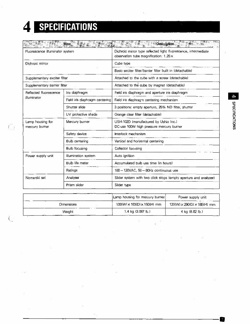
4 SPECIFICATIONS
Fluorescence illuminator system
Dichroic mirror
Dichroic mirror type reflected light fluorescence, intermediateobservation tube magnification: 1.25x
Cube type
Basic exciter filter/barrier filter built in (detachable)
Field iris diaphragm centering Field iris diaphragm centering mechanism
Supplementary barrier filter
Supplementary exciter filter
Reflected fluorescence
illuminator
Lamp housing for
mercury burner
Power supply unit
Nomarski set
Iris diaphragm
Shutter slide
UV protective shade
Mercury burner
Safety device
Bulb centering
Bulb focusing
Illumination system
Bulb life meter
Ratings
Analyser
Prism slider
Attached to the cube with a screw (detachable)
Attached to the cube by magnet (detachable)
Field iris diaphragm and aperture iris diaphragm
3 positions: empty aperture, 25% ND filter, shutter
Orange clear filter (detachable)
USH-102D (manufactured by Ushio lnc.)DC-use 100W high pressure mercury burner
Interlock mechanism
Vertical and horizontal centering
Collector focusing
Auto ignition
Accumulated bulb use time (in hours)
100-120VAC, 50-60Hz continuous use
Slider system with two click stops (empty aperture and analyzer)
Slider type
•en"tlmQ."n~ozen
(
Lamp housing for mercury burner Power supply unit
Dimensions 133(W)x 163(D)x 15O(H) mm 120(W)x 290(D)x 185(H) mm
Weight 1.4 kg (3.087 lb.) 4 kg (8.82 lb.)
---------------------------,....-.
II(J)zo~oiI:(Jwa..(J)
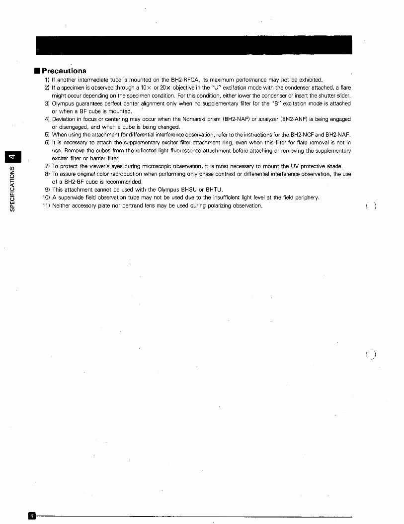
• Precautions1) If another intermediate tube is mounted on the BH2-RFCA, its maximum performance may not be exhibited.2) If a specimen is observed through a 10x or 20x objective in the "U" excitation mode with the condenser attached, a flare
might occur depending on the specimen condition. For this condition, either lower the condenser or insert the shutter slider.3) Olympus guarantees perfect center alignment only when no supplementary filter for the "B" excitation mode is attached
or when a BF cube is mounted.4) Deviation in focus or centering may occur when the Nomarski prism (BH2-NAF) or analyzer (BH2-ANF) is being engaged
or disengaged, and when a cube is being changed.5) When using the attachment for differential interference observation, refer to the instructions for the BH2-NCF and BH2-NAF.6) It is necessary to attach the supplementary exciter filter attachment ring, even when this filter for flare removal is not in
use. Remove the cubes from the reflected light fluorescence attachment before attaching or removing the supplementaryexciter filter or barrier filter.
7) To protect the viewer's eyes during microscopic observation, it is most necessary to mount the UV protective shade.8) To assure original color reproduction when performing only phase contrast or differential interference observation, the use
of a BH2-BF cube is recommended.9) This attachment cannot be used with the Olympus BHSU or BHTU.
10) A superwide field observation tube may not be used due to the insufficient light level at the field periphery.
11) Neither accessory plate nor bertrand lens may be used during'polarizing observation.
.---------------------~---
)
)
5 NOMENCLATURE
Prism slider(BH2-NAFI
Observation tube ,clamping screw
(
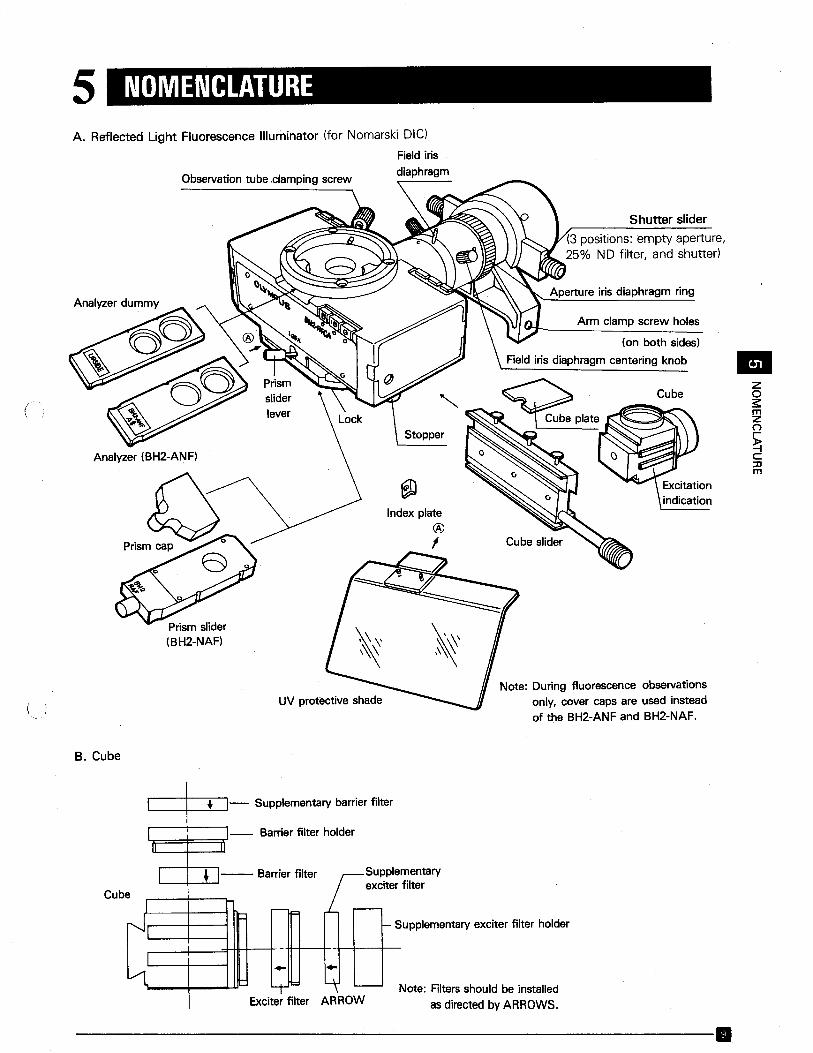
A. Reflected Light Fluorescence Illuminator (for Nomarski OIC)
Field irisdiaphragm
Shutter slider
(3 positions: empty aperture,25% NO filter, and shutter)
Aperture iris diaphragm ring
Arm clamp screw holes
(on both sides)
Field iris diaphragm centering knob
Cube
Note: During fluorescence observationsonly, cover caps are used insteadof the BH2-ANF and BH2-NAF.
•zo~mZ(")
~C::0m
B. Cube
upplementary exciter filter holder
Note: Filters should be installedas directed by ARROWS.
~- Supplementary barrier filter
~-- Barrier filter holder
• Barrier filter Supplementaryfilter
--I
excitere
"'-F r--
r--.' "-S.."
- -
VL - ..b: ~ '---
Exciter filter ARROW
Cub
--------------'--------------.
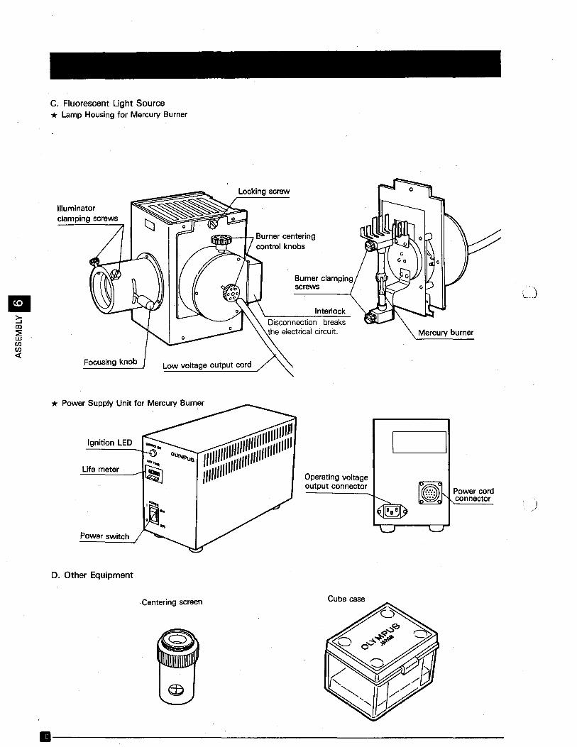
c. Fluorescent Light Source* Lamp Housing for Mercury Burner
~IX!~wenen«
Illuminatorclamping screws
Focusing knob
Locking screw
Burner clampingscrews
InterlockDisconnection breaksthe electrical circuit.
Low voltage output cord
* Power Supply Unit for Mercury Burner
Ignition LED
Life meter
Power switch
D. Other Equipment
·I"I"I"~11I11I"1"111111111:11/11111111
",,"If'"
.Centering screen
Operating voltageoutput connector
Cube case
Power cordconnector
)
D--------------------------
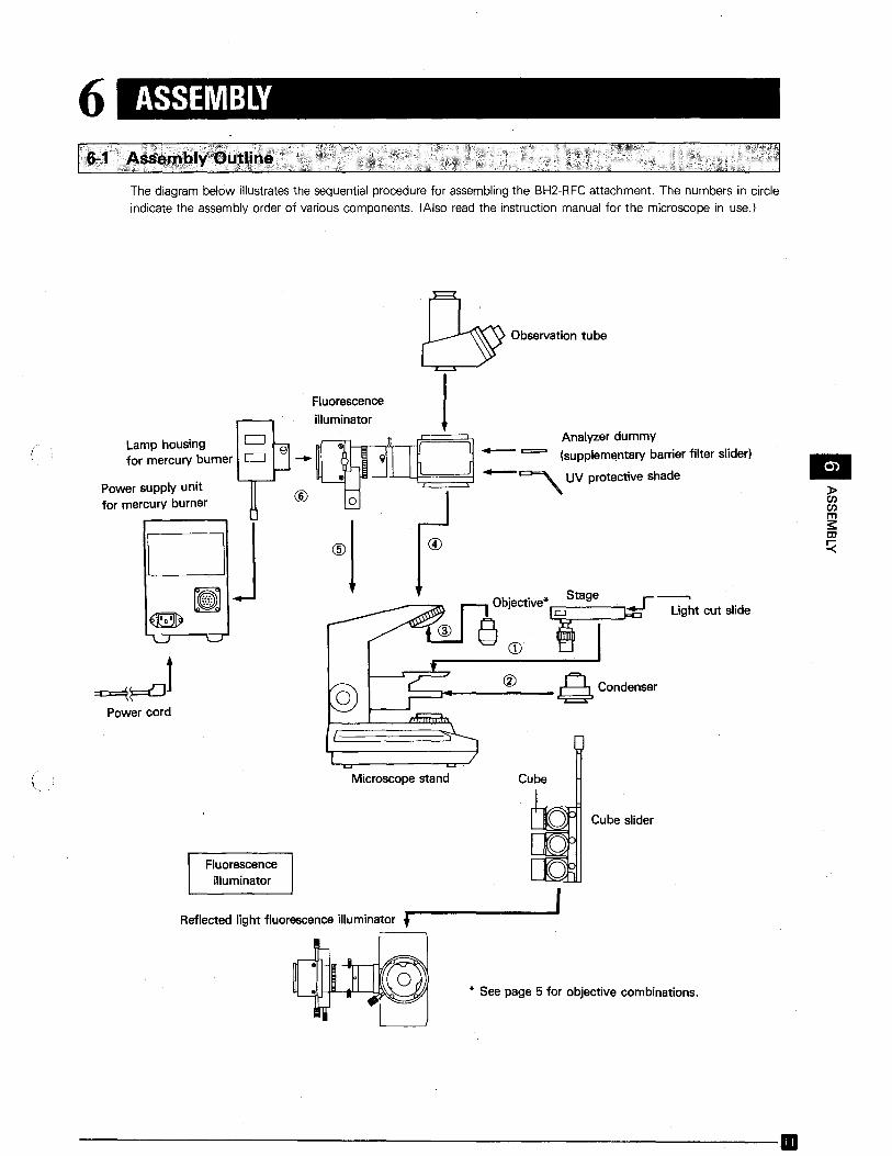
6 ASSEMBLY
The diagram below illustrates the sequential procedure for assembling the BH2-RFC attachment. The numbers in circle
indicate the assembly order of various components. (Also read the instruction manual for the microscope in use.)
•):>enenms::to
~
CD
®
~ Observation tube
J
==J4-------,S. Condenser
Fluorescenceilluminator
o ~'; Analyzer dummyLamp housing 8. ~for mercury burner c=J -- 9 n- === (supplementary barrier filter slider)
® iii 0 ~~~~~ -~ UV protective shade
@!
Power cord
Power supply unitfor mercury burner
(
Microscope stand Cube
Fluorescenceilluminator
Reflected light fluorescence illuminator t
Cube slider
* See page 5 for objective combinations.
-------------------------11
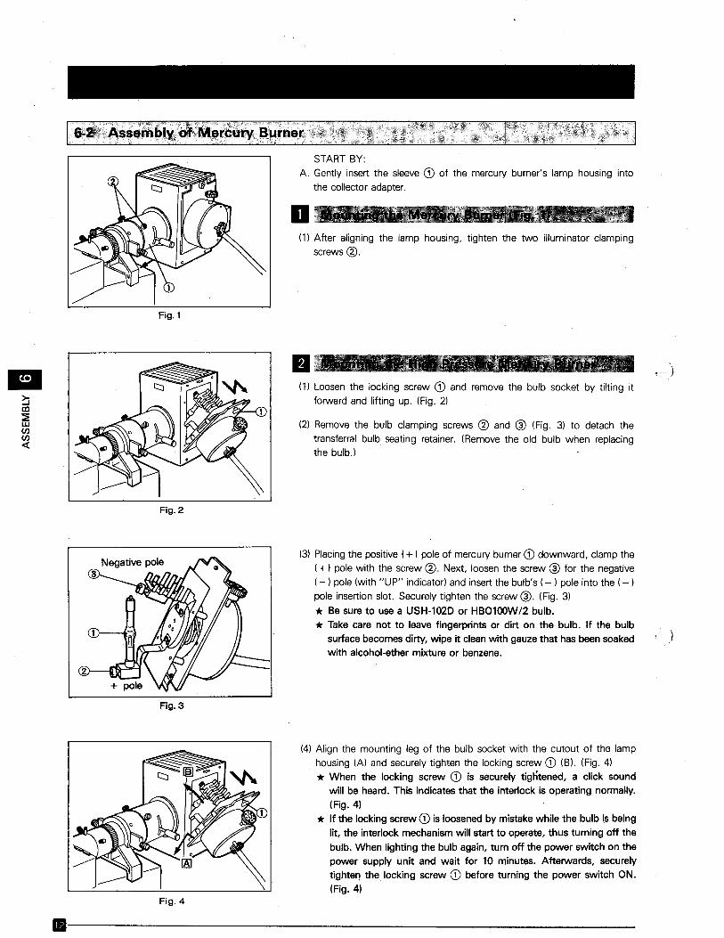
•~al~Wenen«
START BY:A. Gently insert the sleeve CD of the mercury burner's lamp housing into
the collector adapter.
(1) After aligning the lamp housing, tighten the two illuminator clampingscrews@.
Fig. 1
II(1) Loosen the locking screw CD and remove the bulb socket by tilting it
forward and lifting up. (Fig. 2)
(2) Remove the bulb clamping screws @ and @ (Fig. 3) to detach thetransferral bulb seating retainer. (Remove the old bulb when replacingthe bulb.)
Fig. 2
(3) Placing the positive (+) pole of mercury burner CD downward, clamp the(-r) pole with the screw @. Next, loosen the screw @ for the negative(-) pole (with "UP" indicator) and insert the bulb's (- ) pole into the (-)pole insertion slot. Securely tighten the screw @. (Fig. 3)
* Be sure to use a USH-102D or HB0100W/2 bulb.* Take care not to leave fingerprints or dirt on the bulb. If the bulb
surface becomes dirty, wipe it clean with gauze that has been soaked )with alcohol-ether mixture or benzene.
Fig. 3
(4) Align the mounting leg of the bulb socket with the cutout of the lamphousing (A) and securely tighten the locking screw CD (B). (Fig. 4)* When the locking screw CD is securely tightened, a click sound
will be heard. This indicates that the interlock is operating normally.(Fig. 4)
* If the locking screw CD is loosened by mistake while the bulb is beinglit, the interlock mechanism will start to operate, thus turning off the
bulb. When lighting the bulb again, turn off the power switch on thepower supply unit and wait for 10 minutes. Afterwards, securelytiqhten the locking screw CD before turning the power switch ON.(Fig. 4)
Fig.4
B--------------------------
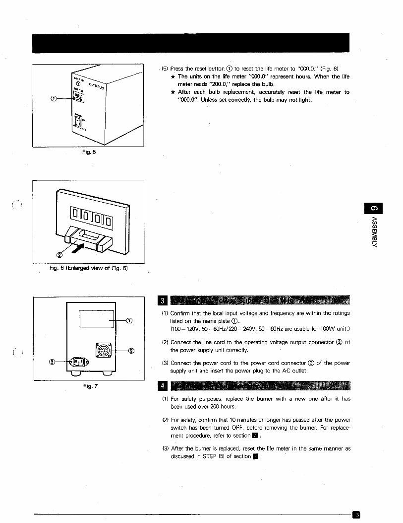
(5) Press the reset button CD to reset the life meter to "000.0." (Fig. 6)
* The units on the life meter "000.0" represent hours. When the lifemeter reads "200.0," replace the bulb.
* After each bulb replacement, accurately reset the life meter to"000.0". Unless set correctly, the bulb may not light.
Fig. 5
Fig. 6 (Enlarged view of Fig. 5)
lEI»enenms:to!:(
..Fig. 7
II(1) Confirm that the local input voltage and frequency are within the ratings
listed on the name plate CD.(loo-120V, 5O-60Hz/220-240V, 50-60Hz are usable for 100W unit.)
(2) Connect the line cord to the operating voltage output connector @ ofthe power supply unit correctly.
(3) Connect the power cord to the power cord connector ® of the powersupply unit and insert the power plug to the AC outlet .
(1) For safety purposes, replace the burner with a new one after it has
been used over 200 hours.
(2) For safety, confirm that 10 minutes or longer has passed after the power
switch has been turned OFF, before removing the burner. For replacement procedure, refer to section •.
(3) After the burner is replaced, reset the life meter in the same manner as
discussed in STEP (5) of section •.
---------------------'------~----.
•~al~W(J)(J)
«
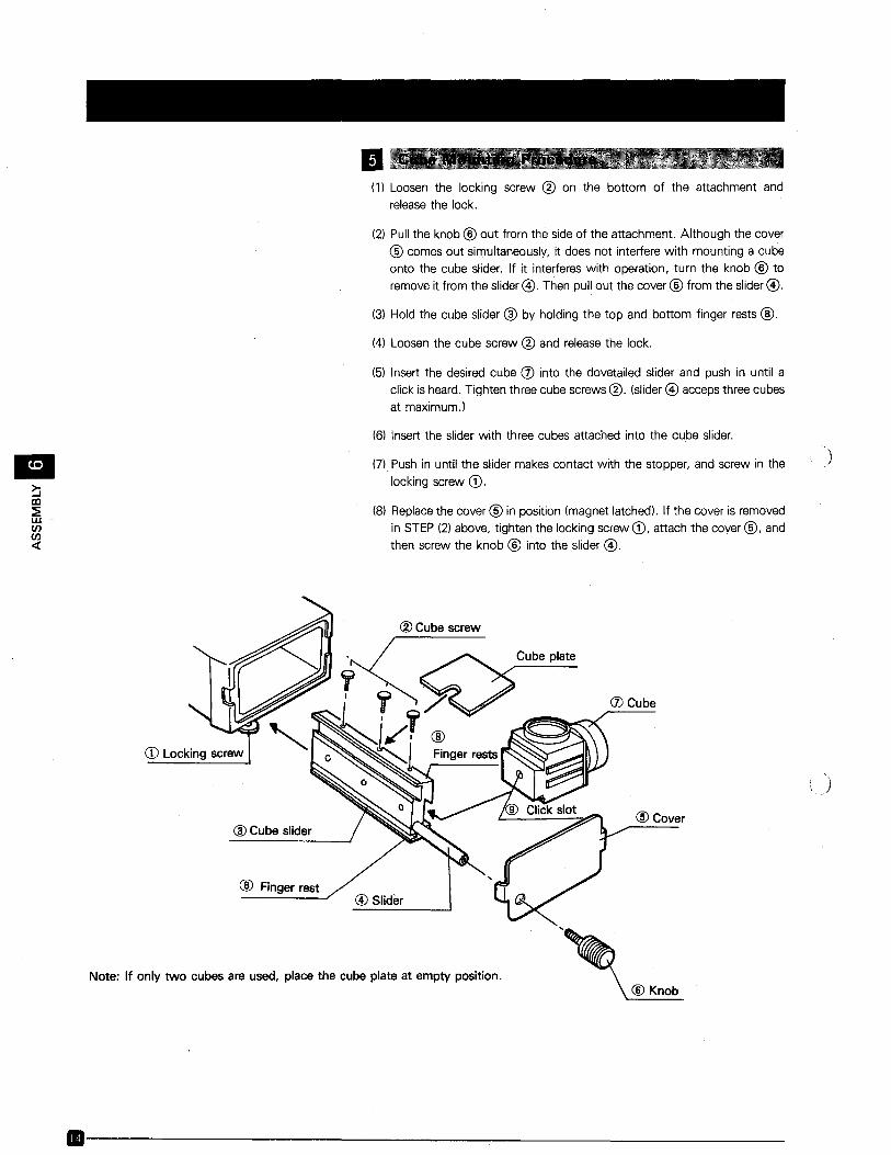
(1) Loosen the locking screw ® on the bottom of the attachment and
release the lock.
(21 Pull the knob ® out from the side of the attachment. Although the cover
® comes out simultaneously, it does not interfere with mounting a cubeonto the cube slider. If it interferes with operation, turn the knob ® to
remove it from the slider@. Then pull out the cover ® from the slider@.
(31 Hold the cube slider ® by holding the top and bottom finger rests @.
(4) Loosen the cube screw ® and release the lock.
(61 Insert the desired cube (f) into the dovetailed slider and push in until aclick is heard. Tighten three cube screws ®. (slider@ acceps three cubesat rnaxirnurn.)
(6) Insert the slider with three cubes attached into the cube slider.
(7) Push in until the slider makes contact with the stopper, and screw in the
locking screw CD.
(81 Replace the cover ® in position (magnet latched). If the cover is removedin STEP (2) above, tighten the locking screw CD, attach the cover ®, andthen screw the knob ® into the slider @.
®Cube screw
Note: If only two cubes are used, place the cube plate at empty position.
CD Locking screw
@Cubeslider
@ Finger rest@Slider
Cube plate
(J) Cube
@Cover
®Knob
)
·-------------------:------------
Dichroic mirror(
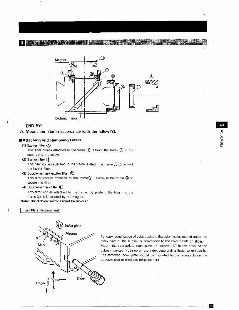
END BY:A. Mount the filter in accordance with the following. •»enen
ms:OJ
~
~I
Magnet
• Attaching and Removing Filters(1) Exciter filter @
This filter comes attached to the frame CD. Mount the frame CD to thecube using the screw.
(2) Barrier filter @This filter comes attached to the frame. Detach the frame @ to removethe barrier filter.
(3) Supplementary exciter filter ©This filter comes attached to the frame ®. Screw in the frame @ tosecure the filter.
(4) Supplementary filter @This filter comes attached to the frame. By pushing the filter into theframe @, it is secured by the magnet.
Note: The dichroic mirror cannot be replaced.
( !Index Plate Replacement I
For easy identification of cube position, the color marks located under theindex plate of the illuminator correspond to the color bands on slider.Mount the appropriate index plate on section "A" in the order of the
cubes mounted. Push up on the index plate with a finger to remove it.The removed index plate should be mounted to the receptacle on theopposite side to eliminate misplacement.
---------------------------.
7 OPERATION
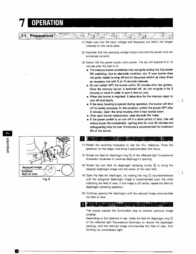
(1) Make sure that the input voltage and frequency are within the ranges
indicated on the name plate.
(2) Ascertain that the operating voltage output cord and the power cord are
connected correctly.
•zo~a:wa..o
Fig.8
(3) Switch ON the power supply unit's power. The arc will stabilize 5 or 10
minutes after the light is lit.* The mercury burner sometimes may not ignite during the first power
ON switching, due to electrode condition, etc. If your burner doesnot ignite, repeat turning off and on the power switch as many times
as necessary but with 5 to 10 seconds intervals.* Do not switch OFF the burner within 15 minutes after the ignition.
Once the mercury burner is switched off, do not re-ignite it for 3minutes or more in order to give it time to cool.
* When the burner is reignited, it takes time for the mercury vapor tocool off and liquify.
* If the lamp housing is opened during operation, the burner will shutoff for safety purposes. In this situation, switch the power OFF after3 minutes. Open the lamp housing after it has cooled down.
* After each burner replacement, reset the bulb life meter.* If the power switch is on and off in a short period of time, this will
reduce buner life considerably. Igniting time for over 30 minutes andextinguishing time for over 10 minutes is recommended for maximum
life of the burner.
D(1) Rotate the revolving nosepiece to use the lOx objective. Place the
specimen on the stage, and bring it approximately into focus.
(2) Rotate the field iris diaphragm ring CD of the reflected light fluorescenceilluminator clockwise to minimize diaphragm's opening.
(3) Rotate the two field iris diaphragm centering knobs ® to bring thereduced diaphragm image into the center of the view field.
(4) Open the field iris diaphragm, by rotating the ring CD counterclockwiseuntil the polygonal diaphragm image is superimposed upon the circle
indicating the field of view. If the image is off center, repeat the field irisdiaphragm centering operation.
(5) Continue opening the diaphragm until the reduced image circumscribesthe field of view.
)
IIThis proces adjusts the illumination area to achieve optimum imagecontrast.Depending on the objective in use, rotate the field iris diaphragm ring CDof the reflected light fluorescence illuminator to reduce the diaphragmopening, until the reduced image circumscribes the field of view, thusshutting out unnecessary light .
.------------------_....:......-_---
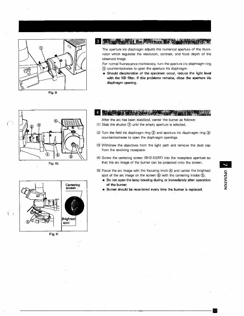
IIThe aperture iris diaphragm adjusts the numerical aperture of the illuminator which regulates the resolution, contrast, and focal depth of the
observed image.
For normal fluorescence microscopy, turn the aperture iris diaphragm ringCD counterclockwise to open the aperture iris diaphragm.* Should discoloration of the specimen occur, reduce the light level
with the ND filter. If this problems remains, close the aperture irisdiaphragm opening.
Fig. 9
o'1Jm:::c~oz
•(5) Focus the arc image with the focusing knob @) and center the brightestspot of the arc image on the screen ® with the centering knobs @.* Do not open the lamp housing during or immediately after operation
of the burner.* Burner should be recentered every time the burner is replaced.
(4) Screw the centering screen (BH2-SGRF) into the nosepiece aperture sothat the arc image of the burner can be projected onto the screen.
After the arc has been stabilized, center the burner as follows:(1) Slide the shutter CD until the empty aperture is selected.
(3) Withdraw the objectives from the light path and remove the dust capfrom the revolving nosepiece.
(2) Turn the field iris diaphragm ring ® and aperture iris diaphragm ring @counterclockwise to· open the diaphragm openings.
..
Centeringscreen·
Fig. 10
(
(
Fig. 11
-----------------------------.
•zo~a:wCO
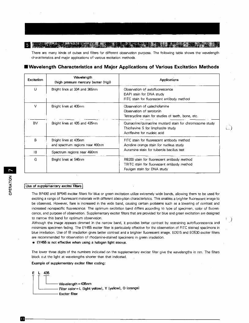
There are many kinds of cubes and filters for different observation purpose. The following table shows the wavelengthcharacteristics and major applications of various excitation methods.
• Wavelength Characteristics and Major Applications of Various Excitation Methods
ExcitationWavelength
Applications(high pressure mercury burner (Hg))
U Bright lines at 334 and 365nm Observation of autofluorescenceDAPI stain for DNA studyFITC stain for fluorescent antibody method
V Bright lines at 405nm Observation of catecholamineObservation of serotonin
Tetracycline stain for studies of teeth, bone, etc.
BV Bright lines at 405 and 435nm Quinacrine/quinacrine mustard stain for chromosome study
Thiofravine S for limphocite studyAcriflavine for nucleic acid
B Bright lines at 435nm FITC stain for fluorescent antibody methodand spectrum regions near 490nm Acridine orange stain for nucleus study
IB Spectrum regions near 490nmAuramine stain for tubercle bacillus test
G Bright lines at 546nm RB200 stain for fluorescent antibody methodTRITC stain for fluorescerit antibody method
Feulgen stain for DNA study
IUse of supplementary exciter filters IThe BP490 and BP545exciter filters for blue or green excitation utilize extremely wide bands, allowing them to be used forexciting a range of fluorescent materials with different absorption characteristics. This enables a brighter fluorescent image to
be observed. However, flare is increased in the wide band, causing certain problems such as a lowering of contrast and
increased nonspecific fluorescence. The optimum excitation band differs according to type of specimen, color of fluorescence, and purpose of observation. Supplementary exciter filters that are provided for blue and green excitation are designedto narrow this band for optimum observation.Although the image appears dimmed in the narrow band, it provides better contrast by restraining autofluorescence andminimizes specimen fading. The EY455 exciter filter is particularly effective for the observation of FITC-stained specimens in
blue irradiation. Use of IB irradiation gives better contrast and a brighter fluorescent image. E0515 and E0530 exciter filtersare recommended for observation of rhodamine-stained specimens in green irradiation.
* EY455 is not effective when using a halogen light source.
The lower three digits of the numbers indicated on the supplementary exciter filter give the wavelengths in nm. The filtersblock out the light at wavelengths shorter than that indicated.
Example of supplementary exciter filter coding:
E L 435IIL_n~~435nmFilter color = L (light yellow), Y (yellow), 0 (orange)
Exciter filter
.---------------------------
)
(
(
IUse of supplementary barrier filters IIn addition to the barrier filter built into each cube, supplementary barrier filters can be fitted as required to block unnecessary
fluorescence and to control color.The lower three digits of the numbers indicated on the filters, excluding the B460 and G520, give respective wavelengths in
nm. These filters are used for transmitting light at wavelengths longer than that indicated, while blocking out those shorter
than the indication.
Example of supplementary barrier filter coding:
R 610
1T .W'''''''"gth~610"mFilter color = R (red), 0 (orange), Y (yellow), L (light yellow)
The supplementary barrier filters, B460 and G520, transfer light at the wavelength (nrn) close to that indicated by the lower
three-digit number on the filter designation. When combined with other filters, they can be used to control the color offluorescent image.The B460 blue filter is used to control the color of the fluorescent image in blue excitation which exhibits a strongly yellowishtone. However, the orange and red fluorescence remain dim.The G520 filter blocks out wavelengths longer than 540nm, namely orange and red fluorescence, allowing green light to passthrough.
In addition to controlling the color of the fluorescent image in the same way as the B460, the G520 filter also blocks or reducesfluorescent light other than FITC. This allows it to enhance contrast, and means that it shows only the FITC image of a doublestained image (e.g. FITC+ Rhodamine).
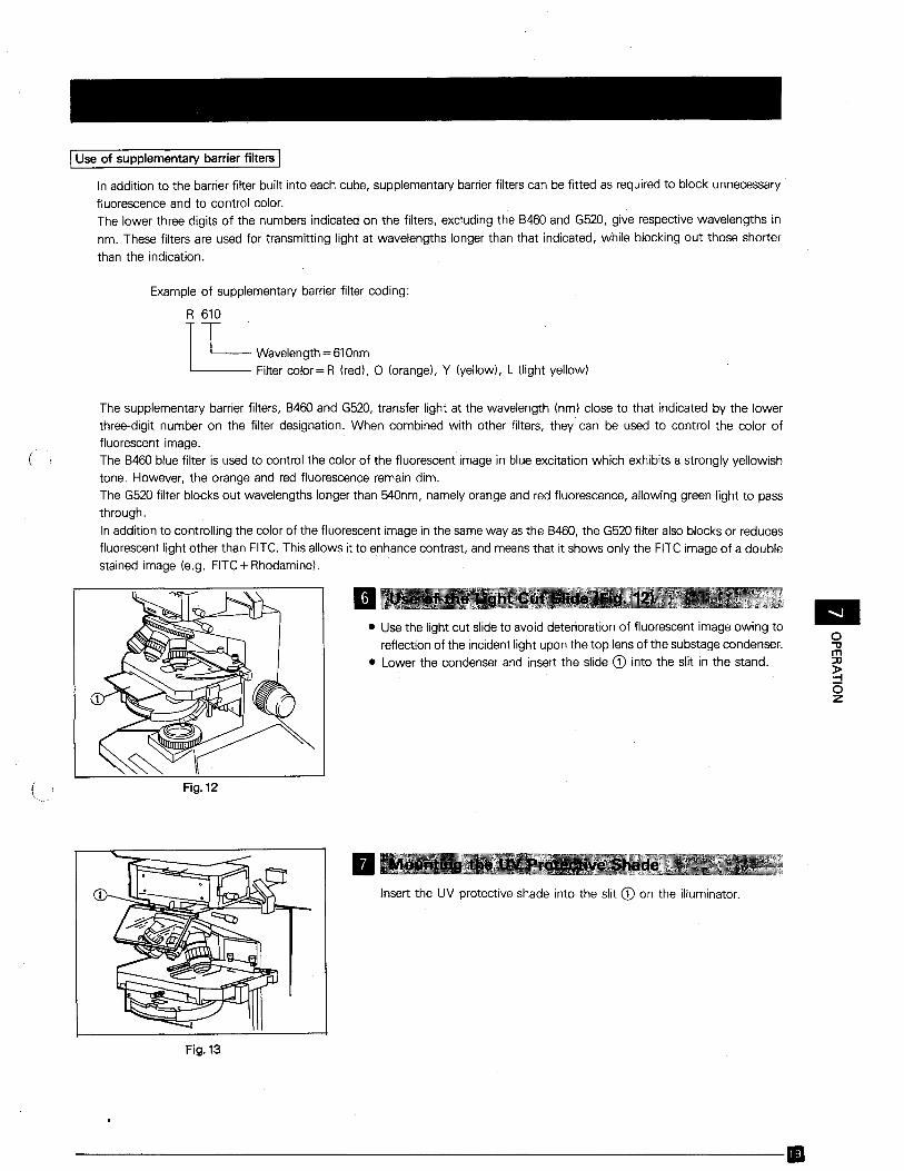
• Use the light cut slide to avoid deterioration of fluorescent image owing to
reflection of the incident light upon the top lens of the substage condenser.• Lower the condenser and insert the slide CD into the slit in the stand.
Fig. 12
o"m::x:J
~oz
Insert the UV protective shade into the slit CD on the illuminator.
Fig. 13
----------------------------B
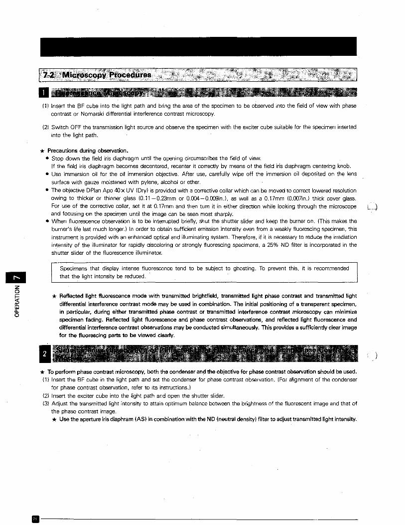
(1) Insert the BF cube into the light path and bring the area of the specimen to be observed into the field of view with phase
contrast or Nomarski differential interference contrast microscopy.
(2) Switch OFF the transmission light source and observe the specimen with the exciter cube suitable for the specimen inserted
into the light path.
* Precautions during observation.• Stop down the field iris diaphragm until the opening circumscribes the field of view.
If the field iris diaphragm becomes decentered, recenter it correctly by means of the field iris diaphragm centering knob.
• Use immersion oil for the oil immersion objective. After use, carefully wipe off the immersion oil deposited on the lens
surface with gauze moistened with pylene, alcohol or ether.
• The objective DPlan Apo 40x UV (Dry) is provided with a corrective collar which can be moved to correct lowered resolutionowing to thicker or thinner glass (0.11 -0.23mm or 0.004-0.009in.), as well as a 0.17mm (0.OD7in.) thick cover glass.
For use of the corrective collar, set it at 0.17mm and then turn it in either direction while looking through the microscopeand focusing on the specimen until the image can be seen most sharply.
• When fluorescence observation is to be interrupted briefly, shut the shutter slider and keep the burner on. (This makes theburner's life last much lonqer.) In order to obtain sufficient emission intensity even from a weakly fluorescing specimen, this
instrument is provided with an enhanced optical and illuminating system. Therefore, if it is necessary to reduce the irradiationintensity of the illuminator for rapidly discoloring or strongly fluorescing specimens, a 25% ND filter is incorporated in theshutter slider of the fluorescence illuminator.
Specimens that display intense fluorescence tend to be subject to ghosting. To prevent this, it is recommended
• that the light intensity be reduced.
zo~ * Reflected light fluorescence mode with transmitted brightfield, transmitted light phase contrast and transmitted light
ffi differential interference contrast mode may be used in combination. The initial positioning of a transparent specimen,g, in particular, during either transmitted phase contrast or transmitted interference contrast microscopy can minimize
specimen fading. Reflected light fluorescence and phase contrast observations, and reflected light fluorescence and
differential interference contrast observations may be conducted simultaneously. This provides a sufficiently clear imagefor the fluorescing parts to be viewed clearly.
I )* To perform phase contrast microscopy, both the condenser and the objective for phase contrast observation should be used.(1) Insert the BF cube in the light path and set the condenser for phase contrast observation. (For alignment of the condenser
for phase contrast observation, refer to its mstructions.l
(2) Insert the exciter cube into the light path and open the shutter slider.(3) Adjust the transmitted light intensity to attain optimum balance between the brightness of the fluorescent image and that of
the phase contrast image.* Use the aperture iris diaphram (AS) in combination with the ND (neutral density) filter to adjust transmitted light intensity.
.------------~--------------'---
(
I* The Nomarski attachment is required for Nomarski differential interference contrast microscopy.(1) Insert the SF cube into the light path and attach the polarizer and Nomarski prism. (Refer to the instructions provided for
the Nomarski attachment for the SH2-RFCl. The following steps are a repeat of those for the phase contrast microscopy,
starting at (2) of the previous page.
Note:CD A SF cube should be used when either phase contrast or Nomarski differential interference contract microscopy is per-
formed separately.@ When these two microscopy modes are combined for simultaneous observation, the fluorescence may appear dimmed.@) Specimens that display intense fluorescence tend to be subject to ghosting. To prevent this, it is recommended that the
light cut slide be used.
----------------------.
•o"tIm::tI
~oz
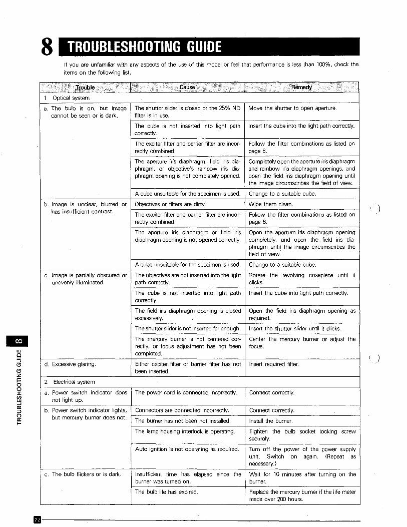
8 TROUBLESHOOTING GUIDEIf you are unfamiliar with any aspects of the use of this model or feel that performance is less than 100%, check theitems on the following list.
Optical system
lEIwo5(:J
(:Jzi=oo::c(J)w....Jco::>oa:I-
a. The bulb is on, but imagecannot be seen or is dark.
b. Image is unclear, blurred orhas insufficient contrast.
c. Image is partially obscured orunevenly illuminated.
d. Excessive glaring.
2 Electrical system
a. Power switch indicator doesnot light up.
b. Power switch indicator lights,but mercury burner does not.
c. The bulb flickers or is dark.
The shutter slider is closed or the 25% NOfilter is in use.
The cube is not inserted into light pathcorrectly.
The exciter filter and barrier filter are incorrectly combined.
The aperture iris diaphragm, field iris diaphragm, or objective's rainbow iris diaphragm opening is not completely opened.
A cube unsuitable for the specimen is used.
Objectives or filters are dirty.
The exciter filter and barrier filter are incorrectly combined.
The aperture iris diaphragm or field irisdiaphragm opening is not opened correctly.
A cube unsuitablefor the specimenis used.
The objectivesare not inserted into the lightpath correctly.
The cube is not inserted into light pathcorrectly.
The field iris diaphragm opening is closedexcessively.
The shutter slider is not insertedfar enough.
The mercury burner is not centered correctly, or focus adjustment has not beencompleted.
Either exciter filter or barrier filter has notbeen inserted.
The power cord is connected incorrectly.
Connectors are connected incorrectly.
The burner has not been not installed.
The lamp housing interlock is operating.
Auto ignition is not operating as required.
Insufficient time has elapsed since theburner was turned on.
The bulb life has expired.
Move the shutter to open aperture.
Insert the cube into the light path correctly.
Follow the filter combinations as listed onpage 6.
Completelyopen the aperture irisdiaphragmand rainbow iris diaphragm openings, andopen the field iris diaphragm opening untilthe image circumscribes the field of view.
Change to a suitable cube.
Wipe them clean.
Follow the filter combinations as listed onpage 6.
Open the aperture iris diaphragm openingcompletely, and open the field iris diaphragm until the image circumscribes thefield of view.
Change to a suitable cube.
Rotate the revolving nosepiece until itclicks.
Insert the cube into light path correctly.
Open the field iris diaphragm opening asrequired.
Insert the shutter slider until it clicks.
Center the mercury burner or adjust thefocus.
Insert required filter.
Connect correctly.
Connect correctly.
Install the burner.
Tighten the bulb socket locking screwsecurely.
Turn off the power of the power supplyunit. Switch on again. (Repeat asnecessarv.)
Wait for 10 minutes after turning on theburner.
Replace the mercury burner if the life meterreads over 200 hours.
)
)
111--------------------------
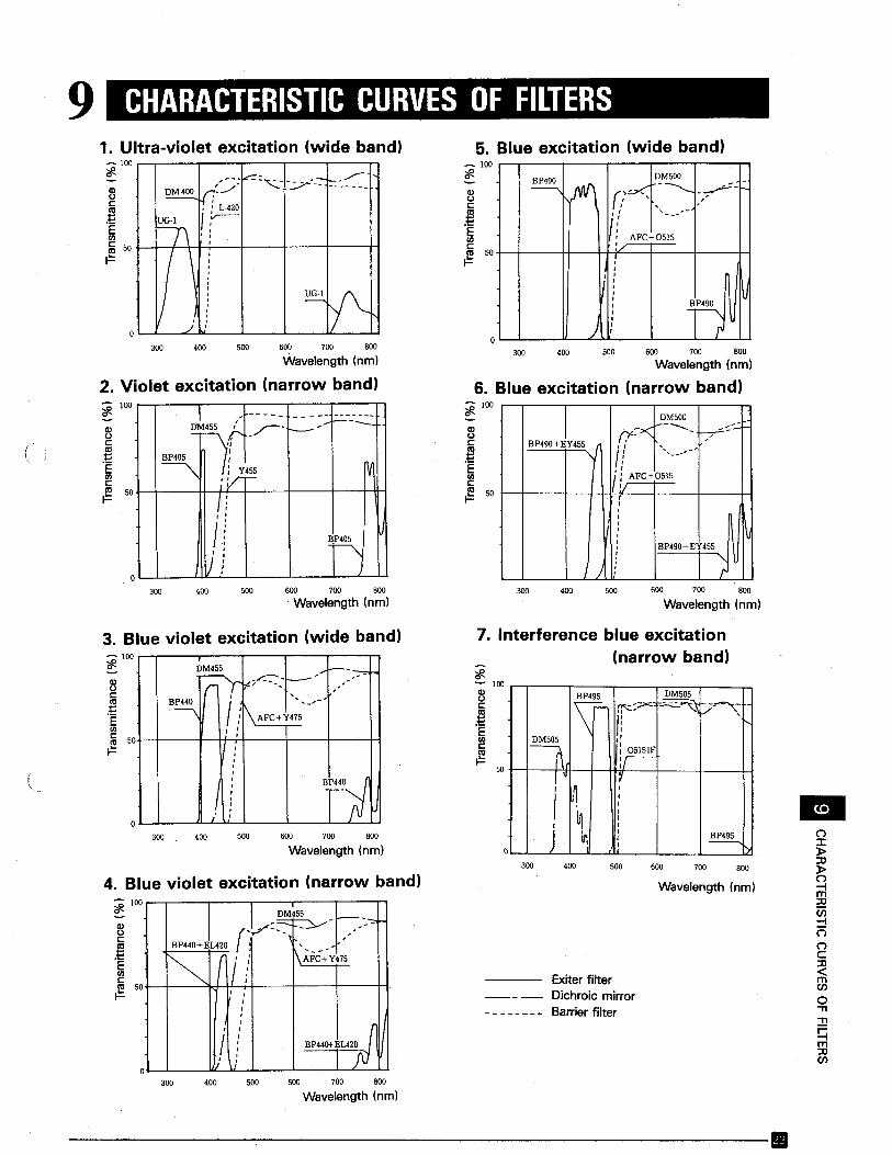
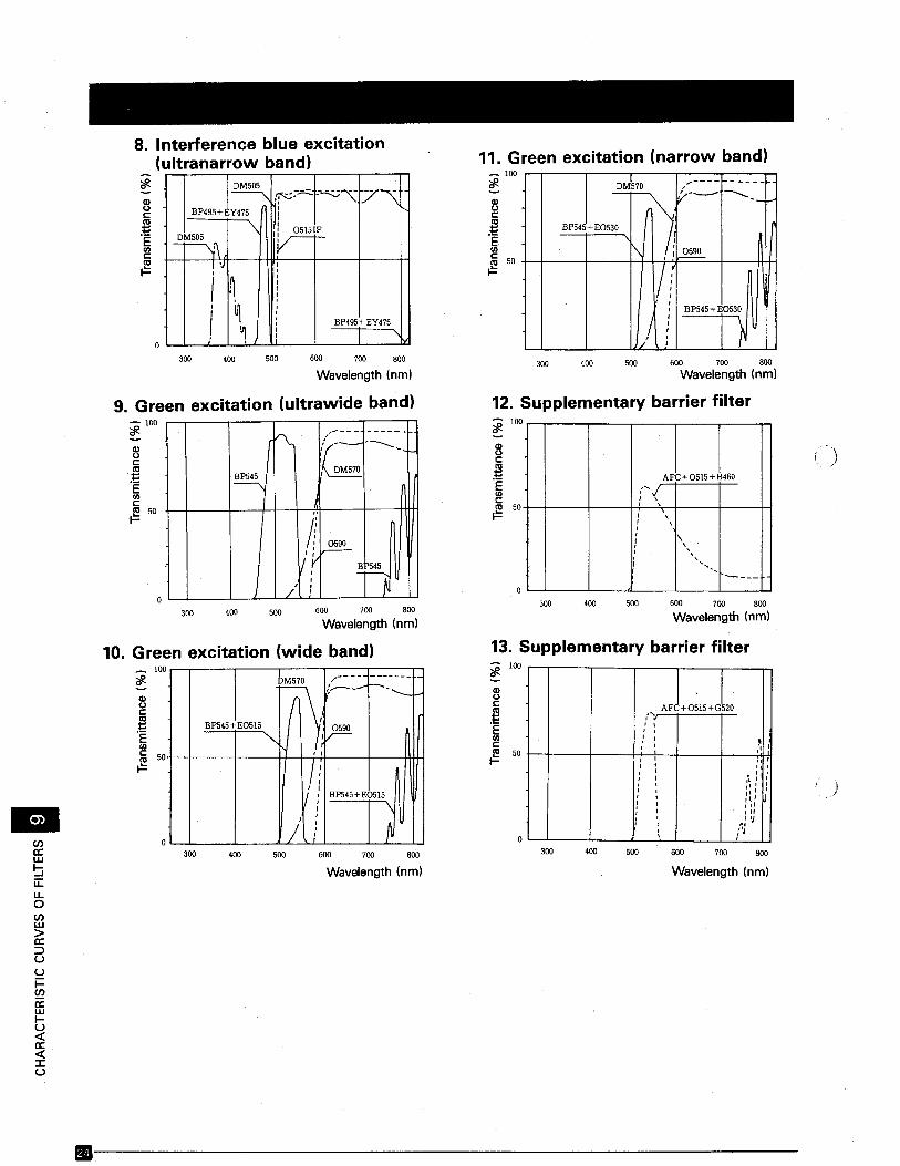
9 CHARACTERISTIC CURVES OF FILTERS
~ ;N\ (?=--<~M~
;,/-
,
if---
AFC+0515:/II
I IIIJ
I~,
~IJI
)I,
5. Blue excitation (wide band)_ 100
'#.
2lc:
.t!EUlc:Cll 50F
2lc:
.t!EUl
16 50 +--+--+-+J-;---+---+------jf---HF
1. Ultra-violet excitation (wide band)- 100 ....-..,-----,,....---.---..,-----,---,-,'#.
I~
Y_M500 __
/';<':><. ...........- -----r:- -:. -f .. ,I! "'---'-'I
I':AFC+05IS
!/
500
I,, :,,
: BP490+EY455
! --...' : r
400300 600 700 800
Wavelength (nm)
6. Blue excitation (narrow band)-100'#.
CDoc:
.t!E~~ 50 1-4--,..-I--l--I-J!l..4---J.-----l---1-J
500400
I ' ----- -----~-----
~M0455.f -~- ---,;- ---~;
"\ ; Y455 M:v-IiIf
I) ;
300
~ 100 r--,-----,,..--...,--.....--;-----,n
CDcc:
.t!EUlc:~ 50+--+---H--H--t---+---1--+-IH
600 700 800
Wavelength (nm)
2. Violet excitation (narrow band)
(
300 400 500 600 700 800
Wavelength (nm)300 400 500 600 700 800
Wavelength (nrn)
4. Blue violet excitation (narrow band)
(""):::c~:rl~
~m:rlen:::!("")
("")C:rl<meno-n:!:!Cjm:rlen
•800700
Wavelength Inrn)
600400 500
Exiter filterDichroic mirrorBarrier filter
300
I~~~;;x::.:
.~[7"'''':~~
/1
I~ :r1 i~
I
~I ,
~1j ~ I ~, I
50
'#.-]00
sc:
.t!EUlcCllF
7. Interference blue excitation(narrow band)
800700
Wavelength (nm)600500400300
J. I _~~_e-:-".~---~ - -:
BP440+EL420 (, ' < ; -,' ,r-. (Ii! I\AFC+Y475
, ,II,I
BP44(}i-EL420 nil. ,
III,,
fJ1/ ,,
D~"";~----,,,---:-.,;,,, ...... -
""" r i:' '
I\AFC+Y4:S'---
I I,,,,., nI,,I,I
":
~ 100
sc:
.t!EUlc:Cll 50F
2lc
.t!EUl
lij soF
3. Blue violet excitation (wide band)~ 100
300 400 Soo 600 700 800
Wavelength (nrn)
--------------------------.
BPS45+ EOS30
)
~c:
.~E<Il
1ij 50 +-+--+---H++-!JF==-1---m~.=
11. Green excitation (narrow band)- 100 ,--,---,,------r---,--,----.----.-.~
~ ~-...=.:::.. """"-V'-:"7"\~i .BP495+ Y475 ,
-,,I
IrlF
-EM505
~'\ ' -~1 I
! °JI ,"
I ~,,II
~1,, ,
I,,
BP495+ EY475,, I,I
8. Interference blue excitation(ultranarrow band)
~
Wavelength (nrn)
600 700 800
Wavelength (nm)500
500
400
400
300
300
AFC+0515+ B460,-,,I, ,I ,, ,,,
\! ,,r
,,I , , ,
----a
600 700 800Wavelength (nrn)
12. Supplementary barrier filter~ 100
sc:
.~E<Ilc:(ll 50.=
13. Supplementary barrier filter
800700600
500
500
400
400
300
300
r'\.,,--- - ------
,' ... -----....,(DM570
l~."
If~
;~ nJ
,,/' .
I
9. Green excitation (ultrawide band)- 100~
~c
.~E<IlC(ll 50.=
600 700 800
Wavelength (nrnl
10. Green excitation (wide band)
ffit:::-:-;1---------
BP545+E0515~<,
, I
/iI : BP54S+ EOS15
, '\
;'I,
~,,
Wavelength (nrn) Wavelength (nm)
. AFLo~15+10,,'"'.t
" I,I ,, ~,I :'
,, ,,'I , ,, . ' ,,
" , ,I " , ,,
" ',
I ", J, ,,',III, , u, -,
I :~I ,
)
800700600500400300
~100
Q)UC(ll
.;E<Ilc(ll 50.=
800700600500400300
~
sc:
.~E<Il
1ij 50
.=
100
ena:w~u:::u..oenw>a:::Juui=ena:wIU«a:«:::cu
-
.-----------------------
10 USE OF IGS CUBE
(
The IGS cube is used to observe immuno-gold stained specimens.
For observation, use the following items:
* IGS cubeBH2-HMIGS
* ObjectivesD Plan Apo 40 X UV (oil)
D Plan Ape l00x UV (oil)D Apo 40 X UV (oil)D Apo l00x UV (oill
Note:Flare maybecomeprominent during observation. To preventthis, close the reflected lightfluorescence illuminator's apertureirisdiaphragm and field iris diaphragm openings as required.
cCIlmo'TI
G)CIl('")Cttlm
OLYMPUSOLYMPUS OPTICAL CO., LTD.
San-Ei Building, 22-2, Nishi Shinjuku 1-chome, Shinjuku-ku, Tokyo, Japan
OLYMPUS OPTICAL CO., (EUROPA) GMBH.Postfach 104908, W:lndenstrasse 14-16,2000 Hamburg 1, \Nest Germany
OLYMPUS CORPORATION4 Nevada Drive, Lake Success, N.Y. 11042-1179,U.S.A.
OLYMPUS OPTICAL CO. (U.K.) LTD.2-8 Honduras Street, London EC1YOTX
The design of the product is under constant review and whilst every effort ismade to keep th is manual up to date, the right is reserved to change specifications and equipment at any time without prior notice.
)