Embed Size (px)
Citation preview

B26PS((((AAAATTTT22226666CCCCSSSSMMMMCCCC))))
GB Operator’s manual 2-27 SE Bruksanvisning 28-54 DK Brugsanvisning 55-79 FI Käyttöohje 80-105 NO Bruksanvisning 106-131 FR Manuel d’utilisation 132-157 NL Gebruiksaanwijzing 158-184 IT Istruzioni per l’uso 185-210 ES Manual de instrucciones 211-236 DE Bedienungsanweisung 235-262 PT Instruções para o uso 263-288HU Használati utasítás 289-314 PL Instrukcja obs∏ugi 315-340 EE Käsitsemisõpetus 341-366 LV Lieto‰anas pamÇc¥ba 367-392
LT Naudojimosi instrukcijos 393-418 SK Návod na obsluhu 419-444 RS Priruãnik 445-470 HR Priruãnik 470-496 SI Navodila za uporabo 497-522 BA Uputstvo o upotrebi 523-548 CZ Návod k pouÏití 549-574 RU �óêîâîäñòâî ïî
ýêñïëóàòàöèè 575-602BG �úêîâîäñòâî çà
åêñïëîàòàöèß 603-629 UA �îñ´áíèê êîðèñòóâà÷à 630-656 GR √‰ËÁ›Â˜ ¯Ú‹Ûˆ˜ 657-683 TR Kullanım kılavuzu 684-709 RO Instrucöiuni de utilizare 711-735

KEY TO SYMBOLS
2 – English
SymbolsWARNING! A brushcutter or trimmer can be dangerous if used incorrectly or carelessly, and can cause serious or fatal injury to the operator or others. It is extremely important that you read and understand the contents of this operator’s manual.
Please read the operator’s manual carefully and make sure you understand the instructions before using the machine.
Always wear:• Wear a protective helmet where there is a
risk of falling objects• Approved hearing protection• Approved eye protection
Max. speed of output shaft, rpm
This product is in accordance with applicable EC directives.
Watch out for thrown objects and ricochets.
The operator of the machine must ensure, while working, that no persons or animals come closer than 15 meters.
Machines fitted with saw blades or grass blades can be thrown violently to the side when the blade comes into contact with a fixed object. This is called blade thrust. The blade is capable of amputating an arm or leg. Always keep people and animals at least 15 meters from the machine.
Arrows which show limits for handle positioning.
Always wear approved protective gloves.
Wear sturdy, non-slip boots.
Make sure your hair does not hang below shoulder level.
Choke: Set the choke control in the choke position.
Set the choke control in the RUN position.
Primer bulb
Refuelling.
Noise emission to the environment according to the European Community’s Directive. The machine’s emission is specified in the Technical data chapter and on the label.
Other symbols/decals on the machine refer to special certification requirements for certain markets.
The engine is switched off by moving the stop switch to the stop position. CAUTION! The stop switch automatically returns to the start position. In order to prevent unintentional starting, the spark plug cap must be removed from the spark plug when assembling, checking and/or performing maintenance.
Always wear approved protective gloves.
Regular cleaning is required.
Visual check.
Approved eye protection must always be used.
10000

CONTENTS
Contents Note the following before starting:Please read the operator's manual carefully.
KEY TO SYMBOLSSymbols ................................................................ 2
CONTENTSContents ............................................................... 3
Note the following before starting: ........................ 3
INTRODUCTIONDear Customer, .................................................... 4
WHAT IS WHAT?What is what on the trimmer and the brushcutter? 5
GENERAL SAFETY PRECAUTIONSImportant .............................................................. 6
Personal protective equipment ............................. 6
Machine′s safety equipment ................................. 7
Cutting equipment ................................................ 9
ASSEMBLYFitting the P-barrier ............................................... 11
Assembling and dismantling the two-piece shaft . 11
Fitting blades and trimmer heads ......................... 12
Fitting the transport guard .................................... 13
Adjusting the harness ........................................... 13
FUEL HANDLINGFuel safety ............................................................ 14
Fuel ...................................................................... 14
Fueling .................................................................. 15
STARTING AND STOPPINGCheck before starting ........................................... 16
Starting and stopping ........................................... 16
WORKING TECHNIQUESGeneral working instructions ................................ 19
MAINTENANCECarburettor ........................................................... 22
Muffler .................................................................. 22
Cooling system ..................................................... 22
Spark plug ............................................................ 23
Two-piece shaft ................................................... 23
Air filter ................................................................. 23
Checking and adjusting of throttle wire ................ 24
Maintenance schedule ......................................... 25
TECHNICAL DATATechnical data ...................................................... 26
EC Declaration of Conformity ............................... 27
!WARNING! Long-term exposure to noise can result in permanent hearing impairment. So always use approved hearing protection.
!WARNING! Under no circumstances may the design of the machine be modified without the permission of the manufacturer. Always use original accessories. Non-authorized modifications and/or accessories can result in serious personal injury or the death of the operator or others.
!WARNING! A brushcutter or trimmer can be dangerous if used incorrectly or carelessly, and can cause serious or fatal injury to the operator or others. It is extremely important that you read and understand the contents of this operator’s manual.
English – 3

INTRODUCTION
Dear Customer,Thank you for choosing a McCulloch product. You are thereby part of a story that started long ago, when the McCulloch Corporation started its manufacturing of engines during World War II. In 1949, when McCulloch introduced its first light one-man chainsaw, woodworking would never be the same again.
The line of innovative chainsaws would continue over the decades, and business was expanded, first by airplane and kart engines in the 1950s, then by mini chainsaws in the 1960s. Later, in the 1970s and 80s, trimmers and blower vacs were added to the range.
Today, as a part of the Husqvarna group, McCulloch continues the tradition of powerful engines, technical innovations, and strong designs that have been our hallmarks for more than half a century. Lowering fuel consumption, emissions and noise levels are of top priority to us, as is improving safety and user-friendliness.
We certainly hope that you will be satisfied with your McCulloch product, as it is designed to be your companion for a long time. By following this operators manual’s advice on usage, service, and maintenance, its lifespan can be extended. If you should need professional help with repair or service, please use the Service Locator at www.mcculloch.com.
McCulloch has a policy of continuous product development and therefore reserves the right to modify the design and appearance of products without prior notice.
This manual can also be downloaded at www.mcculloch.com.
English – 4

English – 5
WHAT IS WHAT?
What is what on the trimmer and the brushcutter?
5
6
14
15
8
7
10
1
18
11
16
12
13
21
4
9
19
1
32
4
4
2022
2324
1717
26
25
27
28
1 Trimmer head
2 Grease filler cap, bevel gear
3 Bevel gear
4 Cutting attachment guard
5 Shaft
6 Shaft coupling
7 Loop handle
8 Throttle trigger
9 Stop switch
10 Throttle lockout
11 Spark plug cap and spark plug
12 Starter handle
13 Fuel tank
14 Air filter cover
15 Primer bulb
16 Choke control
17 Drive disc
18 Operator′s manual
19 Spanner
20 Blade
21 P-barrier
22 Support flange
23 Washer
24 Locking nut
25 Harness
26 Suspension ring
27 Locking pin
28 Transport guard
29 Hedge trimmer attachment (only some models)
GENERAL SAFETY PRECAUTIONS
6 – English
Important
Personal protective equipment
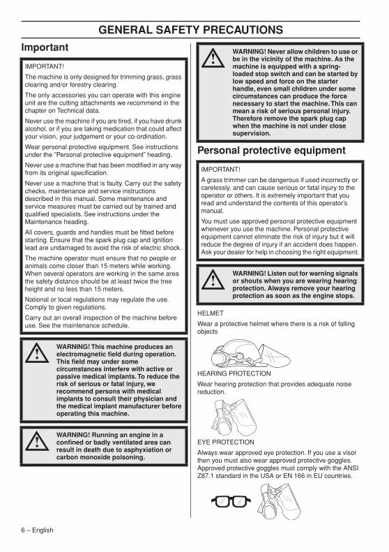
HELMET
Wear a protective helmet where there is a risk of falling objects
HEARING PROTECTION
Wear hearing protection that provides adequate noise reduction.
EYE PROTECTION
Always wear approved eye protection. If you use a visor then you must also wear approved protective goggles. Approved protective goggles must comply with the ANSI Z87.1 standard in the USA or EN 166 in EU countries.
IMPORTANT!
The machine is only designed for trimming grass, grass clearing and/or forestry clearing.
The only accessories you can operate with this engine unit are the cutting attachments we recommend in the chapter on Technical data.
Never use the machine if you are tired, if you have drunk alcohol, or if you are taking medication that could affect your vision, your judgement or your co-ordination.
Wear personal protective equipment. See instructions under the ”Personal protective equipment” heading.
Never use a machine that has been modified in any way from its original specification.
Never use a machine that is faulty. Carry out the safety checks, maintenance and service instructions described in this manual. Some maintenance and service measures must be carried out by trained and qualified specialists. See instructions under the Maintenance heading.
All covers, guards and handles must be fitted before starting. Ensure that the spark plug cap and ignition lead are undamaged to avoid the risk of electric shock.
The machine operator must ensure that no people or animals come closer than 15 meters while working. When several operators are working in the same area the safety distance should be at least twice the tree height and no less than 15 meters.
National or local regulations may regulate the use. Comply to given regulations.
Carry out an overall inspection of the machine before use. See the maintenance schedule.
!WARNING! This machine produces an electromagnetic field during operation. This field may under some circumstances interfere with active or passive medical implants. To reduce the risk of serious or fatal injury, we recommend persons with medical implants to consult their physician and the medical implant manufacturer before operating this machine.
!WARNING! Running an engine in a confined or badly ventilated area can result in death due to asphyxiation or carbon monoxide poisoning.
!WARNING! Never allow children to use or be in the vicinity of the machine. As the machine is equipped with a spring-loaded stop switch and can be started by low speed and force on the starter handle, even small children under some circumstances can produce the force necessary to start the machine. This can mean a risk of serious personal injury. Therefore remove the spark plug cap when the machine is not under close supervision.
IMPORTANT!
A grass trimmer can be dangerous if used incorrectly or carelessly, and can cause serious or fatal injury to the operator or others. It is extremely important that you read and understand the contents of this operator’s manual.
You must use approved personal protective equipment whenever you use the machine. Personal protective equipment cannot eliminate the risk of injury but it will reduce the degree of injury if an accident does happen. Ask your dealer for help in choosing the right equipment.
!WARNING! Listen out for warning signals or shouts when you are wearing hearing protection. Always remove your hearing protection as soon as the engine stops.
GENERAL SAFETY PRECAUTIONS
English – 7
GLOVES
Gloves should be worn when necessary, e.g. when fitting cutting attachments.
BOOTS
Wear boots with steel toe-caps and non-slip sole.
CLOTHING
Wear clothes made of a strong fabric and avoid loose clothing that can catch on twigs and branches. Always wear heavy, long pants. Do not wear jewellery, shorts sandals or go barefoot. Secure hair so it is above shoulder level.
FIRST AID KIT
Always have a first aid kit nearby.
Machine′s safety equipmentThis section describes the machine′s safety equipment, its purpose, and how checks and maintenance should be carried out to ensure that it operates correctly. See the ”What is what?” section to locate where this equipment is positioned on your machine.
The life span of the machine can be reduced and the risk of accidents can increase if machine maintenance is not carried out correctly and if service and/or repairs are not carried out professionally. If you need further information please contact your nearest service workshop.
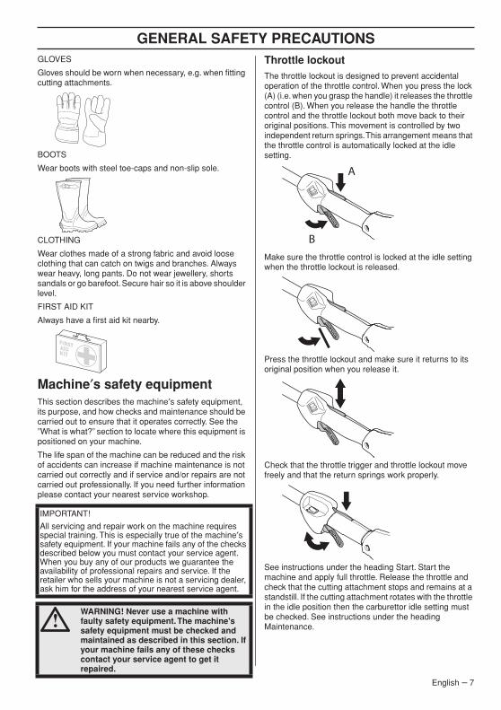
Throttle lockoutThe throttle lockout is designed to prevent accidental operation of the throttle control. When you press the lock (A) (i.e. when you grasp the handle) it releases the throttle control (B). When you release the handle the throttle control and the throttle lockout both move back to their original positions. This movement is controlled by two independent return springs. This arrangement means that the throttle control is automatically locked at the idle setting.
Make sure the throttle control is locked at the idle setting when the throttle lockout is released.
Press the throttle lockout and make sure it returns to its original position when you release it.
Check that the throttle trigger and throttle lockout move freely and that the return springs work properly.
See instructions under the heading Start. Start the machine and apply full throttle. Release the throttle and check that the cutting attachment stops and remains at a standstill. If the cutting attachment rotates with the throttle in the idle position then the carburettor idle setting must be checked. See instructions under the heading Maintenance.
IMPORTANT!
All servicing and repair work on the machine requires special training. This is especially true of the machine′s safety equipment. If your machine fails any of the checks described below you must contact your service agent. When you buy any of our products we guarantee the availability of professional repairs and service. If the retailer who sells your machine is not a servicing dealer, ask him for the address of your nearest service agent.
!WARNING! Never use a machine with faulty safety equipment. The machine's safety equipment must be checked and maintained as described in this section. If your machine fails any of these checks contact your service agent to get it repaired.
A
B
GENERAL SAFETY PRECAUTIONS
8 – English
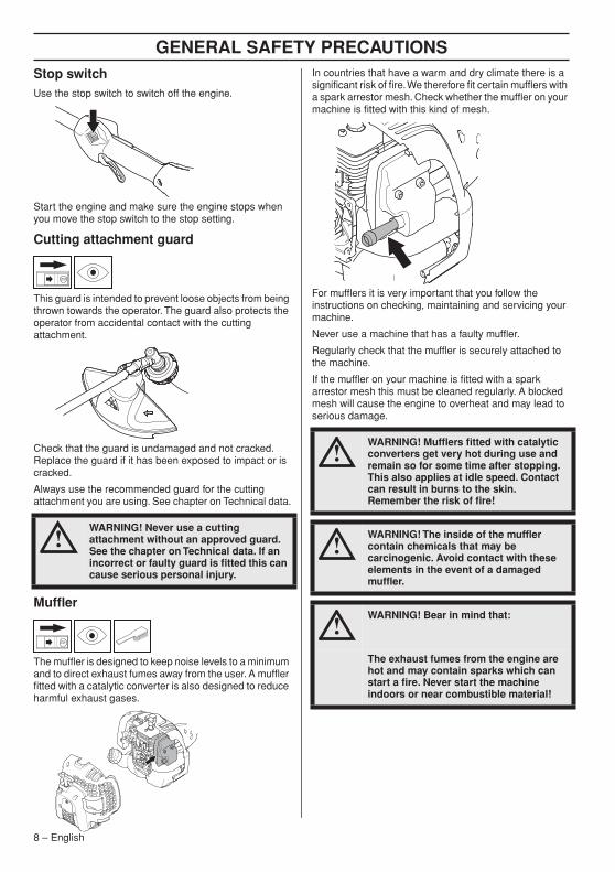
Stop switchUse the stop switch to switch off the engine.
Start the engine and make sure the engine stops when you move the stop switch to the stop setting.
Cutting attachment guard
This guard is intended to prevent loose objects from being thrown towards the operator. The guard also protects the operator from accidental contact with the cutting attachment.
Check that the guard is undamaged and not cracked. Replace the guard if it has been exposed to impact or is cracked.
Always use the recommended guard for the cutting attachment you are using. See chapter on Technical data.
Muffler
The muffler is designed to keep noise levels to a minimum and to direct exhaust fumes away from the user. A muffler fitted with a catalytic converter is also designed to reduce harmful exhaust gases.
In countries that have a warm and dry climate there is a significant risk of fire. We therefore fit certain mufflers with a spark arrestor mesh. Check whether the muffler on your machine is fitted with this kind of mesh.
For mufflers it is very important that you follow the instructions on checking, maintaining and servicing your machine.
Never use a machine that has a faulty muffler.
Regularly check that the muffler is securely attached to the machine.
If the muffler on your machine is fitted with a spark arrestor mesh this must be cleaned regularly. A blocked mesh will cause the engine to overheat and may lead to serious damage.
!WARNING! Never use a cutting attachment without an approved guard. See the chapter on Technical data. If an incorrect or faulty guard is fitted this can cause serious personal injury.
!WARNING! Mufflers fitted with catalytic converters get very hot during use and remain so for some time after stopping. This also applies at idle speed. Contact can result in burns to the skin. Remember the risk of fire!
!WARNING! The inside of the muffler contain chemicals that may be carcinogenic. Avoid contact with these elements in the event of a damaged muffler.
!WARNING! Bear in mind that:
The exhaust fumes from the engine are hot and may contain sparks which can start a fire. Never start the machine indoors or near combustible material!
GENERAL SAFETY PRECAUTIONS
English – 9
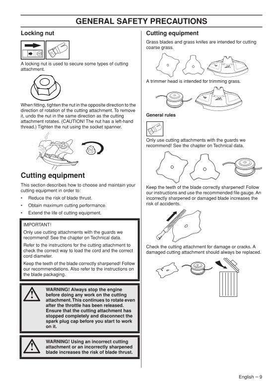
Locking nut
A locking nut is used to secure some types of cutting attachment.
When fitting, tighten the nut in the opposite direction to the direction of rotation of the cutting attachment. To remove it, undo the nut in the same direction as the cutting attachment rotates. (CAUTION! The nut has a left-hand thread.) Tighten the nut using the socket spanner.
Cutting equipmentThis section describes how to choose and maintain your cutting equipment in order to:
• Reduce the risk of blade thrust.
• Obtain maximum cutting performance.
• Extend the life of cutting equipment.
Cutting equipmentGrass blades and grass knifes are intended for cutting coarse grass.
A trimmer head is intended for trimming grass.
General rules
Only use cutting attachments with the guards we recommend! See the chapter on Technical data.
Keep the teeth of the blade correctly sharpened! Follow our instructions and use the recommended file gauge. An incorrectly sharpened or damaged blade increases the risk of accidents.
Check the cutting attachment for damage or cracks. A damaged cutting attachment should always be replaced.
IMPORTANT!
Only use cutting attachments with the guards we recommend! See the chapter on Technical data.
Refer to the instructions for the cutting attachment to check the correct way to load the cord and the correct cord diameter.
Keep the teeth of the blade correctly sharpened! Follow our recommendations. Also refer to the instructions on the blade packaging.
!WARNING! Always stop the engine before doing any work on the cutting attachment. This continues to rotate even after the throttle has been released. Ensure that the cutting attachment has stopped completely and disconnect the spark plug cap before you start to work on it.
!WARNING! Using an incorrect cutting attachment or an incorrectly sharpened blade increases the risk of blade thrust.
GENERAL SAFETY PRECAUTIONS
10 – English
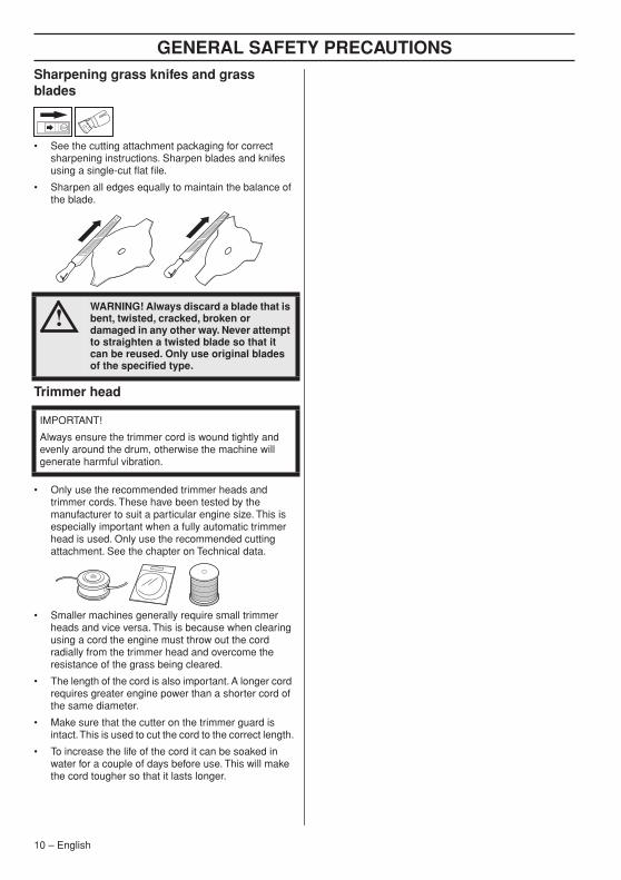
Sharpening grass knifes and grass blades
• See the cutting attachment packaging for correct sharpening instructions. Sharpen blades and knifes using a single-cut flat file.
• Sharpen all edges equally to maintain the balance of the blade.
Trimmer head
• Only use the recommended trimmer heads and trimmer cords. These have been tested by the manufacturer to suit a particular engine size. This is especially important when a fully automatic trimmer head is used. Only use the recommended cutting attachment. See the chapter on Technical data.
• Smaller machines generally require small trimmer heads and vice versa. This is because when clearing using a cord the engine must throw out the cord radially from the trimmer head and overcome the resistance of the grass being cleared.
• The length of the cord is also important. A longer cord requires greater engine power than a shorter cord of the same diameter.
• Make sure that the cutter on the trimmer guard is intact. This is used to cut the cord to the correct length.
• To increase the life of the cord it can be soaked in water for a couple of days before use. This will make the cord tougher so that it lasts longer.
!WARNING! Always discard a blade that is bent, twisted, cracked, broken or damaged in any other way. Never attempt to straighten a twisted blade so that it can be reused. Only use original blades of the specified type.
IMPORTANT!
Always ensure the trimmer cord is wound tightly and evenly around the drum, otherwise the machine will generate harmful vibration.
ASSEMBLY
English – 11
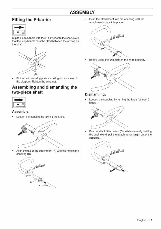
Fitting the P-barrier
Clip the loop handle with the P-barrier onto the shaft. Note that the loop handle must be fitted between the arrows on the shaft.
• Fit the bolt, securing plate and wing nut as shown in the diagram. Tighten the wing nut.
Assembling and dismantling the two-piece shaft
Assembly:• Loosen the coupling by turning the knob.
• Align the tab of the attachment (A) with the hole in the coupling (B).
• Push the attachment into the coupling until the attachment snaps into place.
• Before using the unit, tighten the knob securely.
Dismantling:• Loosen the coupling by turning the knob (at least 3
times).
• Push and hold the button (C). While securely holding the engine end, pull the attachment straight out of the coupling.
BA
C

ASSEMBLY
12 – English
Fitting blades and trimmer heads
Fitting a blade guard, grass blade and grass cutter
• Hook the blade guard/combination guard (A) onto the fitting on the shaft and secure with the bolt (L). Use the recommended blade guard. See the Technical data section. CAUTION! Ensure that the guard extension is removed.
• Fit the drive disc (B) on the output shaft.
• Turn the output shaft until one of the holes in the drive disc aligns with the corresponding hole in the gear housing.
• Insert the locking pin (C) in the hole to lock the shaft.
• Place the blade (D), support flange (E) and support cup (F) on the output shaft.
• Fit the nut (G). The nut must be tightened to a torque of 35-50 Nm (3.5-5 kpm). Use the socket spanner in the tool kit. Hold the shaft of the spanner as close to the blade guard as possible. To tighten the nut, turn the spanner in the opposite direction to the direction of rotation (Caution! left-hand thread).
Fitting the trimmer guard and trimmer head
• Fit the correct trimmer guard (A) for use with the trimmer head.
• Hook the trimmer guard/combination guard onto the fitting on the shaft and secure with the bolt (L).
• Fit the drive disc (B) on the output shaft.
• Turn the output shaft until one of the holes in the drive disc aligns with the corresponding hole in the gear housing.
• Insert the locking pin (C) in the hole to lock the shaft.
!WARNING!
When fitting the cutting attachment it is extremely important that the raised section on the drive disc/support flange engages correctly in the centre hole of the cutting attachment. If the cutting attachment is fitted incorrectly it can result in serious and/or fatal personal injury.
!WARNING! Never use a cutting attachment without an approved guard. See the chapter on Technical data. If an incorrect or faulty guard is fitted this can cause serious personal injury.
IMPORTANT! If a saw blade or grass blade are to be used the machine must be equipped with the correct handlebar, blade guard and harness.
L
A
GF
B
A
E
D
C
L
A
B
H
A
C

ASSEMBLY
English – 13
• Screw on the trimmer head/plastic blades (H) anticlockwise.
• To dismantle, follow the instructions in the reverse order.
Fitting the transport guard
Attach the transport cover on the blade as shown.
Adjusting the harnessA correctly adjusted harness and machine significantly facilitates the work. Adjust the harness to give the best working position.

FUEL HANDLING
14 – English
Fuel safetyNever start the machine:
1 If you have spilled fuel on it. Wipe off the spillage and allow remaining fuel to evaporate.
2 If you have spilled fuel on yourself or your clothes, change your clothes. Wash any part of your body that has come in contact with fuel. Use soap and water.
3 If the machine is leaking fuel. Check regularly for leaks from the fuel cap and fuel lines.
Transport and storage• Store and transport the machine and fuel so that there
is no risk of any leakage or fumes coming into contact with sparks or open flames, for example, from electrical machinery, electric motors, electrical relays/switches or boilers.
• When storing and transporting fuel always use approved containers intended for this purpose.
• When storing the machine for long periods the fuel tank must be emptied. Contact your local petrol station to find out where to dispose of excess fuel.
• Ensure the machine is cleaned and that a complete service is carried out before long-term storage.
• The transport guard must always be fitted to the cutting attachment when the machine is being transported or in storage.
• Secure the machine during transport to prevent loss of fuel, damage or injury.
• In order to prevent unintentional starting of the engine, the spark plug cap must always be removed during long-term storage, if the machine is not under close supervision and when performing all service measures.
FuelCAUTION! The machine is equipped with a two-stroke engine and must always be run using a mixture of petrol and two-stroke oil. It is important to accurately measure the amount of oil to be mixed to ensure that the correct mixture is obtained. When mixing small amounts of fuel, even small inaccuracies can drastically affect the ratio of the mixture.
Petrol
CAUTION! Always use a quality petrol/oil mixture at least 90 octane (RON). If your machine is equipped with a catalytic converter (see chapter on Technical data) always use a good quality unleaded petrol/oil mixture. Leaded petrol will destroy the catalytic converter.
Use low-emission petrol, also known as alkylate petrol, if it is available.
Ethanol blended fuel, E10 may be used (max 10% ethanol blend). Using ethanol blends higher than E10 will create lean running condition which can cause engine damage.
• The lowest octane recommended is 90 (RON). If you run the engine on a lower octane grade than 90 so-called knocking can occur. This gives rise to a high engine temperature, which can result in serious engine damage.
• When working at continuous high revs a higher octane rating is recommended.
Two-stroke oil• For best results and performance use Universal,
Universal powered by McCULLOCH two-stroke engine oil, which is specially formulated for our air-cooled two-stroke engines.
• Never use two-stroke oil intended for water-cooled engines, sometimes referred to as outboard oil (rated TCW).
• Never use oil intended for four-stroke engines.
• A poor oil quality and/or too high oil/fuel ratio may jeopardise function and decrease the life time of catalytic converters.
• Mixing ratio
!WARNING! Take care when handling fuel. Bear in mind the risk of fire, explosion and inhaling fumes.
!WARNING! Fuel and fuel fumes are highly inflammable and can cause serious injury when inhaled or allowed to come in contact with the skin. For this reason observe caution when handling fuel and make sure there is adequate ventilation.
Petrol Two-stroke oil, litre 40:1
1 U.S. Gal. 3.2 oz. 95 ml (cc)
5 liters 4.3 oz. 125 ml (cc)
1 lmp. Gal. 4.3 oz. 125 ml (cc)
mixing procedure
40 parts gasoline and 1 part two stroke oil.
1 ml = 1 cc
FUEL HANDLING
English – 15
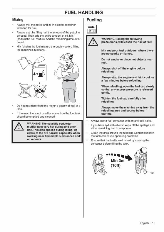
Mixing• Always mix the petrol and oil in a clean container
intended for fuel.
• Always start by filling half the amount of the petrol to be used. Then add the entire amount of oil. Mix (shake) the fuel mixture. Add the remaining amount of petrol.
• Mix (shake) the fuel mixture thoroughly before filling the machine’s fuel tank.
• Do not mix more than one month’s supply of fuel at a time.
• If the machine is not used for some time the fuel tank should be emptied and cleaned.
Fueling
• Always use a fuel container with an anti-spill valve.
• If you have spilled fuel on it. Wipe off the spillage and allow remaining fuel to evaporate.
• Clean the area around the fuel cap. Contamination in the tank can cause operating problems.
• Ensure that the fuel is well mixed by shaking the container before filling the tank.
!WARNING! The catalytic converter muffler gets very hot during and after use. This also applies during idling. Be aware of the fire hazard, especially when working near flammable substances and/or vapours.
!WARNING! Taking the following precautions, will lessen the risk of fire:
Mix and pour fuel outdoors, where there are no sparks or flames.
Do not smoke or place hot objects near fuel.
Always shut off the engine before refuelling.
Always stop the engine and let it cool for a few minutes before refuelling.
When refuelling, open the fuel cap slowly so that any excess pressure is released gently.
Tighten the fuel cap carefully after refuelling.
Always move the machine away from the refuelling area and source before starting.
STARTING AND STOPPING
16 – English
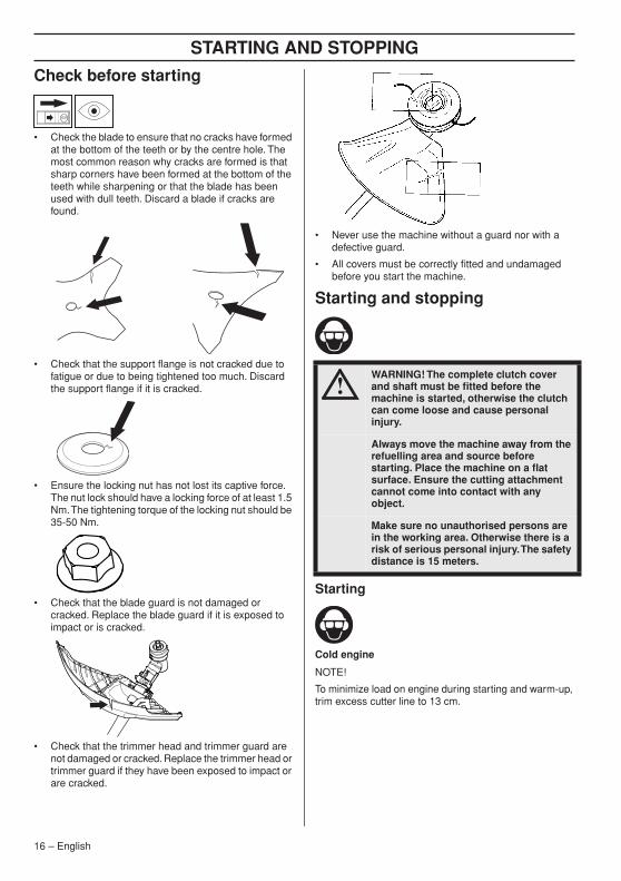
Check before starting
• Check the blade to ensure that no cracks have formed at the bottom of the teeth or by the centre hole. The most common reason why cracks are formed is that sharp corners have been formed at the bottom of the teeth while sharpening or that the blade has been used with dull teeth. Discard a blade if cracks are found.
• Check that the support flange is not cracked due to fatigue or due to being tightened too much. Discard the support flange if it is cracked.
• Ensure the locking nut has not lost its captive force. The nut lock should have a locking force of at least 1.5 Nm. The tightening torque of the locking nut should be 35-50 Nm.
• Check that the blade guard is not damaged or cracked. Replace the blade guard if it is exposed to impact or is cracked.
• Check that the trimmer head and trimmer guard are not damaged or cracked. Replace the trimmer head or trimmer guard if they have been exposed to impact or are cracked.
• Never use the machine without a guard nor with a defective guard.
• All covers must be correctly fitted and undamaged before you start the machine.
Starting and stopping
Starting
Cold engine
NOTE!
To minimize load on engine during starting and warm-up, trim excess cutter line to 13 cm.
!WARNING! The complete clutch cover and shaft must be fitted before the machine is started, otherwise the clutch can come loose and cause personal injury.
Always move the machine away from the refuelling area and source before starting. Place the machine on a flat surface. Ensure the cutting attachment cannot come into contact with any object.
Make sure no unauthorised persons are in the working area. Otherwise there is a risk of serious personal injury. The safety distance is 15 meters.
STARTING AND STOPPING
English – 17
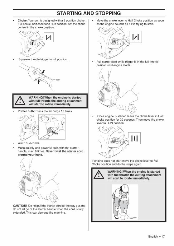
• Choke: Your unit is designed with a 3 position choke: Full choke, half chokeand Run position. Set the choke control in the choke position.
• Squeeze throttle trigger in full position.
• Primer bulb: Press the air purge 10 times.
• Wait 10 seconds.
• Make quickly and powerful pulls with the starter handle, max. 6 times. Never twist the starter cord around your hand.
CAUTION! Do not pull the starter cord all the way out and do not let go of the starter handle when the cord is fully extended. This can damage the machine.
• Move the choke lever to Half Choke position as soon as the engine sounds as if it is trying to start.
• Pull starter cord while trigger is in the full throttle position until engine starts.
• Once engine is started leave the choke lever in Half choke position for 20 seconds. Then move the choke lever to RUN position.
If engine does not start move the choke lever to Full Choke position and do the steps again.
!WARNING! When the engine is started with full throttle the cutting attachment will start to rotate immediately.
x10
!WARNING! When the engine is started with full throttle the cutting attachment will start to rotate immediately.

STARTING AND STOPPING
18 – English
Always pull starter cord straight out. Pulling the starter at an angle will cause cord to rub against the eyelet. This friction will cause the cord to fray and wear more quickly. Always hold the starter handle when cord retracts. Never allow cord to snap back from extended position. This could cause cord to snag or fray and also damage the starter assembly.
Warm engine
• Set the choke control in the RUN position.
• Then grasp the starter handle with your right hand and pull the starter cord.
Stopping
Stop the engine by switching off the ignition.
CAUTION! The stop switch automatically returns to the start position. In order to prevent unintentional starting, the spark plug cap must be removed from the spark plug when assembling, checking and/or performing maintenance.
WORKING TECHNIQUES
English – 19
General working instructions
Basic safety rules
1 Look around you:
• To ensure that people, animals or other things cannot affect your control of the machine.
• To ensure that people, animals, etc., do not come into contact with the cutting attachment or loose objects that are thrown out by the cutting attachment.
• CAUTION! Do not use the machine unless you are able to call for help in the event of an accident.
2 Inspect the working area. Remove all loose objects, such as stones, broken glass, nails, steel wire, string, etc. that could be thrown out or become wrapped around the cutting attachment.
3 Do not use the machine in bad weather, such as dense fog, heavy rain, strong wind, intense cold, etc. Working in bad weather is tiring and often brings added risks, such as icy ground, unpredictable felling direction, etc.
4 Wear harness before operation.
5 Make sure you can move and stand safely. Check the area around you for possible obstacles (roots, rocks, branches, ditches, etc.) in case you have to move suddenly. Take great care when working on sloping ground.
6 Keep a good balance and a firm foothold. Do not overreach. Keep proper footing and balance at all times.
7 Always hold the machine with both hands. Hold the machine on the right side of your body.
8 Keep all parts of your body away from the rotating cutting attachment.
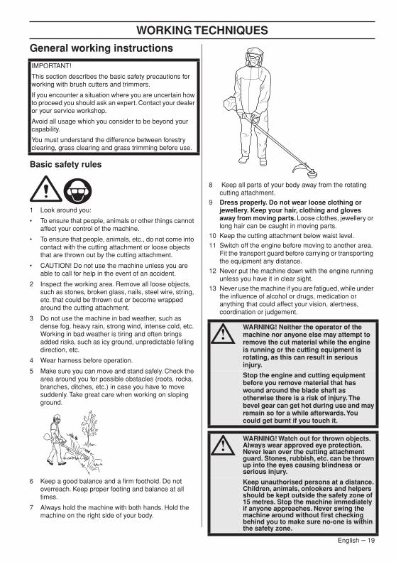
9 Dress properly. Do not wear loose clothing or jewellery. Keep your hair, clothing and gloves away from moving parts. Loose clothes, jewellery or long hair can be caught in moving parts.
10 Keep the cutting attachment below waist level.
11 Switch off the engine before moving to another area. Fit the transport guard before carrying or transporting the equipment any distance.
12 Never put the machine down with the engine running unless you have it in clear sight.
13 Never use the machine if you are fatigued, while under the influence of alcohol or drugs, medication or anything that could affect your vision, alertness, coordination or judgement.
IMPORTANT!
This section describes the basic safety precautions for working with brush cutters and trimmers.
If you encounter a situation where you are uncertain how to proceed you should ask an expert. Contact your dealer or your service workshop.
Avoid all usage which you consider to be beyond your capability.
You must understand the difference between forestry clearing, grass clearing and grass trimming before use.
!WARNING! Neither the operator of the machine nor anyone else may attempt to remove the cut material while the engine is running or the cutting equipment is rotating, as this can result in serious injury.
Stop the engine and cutting equipment before you remove material that has wound around the blade shaft as otherwise there is a risk of injury. The bevel gear can get hot during use and may remain so for a while afterwards. You could get burnt if you touch it.
!WARNING! Watch out for thrown objects. Always wear approved eye protection. Never lean over the cutting attachment guard. Stones, rubbish, etc. can be thrown up into the eyes causing blindness or serious injury.
Keep unauthorised persons at a distance. Children, animals, onlookers and helpers should be kept outside the safety zone of 15 metres. Stop the machine immediately if anyone approaches. Never swing the machine around without first checking behind you to make sure no-one is within the safety zone.
WORKING TECHNIQUES
20 – English
Basic working techniquesAlways slow the engine to idle speed after each working operation. Long periods at full throttle without any load on the engine can lead to serious engine damage.
Grass clearing using a grass blade
• Grass blades and grass knifes must not be used on woody stems.
• Grass blade is used for all kinds of high or thick grass. The more teeth the blade got the better will the cutting result be.
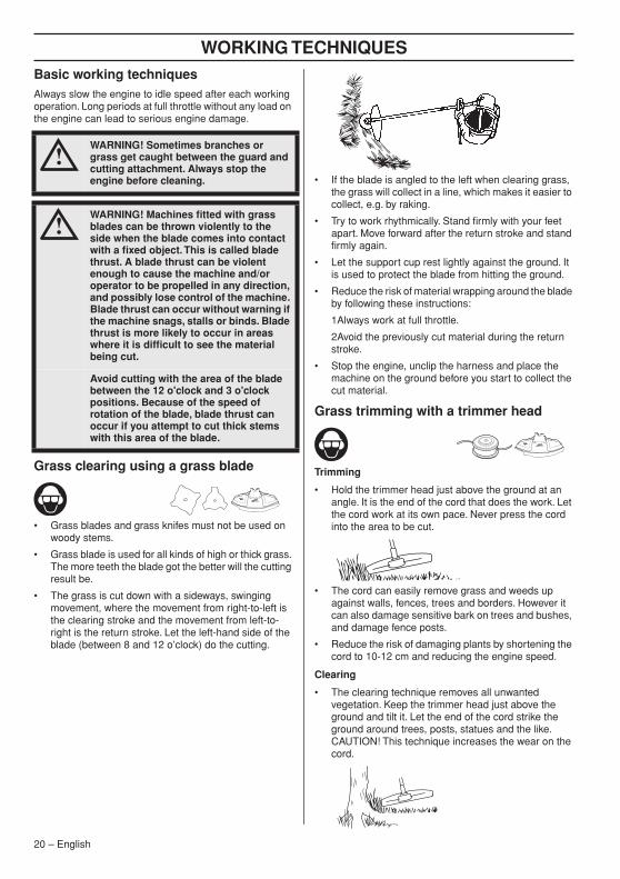
• The grass is cut down with a sideways, swinging movement, where the movement from right-to-left is the clearing stroke and the movement from left-to-right is the return stroke. Let the left-hand side of the blade (between 8 and 12 o’clock) do the cutting.
• If the blade is angled to the left when clearing grass, the grass will collect in a line, which makes it easier to collect, e.g. by raking.
• Try to work rhythmically. Stand firmly with your feet apart. Move forward after the return stroke and stand firmly again.
• Let the support cup rest lightly against the ground. It is used to protect the blade from hitting the ground.
• Reduce the risk of material wrapping around the blade by following these instructions:
1Always work at full throttle.
2Avoid the previously cut material during the return stroke.
• Stop the engine, unclip the harness and place the machine on the ground before you start to collect the cut material.
Grass trimming with a trimmer head
Trimming
• Hold the trimmer head just above the ground at an angle. It is the end of the cord that does the work. Let the cord work at its own pace. Never press the cord into the area to be cut.
• The cord can easily remove grass and weeds up against walls, fences, trees and borders. However it can also damage sensitive bark on trees and bushes, and damage fence posts.
• Reduce the risk of damaging plants by shortening the cord to 10-12 cm and reducing the engine speed.
Clearing
• The clearing technique removes all unwanted vegetation. Keep the trimmer head just above the ground and tilt it. Let the end of the cord strike the ground around trees, posts, statues and the like. CAUTION! This technique increases the wear on the cord.
!WARNING! Sometimes branches or grass get caught between the guard and cutting attachment. Always stop the engine before cleaning.
!WARNING! Machines fitted with grass blades can be thrown violently to the side when the blade comes into contact with a fixed object. This is called blade thrust. A blade thrust can be violent enough to cause the machine and/or operator to be propelled in any direction, and possibly lose control of the machine. Blade thrust can occur without warning if the machine snags, stalls or binds. Blade thrust is more likely to occur in areas where it is difficult to see the material being cut.
Avoid cutting with the area of the blade between the 12 o'clock and 3 o'clock positions. Because of the speed of rotation of the blade, blade thrust can occur if you attempt to cut thick stems with this area of the blade.
WORKING TECHNIQUES
English – 21
• The cord wears quicker and must be fed forward more often when working against stones, brick, concrete, metal fences, etc., than when coming into contact with trees and wooden fences.
• When trimming and clearing, you should use less than full throttle (80%) so that the cord lasts longer and to reduce the wear on the trimmer head.
Cutting
• The trimmer is ideal for cutting grass that is difficult to reach using a normal lawn mower. Keep the cord parallel to the ground when cutting. Avoid pressing the trimmer head against the ground as this can ruin the lawn and damage the tool.
• Do not allow the trimmer head to constantly come into contact with the ground during normal cutting. Constant contact of this type can cause damage and wear to the trimmer head.
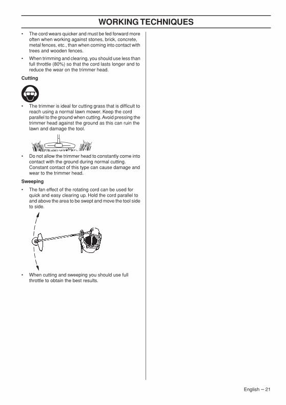
Sweeping
• The fan effect of the rotating cord can be used for quick and easy clearing up. Hold the cord parallel to and above the area to be swept and move the tool side to side.
• When cutting and sweeping you should use full throttle to obtain the best results.

MAINTENANCE
22 – English
Carburettor
Adjustment of the idle speedBefore any adjustments are made, make sure that the air filter is clean and the air filter cover is fitted.
Adjust the idle speed using the idle adjustment screw T, if it is necessary to readjust. First turn the idle adjustment screw T clockwise until the cutting attachment starts to rotate. Then turn the screw anticlockwise until the cutting attachment stops. The idle speed is correctly adjusted when the engine will run smoothly in every position. The idle speed should also be well below the speed at which the cutting attachment starts to rotate.
Recommended idle speed: See the Technical data section.
Muffler
CAUTION! Some mufflers are fitted with a catalytic converter. See chapter on Technical data to see whether your machine is fitted with a catalytic converter.
The muffler is designed to reduce the noise level and to direct the exhaust gases away from the operator. The exhaust gases are hot and can contain sparks, which may cause fire if directed against dry and combustible material.
Some mufflers are equipped with a special spark arrestor mesh. If your machine has this type of muffler, you should clean the mesh at least once a month. This is best done with a wire brush. On mufflers without a catalytic converter the mesh should be cleaned weekly, or replaced if necessary. On mufflers fitted with a catalytic converter the mesh should be checked, and if necessary cleaned, monthly. If the mesh is damaged it should be replaced. If the mesh is frequently blocked, this can be a sign that the performance of the catalytic converter is impaired. Contact your dealer to inspect the muffler. A blocked mesh will cause the machine to overheat and result in damage to the cylinder and piston.
NOTE!
Rear housing shown removed for clarity only. It is not recommended to remove cover for maintenance of screen.
CAUTION! Never use a machine with a defective muffler.
Cooling system
To keep the working temperature as low as possible the machine is equipped with a cooling system.
The cooling system consists of:
1 Air intake on the starter.
2 Cooling fins on the cylinder.
!WARNING! If the idle speed cannot be adjusted so that the cutting attachment stops, contact your dealer/service workshop. Do not use the machine until it has been correctly adjusted or repaired. !
WARNING! Mufflers fitted with catalytic converters get very hot during use and remain so for some time after stopping. This also applies at idle speed. Contact can result in burns to the skin. Remember the risk of fire!
1
2
MAINTENANCE
English – 23
Clean the cooling system with a brush annually or more often in demanding conditions. A dirty or blocked cooling system results in the machine overheating which causes damage to the piston and cylinder.
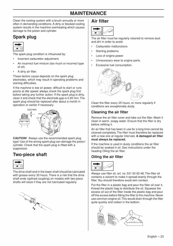
Spark plug
The spark plug condition is influenced by:
• Incorrect carburettor adjustment.
• An incorrect fuel mixture (too much or incorrect type of oil).
• A dirty air filter.
These factors cause deposits on the spark plug electrodes, which may result in operating problems and starting difficulties.
If the machine is low on power, difficult to start or runs poorly at idle speed: always check the spark plug first before taking any further action. If the spark plug is dirty, clean it and check that the electrode gap is 0.65 mm. The spark plug should be replaced after about a month in operation or earlier if necessary.
CAUTION! Always use the recommended spark plug type! Use of the wrong spark plug can damage the piston/cylinder. Check that the spark plug is fitted with a suppressor.
Two-piece shaft
The drive shaft end in the lower shaft should be lubricated with grease every 30 hours. There is a risk that the drive shaft ends (splined coupling) on models with two-piece shafts will seize if they are not lubricated regularly.
Air filter
The air filter must be regularly cleaned to remove dust and dirt in order to avoid:
• Carburettor malfunctions
• Starting problems
• Loss of engine power
• Unnecessary wear to engine parts.
• Excessive fuel consumption.
Clean the filter every 25 hours, or more regularly if conditions are exceptionally dusty.
Cleaning the air filterRemove the air filter cover and take out the filter. Wash it clean in warm, soapy water. Ensure that the filter is dry before refitting it.
An air filter that has been in use for a long time cannot be cleaned completely. The filter must therefore be replaced with a new one at regular intervals. A damaged air filter must always be replaced.
If the machine is used in dusty conditions the air filter should be soaked in oil. See instructions under the heading Oiling the air filter.
Oiling the air filter
Always use filter oil, art. no. 531 00 92-48. The filter oil contains a solvent to make it spread evenly through the filter. You should therefore avoid skin contact.
Put the filter in a plastic bag and pour the filter oil over it. Knead the plastic bag to distribute the oil. Squeeze the excess oil out of the filter inside the plastic bag and pour off the excess before fitting the filter to the machine. Never use common engine oil. This would drain through the filter quite quickly and collect in the bottom.
0,65
MAINTENANCE
24 – English
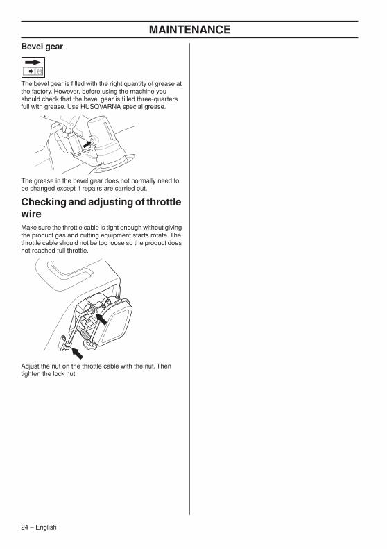
Bevel gear
The bevel gear is filled with the right quantity of grease at the factory. However, before using the machine you should check that the bevel gear is filled three-quarters full with grease. Use HUSQVARNA special grease.
The grease in the bevel gear does not normally need to be changed except if repairs are carried out.
Checking and adjusting of throttle wireMake sure the throttle cable is tight enough without giving the product gas and cutting equipment starts rotate. The throttle cable should not be too loose so the product does not reached full throttle.
Adjust the nut on the throttle cable with the nut. Then tighten the lock nut.

MAINTENANCE
Maintenance scheduleThe following is a list of the maintenance steps that must be performed on the machine. Most of the items are described in the Maintenance section. The user must only carry out the maintenance and service work described in this Operator's Manual. More extensive work must be carried out by an authorized service workshop.
Maintenance Weekly maintenance
Monthly maintenance
Annually maintenance
Clean the outside of the machine. X
Make sure the throttle trigger lock and the throttle function correctly from a safety point of view.
X
Check that the stop switch works correctly. X
Check that the cutting attachment does not rotate at idle. X
Clean the air filter. Replace if necessary. X
Check that the guard is undamaged and not cracked. Replace the guard if it has been exposed to impact or is cracked.
X
Check that the trimmer head is undamaged and not cracked. Replace the trimmer head if necessary.
X
Check that nuts and screws are tight. X
Check that there are no fuel leaks from the engine, tank or fuel lines.
X
Check that the throttle cable is correctly tensioned X
Check the starter and starter cord. X
Check that the vibration damping elements are not damaged. X
Clean the outside of the spark plug. Remove it and check the electrode gap. Adjust the gap to 0,65 mm or replace the spark plug. Check that the spark plug is fitted with a suppressor.
X
Clean or replace the spark arrestor mesh on the muffler (only applies to mufflers without a catalytic converter).
X
Clean the outside of the carburettor and the space around it. X
Check that the bevel gear is filled three-quarters full with lubricant. Fill if necessary using special grease.
X
Clean the machine’s cooling system. X
Check the fuel filter for contamination and the fuel hose for cracks or other defects. Replace if necessary.
X
Check all cables and connections. X
Check the clutch, clutch springs and the clutch drum for wear. Replace if necessary by an autorized service workshop.
X
Replace the spark plug. Check that the spark plug is fitted with a suppressor.
X
English – 25

TECHNICAL DATA
Technical data (AT26CSMC)
Note 1: Noise emissions in the environment measured as sound power (LWA) in conformity with EC directive 2000/14/EC. Reported sound power level for the machine has been measured with the original cutting attachment that gives the highest level. The difference between guaranteed and measured sound power is that the guaranteed sound power also includes dispersion in the measurement result and the variations between different machines of the same model according to Directive 2000/14/EC.
Note 2: Reported data for equivalent sound pressure level for the machine has a typical statistical dispersion (standard deviation) of 2,5 dB (A).
Note 3: Reported data for equivalent vibration level has a typical statistical dispersion (standard deviation) of 1,5 m/s2.
B26PS
Engine
Cylinder displacement, cm3 26,2
Cylinder bore, mm 35,8
Stroke, mm 26
Idling speed range, rpm 2700-3300
Recommended max. speed, rpm 11800
Speed of output shaft, rpm 8700
Max. engine output, acc. to ISO 8893, kW/ rpm 0,75/8500
Catalytic converter muffler Yes
Speed-regulated ignition system Yes
Ignition system
Spark plug TORCH CMR7H
Electrode gap, mm 0,65
Fuel and lubrication system
Fuel tank capacity, cm3/litre 550/0,55
Weight
Weight without fuel, cutting attachment and guard, kg 5,4
Noise emissions
(see note 1)
Sound power level, measured dB (A) 109
Sound power level, guaranteed LWA dB (A) 112
Noise levels
(see note 2)
Equivalent sound pressure level at the operator’s ear, measured according to EN ISO 11806 and ISO 22868, dB(A):
Equipped with trimmer head (original) 96
Equipped with grass blade (original) 99
Vibration levels
(see note 3)
Equivalent vibration levels (ahv,eq) at handles, measured according to EN ISO 11806 and ISO 22867, m/s2
Equipped with trimmer head (original), left/right 6,89/6,80
Equipped with grass blade (original), left/right 6,05/7,30
26 – English

English – 27
TECHNICAL DATA
The following optional universal attachments are available for use with the specified models.
EC Declaration of ConformityIssuer’s name: Husqvarna AB, SE-561 82 Huskvarna, Sweden, tel: +46-36-146500.
Husqvarna AB claims sole responsibility for the object of this declaraton: Trimmer and/or Brushcutter powered by petrol, platform(s) AT26CSMC representing model(s)s McCULLOCH B26PS from 2013 serial numbers and on-wards. The platform number and Model number are clearly stated in plain text on the type plate along with the year with subsequent serial numbers.
The object of the declaration described above is in conformity with the requirements of the Council’s Directives:
- 2006/42/EC ”relating to machinery” 17 May 2006.
- 2004/108/EC ”relating to electromagnetic compability” 15 Dec 2004
- 2000/14/EC ”relating to noise emissions in the environment” 08 May 2000
In accordance with Annex V, the declared sound values are stated in the technical data sheet of the operator’s manual.
The following standards have been applied: EN ISO 12100:2010, EN ISO 11806-1:2011, ISO 14982:2009, CISPR 12:2007
TÜV Rheinland N.A. has carried out a voluntary examination on behalf of Husqvarna AB, providing AM50270951 - Certificate of Conformity to EC Council directive 2006/42/EC for machinery. This certificate is applicable to all manufacturing locations and Countries of Origin, as stated on the product. The supplied grass trimmer and/or brushcutter conforms to the example that underwent examination.
Signed on behalf of: Husqvarna AB, Huskvarna, Sweden, 2013-11-01.
Ronnie E. Goldman, Director of Engineering. (Authorized representative for Husqvarna AB and responsible for technical documentation.)
Approved accessories Type Cutting attachment guard, Art. no.
M10LH Arbor shaft thread
Grass blade/grass cutterGrass 200-4 1” (Ø 200-4 teeth)
580 30 50-01
Trimmer head P25 (Ø 2.4 mm cord) 580 30 50-01
Accessories Art No. Use with
Cultivator attachment 577 61 62-02 B26PS
Blower attachment 577 61 62-03 B26PS
Edger attachment 577 61 62-04 B26PS
Pole saw attachment 577 61 62-05 B26PS
Hedge trimmer attachment 967 17 64-01 B26PS
Brushcutter attachment 577 61 62-06 B26PS

![dk;yk [kku Hkfo’; fuf/k vk;qDr dk dk;kZy; · dk;yk [kku Hkfo’; fuf/k vk;qDr dk dk;kZy; OFFICE OF THE COAL MINES PROVIDENT FUND COMMISSIONER ifyl ykbu] ghjkij] /kuckn& 826014 ¼>kj[kM½]](https://img.pdfslide.net/doc/110x75/5f604872192275435f622d8a/dkyk-kku-hkfoa-fufk-vkqdr-dk-dkkzy-dkyk-kku-hkfoa-fufk-vkqdr-dk.jpg)


![^ Zs/ / /D/d Z/ >/ >> ' dK W/dK> dK ^W / > ^ Z/dd/sK WZ ^d ... · k'' ddk ^ zs/ / /d/d z/ >/ >> ' dk w/dk> dk ^w / > ^ z/dd/sk wz ^d /ke > ^ } u u ] } wk / /^wk^/ /ke/ ' e z >/ x](https://img.pdfslide.net/doc/110x75/5ecbc7e39447ac39847497e8/-zs-dd-z-dk-wdk-dk-w-zddsk-wz-d-k.jpg)