Embed Size (px)
Citation preview

Tetra Therm® Aseptic Flex 1TPOP-E
Operation ManualOM
Doc. No. OM-1218635-0101
WARNINGRead and follow all safety precautions before working on or near this equipment. Read all safety precautions throughout this manual and on safety signs attached to this equipment. Failure to follow all safety precautions could result in death or serious injury.

Copyright © 2004 Tetra Pak Group
All rights reserved. No part of this document may be reproduced or copied in any form or by any means without written permission from Tetra Pak Dairy & Beverage Systems AB
and all Tetra Pak products are trademarks belonging to the Tetra Pak Group.
The content of this manual is in accordance with the design and construction of the machine or equipment at the time of publishing. Tetra Pak reserves the right to introduce design modifications without prior notice.
This document was produced by:
Tetra Pak Dairy & Beverage Systems AB Ruben Rausings gata S-221 86 LUND Sweden
Additional copies can be ordered from Tetra Pak Parts or the nearest Tetra Pak office. When ordering additional copies, always provide the document number. This can be found in the machine specification document. It is also printed on the front cover and in the footer on each page of the manual.
Doc. No. OM-1218635-0101
Issue 2005-02

This manual is valid for:
Series No./ Machine No. Sign.
OMOperation Manual
Tetra Therm® Aseptic Flex 1 TPOP-E
Tubular heat exchanger
Issue 2005-02
Doc. No. OM-1218635-0101
Tetra Pak Dairy & Beverage Systems AB
1 Introduction
2 Safety Precautions
3 General Description
4 Process Description
5 Control Panel
6 Alarm and Troubleshooting
7 Preparations
8 Operation
9 Care and Cleaning

Valid for:

1 Introduction
1 - 1 (6)Doc. No. OM-1218635-0101

1 Introduction
This page intentionally left blank
1 - 2 (6) Doc. No. OM-1218635-0101

Table of Contents
1 Introduction
Equipment . . . . . . . . . . . . . . . . . . . . . . . . . . . . . . 1 - 5
Intended Use of This Tetra Pak Equipment . . . . . 1 - 5
Service . . . . . . . . . . . . . . . . . . . . . . . . . . . . . . . . . . 1 - 5
Manufacturer . . . . . . . . . . . . . . . . . . . . . . . . . . . . . 1 - 5
Unit Identification. . . . . . . . . . . . . . . . . . . . . . . . . . 1 - 5
Document . . . . . . . . . . . . . . . . . . . . . . . . . . . . . . . 1 - 6
Operation Manual (OM) . . . . . . . . . . . . . . . . . . . . . 1 - 6
Design Modifications . . . . . . . . . . . . . . . . . . . . . . . 1 - 6
Further Copies . . . . . . . . . . . . . . . . . . . . . . . . . . . . 1 - 6
1 - 3 (6)Doc. No. OM-1218635-0101

1 Introduction
This page intentionally left blank
1 - 4 (6) Doc. No. OM-1218635-0101

Equipment
1 Introduction
Equipment
Intended Use of This Tetra Pak EquipmentThis unit is intended for use according to the specifications in Technical data (see Technical Manual) and related documents. All other use is prohibited.
Tetra Pak will not be held responsible for injury or damage if the equipment is used for any other purpose.
ServiceIf problems are encountered when operating the unit, contact the nearest Tetra Pak service station.
ManufacturerThis Tetra Pak equipment was produced by:
Tetra Pak Dairy & Beverage Systems AB Ruben Rausings gata S-221 86 LUND Sweden
Unit IdentificationAll units carry a machine plate stating:
– unit identification
– data unique to the unit
Have this information available before contacting Tetra Pak concerning this particular unit.
1
2
34
5
6
7
10 9 8
1 Machine type2 Drawing specifications3 Machine serial number4 Designed by5 Manufacturer6 Design TS (°C)7 Notified body8 Year of manufacture9 Group of fluid
10 Design PS (bar)
1 - 5 (6)Doc. No. OM-1218635-0101

Document 1 Introduction
Document
Operation Manual (OM)The purpose of this Operation Manual is to provide the operator with information on how to operate the machine.
Tetra Pak recommend that you study it carefully, and - above all - ensure its availability to those who will be operating the unit.
Furthermore, it is important that you:
– keep the manual for the life of the equipment
– pass the manual on to any subsequent owner or user of the equipment.
Tetra Pak will not be held responsible for any breakdown of the equipment caused by the owner’s failure to follow the instructions given in this manual.
Design ModificationsThe information given in this document is in accordance with the design and construction of the machine at the time it was delivered by the Tetra Pak machine production facility.
Further CopiesAdditional copies can be ordered from the nearest Tetra Pak service station.
When ordering technical publications, always quote the document number printed on the front cover of the document concerned.
1 - 6 (6) Doc. No. OM-1218635-0101

2 Safety Precautions
2 - 1 (20)Doc. No. OM-1218635-0101

2 Safety Precautions
This page intentionally left blank
2 - 2 (20) Doc. No. OM-1218635-0101

Table of Contents
2 Safety Precautions
Safety Messages Description. . . . . . . . . . . . . . . 2 - 5
Personnel Requirements . . . . . . . . . . . . . . . . . . 2 - 6
Skilled Person . . . . . . . . . . . . . . . . . . . . . . . . . . . . 2 - 6
Instructed Person. . . . . . . . . . . . . . . . . . . . . . . . . . 2 - 6
Safety Signs . . . . . . . . . . . . . . . . . . . . . . . . . . . . . 2 - 7
Locations of Safety Signs . . . . . . . . . . . . . . . . . . . 2 - 9
Safety Devices . . . . . . . . . . . . . . . . . . . . . . . . . . 2 - 10
Emergency Stop. . . . . . . . . . . . . . . . . . . . . . . . . . 2 - 10
EMERGENCY STOP Push-Buttons . . . . . . . . . . . 2 - 11
Safeguards . . . . . . . . . . . . . . . . . . . . . . . . . . . . . . 2 - 12
Warning Lamp . . . . . . . . . . . . . . . . . . . . . . . . . . . 2 - 13
Personal Protection. . . . . . . . . . . . . . . . . . . . . . 2 - 14
Noise Hazard . . . . . . . . . . . . . . . . . . . . . . . . . . . . 2 - 14
Entanglement Hazard . . . . . . . . . . . . . . . . . . . . . 2 - 14
Hazardous Materials . . . . . . . . . . . . . . . . . . . . . 2 - 15
Supply Systems. . . . . . . . . . . . . . . . . . . . . . . . . 2 - 16
Electrical Cabinet . . . . . . . . . . . . . . . . . . . . . . . . . 2 - 16
Socket Outlet . . . . . . . . . . . . . . . . . . . . . . . . . . . . . 2 - 17
Power Supply . . . . . . . . . . . . . . . . . . . . . . . . . . . 2 - 18
Air Supply . . . . . . . . . . . . . . . . . . . . . . . . . . . . . . . 2 - 19
Steam Supply . . . . . . . . . . . . . . . . . . . . . . . . . . . . 2 - 19
Water Supply . . . . . . . . . . . . . . . . . . . . . . . . . . . . 2 - 19
2 - 3 (20)Doc. No. OM-1218635-0101

2 Safety Precautions
This page intentionally left blank
2 - 4 (20) Doc. No. OM-1218635-0101

Safety Messages Description
2 Safety Precautions
Safety Messages DescriptionA safety message is always accompanied by a safety alert symbol and a signal word.
This is the safety alert symbol. It is used to alert about potential personal injury hazards. To avoid hazards, obey all safety messages that follow this symbol.
The following safety alert symbols and signal words are used in this manual to inform the user of hazards.
DANGERDanger indicates an imminently hazardous situation which, if not avoided, will result in death or serious injury.
WARNINGWarning indicates a potentially hazardous situation which, if not avoided, could result in death or serious injury.
CAUTIONCaution indicates a potentially hazardous situation which, if not avoided, may result in minor or moderate injury. It may also be used to alert against unsafe practices.
CAUTIONCaution without the safety alert symbol indicates a potentially hazardous situation which, if not avoided, may result in property damage.
2 - 5 (20)Doc. No. OM-1218635-0101

Personnel Requirements 2 Safety Precautions
Personnel RequirementsNote! Personnel includes all persons working on or near this equipment.
Only skilled or instructed persons are allowed to work with this equipment.
Skilled PersonA skilled person must have relevant education and experience to enable him or her to identify hazards, analyse risks, and avoid hazards which electricity, machinery, chemicals, other energies, and supply systems on this equipment can create.
Skilled persons must meet local regulations, such as certifications and qualifications for working with electricity, mechanical systems, and so on.
Instructed PersonAn instructed person must be adequately advised or supervised by a skilled person. The skilled person enables the instructed person to identify hazards, analyse risks, and avoid hazards which electricity, machinery, chemicals, other energies, and supply systems on this equipment can create.
2 - 6 (20) Doc. No. OM-1218635-0101

Safety Signs
2 Safety Precautions
Safety Signs
WARNINGDamaged or missing safety signs increase the risk of death or serious injury. Replace all missing or damaged safety signs immediately.
There are two types of safety sign
• ISO signs are used worldwide
• ANSI signs are used in the United States only
The table shows all safety signs that are located on this equipment.
Note! The position numbers (Pos.) in the table refer to the positions in the illustration(s) in the Locations of Safety Signs section.
Pos. ISO sign ANSI sign
1
Moving parts can crush and cut.Do not operate with guard removed. Follow lockout procedure before maintenance.
2
Hazardous noise.Risk of impaired hearing. Wear hearing protection.
3
Chemical burn hazard.Wear personal protective equipment.
WARNINGMoving partscan crush and cut.�Do not operate with guardremoved.Follow lockout procedurebefore maintenance.
WARNING
Hazardous noise.Risk of impaired hearing.Wear hearing protection.
WARNING
Chemical burn hazard.�Wear personal protectiveequipment.
2 - 7 (20)Doc. No. OM-1218635-0101

Safety Signs 2 Safety Precautions
4
Hot surface.Do not touch.Follow lockout procedure before maintenance.
5
Equipment sensitive to weldingFirst, disconnect all power and fuses in panel.Do NOT weld on panel. Ground close to welding point.
Pos. ISO sign ANSI sign
WARNINGHot surface.Do not touch.Follow lockout procedurebefore maintenance.
2 - 8 (20) Doc. No. OM-1218635-0101

Safety Signs
2 Safety Precautions
Locations of Safety SignsNote! Make sure that each safety sign is undamaged and in its correct position after installation and maintenance. Replace all missing or damaged safety signs immediately.
The illustration shows where the safety signs are located. The position numbers refer to the table in the Safety Signs section.
1
5
2, 3, 4
2 - 9 (20)Doc. No. OM-1218635-0101

Safety Devices 2 Safety Precautions
Safety Devices
WARNINGUnshielded hazards. Never inch or run this equipment if any safety device is inoperative.
Change inoperative components of the safety system immediately.
WARNINGHazardous Voltage. Activating a safety device, such as pressing an EMERGENCY STOP push-button or opening a door, does not disconnect the power supply from this equipment.
Emergency StopEmergency stop devices are used to stop this equipment immediately in an emergency. Learn the positions of all emergency stop devices and how to use them.
Instructions for a normal production stop are included in the Stop chapter of the Operation Manual.
2 - 10 (20) Doc. No. OM-1218635-0101

Safety Devices
2 Safety Precautions
EMERGENCY STOP Push-ButtonsPush one of the EMERGENCY STOP push-buttons to stop this equipment immediately.
The illustration shows an EMERGENCY STOP push-button. The location of each EMERGENCY STOP push-button is shown by an arrow.
2 - 11 (20)Doc. No. OM-1218635-0101

Safety Devices 2 Safety Precautions
Safeguards
WARNINGMoving machinery. Never defeat or bypass the interlocking devices.
All movable guards, such as doors and covers, leading to hazardous areas are fitted with interlocking devices, usually electric safety switches. These devices are part of the safety system and must never be defeated, bypassed, or otherwise made inoperative.
CAUTIONBurn hazard. Parts of this equipment protected by safeguards may be thermally hot after operation.
After installation and maintenance, and before this equipment is inched or run, check that all safeguards are in place and that they operate correctly.
CAUTIONEquipment damage. Never stop this equipment by opening a movable guard.
The location of each movable guard is shown by an arrow.
1 Tetra Alex (400 models only)
2 Tank cover
1
2
2 - 12 (20) Doc. No. OM-1218635-0101

Safety Devices
2 Safety Precautions
Warning LampA warning lamp is a column of warning lights:
• Red light (1) indicates that the machine is emergency stopped
• Yellow light (2) flashes when an abnormal condition occurs, an impending critical condition calling for action by the operator
• Green light (3) indicates a normal condition, such as production
Note! For a complete list of alarms, see the Operation Manual.
The light stops flashing and remains lit when the alarm is acknowledged. After the fault is corrected or the operator takes the appropriate action, the warning light turns off.
1
2
3
1 Red light2 Yellow light3 Green light
2 - 13 (20)Doc. No. OM-1218635-0101

Personal Protection 2 Safety Precautions
Personal ProtectionThis section applies to all personnel at all times when this equipment is in operation. For special personal protection required when handling hazardous materials, see the Hazardous Materials section.
Noise Hazard
WARNINGHazardous noise. Risk of impaired hearing. Wear hearing protection whenever this equipment is in operation.
CAUTIONHazardous noise. Risk of impaired hearing. Hearing protection is recommended whenever this equipment is in operation.
Entanglement Hazard
WARNINGRisk of entanglement. Do not wear jewellery or loose clothing when working on or near this equipment. Long hair may not be loose.
2 - 14 (20) Doc. No. OM-1218635-0101

Hazardous Materials
2 Safety Precautions
Hazardous Materials
WARNINGContact with chemicals can cause death, serious injury, and illness. Always follow the chemical manufacturer’s instructions when handling chemicals.
Make sure that
• the showers work
• an eyewash device, movable or wall-mounted, is available and operational
• additional washing facilities are nearby
Note! Learn the locations of all washing facilities in order to act immediately in case of an accident.
2 - 15 (20)Doc. No. OM-1218635-0101

Supply Systems 2 Safety Precautions
Supply Systems
Electrical Cabinet
DANGERHazardous voltage. Will shock, burn, or cause death. The power supply disconnector must be switched off and secured with a lock before maintenance inside the electrical cabinet.
Note! The key to the lock must be removed by the technician and retained in his/her possession until all work is completed.
Make sure that the electrical cabinet doors are closed after working inside the electrical cabinet. Doors with lock must be locked.
The location of each electrical cabinet is shown by an arrow.
2 - 16 (20) Doc. No. OM-1218635-0101

Supply Systems
2 Safety Precautions
Socket Outlet
WARNINGHazardous voltage. Can shock, burn, or cause death.
The illustrations show the socket outlet (1) and the residual current device. Their locations in the electrical cabinet (2) are shown by arrows.
1
2
GF505841
1 Socket outlet2 Electrical cabinet
2 - 17 (20)Doc. No. OM-1218635-0101

Supply Systems 2 Safety Precautions
Power Supply
DANGERHazardous voltage and moving machinery. The power supply disconnector must be switched off and secured with a lock before any maintenance.
Note! The key to the lock must be removed by the technician and retained in his/her possession until all work is completed.
Certain maintenance procedures may require power supply systems to be on. These exceptions are clearly stated in the Maintenance Manual.
The illustration shows the power supply disconnector. The arrow shows its location on this equipment.
‘
NOTE: The lock is not a part of the delivery
2 - 18 (20) Doc. No. OM-1218635-0101

Supply Systems
2 Safety Precautions
Air Supply
WARNINGCompressed air and moving machinery. Close the main air valve and secure it with a lock before any maintenance.
Note! The key to the lock must be removed by the technician and retained in his/her possession until all work is completed.
Certain maintenance procedures may require air supply systems to be on. These exceptions are clearly stated in the Maintenance Manual.
Steam Supply
WARNINGHot steam can cause scalds. Pressurized steam can be discharged unexpectedly. Close the steam supply valve and secure it with a lock, depressurize and vent all steam safely before any maintenance on parts with steam, such as pipes and valves.
Note! The key to the lock must be removed by the technician and retained in his/her possession until all work is completed.
Certain maintenance procedures may require steam supply systems to be on. These exceptions are clearly stated in the Maintenance Manual.
WARNINGHot parts can cause severe burns. Pipes, valves, and other parts containing steam can be extremely hot. Do not touch hot parts.
Water Supply
WARNINGWater under pressure. Close the water supply valves before any maintenance.
Certain maintenance procedures may require water supply systems to be on. These exceptions are clearly stated in the Maintenance Manual.
2 - 19 (20)Doc. No. OM-1218635-0101

Supply Systems 2 Safety Precautions
This page intentionally left blank
2 - 20 (20) Doc. No. OM-1218635-0101

3 General Description
3 - 1 (8)Doc. No. OM-1218635-0101

3 General Description
This page intentionally left blank
3 - 2 (8) Doc. No. OM-1218635-0101

Table of Contents
3 General Description
Introduction . . . . . . . . . . . . . . . . . . . . . . . . . . . . . 3 - 5
Applications . . . . . . . . . . . . . . . . . . . . . . . . . . . . . . 3 - 5
Operator´s Working Area . . . . . . . . . . . . . . . . . . . 3 - 5
Risk Area. . . . . . . . . . . . . . . . . . . . . . . . . . . . . . . . . 3 - 5
Main Components . . . . . . . . . . . . . . . . . . . . . . . . . 3 - 6
Manual Valve Operation Guide . . . . . . . . . . . . . . . 3 - 7
3 - 3 (8)Doc. No. OM-1218635-0101

3 General Description
This page intentionally left blank
3 - 4 (8) Doc. No. OM-1218635-0101

Introduction
3 General Description
IntroductionThis chapter will give a survey of the plant under the following headlines:
• Applications
• Operator´s work station
• Risk area
• Main components
• Manual valve operation guide
ApplicationsAseptic processing module for indirect UHT treatment in tubular heat exchangers of milk, juice, tea, soy milk.
Operator´s Working AreaMainly in the front of the control panel, see figure below.
Risk AreaOne metre around the equipment due to:
– hot pipes and equipment
– jets of hot liquid, steam and cleaning solution
Min
600
mm
Min 600mm
3 - 5 (8)Doc. No. OM-1218635-0101

Introduction 3 General Description
Main ComponentsNote! All manually operated valves and all gauges are clearly marked with numbers.
Main components1 Feed module with control panel2 Deaerator (option)3 Tetra Alex homogeniser, M64 Tetra Spiraflo tubular heat exchanger
1
23
4
Manually valves and gauges:Regulating valve V62Regulating valve V63Butterfly valve V15:1 Butterfly valve V15:2Regulating valve V26Change-over valve V76Pressure gauge PI04, at holding cell
Pressure gauge PI01, before homogeniserPressure gauge PI03, after homogeniser Pressure gauge PI07, product pressure to filling machine
3 - 6 (8) Doc. No. OM-1218635-0101

Introduction
3 General Description
Manual Valve Operation Guide
Close
Open
Open The handle rotating counter clockwise, stem in bottom position
Close The handle rotating clockwise, stem in bottom position
Close
Open
3 - 7 (8)Doc. No. OM-1218635-0101

Introduction 3 General Description
This page intentionally left blank
3 - 8 (8) Doc. No. OM-1218635-0101

4 Process Description
4 - 1 (6)Doc. No. OM-1218635-0101

4 Process Description
This page intentionally left blank
4 - 2 (6) Doc. No. OM-1218635-0101

Table of Contents
4 Process Description
Introduction . . . . . . . . . . . . . . . . . . . . . . . . . . . . . 4 - 5
Process Cycle. . . . . . . . . . . . . . . . . . . . . . . . . . . . . 4 - 5
Working Principle . . . . . . . . . . . . . . . . . . . . . . . . 4 - 6
4 - 3 (6)Doc. No. OM-1218635-0101

4 Process Description
This page intentionally left blank
4 - 4 (6) Doc. No. OM-1218635-0101

Introduction
4 Process Description
IntroductionThis chapter will give an easy to grasp description of the plant.
The way of function is described by means of a flow chart, which is adapted to give a clear picture and may not include all details.
The plant may be designed for direct filling to the packaging machines or filling via an aseptic storage tank. The main difference is that by direct filling, there is always surplus product returning from the packaging machines to the product balance tank, whereas by filling via storage tank all product goes to the tank.
Process CycleThe process cycle is divided into the following phases:
• Sterilisation loop
• Production
• Aseptic intermediate cleaning
• Stop
• Cleaning
GF200752
Process cycle
Sterilisation ProductionAseptic intermediate cleaning
Stop CleaningPhases
Steps
4 - 5 (6)Doc. No. OM-1218635-0101

Working Principle 4 Process Description
Working Principle
The Tetra Therm Aseptic Flex is sterilised by circulating hot water for 30 minutes. After sterilisation the plant is cooled down step by step to production temperatures. Finally sterile water is circulated through the product circuit.
A production run starts with filling the plant with product via the balance tank. The product displaces the water/product mix to drain or reject tank. When a filling machine is ready, production can start.
If product supply fails or a stop at a filling machine occurs, sterile water replaces the product and the plant goes into circulation.
The product is regeneratively preheated in the Tetra Spiraflo tubular heat exchanger before being homogenised in a Tetra Alex homogeniser.
Final heating takes place in the tubular heat exchanger. The product is then held in a holding tube for the required period of time. Regenerative cooling to packaging temperature. Product regenerative with corrugated tubes.
Final heating is performed by means of an indirect hot water circuit. The regenerative is performed in Tetra Spiraflo MTR tubular heat exchangers with product to product regenerative.
In order to prolong the production period between full CIP (Cleaning In Place), an Aseptic Intermediate Cleaning (AIC) can be performed. The AIC can be performed with either lye or flushing acid detergent.
After each production run the plant is cleaned with both lye and acid.
3
Cooling water
Heating loop
CIP
solutio
ns
Diverted flow
Product
Product to filling
Reject tank
HNO3
NaOH
From filler
Extra holding tube
4 - 6 (6) Doc. No. OM-1218635-0101

5 Control Panel
5 - 1 (34)Doc. No. OM-1218635-0101

5 Control Panel
This page intentionally left blank
5 - 2 (34) Doc. No. OM-1218635-0101

Table of Contents
5 Control Panel
Denomination. . . . . . . . . . . . . . . . . . . . . . . . . . . . 5 - 5
Operator´s Panel . . . . . . . . . . . . . . . . . . . . . . . . . 5 - 6
Basic Principle . . . . . . . . . . . . . . . . . . . . . . . . . . . . 5 - 6
Access code levels . . . . . . . . . . . . . . . . . . . . . . . . 5 - 7
Menu Tree Overview . . . . . . . . . . . . . . . . . . . . . . 5 - 8
Buttons and Symbols on the Screen Pictures . 5 - 9Navigation Buttons . . . . . . . . . . . . . . . . . . . . . . . . . 5 - 9
Function Buttons . . . . . . . . . . . . . . . . . . . . . . . . . . . 5 - 9
Process Buttons . . . . . . . . . . . . . . . . . . . . . . . . . . 5 - 10
Dialogue Buttons . . . . . . . . . . . . . . . . . . . . . . . . . . 5 - 10
Menu Screen Pictures . . . . . . . . . . . . . . . . . . . . . 5 - 11Indication/Push-button . . . . . . . . . . . . . . . . . . . . . 5 - 11
Symbols on the Screen Pictures . . . . . . . . . . . . 5 - 12
Data Indication/Navigation . . . . . . . . . . . . . . . . . 5 - 12
General Indications on Set Point Buttons . . . . . 5 - 13
Overview Picture . . . . . . . . . . . . . . . . . . . . . . . . . 5 - 14
Indication/Push-button . . . . . . . . . . . . . . . . . . . . . 5 - 14
Operating Menu . . . . . . . . . . . . . . . . . . . . . . . . . . 5 - 15
Indication/Push-button . . . . . . . . . . . . . . . . . . . . . 5 - 15
Start Check Picture . . . . . . . . . . . . . . . . . . . . . . . 5 - 16
Indicator/Push-button . . . . . . . . . . . . . . . . . . . . . . 5 - 16
Process Value Picture . . . . . . . . . . . . . . . . . . . . . 5 - 17
Indication/Push-button . . . . . . . . . . . . . . . . . . . . . 5 - 17
Process Values . . . . . . . . . . . . . . . . . . . . . . . . . . . 5 - 17
Transmitter Values. . . . . . . . . . . . . . . . . . . . . . . . . 5 - 17
Alarm List . . . . . . . . . . . . . . . . . . . . . . . . . . . . . . . 5 - 18
Indication/Push-button . . . . . . . . . . . . . . . . . . . . . 5 - 18
Trend Diagram . . . . . . . . . . . . . . . . . . . . . . . . . . . 5 - 19
Indication/Push-button . . . . . . . . . . . . . . . . . . . . . 5 - 19
Select Pen Picture . . . . . . . . . . . . . . . . . . . . . . . . 5 - 20
5 - 3 (34)Doc. No. OM-1218635-0101

Table of Contents 5 Control Panel
Indication/Push-button . . . . . . . . . . . . . . . . . . . . . 5 - 20
Product Selection Menu . . . . . . . . . . . . . . . . . . . 5 - 21
Indication/Push-button . . . . . . . . . . . . . . . . . . . . . 5 - 21
Service Menu 1 . . . . . . . . . . . . . . . . . . . . . . . . . . 5 - 22
Indication/Push-button . . . . . . . . . . . . . . . . . . . . . 5 - 22
Service Menu 2 . . . . . . . . . . . . . . . . . . . . . . . . . . 5 - 23
Indication/Push-button . . . . . . . . . . . . . . . . . . . . . 5 - 23
Force I/O Menu . . . . . . . . . . . . . . . . . . . . . . . . . . 5 - 24
Indication/Push-button . . . . . . . . . . . . . . . . . . . . . 5 - 24
Activation Picture . . . . . . . . . . . . . . . . . . . . . . . . 5 - 25
Indication/Push-button . . . . . . . . . . . . . . . . . . . . . 5 - 25
M2 (Option) . . . . . . . . . . . . . . . . . . . . . . . . . . . . . 5 - 26
Indication/Push-button . . . . . . . . . . . . . . . . . . . . . 5 - 26
M6 (Option) . . . . . . . . . . . . . . . . . . . . . . . . . . . . . 5 - 27
Indication/Push-button . . . . . . . . . . . . . . . . . . . . . 5 - 27
Temperature Guard (TSL42) . . . . . . . . . . . . . . . . 5 - 28
Indication/Push-button . . . . . . . . . . . . . . . . . . . . . 5 - 28
Temperature Guard (TSL71) . . . . . . . . . . . . . . . . 5 - 29
Indication/Push-button . . . . . . . . . . . . . . . . . . . . . 5 - 29
PID Menu . . . . . . . . . . . . . . . . . . . . . . . . . . . . . . . 5 - 30
Indication/Push-button . . . . . . . . . . . . . . . . . . . . . 5 - 30
PID Parameter Picture. . . . . . . . . . . . . . . . . . . . . 5 - 31
Indication/Push-button . . . . . . . . . . . . . . . . . . . . . 5 - 31
Keyboards . . . . . . . . . . . . . . . . . . . . . . . . . . . . . 5 - 32
Integer Numbers . . . . . . . . . . . . . . . . . . . . . . . . . 5 - 32
Floating Point Numbers . . . . . . . . . . . . . . . . . . . 5 - 32
Alphanumerical Keyboard . . . . . . . . . . . . . . . . . 5 - 33
5 - 4 (34) Doc. No. OM-1218635-0101

Denomination
5 Control Panel
Denomination
1) Temperature recorder
2) Operator panel, type TPOP-E
3) Emergency stop button (total stop)
4) Steam selector
5) Main switch
6) Warning lamp (green) continuous light; function in operation, flashing light; operator action required or function stopped (cleaning),
7) Alarm lamp (yellow) flashing light; unacknowledged alarm continuous light; acknowledged alarm
8) Emergency stop engaged, red light
S 1 0
S 5
S 1 5
A 2 0
P 4 5
12
3
4
5
678
5 - 5 (34)Doc. No. OM-1218635-0101

Operator´s Panel 5 Control Panel
Operator´s Panel
Basic PrincipleThe Tetra Therm Aseptic Flex is controlled by a Programmable Logical Controller (PLC). This PLC contains several sequences which controls the execution of the necessary programs for running production, cleaning, etc.
The necessary number of controllers (regulators) are also integrated into the PLC to control the analog sub-processes, such as level, pressure and/or temperature controls.
A Human Machine Interface (HMI) is used as the link between PLC, Tetra Therm Aseptic Flex and the operators. By means of the HMI the operator can enter the necessary commands, enter various process and system parameters and obtain information about system status. It is possible to retrieve information about the current step of the system and which sequence is active. Alarms are shown on this unit if abnormal conditions occurs.
5 - 6 (34) Doc. No. OM-1218635-0101

Operator´s Panel
5 Control Panel
(Cont'd)
Access code levels
Access levels to operator‘s panel are divided into two groups:
• Operators have access to level 0 and 1, see table below
• Supervisors have access to level 0, 1 and 2, see table below
Access code status: Allows to:
0 = No user -View and choose among all the menus-View and see all values-Alarms, trends-Start and stop sequences -Select Product/Capacity -Take away historic alarms
1 = Operator All possibilities as for No user (0)
2 = Supervisor All possibilities as for No user (0) and also:-Change parameters-Run controllers in manual mode-Force I/O-Change set points for PID:s & Guards-Set CIP memory
Passwords
Level 1:
Level 2:
OK
Level 3:
Level 4:
Level 5:
Level 6:
Level 7:
Level 8:
Level 9:
Access code for level 1
Access code for level 2
5 - 7 (34)Doc. No. OM-1218635-0101

Menu Tree Overview 5 Control Panel
Menu Tree Overview
Alarm list
Product selection
Operating menu
Service menu
Overview picture
Process values
Trend diagram
5 - 8 (34) Doc. No. OM-1218635-0101

Buttons and Symbols on the
5 Control Panel
Buttons and Symbols on the Screen Pictures
Buttons are squares with 3D effect.
Buttons can be:
• Navigation buttons.
• Function buttons.
• Process buttons
• Dialogue buttons
Navigation ButtonsNavigation buttons always call up a different screen picture.Example shows navigation button for calling up the Process value picture, see page 5-17.
Function ButtonsThe operator can select certain machine functions by pushing one of these buttons. Different colour codes on the symbols indicate different status.
Not selected
Selected
Example shows function button for Cooler:
1) Not selected and not selectable
2) Not selected and selectable
3) Connected but not selected, selectable
4) Selected but not correctly connected, selectable
5) Connected but not selected, not selectable (Remote control)
6) Selected but not correctly connected, not selectable (Remote control)
7) Selected and correctly connected, selectable
8) Selected and correctly connected, not selectable
1 2 3 4
5 6 7 8
5 - 9 (34)Doc. No. OM-1218635-0101

Buttons and Symbols on the 5 Control Panel
Process Buttons
Dialogue ButtonsThese are used to perform different operations in dialogue windows, such as validating or cancelling any commands.
Example shows dialogue button to Start and Stop a function.
Push button position
Not selectable Selectable Selectable and pressed
IdleProcess phase Not selected
QueProcess phase Selected but not yet active
HeldProcess phase Active but paused
RunProcess phase Selected and active
5 - 10 (34) Doc. No. OM-1218635-0101

Menu Screen Pictures
5 Control Panel
Menu Screen PicturesNote! Following indications and push-button are represented several of the presented screen pictures.
Indication/Push-button1) Date and time
2) Screen name
3) Current user
4) Current recipe
5) Any output forced
6) Any controller in manual mode
7) Local/Remote indication (only Local mode is available)
8) Alarm indication. Press to bring up the ALARM LIST, see page 5-18
9) Status indication for CIP
10) Status indication for AIC (Aseptic Intermediate Cleaning)
11) Status indication for Shutdown
12) Status indication for Empty to drain
13) Status indication for Production
14) Status indication for Pre-sterilisation/Sterile water circulation
(Cont'd)
1 2 3 4 5
8
9
10
11
12
13
14
15
161718192021222324
25
6 7
5 - 11 (34)Doc. No. OM-1218635-0101

Menu Screen Pictures 5 Control Panel
(Cont'd)
15) Current step
16) Remaining time
17) Exit/Return to previous screen
18) Go to SERVICE MENU, see page 5-22
19) Go to PRODUCT SELECTION MENU, see page 5-21
20) Go to TREND DIAGRAM, see page 5-19
21) Go to ALARM LIST, see page 5-18
22) Go to PROCESS VALUE SCREEN, see page 5-17
23) Go to OPERATING MENU, see page 5-15
24) Go to OVERVIEW PICTURE, see page 5-14
25) Alarm banner
Symbols on the Screen PicturesThe symbols 7-12 on the illustration on the previous page inform about the operating / functioning modes of the machine at any given time.
The illustration below shows the four different modes for the process PRE-STERILISATION.
1) Production phase Idle, not selected
2) Production phase Running, selected and active
3) Production phase Held, active but paused
4) Production phase Queued, selected but not yet active
Note!
Data Indication/Navigation
Data is indicated by a navigation button with data field showing the current value.
1 2 3 4
5 - 12 (34) Doc. No. OM-1218635-0101

Menu Screen Pictures
5 Control Panel
General Indications on Set Point ButtonsWhen the field under the set point value on the set point button is green, this set point is active. When it’s grey, the set point is not active. See example below.
Green - active
Grey - not active
5 - 13 (34)Doc. No. OM-1218635-0101

Menu Screen Pictures 5 Control Panel
Overview Picture
Indication/Push-button1) Steriliser filled with product
2) AFM/Alsafe indication Ready/Production, see explanation below.
1
2
Ready
Production
5 - 14 (34) Doc. No. OM-1218635-0101

Menu Screen Pictures
5 Control Panel
Operating Menu
Indication/Push-button1) Sterile water
2) Production
3) Stop sequence
4) Flush to drain
5) Product supply pump
6) CIP lye + acid
7) Lye cleaning
8) AIC (Aseptic Intermediate Cleaning) lye
9) AIC (Aseptic Intermediate Cleaning) lye + acid
10) Include dearator (optional)
11) Extra cooler I (optional)
12) Holding cell 30s (optional)
13) Bring up the START CHECK PICTURE, see page 5-16
1 2 3
4
5
6
7
8
9
10 11 12
13
5 - 15 (34)Doc. No. OM-1218635-0101

Menu Screen Pictures 5 Control Panel
Start Check Picture
Indicator/Push-buttonGeneral Start Conditions
1) All controllers in Auto
2) All EMERGENCY STOP released
3) All toggle switches in Auto
4) Connection and selection match
5) Steam selector ON
6) No alarms: low level balance tank (LL BTD), air pressure or temperature fault.
Pre-sterilisation Start Conditions
7) CIP memory
8) CIP dosing pipes connected outside the balance tank
CIP/AIC Start Conditions
9) CIP dosing pipes connected in to the balance tank
1
2
3 4 7 8
9
5 6
5 - 16 (34) Doc. No. OM-1218635-0101

Menu Screen Pictures
5 Control Panel
Process Value Picture
Indication/Push-button1) Temperature process value
2) Temperature Hot water circuit process values
3) Process values
4) Analogue Out values
5) Recommended Hot water flow Green symbol indicates ramp of product flow. Adjust hot water flow slowly with V62 to the recommended flow.
Process Values
Process value indicator: The measured value is indicated.
Transmitter ValuesTransmitter values can be viewed only:
LT = Level transmitter
TT = Temperature transmitter
PT = Pressure transmitter
1
2
3 4
5
5 - 17 (34)Doc. No. OM-1218635-0101

Menu Screen Pictures 5 Control Panel
Alarm List
This picture shows a complete alarm list which means that the alarm picture will vary depending on the configuration of the Tetra Therm Aseptic Flex module.
Indication/Push-button1) Alarm indication
– Red colour indicates active alarm, not acknowledged
– Yellow colour indicates active alarm, acknowledged
– Green colour indicates history
2) Toggle Date and Time on/off indication
3) Erase Alarm list
4) Acknowledge alarm
5) Go one page back (20 rows)
6) Go one row back
7) Go one row forward
8) Go one page forward (20 rows)
1
2
3 4
5
6
7
8
5 - 18 (34) Doc. No. OM-1218635-0101

Menu Screen Pictures
5 Control Panel
Trend Diagram
Indication/Push-button1) Trend curve
2) Analogue value for one of the pens
3) Select which value to display
The colour of the push-button corresponds to the colour of the pen in the trend diagram. For example, to select a variable for the red pen -push the red push-button. This will bring up the SELECT VARIABLES PICTURE, see page 5-20.
1
2
3
5 - 19 (34)Doc. No. OM-1218635-0101

Menu Screen Pictures 5 Control Panel
Select Pen Picture
Indication/Push-button1) Selected pen colour
2) Select analogue value to trend
1
2
5 - 20 (34) Doc. No. OM-1218635-0101

Menu Screen Pictures
5 Control Panel
Product Selection Menu
Indication/Push-button1) Product selection
2) The steriliser can be configured for either filling machine selection AFM or capacity selection CAP. Only one of these is visible at a time (in this picture AFM).
3) Production to Alsafe selection (option)
1
2
3
5 - 21 (34)Doc. No. OM-1218635-0101

Menu Screen Pictures 5 Control Panel
Service Menu 1
Indication/Push-button1) Select language
2) Set CIP memory
3) Log in (enter password)
4) Log out
5) Change password
6) ERASE program on backup memory card
7) LOAD program from backup memory card
8) SAVE program on backup memory card
9) Go to I/O FORCE MENU, see page 5-24
10) Go to ACTIVATION PICTURE, see page 5-25
11) Go to SERVICE MENU 2, see page 5-23
1 2 3 4 5
6
7 8
9 10 11
5 - 22 (34) Doc. No. OM-1218635-0101

Menu Screen Pictures
5 Control Panel
Service Menu 2
Indication/Push-button1) Select register to edit/view
2) Current register values displayed
3) Enter new register value
4) Press to transfer the new value to the selected register in PLC
5) Go to SERVICE MENU 1, see page 5-22
6) Go to I/O FORCE MENU, see page 5-24
1
4
5
6
23
5 - 23 (34)Doc. No. OM-1218635-0101

Menu Screen Pictures 5 Control Panel
Force I/O Menu
Indication/Push-button1) Selected I/O card
2) Selected output number
3) Selected object
4) Current status
5) Select force to low status
6) Select force to high status
7) Send the force command to the PLC
Note! As soon as you leave the Force I/O Picture all forces will be disabled.
1
2
3
4 5 6 7
5 - 24 (34) Doc. No. OM-1218635-0101

Menu Screen Pictures
5 Control Panel
Activation Picture
When a motor or valve is activated the corresponding symbol will light up.
Indication/Push-button1) Motor symbol
2) Valve symbol
Note! Grey indication - not activated object. Green indication - activated object.
1
2
5 - 25 (34)Doc. No. OM-1218635-0101

Menu Screen Pictures 5 Control Panel
M2 (Option)
The pump M2 is controlling the product flow.
Indication/Push-button1) Bar graph and numeric display of the current speed for M2
2) Increase
3) Decrease
Note! As for pump M2, available pictures exists for pump M4 (flow in CIP Option).
1
2
3
5 - 26 (34) Doc. No. OM-1218635-0101

Menu Screen Pictures
5 Control Panel
M6 (Option)
Indication/Push-button1) Bar graph and numeric value of the current speed for M6
2) Increase
3) Decrease
1
2 3
5 - 27 (34)Doc. No. OM-1218635-0101

Menu Screen Pictures 5 Control Panel
Temperature Guard (TSL42)
Set points and parameter values can be changed. Pressing the corresponding button will bring up the NUMERIC KEY PAD, see page 5-32.
Indication/Push-button1) Bar graph of the current set point of the temperature guard
2) Bar graph of the current input signal to the temperature guard
3) Numeric value of the current input signal to the temperature guard
4) Numeric value of the current set point of the temperature guard
5) Indication and setting of set point for product 1
6) Indication and setting of set point for product 2
7) Indication and setting of set point for product 3
8) Indication and setting of set point for product 4
9) Indication and setting of set point for product 5
10) Indication and setting of sterilising temperature high temp. products
11) Indication and setting of sterilising temperature low temp. products
12) Indication of current set point value
Note! High temperature product if set point TIC44 > 100 °C. Low temperature product if set point TIC 44 < 100 °C.
1
2
3
4
5
6
7
8
9
10
12
11
5 - 28 (34) Doc. No. OM-1218635-0101

Menu Screen Pictures
5 Control Panel
Temperature Guard (TSL71)
Indication/Push-button1) Bar graph of the current set point of the temperature guard
2) Bar graph of the current input signal to the temperature guard
3) Numeric value of the current input signal to the temperature guard
4) Numeric value of the current set point of the temperature guard
5) Indication and setting of sterilising temperature, high temp. products
6) Indication and setting of sterilising temperature, low temp. products
7) Indication and setting of cooling down step 21, temperature guard production preparation
8) Indication and setting of high temperature CIP for high temp. products
9) Indication and setting of high temperature CIP for low temp. products
10) Indication and setting of low temperature CIP
Note! High temperature product if set point TIC44 > 100 °C. Low temperature product if set point TIC 44 < 100 °C.
1
2
4
5 6 7
8
9
10
3
5 - 29 (34)Doc. No. OM-1218635-0101

Menu Screen Pictures 5 Control Panel
PID Menu
Indication/Push-button1) Controller name
2) Scale for process value (PV) and set point (SP)
3) Process value - bar graph
4) Set point - bar graph
5) Output - bar graph
6) Scale for output
7) Process value - numeric value
8) Set point - numeric value
9) Output - numeric value
10) The controller is running
11) Set the controller into manual mode
12) Trend curve. Press on the screen to bring up historic values.
13) Go to PID PARAMETER PICTURE, see page 5-31
1
2
3
4
5
7
8
6
10 11
12
13
9
5 - 30 (34) Doc. No. OM-1218635-0101
Menu Screen Pictures
5 Control Panel
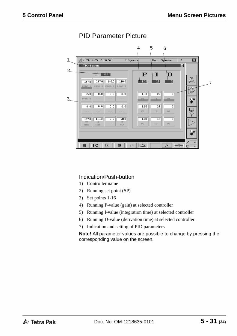
PID Parameter Picture
Indication/Push-button1) Controller name
2) Running set point (SP)
3) Set points 1-16
4) Running P-value (gain) at selected controller
5) Running I-value (integration time) at selected controller
6) Running D-value (derivation time) at selected controller
7) Indication and setting of PID parameters
Note! All parameter values are possible to change by pressing the corresponding value on the screen.
1
2
4 5 6
7
3
5 - 31 (34)Doc. No. OM-1218635-0101

Keyboards 5 Control Panel
KeyboardsDifferent operator commands will bring up different keyboards on the screen.
Integer NumbersThe keyboard in the illustration below will be brought up on the screen if the operator for example wants to choose an integer number.
Floating Point NumbersThe keyboard in the illustration below will be brought up on the screen if the operator for example wants to change a floating point number.
5 - 32 (34) Doc. No. OM-1218635-0101

Keyboards
5 Control Panel
Alphanumerical KeyboardThe keyboard in the illustration below will be brought up on the screen if the user for example wants to log in.
By pressing the key “a-z” (2) the operator brings up the keyboard in the illustration below.
By pressing the key “0-9” (1) the operator brings up the keyboard in the illustration below.
1
2
5 - 33 (34)Doc. No. OM-1218635-0101

Keyboards 5 Control Panel
This page intentionally left blank
5 - 34 (34) Doc. No. OM-1218635-0101

6 Alarm and Troubleshooting
6 - 1 (8)Doc. No. OM-1218635-0101

6 Alarm and Troubleshooting
This page intentionally left blank
6 - 2 (8) Doc. No. OM-1218635-0101

Table of Contents
6 Alarm and Troubleshooting
Indications. . . . . . . . . . . . . . . . . . . . . . . . . . . . . . . . . . . .6 - 5
Alarm Handling . . . . . . . . . . . . . . . . . . . . . . . . . . . . . . . .6 - 5
Fault List . . . . . . . . . . . . . . . . . . . . . . . . . . . . . . . . . . . . .6 - 5
6 - 3 (8)Doc. No. OM-1218635-0101

6 Alarm and Troubleshooting
This page intentionally left blank
6 - 4 (8) Doc. No. OM-1218635-0101

6 Alarm and Troubleshooting
IndicationsWhen a fault occurs, the alarm indication lamp on the control panel and the alarm symbol on the displayed menu will start to flash.
A flashing indication lamp/symbol means an active but not acknowledged alarm.
Steady light indicates an active alarm that has been acknowledged.
CAUTIONAlways investigate the cause of a fault indication. Otherwise you may endanger the equipment.
Alarm HandlingPress the ALARM MENU button to bring up the ALARM LIST to identify the alarm.
Explanation of the alarm list, see chapter control panel.
When the fault has been identified and taken care of press the ACKNOWLEDGE ALARM button.
Fault ListAlarms are divided into two categories as follows:
– A Faults that will cause an alarm only. The faults are not critical but the alarm will make the operator aware of an incident.
– B Faults that will cause action from the PLC, rectify the fault.
6 - 5 (8)Doc. No. OM-1218635-0101

6 Alarm and Troubleshooting
Fault list
Pos Alarm Cause Machine action Instruction to operator
A Aseptic tank(option)
No "ready" signal from Alsafe is present or if “high level” signal from Alsafe is detected.
A Communication fault PLC
Fault in the serial-communication to another process-module
A Outlet temp TE6 fault (option)
Wrong adjustment V26
Adjust V26
A Caustic Feedback from motor M12 or M13 is missing.
Check pump
Check wiring
A Acid Feedback from motor M12 or M13 is missing.
Check pump
Check wiring
A Water pressure Pressure in water circuit to low.
Check incoming water pressure
Check PS66
Check that V66 is open?
A Air pressure in panel
Inlet air pressure to low.
Check incoming air pressure (6 bar)
A Battery fault in PLC
Voltage over the internal CPU battery is low
Change battery
A Filling machine No ready or production signal from filling machine during production
A Disc < 10% Logo screen
Disc full or missing in recorder
Insert/change disc
A Level fault Deaertor vessel
To low or to high level in the Deaerator vessel
A Air cooler in cabinet
Fault in air cooler
A Steam barrier homogeniser (optional)
To low temperature
Check steam pressure to homogeniser
A V62 adjust The plant enters a step where V62 has to be adjusted
Adjust V62
A V63 open The plant enters a step where V63 has to be opened
Open V63
6 - 6 (8) Doc. No. OM-1218635-0101

6 Alarm and Troubleshooting
A V63 close The plant enters a step where V63 can be closed
Close V63
B Temperature transmitter broken
No signal from Temperature transmitter
Not possible to start plant or if running see Temp faults
Check sensor and convertor
B Sterilizing temperature
TT71 indicates a temperature drop during Plant sterilisation.
The program steps down to heating. Check sensor and converter
B Production temperature
TT42 indicates a temperature drop during sterilisation or Production
If in sterilisation the program steps down to heating.
If in production the plant will stop immediately, the product goes to reject.
Check steam supply
Check sensor and converter
B CIP temperature TSL71 indicates a temperature drop during circulation steps in Cleaning
The CIP timer stops and continues from where it was stopped when the alarm is off.
Check steam supply
Check sensor and converter
Check position of V75 (should be in position circulate over BTD)
B Level fault in balance tank
IS65 indicates low level
If low level during Production the program steps to Emptying.
If more than 30 sec. the machine will go to total stop.
Check incoming water
Check pressure (min. 3 bar)
Check auto switches in panel (in auto mode)
Check level switch in BTD
B Motor fault Feedback from a motor is missing.
If the fault is caused from M2 or M5 (option), the plant stops immediately.
If the fault is caused by M9, the steam valve V44 closes.
Pos Alarm Cause Machine action Instruction to operator
6 - 7 (8)Doc. No. OM-1218635-0101

6 Alarm and Troubleshooting
This page intentionally left blank
6 - 8 (8) Doc. No. OM-1218635-0101

7 Preparations
7 - 1 (10)Doc. No. OM-1218635-0101

7 Preparations
This page intentionally left blank
7 - 2 (10) Doc. No. OM-1218635-0101

Table of Contents
7 Preparations
Introduction. . . . . . . . . . . . . . . . . . . . . . . . . . . . . . . . . . .7 - 5
General Checkpoints . . . . . . . . . . . . . . . . . . . . . . . . . . .7 - 6
Checkpoints Holding Tube (Option) . . . . . . . . . . . . . . .7 - 7
Checkpoints Deaerator (Option) . . . . . . . . . . . . . . . . . .7 - 8
7 - 3 (10)Doc. No. OM-1218635-0101

7 Preparations
This page intentionally left blank
7 - 4 (10) Doc. No. OM-1218635-0101

7 Preparations
IntroductionThis chapter contains a list of necessary check points prior to starting the plant. Most points are always to be done, but others are valid only if the corresponding equipment is included in the plant and is going to be used for a certain product. E.g. not all plants include a vacuum chamber and even if so, it might be used only for certain products.
CAUTIONIf product other than specified in Technical Data is processed the sterilisation effect might be insufficient. Other products may need other temperature program.
1Turn the MAIN SWITCH to position ON.
2Turn on the:
• COMPRESSED AIR
• STEAM
• WATER
7 - 5 (10)Doc. No. OM-1218635-0101

7 Preparations
3General Checkpoints• CHECK that the cover is properly
fitted on the balance tank.
• CHECK that the steam switch is in position ON.
• CHECK that all emergency stop buttons are released.
7 - 6 (10) Doc. No. OM-1218635-0101

7 Preparations
4Checkpoints Holding Tube (Option)Make sure that the right holding tube according to the product you are going to run is connected.
A = 4 seconds holding tube
B = 4+26 seconds holding tube (option)
A B
Option
7 - 7 (10)Doc. No. OM-1218635-0101

7 Preparations
5Checkpoints Deaerator (Option)Check the pipe connections
A = Deaerator not connected
B = Deaerator connected
A B
7 - 8 (10) Doc. No. OM-1218635-0101

7 Preparations
6CHECK that the FUNCTION SYMBOL for cleaning indicates that the Therm Aseptic Flex is cleaned, if not start with a cleaning sequence according to chapter OPERATION.
7 - 9 (10)Doc. No. OM-1218635-0101

7 Preparations
This page intentionally left blank
7 - 10 (10) Doc. No. OM-1218635-0101

8 Operation
8 - 1 (34)Doc. No. OM-1218635-0101

8 Operation
This page intentionally left blank
8 - 2 (34) Doc. No. OM-1218635-0101

Table of Contents
8 Operation
Introduction. . . . . . . . . . . . . . . . . . . . . . . . . . . . . . . . . . .8 - 5
Start Sterilising Sequence . . . . . . . . . . . . . . . . . . . . . . .8 - 5
Selection/Settings prior to Start . . . . . . . . . . . . . . . . . .8 - 5
Start Conditions . . . . . . . . . . . . . . . . . . . . . . . . . . . . . . .8 - 7
Start Sequence . . . . . . . . . . . . . . . . . . . . . . . . . . . . . . . .8 - 8
Check during Sequence. . . . . . . . . . . . . . . . . . . . . . . . .8 - 9
Start Production Sequence . . . . . . . . . . . . . . . . . . . . . 8 - 11
Selection/Settings prior to Start . . . . . . . . . . . . . . . . . 8 - 11
Checks prior to Start . . . . . . . . . . . . . . . . . . . . . . . . . .8 - 12
Start Conditions . . . . . . . . . . . . . . . . . . . . . . . . . . . . . .8 - 15
Start Sequence . . . . . . . . . . . . . . . . . . . . . . . . . . . . . . .8 - 16
Checks during Sequence. . . . . . . . . . . . . . . . . . . . . . .8 - 17
Checks during Sequence. . . . . . . . . . . . . . . . . . . . . . .8 - 18
Stop Production Sequence . . . . . . . . . . . . . . . . . . . . .8 - 19
Revert to Sterile Water . . . . . . . . . . . . . . . . . . . . . . . . .8 - 20
Max Time for Sterile Water. . . . . . . . . . . . . . . . . . . . . .8 - 20
Start Stop Sequence. . . . . . . . . . . . . . . . . . . . . . . . . . .8 - 21
Selection/Settings prior to Start . . . . . . . . . . . . . . . . .8 - 21
Start conditions . . . . . . . . . . . . . . . . . . . . . . . . . . . . . .8 - 21
Start Sequence . . . . . . . . . . . . . . . . . . . . . . . . . . . . . . .8 - 22
Emergency Stop . . . . . . . . . . . . . . . . . . . . . . . . . . . . . .8 - 22
After Emergency Stop . . . . . . . . . . . . . . . . . . . . . . . . .8 - 22
Start after Emergency Stop . . . . . . . . . . . . . . . . . . . . .8 - 22
Cleaning. . . . . . . . . . . . . . . . . . . . . . . . . . . . . . . . . . . . .8 - 23
8 - 3 (34)Doc. No. OM-1218635-0101

Table of Contents 8 Operation
Aseptic Intermediate Cleaning -AIC . . . . . . . . . . . . . . 8 - 23
Selection/Settings prior to Start . . . . . . . . . . . . . . . . . 8 - 24
Start Conditions . . . . . . . . . . . . . . . . . . . . . . . . . . . . . . 8 - 24
Start Sequence . . . . . . . . . . . . . . . . . . . . . . . . . . . . . . . 8 - 25
Checks during Sequence . . . . . . . . . . . . . . . . . . . . . . 8 - 26
Final Cleaning- CIP . . . . . . . . . . . . . . . . . . . . . . . . . . . 8 - 27
Selection/Settings prior to Start . . . . . . . . . . . . . . . . . 8 - 27
Start Conditions . . . . . . . . . . . . . . . . . . . . . . . . . . . . . . 8 - 29
Start Sequence . . . . . . . . . . . . . . . . . . . . . . . . . . . . . . . 8 - 30
Checks during Sequence . . . . . . . . . . . . . . . . . . . . . . 8 - 31
Flush . . . . . . . . . . . . . . . . . . . . . . . . . . . . . . . . . . . . . . . 8 - 32
Start Conditions . . . . . . . . . . . . . . . . . . . . . . . . . . . . . . 8 - 32
Start Sequence . . . . . . . . . . . . . . . . . . . . . . . . . . . . . . . 8 - 33
Cleaning of Supply Line . . . . . . . . . . . . . . . . . . . . . . . 8 - 34
8 - 4 (34) Doc. No. OM-1218635-0101

8 Operation
Introduction This chapter describes how to operate the Therm Aseptic Flex in local mode.
Start Sterilising Sequence 1Selection/Settings prior to StartThis selection must fit with the equipment connected. according to chapter preparations.
SELECT desired equipment from the OPERATING MENU:
– If a DEAERATOR is used press a
– If a 30 SECONDS HOLDING CELL is used press b
a b
8 - 5 (34)Doc. No. OM-1218635-0101

8 Operation
2SELECT Product.
(Capacity can be selected/changed at anytime during Sterile Water and Production) (option)
3a) CHECK that valve V76 is in position
DRAIN
b) CHECK that the caustic/acid dosing pipes are connected to the CIP solution drain pipes
V76
DOSING PIPES
8 - 6 (34) Doc. No. OM-1218635-0101

8 Operation
4Start ConditionsPress START CONDITION in the OPERATING MENU.
5All the general and pre-ster. start conditions are fulfilled when the symbols background in the START CHECK MENU are indicated green.
Except from this following conditions must also be fulfilled:
• The PLC in step 0.
• No low level (LSL65) in balance tank
• Air pressure in panel OK
The sterilising sequence can now be started.
Note! The start conditions in the start check menu are described in the chapter CONTROL PANEL.
General start conditions
Pre-ster. start conditions
8 - 7 (34)Doc. No. OM-1218635-0101

8 Operation
6Start SequencePress STERILISATION followed by START in the OPERATION MENU.
– When the sterilising temperature has been reached, the plant will be sterilised for 30 minutes.
– The plant cools down by performing program steps Cooling 1-3 and Stabilising.
– When the plant is cooled down, Sterile water is indicated on the display.
8 - 8 (34) Doc. No. OM-1218635-0101

8 Operation
7Check during Sequence
7 a
a) CHECK pressure at P07 (4 bar) if HTP (high temperature products) is to be produced
b) CHECK that the temperature (TE1) before the homogeniser is 85°C, adjust with V63.
V63
8 - 9 (34)Doc. No. OM-1218635-0101

8 Operation
7 b
Option Deaerator
CHECK the water supply for the seals on the vacuum pump M11 and the pump M5 on the deaerator.
ADJUST the vacuum and the cooling water by means of valves V30/V33 until a temperature difference of 4 °C is achieved.
8Continue with desired sequence:
PRODUCTION: See “Start Production Sequence” on page 8-11.
AIC: See “Aseptic Intermediate Cleaning -AIC” on page 8-23.
CIP: See “Final Cleaning- CIP” on page 8-27.
STOP: See “Start Stop Sequence” on page 8-21.
VAC. ATM.
GF200830
8 - 10 (34) Doc. No. OM-1218635-0101

8 Operation
Start Production Sequence
Selection/Settings prior to Start1a) Press desired push button 1 - 4 in the
AFM/CAPACITY MENU to select the aseptic filling machine or capacity for production.
Note! Can be selected at any time during Sterile Water and Production. The change over sequence will take approx. 2 -5 min.
Option:
b) Press TANK SYMBOL for production to Tetra Alsafe tank.
8 - 11 (34)Doc. No. OM-1218635-0101

8 Operation
2Checks prior to Start
2 aCheck that the flow at FI66 is enough to match the chosen capacity, adjust if necessary with the valve V62.
V62
FI66
8 - 12 (34) Doc. No. OM-1218635-0101

8 Operation
2 ba) CHECK that V15.1 (CIP return) is
closed
b) Open the valve V15.2 towards the drain
3Press PRODUCT SUPPLY PUMP followed by START in the OPERATION MENU.
V15.1 V15.2
8 - 13 (34)Doc. No. OM-1218635-0101

8 Operation
4a) CLOSE valve V 15.2 when product
is visible at the drain outlet.
5Stop the product supply pump by pressing PROD SUPPLY followed by STOP.
V15.2
8 - 14 (34) Doc. No. OM-1218635-0101

8 Operation
6a) CHECK that the valve V76 is in
correct position, towards the reject tank (or drain) to continue pushing out the product to reclaim tank (or drain)
b) CHECK that the caustic/acid dosing pipes are connected to the cip solution drain pipes
7Start Conditions
1 Ready indication AFM/Alsafe2 No alarms
V76
DOSING PIPES
1
2
8 - 15 (34)Doc. No. OM-1218635-0101

8 Operation
8Start SequencePress PRODUCTION followed by START in the OPERATION MENU.
The first filling step is the prepare production step, which means that cold water enters the plant to bring down the filling temperature.
When the filling temperature (TT71) has dropped to a preset temperature or a timer has elapsed, Filling is indicated on the display.
The plant will now automatically drain the water from the balance tank, activate V13. and start the product supply pump.
A timer controls when the product line contains product only, valve V75 reroutes the flow to the balance tank for recirculation.
The plant is ready for production. Signal is given to the filling machines.
Note! If a disturbance occurs during Production, the Therm Aseptic Flex will automatically proceed to Emptying and end up in Sterile water or Parking position.
If a permanent or longer stop at a filling machine occurs, it is possible to revert
to Sterile water. See “Revert to Sterile Water” on page 8-20.
Reverting to this phase, sterile water displaces the product.
8 - 16 (34) Doc. No. OM-1218635-0101

8 Operation
9Checks during Sequence
9 aRegular check on the process values such as flow, temperature and pressure.
Recommended max time for production
During operation deposits may build up on the heat exchanger surfaces and in the product holding cell.
• Check the pressure drop over the heat exchanger
– if the pressure drop is too big, production must be stopped and cleaning has to be done
– max pressure after the homogeniser/booster pump is stated on the machine sign.
• Check the temperature difference between the heating medium and the product.
– max temperature is stated on the machine sign.
8 - 17 (34)Doc. No. OM-1218635-0101

8 Operation
9 bOption extra cooler
CHECK that the correct filling temperature TT6 in maintained, adjust with valve V26.
9 cChecks during SequenceOption Deaertor
ADJUST the vacuum and the cooling water by means of valves V30/V33 until a temperature difference of 4 °C is achieved.
V26
VAC. ATM.
GF200830
8 - 18 (34) Doc. No. OM-1218635-0101

8 Operation
Stop Production SequenceSelect one of the following to stop the production.
• STERILE WATER: See “Revert to Sterile Water” on page 8-20.
• AIC: See “Aseptic Intermediate Cleaning -AIC” on page 8-23.
• CIP: See “Final Cleaning- CIP” on page 8-27.
• STOP: See “Start Stop Sequence” on page 8-21.
Note! Select CIP directly after finished production.
8 - 19 (34)Doc. No. OM-1218635-0101

8 Operation
Revert to Sterile WaterInstead of continuing to circulate the product during any kind of disturbance, the plant can be reverted to Sterile water.
Press STERILISING followed by START in the OPERATION MENU.
The plant will now automatically:
• drain the product from the balance tank to reject or drain (V75 deactivated).
• deactivate V13.
• stop AFM before product/water mix reaches AFM (timer controlled).
Max Time for Sterile Water There is a limit for how long time the Therm Aseptic Flex may run in Sterile Water before cleaning is required.
It depends on the milk temperature in the supply pipe to the balance tank. At a temperature of 15 °C the milk can stand about 6 hours before it is destroyed and the Therm Aseptic Flex unit has to be cleaned and resterilised.
8 - 20 (34) Doc. No. OM-1218635-0101

8 Operation
Start Stop Sequence 1Can be ordered from all programme steps except for CIP/AIC.
If ordered from Production, an emptying and a rinse sequence take place automatically before the Stop-sequence starts.
The plant will end in Parking position.
Selection/Settings prior to Start• Nothing stated
2Start conditions• No alarms
• If selected from PRODUCTION. CHECK that the valve V76 is in correct position, towards the reject tank (or drain) to continue pushing out the product to reclaim tank (or drain)
V76
8 - 21 (34)Doc. No. OM-1218635-0101

8 Operation
3Start SequencePress STOP followed by START in the OPERATION MENU.
The balance tank is drained and a cold water rinse sequence is started. The cooling down and the Therm Aseptic Flex is ended up in Parking position.
Emergency StopPress the emergency stop button on the control panel to stop the plant immediately. All pumps will stop and all valves will be deactivated.
WARNINGEmergency stopped The machine may contain hot liquid or cleaning solution. Handle wit outmost care to avoid exposure.
After Emergency StopAfter emergency stop has been activated, the sterile temperature (TT42) will drop below set point.
Start after Emergency Stop• Release all emergency stops.
• Reset the homogeniser on the Tetra Alex control panel.
The Therm Aseptic Flex must be emptied by means of the FLUSH. See “Flush” on page 8-32.
Note! CIP must be ordered if product has entered the plant.
8 - 22 (34) Doc. No. OM-1218635-0101

8 Operation
CleaningCleaning is carried out in the following sequences:
• Aseptic Intermediate Cleaning - AIC
• Final Cleaning - CIP
• Flush
• Cleaning of Supply Line
CAUTIONThe cleaning program is designed for the products specified in the Technical Data. If any other product is processed, the cleaning result might be insufficient. Other products may need new CIP program setup.
Aseptic Intermediate Cleaning -AIC AIC can be ordered to extend the production period before a full cleaning, CIP, is required.
The AIC takes approximately 40 minutes. The plant remains sterile in its aseptic part.
WARNINGChemical hazard Cleaning solution contains Caustic soda (NaOH) or Nitric acid (HNO3). These chemicals may cause severe burning to skin and eyes. Use protective clothes, goggles and gloves during handling. If exposed - wash with water for at least 15 minutes. Seek medical assistance. Follow the instructions given by the supplier.
8 - 23 (34)Doc. No. OM-1218635-0101

8 Operation
1Selection/Settings prior to Starta) CONNECT the caustic/acid dosing
pipes to the balance tank
b) CHECK that valve V76 is in position drain
2Start Conditions
2 aPress START CONDITION in the OPERATING MENU.
V76
DOSINGPIPES
8 - 24 (34) Doc. No. OM-1218635-0101

8 Operation
2 b• From STERILE WATER: CIP
dosing pipes connected to balance tank and No alarms
3Start Sequencea) Select appropriate AIC followed by
START within 15 seconds.
If AIC is ordered from programme step Production, an emptying and a rinse sequence take place automatically before the intermediate cleaning starts.
When the cleaning is completed, the indication for AIC goes out and STERILE WATER is indicated with green.
8 - 25 (34)Doc. No. OM-1218635-0101

8 Operation
4Checks during SequenceCHECK that the flow at FI66 is enough to match the chosen capacity, adjust if necessary with the valve v62.
V62
FI66
8 - 26 (34) Doc. No. OM-1218635-0101

8 Operation
Final Cleaning- CIPSelect CIP directly after finished production.
The CIP takes approximately 120 minutes. The plant remains sterile in its aseptic part.
1Selection/Settings prior to Start
1 aa) CONNECT the caustic/acid dosing
pipes to the balance tank
b) CHECK that valve V76 is in position drain
WARNINGChemical hazard Cleaning solution contains Caustic soda (NaOH) or Nitric acid (HNO3). These chemicals may cause severe burning to skin and eyes. Use protective clothes, goggles and gloves during handling. If exposed - wash with water for at least 15 minutes. Seek medical assistance. Follow the instructions given by the supplier.
V76
DOSINGPIPES
8 - 27 (34)Doc. No. OM-1218635-0101

8 Operation
1 ba) OPEN the valve v62 fully.
V62
8 - 28 (34) Doc. No. OM-1218635-0101

8 Operation
2Start Conditions
2 aPress START CONDITION in the OPERATING MENU.
8 - 29 (34)Doc. No. OM-1218635-0101

8 Operation
2 b• From Parking position: all general
and CIP start conditions fulfilled.
• From Sterile water: CIP dosing pipes connected to balance tank
3Start Sequencea) Select appropriate CIP followed by
START within 15 seconds.
– The CIP function is indicated with white.
When the cleaning is completed, the indication for CIP goes off and the plant stops.
General start conditions
CIP start conditions
8 - 30 (34) Doc. No. OM-1218635-0101

8 Operation
4Checks during Sequencea) During STEP 114
OPEN the valve v63 to avoid boiling in the BTD.
V63
8 - 31 (34)Doc. No. OM-1218635-0101

8 Operation
Flush The FLUSH FUNCTION is only selectabled from Parking position.
Use the Flush function to:
– flush out the product.
– emptying after an emergency stop.
to cool down the equipment.
1Start Conditions
1 aPress START CONDITION in the OPERATING MENU
1 bIn Parking position: all general start conditions fulfilled.
8 - 32 (34) Doc. No. OM-1218635-0101

8 Operation
2Start SequencePress FLUSH followed by START in the OPERATION MENU.
8 - 33 (34)Doc. No. OM-1218635-0101

8 Operation
Cleaning of Supply Line The cleaning is controlled by an external CIP-system.
a) OPEN the valve V15:1 towards cip return
b) OPEN (Flip) the valve V15:2 for a short while towards drain during circulation
Note! The pipes connected to the Valve V15:2 can easily be removed for manually cleaning.
V15:1V15:2
8 - 34 (34) Doc. No. OM-1218635-0101

9 Care and Cleaning
9 - 1 (6)Doc. No. OM-1218635-0101

9 Care and Cleaning
This page intentionally left blank
9 - 2 (6) Doc. No. OM-1218635-0101

Table of Contents
9 Care and Cleaning
Verify Cleaning. . . . . . . . . . . . . . . . . . . . . . . . . . . 9 - 5
Daily Check. . . . . . . . . . . . . . . . . . . . . . . . . . . . . . . 9 - 5
Cleaning Complete . . . . . . . . . . . . . . . . . . . . . . . . . 9 - 5
Lye/Acid Concentration. . . . . . . . . . . . . . . . . . . . . . 9 - 5
Homogenizer damper . . . . . . . . . . . . . . . . . . . . . . . 9 - 5
Recommended Check . . . . . . . . . . . . . . . . . . . . . . 9 - 5
Holding cell . . . . . . . . . . . . . . . . . . . . . . . . . . . . . . . 9 - 5
9 - 3 (6)Doc. No. OM-1218635-0101

9 Care and Cleaning
This page intentionally left blank
9 - 4 (6) Doc. No. OM-1218635-0101

9 Care and Cleaning Verify Cleaning
Verify Cleaning
Daily CheckCleaning CompleteCheck on the recorder that the cleaning has run the appropriate time with the appropriate temperatures.
Lye/Acid ConcentrationCheck that the lye and acid concentrations during cleaning are appropriate.
Homogenizer damperDisassemble the homogenizer damper to ensure an air cushion inside and:
• check that it is free from any product residues after cleaning.
• clean the damper manually if necessary.
Recommended CheckIt is recommended to regularly weekly/monthly verify the cleaning result at critical points such as the holding cell.
Holding cell Disassemble the holding cell or holding cells (if applicable) and:
• visually check that it is free from any product residues after cleaning
• make a swab test to check that the cleaning result is appropriate
• if necessary, adjust cleaning circulation time and detergent concentration
9 - 5 (6)Doc. No. OM-1218635-0101

Verify Cleaning 9 Care and Cleaning
This page intentionally left blank
9 - 6 (6) Doc. No. OM-1218635-0101


This page intentionally left blank