Embed Size (px)
Citation preview

O&M - RAILOK
Roof Edge Fabrications Railok
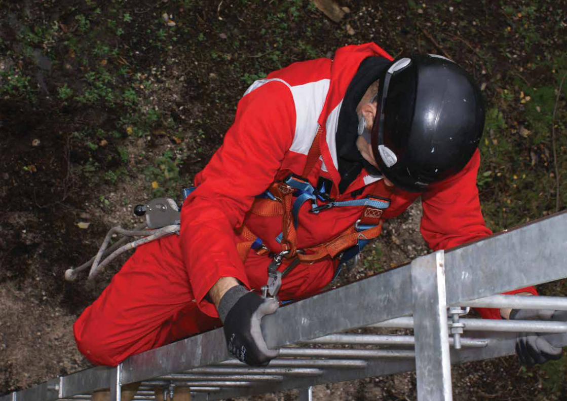
INTRODUCTIONMasts, gantries, ladders, silos etc often need to be accessed for maintenance purposes. Many of the ladders used to access these structures depend upon hoops to protect the operatives, however in many instances these can cause severe injuries and in some cases fatalities. Railok has been developed in order to overcome these problems and to ensure operative safety and protection from potential falls. The system allows the operative to ascend/descend uninhibited, but, if they were to fall whilst attached to the system, the fall would be arrested and the operative would then merely adjust their footing and continue to ascend/descend normally.
SPECIFICATIONRailok is a rigid vertical safety system consisting of an extruded alloy section and a flat Stainless Steel rail. The system is fixed using universal mounting brackets which enable connection to any rung profile or size from 12mm to 50mm or any stringer profile or size to a maximum of 100 x 50mm.
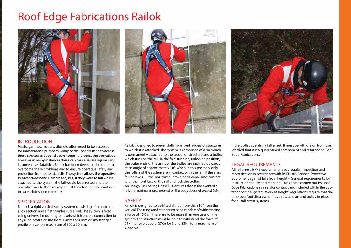
Railok is designed to prevent falls from fixed ladders or structures to which it is attached. The system is comprised of a rail which is permanently attached to the ladder or structure and a trolley which runs on the rail. In the free-running, unlocked position, the outer ends of the arms of the trolley are inclined upwards at an angle of approximately 10°. When in this position, only the rollers of the system are in contact with the rail. If the arms fall below 10°, the horizontal brake pads come into contact with the front face of the rail and lock the trolley.An Energy Dissipating Unit (EDU) ensures that in the event of a fall, the maximum force exerted on the body does not exceed 6kN.
SAFETYRailok is designed to be fitted at not more than 10° from the vertical. The rungs and stringer must be capable of withstanding a force of 15Kn. If there are to be more than one user on the system, the structure must be able to withstand the force of 21Kn for two people, 27Kn for 3 and 33Kn for a maximum of 4 people.
If the trolley sustains a fall arrest, it must be withdrawn from use, labelled that it is a quarantined component and returned to Roof Edge Fabrications.
LEGAL REQUIREMENTSAll fall arrest & PPE equipment needs regular inspection and recertification in accordance with BS EN 365 Personal Protective Equipment against falls from height – General requirements for instruction for use and marking. This can be carried out by Roof Edge Fabrications as a service contract and included within the quo-tation for the System. Work at Height Regulations require that the employer/building owner has a rescue plan and policy in place for all fall arrest systems.
Roof Edge Fabrications Railok Specification - BS EN 353-1
PRODUCT SPECIFICATION
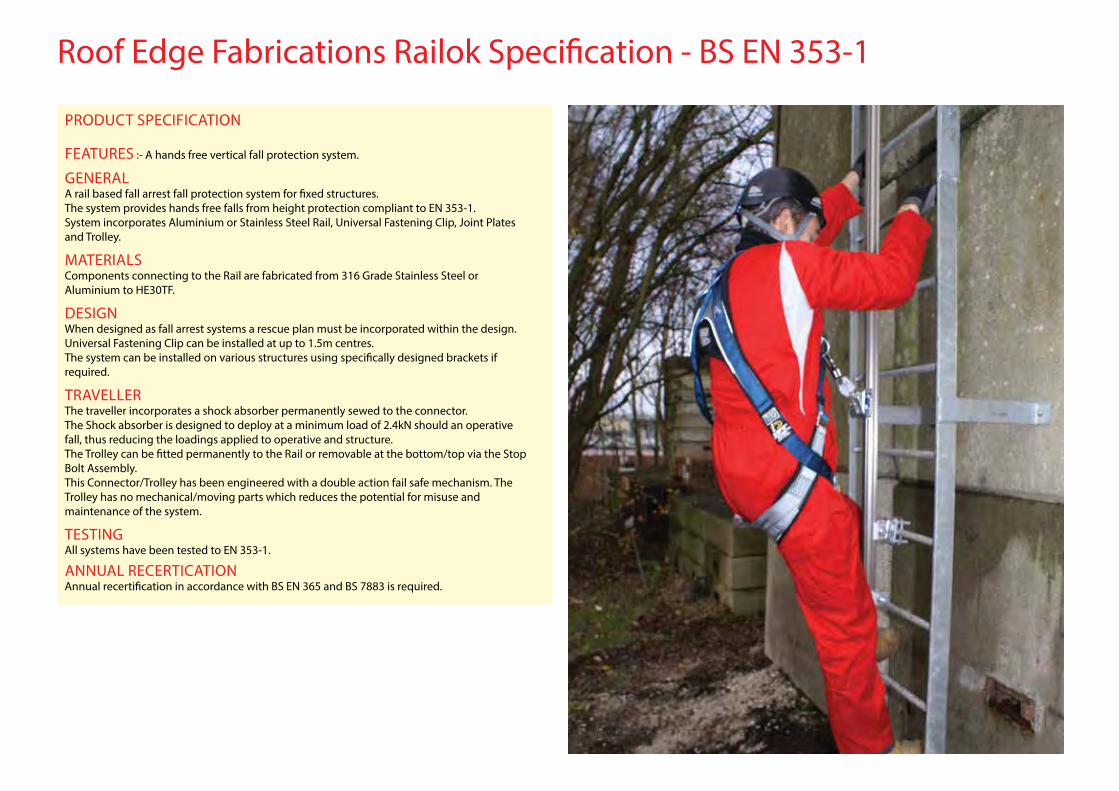
FEATURES :- A hands free vertical fall protection system.
GENERALA rail based fall arrest fall protection system for fixed structures.The system provides hands free falls from height protection compliant to EN 353-1.System incorporates Aluminium or Stainless Steel Rail, Universal Fastening Clip, Joint Plates and Trolley.
MATERIALSComponents connecting to the Rail are fabricated from 316 Grade Stainless Steel orAluminium to HE30TF.
DESIGNWhen designed as fall arrest systems a rescue plan must be incorporated within the design.Universal Fastening Clip can be installed at up to 1.5m centres.The system can be installed on various structures using specifically designed brackets if required.
TRAVELLERThe traveller incorporates a shock absorber permanently sewed to the connector.The Shock absorber is designed to deploy at a minimum load of 2.4kN should an operative fall, thus reducing the loadings applied to operative and structure.The Trolley can be fitted permanently to the Rail or removable at the bottom/top via the Stop Bolt Assembly.This Connector/Trolley has been engineered with a double action fail safe mechanism. The Trolley has no mechanical/moving parts which reduces the potential for misuse andmaintenance of the system.
TESTINGAll systems have been tested to EN 353-1.
ANNUAL RECERTICATIONAnnual recertification in accordance with BS EN 365 and BS 7883 is required.
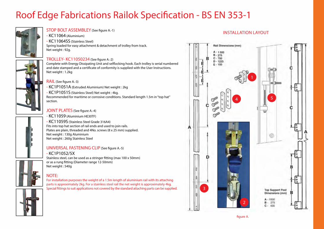
Roof Edge Fabrications Railok Specification - BS EN 353-1STOP BOLT ASSEMBLEY (See figure A.-1)
- KC11064 (Aluminium)
- KC11064SS (Stainless Steel)Spring loaded for easy attachment & detachment of trolley from track.Net weight : 92g.
TROLLEY- KC11050234 (See figure A.-2)Complete with Energy Dissipating Unit and selflocking hook. Each trolley is serial numbered and date stamped and a certificate of conformity is supplied with the User Instructions.Net weight : 1.2kg
RAIL (See figure A.-3)
- KC1P1051A (Extruded Aluminium) Net weight : 2kg
- KC1P1051S (Stainless Steel) Net weight : 4kg.Recommended for maritime or corrosive conditions. Standard length 1.5m in “top hat” section.
JOINT PLATES (See figure A.-4)
- KC11059 (Aluminium HE30TF)
- KC11059S (Stainless Steel Grade 316A4)Fits into top hat section of rail ends and used to join rails.Plates are plain, threaded and 4No. screws (8 x 25 mm) supplied.Net weight : 130g AluminiumNet weight : 260g Stainless Steel
UNIVERSAL FASTENING CLIP (See figure A.-5)
- KC1P1052/5XStainless steel, can be used as a stringer fitting (max 100 x 50mm)or as a rung fitting (Diameter range 12-50mm)Net weight : 540g
NOTE:For installation purposes the weight of a 1.5m length of aluminium rail with its attaching parts is approximately 2kg. For a stainless steel rail the net weight is approximately 4kg.Special fittings to suit applications not covered by the standard attaching parts can be supplied.
INSTALLATION LAYOUT
figure A.
1
3
4 5
2
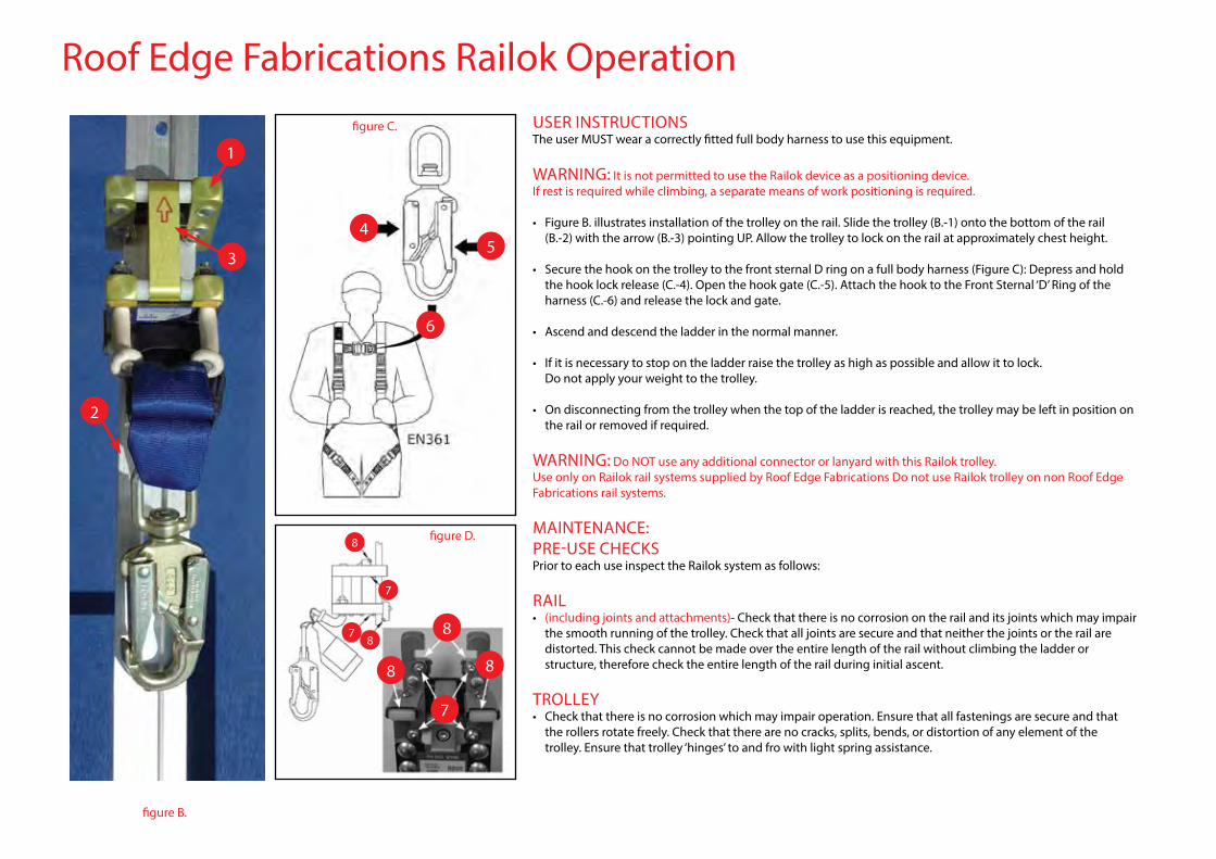
Roof Edge Fabrications Railok OperationUSER INSTRUCTIONSThe user MUST wear a correctly fitted full body harness to use this equipment.
WARNING: It is not permitted to use the Railok device as a positioning device.If rest is required while climbing, a separate means of work positioning is required.
• Figure B. illustrates installation of the trolley on the rail. Slide the trolley (B.-1) onto the bottom of the rail (B.-2) with the arrow (B.-3) pointing UP. Allow the trolley to lock on the rail at approximately chest height.
• Secure the hook on the trolley to the front sternal D ring on a full body harness (Figure C): Depress and hold the hook lock release (C.-4). Open the hook gate (C.-5). Attach the hook to the Front Sternal ‘D’ Ring of the harness (C.-6) and release the lock and gate.
• Ascend and descend the ladder in the normal manner.
• If it is necessary to stop on the ladder raise the trolley as high as possible and allow it to lock. Do not apply your weight to the trolley.
• On disconnecting from the trolley when the top of the ladder is reached, the trolley may be left in position on the rail or removed if required.
WARNING: Do NOT use any additional connector or lanyard with this Railok trolley.Use only on Railok rail systems supplied by Roof Edge Fabrications Do not use Railok trolley on non Roof Edge Fabrications rail systems.
MAINTENANCE:PRE-USE CHECKSPrior to each use inspect the Railok system as follows:
RAIL• (including joints and attachments)- Check that there is no corrosion on the rail and its joints which may impair the smooth running of the trolley. Check that all joints are secure and that neither the joints or the rail are distorted. This check cannot be made over the entire length of the rail without climbing the ladder or structure, therefore check the entire length of the rail during initial ascent.
TROLLEY • Check that there is no corrosion which may impair operation. Ensure that all fastenings are secure and that the rollers rotate freely. Check that there are no cracks, splits, bends, or distortion of any element of the trolley. Ensure that trolley ‘hinges’ to and fro with light spring assistance.
2
3
1
figure B.
figure D.
figure C.
45
8
8
7
78
8 8
7
6
Roof Edge Fabrications Railok Recertification• Periodic inspections by a competent person are required under Regulation 5 of the Workplace (Health Safety & Welfare) Regulations, BS EN 365 & BS 7883.
• The frequency will depend upon environment, location and utilisation, but should be at least every 12 months.
• Check structural connection of system.
• Climb the complete system and check the intermediate brackets for wear & tear. Check the system still serves the client’s needs.
• Establish if any modifications or additional products are required to reflect any refurbishment or additional plant and equipment that has been installed and requires access.
TROLLEY INSPECTION • Holding the trolley on its side pivot the top plate forward. Release it and ensure that it pivots fully rearwards with light spring assistance.• Ensure the four brake ‘discs’ (figure D. -7) are in place and correctly positioned.• Check that all rollers rotate freely (figure D. -8).• Ensure that the rivets attaching the plates to the upper and lower arms are secure by attempting to pull the arms apart. No movement of the arms is permissible.• With the trolley in position on the rail ensure that it will move upward freely when lifted by the EDU snap hook and that it locks on the rail when the hook is released.• Ensure that the trolley moves freely over each rail joint.• Clean with a cloth and warm soapy water. DO NOT IMMERSE. Lubricate rollers with water repellent oil (e.g. WD40). Wipe off excess oil.• Check that the EDU ‘D’ ring locknuts are secure.• Check that the EDU ‘D’ ring rubber sleeves are in place and sound condition.• Check that the outer sleeve of EDU is correctly positioned and in good condition and that no webbing has been pulled from the sleeve or stitching torn.• Check that the webbing at the ‘D’ ring and snap hook is sound.• Check the snap hook for corrosion and ensure that the locking mechanism functions correctly. Check that the hook pivots freely on its attachment ring.• Any major components i.e. other than nuts/ bolts/ washers etc which may need replacing report to client and establish costing so it can be repaired whilst on site, if possible.• Check system plaque position & mark up to reflect date of the next required inspection. Establish if additional plaques are required due to any refurbishment works.
RAIL INSPECTION• Inspect rail for damage/splits/cracks and any signs of wear/missing fixings/bending/distortion. If distortion is evident it is indicative that the rail may have been subjected to a fall arrest load. In the event of this the rail, adjoining rails and all fixings including joining plates must be replaced. • Check and tighten all visible / accessible fixings. Check stop bolt operation where fitted.• Check for any components showing signs of corrosion or electrolytic action/effects.• If corrosion is significant take digital photographs and include in the inspection report.• Pull test visible end fixings to concrete / brickwork / structure (where possible) 6kN - 15 secs.• Clean entire track with a fibre (NOT WIRE) brush or “scotchbrite”.• Any part of the installation or fixings that may need additional attention - take digital photographs and include in inspection report.
NOTES• Check rail orientation with respect to the rungs or stringers.• All torque settings of the cap headed screws, clamp-plate screws and nuts (25Nm),• Tightness of the adjuster lock-nuts (25Nm).• The trolley passes each universal bracket assembly.• If any component of the universal bracket is damaged the complete assembly should be replaced.
WARNING• If the trolley sustains a fall arrest it MUST be withdrawn from service immediately, labelled to indicate it is a quarantined component and returned to Roof Edge Fabrications Limited together with a note indicating the nature and circumstances of the fall.
INTRODUCTIONEmployers have a duty under the Health & Safety at Work etc Act toprovide a safe means of access and egress to the workplace. There isalso an obligation to ensure that work equipment is safe, properlyinstalled and maintained.Additional guidance on fixed ladders can be found in BS4211 whichspecifies the requirements for ladders with single bar rungs which arefixed permanently to structures to provide a means of access. Thisincludes usage on high structures such as chimneys, silos and bins.
MAINTENANCE & RECERTIFICATIONEach time a ladder is used, a visual inspection must be carried out by acompetent person to check for wear and abrasion. Regular checks tocertify that the fittings, hinges, anchor points, supports and mountingpoints are rigid and stable enough to ensure the safety of users mustalso be carried out.
Periodic inspections by a competent person are required underRegulation 5 of the Workplace (Health, Safety & Welfare) Regulations,the Work at Height Regulations 2005 and BS 4211.
When inspecting or recertifying a ladder, a risk rating must be deter-mined by considering its physical compliance and factors such as light-ing levels, environment, housekeeping, proximity of adjacent servicesetc.
FALL PROTECTIONFall protection must be provided when the ladders is more than 2m highor if there is a risk of falling more than 2m, for example if there is anunprotected side to the access platform (or similar structure) or if radiusfrom the centreline of the ladder is less than 3m.
For new installations a risk assessment must be carried out whenconsidering the removal of traditional hoops and installation of avertical fall arrest solution. The height of the ladder, frequency of use,level of training and availability of PPE will need to be considered.In instances where a ladder is fitted with both hoops and a vertical fallarrest system the responsible person will need to contact themanufacturer to establish the suitability of this combination. During therecertification process this needs to be addressed.
Fall arrest systems should be fitted in accordance with BS EN 363 . Ifa guided type of fall arrester is fitted then this must be in accordancewith BS EN 353-1 or BS EN 353-2.
Any unauthorised access must be prevented through the use of suitablesafeguards such as locking devices.
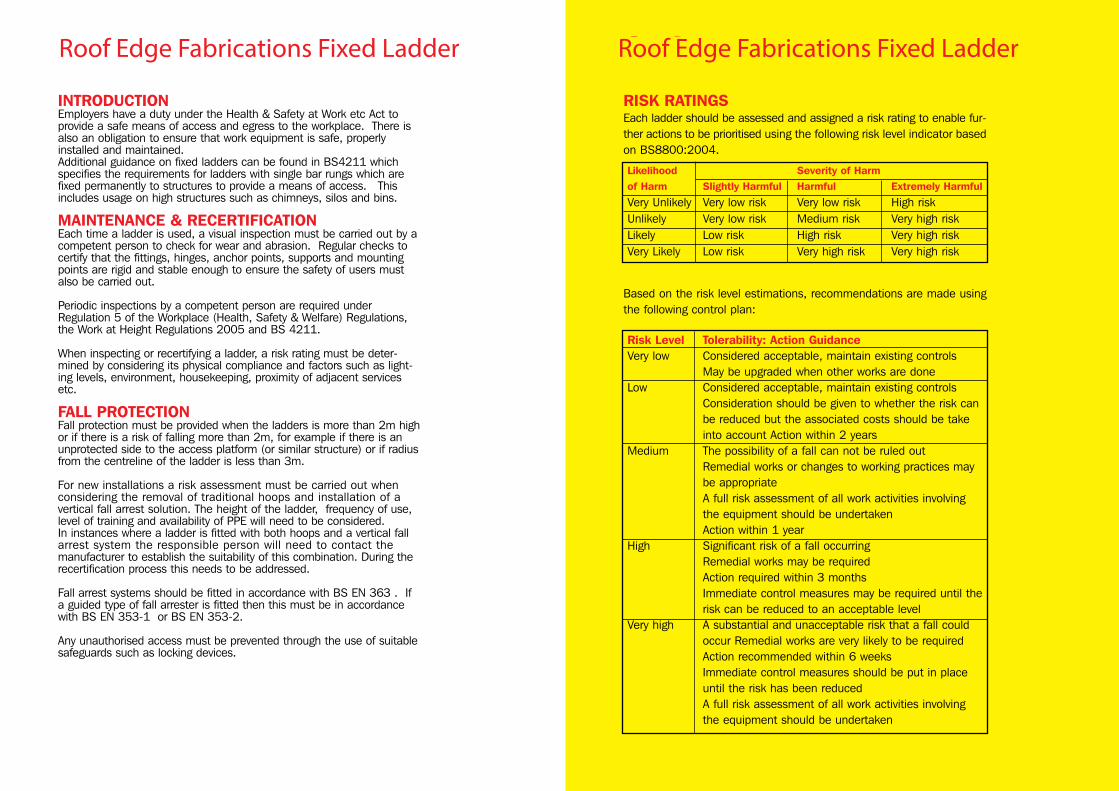
Safesite Fixed Ladder Safesite Fixed LadderRISK RATINGSEach ladder should be assessed and assigned a risk rating to enable fur-ther actions to be prioritised using the following risk level indicator basedon BS8800:2004.
Based on the risk level estimations, recommendations are made usingthe following control plan:
Likelihood Severity of Harmof Harm Slightly Harmful Harmful Extremely Harmful
Very Unlikely Very low risk Very low risk High riskUnlikely Very low risk Medium risk Very high riskLikely Low risk High risk Very high riskVery Likely Low risk Very high risk Very high risk
Risk Level Tolerability: Action GuidanceVery low Considered acceptable, maintain existing controls
May be upgraded when other works are doneLow Considered acceptable, maintain existing controls
Consideration should be given to whether the risk canbe reduced but the associated costs should be takeinto account Action within 2 years
Medium The possibility of a fall can not be ruled outRemedial works or changes to working practices maybe appropriateA full risk assessment of all work activities involvingthe equipment should be undertakenAction within 1 year
High Significant risk of a fall occurringRemedial works may be requiredAction required within 3 monthsImmediate control measures may be required until therisk can be reduced to an acceptable level
Very high A substantial and unacceptable risk that a fall couldoccur Remedial works are very likely to be requiredAction recommended within 6 weeksImmediate control measures should be put in placeuntil the risk has been reducedA full risk assessment of all work activities involvingthe equipment should be undertaken
Safesite_O&M_pages changed???!!!:brochure 28/3/13 10:58 Page 78
COMPLIANCE CRITERIAAs stipulated in the Workplace (Health, Safety and Welfare) Regulations, ACOP andBS4211, the following principle criteria should be used when assessing the complianceof each ladder.
• Fixed ladders should not be used where it would be practical to install aconventional staircase
• The ladder should be of sound construction, properly maintained and securelyfixed
• Assembly should be sufficiently rigid and stable to ensure safety of the userunder normal conditions
• Handrails should extend at least 1100mm above landing• Stiles should extend to the height of guarding• The ladder should not exceed 6m without an intermediate landing• Hoops should be fixed if the ladder exceeds 2.5m• Fall protection should be provided if there is a risk of falling more than 2m• Hoops should be a maximum of 900mm apart• Hoops should not exceed 1500m apart with uprights not more than 300mm
apart• The width between the strings should be between 300mm (400mm preferred)
and 600mm• Handrails should open out to between 600mm & 700mm above the landing• Rungs must withstand 1.5kN and have a diameter of 20-35 mm• The top rung should be level with the platform• Rise between rungs should be 225mm to 300mm• A minimum of 200mm clear space should be behind each rung• Clear space on the user side should be 600mm
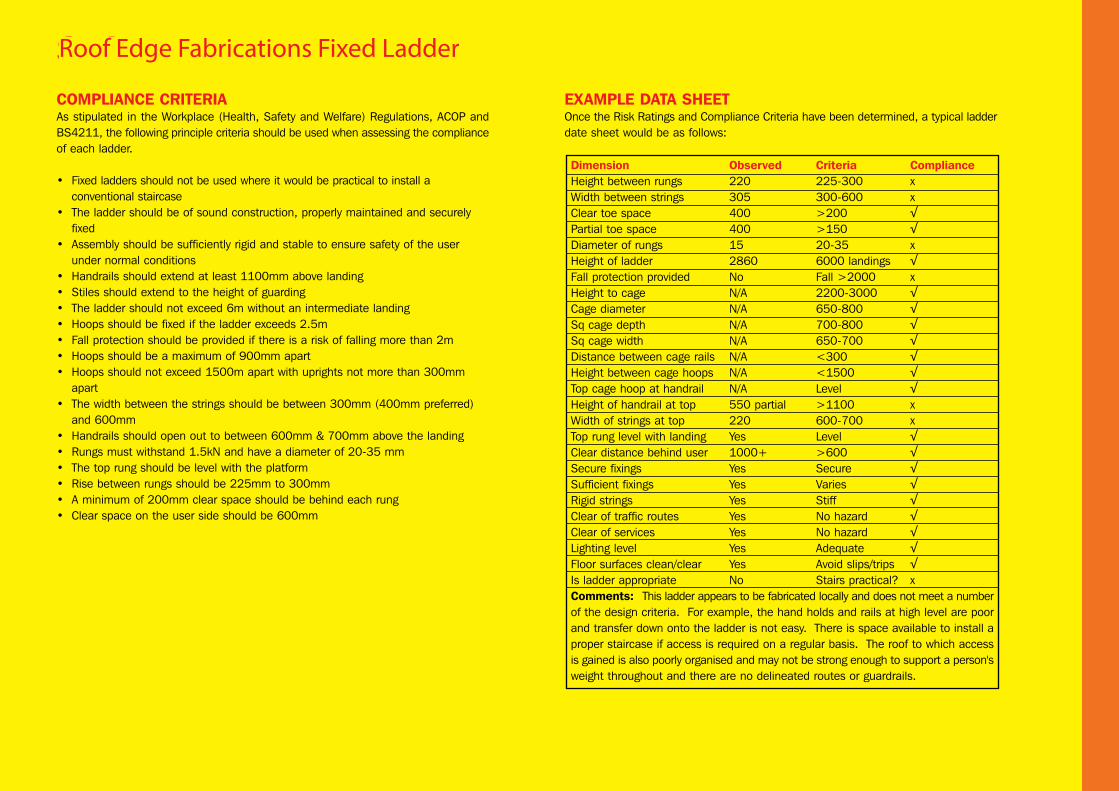
EXAMPLE DATA SHEETOnce the Risk Ratings and Compliance Criteria have been determined, a typical ladderdate sheet would be as follows:
Safesite Fixed Ladder
Dimension Observed Criteria ComplianceHeight between rungs 220 225-300 xWidth between strings 305 300-600 xClear toe space 400 >200 √Partial toe space 400 >150 √Diameter of rungs 15 20-35 xHeight of ladder 2860 6000 landings √Fall protection provided No Fall >2000 xHeight to cage N/A 2200-3000 √Cage diameter N/A 650-800 √Sq cage depth N/A 700-800 √Sq cage width N/A 650-700 √Distance between cage rails N/A <300 √Height between cage hoops N/A <1500 √Top cage hoop at handrail N/A Level √Height of handrail at top 550 partial >1100 xWidth of strings at top 220 600-700 xTop rung level with landing Yes Level √Clear distance behind user 1000+ >600 √Secure fixings Yes Secure √Sufficient fixings Yes Varies √Rigid strings Yes Stiff √Clear of traffic routes Yes No hazard √Clear of services Yes No hazard √Lighting level Yes Adequate √Floor surfaces clean/clear Yes Avoid slips/trips √Is ladder appropriate No Stairs practical? xComments: This ladder appears to be fabricated locally and does not meet a numberof the design criteria. For example, the hand holds and rails at high level are poorand transfer down onto the ladder is not easy. There is space available to install aproper staircase if access is required on a regular basis. The roof to which accessis gained is also poorly organised and may not be strong enough to support a person'sweight throughout and there are no delineated routes or guardrails.
Safesite_O&M_pages changed???!!!:brochure 28/3/13 10:58 Page 79
Roof Edge Fabrications Fixed Ladder Roof Edge Fabrications Fixed Ladder
COMPLIANCE CRITERIAAs stipulated in the Workplace (Health, Safety and Welfare) Regulations, ACOP andBS4211, the following principle criteria should be used when assessing the complianceof each ladder.
• Fixed ladders should not be used where it would be practical to install aconventional staircase
• The ladder should be of sound construction, properly maintained and securelyfixed
• Assembly should be sufficiently rigid and stable to ensure safety of the userunder normal conditions
• Handrails should extend at least 1100mm above landing• Stiles should extend to the height of guarding• The ladder should not exceed 6m without an intermediate landing• Hoops should be fixed if the ladder exceeds 2.5m• Fall protection should be provided if there is a risk of falling more than 2m• Hoops should be a maximum of 900mm apart• Hoops should not exceed 1500m apart with uprights not more than 300mm
apart• The width between the strings should be between 300mm (400mm preferred)
and 600mm• Handrails should open out to between 600mm & 700mm above the landing• Rungs must withstand 1.5kN and have a diameter of 20-35 mm• The top rung should be level with the platform• Rise between rungs should be 225mm to 300mm• A minimum of 200mm clear space should be behind each rung• Clear space on the user side should be 600mm
EXAMPLE DATA SHEETOnce the Risk Ratings and Compliance Criteria have been determined, a typical ladderdate sheet would be as follows:
Safesite Fixed Ladder
Dimension Observed Criteria ComplianceHeight between rungs 220 225-300 xWidth between strings 305 300-600 xClear toe space 400 >200 √Partial toe space 400 >150 √Diameter of rungs 15 20-35 xHeight of ladder 2860 6000 landings √Fall protection provided No Fall >2000 xHeight to cage N/A 2200-3000 √Cage diameter N/A 650-800 √Sq cage depth N/A 700-800 √Sq cage width N/A 650-700 √Distance between cage rails N/A <300 √Height between cage hoops N/A <1500 √Top cage hoop at handrail N/A Level √Height of handrail at top 550 partial >1100 xWidth of strings at top 220 600-700 xTop rung level with landing Yes Level √Clear distance behind user 1000+ >600 √Secure fixings Yes Secure √Sufficient fixings Yes Varies √Rigid strings Yes Stiff √Clear of traffic routes Yes No hazard √Clear of services Yes No hazard √Lighting level Yes Adequate √Floor surfaces clean/clear Yes Avoid slips/trips √Is ladder appropriate No Stairs practical? xComments: This ladder appears to be fabricated locally and does not meet a numberof the design criteria. For example, the hand holds and rails at high level are poorand transfer down onto the ladder is not easy. There is space available to install aproper staircase if access is required on a regular basis. The roof to which accessis gained is also poorly organised and may not be strong enough to support a person'sweight throughout and there are no delineated routes or guardrails.
Safesite_O&M_pages changed???!!!:brochure 28/3/13 10:58 Page 79
Roof Edge Fabrications Fixed Ladder
HEAD OFFICERoof Edge Fabrications Limited t +44 (0)141 949 1014144-146 Dalsetter Avenue f +44 (0)141 949 0998Drumchapel e [email protected] G15 8TE w www.roofedge.co.uk