Embed Size (px)
Citation preview
GEOSPEC
Failure of the Omai Tailings Dam
The August, 1995failure
of the Omaitailings dam
in Guyana continues to re-
verberate through the min-
ing industry. Just as the
Summitville experience
alerted the environmental
community to the potential
risks of heap leach gold ex-
traction, so now has the
Omai failure directed atten-
tion to tailings dam safety.
The geotechnical profes-
sion is being called upon
for information and for an-
swers,and the following ar-
ticle is excerptedfrom the
final report of the inde-
pendent body commis-
sioned by the Government
of Guyana to establish the
failure cause.
34 Geotechnical News, September 1996
Steven G. Vick
-,
The Omai gold mine is in the humid tropics of Guyana, a smallfonner Britishcolony tucked between Venezuelaand Surinam onthenortheast coast of South America.
Omai Gold Mining Ltd. (OGML) started the open-pit mining opera-
tion in 1993,processing some 13,000tJdayof gold-bearing oreusing
cyanide extractionin a conventionalcarbon-in-pulp process. Finely-ground tailings slimes,predominantly minus 200 mesh, and residualcyanide solutions remain. Both the tailings dam to contain these
wastes and the mine itself lie on the banks of the Omai River. Onlyseveral meters wide, the Omai carries a flow of 4.5 m3/s for a short
distance where it joins the Essequibo, one of the principal rivers ofSouth America with a mean annual flow of 2100 m3/s.
By mid-1995, the dam was only one meter short of its final plannedheight, and its operation was proceeding seemingly uneventfully.
As late as 4:00 PM on the afternoon of the failure, inspection of thedam crest showed nothing unusual.
Failure EventsIn the midnight darkness of August 19,1995 an alert mine haul truck drivernoticed a stream of water issuing fromone end of the tailings dam, and dawnrevealed another discharge at the oppo-site end along with extensive crackingon the dam crest. During these firsthours the combined discharges to theOmai River reached some 50 m3/s.Through prompt emergency response,OGML was able to quicklydivert one ofthe discharge streams into the mine pit,and over the next several days a coffer-dam was built with mine equipment todivert the other. Ultimately 1.3 millionm3 of mill effluent containing 25 ppmtotal cyanide was captured in the pitthrough these efforts,but the remaining2.9 million m3reached the Omai Riverand from there the Essequibo.
Within48 hours reports of the failurewere broadcast on satellite uplinksworldwide, with video footage aired as
far away as China. The immediate re-sponse of thegovernmentwas to declarethe entire region an environmental dis-aster area and to call for internationalassistance, an understandable reactionin light of the macabre 1978 tragedy inJonestown, Guyana where 900 died af-ter drinking cyanide-laced fluids.
More considered assessments duringthe weeks and months that followeddocumented that a total of 346 fish werekilled in the Omai River.Thorough sur-veys also found no measurable effectson the downstream environment or hu-man health due to the tremendous dilu-tion capacity of the Essequibo and thenatural degradation characteristics ofcyanide, which does not bioaccumulate.Even so, the failure has been widelyviewed as a catastrophe for Guyana. Themine represents the largest single in-vestment in the country, supplying al-most 25% of government revenue andseveral percent of the country's entire
GDp, and its 6-month shutdown follow-ing the failure caused financialhardshipon a national scale. On an individuallevel, many suffered from mine layoffs,an embargo on seafood imports by sur-rounding Caribbean countries, and rip-ple effects through the economy. Cash
1-
remained has provided a rare opportu-nity to understand the failure process.
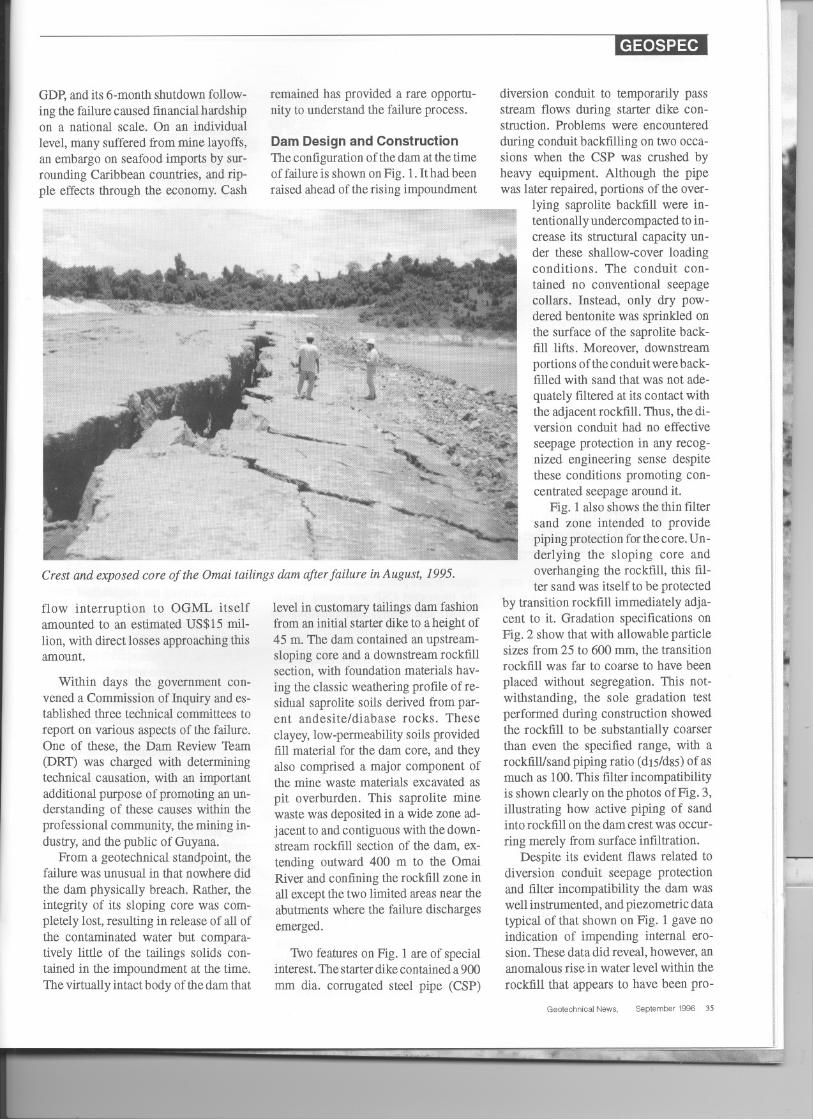
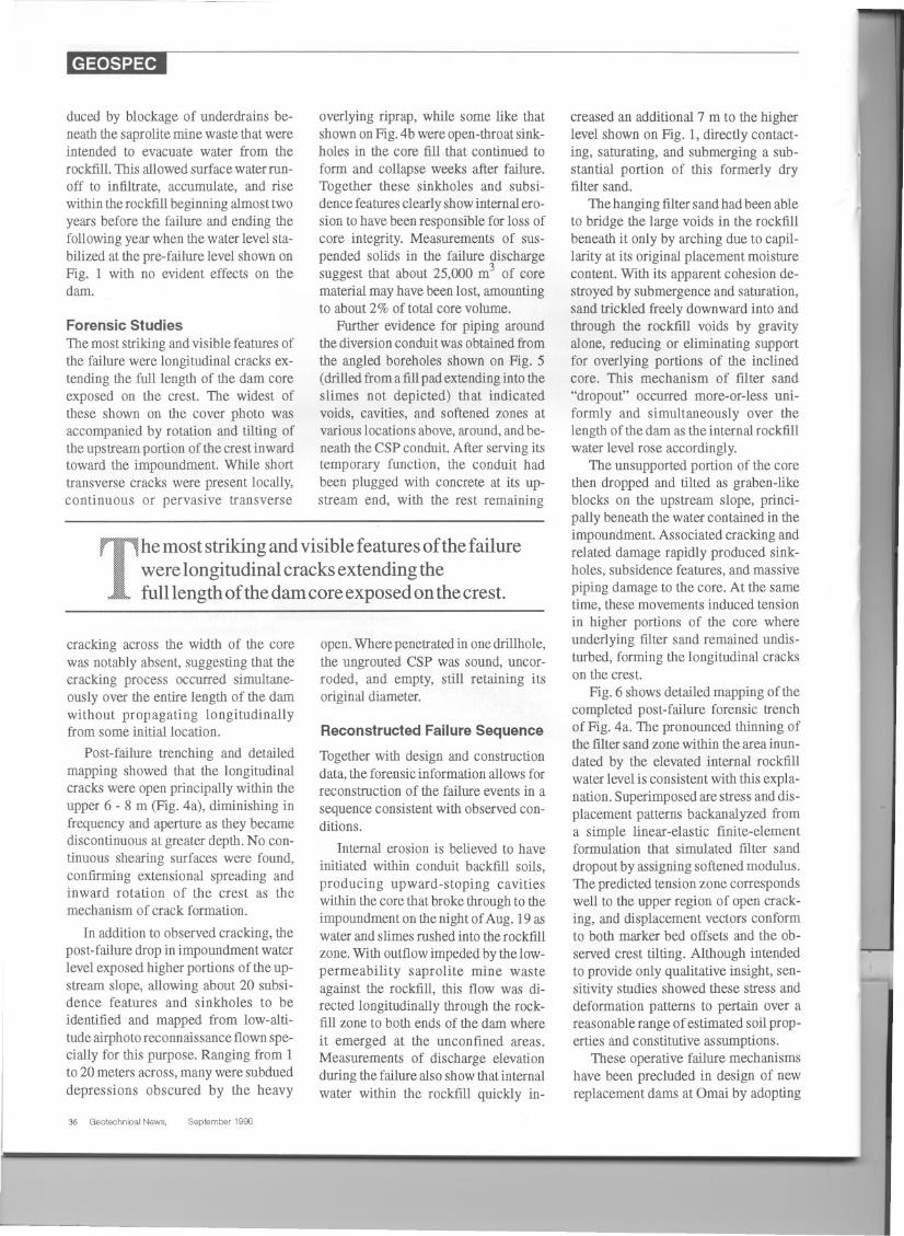
Dam Design and ConstructionThe configuration of the dam at the timeof failure is shown on Fig. 1. It had beenraised ahead of the rising impoundment
Crest and exposed core of the Omai tailings dam after failure in August, 1995.
flow interruption to OGML itselfamounted to an estimated US$15 mil-lion, with direct losses approaching thisamount.
Within days the government con-vened a Commission of Inquiry and es-tablished three technical committees to
report on various aspects of the failure.One of these, the Dam Review Tham(DRT) was charged with determiningtechnical causation, with an importantadditional purpose of promoting an un-derstanding of these causes within theprofessional community, the mining in-dustry, and the public of Guyana.
From a geotechnical standpoint, thefailure was unusual in that nowhere didthe dam physically breach. Rather, theintegrity of its sloping core was com-pletely lost, resulting in release of all ofthe contaminated water but compara-tively little of the tailings solids con-tained in the impoundment at the time.The virtually intact body of thedam that
level in customary tailings dam fashionfrom an initial starter dike to a height of45 m. The dam contained an upstream-sloping core and a downstream rockfillsection, with foundation materials hav-
ing the classic weathering profile of re-sidual saprolite soils derived from par-ent andesite/diabase rocks. Theseclayey, low-permeabilitysoils providedfill material for the dam core, and theyalso comprised a major component ofthe mine waste materials excavated aspit overburden. This saprolite minewaste was deposited in a wide zone ad-jacent to and contiguous with thedown-stream rockfill section of the dam, ex-tending outward 400 m to the OmaiRiver and confining the rockfill zone inall except the two limited areas near theabutments where the failure dischargesemerged.
Tho features on Fig. I are of specialinterest.Thestarterdike containeda 900
mm dia. corrugated steel pipe (CSP)
GEOSPEC
diversion conduit to temporarily passstream flows during starter dike con-struction. Problems were encounteredduring conduit backfilling on two occa-sions when the CSP was crushed byheavy equipment. Although the pipewas later repaired, portions of the over-
lying saprolite backfill were in-tentionallyundercompacted to in-crease its structural capacity un-der these shallow-cover loadingconditions. The conduit con-tained no conventional seepagecollars. Instead, only dry pow-dered bentonite was sprinkled onthe surface of the saprolite back-fill lifts. Moreover, downstreamportions of the conduitwere back-filled with sand that was not ade-quately filtered at its contact withthe adjacentrockfill. Thus, thedi-version conduit had no effectiveseepage protection in any recog-nized engineering sense despitethese conditions promoting con-centrated seepage around it.
Fig. 1 also shows the thin filtersand zone intended to providepiping protection for thecore. Un-derlying the sloping core andoverhanging the rockfill, this fil-ter sand was itself to be protected
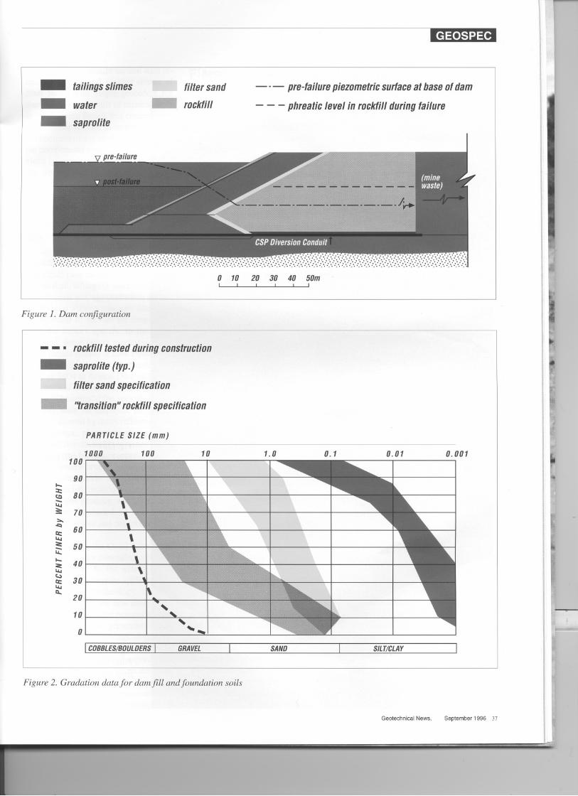
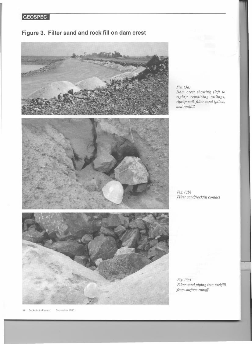
by transition rockfill immediately adja-cent to it. Gradation specifications onFig. 2 show that with allowable particlesizes from 25 to 600 mm, the transitionrockfill was far to coarse to have beenplaced without segregation. This not-withstanding, the sole gradation testperformed during construction showedthe rockfill to be substantially coarserthan even the specified range, with arockfill/sand piping ratio (dlS/d8S)of asmuch as 100.This filter incompatibilityis shown clearly on the photos of Fig. 3,illustrating how active piping of sandinto rockfill on the dam crest was occur-ring merely from surface infiltration.
Despite its evident flaws related todiversion conduit seepage protectionand filter incompatibility the dam waswell instrumented, and piezometric datatypical of that shown on Fig. 1gave noindication of impending internal ero-sion. These data did reveal, however, ananomalous rise in water level within therockfill that appears to have been pro-
I
GeotechnioalNews, September 1996 35
GEOSPEC
duced by blockage of underdrains be-neath the saprolite mine waste that wereintended to evacuate water from therockfill.This allowedsurface waterrun-off to infiltrate, accumulate, and risewithin the rockfill beginning almost twoyears before the failure and ending thefollowing year when the water level sta-bilized at the pre-failure level shown onFig. 1 with no evident effects on thedam.
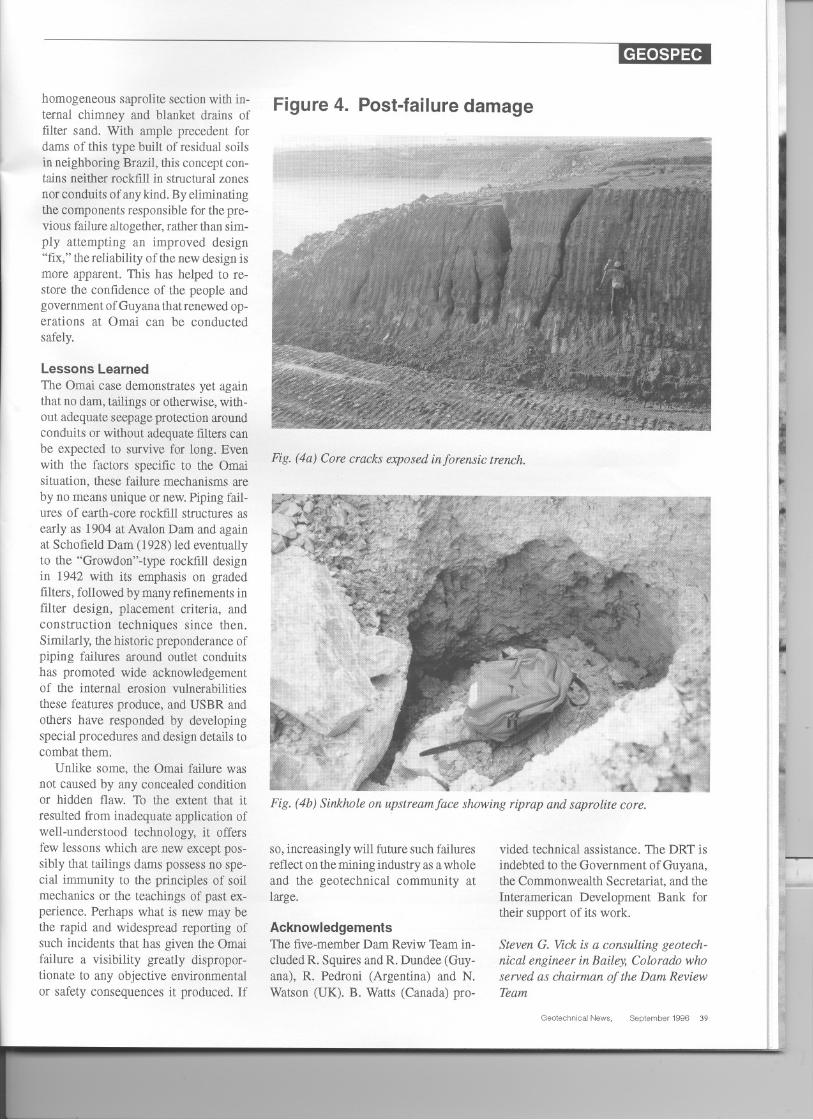
Forensic StudiesThe most striking and visible features ofthe failure were longitudinal cracks ex-tending the full length of the dam coreexposed on the crest. The widest ofthese shown on the cover photo wasaccompanied by rotation and tilting oftheupstream portion of the crest inwardtoward the impoundment. While shorttransverse cracks were present locally,continuous or pervasive transverse
overlying riprap, while some like thatshown onFig.4b were open-throatsink-holes in the core fill that continued toform and collapse weeks after failure.Together these sinkholes and subsi-dence featuresclearly showinternalero-sion to have been responsible for loss ofcore integrity. Measurements of sus-pended solids in the failure dischargesuggest that about 25,000 m3 of corematerial may have been lost, amountingto about 2% of total core volume.
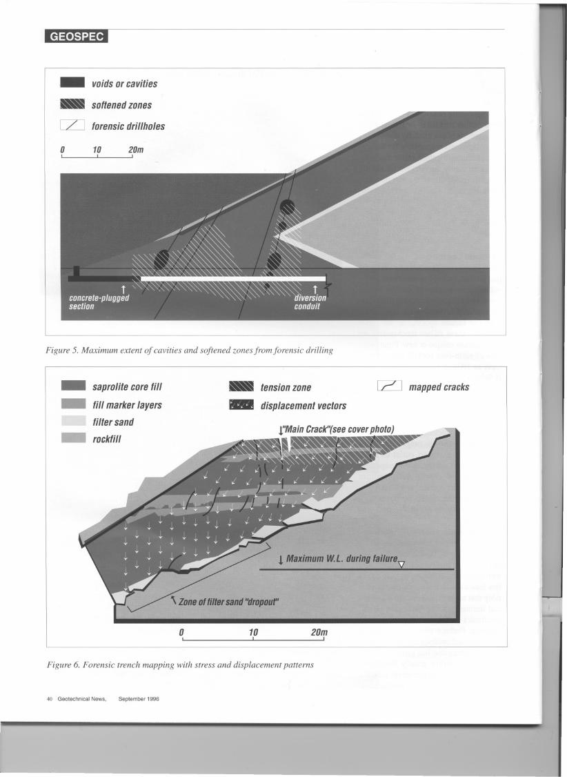
Further evidence for piping aroundthe diversionconduitwas obtainedfromthe angled boreholes shown on Fig. 5(drilled froma fillpad extendinginto theslimes not depicted) that indicatedvoids, cavities, and softened zones atvarious locationsabove, around,andbe-neath the CSP conduit.After serving itstemporary function, the conduit hadbeen plugged with concrete at its up-stream end, with the rest remaining
The most striking and visible features of the failurewere longitudinal cracks extending thefull length of the dam core exposed on the crest.
cracking across the width of the corewas notably absent, suggesting that thecracking process occurred simultane-ously over the entire length of the damwithout propagating longitudinallyfrom some initial location.
Post-failure trenching and detailedmapping showed that the longitudinalcracks were open principally within theupper 6 -8 m (Fig. 4a), diminishing infrequency and aperture as they becamediscontinuous at greater depth. No con-tinuous shearing surfaces were found,confirming extensional spreading andinward rotation of the crest as themechanism of crack formation.
In addition to observed cracking, thepost-failure drop in impoundment waterlevel exposed higher portions of theup-stream slope, allowing about 20 subsi-dence features and sinkholes to beidentified and mapped from low-alti-tude airphotoreconnaissance flownspe-cially for this purpose. Ranging from 1to 20 meters across, many weresubdueddepressions obscured by the heavy
36 Geotechnical News, September 1996
open.Wherepenetratedin one drillhole,the ungrouted CSP was sound, uncor-roded, and empty, still retaining itsoriginal diameter.
Reconstructed Failure Sequence
Together with design and constructiondata, the forensicinformation allows forreconstruction of the failure events in asequence consistent with observed con-ditions.
Internal erosion is believed to haveinitiated within conduit backfill soils,producing upward-stoping cavitieswithin the core that broke throughto theimpoundment on thenight ofAug. 19aswater and slimes rushed into the rockfillzone.With outflowimpededby the low-permeability saprolite mine wasteagainst the rockfill, this flow was di-rected longitudinally through the rock-fill zone to both ends of the dam whereit emerged at the unconfined areas.Measurements of discharge elevationduring the failure also showthat internalwater within the rockfill quickly in-
creased an additional 7 m to the higherlevel shown on Fig. 1, directly contact-ing, saturating, and submerging a sub-stantial portion of this formerly dryf1ltersand.
Thehanging f1ltersand had been ableto bridge the large voids in the rockfillbeneath it only by arching due to capil-larity at its original placement moisturecontent. With its apparent cohesion de-stroyed by submergence and saturation,sand trickled freely downward into andthrough the rockfill voids by gravityalone, reducing or eliminating supportfor overlying portions of the inclinedcore. This mechanism of f1lter sand"dropout" occurred more-or-less uni-formly and simultaneously over thelength of the dam as the internal rockfillwater level rose accordingly.
The unsupported portion of the corethen dropped and tilted as graben-likeblocks on the upstream slope, princi-pally beneath the water contained in theimpoundment. Associated cracking andrelated damage rapidly produced sink-holes, subsidence features, and massivepiping damage to the core. At the sametime, these movements induced tensionin higher portions of the core whereunderlying filter sand remained undis-turbed, forming the longitudinal crackson the crest.
Fig. 6 shows detailed mapping of thecompleted post-failure forensic trenchof Fig. 4a. The pronounced thinning ofthe f1ltersand zone within the area inun-dated by the elevated internal rockfillwater level is consistent with this expla-nation. Superimposed are stress and dis-placement patterns backanalyzed froma simple linear-elastic finite-elementformulation that simulated filter sanddropout by assigning softened modulus.The predicted tension zone correspondswell to the upper region of open crack-ing, and displacement vectors conformto both marker bed offsets and the ob-served crest tilting. Although intendedto provide only qualitative insight, sen-sitivity studies showed these stress anddeformation patterns to pertain over areasonable range of estimated soil prop-erties and constitutive assumptions.
These operative failure mechanismshave been precluded in design of newreplacement dams at Omai by adopting
r---
GEOSPEC
_ tailingsslimes_ water_ saprolite
filter sand_ rockfill
- -- pre-failure piezometric surface at base of dam
- - - phreatic level in rockfill during failure
o 10 20 30 40 50mI I I I I I
Figure 1. Dam configuration
- -. rockfill tested during construction_ saprolite (typ.)
filter sand specification_ "transition"rockfillspecification
PARTICLESIZE (mm)
1.0 0.1 0.01 0.001
o
C088LES/BOULDERSI GRAVEL
Figure 2. Gradation data for dam fill and foundation soils
GeotechnicalNews, September 1996 37
1000 100 10100
90....:r::
801:::1-LL.I
70::...
oQ60cr:
LL.I:e: 50-"'-....
40:e:LL.Ic.:o
30cr:LL.IQ.
20
10
0
GEOSPEC
Figure 3. Filter sand and rock fill on dam crest--
~,'"--
38 Geotechnical News. September 1996
,I
Fig. (3a)Dam crest showing (left toright): remaining tailings,riprap coil, filter sand (piles),and roclifill
Fig. (3b)Filter sandJroclifillcontact
Fig. (3c)Filter sand piping into roclifillfrom surface runoff
r--I
homogeneous saprolite section with in-ternal chimney and blanket drains offilter sand. With ample precedent fordams of this type built of residual soilsin neighboring Brazil, this conceptcon-tains neither rockfill in structural zonesnor conduits of anykind. By eliminatingthe components responsible for thepre-vious failurealtogether,rather than sim-ply attempting an improved design"fix," thereliability of the new design ismore apparent. This has helped to re-store the confidence of the people andgovernmentof Guyanathat renewed op-erations at Omai can be conductedsafely.
Lessons Learned
The Omai case demonstrates yet againthat no dam, tailings or otherwise,with-out adequate seepage protection aroundconduits or without adequate filters canbe expected to survive for long. Evenwith the factors specific to the Omaisituation, these failure mechanisms areby no means unique or new.Piping fail-ures of earth-core rockfill structures asearly as 1904 at AvalonDam and againat Schofield Dam (1928) led eventuallyto the "Growdon"-type rockfill designin 1942 with its emphasis on gradedfilters, followed by manyrefinementsinfilter design, placement criteria, andconstruction techniques since then.Similarly, the historic preponderance ofpiping failures around outlet conduitshas promoted wide acknowledgementof the internal erosion vulnerabilitiesthese features produce, and USBR andothers have responded by developingspecial procedures and design details tocombat them.
Unlike some, the Omai failure wasnot caused by any concealed conditionor hidden flaw. To the extent that itresulted from inadequate application ofwell-understood technology, it offersfew lessons which are new except pos-sibly that tailings dams possess no spe-cial immunity to the principles of soilmechanics or the teachings of past ex-perience. Perhaps what is new may bethe rapid and widespread reporting ofsuch incidents that has given the Omaifailure a visibility greatly dispropor-tionate to any objective environmentalor safety consequences it produced. If
GEOSPEC
Figure 4. Post-failure damage
Fig. (4a) Core cracks exposed inforensic trench.
- -----,;--
,..~t~."..
.
.~~
jc 'If.,ppo. r-
. . >-~c . ..' ..,. '- L- --.I.Fig. (4b) Sinkhole on upstream face showing riprap and saprolite core.
so, increasingly will future such failuresreflect on the mining industry as a wholeand the geotechnical community atlarge.
vided technical assistance. The DRT isindebted to the Government of Guyana,the Commonwealth Secretariat, and theInteramerican Development Bank fortheir support of its work.
AcknowledgementsThe five-memberDam Reviw Thamin-cluded R. Squires and R. Dundee (Guy-ana), R. Pedroni (Argentina) and N.Watson (UK). B. Watts (Canada) pro-
Steven G. Vick is a consulting geotech-nical engineer in Bailey, Colorado whoserved as chairman of the Dam ReviewTeam
GeoteohnioalNews, September 1996 39
GEOSPEC
Figure 5. Maximum extent of cavities and softened zones from forensic drilling-- saprolitecorefill
fill markerlayersfiltersand_ rockfill
~ tensionzone_ displacementvectors
[Z] mappedcracks
! Maximum~L. duringfailure2
j\ Zoneoffillersand"dropouf'
oI
101
20mI
Figure 6. Forensic trench mapping with stress and displacement patterns
40 GeotechnicalNews, September 1996
_voidsor cavitiesI ..
softened zones
[Z] forensicdrillholes
0 10 20mI I I