Embed Size (px)
Citation preview
School of Mechanical, Materials and Mechatronics Engineering
Omni-Directional Wheelchair
Honours Thesis
Benjamin Woods
10218282
Bachelor of Engineering (Mechatronics)
Faculty of Engineering, Computing and Mathematics
Supervisors:
Associate Professor Thomas Braunl
Mr. Chris Croft
Centre for Intelligent Information Processing
School of Electrical and Electronics Engineering
30 October, 2006

ii
Benjamin Woods
12 Anaconda Place
Sorrento, WA 6020
30th October 2006
Professor Mark Bush
The Dean
Faculty of Engineering, Computing and Mathematics
The University of Western Australia
35 Stirling Highway
Crawley, WA 6009
Dear Professor Bush,
It is with pleasure that I present this thesis, entitled “Omni-Directional Wheelchair”
in partial fulfilment of the requirements for the degree of Bachelor of Engineering.
I hereby certify that both this document and the proceedings described within are
my own work unless otherwise stated.
Yours sincerely,
Benjamin Woods
10218282
iii

iv
Abstract
Since the beginning of 2004, the University of Western Australia’s Centre for
Intelligent Information Processing Systems (CIIPS) has been developing an omni-
directional wheelchair. Omni-directional vehicles can turn and drive in any direction,
including directly sideways. Therefore, an omni-directional wheelchair allows the
user to navigate through a confined environment with less difficulty than would
otherwise be possible with a conventional wheelchair.
This project aims to improve the driving accuracy, human interface and comfort
of the already existing omni-directional wheelchair found in the mobile robotics
laboratory at the University of Western Australia. This will be accomplished by
altering the wheels, batteries, motor driver cards, joystick, control software, chassis
and suspension system.
v

vi
Acknowledgements
I would like to thank the following people for helping me produce this work. Without
them, it would surely not have been possible.
• Associate Professor Thomas Braunl for your guidance throughout the life of
this project (even whilst in Germany).
• Mr. Chris Croft for catching the handball from Thomas.
• Dr. Nathan Scott for your unforgiving eye and advice regarding the wheelchair
suspension system.
• The friendly staff and students within CIIPS and the EE workshops. It has
been a pleasure to work with you for a year.
• My family and friends for putting up with my scarce free time over the past
year and providing sound advice.
In addition to this, two organisations have been a great help in this project:
• DNM for supplying the university with the 4 shock absorbers necessary for the
project - at no cost! Along with shock absorbers for mountain bikes, DNM
also provide a large range of other suspension systems for bicycles and dirt
bikes. More details available at http://www.dnmsuspension.com/.
• TADWA for their supply of knowledge regarding practical wheelchair design.
TADWA provide a range of help for disabled people in WA. More details
available at http://www.technicalaidwa.org.au/.
vii

viii
Contents
1 Introduction 1
1.1 Background . . . . . . . . . . . . . . . . . . . . . . . . . . . . . . . . 1
1.2 Objectives . . . . . . . . . . . . . . . . . . . . . . . . . . . . . . . . . 2
1.3 Thesis Structure . . . . . . . . . . . . . . . . . . . . . . . . . . . . . . 2
2 Literature Survey 3
2.1 Mecanum Wheels and Alternatives . . . . . . . . . . . . . . . . . . . 3
2.2 Control Methods . . . . . . . . . . . . . . . . . . . . . . . . . . . . . 5
2.3 Human Interface . . . . . . . . . . . . . . . . . . . . . . . . . . . . . 6
3 Hardware 7
3.1 General Arrangement . . . . . . . . . . . . . . . . . . . . . . . . . . . 7
3.2 Mecanum Wheels . . . . . . . . . . . . . . . . . . . . . . . . . . . . . 9
3.2.1 Technical Details . . . . . . . . . . . . . . . . . . . . . . . . . 9
3.2.2 Kinematics . . . . . . . . . . . . . . . . . . . . . . . . . . . . 9
3.2.3 Wheel Rims . . . . . . . . . . . . . . . . . . . . . . . . . . . . 12
3.3 Motors . . . . . . . . . . . . . . . . . . . . . . . . . . . . . . . . . . . 13
3.4 EyeBot . . . . . . . . . . . . . . . . . . . . . . . . . . . . . . . . . . . 14
3.5 Batteries . . . . . . . . . . . . . . . . . . . . . . . . . . . . . . . . . . 15
3.6 Position Sensitive Devices . . . . . . . . . . . . . . . . . . . . . . . . 16
3.7 Footrests . . . . . . . . . . . . . . . . . . . . . . . . . . . . . . . . . . 16
4 Motor Driver Cards 17
4.1 Introduction . . . . . . . . . . . . . . . . . . . . . . . . . . . . . . . . 17
ix
CONTENTS
4.2 Selection . . . . . . . . . . . . . . . . . . . . . . . . . . . . . . . . . . 18
4.3 Installation . . . . . . . . . . . . . . . . . . . . . . . . . . . . . . . . 19
4.4 Programming . . . . . . . . . . . . . . . . . . . . . . . . . . . . . . . 20
5 Joystick 23
5.1 Introduction . . . . . . . . . . . . . . . . . . . . . . . . . . . . . . . . 23
5.2 Selection . . . . . . . . . . . . . . . . . . . . . . . . . . . . . . . . . . 23
5.3 Installation . . . . . . . . . . . . . . . . . . . . . . . . . . . . . . . . 26
5.4 Programming . . . . . . . . . . . . . . . . . . . . . . . . . . . . . . . 28
6 Low Level Driving Routines 31
6.1 Introduction . . . . . . . . . . . . . . . . . . . . . . . . . . . . . . . . 31
6.2 Design . . . . . . . . . . . . . . . . . . . . . . . . . . . . . . . . . . . 32
7 Suspension System 35
7.1 Introduction . . . . . . . . . . . . . . . . . . . . . . . . . . . . . . . . 35
7.2 Design . . . . . . . . . . . . . . . . . . . . . . . . . . . . . . . . . . . 36
8 Results, Testing and Simulation 43
8.1 Motor Control . . . . . . . . . . . . . . . . . . . . . . . . . . . . . . . 43
8.2 Joystick . . . . . . . . . . . . . . . . . . . . . . . . . . . . . . . . . . 43
8.3 Suspension and Chassis . . . . . . . . . . . . . . . . . . . . . . . . . . 46
8.4 Modelling and Simulation . . . . . . . . . . . . . . . . . . . . . . . . 47
9 Conclusion 49
9.1 Outcomes . . . . . . . . . . . . . . . . . . . . . . . . . . . . . . . . . 49
9.2 Recommendations . . . . . . . . . . . . . . . . . . . . . . . . . . . . . 49
Bibliography 51
A Code 55
A.1 ODW.h . . . . . . . . . . . . . . . . . . . . . . . . . . . . . . . . . . 55
A.2 ODW.c . . . . . . . . . . . . . . . . . . . . . . . . . . . . . . . . . . . 57
A.3 ODW MotorCtrl.h . . . . . . . . . . . . . . . . . . . . . . . . . . . . 60
x
A.4 ODW MotorCtrl.c . . . . . . . . . . . . . . . . . . . . . . . . . . . . 65
A.5 ODW Joystick.h . . . . . . . . . . . . . . . . . . . . . . . . . . . . . 71
A.6 ODW Joystick.c . . . . . . . . . . . . . . . . . . . . . . . . . . . . . . 75
A.7 ODW IR.h . . . . . . . . . . . . . . . . . . . . . . . . . . . . . . . . . 80
A.8 ODW IR.c . . . . . . . . . . . . . . . . . . . . . . . . . . . . . . . . . 82
A.9 Makefile . . . . . . . . . . . . . . . . . . . . . . . . . . . . . . . . . . 87
A.10 Makeincl . . . . . . . . . . . . . . . . . . . . . . . . . . . . . . . . . . 88
A.11 test.c . . . . . . . . . . . . . . . . . . . . . . . . . . . . . . . . . . . . 89
A.12 mctest.c . . . . . . . . . . . . . . . . . . . . . . . . . . . . . . . . . . 90
A.13 joytest.c . . . . . . . . . . . . . . . . . . . . . . . . . . . . . . . . . . 92
A.14 joytest2.c . . . . . . . . . . . . . . . . . . . . . . . . . . . . . . . . . 97
A.15 psdtest.c . . . . . . . . . . . . . . . . . . . . . . . . . . . . . . . . . . 103
B Mechanical and Electrical Designs 105
B.1 Joystick Circuit . . . . . . . . . . . . . . . . . . . . . . . . . . . . . . 105
B.2 Suspension Designs . . . . . . . . . . . . . . . . . . . . . . . . . . . . 107
C Information and Brochures 121
C.1 Roboteq AX1500 . . . . . . . . . . . . . . . . . . . . . . . . . . . . . 122
xi

xii
List of Figures
2.1 NASA OmniBot mobile base (Lippitt & Jones 1998) . . . . . . . . . . 3
2.2 Airtrax Sidewinder lift truck (Airtrax 2006) . . . . . . . . . . . . . . 4
2.3 New Mecanum wheel design (McCandless 2001) . . . . . . . . . . . . 4
3.1 The Mecanum wheel design . . . . . . . . . . . . . . . . . . . . . . . 9
3.2 Force components in the Mecanum wheel (seen from below) . . . . . 10
3.3 Wheel rotations for different driving directions (seen from below) . . 10
3.4 The Mecanum wheel rims after machining . . . . . . . . . . . . . . . 13
3.5 A 24V brushed DC motor . . . . . . . . . . . . . . . . . . . . . . . . 13
3.6 EyeBot controller MK4 (front and back views) . . . . . . . . . . . . . 14
3.7 Original car batteries and new sealed, deep-cycle gel batteries . . . . 15
3.8 Position sensitive devices (PSDs) . . . . . . . . . . . . . . . . . . . . 16
3.9 Wheelchair footrests donated by TADWA . . . . . . . . . . . . . . . 16
4.1 Pulse-width modulation (PWM) signal . . . . . . . . . . . . . . . . . 18
4.2 The new Roboteq AX1500 motor controller cards . . . . . . . . . . . 19
4.3 Roboteq input/output power connections . . . . . . . . . . . . . . . . 20
4.4 Daisy-chain serial cable for Roboteq AX1500 cards . . . . . . . . . . 20
5.1 A 2 axis joystick compared to a 3 axis joystick . . . . . . . . . . . . . 24
5.2 The 3 joysticks purchased and tested . . . . . . . . . . . . . . . . . . 25
5.3 The USB connection originally on the joystick . . . . . . . . . . . . . 27
5.4 The new joystick circuit . . . . . . . . . . . . . . . . . . . . . . . . . 27
6.1 Flow chart for the main ODW code . . . . . . . . . . . . . . . . . . . 33
xiii
LIST OF FIGURES
6.2 Flow charts for the IR and Joystick modules . . . . . . . . . . . . . . 34
6.3 Flow chart for the MotorCtrl module . . . . . . . . . . . . . . . . . . 34
7.1 DNM DV-22 bicycle shock absorbers . . . . . . . . . . . . . . . . . . 36
7.2 Battery box design . . . . . . . . . . . . . . . . . . . . . . . . . . . . 37
7.3 Battery box lid and chair mount . . . . . . . . . . . . . . . . . . . . . 38
7.4 Perpendicular requirement for the adopted Mecanum wheel design . . 39
7.5 A basic but inadequate suspension design . . . . . . . . . . . . . . . . 39
7.6 Two alternative trailing arm designs . . . . . . . . . . . . . . . . . . 39
7.7 Trailing arm connection to the chassis . . . . . . . . . . . . . . . . . . 40
7.8 The forces experienced by the trailing arm suspension . . . . . . . . . 40
7.9 A steel gusset is used to add strength . . . . . . . . . . . . . . . . . . 41
7.10 The shock absorber angle determines the effective spring constant . . 42
8.1 Actual motor speeds achieved . . . . . . . . . . . . . . . . . . . . . . 44
8.2 A textual joystick testing program . . . . . . . . . . . . . . . . . . . . 45
8.3 A graphical joystick testing program . . . . . . . . . . . . . . . . . . 45
8.4 The wheelchair model in EyeSim . . . . . . . . . . . . . . . . . . . . 48
9.1 The wheelchair after all alterations and improvements . . . . . . . . . 50
B.1 The joystick circuit schematic . . . . . . . . . . . . . . . . . . . . . . 105
B.2 The joystick PCB design . . . . . . . . . . . . . . . . . . . . . . . . . 106
xiv
List of Tables
3.1 Omni-directional wheelchair components summary - February 2006 . 8
4.1 RS232 settings for Roboteq AX1500 cards . . . . . . . . . . . . . . . 20
4.2 Character strings for communication with daisy-chained Roboteq cards 21
4.3 Communication language for Roboteq AX1500 cards . . . . . . . . . 22
5.1 The 3 joysticks purchased and tested . . . . . . . . . . . . . . . . . . 25
5.2 EyeBot I/O pins used . . . . . . . . . . . . . . . . . . . . . . . . . . . 28
5.3 RoBIOS commands for reading buttons . . . . . . . . . . . . . . . . . 29
5.4 RoBIOS commands for reading potentiometers . . . . . . . . . . . . . 29
8.1 Actual motor speeds achieved . . . . . . . . . . . . . . . . . . . . . . 44
xv

xvi
Nomenclature
Acronyms
ASCII American Standard Code for Information Interchange
DOF Degrees Of Freedom
EEPROM Electrically Erasable Programmable Read-Only Memory
FSJ Force Sensing Joystick
I/O Input/Output
IR Infra-Red
MOSFET Metal-Oxide-Semiconductor Field-Effect Transistor
MotorCtrl Motor control
ODV/ODW Omni-Directional Vehicle/Wheelchair
PSD Position Sensitive Device
PSJ Position Sensing Joystick
PWM Pulse-Width Modulation
RS232 RETMA Standard 232
SHS Square Hollow Section
USB Universal Serial Bus
WC WheelChair
xvii

LIST OF TABLES
Mathematical Notation
r The radius of the Mecanum wheels
d The width of the wheelchair (from wheel to wheel)
s The length of the wheelchair (from wheel to wheel)
VX The forwards/backwards component of the wheelchair velocity (positive forwards)
VY The left/right component of the wheelchair velocity (positive left)
ϕ The rotation speed of the wheelchair (positive counter clockwise)
θi The rotational speed of wheel i (positive forwards)
x The left/right axis of the joystick (positive right)
y The forwards/backwards axis of the joystick (positive forwards)
z The rotational axis of the joystick (positive clockwise)
t The throttle of the joystick (positive up)
xviii
Chapter 1
Introduction
1.1 Background
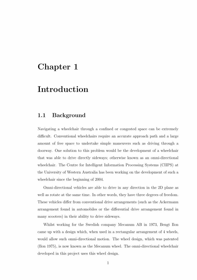
Navigating a wheelchair through a confined or congested space can be extremely
difficult. Conventional wheelchairs require an accurate approach path and a large
amount of free space to undertake simple maneuvers such as driving through a
doorway. One solution to this problem would be the development of a wheelchair
that was able to drive directly sideways; otherwise known as an omni-directional
wheelchair. The Centre for Intelligent Information Processing Systems (CIIPS) at
the University of Western Australia has been working on the development of such a
wheelchair since the beginning of 2004.
Omni-directional vehicles are able to drive in any direction in the 2D plane as
well as rotate at the same time. In other words, they have three degrees of freedom.
These vehicles differ from conventional drive arrangements (such as the Ackermann
arrangement found in automobiles or the differential drive arrangement found in
many scooters) in their ability to drive sideways.
Whilst working for the Swedish company Mecanum AB in 1973, Bengt Ilon
came up with a design which, when used in a rectangular arrangement of 4 wheels,
would allow such omni-directional motion. The wheel design, which was patented
(Ilon 1975), is now known as the Mecanum wheel. The omni-directional wheelchair
developed in this project uses this wheel design.
1
1.2. OBJECTIVES
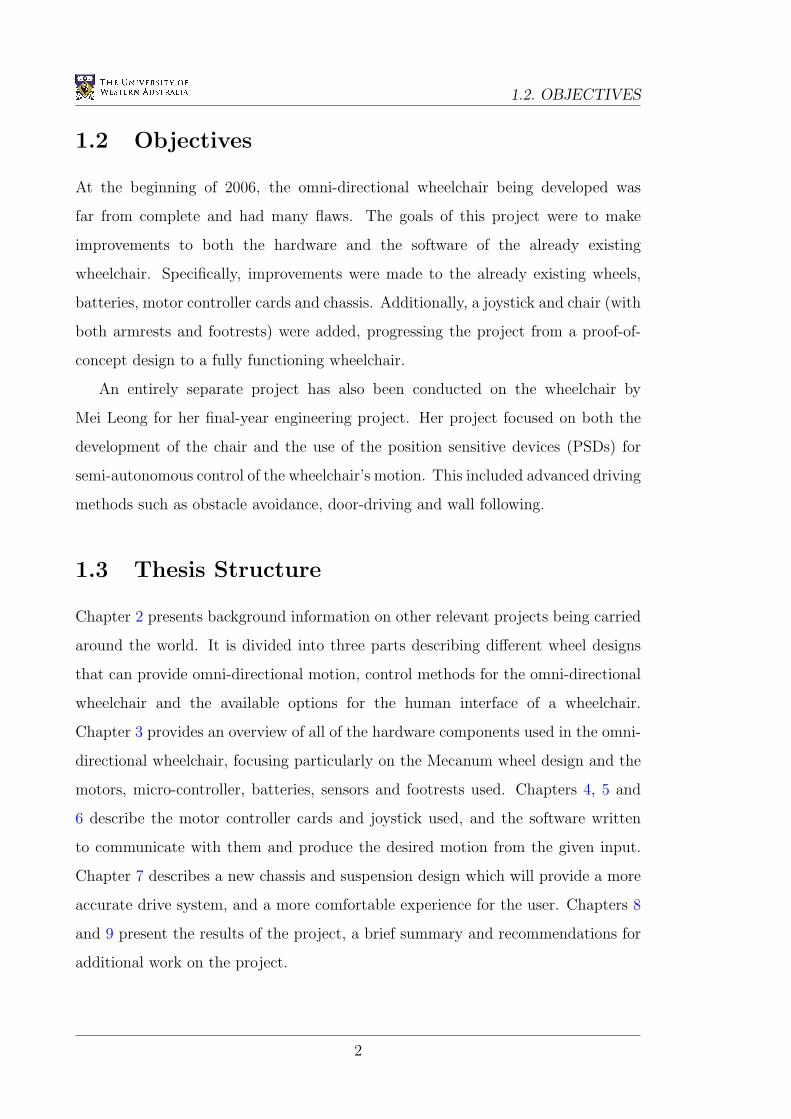
1.2 Objectives
At the beginning of 2006, the omni-directional wheelchair being developed was
far from complete and had many flaws. The goals of this project were to make
improvements to both the hardware and the software of the already existing
wheelchair. Specifically, improvements were made to the already existing wheels,
batteries, motor controller cards and chassis. Additionally, a joystick and chair (with
both armrests and footrests) were added, progressing the project from a proof-of-
concept design to a fully functioning wheelchair.
An entirely separate project has also been conducted on the wheelchair by
Mei Leong for her final-year engineering project. Her project focused on both the
development of the chair and the use of the position sensitive devices (PSDs) for
semi-autonomous control of the wheelchair’s motion. This included advanced driving
methods such as obstacle avoidance, door-driving and wall following.
1.3 Thesis Structure
Chapter 2 presents background information on other relevant projects being carried
around the world. It is divided into three parts describing different wheel designs
that can provide omni-directional motion, control methods for the omni-directional
wheelchair and the available options for the human interface of a wheelchair.
Chapter 3 provides an overview of all of the hardware components used in the omni-
directional wheelchair, focusing particularly on the Mecanum wheel design and the
motors, micro-controller, batteries, sensors and footrests used. Chapters 4, 5 and
6 describe the motor controller cards and joystick used, and the software written
to communicate with them and produce the desired motion from the given input.
Chapter 7 describes a new chassis and suspension design which will provide a more
accurate drive system, and a more comfortable experience for the user. Chapters 8
and 9 present the results of the project, a brief summary and recommendations for
additional work on the project.
2
Chapter 2
Literature Survey
2.1 Mecanum Wheels and Alternatives
Omni-directional vehicles (ODVs) are by no means a new concept. Ilon (1975)
details the design of the Mecanum wheel, which allows the omni-directional
movement of a vehicle. This wheel is commonly used in robotic applications
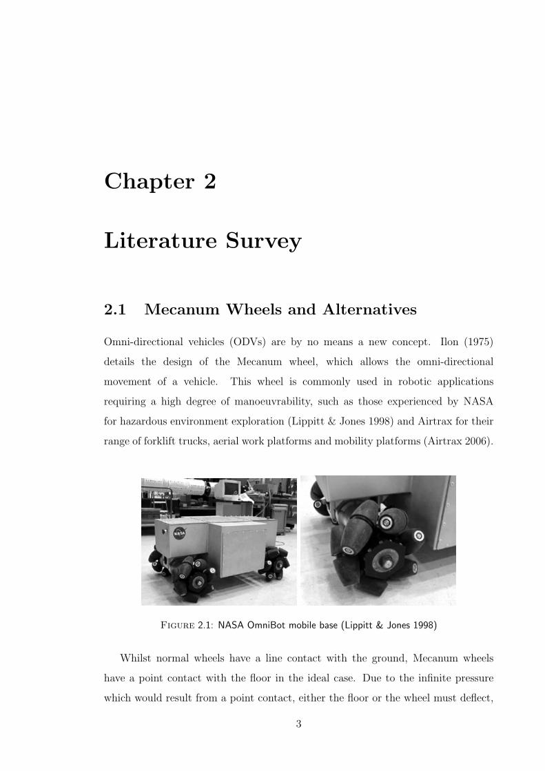
requiring a high degree of manoeuvrability, such as those experienced by NASA
for hazardous environment exploration (Lippitt & Jones 1998) and Airtrax for their
range of forklift trucks, aerial work platforms and mobility platforms (Airtrax 2006).
Figure 2.1: NASA OmniBot mobile base (Lippitt & Jones 1998)
Whilst normal wheels have a line contact with the ground, Mecanum wheels
have a point contact with the floor in the ideal case. Due to the infinite pressure
which would result from a point contact, either the floor or the wheel must deflect,
3

2.1. MECANUM WHEELS AND ALTERNATIVES
Figure 2.2: Airtrax Sidewinder lift truck (Airtrax 2006)
resulting in an area of contact. Regardless, the higher contact pressures that occur
with Mecanum wheels can be minimised by using fewer rollers, with 6 rollers being
found to be optimal (Dickerson & Lapin 1991). This fact was used by McCandless
(2001) when developing his new Mecanum wheel design at the University of Western
Australia.
Figure 2.3: New Mecanum wheel design (McCandless 2001)
One disadvantage of the Mecanum design is the inefficient use of the kinetic
energy supplied to the wheels by the motors. Due to the rotation of the exterior
rollers, only a component of the force at the perimeter of the wheel is applied to the
ground and the resulting force only partially contributes to the motion of the vehicle.
Diegel, Badve, Bright, Potgieter & Tlale (2002) address this problem by introducing
two new wheel designs, one with lockable rollers and the other with rotatable rollers.
Although these designs are more efficient, their increased complexity makes them
almost impractical in a university project with a limited budget.
4
CHAPTER 2. LITERATURE SURVEY
Other designs use balls to facilitate the omni-directional movement, such as those
used by West & Asada (1992) with the balls arranged along a crawler, and by Wada
& Asada (1998) and Tahboub & Asada (2000) where four balls are used as the
points of contact with the ground. These designs are relatively complicated and
provide very few additional advantages over the Mecanum wheel design. As a result
they are less likely to be adopted in a commercial wheelchair application, where
manufacturing and maintenance costs are greatly reduced by simplicity.
2.2 Control Methods
The forward and inverse kinematics of the rectangular Mecanum wheel arrangement
used in this project are derived by Viboonchaicheep, Shimada & Kosaka (2003).
Unfortunately, using the wheel rotations and forward kinematic equations to
determine the vehicle’s current motion (also known as position rectification) is not
possible with the Mecanum wheels being used in this project. This is due to the high
level of slip experienced during normal operation providing inaccurate predictions
of the ODV’s velocity. As an alternative, a visual dead-reckoning system using
a camera and optical flow analysis can be used to determine the change in the
ODV’s position (Nagatani, Tachibana, Sofne & Tanaka 2000), (Shimada, Yajima,
Viboonchaicheep & Samura 2005) and (Cooney, Xu & Bright 2004). If accurate
feedback of the wheelchair’s position and/or velocity is required in a future project,
this technique would be the most appropriate.
It is not uncommon for the user of an electric wheelchair to experience strong
vibrations whilst driving. These vibrations have sometimes been known to excite the
user’s internal organs at their natural frequency, causing discomfort and sometimes
nausea. By avoiding the natural frequency of the chair and human organs using
frequency shape control, this effect can be minimised (Terashima, Miyoshi, Urbana
& Kitagawa 2004) and (Urbano, Terashima, Miyoshi & Kitagawa 2005). Although
this lies outside the scope of this project, if this problem is experienced at a future
date it can be rectified using the methods described in these two papers.
5
2.3. HUMAN INTERFACE
2.3 Human Interface
An alternative to the common position sensing joystick (PSJ) found in most
wheelchairs is the force sensing joystick (FSJ) or isometric joystick. This joystick
remains stationary, but measures the degree of force placed on it in both the x and y
axes. This requires virtually no range of hand motion, and allows easy optimisation
for each individual user. For example, these joysticks can be used to reduce the
effects of hand tremors on the vehicle’s motion (Ding, Cooper & Spaeth 2004).
Tests show that the PSJ and the FSJ provide similar accuracy and ease of use (Jones,
Cooper, Albright & DiGiovine 1998) and (Cooper, Jones, Fitzgerald, Boninger &
Albright 2000). The joystick used in this project has a third axis which is used to
control the third degree of freedom of the wheelchair. As a result, the wheelchair
continues to use the more conventional and intuitive PSJ.
For those individuals who do not have the ability to move their hands accurately,
there are the options of chin operated FSJs (Guo, Cooper, Boninger, Kwarciak
& Ammer 2002), or ultra-sonic non-contact head and voice activated control
(Coyle 1995). Finally, a touch screen displaying video footage of the current
surroundings can be used to control the vehicle (Kamiuchi & Maeyama 2004). Due
to the additional complexity of controlling an ODV, this project assumes a user who
has wrist movement which is acceptable for controlling a joystick.
As a user friendly alternative to obstacle avoidance, a variable impedance joystick
that increases the impedance of tilting the joystick in the direction of an obstacle can
be used (Kitagawa, Kobayashi, Beppu & Terashima 2001) and (Urbano, Terashima,
Miyoshi & Kitagawa 2004). This ensures the wheelchair’s motion always obeys
the users instructions even when obstacles are present, rather than altering the
trajectory of the vehicle. As an alternative to this method, the wheelchair requires
the user to manually enable the obstacle avoidance system. This ensures any altered
wheelchair trajectories are at least expected by the user, eliminating the need for
this complex arrangement.
6
Chapter 3
Hardware
3.1 General Arrangement
At the beginning of 2006, the omni-directional wheelchair project at the University
of Western Australia was a work in progress. The project was started by Iwasaki
(2005), who used the Mecanum wheels and low-level driving routines developed by
Voo (2000) to construct the basic frame and control software for this wheelchair. In
addition to this work, a suspension system and alternative Mecanum wheel design
had been developed for the miniature omni-directional driving robots used in the
CIIPS department (McCandless 2001).
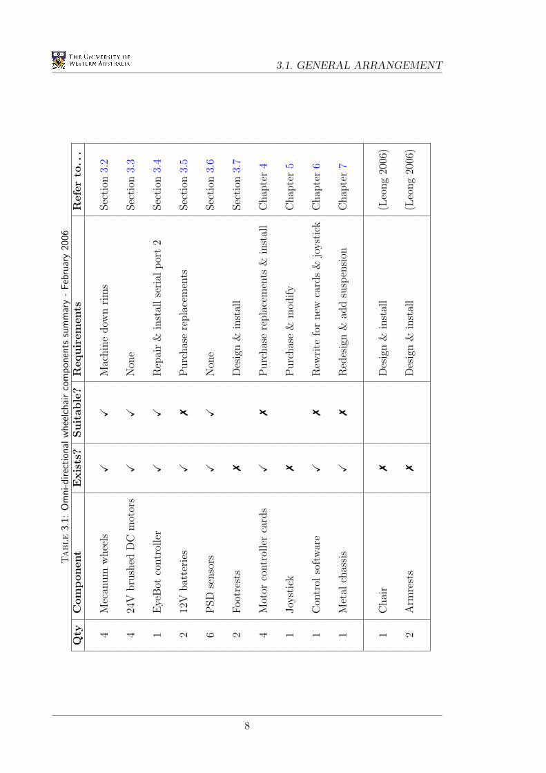
This project is an extension of these works, with the major aim of improving
the ease of use and accuracy of the wheelchair by altering its hardware. Table 3.1
shows the state of the wheelchair components at the beginning of 2006. In summary,
this project made improvements to the Mecanum wheels, batteries, footrests, motor
controller cards, human interface, control software and chassis, whilst improvements
were also made to the chair, armrests and high-level driver assistance system by
Leong (2006).
7
3.1. GENERAL ARRANGEMENTTable
3.1:
Om
ni-direc
tion
alw
hee
lchai
rco
mpon
ents
sum
mar
y-
Feb
ruar
y20
06Q
tyC
om
ponent
Exis
ts?
Suit
able
?R
equir
em
ents
Refe
rto
...
4M
ecan
um
whee
lsX
XM
achin
edow
nri
ms
Sec
tion
3.2
424
Vbru
shed
DC
mot
ors
XX
Non
eSec
tion
3.3
1E
yeB
otco
ntr
olle
rX
XR
epai
r&
inst
allse
rial
por
t2
Sec
tion
3.4
212
Vbat
teri
esX
7P
urc
has
ere
pla
cem
ents
Sec
tion
3.5
6P
SD
senso
rsX
XN
one
Sec
tion
3.6
2Foot
rest
s7
Des
ign
&in
stal
lSec
tion
3.7
4M
otor
contr
olle
rca
rds
X7
Purc
has
ere
pla
cem
ents
&in
stal
lC
hap
ter
4
1Joy
stic
k7
Purc
has
e&
modify
Chap
ter
5
1C
ontr
olso
ftw
are
X7
Rew
rite
for
new
card
s&
joyst
ick
Chap
ter
6
1M
etal
chas
sis
X7
Red
esig
n&
add
susp
ensi
onC
hap
ter
7
1C
hai
r7
Des
ign
&in
stal
l(L
eong
2006
)
2A
rmre
sts
7D
esig
n&
inst
all
(Leo
ng
2006
)
8
CHAPTER 3. HARDWARE
3.2 Mecanum Wheels
3.2.1 Technical Details
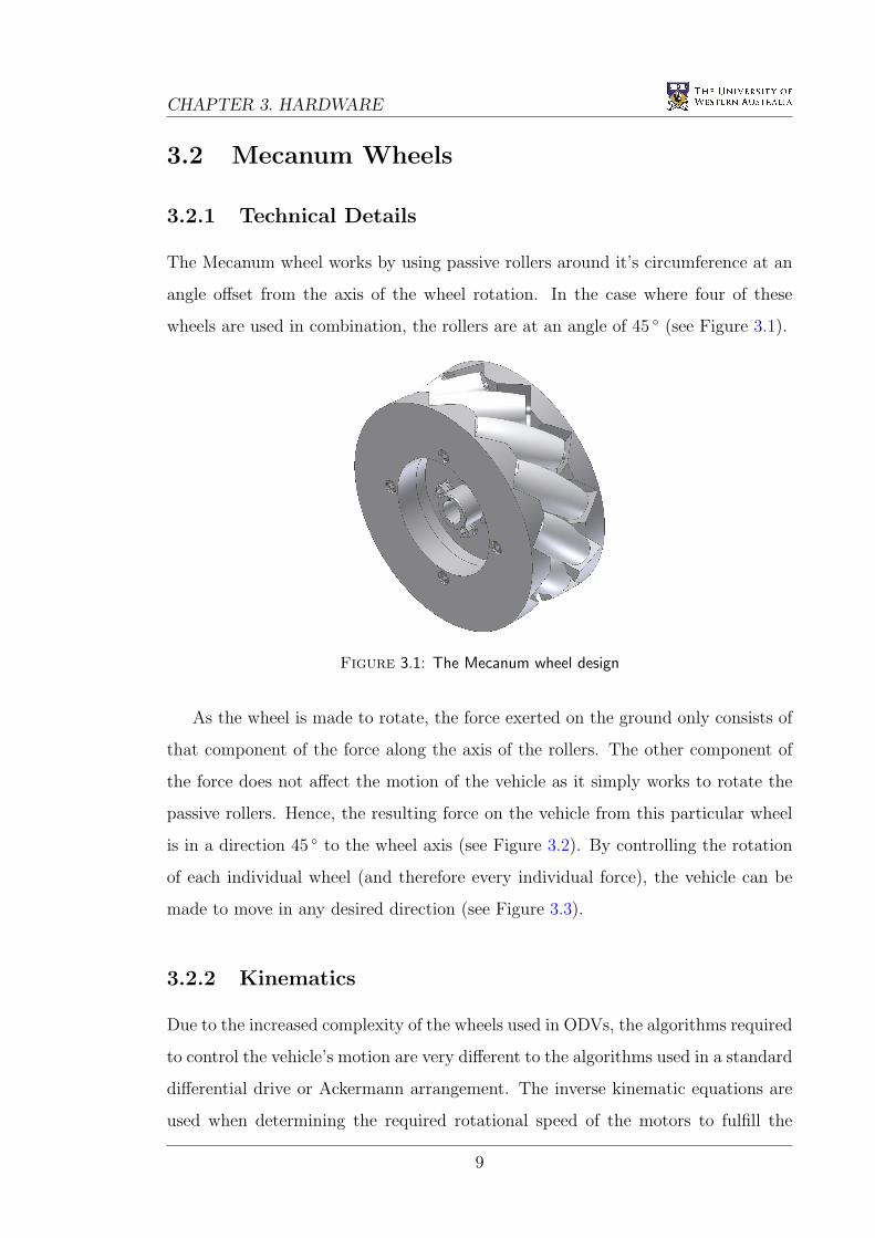
The Mecanum wheel works by using passive rollers around it’s circumference at an
angle offset from the axis of the wheel rotation. In the case where four of these
wheels are used in combination, the rollers are at an angle of 45 (see Figure 3.1).
Figure 3.1: The Mecanum wheel design
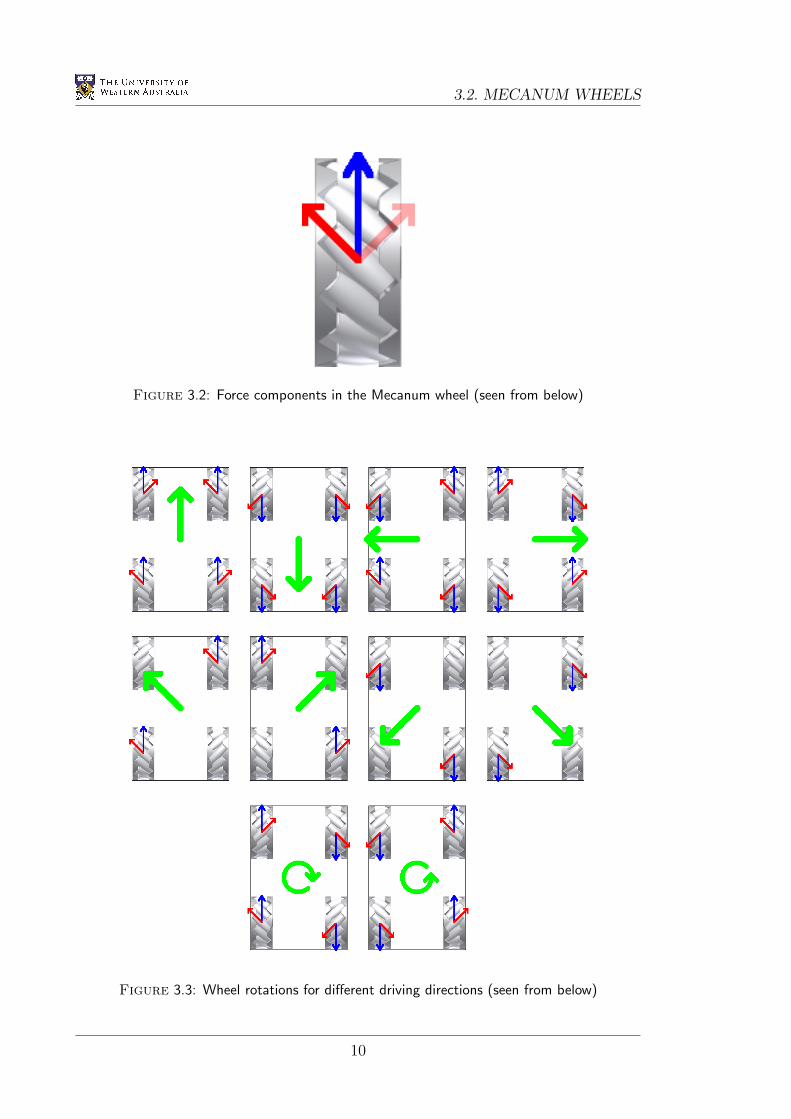
As the wheel is made to rotate, the force exerted on the ground only consists of
that component of the force along the axis of the rollers. The other component of
the force does not affect the motion of the vehicle as it simply works to rotate the
passive rollers. Hence, the resulting force on the vehicle from this particular wheel
is in a direction 45 to the wheel axis (see Figure 3.2). By controlling the rotation
of each individual wheel (and therefore every individual force), the vehicle can be
made to move in any desired direction (see Figure 3.3).
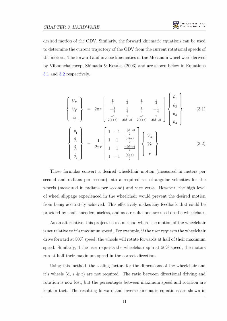
3.2.2 Kinematics
Due to the increased complexity of the wheels used in ODVs, the algorithms required
to control the vehicle’s motion are very different to the algorithms used in a standard
differential drive or Ackermann arrangement. The inverse kinematic equations are
used when determining the required rotational speed of the motors to fulfill the
9
3.2. MECANUM WHEELS
Figure 3.2: Force components in the Mecanum wheel (seen from below)
Figure 3.3: Wheel rotations for different driving directions (seen from below)
10
CHAPTER 3. HARDWARE
desired motion of the ODV. Similarly, the forward kinematic equations can be used
to determine the current trajectory of the ODV from the current rotational speeds of
the motors. The forward and inverse kinematics of the Mecanum wheel were derived
by Viboonchaicheep, Shimada & Kosaka (2003) and are shown below in Equations
3.1 and 3.2 respectively.
VX
VY
ϕ
= 2πr
14
14
14
14
−14
14
14
−14
−12(d+s)
12(d+s)
−12(d+s)
12(d+s)
θ1
θ2
θ3
θ4
(3.1)
θ1
θ2
θ3
θ4
=
1
2πr
1 −1 −(d+s)
2
1 1 (d+s)2
1 1 −(d+s)2
1 −1 (d+s)2
VX
VY
ϕ
(3.2)
These formulas convert a desired wheelchair motion (measured in meters per
second and radians per second) into a required set of angular velocities for the
wheels (measured in radians per second) and vice versa. However, the high level
of wheel slippage experienced in the wheelchair would prevent the desired motion
from being accurately achieved. This effectively makes any feedback that could be
provided by shaft encoders useless, and as a result none are used on the wheelchair.
As an alternative, this project uses a method where the motion of the wheelchair
is set relative to it’s maximum speed. For example, if the user requests the wheelchair
drive forward at 50% speed, the wheels will rotate forwards at half of their maximum
speed. Similarly, if the user requests the wheelchair spin at 50% speed, the motors
run at half their maximum speed in the correct directions.
Using this method, the scaling factors for the dimensions of the wheelchair and
it’s wheels (d, s & r) are not required. The ratio between directional driving and
rotation is now lost, but the percentages between maximum speed and rotation are
kept in tact. The resulting forward and inverse kinematic equations are shown in
11
3.2. MECANUM WHEELS
Equations 3.3 and 3.4 respectively. This implementation also requires the wheel
speeds are occasionally scaled down to ensure the maximum wheel speed is kept at
100% in all situations (see Appendix A.4).
VX
VY
ϕ
=1
4
1 1 1 1
−1 1 1 −1
−1 1 −1 1
θ1
θ2
θ3
θ4
(3.3)
θ1
θ2
θ3
θ4
=
1 −1 −1
1 1 1
1 1 −1
1 −1 1
VX
VY
ϕ
(3.4)
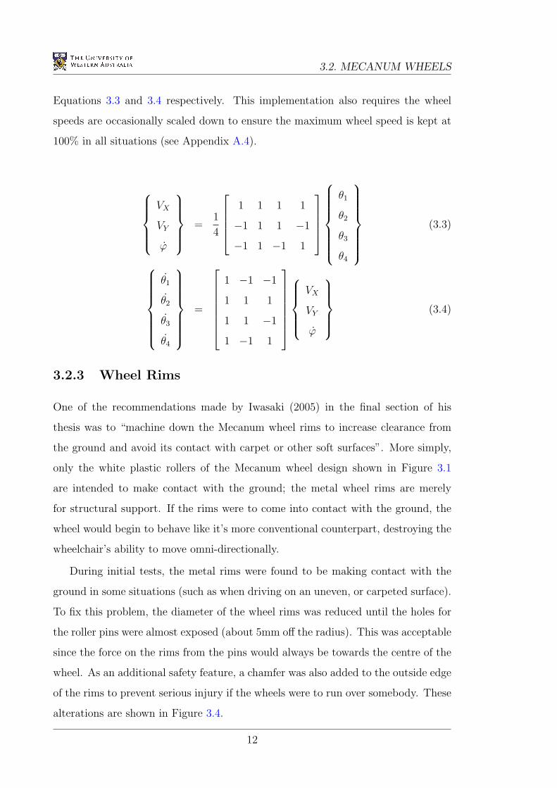
3.2.3 Wheel Rims
One of the recommendations made by Iwasaki (2005) in the final section of his
thesis was to “machine down the Mecanum wheel rims to increase clearance from
the ground and avoid its contact with carpet or other soft surfaces”. More simply,
only the white plastic rollers of the Mecanum wheel design shown in Figure 3.1
are intended to make contact with the ground; the metal wheel rims are merely
for structural support. If the rims were to come into contact with the ground, the
wheel would begin to behave like it’s more conventional counterpart, destroying the
wheelchair’s ability to move omni-directionally.
During initial tests, the metal rims were found to be making contact with the
ground in some situations (such as when driving on an uneven, or carpeted surface).
To fix this problem, the diameter of the wheel rims was reduced until the holes for
the roller pins were almost exposed (about 5mm off the radius). This was acceptable
since the force on the rims from the pins would always be towards the centre of the
wheel. As an additional safety feature, a chamfer was also added to the outside edge
of the rims to prevent serious injury if the wheels were to run over somebody. These
alterations are shown in Figure 3.4.
12
CHAPTER 3. HARDWARE
Figure 3.4: The Mecanum wheel rims after machining
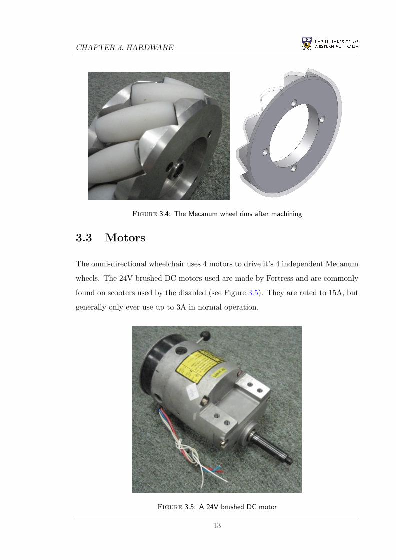
3.3 Motors
The omni-directional wheelchair uses 4 motors to drive it’s 4 independent Mecanum
wheels. The 24V brushed DC motors used are made by Fortress and are commonly
found on scooters used by the disabled (see Figure 3.5). They are rated to 15A, but
generally only ever use up to 3A in normal operation.
Figure 3.5: A 24V brushed DC motor
13
3.4. EYEBOT
The motors have built in brakes as well as a switch which provides two modes
for the brakes:
Switch up: Always off, and
Switch down: On, unless a potential of 20V is applied across the brake inputs.
Currently, these brakes are not being used since they act very suddenly, causing
a large jerk to the user if the wheelchair is still moving. It would be possible
to implement a braking mechanism which activates the brakes 1 second after the
motors have come to a halt.
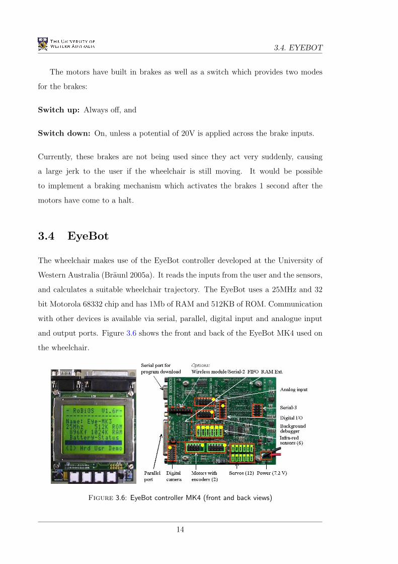
3.4 EyeBot
The wheelchair makes use of the EyeBot controller developed at the University of
Western Australia (Braunl 2005a). It reads the inputs from the user and the sensors,
and calculates a suitable wheelchair trajectory. The EyeBot uses a 25MHz and 32
bit Motorola 68332 chip and has 1Mb of RAM and 512KB of ROM. Communication
with other devices is available via serial, parallel, digital input and analogue input
and output ports. Figure 3.6 shows the front and back of the EyeBot MK4 used on
the wheelchair.
Figure 3.6: EyeBot controller MK4 (front and back views)
14
CHAPTER 3. HARDWARE
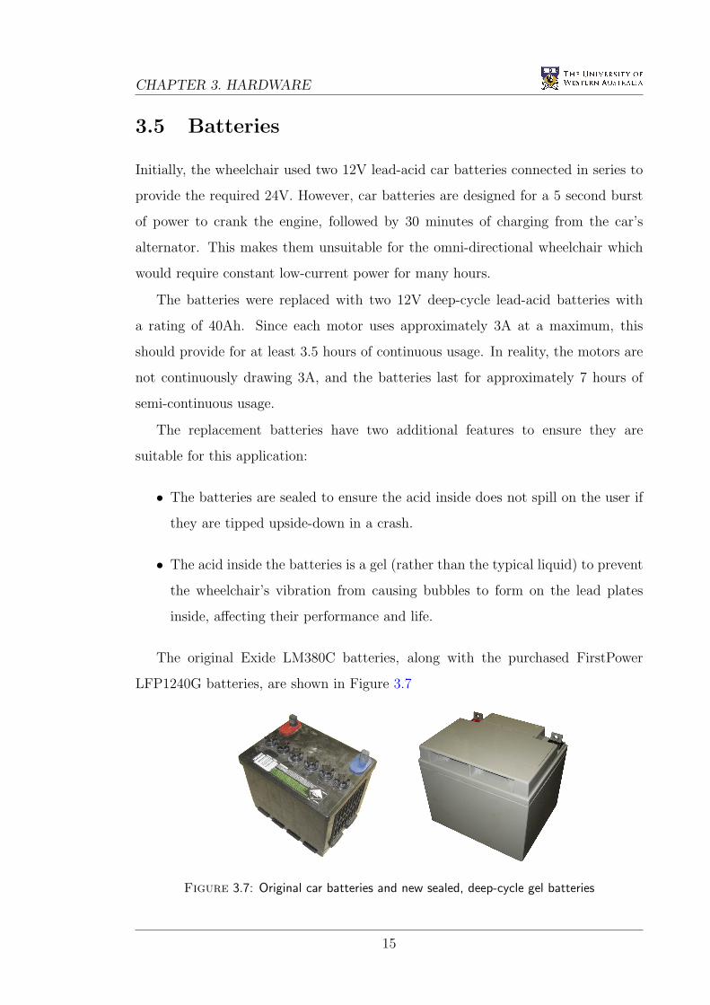
3.5 Batteries
Initially, the wheelchair used two 12V lead-acid car batteries connected in series to
provide the required 24V. However, car batteries are designed for a 5 second burst
of power to crank the engine, followed by 30 minutes of charging from the car’s
alternator. This makes them unsuitable for the omni-directional wheelchair which
would require constant low-current power for many hours.
The batteries were replaced with two 12V deep-cycle lead-acid batteries with
a rating of 40Ah. Since each motor uses approximately 3A at a maximum, this
should provide for at least 3.5 hours of continuous usage. In reality, the motors are
not continuously drawing 3A, and the batteries last for approximately 7 hours of
semi-continuous usage.
The replacement batteries have two additional features to ensure they are
suitable for this application:
• The batteries are sealed to ensure the acid inside does not spill on the user if
they are tipped upside-down in a crash.
• The acid inside the batteries is a gel (rather than the typical liquid) to prevent
the wheelchair’s vibration from causing bubbles to form on the lead plates
inside, affecting their performance and life.
The original Exide LM380C batteries, along with the purchased FirstPower
LFP1240G batteries, are shown in Figure 3.7
Figure 3.7: Original car batteries and new sealed, deep-cycle gel batteries
15
3.6. POSITION SENSITIVE DEVICES
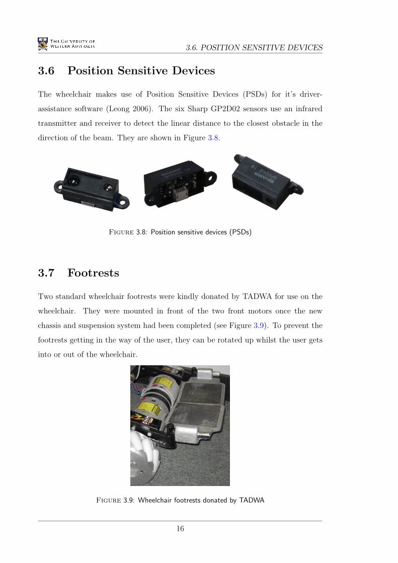
3.6 Position Sensitive Devices
The wheelchair makes use of Position Sensitive Devices (PSDs) for it’s driver-
assistance software (Leong 2006). The six Sharp GP2D02 sensors use an infrared
transmitter and receiver to detect the linear distance to the closest obstacle in the
direction of the beam. They are shown in Figure 3.8.
Figure 3.8: Position sensitive devices (PSDs)
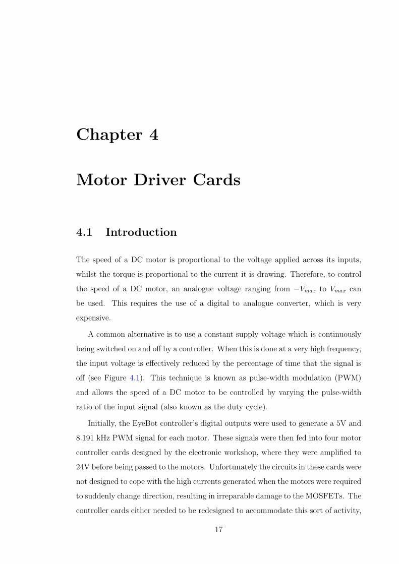
3.7 Footrests
Two standard wheelchair footrests were kindly donated by TADWA for use on the
wheelchair. They were mounted in front of the two front motors once the new
chassis and suspension system had been completed (see Figure 3.9). To prevent the
footrests getting in the way of the user, they can be rotated up whilst the user gets
into or out of the wheelchair.
Figure 3.9: Wheelchair footrests donated by TADWA
16
Chapter 4
Motor Driver Cards
4.1 Introduction
The speed of a DC motor is proportional to the voltage applied across its inputs,
whilst the torque is proportional to the current it is drawing. Therefore, to control
the speed of a DC motor, an analogue voltage ranging from −Vmax to Vmax can
be used. This requires the use of a digital to analogue converter, which is very
expensive.
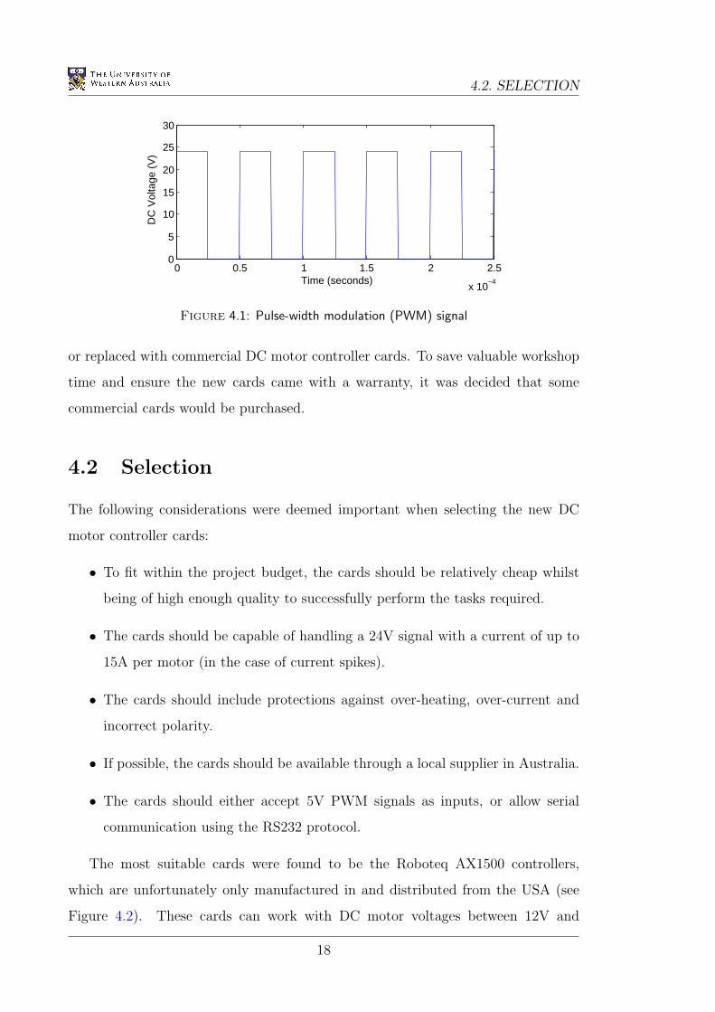
A common alternative is to use a constant supply voltage which is continuously
being switched on and off by a controller. When this is done at a very high frequency,
the input voltage is effectively reduced by the percentage of time that the signal is
off (see Figure 4.1). This technique is known as pulse-width modulation (PWM)
and allows the speed of a DC motor to be controlled by varying the pulse-width
ratio of the input signal (also known as the duty cycle).
Initially, the EyeBot controller’s digital outputs were used to generate a 5V and
8.191 kHz PWM signal for each motor. These signals were then fed into four motor
controller cards designed by the electronic workshop, where they were amplified to
24V before being passed to the motors. Unfortunately the circuits in these cards were
not designed to cope with the high currents generated when the motors were required
to suddenly change direction, resulting in irreparable damage to the MOSFETs. The
controller cards either needed to be redesigned to accommodate this sort of activity,
17
4.2. SELECTION
0 0.5 1 1.5 2 2.5
x 10−4
0
5
10
15
20
25
30
Time (seconds)
DC
Vol
tage
(V
)
Figure 4.1: Pulse-width modulation (PWM) signal
or replaced with commercial DC motor controller cards. To save valuable workshop
time and ensure the new cards came with a warranty, it was decided that some
commercial cards would be purchased.
4.2 Selection
The following considerations were deemed important when selecting the new DC
motor controller cards:
• To fit within the project budget, the cards should be relatively cheap whilst
being of high enough quality to successfully perform the tasks required.
• The cards should be capable of handling a 24V signal with a current of up to
15A per motor (in the case of current spikes).
• The cards should include protections against over-heating, over-current and
incorrect polarity.
• If possible, the cards should be available through a local supplier in Australia.
• The cards should either accept 5V PWM signals as inputs, or allow serial
communication using the RS232 protocol.
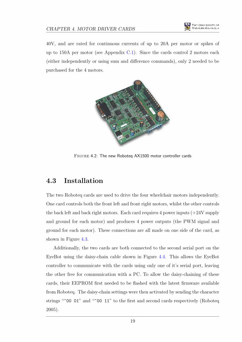
The most suitable cards were found to be the Roboteq AX1500 controllers,
which are unfortunately only manufactured in and distributed from the USA (see
Figure 4.2). These cards can work with DC motor voltages between 12V and
18
CHAPTER 4. MOTOR DRIVER CARDS
40V, and are rated for continuous currents of up to 20A per motor or spikes of
up to 150A per motor (see Appendix C.1). Since the cards control 2 motors each
(either independently or using sum and difference commands), only 2 needed to be
purchased for the 4 motors.
Figure 4.2: The new Roboteq AX1500 motor controller cards
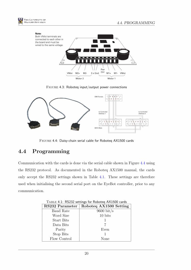
4.3 Installation
The two Roboteq cards are used to drive the four wheelchair motors independently.
One card controls both the front left and front right motors, whilst the other controls
the back left and back right motors. Each card requires 4 power inputs (+24V supply
and ground for each motor) and produces 4 power outputs (the PWM signal and
ground for each motor). These connections are all made on one side of the card, as
shown in Figure 4.3.
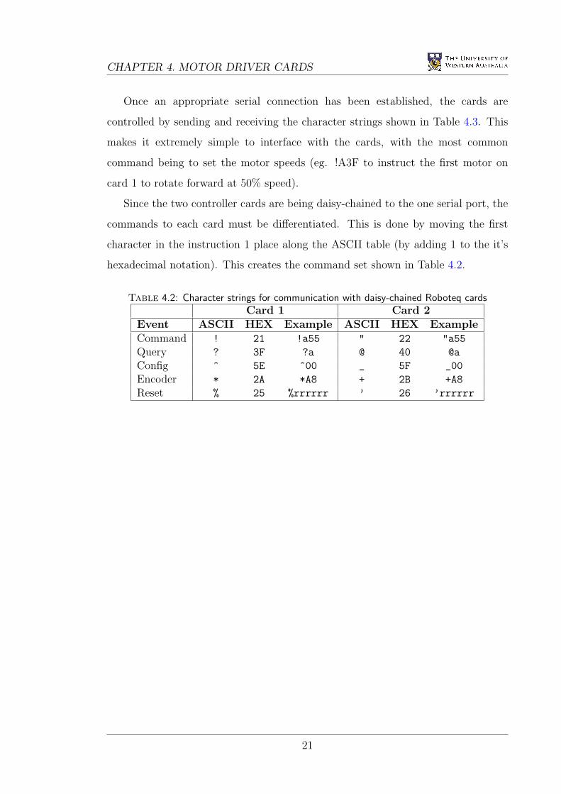
Additionally, the two cards are both connected to the second serial port on the
EyeBot using the daisy-chain cable shown in Figure 4.4. This allows the EyeBot
controller to communicate with the cards using only one of it’s serial port, leaving
the other free for communication with a PC. To allow the daisy-chaining of these
cards, their EEPROM first needed to be flashed with the latest firmware available
from Roboteq. The daisy-chain settings were then activated by sending the character
strings “^00 01” and “^00 11” to the first and second cards respectively (Roboteq
2005).
19
4.4. PROGRAMMING
AX1500 Quick Start
10 AX1500 Motor Controller User’s Manual Version 1.7b. November 3, 2005
Locating the Connectors
Take a moment to familiarize yourself with the controller’s connectors.
The front side (shown in Figure 1) contains the Power/Status LED and the 15-pin connector
to the R/C or microcomputer, as well as connections to optional switches and sensors.
Note: The Status LED is not used in version 1.7b of the controller’s software.
At the back of the controller (shown in the figure below) are located all the terminals that
must be connected to the batteries and the motors.
Status LED
FIGURE 1. AX1500 Controller Front View
Power LED
Connector to Receiver/Controls
and sensors
VMot
Motor 2 Motor 1
M2+ M1+ M1- VMotM2- 3 x Gnd
Pwr
Ctrl
FIGURE 2. AX1500 Controller Rear View
Note:
Both VMot terminals are
connected to each other in
the board and must be
wired to the same voltage.
Figure 4.3: Roboteq input/output power connections
AX3500 Motor Controller User’s Manual 87
Command Set
Command Set
Each controller echoes every character it receives.
Controller 0 recognizes the standard commands (e.g !a55, ?a ...) ignores the others.
Controller 1 recognizes commands+1 (see ASCII table: !+1 = ", ?+1 = @). E.g "a55, @a
ignores the rest
Inportant Notics
Since a “+” is a normal response of the controller after accepting a command, con-
troller at address 1 must be first in the daisy chain. If placed second, it will interpret
the “+” issued by the first controller as the start of a new command and cause an
error.
Command Latency and Delay
This scheme introduces a 1 character latency (~1ms). Furthermore the 9600bps bandwidth
must now be shared by two or more controllers.
TABLE 17.
ASCII HEX ASCII HEX Examples
Command ! 21 “ 22 !a55, “B7F
Query ? 3F @ 40 ?a, @p
Config ^ 5E _ 5F ^00, _01
Encoder * 2A + 2B *A8, +A9
Reset % 25 ‘ 26 %rrrrrr, ‘rrrrrr
1
15
6DB9 Female
DB15 Male
to Controller
Address 0
to Controller
Address 1
Tx
Tx
Rx
Rx
9
8
915
18
915
FIGURE 2. Daisy Chained RS232 Cable for two controllers
Figure 4.4: Daisy-chain serial cable for Roboteq AX1500 cards
4.4 Programming
Communication with the cards is done via the serial cable shown in Figure 4.4 using
the RS232 protocol. As documented in the Roboteq AX1500 manual, the cards
only accept the RS232 settings shown in Table 4.1. These settings are therefore
used when initialising the second serial port on the EyeBot controller, prior to any
communication.
Table 4.1: RS232 settings for Roboteq AX1500 cardsRS232 Parameter Roboteq AX1500 Setting
Baud Rate 9600 bit/sWord Size 10 bitsStart Bits 1Data Bits 7
Parity EvenStop Bits 1
Flow Control None
20
CHAPTER 4. MOTOR DRIVER CARDS
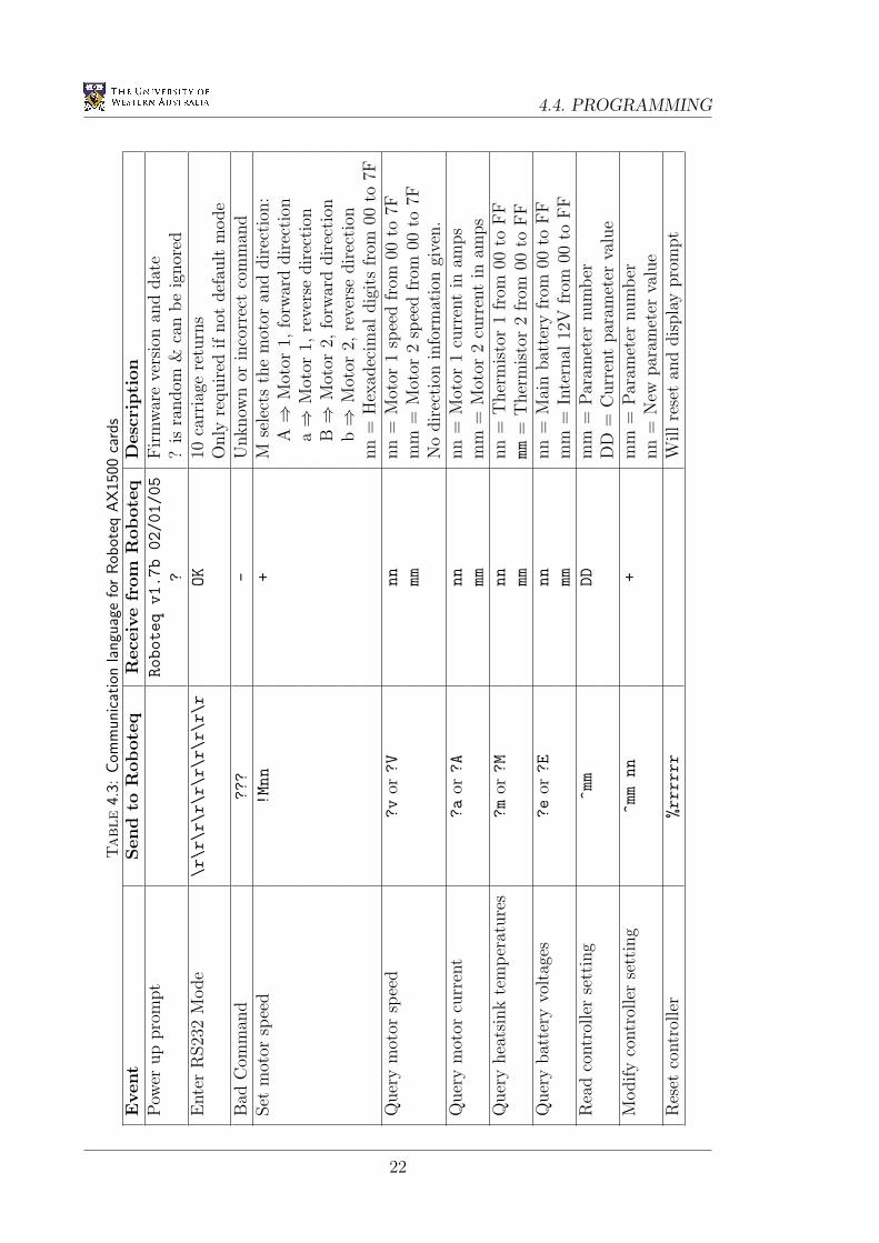
Once an appropriate serial connection has been established, the cards are
controlled by sending and receiving the character strings shown in Table 4.3. This
makes it extremely simple to interface with the cards, with the most common
command being to set the motor speeds (eg. !A3F to instruct the first motor on
card 1 to rotate forward at 50% speed).
Since the two controller cards are being daisy-chained to the one serial port, the
commands to each card must be differentiated. This is done by moving the first
character in the instruction 1 place along the ASCII table (by adding 1 to the it’s
hexadecimal notation). This creates the command set shown in Table 4.2.
Table 4.2: Character strings for communication with daisy-chained Roboteq cardsCard 1 Card 2
Event ASCII HEX Example ASCII HEX ExampleCommand ! 21 !a55 " 22 "a55
Query ? 3F ?a @ 40 @a
Config ^ 5E ^00 _ 5F _00
Encoder * 2A *A8 + 2B +A8
Reset % 25 %rrrrrr ’ 26 ’rrrrrr
21
4.4. PROGRAMMINGTable
4.3:
Com
munic
atio
nla
ngu
age
for
Rob
oteq
AX
1500
card
sEvent
Send
toR
obote
qR
ece
ive
from
Robote
qD
esc
ripti
on
Pow
erup
pro
mpt
Roboteq
v1.7b
02/01/05
Fir
mw
are
vers
ion
and
dat
e?
?is
random
&ca
nbe
ignor
edE
nte
rR
S23
2M
ode
\r\r\r\r\r\r\r\r\r\r
OK
10ca
rria
gere
turn
sO
nly
requir
edif
not
def
ault
mode
Bad
Com
man
d???
-U
nknow
nor
inco
rrec
tco
mm
and
Set
mot
orsp
eed
!Mnn
+M
sele
cts
the
mot
oran
ddir
ecti
on:
A⇒
Mot
or1,
forw
ard
dir
ection
a⇒
Mot
or1,
reve
rse
direc
tion
B⇒
Mot
or2,
forw
ard
dir
ection
b⇒
Mot
or2,
reve
rse
direc
tion
nn
=H
exad
ecim
aldig
its
from
00to
7FQ
uer
ym
otor
spee
d?v
or?V
nn
nn
=M
otor
1sp
eed
from
00to
7Fmm
mm
=M
otor
2sp
eed
from
00to
7FN
odir
ecti
onin
form
atio
ngi
ven.
Quer
ym
otor
curr
ent
?a
or?A
nn
nn
=M
otor
1cu
rren
tin
amps
mm
mm
=M
otor
2cu
rren
tin
amps
Quer
yhea
tsin
kte
mper
ature
s?m
or?M
nn
nn
=T
her
mis
tor
1fr
om00
toFF
mm
mm
=T
her
mis
tor
2fr
om00
toFF
Quer
ybat
tery
volt
ages
?e
or?E
nn
nn
=M
ain
bat
tery
from
00to
FF
mm
mm
=In
tern
al12
Vfr
om00
toFF
Rea
dco
ntr
olle
rse
ttin
g^mm
DD
mm
=Par
amet
ernum
ber
DD
=C
urr
ent
par
amet
erva
lue
Modify
contr
olle
rse
ttin
g^mm
nn
+m
m=
Par
amet
ernum
ber
nn
=N
ewpar
amet
erva
lue
Res
etco
ntr
olle
r%rrrrrr
Willre
set
and
dis
pla
ypro
mpt
22
Chapter 5
Joystick
5.1 Introduction
Many people with disabilities rely on wheelchairs for use throughout their daily
life. As a result, a wheelchair’s control mechanism should be simple and accurate.
Unfortunately, controlling a vehicle with 3 degrees of freedom is not immediately
intuitive. Of the many human interface designs discussed in Section 2.3, a position-
sensing joystick is the most familiar and simple to use, and was therefore selected
for this wheelchair.
5.2 Selection
Joysticks come in all shapes and sizes, with many different features available. When
selecting the appropriate joystick for the wheelchair, two important considerations
were taken into account:
• Whether the joystick should be analogue or digital, and
• Whether the joystick should have 2 or 3 axes.
A digital joystick uses multiple on/off micro-switches to determine the direction
in which the stick is being pushed. Using such a joystick would require an
accompanying dial or pair of buttons to control the speed of the wheelchair.
Conversely, an analogue joystick (often) uses potentiometers to sense both the
23
5.2. SELECTION
magnitude and direction in which the stick is being pushed. In this way, the speed
of the wheelchair is directly proportional to the degree by which the stick has been
moved from it’s origin. Of the two methods, the former allows simpler joystick
control for disabled users with poor fine-motor skills, whilst the latter provides a
more intuitive interface.
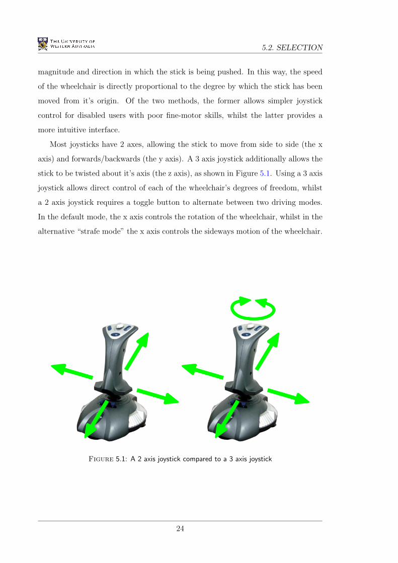
Most joysticks have 2 axes, allowing the stick to move from side to side (the x
axis) and forwards/backwards (the y axis). A 3 axis joystick additionally allows the
stick to be twisted about it’s axis (the z axis), as shown in Figure 5.1. Using a 3 axis
joystick allows direct control of each of the wheelchair’s degrees of freedom, whilst
a 2 axis joystick requires a toggle button to alternate between two driving modes.
In the default mode, the x axis controls the rotation of the wheelchair, whilst in the
alternative “strafe mode” the x axis controls the sideways motion of the wheelchair.
Figure 5.1: A 2 axis joystick compared to a 3 axis joystick
24
CHAPTER 5. JOYSTICK
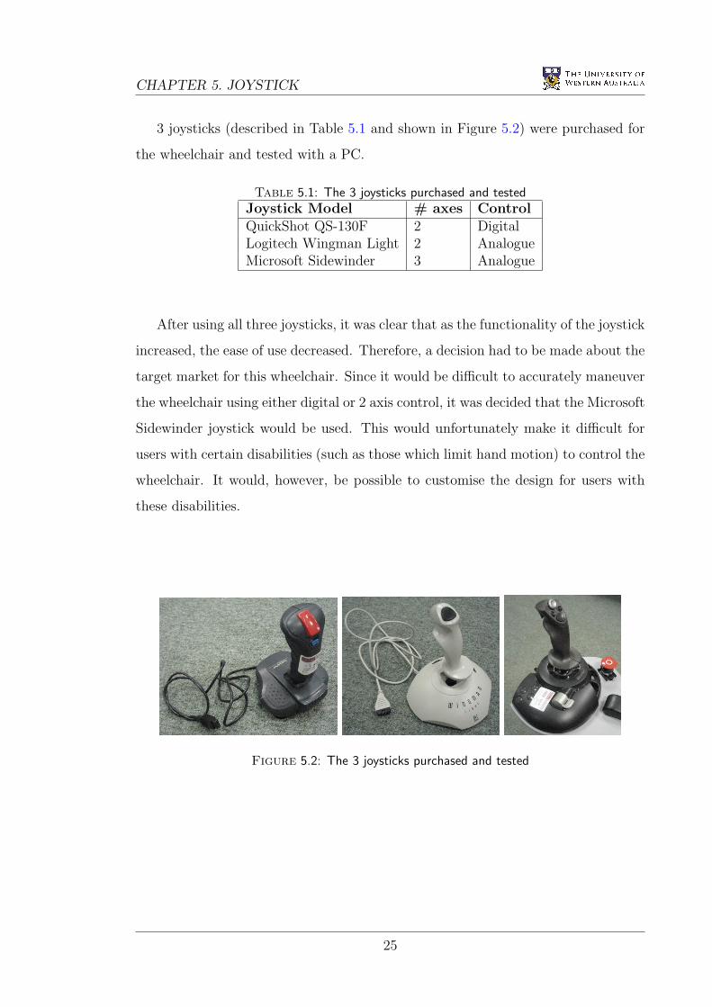
3 joysticks (described in Table 5.1 and shown in Figure 5.2) were purchased for
the wheelchair and tested with a PC.
Table 5.1: The 3 joysticks purchased and testedJoystick Model # axes ControlQuickShot QS-130F 2 DigitalLogitech Wingman Light 2 AnalogueMicrosoft Sidewinder 3 Analogue
After using all three joysticks, it was clear that as the functionality of the joystick
increased, the ease of use decreased. Therefore, a decision had to be made about the
target market for this wheelchair. Since it would be difficult to accurately maneuver
the wheelchair using either digital or 2 axis control, it was decided that the Microsoft
Sidewinder joystick would be used. This would unfortunately make it difficult for
users with certain disabilities (such as those which limit hand motion) to control the
wheelchair. It would, however, be possible to customise the design for users with
these disabilities.
Figure 5.2: The 3 joysticks purchased and tested
25
5.3. INSTALLATION
5.3 Installation
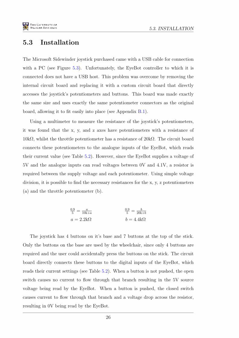
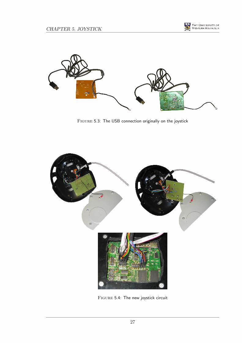
The Microsoft Sidewinder joystick purchased came with a USB cable for connection
with a PC (see Figure 5.3). Unfortunately, the EyeBot controller to which it is
connected does not have a USB host. This problem was overcome by removing the
internal circuit board and replacing it with a custom circuit board that directly
accesses the joystick’s potentiometers and buttons. This board was made exactly
the same size and uses exactly the same potentiometer connectors as the original
board, allowing it to fit easily into place (see Appendix B.1).
Using a multimeter to measure the resistance of the joystick’s potentiometers,
it was found that the x, y, and z axes have potentiometers with a resistance of
10kΩ, whilst the throttle potentiometer has a resistance of 20kΩ. The circuit board
connects these potentiometers to the analogue inputs of the EyeBot, which reads
their current value (see Table 5.2). However, since the EyeBot supplies a voltage of
5V and the analogue inputs can read voltages between 0V and 4.1V, a resistor is
required between the supply voltage and each potentiometer. Using simple voltage
division, it is possible to find the necessary resistances for the x, y, z potentiometers
(a) and the throttle potentiometer (b).
0.95
= a10k+a
0.95
= b20k+b
a = 2.2kΩ b = 4.4kΩ
The joystick has 4 buttons on it’s base and 7 buttons at the top of the stick.
Only the buttons on the base are used by the wheelchair, since only 4 buttons are
required and the user could accidentally press the buttons on the stick. The circuit
board directly connects these buttons to the digital inputs of the EyeBot, which
reads their current settings (see Table 5.2). When a button is not pushed, the open
switch causes no current to flow through that branch resulting in the 5V source
voltage being read by the EyeBot. When a button is pushed, the closed switch
causes current to flow through that branch and a voltage drop across the resistor,
resulting in 0V being read by the EyeBot.
26
CHAPTER 5. JOYSTICK
Figure 5.3: The USB connection originally on the joystick
Figure 5.4: The new joystick circuit
27
5.4. PROGRAMMING
Table 5.2: EyeBot I/O pins used
Signal Wire Colour EyeBot PinX Axis Yellow Analogue Input 5Y Axis Green Analogue Input 6Z Axis Brown Analogue Input 7
Throttle Grey Analogue Input 8Button 5 Blue Digital I/O 9Button 6 Thin Black Digital I/O 10Button 7 Purple Digital I/O 11Button 8 Orange Digital I/O 12
+5V Red Digital I/O 13Ground Thick Black Digital I/O 16
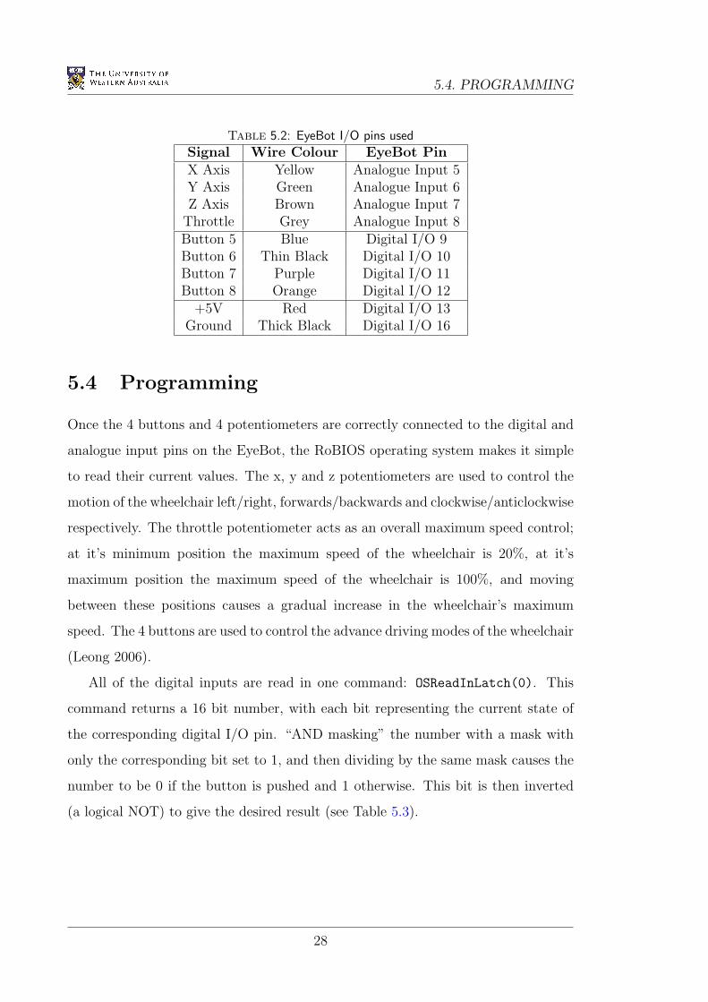
5.4 Programming
Once the 4 buttons and 4 potentiometers are correctly connected to the digital and
analogue input pins on the EyeBot, the RoBIOS operating system makes it simple
to read their current values. The x, y and z potentiometers are used to control the
motion of the wheelchair left/right, forwards/backwards and clockwise/anticlockwise
respectively. The throttle potentiometer acts as an overall maximum speed control;
at it’s minimum position the maximum speed of the wheelchair is 20%, at it’s
maximum position the maximum speed of the wheelchair is 100%, and moving
between these positions causes a gradual increase in the wheelchair’s maximum
speed. The 4 buttons are used to control the advance driving modes of the wheelchair
(Leong 2006).
All of the digital inputs are read in one command: OSReadInLatch(0). This
command returns a 16 bit number, with each bit representing the current state of
the corresponding digital I/O pin. “AND masking” the number with a mask with
only the corresponding bit set to 1, and then dividing by the same mask causes the
number to be 0 if the button is pushed and 1 otherwise. This bit is then inverted
(a logical NOT) to give the desired result (see Table 5.3).
28
CHAPTER 5. JOYSTICK
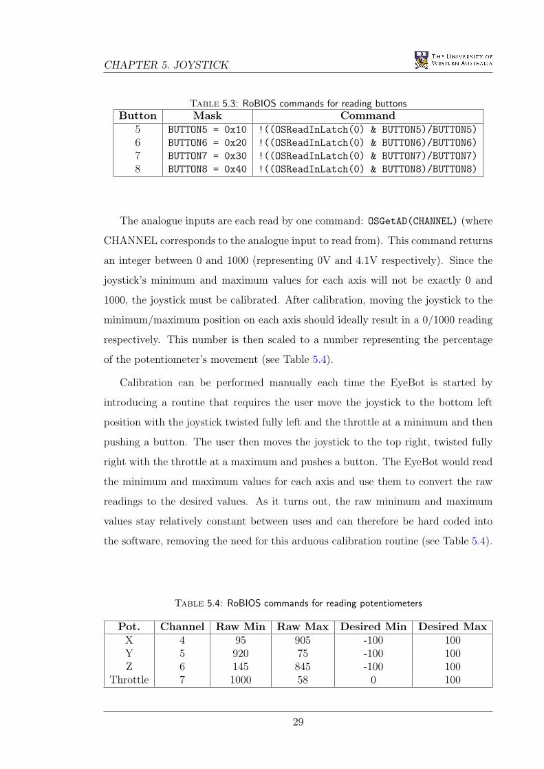
Table 5.3: RoBIOS commands for reading buttonsButton Mask Command
5 BUTTON5 = 0x10 !((OSReadInLatch(0) & BUTTON5)/BUTTON5)
6 BUTTON6 = 0x20 !((OSReadInLatch(0) & BUTTON6)/BUTTON6)
7 BUTTON7 = 0x30 !((OSReadInLatch(0) & BUTTON7)/BUTTON7)
8 BUTTON8 = 0x40 !((OSReadInLatch(0) & BUTTON8)/BUTTON8)
The analogue inputs are each read by one command: OSGetAD(CHANNEL) (where
CHANNEL corresponds to the analogue input to read from). This command returns
an integer between 0 and 1000 (representing 0V and 4.1V respectively). Since the
joystick’s minimum and maximum values for each axis will not be exactly 0 and
1000, the joystick must be calibrated. After calibration, moving the joystick to the
minimum/maximum position on each axis should ideally result in a 0/1000 reading
respectively. This number is then scaled to a number representing the percentage
of the potentiometer’s movement (see Table 5.4).
Calibration can be performed manually each time the EyeBot is started by
introducing a routine that requires the user move the joystick to the bottom left
position with the joystick twisted fully left and the throttle at a minimum and then
pushing a button. The user then moves the joystick to the top right, twisted fully
right with the throttle at a maximum and pushes a button. The EyeBot would read
the minimum and maximum values for each axis and use them to convert the raw
readings to the desired values. As it turns out, the raw minimum and maximum
values stay relatively constant between uses and can therefore be hard coded into
the software, removing the need for this arduous calibration routine (see Table 5.4).
Table 5.4: RoBIOS commands for reading potentiometers
Pot. Channel Raw Min Raw Max Desired Min Desired MaxX 4 95 905 -100 100Y 5 920 75 -100 100Z 6 145 845 -100 100
Throttle 7 1000 58 0 100
29

5.4. PROGRAMMING
After calibration, the joystick input values are finally adjusted using threshold
values on each axis. This causes the input from an axis to be taken as zero unless
it is above a specified (and customisable) value. This is required for three reasons:
• The joystick is extremely sensitive around it’s origin, and any small accidental
movements would cause the wheelchair to drive.
• People with disabilities may have difficulty holding the joystick perfectly still
at the origin without shaking it.
• By thresholding each axis individually, driving directly forward is also made
easier by preventing a small component of the wheelchair’s velocity from being
in the sideways direction.
After testing, it was found that a threshold value of 15% was optimal for most
wheelchair users on each axis.
30
Chapter 6
Low Level Driving Routines
6.1 Introduction
For any driving robot, the low-level driving routines are the simple components of
the onboard software that determine the desired driving positions, velocities and/or
accelerations. This involves interfacing with all input and feedback devices on the
vehicle and calculating the required motor speeds before sending them to the motors.
In our current wheelchair design, there are 3 pieces of hardware with which the
low-level driving routines must communicate:
• the 3-axis joystick to read the human input,
• the infra-red remote control receiver as an alternative means of human input,
and
• the motor controller cards to ensure the correct motor speeds are achieved.
Higher level driving routines are also being developed which make use of
the wheelchair’s onboard position-sensitive devices (PSDs) to perform automatic
functions such as door-driving, wall following and obstacle avoidance (Leong 2006).
31
6.2. DESIGN
6.2 Design
The software has been written entirely in the C programming language and compiled
using the gcc68 compiler for the Motorola HC68332 chip (Braunl 2005a). Although
C itself is not an object-oriented language, it can be made modular by using separate
text files for the different software components. Header files are used to define the
necessary variables and functions, as well as include documentation and comments
on their use. These files have the .h prefix (eg. ODW.h). The bulk of the code is
included in the C source files, with filenames using the .c prefix (eg. ODW.c).
The wheelchair’s code has 4 main components or modules, each modelled around
the hardware with which it is interfacing. A brief description of each component is
provided below.
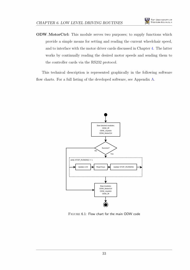
ODW: This component of the software includes the main function which initially
starts the desired modules. Once these modules have been successfully started,
the main function continually loops and updates the LCD display, whilst
reading any EyeBot key inputs. When key 4 is pressed, the program stops
the running modules and exits gracefully.
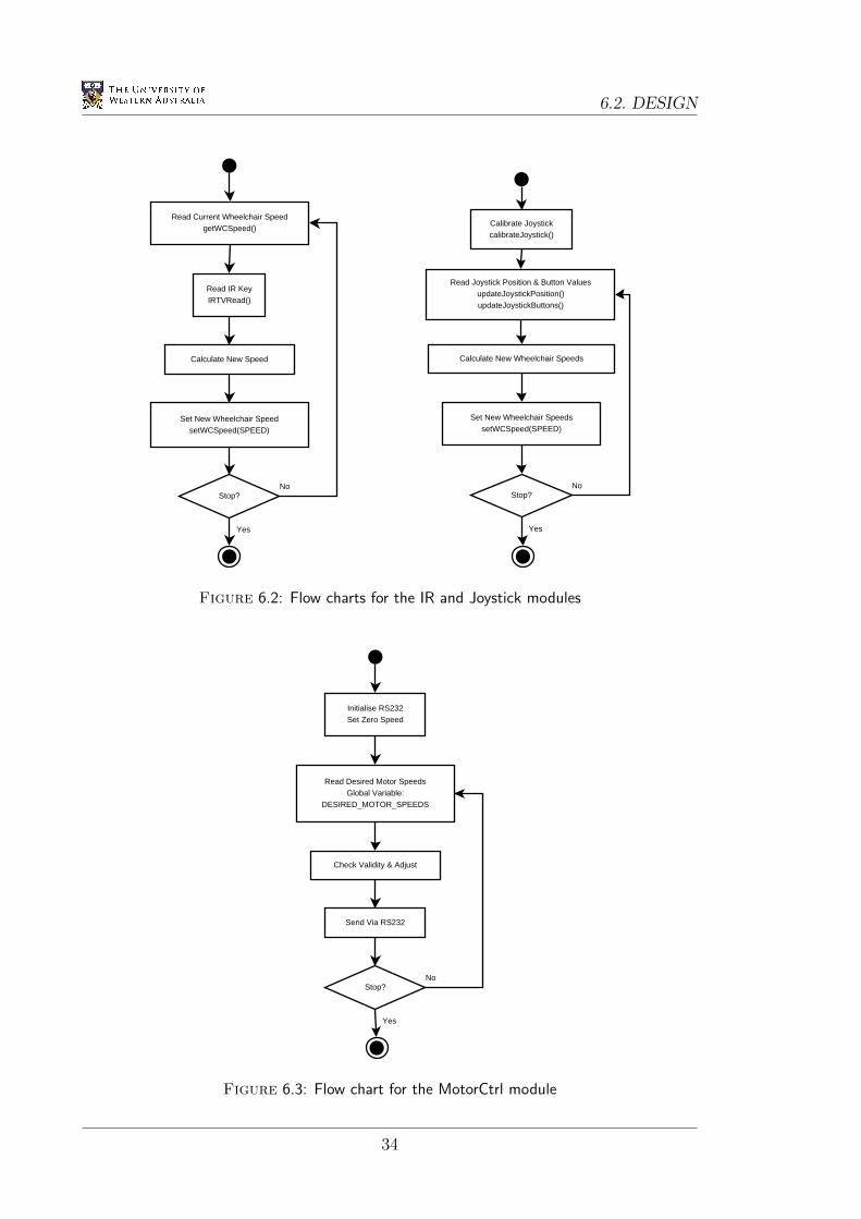
ODW IR: This module interfaces with the infra-red remote control receiver,
allowing the wheelchair to be controlled by a Nokia remote control. The
module initialises the receiver and waits for a key input. When a key input is
received, the appropriate action (defined in the corresponding header file) is
taken. It is important to note that the functionality of this module is effectively
destroyed if the Joystick module is also activated.
ODW Joystick: This module interfaces with the modified 3-axis Microsoft Sidewinder
joystick discussed in Chapter 5. When started, the module first calibrates the
joystick and then continually reads the joystick’s current position and button
values. This data is converted into the appropriate motor speeds using the
inverseKinematics function, which are then set using the setWCSpeed function
(both of which are found in the ODW MotorCtrl module). The button values
can also be used to activate the advanced driving routines (Leong 2006).
32
CHAPTER 6. LOW LEVEL DRIVING ROUTINES
ODW MotorCtrl: This module serves two purposes; to supply functions which
provide a simple means for setting and reading the current wheelchair speed,
and to interface with the motor driver cards discussed in Chapter 4. The latter
works by continually reading the desired motor speeds and sending them to
the controller cards via the RS232 protocol.
This technical description is represented graphically in the following software
flow charts. For a full listing of the developed software, see Appendix A.
Start desired modules:ODW_IR
ODW_JoystickODW_MotorCtrl
Success?
Stop modules:ODW_MotorCtrlODW_Joystick
ODW_IR
while STOP_RUNNING != 1
Update LCD Read Keys Update STOP_RUNNING
Yes
No
Figure 6.1: Flow chart for the main ODW code
33
6.2. DESIGN
Read Current Wheelchair SpeedgetWCSpeed()
Read IR KeyIRTVRead()
Calculate New Speed
Set New Wheelchair SpeedsetWCSpeed(SPEED)
Stop?No
Yes
Read Joystick Position & Button ValuesupdateJoystickPosition()updateJoystickButtons()
Calculate New Wheelchair Speeds
Set New Wheelchair SpeedssetWCSpeed(SPEED)
Calibrate JoystickcalibrateJoystick()
Stop?No
Yes
Figure 6.2: Flow charts for the IR and Joystick modules
Read Desired Motor SpeedsGlobal Variable:
DESIRED_MOTOR_SPEEDS
Check Validity & Adjust
Send Via RS232
Initialise RS232Set Zero Speed
Stop?No
Yes
Figure 6.3: Flow chart for the MotorCtrl module
34
Chapter 7
Suspension System
7.1 Introduction
At the beginning of 2006, the omni-directional wheelchair had no suspension system;
the wheels were directly coupled to the motors which were in turn directly mounted
onto the chassis. This initial setup was only intended to be a temporary solution,
until a superior design was developed.
As discussed in Section 3.2.2, the Mecanum wheels used on the omni-directional
wheelchair cause a large degree of slip during it’s normal operation. This makes
the wheelchair difficult to drive accurately, and deprecates any feedback that could
be obtained from shaft encoders. Part of this slip could be attributed to the rigid
design, which would cause only 3 of the 4 wheels to be in contact with the ground
when driving on uneven terrain. This would theoretically cause the wheelchair to
drive at 45 to the design direction.
This problem was overcome by designing and building a suspension system for
the wheelchair. Under the weight of the wheelchair and it’s user, each wheel is now
being constantly pushed down to the ground. In addition, the wheelchair is more
capable of handling rough terrain such as grassed or paved areas without causing
excessive user discomfort.
One final problem that was overcome by the inclusion of this system was the
issue of vibrations felt by the user during medium to high speed driving. These
35
7.2. DESIGN
vibrations could mainly be attributed to the minor machining inaccuracies of the
Mecanum wheels which resulted in a sudden jerk each time the roller in contact the
ground was alternated. Since the rollers were made of an inflexible plastic and there
was no suspension built into the design, the user would be left feeling these effects.
This was found to be particularly bad when driving on a rough terrain.
7.2 Design
Suspension systems often rely on a spring and a damper used in combination to
absorb both the small vibrations and the large movements. The spring acts as the
main absorber, whilst the damper acts to mitigate the oscillatory effects over time.
Many bicycle designs now include a small spring/damper shock absorber directly
below the seat in the main frame. These shock absorbers are available in many
different sizes, with varying spring stiffness and damping coefficients to match.
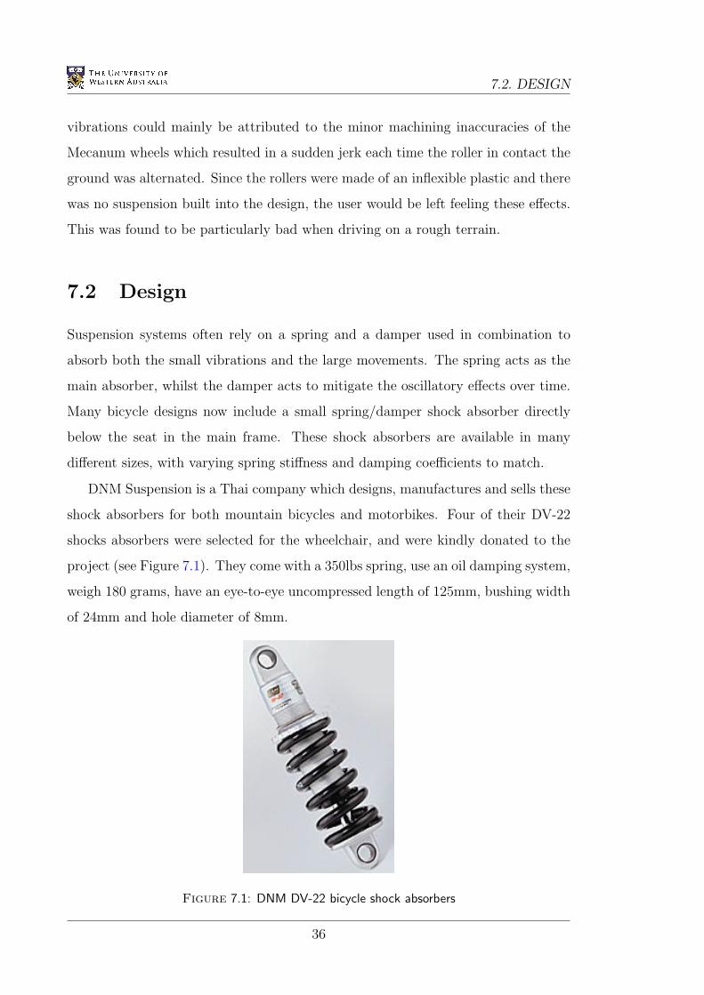
DNM Suspension is a Thai company which designs, manufactures and sells these
shock absorbers for both mountain bicycles and motorbikes. Four of their DV-22
shocks absorbers were selected for the wheelchair, and were kindly donated to the
project (see Figure 7.1). They come with a 350lbs spring, use an oil damping system,
weigh 180 grams, have an eye-to-eye uncompressed length of 125mm, bushing width
of 24mm and hole diameter of 8mm.
Figure 7.1: DNM DV-22 bicycle shock absorbers
36
CHAPTER 7. SUSPENSION SYSTEM
Since the wheels mount directly onto the shafts of the motors, these shock
absorbers are placed between the main chassis and the motors. The chassis therefore
serves three purposes:
• it holds/contains the batteries, electronics, sensors and wiring,
• it acts as a base for the actual chair the user sits on, and
• it acts as a strong frame to hold the motors.
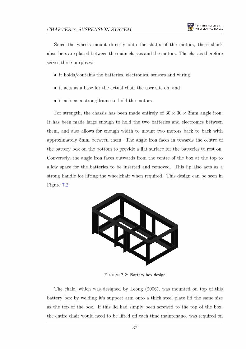
For strength, the chassis has been made entirely of 30 × 30 × 3mm angle iron.
It has been made large enough to hold the two batteries and electronics between
them, and also allows for enough width to mount two motors back to back with
approximately 5mm between them. The angle iron faces in towards the centre of
the battery box on the bottom to provide a flat surface for the batteries to rest on.
Conversely, the angle iron faces outwards from the centre of the box at the top to
allow space for the batteries to be inserted and removed. This lip also acts as a
strong handle for lifting the wheelchair when required. This design can be seen in
Figure 7.2.
Figure 7.2: Battery box design
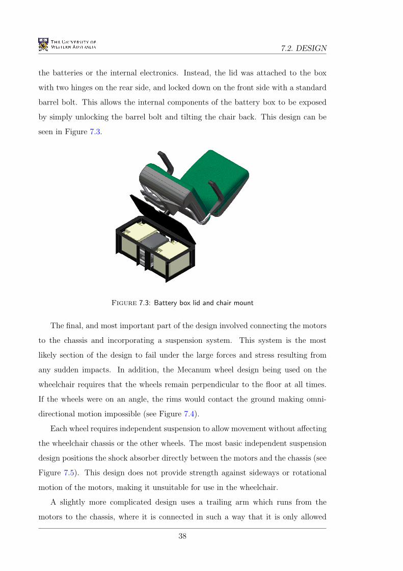
The chair, which was designed by Leong (2006), was mounted on top of this
battery box by welding it’s support arm onto a thick steel plate lid the same size
as the top of the box. If this lid had simply been screwed to the top of the box,
the entire chair would need to be lifted off each time maintenance was required on
37
7.2. DESIGN
the batteries or the internal electronics. Instead, the lid was attached to the box
with two hinges on the rear side, and locked down on the front side with a standard
barrel bolt. This allows the internal components of the battery box to be exposed
by simply unlocking the barrel bolt and tilting the chair back. This design can be
seen in Figure 7.3.
Figure 7.3: Battery box lid and chair mount
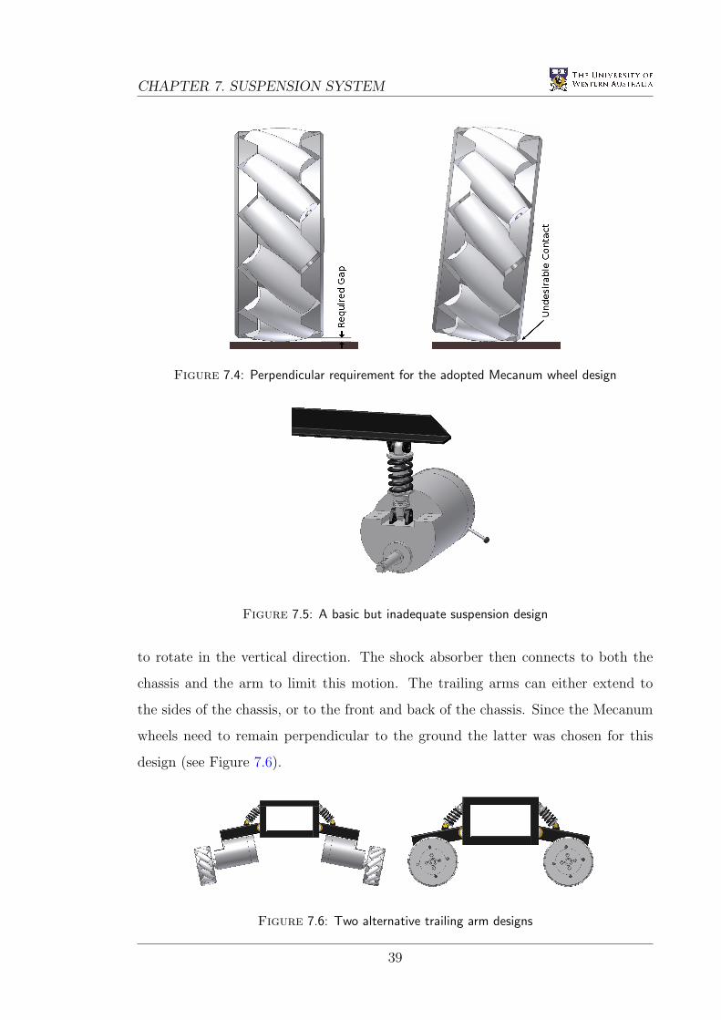
The final, and most important part of the design involved connecting the motors
to the chassis and incorporating a suspension system. This system is the most
likely section of the design to fail under the large forces and stress resulting from
any sudden impacts. In addition, the Mecanum wheel design being used on the
wheelchair requires that the wheels remain perpendicular to the floor at all times.
If the wheels were on an angle, the rims would contact the ground making omni-
directional motion impossible (see Figure 7.4).
Each wheel requires independent suspension to allow movement without affecting
the wheelchair chassis or the other wheels. The most basic independent suspension
design positions the shock absorber directly between the motors and the chassis (see
Figure 7.5). This design does not provide strength against sideways or rotational
motion of the motors, making it unsuitable for use in the wheelchair.
A slightly more complicated design uses a trailing arm which runs from the
motors to the chassis, where it is connected in such a way that it is only allowed
38
CHAPTER 7. SUSPENSION SYSTEM
Figure 7.4: Perpendicular requirement for the adopted Mecanum wheel design
Figure 7.5: A basic but inadequate suspension design
to rotate in the vertical direction. The shock absorber then connects to both the
chassis and the arm to limit this motion. The trailing arms can either extend to
the sides of the chassis, or to the front and back of the chassis. Since the Mecanum
wheels need to remain perpendicular to the ground the latter was chosen for this
design (see Figure 7.6).
Figure 7.6: Two alternative trailing arm designs
39
7.2. DESIGN
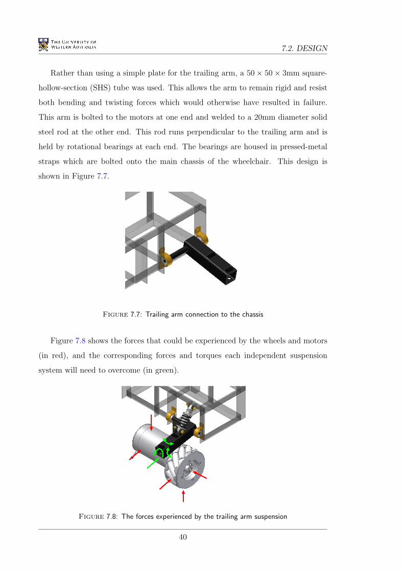
Rather than using a simple plate for the trailing arm, a 50× 50× 3mm square-
hollow-section (SHS) tube was used. This allows the arm to remain rigid and resist
both bending and twisting forces which would otherwise have resulted in failure.
This arm is bolted to the motors at one end and welded to a 20mm diameter solid
steel rod at the other end. This rod runs perpendicular to the trailing arm and is
held by rotational bearings at each end. The bearings are housed in pressed-metal
straps which are bolted onto the main chassis of the wheelchair. This design is
shown in Figure 7.7.
Figure 7.7: Trailing arm connection to the chassis
Figure 7.8 shows the forces that could be experienced by the wheels and motors
(in red), and the corresponding forces and torques each independent suspension
system will need to overcome (in green).
Figure 7.8: The forces experienced by the trailing arm suspension
40
CHAPTER 7. SUSPENSION SYSTEM
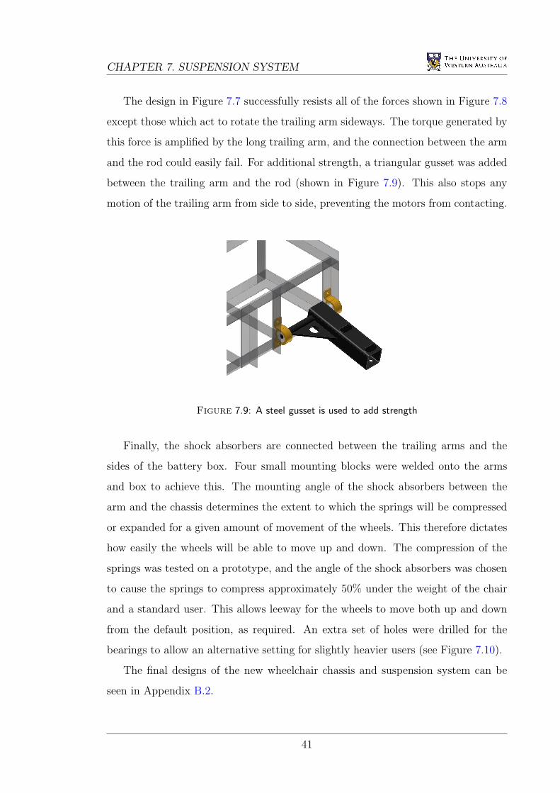
The design in Figure 7.7 successfully resists all of the forces shown in Figure 7.8
except those which act to rotate the trailing arm sideways. The torque generated by
this force is amplified by the long trailing arm, and the connection between the arm
and the rod could easily fail. For additional strength, a triangular gusset was added
between the trailing arm and the rod (shown in Figure 7.9). This also stops any
motion of the trailing arm from side to side, preventing the motors from contacting.
Figure 7.9: A steel gusset is used to add strength
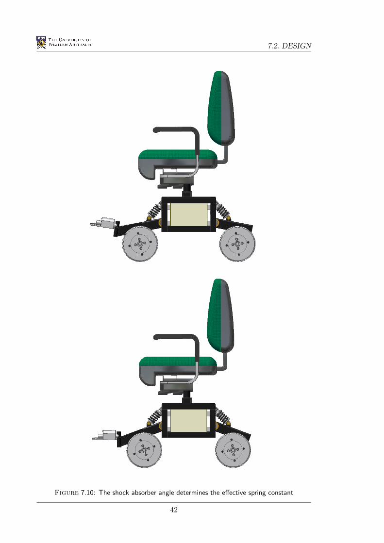
Finally, the shock absorbers are connected between the trailing arms and the
sides of the battery box. Four small mounting blocks were welded onto the arms
and box to achieve this. The mounting angle of the shock absorbers between the
arm and the chassis determines the extent to which the springs will be compressed
or expanded for a given amount of movement of the wheels. This therefore dictates
how easily the wheels will be able to move up and down. The compression of the
springs was tested on a prototype, and the angle of the shock absorbers was chosen
to cause the springs to compress approximately 50% under the weight of the chair
and a standard user. This allows leeway for the wheels to move both up and down
from the default position, as required. An extra set of holes were drilled for the
bearings to allow an alternative setting for slightly heavier users (see Figure 7.10).
The final designs of the new wheelchair chassis and suspension system can be
seen in Appendix B.2.
41
7.2. DESIGN
Figure 7.10: The shock absorber angle determines the effective spring constant
42
Chapter 8
Results, Testing and Simulation
8.1 Motor Control
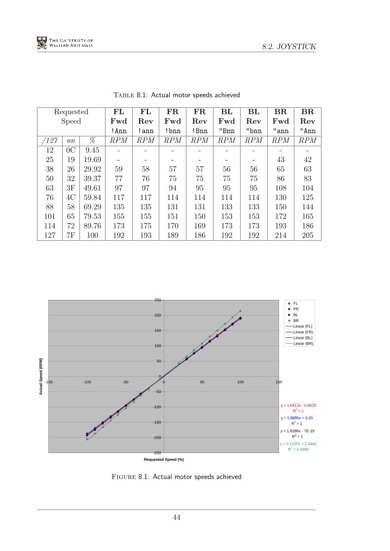
The speeds of the four independent DC motors on the wheelchair are now controlled
by the new Roboteq AX1500 controller cards. This is done by sending ASCII
characters through the daisy-chain serial cable using the RS232 protocol (see
Chapter 4). Tests were performed on the motors, by measuring the actual speeds
achieved for certain requested values. Even though no feedback is used to control
the motor speeds, they are in general very accurate. The test results can be seen in
Table 8.1 and Figure 8.1. If the motors were to become inaccurate in the future, it
would be possible to write simple software instructions to calibrate them.
8.2 Joystick
The 3-axis joystick installed in this project allows highly accurate control of each of
the wheelchair’s degrees of freedom. Although this style of joystick is new to most
users, the design is intuitive and easy to learn. To prevent accidental wheelchair
motion resulting from small movements of the stick near the zero position of an axis,
independent threshold values were implemented on each axis. These values can be
customised to also allow users with deteriorated fine-motor skills (such as those with
Parkinson’s disease) to use the joystick.
43
8.2. JOYSTICK
Table 8.1: Actual motor speeds achieved
Requested FL FL FR FR BL BL BR BRSpeed Fwd Rev Fwd Rev Fwd Rev Fwd Rev
!Ann !ann !bnn !Bnn "Bnn "bnn "ann "Ann
/127 nn % RPM RPM RPM RPM RPM RPM RPM RPM12 0C 9.45 - - - - - - - -25 19 19.69 - - - - - - 43 4238 26 29.92 59 58 57 57 56 56 65 6350 32 39.37 77 76 75 75 75 75 86 8363 3F 49.61 97 97 94 95 95 95 108 10476 4C 59.84 117 117 114 114 114 114 130 12588 58 69.29 135 135 131 131 133 133 150 144101 65 79.53 155 155 151 150 153 153 172 165114 72 89.76 173 175 170 169 173 173 193 186127 7F 100 192 193 189 186 192 192 214 205
y = 1.9412x - 0.0625
R2 = 1
y = 1.8895x + 0.25
R2 = 1
y = 1.9186x - 7E-15
R2 = 1
y = 2.1155x + 2.4444
R2 = 0.9999-250
-200
-150
-100
-50
0
50
100
150
200
250
-150 -100 -50 0 50 100 150
Requested Speed (%)
Act
ual
Sp
eed
(R
PM
)
FL
FR
BL
BR
Linear (FL)
Linear (FR)
Linear (BL)
Linear (BR)
Figure 8.1: Actual motor speeds achieved
44

CHAPTER 8. RESULTS, TESTING AND SIMULATION
Two programs were developed for testing the joystick on the EyeBot. The first
program, shown in Appendix A.13, prints both raw and calibrated joystick values
to the LCD, as well as the current values of the buttons (see Figure 8.3). This
program was used for the initial joystick testing and for finding the calibration
constants required to keep the joystick readings within the desired range. The
second program, shown in Appendix A.14, plots the current joystick values onto
a map on the LCD (see Figure 8.2). This program is useful for determining the
appropriate threshold values for each axis, and for visualising the actual joystick
position.
Figure 8.2: A textual joystick testing program
Figure 8.3: A graphical joystick testing program
45
8.3. SUSPENSION AND CHASSIS
8.3 Suspension and Chassis
After the installation of the trailing-arm suspension system, the wheelchair’s motion
was found to be much more accurate on uneven surfaces. Motions which used to
cause the Mecanum wheels to slip (such as sideways and diagonal driving) can now
be executed with a higher degree of accuracy. This is due to the wheels always being
pushed down to the ground by the springs in the shock absorbers. In addition, the
vibrations felt by the user when driving the wheelchair are now mostly absorbed by
the shock absorbers. This greatly improves the level of comfort for the user.
Maintenance can be performed on the wheelchair by simply unlocking the barrel-
bolt on top of the battery box, and tilting the entire chair backwards to expose the
electronic circuits and batteries. This prevents any injuries that would otherwise
result from the user lifting the entire chair off the battery box to access the internal
components.
An unexpected side-effect of the suspension system can be seen when the
wheelchair is driven directly to the side. These movements cause the springs on
the side away from the direction of motion to compress, resulting in a slight tilt
of the chair in this direction. This is due to the combination of the angular forces
from the Mecanum wheels, and cannot easily be overcome. Although this may at
first startle the user, there are no devastating effects and overtime the user learns
to anticipate it.
46
CHAPTER 8. RESULTS, TESTING AND SIMULATION
8.4 Modelling and Simulation
The new chassis and suspension system were designed with the aid of AutoDesk
Inventor version 10. Inventor is the 3D modelling version of AutoDesk’s popular
AutoCAD software, and is similar to other 3D CAD programs such as Solid Edge
and Solid Works. The model was used to ensure that all the components would
actually fit together as planned, and that the workshop would be able to get the
required access to all the nuts and bolts that needed to be fitted and tightened.
The model developed in AutoDesk Inventor was then converted to a Milkshape
3D model, developed by chUmbaLum sOft. This allowed the model to be used
in the EyeSim EyeBot simulation software developed at the University of Western
Australia (Braunl 2005b). A program called Deep Exploration, developed by Right
Hemisphere, was used to convert the Inventor assembly files (with extensions .iam
and .ipt) into a AutoDesk drawing interchange/exchange format file (with extension
.dxf). This file was then imported into Milkshape 3D where it was scaled, coloured,
and saved (with extension .ms3d) ready for use in EyeSim. A picture of the
wheelchair model in EyeSim is shown in Figure 8.4.
47
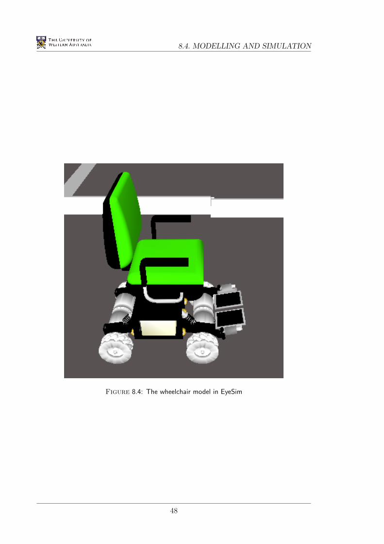
8.4. MODELLING AND SIMULATION
Figure 8.4: The wheelchair model in EyeSim
48
Chapter 9
Conclusion
9.1 Outcomes
The omni-directional wheelchair being developed at the University of Western
Australia’s Centre for Intelligent Information Processing Systems (CIIPS) allows
the user to easily manoeuvre in what would otherwise be an extremely complicated
environment. This project made improvements to the Mecanum wheels, batteries,
motor driver cards, human interface, control software, chassis and suspension
system.
These improvements transformed the partially working prototype into a fully
usable wheelchair (see Figure 9.1). The result is much higher driving accuracy and
a greatly improved overall experience for the user in both comfort and easy of use.
On the whole, the project was extremely successful and will provide a very solid test
bed for advanced driving and mapping projects in the future.
9.2 Recommendations
The following recommendations are made for future projects involving the wheelchair.
• Replace the current Mecanum wheels with an alternative material and design.
The current wheels are inherently slippery, and a rubbery material would
most likely prevent any slip from occurring. In addition to this, a soft rubber
49
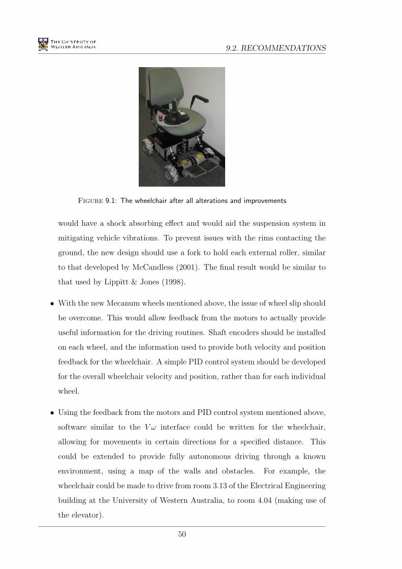
9.2. RECOMMENDATIONS
Figure 9.1: The wheelchair after all alterations and improvements
would have a shock absorbing effect and would aid the suspension system in
mitigating vehicle vibrations. To prevent issues with the rims contacting the
ground, the new design should use a fork to hold each external roller, similar
to that developed by McCandless (2001). The final result would be similar to
that used by Lippitt & Jones (1998).
• With the new Mecanum wheels mentioned above, the issue of wheel slip should
be overcome. This would allow feedback from the motors to actually provide
useful information for the driving routines. Shaft encoders should be installed
on each wheel, and the information used to provide both velocity and position
feedback for the wheelchair. A simple PID control system should be developed
for the overall wheelchair velocity and position, rather than for each individual
wheel.
• Using the feedback from the motors and PID control system mentioned above,
software similar to the V ω interface could be written for the wheelchair,
allowing for movements in certain directions for a specified distance. This
could be extended to provide fully autonomous driving through a known
environment, using a map of the walls and obstacles. For example, the
wheelchair could be made to drive from room 3.13 of the Electrical Engineering
building at the University of Western Australia, to room 4.04 (making use of
the elevator).
50
Bibliography
Airtrax. (2006). Omni-Directional Technology: Changing the way vehicles move,
[Online]. Available from: <http://www.airtrax.com/> [September 2006].
Braunl, T. 2003, Embedded Robotics: Mobile Robot Design and Applications with
Embedded Systems, Springer, New York.
Braunl, T. (2005a). EyeBot - Online Documentation, [Online],
The University of Western Australia. Available from:
<http://robotics.ee.uwa.edu.au/eyebot/index.html> [April 2006].
Braunl, T. (2005b). EyeSim - Mobile Robot Simulator, [Online],
The University of Western Australia. Available from:
<http://robotics.ee.uwa.edu.au/eyebot/doc/sim/sim.html> [September
2006].
Cooney, J.A., Xu, W.L., Bright, G. 2004, ‘Visual Dead-Reckoning for Motion
Control of a Mecanum-Wheeled Mobile Robot’, Mechatronics, vol. 14,
pp. 623–637.
Cooper, R.A., Jones, D.K., Fitzgerald, S., Boninger, M.L. & Albright, S.J. 2000,
‘Analysis of position and isometric joysticks for powered wheelchair driving’,
IEEE Transactions on Biomedical Engineering, vol. 47, pp. 902–910. Available
from: IEEE Xplore, [April 2006].
Coyle, E.D. 1995, ‘Electronic wheelchair controller designed for operation by hand-
operated joystick, ultrasonic noncontact head control and utterance from a
small word-command vocabulary’, IEEE Colloquium on New Developments
51
BIBLIOGRAPHY
in Electric Vehicles for Disabled Persons, pp. 3/1–3/4. Available from: IEEE
Xplore, [April 2006].
Dickerson, S. & Lapin, B. 1991, ‘Control of an omni-directional robotic vehicle with
Mecanum wheels’, Proceedings of the National Telesystems Conference, vol. 1,
pp. 323–328. Available from: IEEE Xplore, [April 2006].
Diegel, O., Badve, A., Bright, G., Potgieter, J. & Tlale, S. 2002, ‘Improved mecanum
wheel design for omni-directional robots’, Proceedings of the Australasian
Conference on Robotics and Automation, pp. 117–121.
Ding, D., Cooper, R.A., Spaeth, D. 2004, ‘Optimized joystick controller’, Proceedings
of the 26th Annual International Conference of the Engineering in Medicine and
Biology Society, vol. 2, pp. 4881–4883. Available from: IEEE Xplore, [April
2006].
Guo, S., Cooper, R.A., Boninger, M.L., Kwarciak, A. & Ammer, B. 2002,
‘Development of power wheelchair chin-operated force-sensing joystick’,
Proceedings of the Second Joint Engineering in Medicine and Biology, vol. 3,
pp. 2373–2374. Available from: IEEE Xplore, [April 2006].
Ilon, B.E. 1975, Wheels for a course stable selfpropelling vehicle movable in any
desirable direction on the ground or some other base, US Patent 3876255
Iwasaki, Y. 2005, Omni-Directional Wheelchair, Honours Thesis, The University of
Western Australia.
Jones, D.K., Cooper, R.A., Albright, S. & DiGiovine, M. 1998, ‘Powered wheelchair
driving performance using force- and position-sensing joysticks’, Proceedings
of the IEEE 24th Annual Northeast Bioengineering Conference, pp. 130–132.
Available from: IEEE Xplore, [April 2006].
Kamiuchi, S. & Maeyama, S. 2004, ‘A novel human interface of an omni-
directional wheelchair’, 13th IEEE International Workshop on Robot and
Human Interactive Communication, pp. 101–106. Available from: IEEE Xplore,
[April 2006].
52
BIBLIOGRAPHY
Kitagawa, L., Kobayashi, T., Beppu, T. & Terashima, K. 2001, ‘Semi-autonomous
obstacle avoidance of omnidirectional wheelchair by joystick impedance
control’, Proceedings of the IEEE/RSJ International Conference on Intelligent
Robots and Systems, vol. 4, pp. 2148–2153. Available from: IEEE Xplore, [April
2006].
Leong, M. 2006, Active User Omni-Directional Wheelchair, Honours Thesis, The
University of Western Australia.
Lippitt, T.C. & Jones, W.C. 1998, ‘OmniBot Mobile Base’, KSC Re-
search and Technology Report [Online], NASA, USA. Available from:
<http://rtreport.ksc.nasa.gov/techreports/98report/09-ar/ar06.html> [April
2006].
McCandless, A. 2001, Design and construction of a robot vehicle chassis, Honours
Thesis, The University of Western Australia.
Nagatani, K., Tachibana, S., Sofne, M. & Tanaka, Y. 2000, ‘Improvement
of odometry for omnidirectional vehicle using optical flow information’,
Proceedings of the IEEE/RSJ International Conference on Intelligent Robots
and Systems, vol. 1, pp. 468–473. Available from: IEEE Xplore, [April 2006].
Roboteq. 2005, AX1500 User’s Manual [Online]. 1.7b. Available from:
<http://www.roboteq.com/> [June 2006].
Shimada, A., Yajima, S., Viboonchaicheep, P. & Samura, K. 2005, ‘Mecanum-wheel
vehicle systems based on position corrective control’, 32nd Annual Conference
of IEEE Industrial Electronics Society, pp. 2077–2082. Available from: IEEE
Xplore, [April 2006].
Tahboub, K.A. & Asada, H.H. 2000, ‘Dynamics analysis and control of a holonomic
vehicle with a continuously variable transmission’, Proceedings of the IEEE
International Conference on Robotics and Automation, vol. 3, pp. 2466–2472.
Available from: IEEE Xplore, [April 2006].
53
BIBLIOGRAPHY
Terashima, K., Miyoshi, T., Urbana, J. & Kitagawa, H. 2004, ‘Frequency shape
control of omni-directional wheelchair to increase user’s comfort’, Proceedings
of the IEEE International Conference on Robotics and Automation, vol. 3,
pp. 3119–3124. Available from: IEEE Xplore, [April 2006].
Urbano, J., Terashima, K., Miyoshi, T. & Kitagawa, H. 2004, ‘Impedance control
for safety and comfortable navigation of an omni-directional mobile wheelchair’,
Proceedings of the International Conference on Intelligent Robots and Systems,
vol. 2, pp. 1902–1907. Available from: IEEE Xplore, [April 2006].
Urbano, J., Terashima, K., Miyoshi, T. & Kitagawa, H. 2005, ‘Velocity control
of an omni-directional wheelchair considering user’s comfort by suppressing
vibration’, IEEE/RSJ International Conference on Intelligent Robots and
Systems, pp. 3169–3174. Available from: IEEE Xplore, [April 2006].
Viboonchaicheep, P., Shimada, A. & Kosaka, Y. 2003, ‘Position rectification control
for Mecanum wheeled omni-directional vehicles’, The 29th Annual Conference
of the IEEE Industrial Electronics Society, vol. 1, pp. 854–859. Available from:
IEEE Xplore, [April 2006].
Voo, C.Y. 2000, Low level driving routines for the omni-directional robot, Honours
Dissertation, The University of Western Australia.
Wada, M. & Asada, H. 1998, ‘A holonomic omnidirectional vehicle with a
reconfigurable footprint mechanism and it’s application to wheelchairs’,
Proceedings of the IEEE International Conference on Robotics and Automation,
vol. 1, pp. 774–780. Available from: IEEE Xplore, [April 2006].
West, M. & Asada, H. 1992, ‘Design of a holonomic omnidirectional vehicle’,
Proceeding of the IEEE International Conference on Robotics and Automation,
vol. 1, pp. 97–103. Available from: IEEE Xplore, [April 2006].
54
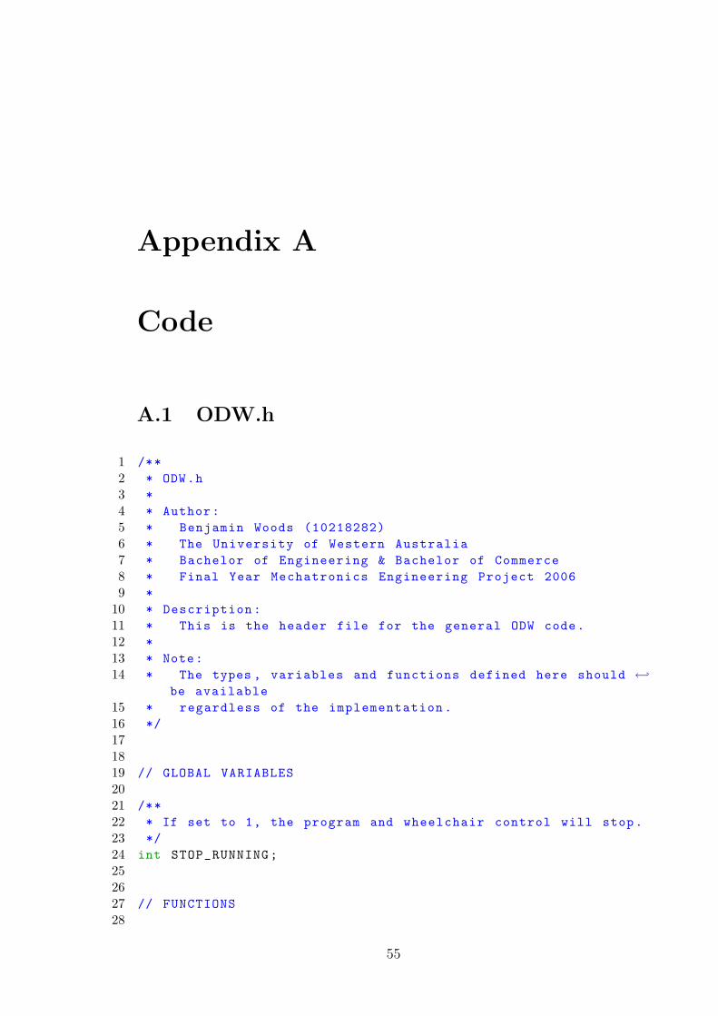
Appendix A
Code
A.1 ODW.h
1 /**2 * ODW.h3 *4 * Author:5 * Benjamin Woods (10218282)6 * The University of Western Australia7 * Bachelor of Engineering & Bachelor of Commerce8 * Final Year Mechatronics Engineering Project 20069 *
10 * Description:11 * This is the header file for the general ODW code.12 *13 * Note:14 * The types , variables and functions defined here should ←
be available15 * regardless of the implementation.16 */171819 // GLOBAL VARIABLES2021 /**22 * If set to 1, the program and wheelchair control will stop.23 */24 int STOP_RUNNING;252627 // FUNCTIONS28
55
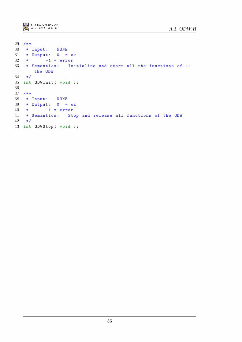
A.1. ODW.H
29 /**30 * Input: NONE31 * Output: 0 = ok32 * -1 = error33 * Semantics: Initialise and start all the functions of ←
the ODW34 */35 int ODWInit( void );3637 /**38 * Input: NONE39 * Output: 0 = ok40 * -1 = error41 * Semantics: Stop and release all functions of the ODW42 */43 int ODWStop( void );
56
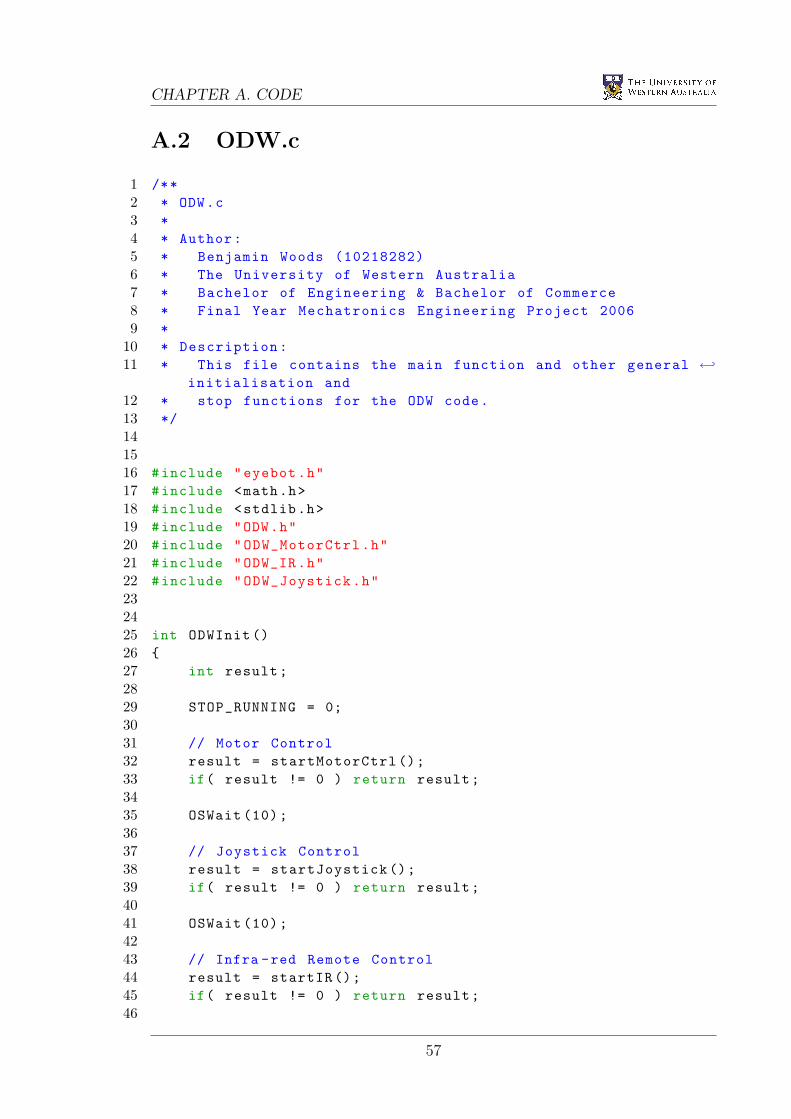
CHAPTER A. CODE
A.2 ODW.c
1 /**2 * ODW.c3 *4 * Author:5 * Benjamin Woods (10218282)6 * The University of Western Australia7 * Bachelor of Engineering & Bachelor of Commerce8 * Final Year Mechatronics Engineering Project 20069 *
10 * Description:11 * This file contains the main function and other general ←
initialisation and12 * stop functions for the ODW code.13 */141516 #include "eyebot.h"17 #include <math.h>18 #include <stdlib.h>19 #include "ODW.h"20 #include "ODW_MotorCtrl.h"21 #include "ODW_IR.h"22 #include "ODW_Joystick.h"232425 int ODWInit ()26 27 int result;2829 STOP_RUNNING = 0;3031 // Motor Control32 result = startMotorCtrl ();33 if( result != 0 ) return result;3435 OSWait (10);3637 // Joystick Control38 result = startJoystick ();39 if( result != 0 ) return result;4041 OSWait (10);4243 // Infra -red Remote Control44 result = startIR ();45 if( result != 0 ) return result;46
57
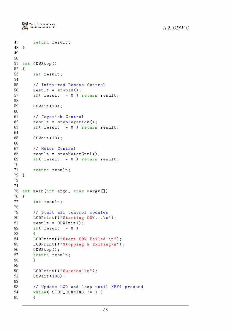
A.2. ODW.C
47 return result;48 495051 int ODWStop ()52 53 int result;5455 // Infra -red Remote Control56 result = stopIR ();57 if( result != 0 ) return result;5859 OSWait (10);6061 // Joystick Control62 result = stopJoystick ();63 if( result != 0 ) return result;6465 OSWait (10);6667 // Motor Control68 result = stopMotorCtrl ();69 if( result != 0 ) return result;7071 return result;72 737475 int main(int argc , char *argv [])76 77 int result;7879 // Start all control modules80 LCDPrintf("Starting ODW ...\n");81 result = ODWInit ();82 if( result != 0 )83 84 LCDPrintf("Start ODW Failed !\n");85 LCDPrintf("Stopping & Exiting\n");86 ODWStop ();87 return result;88 8990 LCDPrintf("Success !\n");91 OSWait (100);9293 // Update LCD and loop until KEY4 pressed94 while( STOP_RUNNING != 1 )95
58
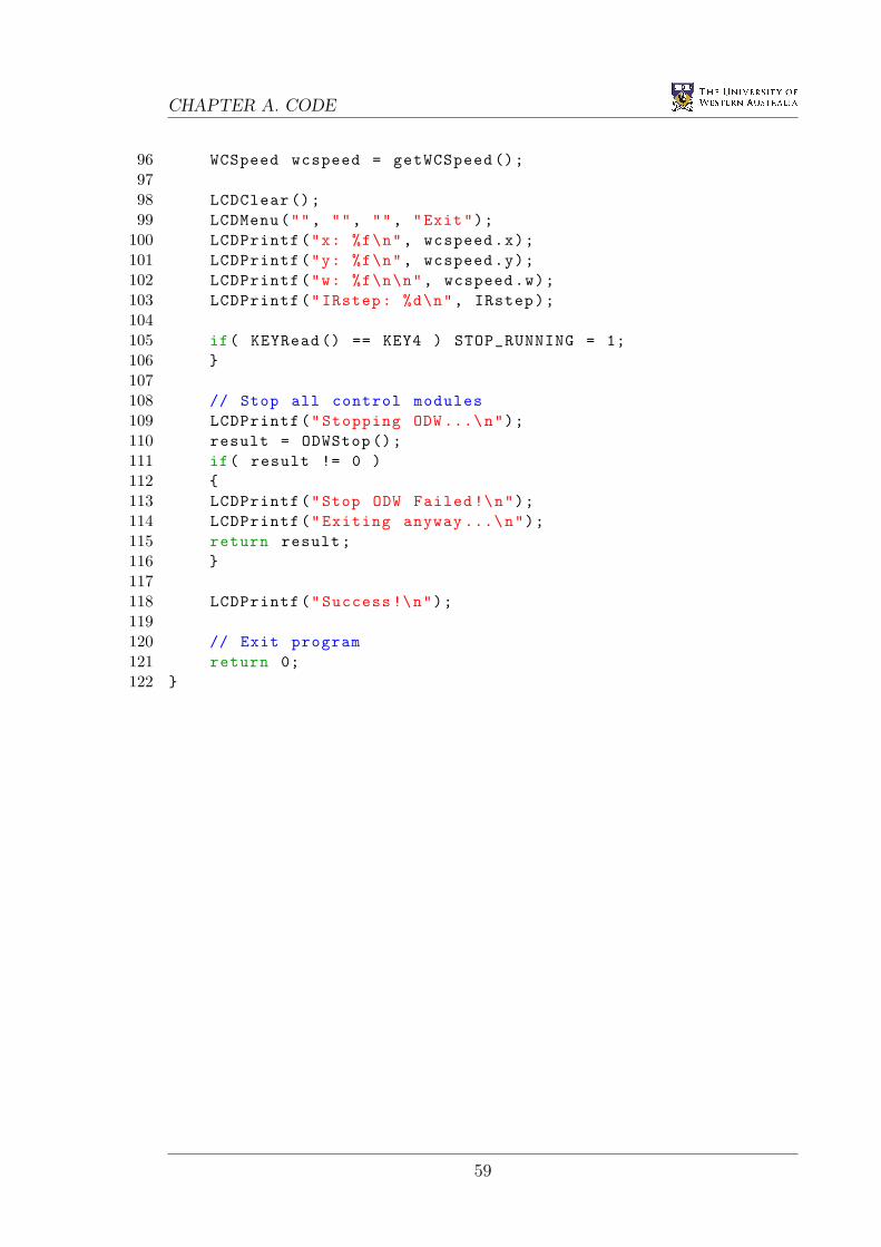
CHAPTER A. CODE
96 WCSpeed wcspeed = getWCSpeed ();9798 LCDClear ();99 LCDMenu("", "", "", "Exit");
100 LCDPrintf("x: %f\n", wcspeed.x);101 LCDPrintf("y: %f\n", wcspeed.y);102 LCDPrintf("w: %f\n\n", wcspeed.w);103 LCDPrintf("IRstep: %d\n", IRstep);104105 if( KEYRead () == KEY4 ) STOP_RUNNING = 1;106 107108 // Stop all control modules109 LCDPrintf("Stopping ODW ...\n");110 result = ODWStop ();111 if( result != 0 )112 113 LCDPrintf("Stop ODW Failed !\n");114 LCDPrintf("Exiting anyway ...\n");115 return result;116 117118 LCDPrintf("Success !\n");119120 // Exit program121 return 0;122
59
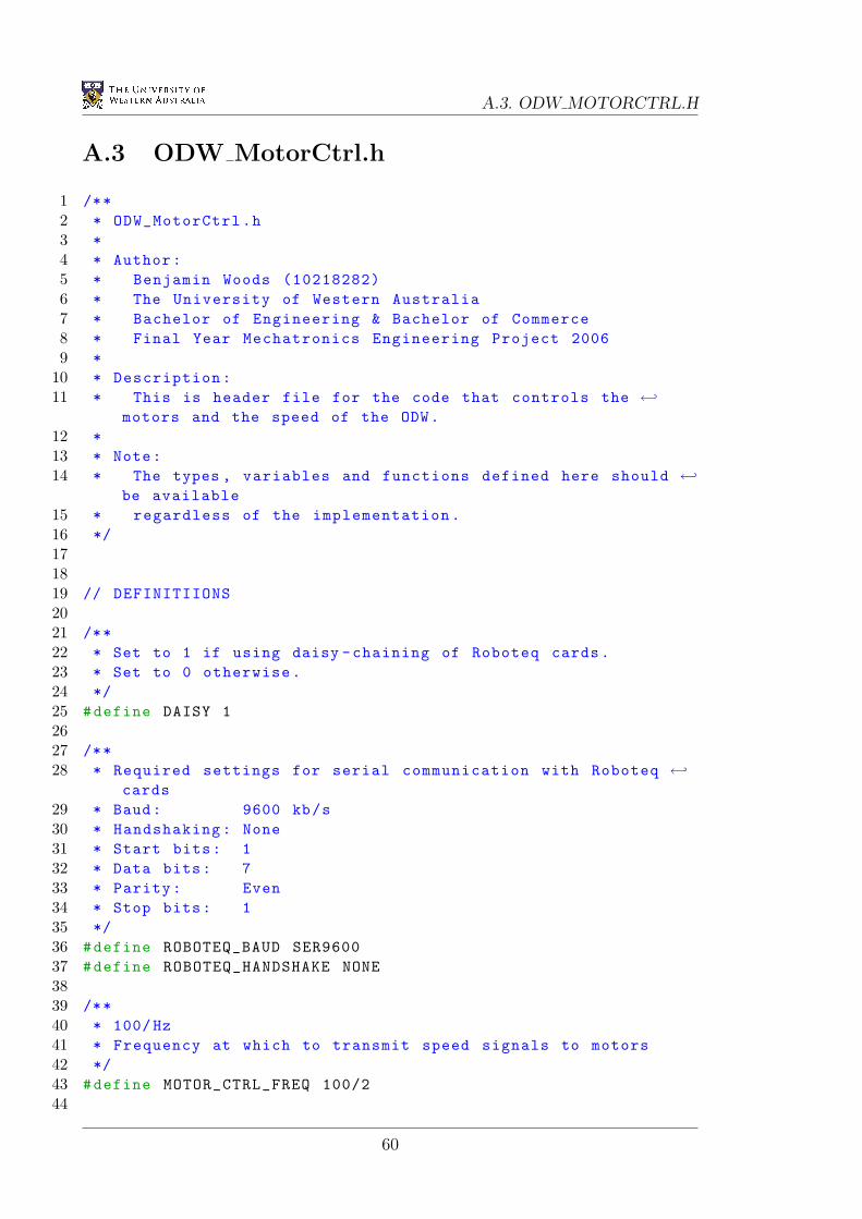
A.3. ODW MOTORCTRL.H
A.3 ODW MotorCtrl.h
1 /**2 * ODW_MotorCtrl.h3 *4 * Author:5 * Benjamin Woods (10218282)6 * The University of Western Australia7 * Bachelor of Engineering & Bachelor of Commerce8 * Final Year Mechatronics Engineering Project 20069 *
10 * Description:11 * This is header file for the code that controls the ←
motors and the speed of the ODW.12 *13 * Note:14 * The types , variables and functions defined here should ←
be available15 * regardless of the implementation.16 */171819 // DEFINITIIONS2021 /**22 * Set to 1 if using daisy -chaining of Roboteq cards.23 * Set to 0 otherwise.24 */25 #define DAISY 12627 /**28 * Required settings for serial communication with Roboteq ←
cards29 * Baud: 9600 kb/s30 * Handshaking: None31 * Start bits: 132 * Data bits: 733 * Parity: Even34 * Stop bits: 135 */36 #define ROBOTEQ_BAUD SER960037 #define ROBOTEQ_HANDSHAKE NONE3839 /**40 * 100/Hz41 * Frequency at which to transmit speed signals to motors42 */43 #define MOTOR_CTRL_FREQ 100/244
60
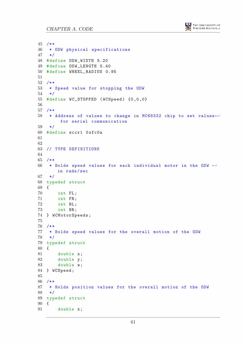
CHAPTER A. CODE
45 /**46 * ODW physical specifications47 */48 #define ODW_WIDTH 5.2049 #define ODW_LENGTH 5.4050 #define WHEEL_RADIUS 0.955152 /**53 * Speed value for stopping the ODW54 */55 #define WC_STOPPED (WCSpeed) 0,0,05657 /**58 * Address of values to change in MC68332 chip to set values←
for serial communication59 */60 #define sccr1 0xfc0a616263 // TYPE DEFINITIONS6465 /**66 * Holds speed values for each individual motor in the ODW ←
in rads/sec67 */68 typedef struct69 70 int FL;71 int FR;72 int BL;73 int BR;74 WCMotorSpeeds;7576 /**77 * Holds speed values for the overall motion of the ODW78 */79 typedef struct80 81 double x;82 double y;83 double w;84 WCSpeed;8586 /**87 * Holds position values for the overall motion of the ODW88 */89 typedef struct90 91 double x;
61
A.3. ODW MOTORCTRL.H
92 double y;93 double phi;94 WCPosition;959697 // GLOBAL VARIABLES9899 /**
100 * The currently desired individual motor speeds.101 * Max value per motor = 127 = 0x7F102 */103 WCMotorSpeeds DESIRED_MOTOR_SPEEDS;104105 /**106 * The currently desired overall ODW speed.107 * Max value per axis = 100108 */109 WCSpeed DESIRED_WC_SPEED;110111 /**112 * The handle for the timer which continues to113 * send the currently desired motor speeds to the114 * motor controller cards.115 */116 TimerHandle MotorCtrlTimer;117118119 // FUNCTIONS120121 /**122 * Input: (wcmotorspeeds) The motor speeds to convert123 * Output: The corresponding overall speed of the ODW124 * Semantics: Convert individual motor speeds into the ←
overall WC speed125 */126 WCSpeed forwardKinematics( WCMotorSpeeds wcmotorspeeds );127128 /**129 * Input: (wcspeed) The overall speed of the ODW to convert130 * Output: The corresponding speeds of the individual motors131 * Semantics: Convert the overall WC speed into required ←
individual motor speeds132 */133 WCMotorSpeeds inverseKinematics( WCSpeed wcspeed );134135 /**136 * Input: NONE137 * Output: 0 = ok138 * -1 = error
62
CHAPTER A. CODE
139 * Semantics: Set up and start the control of the motors140 */141 int startMotorCtrl( void );142143 /**144 * Input: NONE145 * Output: 0 = ok146 * -1 = error147 * Semantics: Stop the control of the motors and release ←
the serial ports148 */149 int stopMotorCtrl( void );150151 /**152 * Input: NONE153 * Output: NONE154 * Semantics: Control the motors using the global ←
parameters155 */156 void MotorCtrl( void );157158 /**159 * Input: (wcspeed) The speed values to set for the ODW160 * Output: 0 = ok161 * -1 = error162 * Semantics: Set the speed of the overall ODW (rather ←
than each motor independently)163 */164 int setWCSpeed( WCSpeed wcspeed );165166 /**167 * Input: NONE168 * Output: The currently desired speed for the ODW169 * Semantics: Get the current desired speed of the overall←
ODW (rather than each individual motor)170 */171 WCSpeed getWCSpeed( void );172173 /**174 * Input: (wcmotorspeeds) The speed of each motor to set175 * Output: 0 = ok176 * -1 = error177 * Semantics: Set the speed of each motor independently ←
(rather than the overall ODW)178 */179 int setWCMotorSpeeds( WCMotorSpeeds wcmotorspeeds );180181 /**182 * Input: NONE
63
A.3. ODW MOTORCTRL.H
183 * Output: The currently desired motor speeds184 * Semantics: Get the current desired speed of each ←
individual motor (rather than the overall ODW)185 */186 WCMotorSpeeds getWCMotorSpeeds( void );
64
CHAPTER A. CODE
A.4 ODW MotorCtrl.c
1 /**2 * ODW_MotorCtrl.c3 *4 * Author:5 * Benjamin Woods (10218282)6 * The University of Western Australia7 * Bachelor of Engineering & Bachelor of Commerce8 * Final Year Mechatronics Engineering Project 20069 *
10 * Description:11 * This is code to control the motors and the speed of the←
ODW.12 * This implementation uses the Roboteq AX1500 cards ←
installed.13 */141516 #include "eyebot.h"17 #include "ODW_MotorCtrl.h"18 #include <math.h>19 #include <stdio.h>20 #include <stdlib.h>212223 WCSpeed forwardKinematics( WCMotorSpeeds wcmotorspeeds )24 25 WCSpeed wcspeed;2627 // Find ODW speeds by converting motor speeds28 wcspeed.x = ( wcmotorspeeds.FL + wcmotorspeeds.FR + ←
wcmotorspeeds.BL + wcmotorspeeds.BR ) * 100.0 / ←(127.0*4);
29 wcspeed.y = ( -wcmotorspeeds.FL + wcmotorspeeds.FR + ←wcmotorspeeds.BL - wcmotorspeeds.BR ) * 100.0 / ←(127.0*4);
30 wcspeed.w = ( -wcmotorspeeds.FL + wcmotorspeeds.FR - ←wcmotorspeeds.BL + wcmotorspeeds.BR ) * 100.0 / ←(127.0*4);
3132 return wcspeed;33 343536 WCMotorSpeeds inverseKinematics( WCSpeed wcspeed )37 38 WCMotorSpeeds wcmotorspeeds;39
65
A.4. ODW MOTORCTRL.C
40 // Find motor speeds by converting ODW speed components41 wcmotorspeeds.FL = round( ( wcspeed.x - wcspeed.y - ←
wcspeed.w ) * 127.0/100.0 );42 wcmotorspeeds.FR = round( ( wcspeed.x + wcspeed.y + ←
wcspeed.w ) * 127.0/100.0 );43 wcmotorspeeds.BL = round( ( wcspeed.x + wcspeed.y - ←
wcspeed.w ) * 127.0/100.0 );44 wcmotorspeeds.BR = round( ( wcspeed.x - wcspeed.y + ←
wcspeed.w ) * 127.0/100.0 );4546 // If any of the motor speeds are outside [-127, 127] ←
then scale all speeds down47 // the fastest motor is spinning at 100% speed (either ←
-127 or 127).48 double scaling_factor = 1;49 if( (wcmotorspeeds.FL > 127) && ( ←
127.0/ wcmotorspeeds.FL < scaling_factor) ) ←scaling_factor = 127.0 / wcmotorspeeds.FL;
50 if( (wcmotorspeeds.FR > 127) && ( ←127.0/ wcmotorspeeds.FR < scaling_factor) ) ←scaling_factor = 127.0 / wcmotorspeeds.FR;
51 if( (wcmotorspeeds.BL > 127) && ( ←127.0/ wcmotorspeeds.BL < scaling_factor) ) ←scaling_factor = 127.0 / wcmotorspeeds.BL;
52 if( (wcmotorspeeds.BR > 127) && ( ←127.0/ wcmotorspeeds.BR < scaling_factor) ) ←scaling_factor = 127.0 / wcmotorspeeds.BR;
53 if( (wcmotorspeeds.FL < -127) && ←( -127.0/ wcmotorspeeds.FL < scaling_factor) ) ←scaling_factor = -127.0 / wcmotorspeeds.FL;
54 if( (wcmotorspeeds.FR < -127) && ←( -127.0/ wcmotorspeeds.FR < scaling_factor) ) ←scaling_factor = -127.0 / wcmotorspeeds.FR;
55 if( (wcmotorspeeds.BL < -127) && ←( -127.0/ wcmotorspeeds.BL < scaling_factor) ) ←scaling_factor = -127.0 / wcmotorspeeds.BL;
56 if( (wcmotorspeeds.BR < -127) && ←( -127.0/ wcmotorspeeds.BR < scaling_factor) ) ←scaling_factor = -127.0 / wcmotorspeeds.BR;
5758 wcmotorspeeds.FL = round( scaling_factor * ←
wcmotorspeeds.FL );59 wcmotorspeeds.FR = round( scaling_factor * ←
wcmotorspeeds.FR );60 wcmotorspeeds.BL = round( scaling_factor * ←
wcmotorspeeds.BL );61 wcmotorspeeds.BR = round( scaling_factor * ←
wcmotorspeeds.BR );62
66
CHAPTER A. CODE
63 return wcmotorspeeds;64 656667 int startMotorCtrl ()68 69 // Initialise the second serial port for transmission to←
Roboteq cards70 LCDPrintf("Init SERIAL2 ...\n");71 int result = OSInitRS232( ROBOTEQ_BAUD , ←
ROBOTEQ_HANDSHAKE , SERIAL2 );72 // The next line sets even parity for serial interface 273 (*((( volatile BYTE*) Ser1Base)+3)) = 0x1a;7475 // If not using daisy chaining , also initialise the ←
first serial port76 if( !DAISY ) 77 LCDPrintf("Init SERIAL1 ...\n");78 result = result && OSInitRS232( ROBOTEQ_BAUD , ←
ROBOTEQ_HANDSHAKE , SERIAL1 );79 // The next line sets even parity for serial ←
interface 180 (*(( volatile unsigned short *) sccr1)) = 0x042c;81 8283 setWCSpeed( WC_STOPPED );8485 MotorCtrlTimer = OSAttachTimer( MOTOR_CTRL_FREQ , ←
MotorCtrl );8687 return (result);88 899091 int stopMotorCtrl ()92 93 // Stop continuous transmission of speed signals94 int result = !OSDetachTimer( MotorCtrlTimer );9596 // Send one last transmission of zero values97 setWCSpeed( WC_STOPPED );98 MotorCtrl ();99
100 return result;101 102103104 void MotorCtrl ()105
67
A.4. ODW MOTORCTRL.C
106 // Grab a snapshot of the currently desired motor speeds107 int FL = DESIRED_MOTOR_SPEEDS.FL;108 int FR = DESIRED_MOTOR_SPEEDS.FR*-1; // FR motor spins ←
backwards with +ve signal109 int BL = DESIRED_MOTOR_SPEEDS.BL;110 int BR = DESIRED_MOTOR_SPEEDS.BR*-1; // BR motor spins ←
backwards with +ve signal111112 // Limit speeds to allowed values between -127 and 127113 if( FL > 127 ) FL = 127;114 if( FR > 127 ) FR = 127;115 if( BL > 127 ) BL = 127;116 if( BR > 127 ) BR = 127;117 if( FL < -127 ) FL = -127;118 if( FR < -127 ) FR = -127;119 if( BL < -127 ) BL = -127;120 if( BR < -127 ) BR = -127;121122 // Convert integer values into hexidecimal characters123 char sFL[3], sFR[3], sBL[3], sBR [3];124 snprintf( sFL , 3, "%X", abs(FL) );125 snprintf( sFR , 3, "%X", abs(FR) );126 snprintf( sBL , 3, "%X", abs(BL) );127 snprintf( sBR , 3, "%X", abs(BR) );128129 // Ensure all character arrays contain exactly 2 ←
characters130 // (Pad the first character with a 0 if only 1 character←
is used)131 if( FL < 16 && FL > -16 )132 133 sFL[1] = sFL [0];134 sFL[0] = ’0’;135 136 if( FR < 16 && FR > -16 )137 138 sFR[1] = sFR [0];139 sFR[0] = ’0’;140 141 if( BL < 16 && BL > -16 )142 143 sBL[1] = sBL [0];144 sBL[0] = ’0’;145 146 if( BR < 16 && BR > -16 )147 148 sBR[1] = sBR [0];149 sBR[0] = ’0’;150
68
CHAPTER A. CODE
151152 // Transmit commands for the front left motor153 OSSendCharRS232( ’!’, SERIAL2 );154 if ( FL < 0 ) OSSendCharRS232( ’a’, SERIAL2 );155 else OSSendCharRS232( ’A’, SERIAL2 );156 OSSendCharRS232( sFL[0], SERIAL2 );157 OSSendCharRS232( sFL[1], SERIAL2 );158 OSSendCharRS232( ’\r’, SERIAL2 );159160 // Transmit commands for the front right motor161 OSSendCharRS232( ’!’, SERIAL2 );162 if ( FR < 0 ) OSSendCharRS232( ’b’, SERIAL2 );163 else OSSendCharRS232( ’B’, SERIAL2 );164 OSSendCharRS232( sFR[0], SERIAL2 );165 OSSendCharRS232( sFR[1], SERIAL2 );166 OSSendCharRS232( ’\r’, SERIAL2 );167168 // Transmit commands for the back right motor169 OSSendCharRS232( ’!’+DAISY , SERIAL1+DAISY );170 if ( BR < 0 ) OSSendCharRS232( ’a’, SERIAL1+DAISY );171 else OSSendCharRS232( ’A’, SERIAL1+DAISY );172 OSSendCharRS232( sBR[0], SERIAL1+DAISY );173 OSSendCharRS232( sBR[1], SERIAL1+DAISY );174 OSSendCharRS232( ’\r’, SERIAL1+DAISY );175176 // Transmit commands for the back left motor177 OSSendCharRS232( ’!’+DAISY , SERIAL1+DAISY );178 if ( BL < 0 ) OSSendCharRS232( ’b’, SERIAL1+DAISY );179 else OSSendCharRS232( ’B’, SERIAL1+DAISY );180 OSSendCharRS232( sBL[0], SERIAL1+DAISY );181 OSSendCharRS232( sBL[1], SERIAL1+DAISY );182 OSSendCharRS232( ’\r’, SERIAL1+DAISY );183 184185186 int setWCSpeed( WCSpeed wcspeed )187 188 // Convert desired ODW speed into required wheel speeds189 WCMotorSpeeds wcmotorspeeds = inverseKinematics( wcspeed←
);190191 return setWCMotorSpeeds( wcmotorspeeds );192 193194195 WCSpeed getWCSpeed ()196 197 WCMotorSpeeds wcmotorspeeds = getWCMotorSpeeds ();198
69
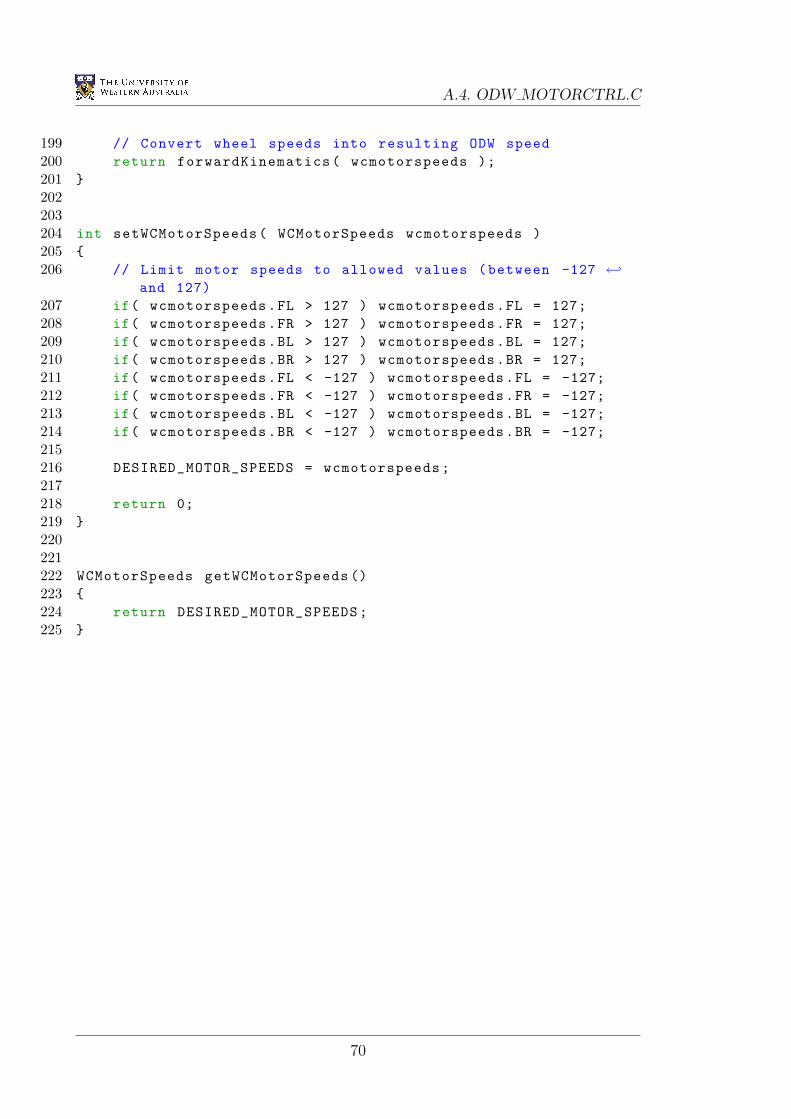
A.4. ODW MOTORCTRL.C
199 // Convert wheel speeds into resulting ODW speed200 return forwardKinematics( wcmotorspeeds );201 202203204 int setWCMotorSpeeds( WCMotorSpeeds wcmotorspeeds )205 206 // Limit motor speeds to allowed values (between -127 ←
and 127)207 if( wcmotorspeeds.FL > 127 ) wcmotorspeeds.FL = 127;208 if( wcmotorspeeds.FR > 127 ) wcmotorspeeds.FR = 127;209 if( wcmotorspeeds.BL > 127 ) wcmotorspeeds.BL = 127;210 if( wcmotorspeeds.BR > 127 ) wcmotorspeeds.BR = 127;211 if( wcmotorspeeds.FL < -127 ) wcmotorspeeds.FL = -127;212 if( wcmotorspeeds.FR < -127 ) wcmotorspeeds.FR = -127;213 if( wcmotorspeeds.BL < -127 ) wcmotorspeeds.BL = -127;214 if( wcmotorspeeds.BR < -127 ) wcmotorspeeds.BR = -127;215216 DESIRED_MOTOR_SPEEDS = wcmotorspeeds;217218 return 0;219 220221222 WCMotorSpeeds getWCMotorSpeeds ()223 224 return DESIRED_MOTOR_SPEEDS;225
70
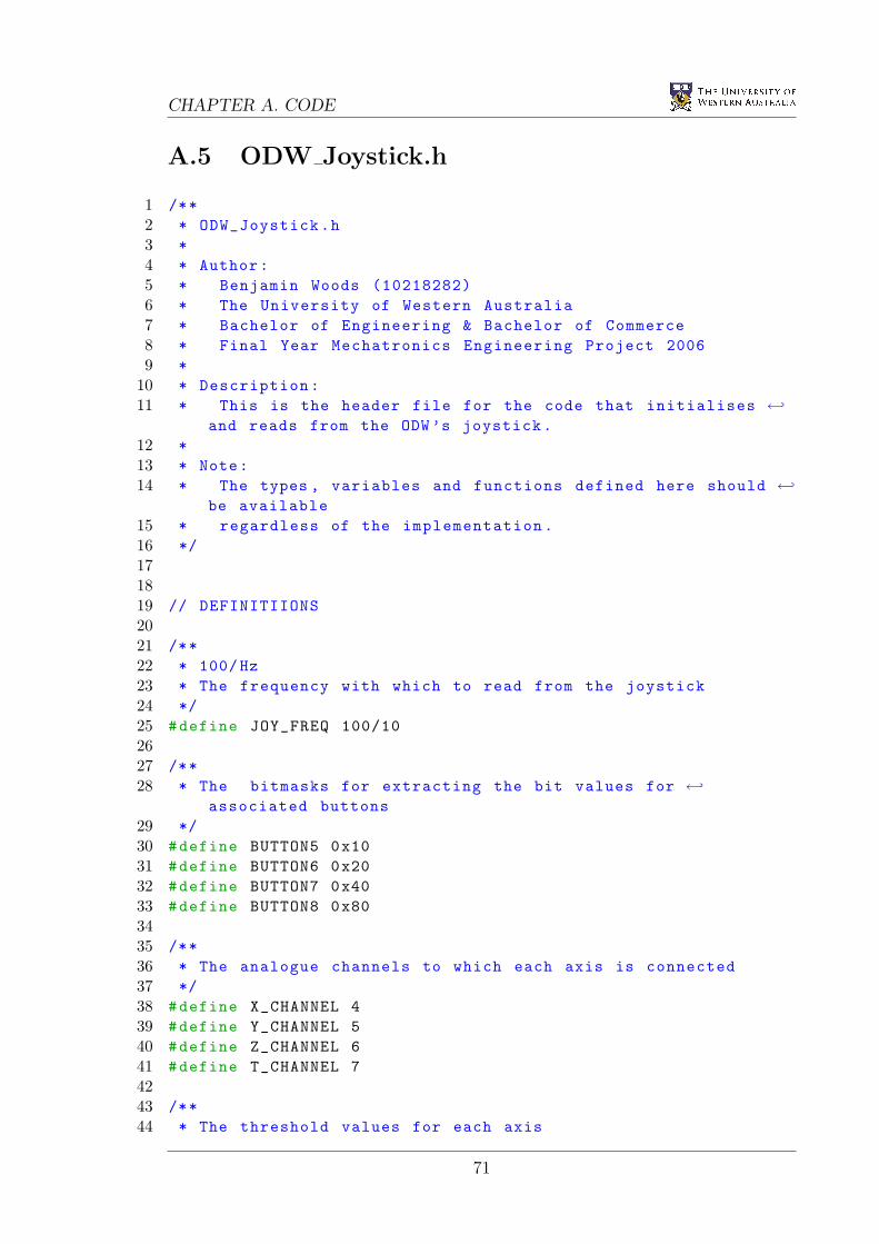
CHAPTER A. CODE
A.5 ODW Joystick.h
1 /**2 * ODW_Joystick.h3 *4 * Author:5 * Benjamin Woods (10218282)6 * The University of Western Australia7 * Bachelor of Engineering & Bachelor of Commerce8 * Final Year Mechatronics Engineering Project 20069 *
10 * Description:11 * This is the header file for the code that initialises ←
and reads from the ODW’s joystick.12 *13 * Note:14 * The types , variables and functions defined here should ←
be available15 * regardless of the implementation.16 */171819 // DEFINITIIONS2021 /**22 * 100/Hz23 * The frequency with which to read from the joystick24 */25 #define JOY_FREQ 100/102627 /**28 * The bitmasks for extracting the bit values for ←
associated buttons29 */30 #define BUTTON5 0x1031 #define BUTTON6 0x2032 #define BUTTON7 0x4033 #define BUTTON8 0x803435 /**36 * The analogue channels to which each axis is connected37 */38 #define X_CHANNEL 439 #define Y_CHANNEL 540 #define Z_CHANNEL 641 #define T_CHANNEL 74243 /**44 * The threshold values for each axis
71
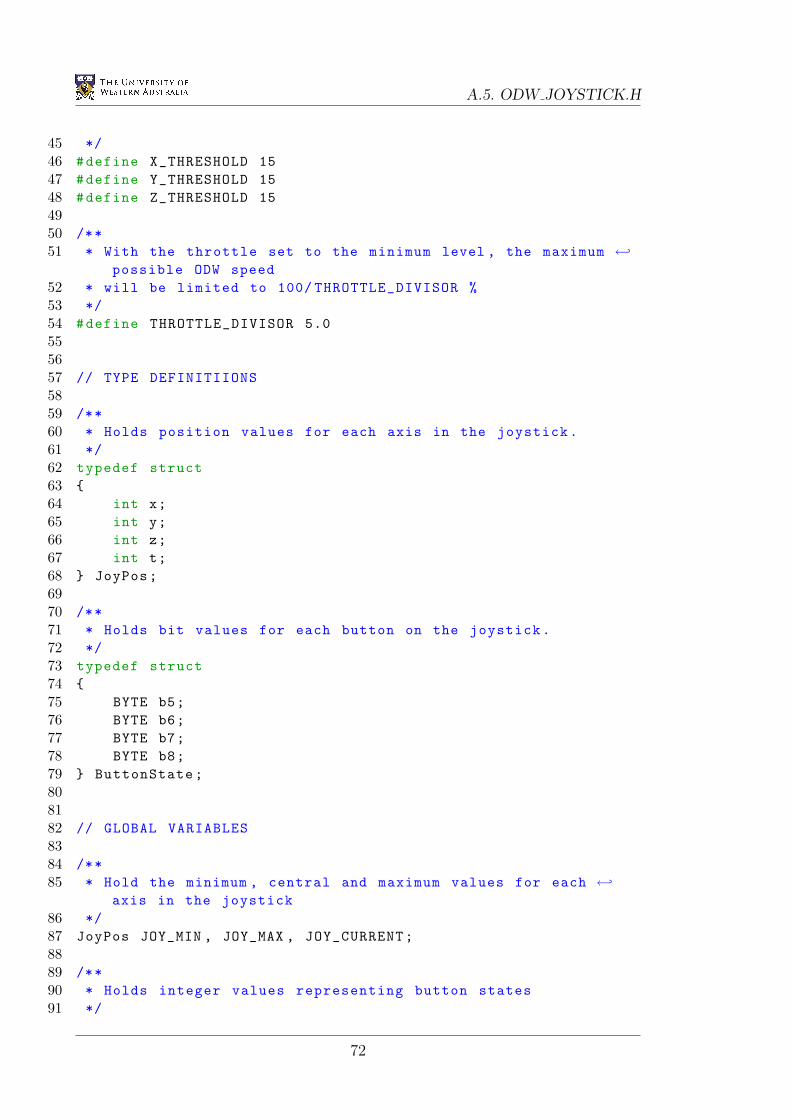
A.5. ODW JOYSTICK.H
45 */46 #define X_THRESHOLD 1547 #define Y_THRESHOLD 1548 #define Z_THRESHOLD 154950 /**51 * With the throttle set to the minimum level , the maximum ←
possible ODW speed52 * will be limited to 100/ THROTTLE_DIVISOR %53 */54 #define THROTTLE_DIVISOR 5.0555657 // TYPE DEFINITIIONS5859 /**60 * Holds position values for each axis in the joystick.61 */62 typedef struct63 64 int x;65 int y;66 int z;67 int t;68 JoyPos;6970 /**71 * Holds bit values for each button on the joystick.72 */73 typedef struct74 75 BYTE b5;76 BYTE b6;77 BYTE b7;78 BYTE b8;79 ButtonState;808182 // GLOBAL VARIABLES8384 /**85 * Hold the minimum , central and maximum values for each ←
axis in the joystick86 */87 JoyPos JOY_MIN , JOY_MAX , JOY_CURRENT;8889 /**90 * Holds integer values representing button states91 */
72
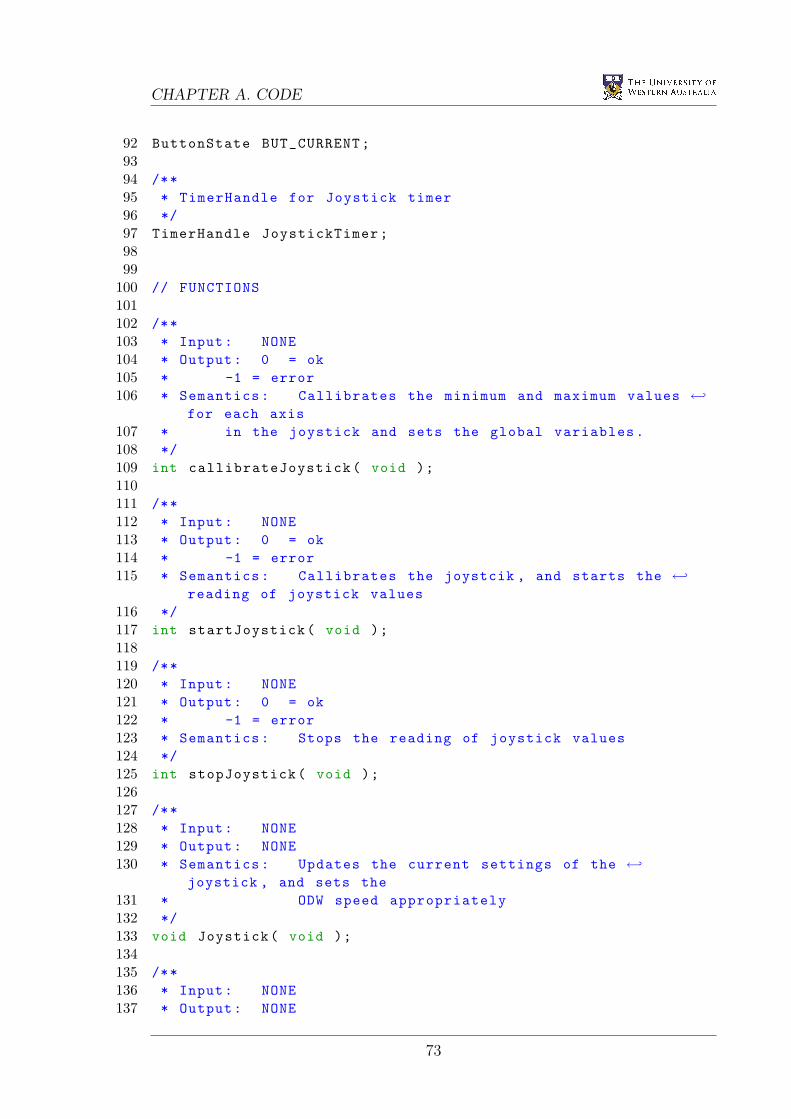
CHAPTER A. CODE
92 ButtonState BUT_CURRENT;9394 /**95 * TimerHandle for Joystick timer96 */97 TimerHandle JoystickTimer;9899
100 // FUNCTIONS101102 /**103 * Input: NONE104 * Output: 0 = ok105 * -1 = error106 * Semantics: Callibrates the minimum and maximum values ←
for each axis107 * in the joystick and sets the global variables.108 */109 int callibrateJoystick( void );110111 /**112 * Input: NONE113 * Output: 0 = ok114 * -1 = error115 * Semantics: Callibrates the joystcik , and starts the ←
reading of joystick values116 */117 int startJoystick( void );118119 /**120 * Input: NONE121 * Output: 0 = ok122 * -1 = error123 * Semantics: Stops the reading of joystick values124 */125 int stopJoystick( void );126127 /**128 * Input: NONE129 * Output: NONE130 * Semantics: Updates the current settings of the ←
joystick , and sets the131 * ODW speed appropriately132 */133 void Joystick( void );134135 /**136 * Input: NONE137 * Output: NONE
73
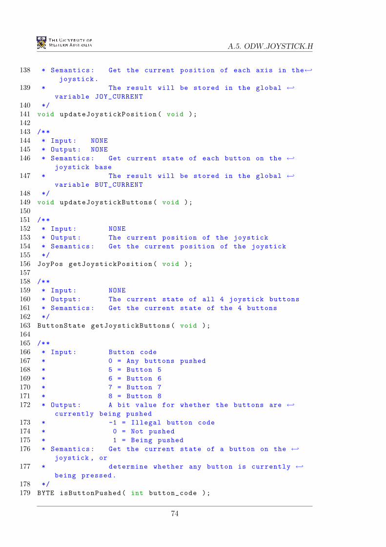
A.5. ODW JOYSTICK.H
138 * Semantics: Get the current position of each axis in the←joystick.
139 * The result will be stored in the global ←variable JOY_CURRENT
140 */141 void updateJoystickPosition( void );142143 /**144 * Input: NONE145 * Output: NONE146 * Semantics: Get current state of each button on the ←
joystick base147 * The result will be stored in the global ←
variable BUT_CURRENT148 */149 void updateJoystickButtons( void );150151 /**152 * Input: NONE153 * Output: The current position of the joystick154 * Semantics: Get the current position of the joystick155 */156 JoyPos getJoystickPosition( void );157158 /**159 * Input: NONE160 * Output: The current state of all 4 joystick buttons161 * Semantics: Get the current state of the 4 buttons162 */163 ButtonState getJoystickButtons( void );164165 /**166 * Input: Button code167 * 0 = Any buttons pushed168 * 5 = Button 5169 * 6 = Button 6170 * 7 = Button 7171 * 8 = Button 8172 * Output: A bit value for whether the buttons are ←
currently being pushed173 * -1 = Illegal button code174 * 0 = Not pushed175 * 1 = Being pushed176 * Semantics: Get the current state of a button on the ←
joystick , or177 * determine whether any button is currently ←
being pressed.178 */179 BYTE isButtonPushed( int button_code );
74
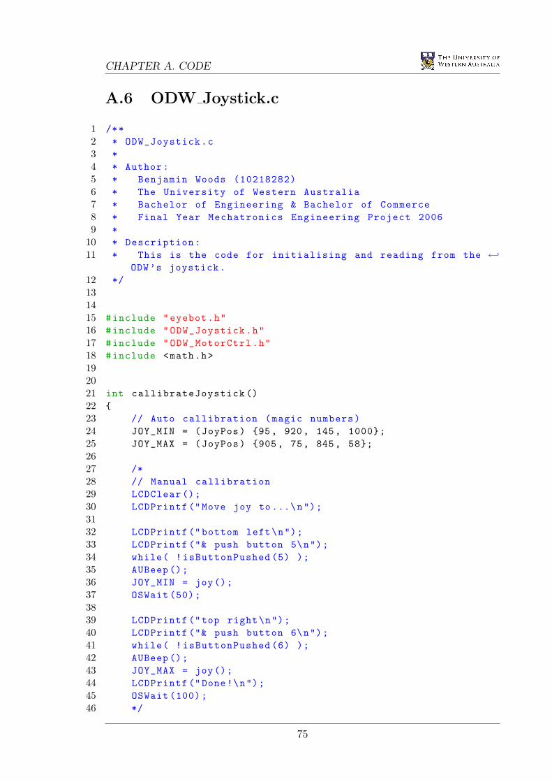
CHAPTER A. CODE
A.6 ODW Joystick.c
1 /**2 * ODW_Joystick.c3 *4 * Author:5 * Benjamin Woods (10218282)6 * The University of Western Australia7 * Bachelor of Engineering & Bachelor of Commerce8 * Final Year Mechatronics Engineering Project 20069 *
10 * Description:11 * This is the code for initialising and reading from the ←
ODW’s joystick.12 */131415 #include "eyebot.h"16 #include "ODW_Joystick.h"17 #include "ODW_MotorCtrl.h"18 #include <math.h>192021 int callibrateJoystick ()22 23 // Auto callibration (magic numbers)24 JOY_MIN = (JoyPos) 95, 920, 145, 1000;25 JOY_MAX = (JoyPos) 905, 75, 845, 58;2627 /*28 // Manual callibration29 LCDClear ();30 LCDPrintf ("Move joy to...\n");3132 LCDPrintf (" bottom left\n");33 LCDPrintf ("& push button 5\n");34 while( !isButtonPushed (5) );35 AUBeep ();36 JOY_MIN = joy();37 OSWait (50);3839 LCDPrintf ("top right\n");40 LCDPrintf ("& push button 6\n");41 while( !isButtonPushed (6) );42 AUBeep ();43 JOY_MAX = joy();44 LCDPrintf ("Done!\n");45 OSWait (100);46 */
75
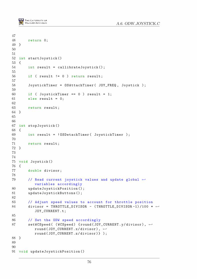
A.6. ODW JOYSTICK.C
4748 return 0;49 505152 int startJoystick ()53 54 int result = callibrateJoystick ();5556 if ( result != 0 ) return result;5758 JoystickTimer = OSAttachTimer( JOY_FREQ , Joystick );5960 if ( JoystickTimer == 0 ) result = 1;61 else result = 0;6263 return result;64 656667 int stopJoystick ()68 69 int result = !OSDetachTimer( JoystickTimer );7071 return result;72 737475 void Joystick ()76 77 double divisor;7879 // Read current joystick values and update global ←
variables accordingly80 updateJoystickPosition ();81 updateJoystickButtons ();8283 // Adjust speed values to account for throttle position84 divisor = THROTTLE_DIVISOR - (THROTTLE_DIVISOR -1) /100 * ←
JOY_CURRENT.t;8586 // Set the ODW speed accordingly87 setWCSpeed( (WCSpeed) round(JOY_CURRENT.y/divisor), ←
round(JOY_CURRENT.x/divisor), ←round(JOY_CURRENT.z/divisor) );
88 899091 void updateJoystickPosition ()
76
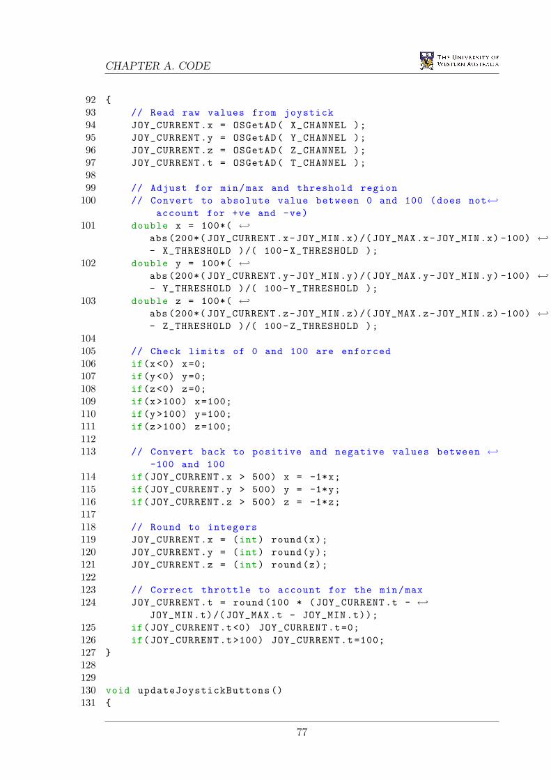
CHAPTER A. CODE
92 93 // Read raw values from joystick94 JOY_CURRENT.x = OSGetAD( X_CHANNEL );95 JOY_CURRENT.y = OSGetAD( Y_CHANNEL );96 JOY_CURRENT.z = OSGetAD( Z_CHANNEL );97 JOY_CURRENT.t = OSGetAD( T_CHANNEL );9899 // Adjust for min/max and threshold region
100 // Convert to absolute value between 0 and 100 (does not←account for +ve and -ve)
101 double x = 100*( ←abs (200*( JOY_CURRENT.x-JOY_MIN.x)/( JOY_MAX.x-JOY_MIN.x) -100) ←- X_THRESHOLD )/( 100- X_THRESHOLD );
102 double y = 100*( ←abs (200*( JOY_CURRENT.y-JOY_MIN.y)/( JOY_MAX.y-JOY_MIN.y) -100) ←- Y_THRESHOLD )/( 100- Y_THRESHOLD );
103 double z = 100*( ←abs (200*( JOY_CURRENT.z-JOY_MIN.z)/( JOY_MAX.z-JOY_MIN.z) -100) ←- Z_THRESHOLD )/( 100- Z_THRESHOLD );
104105 // Check limits of 0 and 100 are enforced106 if(x<0) x=0;107 if(y<0) y=0;108 if(z<0) z=0;109 if(x >100) x=100;110 if(y >100) y=100;111 if(z >100) z=100;112113 // Convert back to positive and negative values between ←
-100 and 100114 if(JOY_CURRENT.x > 500) x = -1*x;115 if(JOY_CURRENT.y > 500) y = -1*y;116 if(JOY_CURRENT.z > 500) z = -1*z;117118 // Round to integers119 JOY_CURRENT.x = (int) round(x);120 JOY_CURRENT.y = (int) round(y);121 JOY_CURRENT.z = (int) round(z);122123 // Correct throttle to account for the min/max124 JOY_CURRENT.t = round (100 * (JOY_CURRENT.t - ←
JOY_MIN.t)/( JOY_MAX.t - JOY_MIN.t));125 if(JOY_CURRENT.t<0) JOY_CURRENT.t=0;126 if(JOY_CURRENT.t>100) JOY_CURRENT.t=100;127 128129130 void updateJoystickButtons ()131
77
A.6. ODW JOYSTICK.C
132 // Read raw values from joystick , and extract associated←bit
133 BUT_CURRENT.b5 = !(( OSReadInLatch( 0 ) & ←BUTTON5)/BUTTON5);
134 BUT_CURRENT.b6 = !(( OSReadInLatch( 0 ) & ←BUTTON6)/BUTTON6);
135 BUT_CURRENT.b7 = !(( OSReadInLatch( 0 ) & ←BUTTON7)/BUTTON7);
136 BUT_CURRENT.b8 = !(( OSReadInLatch( 0 ) & ←BUTTON8)/BUTTON8);
137 138139 JoyPos getJoystickPosition( void )140 141 JoyPos joypos;142143 joypos.x = JOY_CURRENT.x;144 joypos.y = JOY_CURRENT.y;145 joypos.z = JOY_CURRENT.z;146 joypos.t = JOY_CURRENT.t;147148 return joypos;149 150151 ButtonState getJoystickButtons( void )152 153 ButtonState bs;154155 bs.b5 = BUT_CURRENT.b5;156 bs.b6 = BUT_CURRENT.b6;157 bs.b7 = BUT_CURRENT.b7;158 bs.b8 = BUT_CURRENT.b8;159160 return bs;161 162163 BYTE isButtonPushed( int button_code )164 165 switch ( button_code ) 166 case 0:167 return ( BUT_CURRENT.b5 || BUT_CURRENT.b6 || ←
BUT_CURRENT.b7 || BUT_CURRENT.b8 );168 break;169 case 5:170 return BUT_CURRENT.b5;171 break;172 case 6:173 return BUT_CURRENT.b6;174 break;
78
CHAPTER A. CODE
175 case 7:176 return BUT_CURRENT.b7;177 break;178 case 8:179 return BUT_CURRENT.b8;180 break;181 182183 return -1;184
79
A.7. ODW IR.H
A.7 ODW IR.h
1 /**2 * ODW_IR.h3 *4 * Author:5 * Benjamin Woods (10218282)6 * The University of Western Australia7 * Bachelor of Engineering & Bachelor of Commerce8 * Final Year Mechatronics Engineering Project 20069 *
10 * Description:11 * This is header file for the code that allows control of←
the ODW via an12 * infra -red remote control.13 *14 * Note:15 * The types , variables and functions defined here should ←
be available16 * regardless of the implementation.17 */181920 /**21 * Key Code Meaning22 *23 * 0 No Key24 * RC_0 0 Key25 * RC_1 1 Key26 * RC_2 2 Key27 * RC_3 3 Key28 * RC_4 4 Key29 * RC_5 5 Key30 * RC_6 6 Key31 * RC_7 7 Key32 * RC_8 8 Key33 * RC_9 9 Key34 * RC_PLUS + Key35 * RC_MINUS - Key36 * RC_FF >> Key37 * RC_RW << Key38 * RC_STOP Stop Key39 * RC_PLAY Play Key40 * RC_STANDBY On/Off Key41 * RC_OK OK Key42 */434445
80
CHAPTER A. CODE
46 // DEFINITIIONS4748 /**49 * 100/Hz50 * The frequency with which to check for an IR key press51 */52 #define IR_FREQ 100/10535455 // GLOBAL VARIABLES5657 /**58 * Handle for the Infra Red Timer which checks for an59 * infra red key press with frequency determined by IR_FREQ.60 */61 TimerHandle IRTimer;6263 /**64 * The size of a step increase in speed.65 */66 int IRstep;676869 // FUNCTIONS7071 /**72 * Input: NONE73 * Output: 0 = ok74 * -1 = error75 * Semantics: Initialise and start the control by IR ←
remote control76 */77 int startIR( void );7879 /**80 * Input: NONE81 * Output: 0 = ok82 * -1 = error83 * Semantics: Check for and deal with a key press84 */85 void IRKey( void );8687 /**88 * Input: NONE89 * Output: 0 = ok90 * -1 = error91 * Semantics: Stop the control by IR remote control92 */93 int stopIR( void );
81
A.8. ODW IR.C
A.8 ODW IR.c
1 /**2 * ODW_IR.c3 *4 * Author:5 * Benjamin Woods (10218282)6 * The University of Western Australia7 * Bachelor of Engineering & Bachelor of Commerce8 * Final Year Mechatronics Engineering Project 20069 *
10 * Description:11 * This is code to allow control of the ODW via an ←
infra -red remote control.12 */131415 #include "eyebot.h"16 #include "ODW_IR.h"17 #include "ODW_MotorCtrl.h"18 #include "irtv.h"19 #include "IRnokia.h"202122 int startIR( void )23 24 // Initialise IR using appropriate settings25 int result = ←
IRTVInit(SPACE_CODE ,15,0,0x03ff ,SLOPPY_MODE ,1 ,10);2627 IRstep = 10;28 IRTimer = OSAttachTimer( IR_FREQ , IRKey );2930 return result;31 323334 int stopIR( void )35 36 int result = !OSDetachTimer( IRTimer );37 // Terminate IR38 IRTVTerm ();3940 return result;41 424344 void IRKey( void )45
82
CHAPTER A. CODE
46 int IRKey = IRTVRead ();47 int x, y, w;48 WCSpeed currentwcspeed = getWCSpeed ();4950 switch( IRKey )51 52 case 0:53 // No key pressed54 break;5556 case RC_0:57 // 0 key pressed: STOP!58 setWCSpeed( WC_STOPPED );59 break;6061 case RC_1:62 // 1 key pressed: Forward -Left63 if ( currentwcspeed.x == currentwcspeed.y && ←
currentwcspeed.w == 0 )64 65 x = currentwcspeed.x;66 y = currentwcspeed.y;67 if ( x < 0 ) x = 0;68 if ( y < 0 ) y = 0;69 x = x + IRstep;70 y = y + IRstep;71 else 72 x = IRstep;73 y = IRstep;74 75 setWCSpeed( (WCSpeed) x, y, 0 );76 break;7778 case RC_2:79 // 2 key pressed: Forward80 if ( currentwcspeed.y == 0 && currentwcspeed.w ←
== 0 )81 82 x = currentwcspeed.x;83 if ( x < 0 ) x = 0;84 x = x + IRstep;85 else 86 x = IRstep;87 88 setWCSpeed( (WCSpeed) x, 0, 0 );89 break;9091 case RC_3:92 // 3 key pressed: Forward -Right
83
A.8. ODW IR.C
93 if ( currentwcspeed.x == -1* currentwcspeed.y && ←currentwcspeed.w == 0 )
94 95 x = currentwcspeed.x;96 y = currentwcspeed.y;97 if ( x < 0 ) x = 0;98 if ( y > 0 ) y = 0;99 x = x + IRstep;
100 y = y - IRstep;101 else 102 x = IRstep;103 y = -1 * IRstep;104 105 setWCSpeed( (WCSpeed) x, y, 0 );106 break;107108 case RC_4:109 // 4 key pressed: Left110 if ( currentwcspeed.x == 0 && currentwcspeed.w ←
== 0 )111 112 y = currentwcspeed.y;113 if ( y < 0 ) y = 0;114 y = y + IRstep;115 else 116 y = IRstep;117 118 setWCSpeed( (WCSpeed) 0, y, 0 );119 break;120121 case RC_5:122 // 5 key pressed: STOP!123 setWCSpeed( WC_STOPPED );124 break;125126 case RC_6:127 // 6 key pressed: Right128 if ( currentwcspeed.x == 0 && currentwcspeed.w ←
== 0 )129 130 y = currentwcspeed.y;131 if ( y > 0 ) y = 0;132 y = y - IRstep;133 else 134 y = -1 * IRstep;135 136 setWCSpeed( (WCSpeed) 0, y, 0 );137 break;138
84
CHAPTER A. CODE
139 case RC_7:140 // 7 key pressed: Backward -Left141 if ( -1* currentwcspeed.x == currentwcspeed.y && ←
currentwcspeed.w == 0 )142 143 x = currentwcspeed.x;144 y = currentwcspeed.y;145 if ( x > 0 ) x = 0;146 if ( y < 0 ) y = 0;147 x = x - IRstep;148 y = y + IRstep;149 else 150 x = -1 * IRstep;151 y = IRstep;152 153 setWCSpeed( (WCSpeed) x, y, 0 );154 break;155156 case RC_8:157 // 8 key pressed: Backward158 if ( currentwcspeed.y == 0 && currentwcspeed.w ←
== 0 )159 160 x = currentwcspeed.x;161 if ( x > 0 ) x = 0;162 x = x - IRstep;163 else 164 x = -1 * IRstep;165 166 setWCSpeed( (WCSpeed) x, 0, 0 );167 break;168169 case RC_9:170 // 9 key pressed: Backward -Right171 if ( -1* currentwcspeed.x == -1* currentwcspeed.y ←
&& currentwcspeed.w == 0 )172 173 x = currentwcspeed.x;174 y = currentwcspeed.y;175 if ( x > 0 ) x = 0;176 if ( y > 0 ) y = 0;177 x = x - IRstep;178 y = y - IRstep;179 else 180 x = -1 * IRstep;181 y = -1 * IRstep;182 183 setWCSpeed( (WCSpeed) x, y, 0 );184 break;
85
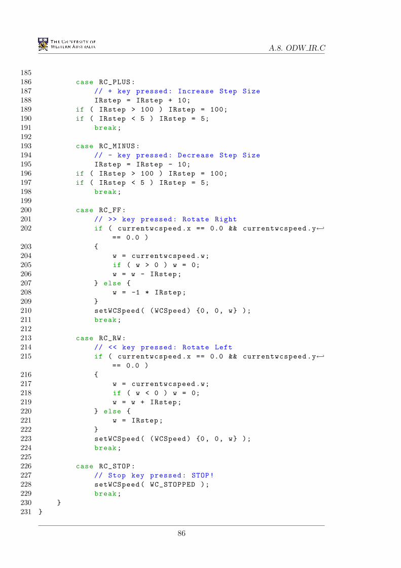
A.8. ODW IR.C
185186 case RC_PLUS:187 // + key pressed: Increase Step Size188 IRstep = IRstep + 10;189 if ( IRstep > 100 ) IRstep = 100;190 if ( IRstep < 5 ) IRstep = 5;191 break;192193 case RC_MINUS:194 // - key pressed: Decrease Step Size195 IRstep = IRstep - 10;196 if ( IRstep > 100 ) IRstep = 100;197 if ( IRstep < 5 ) IRstep = 5;198 break;199200 case RC_FF:201 // >> key pressed: Rotate Right202 if ( currentwcspeed.x == 0.0 && currentwcspeed.y←
== 0.0 )203 204 w = currentwcspeed.w;205 if ( w > 0 ) w = 0;206 w = w - IRstep;207 else 208 w = -1 * IRstep;209 210 setWCSpeed( (WCSpeed) 0, 0, w );211 break;212213 case RC_RW:214 // << key pressed: Rotate Left215 if ( currentwcspeed.x == 0.0 && currentwcspeed.y←
== 0.0 )216 217 w = currentwcspeed.w;218 if ( w < 0 ) w = 0;219 w = w + IRstep;220 else 221 w = IRstep;222 223 setWCSpeed( (WCSpeed) 0, 0, w );224 break;225226 case RC_STOP:227 // Stop key pressed: STOP!228 setWCSpeed( WC_STOPPED );229 break;230 231
86
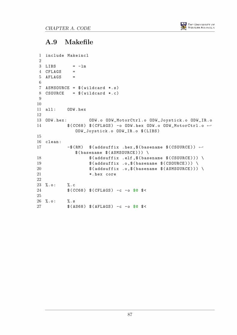
CHAPTER A. CODE
A.9 Makefile
1 include Makeincl23 LIBS = -lm4 CFLAGS =5 AFLAGS =67 ASMSOURCE = $(wildcard *.s)8 CSOURCE = $(wildcard *.c)9
1011 all: ODW.hex1213 ODW.hex: ODW.o ODW_MotorCtrl.o ODW_Joystick.o ODW_IR.o14 $(CC68) $(CFLAGS) -o ODW.hex ODW.o ODW_MotorCtrl.o ←
ODW_Joystick.o ODW_IR.o $(LIBS)1516 clean:17 -$(RM) $(addsuffix .hex ,$(basename $(CSOURCE)) ←
$(basename $(ASMSOURCE))) \18 $(addsuffix .elf ,$(basename $(CSOURCE))) \19 $(addsuffix .o,$(basename $(CSOURCE))) \20 $(addsuffix .o,$(basename $(ASMSOURCE))) \21 *.hex core2223 %.o: %.c24 $(CC68) $(CFLAGS) -c -o $@ $<2526 %.o: %.s27 $(AS68) $(AFLAGS) -c -o $@ $<
87
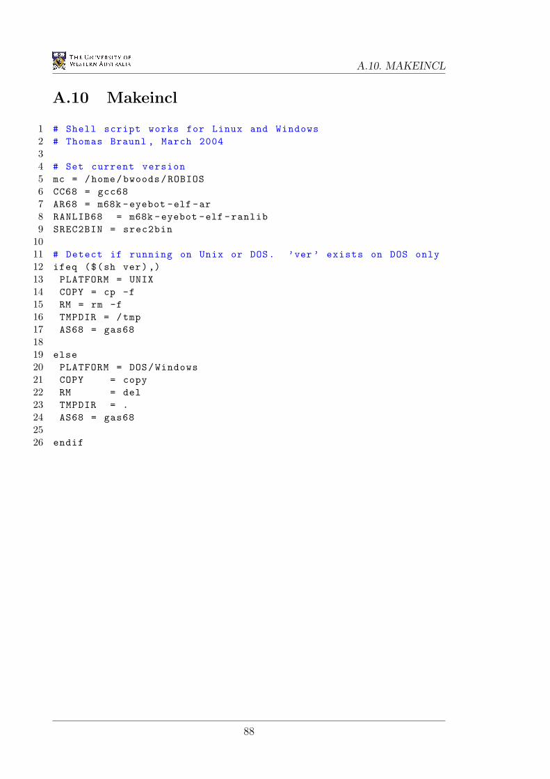
A.10. MAKEINCL
A.10 Makeincl
1 # Shell script works for Linux and Windows2 # Thomas Braunl , March 200434 # Set current version5 mc = /home/bwoods/ROBIOS6 CC68 = gcc687 AR68 = m68k -eyebot -elf -ar8 RANLIB68 = m68k -eyebot -elf -ranlib9 SREC2BIN = srec2bin
1011 # Detect if running on Unix or DOS. ’ver ’ exists on DOS only12 ifeq ($(sh ver),)13 PLATFORM = UNIX14 COPY = cp -f15 RM = rm -f16 TMPDIR = /tmp17 AS68 = gas681819 else20 PLATFORM = DOS/Windows21 COPY = copy22 RM = del23 TMPDIR = .24 AS68 = gas682526 endif
88
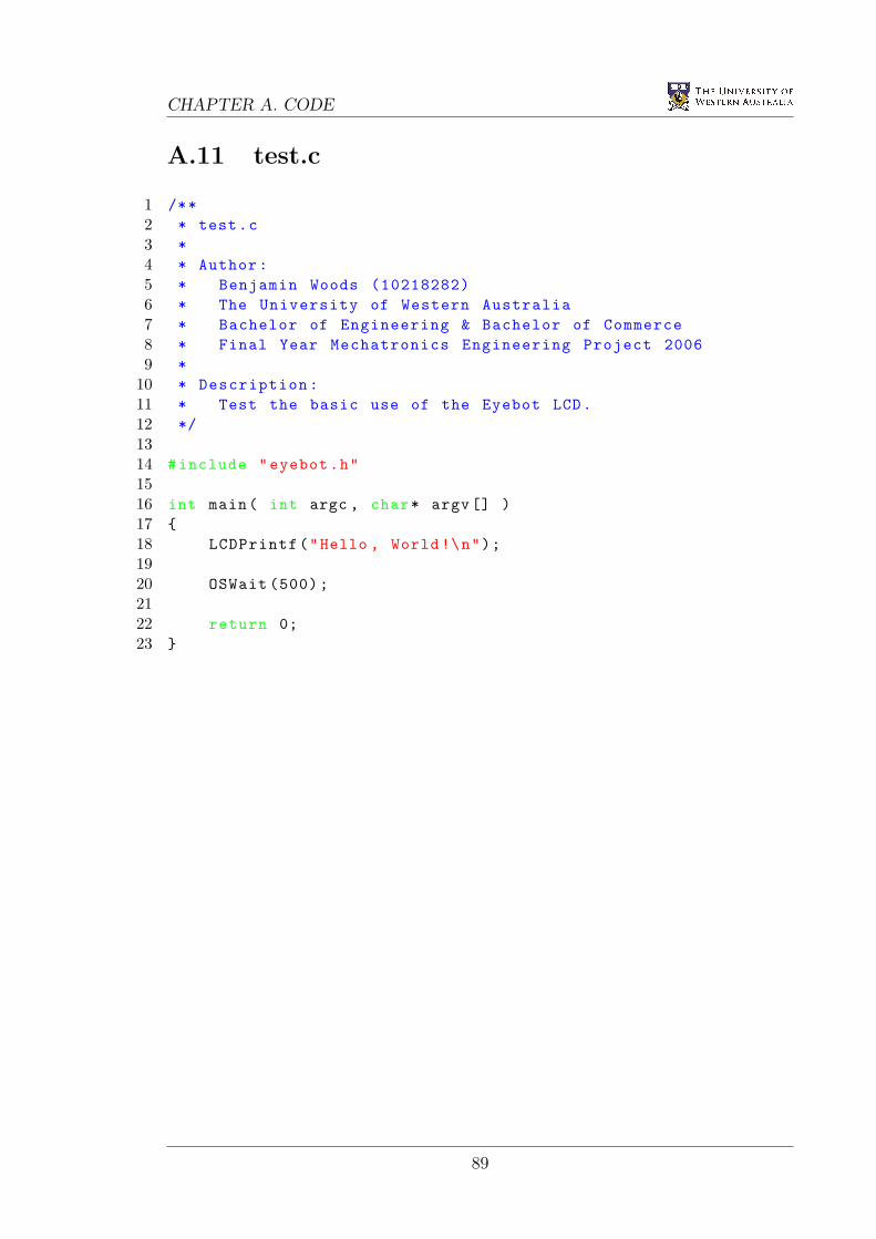
CHAPTER A. CODE
A.11 test.c
1 /**2 * test.c3 *4 * Author:5 * Benjamin Woods (10218282)6 * The University of Western Australia7 * Bachelor of Engineering & Bachelor of Commerce8 * Final Year Mechatronics Engineering Project 20069 *
10 * Description:11 * Test the basic use of the Eyebot LCD.12 */1314 #include "eyebot.h"1516 int main( int argc , char* argv[] )17 18 LCDPrintf("Hello , World !\n");1920 OSWait (500);2122 return 0;23
89

A.12. MCTEST.C
A.12 mctest.c
1 /**2 * mctest.c3 *4 * Author:5 * Benjamin Woods (10218282)6 * The University of Western Australia7 * Bachelor of Engineering & Bachelor of Commerce8 * Final Year Mechatronics Engineering Project 20069 *
10 * Description:11 * Test the communication with the Roboteq cards and the ←
resulting motor speeds12 */1314 #include "eyebot.h"1516 #define BAUD SER960017 #define HANDSHAKE NONE18 #define INTERFACE SERIAL21920 #define sccr1 0xfc0a2122 int main( int argc , char *argv[] )23 24 int key , error;25 char ch;2627 LCDClear ();28 LCDMenu("GO", "", "", "STOP");2930 LCDPrintf("Init ...\n");31 OSInitRS232( BAUD , HANDSHAKE , INTERFACE );3233 // Set RS232 on SERIAL2 to 7Bit EvenParity and 1 Stopbit34 (*((( volatile BYTE*) Ser1Base)+3)) = 0x1a;3536 // Set RS232 on SERIAL1 to 7Bit EvenParity and 1 Stopbit37 //(*(( volatile unsigned short *)sccr1)) = 0x042c;3839 do40 41 key = KEYGet ();42 while ( key != KEY1 && key != KEY4 );4344 OSWait (10);4546 if( key == KEY4 ) return 0;
90
CHAPTER A. CODE
4748 LCDPrintf("Start ...\n");4950 while( KEYRead () != KEY4 )51 52 error = OSRecvRS232 (&ch, INTERFACE);53 if( error == 0 ) LCDPutChar(ch);54 else if( error != 1 ) LCDPrintf("Error: %d\n", ←
error);55 ch = 0;5657 OSSendCharRS232(’!’, INTERFACE);58 OSSendCharRS232(’a’, INTERFACE);59 OSSendCharRS232(’5’, INTERFACE);60 OSSendCharRS232(’5’, INTERFACE);61 OSSendCharRS232(’\r’, INTERFACE);62 6364 LCDPrintf("Stop ...\n");65 OSSendCharRS232(’!’, INTERFACE);66 OSSendCharRS232(’a’, INTERFACE);67 OSSendCharRS232(’0’, INTERFACE);68 OSSendCharRS232(’0’, INTERFACE);69 OSSendCharRS232(’\r’, INTERFACE);7071 return 0;72
91
A.13. JOYTEST.C
A.13 joytest.c
1 /**2 * joytest.c3 *4 * Author:5 * Benjamin Woods (10218282)6 * The University of Western Australia7 * Bachelor of Engineering & Bachelor of Commerce8 * Final Year Mechatronics Engineering Project 20069 *
10 * Description:11 * Test the joystick by displaying readings as numbers on ←
the screen.12 * The LCD can be set (using the Eyebot keys) to display ←
either:13 * - Raw values read from the 4 potentiometers in the ←
joystick14 * - Percentage and thresholded values of the joysticks ←
position15 * - 0’s and 1’s representing the states of the 4 ←
joystick buttons16 */1718 #include "eyebot.h"19 #include <limits.h>20 #include <math.h>2122 #define BUTTON5 0x1023 #define BUTTON6 0x2024 #define BUTTON7 0x4025 #define BUTTON8 0x8026 #define X_CHANNEL 427 #define Y_CHANNEL 528 #define Z_CHANNEL 629 #define T_CHANNEL 730 #define X_THRESHOLD 1531 #define Y_THRESHOLD 1532 #define Z_THRESHOLD 153334 typedef struct35 36 int x;37 int y;38 int z;39 int t;40 JoyPos;4142 int STOP_RUNNING;
92
CHAPTER A. CODE
43 int percent , buttons;44 JoyPos MAX , MIN;4546 int button( int MASK )47 48 return (int) !(( OSReadInLatch( 0 ) & MASK)/MASK);49 5051 JoyPos joy()52 53 JoyPos joypos;5455 joypos.x = OSGetAD( X_CHANNEL );56 joypos.y = OSGetAD( Y_CHANNEL );57 joypos.z = OSGetAD( Z_CHANNEL );58 joypos.t = OSGetAD( T_CHANNEL );5960 return joypos;61 6263 void callibrate ()64 65 // Auto callibration (magic numbers)66 MIN = (JoyPos) 95, 920, 145, 1000;67 MAX = (JoyPos) 905, 75, 845, 58;6869 /*70 // Manual callibration71 LCDClear ();72 LCDPrintf ("Move joy to...\n");7374 LCDPrintf (" bottom left\n");75 LCDPrintf ("& push button 5\n");76 AUTone (5000 , 50);77 OSWait (100);78 AUTone (5000 , 50);79 OSWait (100);80 AUBeep ();81 MIN = joy();82 OSWait (300);8384 LCDPrintf ("top right\n");85 LCDPrintf ("& push button 6\n");86 AUTone (5000 , 50);87 OSWait (100);88 AUTone (5000 , 50);89 OSWait (100);90 AUBeep ();91 MAX = joy();
93
A.13. JOYTEST.C
9293 LCDPrintf ("Done!\n");94 OSWait (100);95 */96 9798 int main( int argc , char *argv[] )99
100 STOP_RUNNING = 0;101 percent = 0;102 int b5 , b6, b7, b8, key;103 JoyPos joypos;104105 while( STOP_RUNNING == 0 )106 107 LCDClear ();108 LCDMenu("RAW", "%", "BUT", "EXIT");109110 if( buttons == 0 )111 112 joypos = joy();113114 if( percent == 0 )115 116 LCDPrintf("Raw:\n");117 else 118 double x = 100*( ←
abs (200*( joypos.x-MIN.x)/(MAX.x-MIN.x) -100) ←- X_THRESHOLD )/( 100- X_THRESHOLD );
119 double y = 100*( ←abs (200*( joypos.y-MIN.y)/(MAX.y-MIN.y) -100) ←- Y_THRESHOLD )/( 100- Y_THRESHOLD );
120 double z = 100*( ←abs (200*( joypos.z-MIN.z)/(MAX.z-MIN.z) -100) ←- Z_THRESHOLD )/( 100- Z_THRESHOLD );
121122 if(x<0) x=0;123 if(y<0) y=0;124 if(z<0) z=0;125 if(x >100) x=100;126 if(y >100) y=100;127 if(z >100) z=100;128129 if(joypos.x < 500) x = -1*x;130 if(joypos.y > 500) y = -1*y;131 if(joypos.z < 500) z = -1*z;132133 joypos.x = (int) round(x);134 joypos.y = (int) round(y);
94
CHAPTER A. CODE
135 joypos.z = (int) round(z);136137 joypos.t = round (100 * (joypos.t - ←
MIN.t)/(MAX.t - MIN.t));138 if(joypos.t<0) joypos.t=0;139 if(joypos.t>100) joypos.t=100;140141 LCDPrintf("Percent :\n");142 143 LCDPrintf("X: %d\n", joypos.x);144 LCDPrintf("Y: %d\n", joypos.y);145 LCDPrintf("Z: %d\n", joypos.z);146 LCDPrintf("T: %d\n", joypos.t);147 else 148 b5 = button( BUTTON5 );149 b6 = button( BUTTON6 );150 b7 = button( BUTTON7 );151 b8 = button( BUTTON8 );152 LCDPrintf("Buttons :\n");153 LCDPrintf("B5: %d\n", b5);154 LCDPrintf("B6: %d\n", b6);155 LCDPrintf("B7: %d\n", b7);156 LCDPrintf("B8: %d\n", b8);157 if( b5 || b6 || b7 || b8 ) ←
AUTone(b5 *1000+ b6 *1500+ b7 *3000+ b8*3500, 50);158 159160 key = KEYRead ();161 switch( key )162 163 case KEY1:164 percent = 0;165 buttons = 0;166 break;167 case KEY2:168 percent = 1;169 buttons = 0;170 callibrate ();171 break;172 case KEY3:173 buttons = 1;174 percent = 0;175 break;176 case KEY4:177 STOP_RUNNING = 1;178 break;179 default:180 break;181
95
A.13. JOYTEST.C
182183 OSWait (10);184 185186 LCDPrintf("Stopping ...\n");187188 return 0;189
96
CHAPTER A. CODE
A.14 joytest2.c
1 /**2 * joytest2.c3 *4 * Author:5 * Benjamin Woods (10218282)6 * The University of Western Australia7 * Bachelor of Engineering & Bachelor of Commerce8 * Final Year Mechatronics Engineering Project 20069 *
10 * Description:11 * Test the joystick using a graphical display on the ←
Eyebot LCD.12 */1314 #include "eyebot.h"15 #include <limits.h>16 #include <math.h>1718 #define BUTTON5 0x1019 #define BUTTON6 0x2020 #define BUTTON7 0x4021 #define BUTTON8 0x802223 #define X_CHANNEL 424 #define Y_CHANNEL 525 #define Z_CHANNEL 626 #define T_CHANNEL 72728 #define X_THRESHOLD 1529 #define Y_THRESHOLD 1530 #define Z_THRESHOLD 1531 #define JOY_FREQ 100/53233 typedef struct34 35 int x;36 int y;37 int z;38 int t;39 JoyPos;4041 typedef struct42 43 BYTE b5;44 BYTE b6;45 BYTE b7;46 BYTE b8;
97
A.14. JOYTEST2.C
47 ButtonState;4849 int STOP_RUNNING;50 JoyPos JOY_MAX , JOY_MIN , JOY_CURRENT , JOY_OLD;51 ButtonState BUT_CURRENT , BUT_OLD;5253 int xy_realx( int x )54 55 return (round(x/4.0) + 32);56 5758 int xy_realy( int y )59 60 return (32 - round(y/4.0));61 6263 int z_realx( int z )64 65 return ( round(z*0.15) +83 );66 6768 int t_realy( int t )69 70 return ( 52-round(t*0.2) );71 7273 void xy_plot(int x, int y, int col)74 75 LCDSetPixel( xy_realx(x), xy_realy(y), col );76 7778 void xy_drawline( int x1 , int y1 , int x2 , int y2 , int col )79 80 LCDLine( xy_realx(x1), xy_realy(y1), xy_realx(x2), ←
xy_realy(y2), col );81 8283 void xy_drawrectangle( int x1 , int y1 , int x2, int y2, int ←
col )84 85 xy_drawline( x1, y1, x1, y2, col );86 xy_drawline( x1, y2, x2, y2, col );87 xy_drawline( x2, y2, x2, y1, col );88 xy_drawline( x2, y1, x1, y1, col );89 9091 void xy_drawcross( int x, int y, int col )92 93 xy_drawline( x-2, y-2, x+2, y+2, col );
98
CHAPTER A. CODE
94 xy_drawline( x-2, y+2, x+2, y-2, col );95 9697 void drawrectangle( int x1 , int y1 , int x2, int y2, int col )98 99 LCDLine( x1 , y1 , x1 , y2 , col );
100 LCDLine( x1 , y2 , x2 , y2 , col );101 LCDLine( x2 , y2 , x2 , y1 , col );102 LCDLine( x2 , y1 , x1 , y1 , col );103 104105 void drawmap ()106 107 xy_drawrectangle( -100, -100, 100, 100, 1 );108 xy_drawline( X_THRESHOLD , -100, X_THRESHOLD , 100, 1 );109 xy_drawline( -1*X_THRESHOLD , -100, -1*X_THRESHOLD , 100, ←
1 );110 xy_drawline( -100, Y_THRESHOLD , 100, Y_THRESHOLD , 1 );111 xy_drawline( -100, -1*Y_THRESHOLD , 100, -1*Y_THRESHOLD , ←
1 );112113 drawrectangle( 68, 12, 98, 22, 1 );114 LCDLine( z_realx (-1* Z_THRESHOLD), 12, ←
z_realx (-1* Z_THRESHOLD), 22, 1 );115 LCDLine( z_realx(Z_THRESHOLD), 12, z_realx(Z_THRESHOLD),←
22, 1 );116117 drawrectangle( 78, 52, 88, 32, 1 );118119 drawrectangle( 110, 7, 120, 17, 1 );120 drawrectangle( 110, 20, 120, 30, 1 );121 drawrectangle( 110, 34, 120, 44, 1 );122 drawrectangle( 110, 47, 120, 57, 1 );123 124125 void drawzt( int z, int t, int col )126 127 LCDLine( z_realx(z), 12, z_realx(z), 22, col );128 LCDLine( 78, t_realy(t), 88, t_realy(t), col );129 130131 void drawbuttons( BYTE b5, BYTE b6, BYTE b7, BYTE b8, int ←
col )132 133 if( b5 ) LCDArea( 111, 8, 119, 16, col );134 if( b6 ) LCDArea( 111, 21, 119, 29, col );135 if( b7 ) LCDArea( 111, 35, 119, 43, col );136 if( b8 ) LCDArea( 111, 48, 119, 56, col );137
99
A.14. JOYTEST2.C
138139 void drawreadings ()140 141 xy_drawcross( JOY_OLD.x, JOY_OLD.y, 0 );142 drawzt( JOY_OLD.z, JOY_OLD.t, 0 );143 drawbuttons( BUT_OLD.b5, BUT_OLD.b6, BUT_OLD.b7, ←
BUT_OLD.b8 , 0 );144145 drawmap ();146147 JOY_OLD.x = JOY_CURRENT.x;148 JOY_OLD.y = JOY_CURRENT.y;149 JOY_OLD.z = JOY_CURRENT.z;150 JOY_OLD.t = JOY_CURRENT.t;151152 BUT_OLD.b5 = BUT_CURRENT.b5;153 BUT_OLD.b6 = BUT_CURRENT.b6;154 BUT_OLD.b7 = BUT_CURRENT.b7;155 BUT_OLD.b8 = BUT_CURRENT.b8;156157 xy_drawcross( JOY_OLD.x, JOY_OLD.y, 1 );158 drawzt( JOY_OLD.z, JOY_OLD.t, 1 );159 drawbuttons( BUT_OLD.b5, BUT_OLD.b6, BUT_OLD.b7, ←
BUT_OLD.b8 , 1 );160 161162 void button_beep ()163 164 if( BUT_CURRENT.b5 || BUT_CURRENT.b6 || BUT_CURRENT.b7 ←
|| BUT_CURRENT.b8 )165 AUTone(BUT_CURRENT.b5 *1000+ BUT_CURRENT.b6 *1500+ BUT_CURRENT.b7 *3000+ BUT_CURRENT.b8*3500,←
50);166 167168 void joy_update ()169 170 BUT_CURRENT.b5 = !(( OSReadInLatch( 0 ) & ←
BUTTON5)/BUTTON5);171 BUT_CURRENT.b6 = !(( OSReadInLatch( 0 ) & ←
BUTTON6)/BUTTON6);172 BUT_CURRENT.b7 = !(( OSReadInLatch( 0 ) & ←
BUTTON7)/BUTTON7);173 BUT_CURRENT.b8 = !(( OSReadInLatch( 0 ) & ←
BUTTON8)/BUTTON8);174175 JOY_CURRENT.x = 200*( OSGetAD( X_CHANNEL ) - ←
JOY_MIN.x)/( JOY_MAX.x - JOY_MIN.x) - 100;176 JOY_CURRENT.y = 200*( OSGetAD( Y_CHANNEL ) - ←
JOY_MIN.y)/( JOY_MAX.y - JOY_MIN.y) - 100;
100
CHAPTER A. CODE
177 JOY_CURRENT.z = 200*( OSGetAD( Z_CHANNEL ) - ←JOY_MIN.z)/( JOY_MAX.z - JOY_MIN.z) - 100;
178 JOY_CURRENT.t = 100*( OSGetAD( T_CHANNEL ) - ←JOY_MIN.t)/( JOY_MAX.t - JOY_MIN.t);
179 180181 void callibrate ()182 183 // Auto callibration (magic numbers)184 JOY_MIN = (JoyPos) 95, 920, 145, 1000;185 JOY_MAX = (JoyPos) 905, 75, 845, 58;186187 /*188 // Manual callibration189 LCDClear ();190 LCDPrintf ("Move joy to...\n");191192 LCDPrintf (" bottom left\n");193 LCDPrintf ("& push button 5\n");194 AUTone (5000 , 50);195 OSWait (100);196 AUTone (5000 , 50);197 OSWait (100);198 AUBeep ();199 JOY_MIN .= joy();200 OSWait (300);201202 LCDPrintf ("top right\n");203 LCDPrintf ("& push button 6\n");204 AUTone (5000 , 50);205 OSWait (100);206 AUTone (5000 , 50);207 OSWait (100);208 AUBeep ();209 JOY_MAX .= joy();210211 LCDPrintf ("Done!\n");212 OSWait (100);213 */214 215216 int main( int argc , char *argv[] )217 218 STOP_RUNNING = 0;219 int key = 0;220221 callibrate ();222
101
A.14. JOYTEST2.C
223 TimerHandle joyHandle = OSAttachTimer( JOY_FREQ , ←joy_update );
224225 while( STOP_RUNNING == 0 )226 227 button_beep ();228229 drawreadings ();230231 key = KEYRead ();232 if( key == KEY4 ) STOP_RUNNING = 1;233234 OSWait (15);235 236237 LCDPrintf("Stopping ...\n");238 OSDetachTimer( joyHandle );239240 return 0;241
102
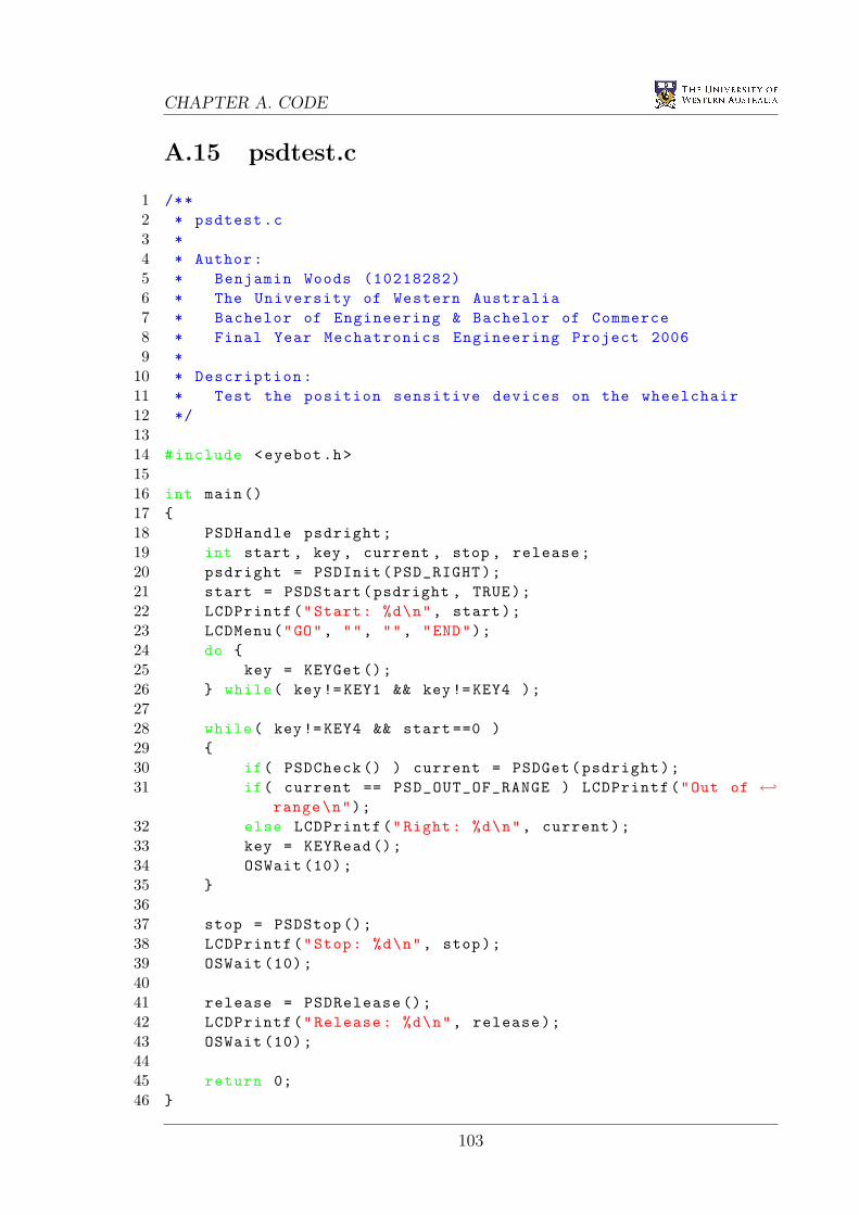
CHAPTER A. CODE
A.15 psdtest.c
1 /**2 * psdtest.c3 *4 * Author:5 * Benjamin Woods (10218282)6 * The University of Western Australia7 * Bachelor of Engineering & Bachelor of Commerce8 * Final Year Mechatronics Engineering Project 20069 *
10 * Description:11 * Test the position sensitive devices on the wheelchair12 */1314 #include <eyebot.h>1516 int main()17 18 PSDHandle psdright;19 int start , key , current , stop , release;20 psdright = PSDInit(PSD_RIGHT);21 start = PSDStart(psdright , TRUE);22 LCDPrintf("Start: %d\n", start);23 LCDMenu("GO", "", "", "END");24 do 25 key = KEYGet ();26 while( key!=KEY1 && key!=KEY4 );2728 while( key!=KEY4 && start ==0 )29 30 if( PSDCheck () ) current = PSDGet(psdright);31 if( current == PSD_OUT_OF_RANGE ) LCDPrintf("Out of ←
range\n");32 else LCDPrintf("Right: %d\n", current);33 key = KEYRead ();34 OSWait (10);35 3637 stop = PSDStop ();38 LCDPrintf("Stop: %d\n", stop);39 OSWait (10);4041 release = PSDRelease ();42 LCDPrintf("Release: %d\n", release);43 OSWait (10);4445 return 0;46
103

A.15. PSDTEST.C
104
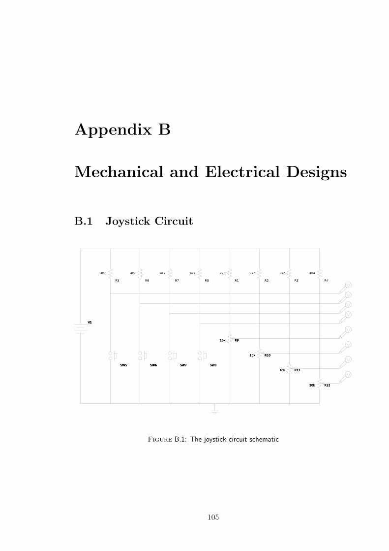
Appendix B
Mechanical and Electrical Designs
B.1 Joystick Circuit
6O 6O 6O
6
O
6O 6O 6O
6
O
6O 6O 6O
6
O
6
O
6
O
6
O
6
O
6O 6O 6O
7;7;7;7;7;7;
6
O
7;7;7;7;7;7;7;7;7;7;7;7;7;7;7;7;7;7;
::::::
Figure B.1: The joystick circuit schematic
105
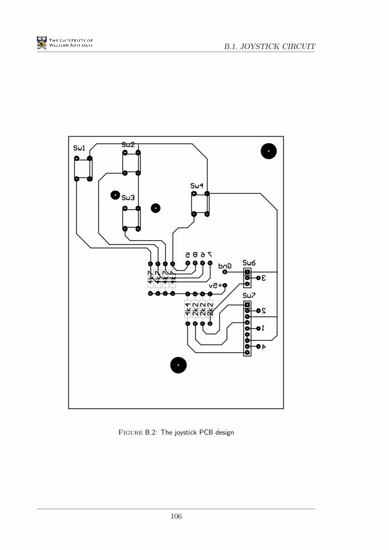
B.1. JOYSTICK CIRCUIT
Figure B.2: The joystick PCB design
106
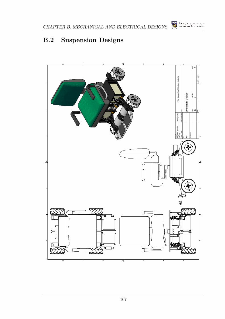
CHAPTER B. MECHANICAL AND ELECTRICAL DESIGNS
B.2 Suspension Designs1 1
2 2
3 3
4 4
AA
BB
CC
DD
SHEET 1 OF 1
DRAWN
CHECKED
QA
MFG
APPROVED
Benjamin W
oods
Chris Croft
21/08/2006
21/08/2006
DWG NO
1
TITLE
Wheelchair Design
SIZE
CSCALE
The University of Western Australia
REV
B
107
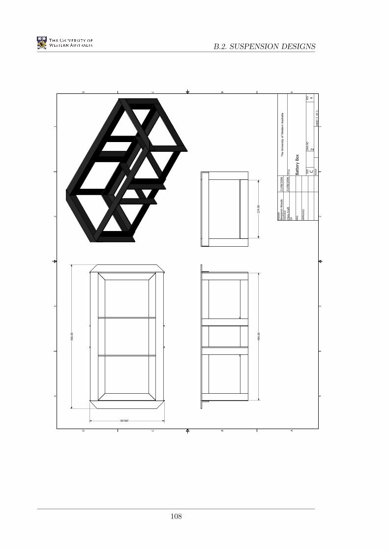
B.2. SUSPENSION DESIGNS1 1
2 2
3 3
4 4
AA
BB
CC
DD
SHEET 1 OF 1
DRAWN
CHECKED
QA
MFG
APPROVED
Benjamin W
oods
Chris Croft
21/08/2006
21/08/2006
DWG NO
2
TITLE
Battery Box
SIZE
CSCALE
The University of Western Australia
REV
B
290.00
560.00
494.00
224.00
108
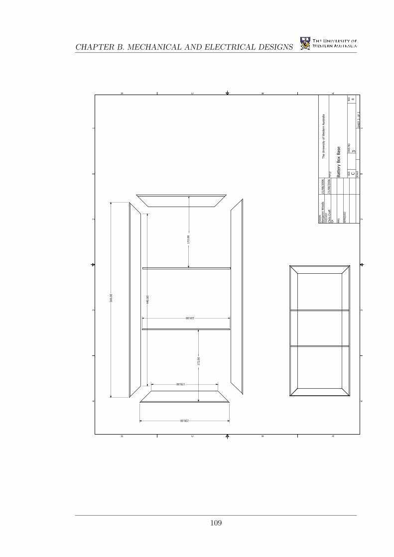
CHAPTER B. MECHANICAL AND ELECTRICAL DESIGNS
1 1
2 2
3 3
4 4
AA
BB
CC
DD
SHEET 1 OF 1
DRAWN
CHECKED
QA
MFG
APPROVED
Benjamin W
oods
Chris Croft
21/08/2006
21/08/2006
DWG NO
3
TITLE
Battery Box Base
SIZE
CSCALE
The University of Western Australia
REV
B
500.00
170.00
440.00
224.00
172.00
172.00
230.00
109
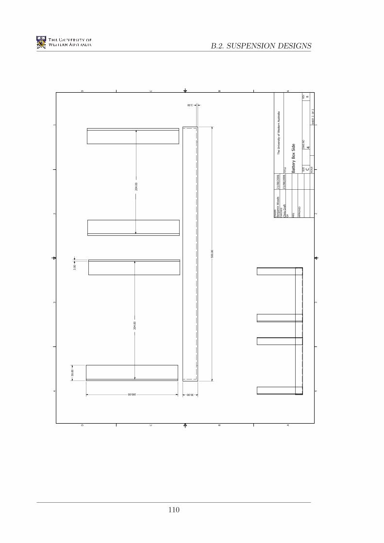
B.2. SUSPENSION DESIGNS1 1
2 2
3 3
4 4
AA
BB
CC
DD
SHEET 1 OF 1
DRAWN
CHECKED
QA
MFG
APPROVED
Benjamin W
oods
Chris Croft
21/08/2006
21/08/2006
DWG NO
4
TITLE
Battery Box Side
SIZE
CSCALE
The University of Western Australia
REV
B
204.00
204.00
500.00
180.00
30.00
30.00
3.00
3.00
110
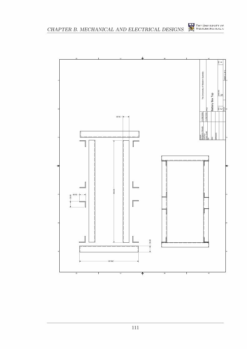
CHAPTER B. MECHANICAL AND ELECTRICAL DESIGNS
1 1
2 2
3 3
4 4
AA
BB
CC
DD
SHEET 1 OF 1
DRAWN
CHECKED
QA
MFG
APPROVED
Benjamin W
oods
Chris Croft
21/08/2006
21/08/2006
DWG NO
5
TITLE
Battery Box Top
SIZE
CSCALE
The University of Western Australia
REV
B
290.00
500.00
30.00
30.00
30.00
30.00
111
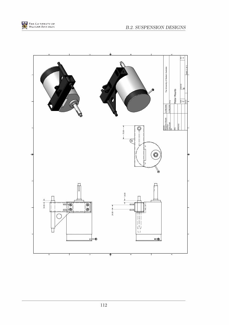
B.2. SUSPENSION DESIGNS1 1
2 2
3 3
4 4
AA
BB
CC
DD
SHEET 1 OF 1
DRAWN
CHECKED
QA
MFG
APPROVED
Benjamin W
oods
Chris Croft
21/08/2006
21/08/2006
DWG NO
6
TITLE
Motor Mounts
SIZE
CSCALE
The University of Western Australia
REV
B
10.00
70.00
10.00
24.00
112
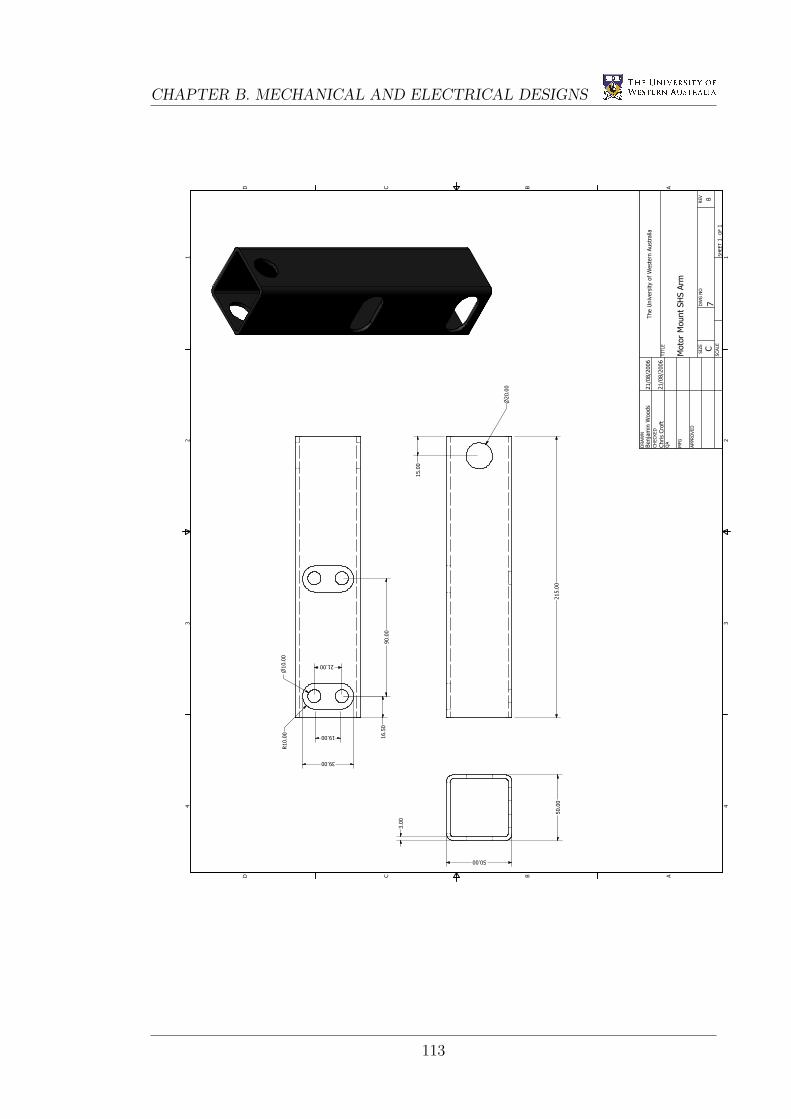
CHAPTER B. MECHANICAL AND ELECTRICAL DESIGNS
1 1
2 2
3 3
4 4
AA
BB
CC
DD
SHEET 1 OF 1
DRAWN
CHECKED
QA
MFG
APPROVED
Benjamin W
oods
Chris Croft
21/08/2006
21/08/2006
DWG NO
7
TITLE
Motor Mount SHS Arm
SIZE
CSCALE
The University of Western Australia
REV
B
215.00
50.00
50.00
3.00
n20.00
39.00
19.00
n10.00
R10.00
21.00
16.50
90.00
15.00
113
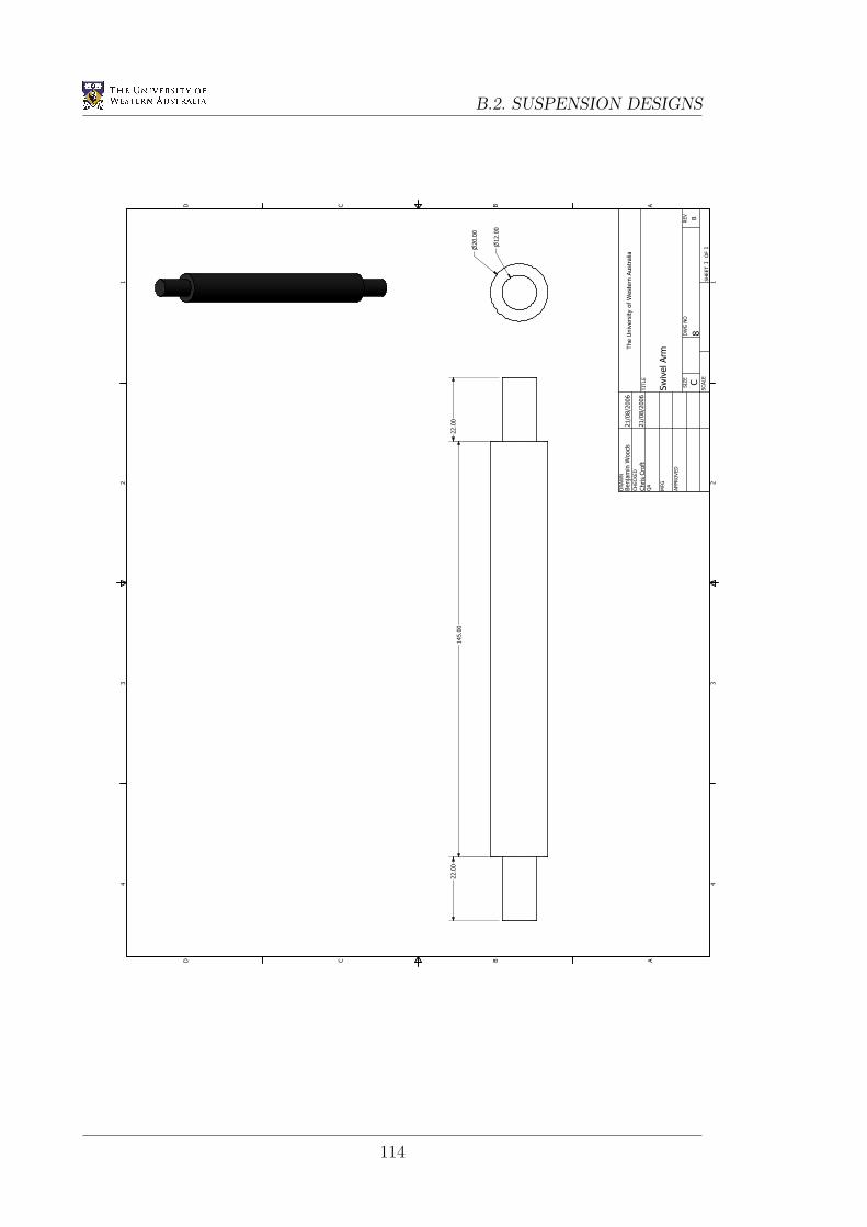
B.2. SUSPENSION DESIGNS1 1
2 2
3 3
4 4
AA
BB
CC
DD
SHEET 1 OF 1
DRAWN
CHECKED
QA
MFG
APPROVED
Benjamin W
oods
Chris Croft
21/08/2006
21/08/2006
DWG NO
8
TITLE
Swivel Arm
SIZE
CSCALE
The University of Western Australia
REV
B
n20.00
n12.00
145.00
22.00
22.00
114
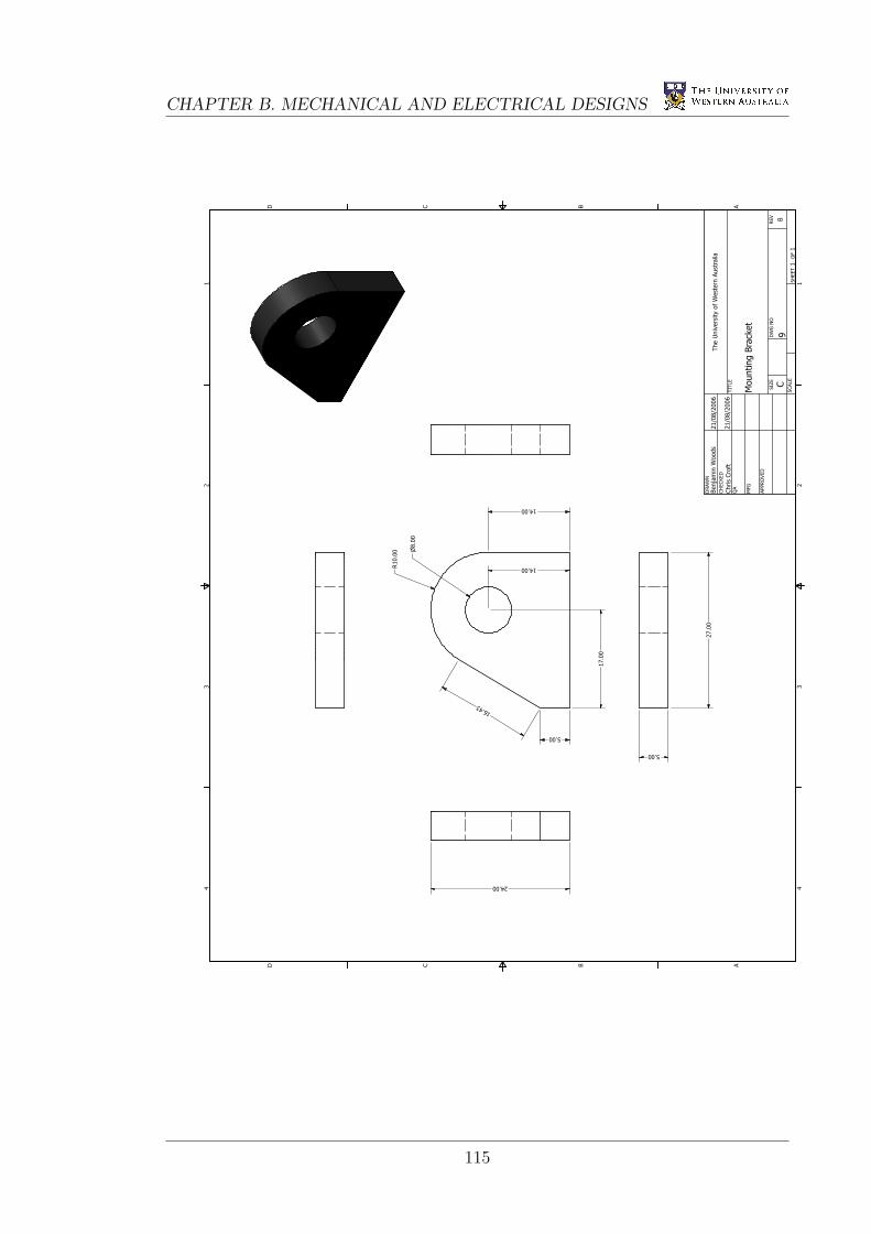
CHAPTER B. MECHANICAL AND ELECTRICAL DESIGNS
1 1
2 2
3 3
4 4
AA
BB
CC
DD
SHEET 1 OF 1
DRAWN
CHECKED
QA
MFG
APPROVED
Benjamin W
oods
Chris Croft
21/08/2006
21/08/2006
DWG NO
9
TITLE
Mounting Bracket
SIZE
CSCALE
The University of Western Australia
REV
B
27.00
5.00
n8.00
R10.00
16.43
5.00
14.00
24.00
17.00
14.00
115
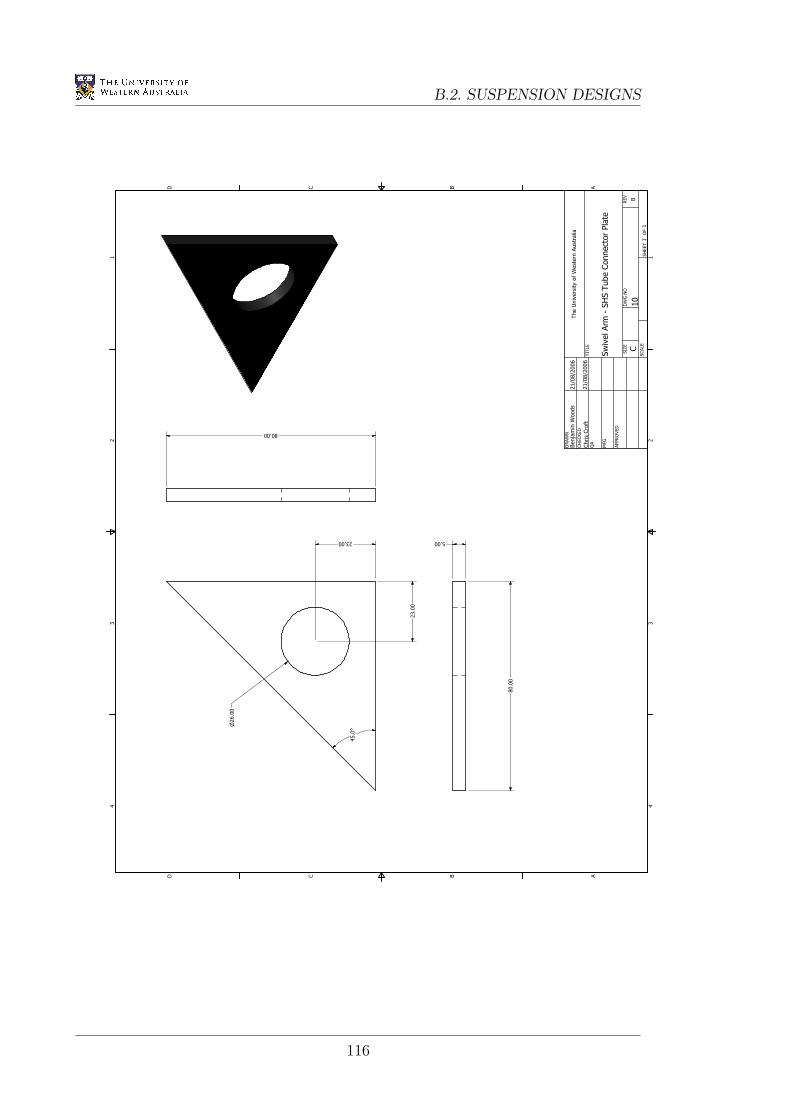
B.2. SUSPENSION DESIGNS1 1
2 2
3 3
4 4
AA
BB
CC
DD
SHEET 1 OF 1
DRAWN
CHECKED
QA
MFG
APPROVED
Benjamin W
oods
Chris Croft
21/08/2006
21/08/2006
DWG NO
10
TITLE
Swivel Arm
- SHS Tube Connector Plate
SIZE
CSCALE
The University of Western Australia
REV
B
80.00
80.00
n26.00
45.0°
23.00
23.00 5.00
116
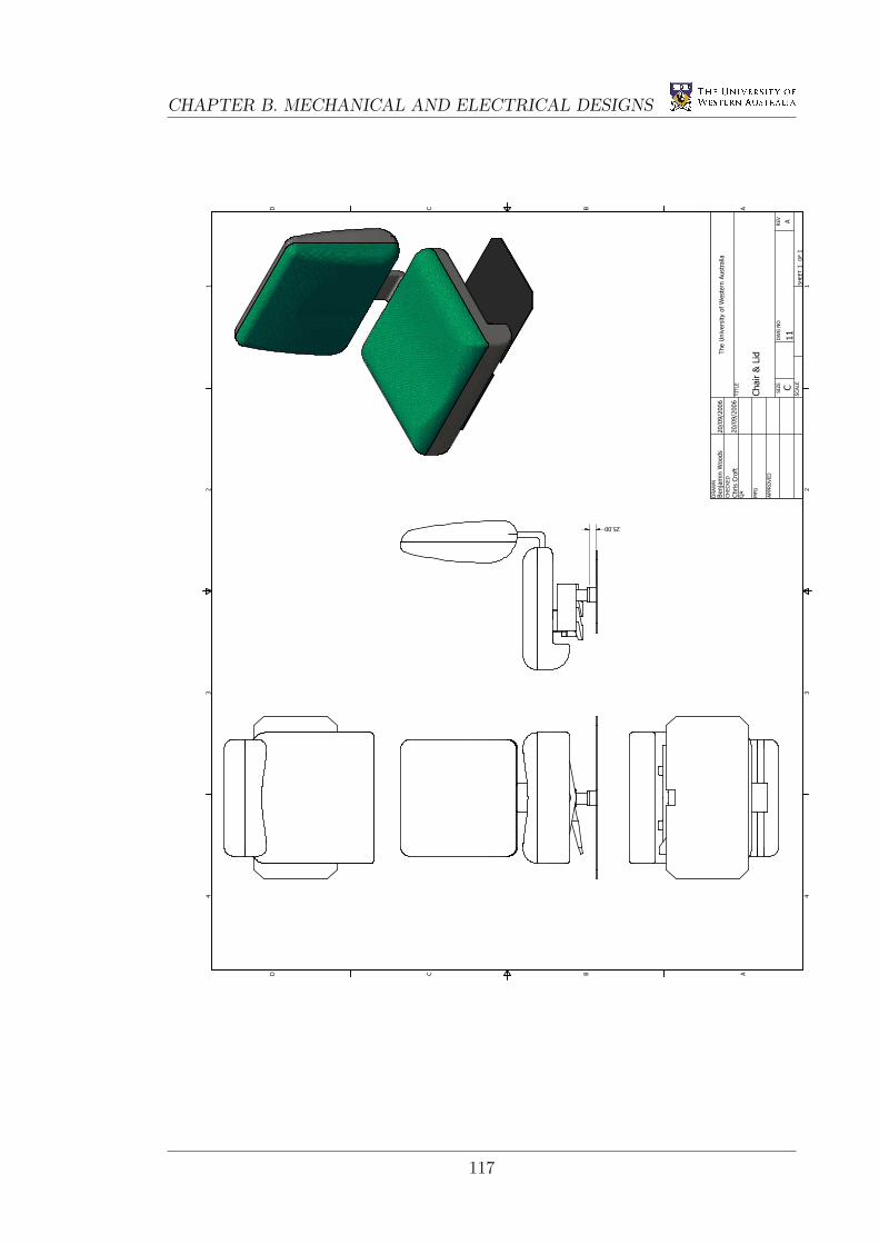
CHAPTER B. MECHANICAL AND ELECTRICAL DESIGNS
1 1
2 2
3 3
4 4
AA
BB
CC
DD
SHEET 1 OF 1
DRAWN
CHECKED
QA
MFG
APPROVED
Benjamin W
oods
Chris Croft
20/09/2006
20/09/2006
DWG NO
11
TITLE
Chair & Lid
SIZE
CSCALE
The University of Western Australia
REV
A
25.00
117
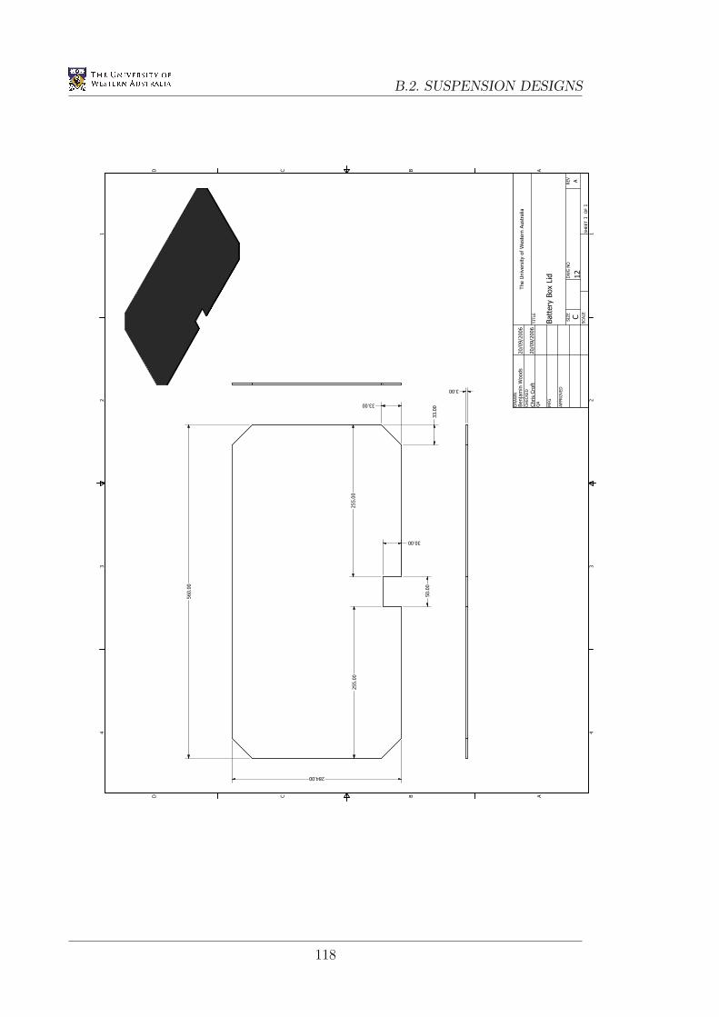
B.2. SUSPENSION DESIGNS1 1
2 2
3 3
4 4
AA
BB
CC
DD
SHEET 1 OF 1
DRAWN
CHECKED
QA
MFG
APPROVED
Benjamin W
oods
Chris Croft
20/09/2006
20/09/2006
DWG NO
12
TITLE
Battery Box Lid
SIZE
CSCALE
The University of Western Australia
REV
A
560.00
284.00
50.00
30.00
33.00
33.00
3.00
255.00
255.00
118
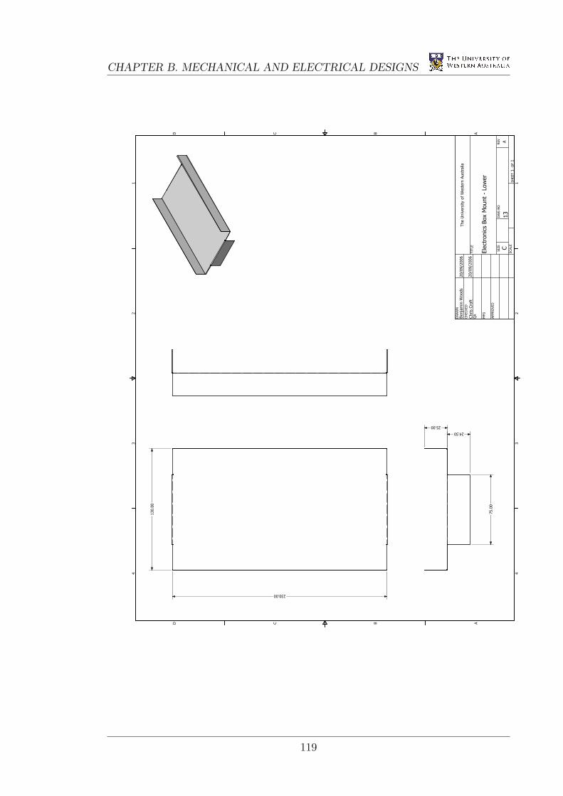
CHAPTER B. MECHANICAL AND ELECTRICAL DESIGNS
1 1
2 2
3 3
4 4
AA
BB
CC
DD
SHEET 1 OF 1
DRAWN
CHECKED
QA
MFG
APPROVED
Benjamin W
oods
Chris Croft
20/09/2006
20/09/2006
DWG NO
13
TITLE
Electronics Box Mount - Lower
SIZE
CSCALE
The University of Western Australia
REV
A
230.00
130.00
24.50
25.00
75.00
119
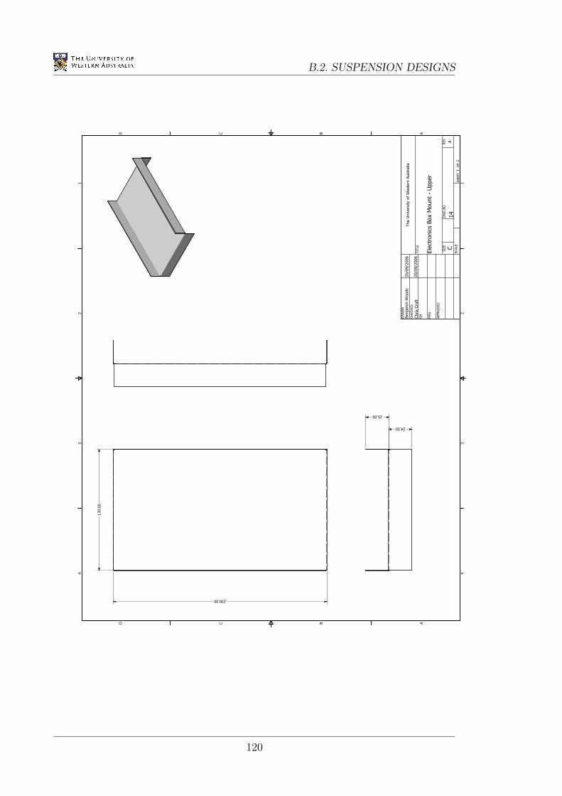
B.2. SUSPENSION DESIGNS1 1
2 2
3 3
4 4
AA
BB
CC
DD
SHEET 1 OF 1
DRAWN
CHECKED
QA
MFG
APPROVED
Benjamin W
oods
Chris Croft
20/09/2006
20/09/2006
DWG NO
14
TITLE
Electronics Box Mount - Upper
SIZE
CSCALE
The University of Western Australia
REV
A
230.00
130.00
24.50
25.00
120

Appendix C
Information and Brochures
121
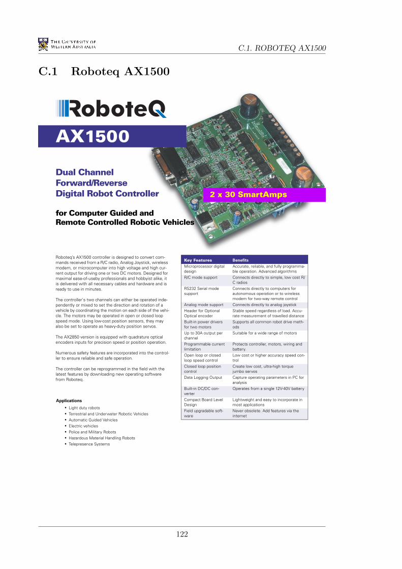
C.1. ROBOTEQ AX1500
C.1 Roboteq AX1500
Dual ChannelForward/ReverseDigital Robot Controller
for Computer Guided andRemote Controlled Robotic Vehicles
AX1500
Key Features Benefits
Microprocessor digital design
Accurate, reliable, and fully programma-ble operation. Advanced algorithms
R/C mode support Connects directly to simple, low cost R/C radios
RS232 Serial mode support
Connects directly to computers for autonomous operation or to wireless modem for two-way remote control
Analog mode support Connects directly to analog joystickHeader for Optional Optical encoder
Stable speed regardless of load. Accu-rate measurement of travelled distance
Built-in power drivers for two motors
Supports all common robot drive meth-ods
Up to 30A output per channel
Suitable for a wide range of motors
Programmable current limitation
Protects controller, motors, wiring and battery.
Open loop or closed loop speed control
Low cost or higher accuracy speed con-trol
Closed loop position control
Create low cost, ultra-high torque jumbo servos
Data Logging Output Capture operating parameters in PC for analysis
Built-in DC/DC con-verter
Operates from a single 12V-40V battery
Compact Board Level Design
Lightweight and easy to incorporate in most applications
Field upgradable soft-ware
Never obsolete. Add features via the internet
Roboteq’s AX1500 controller is designed to convert com-mands received from a R/C radio, Analog Joystick, wireless modem, or microcomputer into high voltage and high cur-rent output for driving one or two DC motors. Designed for maximal ease-of-useby professionals and hobbyist alike, it is delivered with all necessary cables and hardware and is ready to use in minutes.
The controller's two channels can either be operated inde-pendently or mixed to set the direction and rotation of a vehicle by coordinating the motion on each side of the vehi-cle. The motors may be operated in open or closed loop speed mode. Using low-cost position sensors, they may also be set to operate as heavy-duty position servos.
The AX2850 version is equipped with quadrature optical encoders inputs for precision speed or position operation.
Numerous safety features are incorporated into the control-ler to ensure reliable and safe operation.
The controller can be reprogrammed in the field with the latest features by downloading new operating software from Roboteq.
Applications
• Light duty robots• Terrestrial and Underwater Robotic Vehicles• Automatic Guided Vehicles• Electric vehicles• Police and Military Robots• Hazardous Material Handling Robots• Telepresence Systems
2 x 30 SmartAmps
122
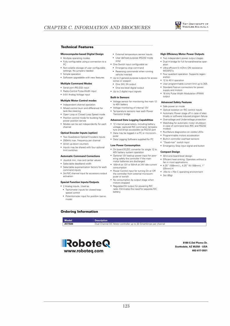
CHAPTER C. INFORMATION AND BROCHURES
Model Description
AX1500 Dual Channel DC Motor controller up to 30 SmartAmps per channel
Microcomputer-based Digital Design
• Multiple operating modes• Fully configurable using a connection to a
PC• Non-volatile storage of user configurable
settings. No jumpers needed• Simple operation• Software upgradable with new features
Multiple Command Modes
• Serial port (RS-232) input• Radio-Control Pulse-Width input• 0-5V Analog Voltage input
Multiple Motor Control modes
• Independent channel operation• Mixed control (sum and difference) for
tank-like steering• Open Loop or Closed Loop Speed mode• Position control mode for building high
power position servos• Modes can be set independently for each
channel
Optical Encoder Inputs (option)
• Two Quadrature Optical Encoders inputs• 250kHz max. frequency per channel• 32-bit up-down counters• Inputs may be shared with four optional
limit switches
Automatic Command Corrections
• Joystick min, max and center values• Selectable deadband width• Selectable exponentiation factors for each
command inputs• 3rd R/C channel input for accessory output
activation
Special Function Inputs/Outputs
• 2 Analog inputs. Used as • Tachometer inputs for closed loop
speed control• Potentiometer input for position (servo
mode)
• External temperature sensor inputs
• User defined purpose (RS232 mode only)
• One Switch input configurable as • Emergency stop command
• Reversing commands when running vehicle inverted
• Up to 2 general purpose outputs for acces-sories or weapon• One 24V, 2A output
• One low-level digital output
• Up to 2 digital input signals
Built-in Sensors
• Voltage sensor for monitoring the main 12 to 40V battery
• Voltage monitoring of internal 12V• Temperature sensors near each Power
Transistor bridge
Advanced Data Logging Capabilities
• 12 internal parameters, including battery voltage, captured R/C command, tempera-ture and Amps accessible via RS232 port
• Data may be logged in a PC or microcom-puter
• Data Logging Software supplied for PC
Low Power Consumption
• On board DC/DC converter for single 12 to 40V battery system operation
• Optional 12V backup power input for pow-ering safely the controller if the main motor batteries are discharged
• 100mA at 12V or 50mA at 24V idle current consumption
• Power Control input for turning On or Off the controller from external microcom-puter or switch
• No consumption by output stage when motors stopped
• Regulated 5V output for powering R/C radio. Eliminates the need for separate R/C battery.
High Efficiency Motor Power Outputs
• Two independent power output stages• Dual H bridge for full forward/reverse oper-
ation• Ultra-efficient 5 mOhm ON resistance
MOSFETs • Four quadrant operation. Supports regen-
eration• 12 to 40 V operation• User programmable current limit up to 30A• Standard Fast-on connectors for power
supply and motors• 16 kHz Pulse Width Modulation (PWM)
output
Advanced Safety Features
• Safe power on mode• Optical isolation on R/C control inputs• Automatic Power stage off in case of elec-
trically or software induced program failure• Overvoltage and Undervoltage protection• Watchdog for automatic motor shutdown
in case of command loss (R/C and RS232 modes)
• Run/failure diagnostics on visible LEDs• Programmable motors acceleration• Built-in controller overheat sensors• “Dead-man” switch input• Emergency Stop input signal and button
Compact Design
• All-in-one board-level design.• Efficient heat sinking. Operates without a
fan in most applications.• 4.25” (108mm) L, 4.25” W (108mm), 1”
(25mm) H• -20o to +70o C operating environment • 3oz (85g)
Technical Features
Ordering Information
www.roboteq.com
8180 E.Del Plomo Dr.
Scottsdale, AZ 85258 - USA
602-617-3931
123