Embed Size (px)
Citation preview

1
For final production, import color definitions from\\daldoc01\docteam\templates\framemaker\book-template\color-defs\ production-colors.fm. Do not import other template elements such as page layout.
To return to the draft version, import color def’ns from draft-colors.fm.To switch to the beta version, import color def’ns from beta-colors.fm
OmniAccess 780Hardware Users Guide
2
Release 2.2Beta
Notes on numbered items on banner & legal pages1 26801 West Agoura Road
Calabasas, CA 91301
(818) 880-3500
FAX (818) 880-3505
US Customer Support—(800) 995-2696
International Customer Support—(818) 878-4507
Internet—service.esd.alcatel-lucent.com
Website: www.alcatel-lucent.com
Part No: 032289-00, Rev. A

Copyright
The Specifications and Information regarding the products in this manual are subject to change without notice. All statements, information, and recommendations in this manual are believed to be accurate but are presented without warranty of any kind, express or implied. Users must take full responsibility for their application of any products.
THE SOFTWARE LICENSE AND LIMITED WARRANTY FOR THE ACCOMPANYING PRODUCT ARE SET FORTH IN THE INFORMATION PACKET THAT SHIPPED WITH THE PRODUCT AND ARE INCORPORATED HEREIN BY THIS REFERENCE.
This equipment has been tested and found to comply within the limits pursuant to the (Centre for Telecom) rules. These limits are designed to provide protection against harmful interference when the equipment is operated in a commercial environment.
The following information is for the Users of the OmniAccess 780: If it is not installed in accordance with the installation instructions, it may not function exactly to the said specifications. Modifying the equipment without Alcatel-Lucent's written authorization may result in the equipment no longer complying with the said dimensions.
Copyright © 2007, Alcatel-Lucent. All rights reserved.
Not withstanding any other warranty herein, all hardware and software are provided "as is" with all faults. Alcatel-Lucent disclaim all warranties, expressed or implied, including, without limitation, those of merchantability, fitness for a particular purpose and non-infringement or arising from a course of dealing, usage, or trade practice. In no event shall Alcatel-Lucent be liable for any indirect, special, consequential, or incidental damages, including, without limitation, lost profits or loss or damage to data arising out of the use or inability to use this manual, even if Alcatel-Lucent have been advised of the possibility of such damages.
34
5
Table of Contents
1 Preface............................................................................................................ 3About This Guide ......................................................................................................................3Chapter Description ..................................................................................................................3Audience ...................................................................................................................................3Document Organization ............................................................................................................4Document Conventions.............................................................................................................4Obtaining Documentation..........................................................................................................5Reference Publications .............................................................................................................5Obtaining Technical Assistance ................................................................................................5Documentation Feedback .........................................................................................................5
2 OmniAccess 780 Overview........................................................................... 7Introduction ...............................................................................................................................7OA-780 Overview......................................................................................................................8Package Contents.....................................................................................................................8Hardware Overview...................................................................................................................9
The OA-780 ........................................................................................................................9User Modules ...................................................................................................................16
System Specifications .............................................................................................................31Valid System Configuration ..............................................................................................32
3 Installing the OmniAccess 780................................................................... 33Preparing for Installation .........................................................................................................34
Required Tools and Equipment ........................................................................................34Installation Checklist ...............................................................................................................35Safety Measures .....................................................................................................................36
Preventing Injury...............................................................................................................36Equipment Guidelines ......................................................................................................36Lifting Safely .....................................................................................................................37Safety With Electricity .......................................................................................................38Preventing Electrostatic Discharge Damage ....................................................................39
Site Requirement Guidelines ..................................................................................................40Power Supply Overview..........................................................................................................41
Power Supply Specifications ............................................................................................41Plant Wiring ......................................................................................................................43
General Installation .................................................................................................................44Rack-Mounting the OA-780.....................................................................................................45
Parts Required..................................................................................................................46Installing the OA-780 in the Rack .....................................................................................47
Installing User Modules...........................................................................................................48Installing Switch Fabric .....................................................................................................48Installing Line Cards .........................................................................................................49Installing Fan Tray ............................................................................................................51

Installing Power Tray ........................................................................................................52Installing Fillers .................................................................................................................53
4 Starting the OmniAccess 780......................................................................55Introduction .............................................................................................................................55Checking Conditions Prior to System Startup .........................................................................56Starting the OA-780 ................................................................................................................56Connecting to the System Console Port .................................................................................59Performing Basic Configuration Tasks....................................................................................61
Accessing OA-780 Through CLI.......................................................................................61Connecting the System to the Network...................................................................................67
Connecting Through the Internal Network........................................................................67Connecting Through External Network.............................................................................70
Site Log...................................................................................................................................71
Appendix A Regulatory Compliance and Safety Information..........................1Declaration of Conformity: CE Mark..........................................................................................1
Waste Electrical and Electronic Equipment (WEEE) Statement ........................................2China RoHS: Hazardous Substance Table...............................................................................3Standards Compliance..............................................................................................................5
Safety .................................................................................................................................5EMC....................................................................................................................................5Telecom..............................................................................................................................5Declaration of Conformity Addendum.................................................................................6FCC Class A, Part 15 .........................................................................................................7Canada Class A Statement ................................................................................................8JATE...................................................................................................................................8CISPR22 Class A warning..................................................................................................8VCCI ...................................................................................................................................8Class A Warning for Taiwan and Other Chinese Markets ..................................................9
Translated Safety Warnings....................................................................................................10Instrucciones de seguridad en español...................................................................................16
Appendix B AC Power Specifications..............................................................19
Appendix C Pin Connector Details for OmniAccess 780 ...............................21RJ-11 Modem Connector Pin Assignments......................................................................21RJ-45 Console Connector Pin Assignments ....................................................................22T1E1 Connector Pin Assignments....................................................................................23SE/L2GE Connector Pin Assignments .............................................................................24Serial Card (V.35/X.21) Connector Pin Assignments .......................................................25

List of Figures
The OA-780 Chassis 10Air Flow Through the OA-780 11Front Panel 12Rear Panel 12OA-780 (8-Slot Chassis) 13Switch Fabric 16Services Engine 174-port T1E1 Line Card 19GigE Line Card 21Serial Line Card (V.35/X.21) 24Fan Tray 27Ports on Fan Tray 28Power Tray 30Connecting Power Cord 42Rack Mounting the OA-780 47Installing Switch Fabric 48Installing Services Engine 49Installing Line Cards 50Installing Fan Tray 51Installing Power Tray 52Connecting to the System Console 59Connecting to Internal Network 68Connecting through External Network 70RJ-11 Connector 21RJ-45 Connector 22Serial Card (V.35/X.21) Connector 25


List of Tables
OA-780 Chassis Physical Specifications 11Slot Numbers 13LED Status Table 14Cable Connections Table 15Switch Fabric LEDs 16SE Card LEDs 18LEDs for Ethernet Port on SE Card 18T1/ E1 Card LEDs 20T1/ E1 Port LEDs 20T1E1 Mode LEDs 21GigE Card LEDs 22LEDs for each Port on GigE Card 22Serial Card (V.35/X.21) LEDs 25Serial (V.35/X.21) Port LEDs 25Serial Card (V.35/X.21) Cable Part Numbers 26Fan Tray LEDs 29Environmental Specifications 31Power Specifications 31Physical Specifications 31Valid System Configuration 32Environmental Site Requirements 40LED Status 57Console Properties 60AC Power Supply Specifications 19Pin Connector Details for RJ-11 Connector 21Pin Connector Details for RJ-45 Connector 22T1/E1 Card Port Connector Pin Assignment 2310/100/1000 Mbps Port Connector Pin Assignment on SE/L2GE Card 24Pin Connector Details for Serial Line Card 25


For final production, import color definitions from\\daldoc01\docteam\templates\framemaker\book-template\color-defs\ production-colors.fm. Do not import other template elements such as page layout.
To return to the draft version, import color def’ns from draft-colors.fm.To switch to the beta version, import color def’ns from beta-colors.fm
Optional footer: Manual title (to set, redefine ManualTitlevariable)
CHAPTER 1
agination: umeric & ntinuous
PNco
PREFACE
ABOUT THIS GUIDEThis hardware users guide explains the initial hardware installation and configuration procedures for the OmniAccess 780 (OA-780). It contains procedures for unpacking and installing the OA-780 hardware, starting up the system, and creating a basic configuration. After completing the installation and basic configuration procedures covered in this guide, use the appropriate companion publications to completely configure your system.
CHAPTER DESCRIPTIONThis chapter explains the objectives, intended audience, and organization of the OA-780 Hardware Users Guide, and defines the conventions used to convey instructions and information.
AUDIENCEThis book is intended for networking professionals who are responsible for designing, implementing, and managing enterprise networks. This book aims to provide unique technologies and effective practices that deliver value on the networking perspective.
The user is expected to have, at minimum, an introductory understanding of the following:• Networking applications• Telecommunication networks• Hardware configuration
Beta BetaAlcatel-Lucent
3
Beta Betawith preceding section of book
OmniAccess 780 Hardware User’s Guide
Preface
Left running head: Chapter name (automatic)
DOCUMENT ORGANIZATIONThis hardware users guide is organized into the following chapters and appendix:
Chapter 2 OmniAccess 780 Overview describes the functional description of the OA-780 and provides a functional overview of the system.
Chapter 3 Installing the OmniAccess 780 is a preparatory chapter that describes safety considerations, tools required, an overview of the installation, and hardware installation procedures.
Chapter 4 Starting the OmniAccess 780 provides procedure for starting the OA-780 and performing basic configuration tasks, and connecting the system to the internal and external networks.
Appendix Provides additional information on the regulatory compliances and safety, AC power supply, and Pin Connector details for the OA-780.
DOCUMENT CONVENTIONSThe following conventions are used to attract the attention of the reader:
Note: Means reader take note. Notes contain helpful suggestions/information/references to materials. Take a note of instructions provided here.
Caution: Means reader be careful. Failure to observe the cautionary note could result in equipment damage or loss of data.
Safety Warnings:
Warning: FOLLOW THE IMPORTANT SAFETY INSTRUCTIONS.Means reader be extremely cautious. Failure to observe the warning note could result in injury to the user, equipment damage, and/or loss of data.
This warning means danger. You are in a situation that could cause bodily injury. Before you work on any equipment, be aware of the hazards involved with electrical circuitry and be familiar with standard practices for preventing accidents.
4
Beta BetaOmniAccess 780 Hardware User’s Guide
Alcatel-Lucent

Obtaining Documentation
Except on the first page, right running head: Heading1 or Heading1NewPage text (automatic)
OBTAINING DOCUMENTATIONAlcatel-Lucent provides several ways to obtain technical assistance and other technical resources. Documents can be downloaded from our support site service.esd.alcatel-lucent.com
REFERENCE PUBLICATIONSThe following publications are part of the Alcatel-Lucent documentation suite:• OmniAccess 700 CLI Command Reference Guide (Release 2.2) • OmniAccess 700 CLI Configuration Guide (Release 2.2)• OmniAccess 700 Web GUI Users Guide (Release 2.2)• OmniAccess 700 Getting Started Guide (Release 2.2)• OmniAccess 740 Hardware Users Guide (Release 2.2)
OBTAINING TECHNICAL ASSISTANCEFor all customers, partners, resellers, and distributors who hold valid Alcatel-Lucent service contracts, the Alcatel-Lucent Technical Support Team provides 24-hour-a-day, technical support services online and over the phone.
For Customer issues and help, contact:Alcatel-LucentUS Customer Support: (800) 995-2696
International Customer Support: (818) 878-4507
E-mail: [email protected]
Website: service.esd.alcatel-lucent.com
DOCUMENTATION FEEDBACKWe value your comments and suggestions about our documentation. If you have comments about this book, please enter them through the feedback link on the Alcatel-Lucent Website. We will use your feedback to improve the documentation.
5Alcatel-Lucent
Beta BetaOmniAccess 780 Hardware User’s Guide

Preface
Left running head: Chapter name (automatic)
6
Beta BetaOmniAccess 780 Hardware User’s Guide
Alcatel-Lucent
For final production, import color definitions from\\daldoc01\docteam\templates\framemaker\book-template\color-defs\ production-colors.fm. Do not import other template elements such as page layout.
To return to the draft version, import color def’ns from draft-colors.fm.To switch to the beta version, import color def’ns from beta-colors.fm
Optional footer: Manual title (to set, redefine ManualTitlevariable)
CHAPTER 2
agination: umeric & ntinuous
PNco
OMNIACCESS 780 OVERVIEW
INTRODUCTIONThis chapter provides physical and functional overview of the OmniAccess 780 (OA-780). It contains functional descriptions of the OA-780 hardware, its major components, and related features. Descriptions and examples of software commands are included only when they are necessary for replacing, installing, configuring, or maintaining the OA-780 hardware.
This chapter contains the following sections:
• OA-780 Overview• Package Contents• Hardware Overview• System Specifications
Beta BetaAlcatel-Lucent
7
Beta Betawith preceding section of book
OmniAccess 780 Hardware User’s Guide

OmniAccess 780 Overview
Left running head: Chapter name (automatic)
OA-780 OVERVIEWThe OA-780 is designed to provide most commonly used network services, such as routing, switching, wide area network (WAN) connectivity, network security with firewall, and related services.
PACKAGE CONTENTS1. The OA-780
• 8-slot Chassis that includes• Services Engine (SE) - 2-port 10/100/1000 Mbps Ethernet • Switch Fabric (built-in)• Fan Tray (built-in)• Power Supply (built-in)
2. Optional Modules• Services Engine (second unit for redundancy)• Switch Fabric (second unit for redundancy)• Power Supply Tray (second unit for redundancy or for load sharing)• 4-port T1E1 Line Card• 8-port 10/100/1000 Mbps Gigabit Ethernet (GigE) Line Card• 4-port Serial Line card (V.35/X.21)
3. Miscellaneous• AC Power Cord• Console Cable• Rack Mount Screws• 19-inch Rack Mount Ears• 512 MB USB Memory Flash• Product Documentation CD ROM
8
Beta BetaOmniAccess 780 Hardware User’s Guide
Alcatel-Lucent
Hardware Overview
Except on the first page, right running head: Heading1 or Heading1NewPage text (automatic)
HARDWARE OVERVIEWThe following section provides a detailed overview of the hardware components of the OA-780:
THE OA-780 The OA-780 has 8 line card slots, numbered 0 to 7 from left to right, 2 Switch Fabric slots, a Fan Tray slot in the front, and 2 Power Tray slots in the rear. All OA-780 cards support Online Insertion and Removal (OIR) feature.
The OA-780 base system has the following components:• OA-780 Chassis• Switch Fabric• SE• Fan Tray• Power Tray
9Alcatel-Lucent
Beta BetaOmniAccess 780 Hardware User’s Guide
OmniAccess 780 Overview
Left running head: Chapter name (automatic)
THE OA-780 CHASSIS
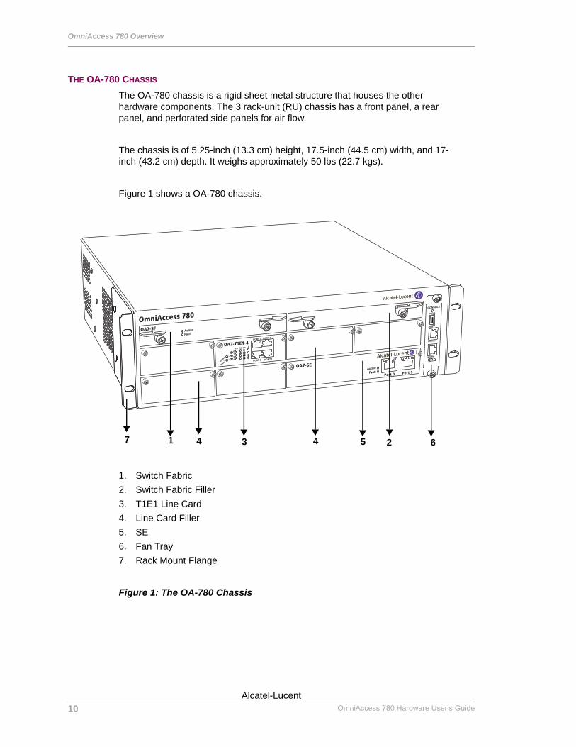
The OA-780 chassis is a rigid sheet metal structure that houses the other hardware components. The 3 rack-unit (RU) chassis has a front panel, a rear panel, and perforated side panels for air flow.
The chassis is of 5.25-inch (13.3 cm) height, 17.5-inch (44.5 cm) width, and 17-inch (43.2 cm) depth. It weighs approximately 50 lbs (22.7 kgs).
Figure 1 shows a OA-780 chassis.
1. Switch Fabric2. Switch Fabric Filler3. T1E1 Line Card4. Line Card Filler5. SE6. Fan Tray7. Rack Mount Flange
Figure 1: The OA-780 Chassis
OmniAccess 780
OA7-SF
OA7-T1E1-4
OA7-SE
Port 0 Port 1
7 41 24 5 63
10
Beta BetaOmniAccess 780 Hardware User’s Guide
Alcatel-Lucent
Hardware Overview
Except on the first page, right running head: Heading1 or Heading1NewPage text (automatic)
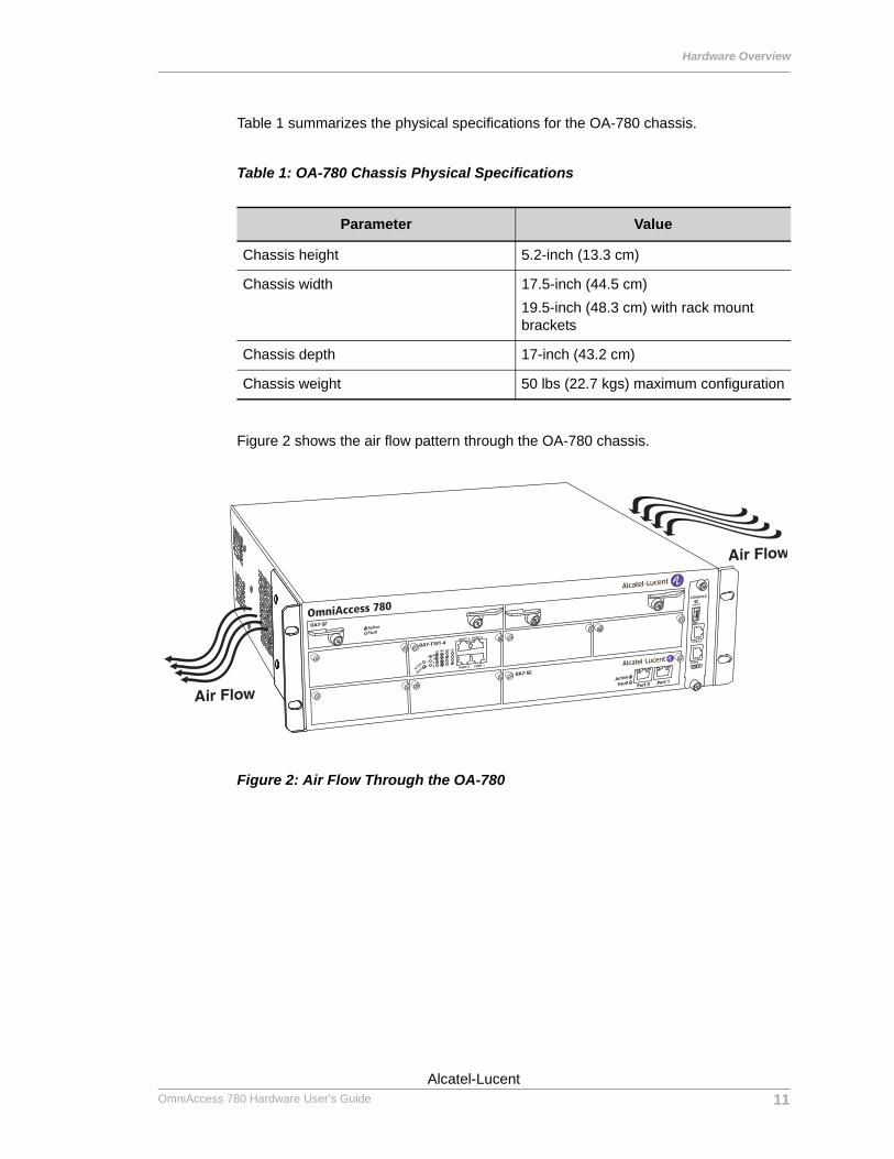
Table 1 summarizes the physical specifications for the OA-780 chassis.
Table 1: OA-780 Chassis Physical Specifications
Figure 2 shows the air flow pattern through the OA-780 chassis.
Figure 2: Air Flow Through the OA-780
Parameter Value
Chassis height 5.2-inch (13.3 cm)
Chassis width 17.5-inch (44.5 cm)19.5-inch (48.3 cm) with rack mount brackets
Chassis depth 17-inch (43.2 cm)
Chassis weight 50 lbs (22.7 kgs) maximum configuration
OmniAccess 780OA7-SF
OA7-T1E1-4
OA7-SE
Port 0 Port 1
11Alcatel-Lucent
Beta BetaOmniAccess 780 Hardware User’s Guide
OmniAccess 780 Overview
Left running head: Chapter name (automatic)
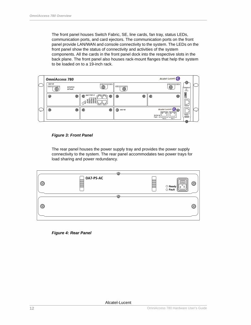
The front panel houses Switch Fabric, SE, line cards, fan tray, status LEDs, communication ports, and card ejectors. The communication ports on the front panel provide LAN/WAN and console connectivity to the system. The LEDs on the front panel show the status of connectivity and activities of the system components. All the cards in the front panel dock into the respective slots in the back plane. The front panel also houses rack-mount flanges that help the system to be loaded on to a 19-inch rack.
Figure 3: Front Panel
The rear panel houses the power supply tray and provides the power supply connectivity to the system. The rear panel accommodates two power trays for load sharing and power redundancy.
Figure 4: Rear Panel
OmniAccess 780OA7-SF
OA7-T1E1-4
OA7-SE
OA7-PS-AC
12
Beta BetaOmniAccess 780 Hardware User’s Guide
Alcatel-Lucent
Hardware Overview
Except on the first page, right running head: Heading1 or Heading1NewPage text (automatic)
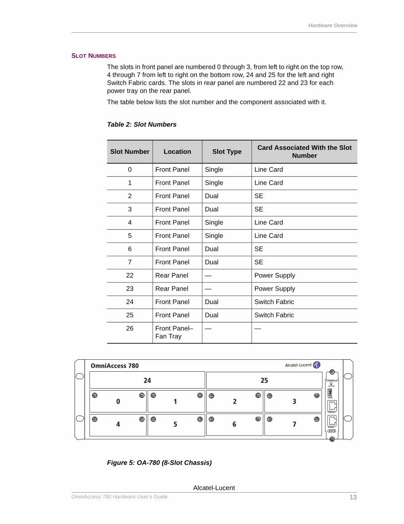
SLOT NUMBERS
The slots in front panel are numbered 0 through 3, from left to right on the top row, 4 through 7 from left to right on the bottom row, 24 and 25 for the left and right Switch Fabric cards. The slots in rear panel are numbered 22 and 23 for each power tray on the rear panel.
The table below lists the slot number and the component associated with it.
Table 2: Slot Numbers
Figure 5: OA-780 (8-Slot Chassis)
Slot Number Location Slot Type Card Associated With the Slot Number
0 Front Panel Single Line Card
1 Front Panel Single Line Card
2 Front Panel Dual SE
3 Front Panel Dual SE
4 Front Panel Single Line Card
5 Front Panel Single Line Card
6 Front Panel Dual SE
7 Front Panel Dual SE
22 Rear Panel — Power Supply
23 Rear Panel — Power Supply
24 Front Panel Dual Switch Fabric
25 Front Panel Dual Switch Fabric
26 Front Panel–Fan Tray
— —
0 1 2 3
7654
24 25
OmniAccess 780
13Alcatel-Lucent
Beta BetaOmniAccess 780 Hardware User’s Guide
OmniAccess 780 Overview
Left running head: Chapter name (automatic)
LED INFORMATION
The following table shows the state of main LEDs after startup.
Table 3: LED Status Table
LED Status Description
SE LEDs
Active Off Power up status. This is the default display when the system is first powered on and before the software is loaded.
Green SE card is active.
Yellow Indicates transient conditions (e.g., booting).
Switch Fabric LEDs
Active Off Power up status. This is the default display when the system is first powered on and before the software is loaded.
Green Switch Fabric is active.
Fan Tray Status LED (Tricolor LED)
Off Power up status. This is the default display when the system is first powered on and before the software is loaded.
Red Some component of the system is not being managed by the Chassis Manager, or the Chassis Manager has exited, or the system was “reloaded”, or the Chassis Manager has not yet restarted.
Amber Indicates transient conditions (e.g., booting).
Green Bootup completed, and system is ready to use.
Fan Tray LEDs (3 Uni-color Port LEDs) representing USB, Console, and Modem ports
Off System is not working.
Console LED Green Console is accessible.
14
Beta BetaOmniAccess 780 Hardware User’s Guide
Alcatel-Lucent
Hardware Overview
Except on the first page, right running head: Heading1 or Heading1NewPage text (automatic)
CABLE CONNECTION TABLE
The following table summarizes the cable connections for the OA-780.
Table 4: Cable Connections Table
Port or Module Port Type Connect To
Power Tray IEC 60320 (320) C-14 Power Inlet Main power supply
Ethernet RJ-45 Ethernet hub or switch
T1E1 RJ-45 T1E1 network
Console RJ-45 PC or VT100
Modem RJ-11 Telephone Line
Serial 68 pin VHDCI Connector V.35/X.21 modem
15Alcatel-Lucent
Beta BetaOmniAccess 780 Hardware User’s Guide
OmniAccess 780 Overview
Left running head: Chapter name (automatic)
USER MODULES
This section provides description about the modules/components that can be installed.
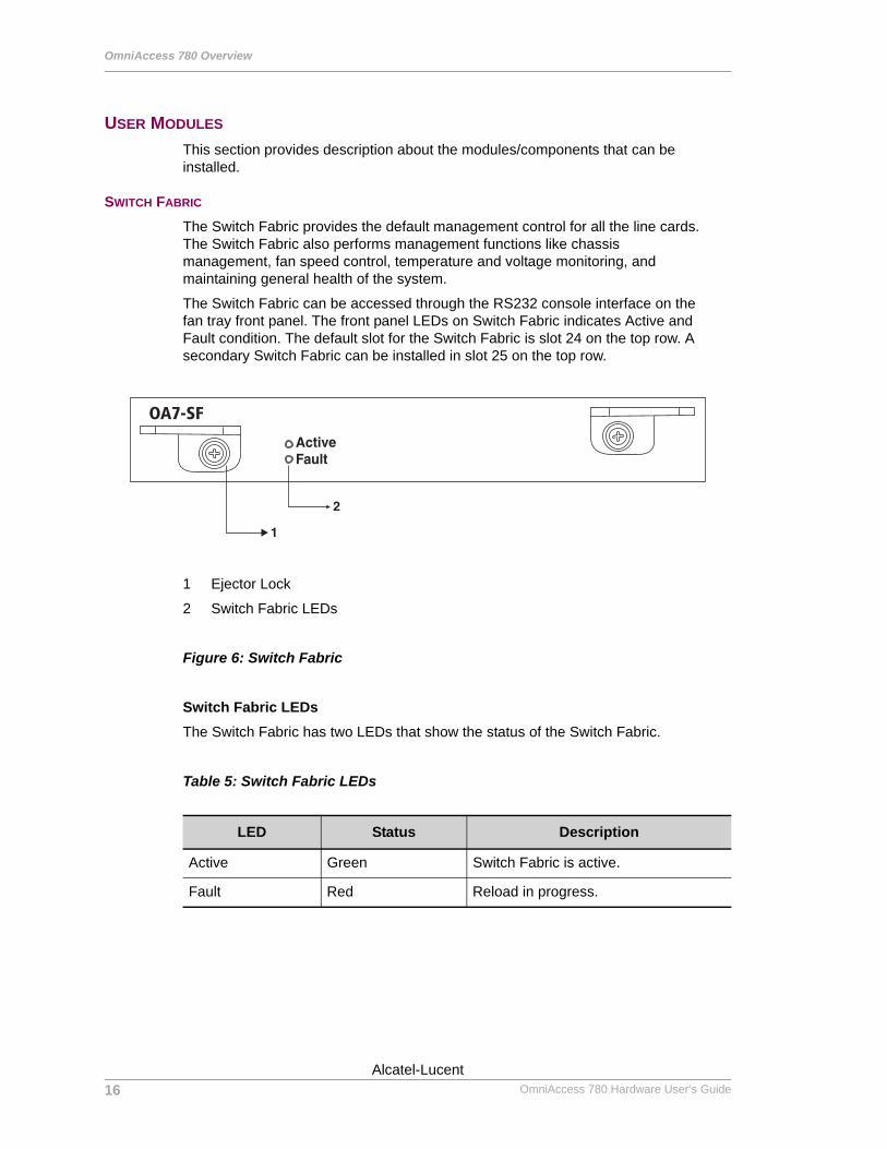
SWITCH FABRIC
The Switch Fabric provides the default management control for all the line cards. The Switch Fabric also performs management functions like chassis management, fan speed control, temperature and voltage monitoring, and maintaining general health of the system.
The Switch Fabric can be accessed through the RS232 console interface on the fan tray front panel. The front panel LEDs on Switch Fabric indicates Active and Fault condition. The default slot for the Switch Fabric is slot 24 on the top row. A secondary Switch Fabric can be installed in slot 25 on the top row.
1 Ejector Lock
2 Switch Fabric LEDs
Figure 6: Switch Fabric
Switch Fabric LEDsThe Switch Fabric has two LEDs that show the status of the Switch Fabric.
Table 5: Switch Fabric LEDs
LED Status Description
Active Green Switch Fabric is active.
Fault Red Reload in progress.
OA7-SF
16
Beta BetaOmniAccess 780 Hardware User’s Guide
Alcatel-Lucent
Hardware Overview
Except on the first page, right running head: Heading1 or Heading1NewPage text (automatic)
LINE CARDS
All the line cards can be mounted on a single slot except SE that require two slots. Next generation SE line cards may occupy a single slot only. An overview of the line cards is given below.
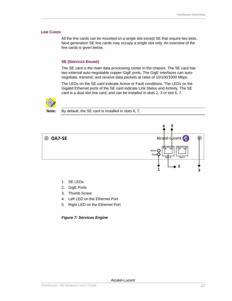
SE (SERVICES ENGINE)The SE card is the main data processing center in the chassis. The SE card has two external auto-negotiable copper GigE ports. The GigE interfaces can auto-negotiate, transmit, and receive data packets at rates of 10/100/1000 Mbps.
The LEDs on the SE card indicate Active or Fault conditions. The LEDs on the Gigabit Ethernet ports of the SE card indicate Link Status and Activity. The SE card is a dual slot line card, and can be installed in slots 2, 3 or slot 6, 7.
Note: By default, the SE card is installed in slots 6, 7.
1. SE LEDs2. GigE Ports3. Thumb Screw4. Left LED on the Ethernet Port5. Right LED on the Ethernet Port
Figure 7: Services Engine
OA7-SE
4 5
32
1
17Alcatel-Lucent
Beta BetaOmniAccess 780 Hardware User’s Guide
OmniAccess 780 Overview
Left running head: Chapter name (automatic)
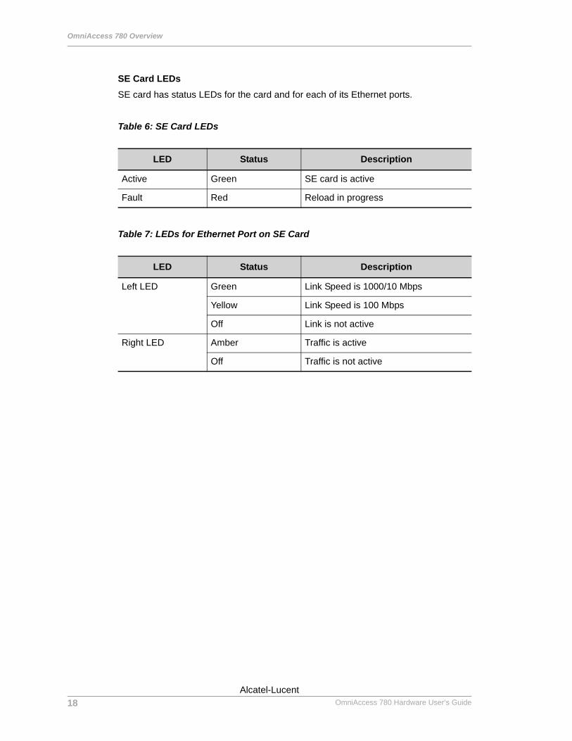
SE Card LEDsSE card has status LEDs for the card and for each of its Ethernet ports.
Table 6: SE Card LEDs
Table 7: LEDs for Ethernet Port on SE Card
LED Status Description
Active Green SE card is active
Fault Red Reload in progress
LED Status Description
Left LED Green Link Speed is 1000/10 Mbps
Yellow Link Speed is 100 Mbps
Off Link is not active
Right LED Amber Traffic is active
Off Traffic is not active
18
Beta BetaOmniAccess 780 Hardware User’s Guide
Alcatel-Lucent
Hardware Overview
Except on the first page, right running head: Heading1 or Heading1NewPage text (automatic)
4-PORT T1E1 LINE CARD
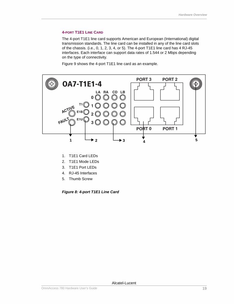
The 4-port T1E1 line card supports American and European (International) digital transmission standards. The line card can be installed in any of the line card slots of the chassis. (i.e., 0, 1, 2, 3, 4, or 5). The 4-port T1E1 line card has 4 RJ-45 interfaces. Each interface can support data rates of 1.544 or 2 Mbps depending on the type of connectivity.
Figure 9 shows the 4-port T1E1 line card as an example.
1. T1E1 Card LEDs2. T1E1 Mode LEDs3. T1E1 Port LEDs4. RJ-45 Interfaces5. Thumb Screw
Figure 8: 4-port T1E1 Line Card
OA7-T1E1-4
1 2 3 4 5
19Alcatel-Lucent
Beta BetaOmniAccess 780 Hardware User’s Guide
OmniAccess 780 Overview
Left running head: Chapter name (automatic)
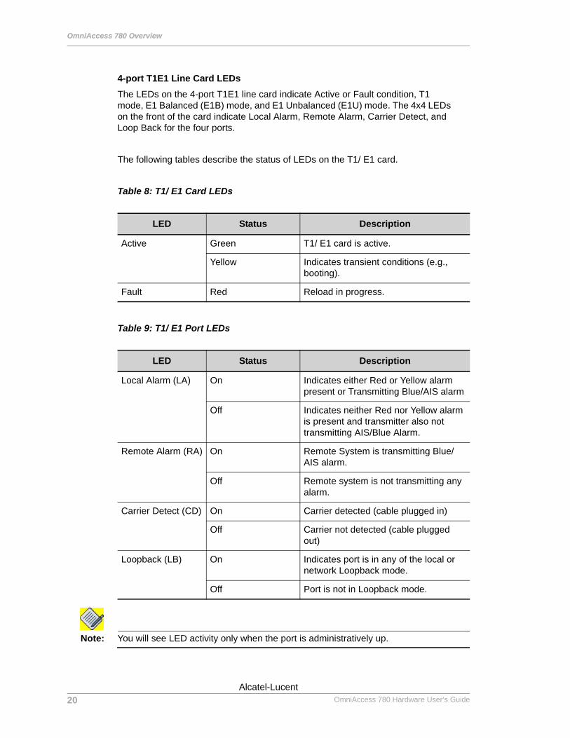
4-port T1E1 Line Card LEDsThe LEDs on the 4-port T1E1 line card indicate Active or Fault condition, T1 mode, E1 Balanced (E1B) mode, and E1 Unbalanced (E1U) mode. The 4x4 LEDs on the front of the card indicate Local Alarm, Remote Alarm, Carrier Detect, and Loop Back for the four ports.
The following tables describe the status of LEDs on the T1/ E1 card.
Table 8: T1/ E1 Card LEDs
Table 9: T1/ E1 Port LEDs
Note: You will see LED activity only when the port is administratively up.
LED Status Description
Active Green T1/ E1 card is active.
Yellow Indicates transient conditions (e.g., booting).
Fault Red Reload in progress.
LED Status Description
Local Alarm (LA) On Indicates either Red or Yellow alarm present or Transmitting Blue/AIS alarm
Off Indicates neither Red nor Yellow alarm is present and transmitter also not transmitting AIS/Blue Alarm.
Remote Alarm (RA) On Remote System is transmitting Blue/AIS alarm.
Off Remote system is not transmitting any alarm.
Carrier Detect (CD) On Carrier detected (cable plugged in)
Off Carrier not detected (cable plugged out)
Loopback (LB) On Indicates port is in any of the local or network Loopback mode.
Off Port is not in Loopback mode.
20
Beta BetaOmniAccess 780 Hardware User’s Guide
Alcatel-Lucent
Hardware Overview
Except on the first page, right running head: Heading1 or Heading1NewPage text (automatic)
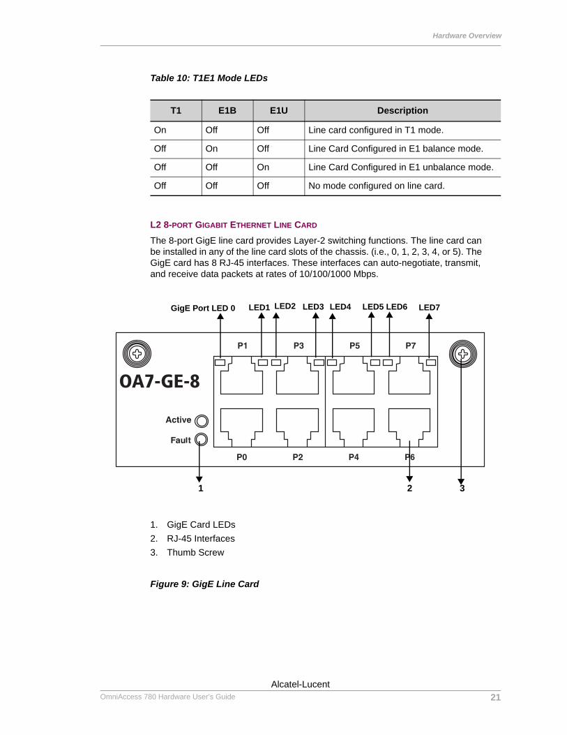
Table 10: T1E1 Mode LEDs
L2 8-PORT GIGABIT ETHERNET LINE CARD
The 8-port GigE line card provides Layer-2 switching functions. The line card can be installed in any of the line card slots of the chassis. (i.e., 0, 1, 2, 3, 4, or 5). The GigE card has 8 RJ-45 interfaces. These interfaces can auto-negotiate, transmit, and receive data packets at rates of 10/100/1000 Mbps.
1. GigE Card LEDs2. RJ-45 Interfaces3. Thumb Screw
Figure 9: GigE Line Card
T1 E1B E1U Description
On Off Off Line card configured in T1 mode.
Off On Off Line Card Configured in E1 balance mode.
Off Off On Line Card Configured in E1 unbalance mode.
Off Off Off No mode configured on line card.
OA7-GE-8
2
GigE Port LED 0 LED1 LED2
3
LED4LED3 LED5 LED6 LED7
1
21Alcatel-Lucent
Beta BetaOmniAccess 780 Hardware User’s Guide
OmniAccess 780 Overview
Left running head: Chapter name (automatic)
GigE Line Card LEDsThe LEDs on the GigE line card indicate Active or Fault conditions. The LEDs on each of the card’s ports indicate Link Status and Activity.
The following tables describe the status of LEDs on the GigE card.
Table 11: GigE Card LEDs
Table 12: LEDs for each Port on GigE Card
LED Status Description
Active Green GigE card is active.
Yellow Indicates transient conditions (e.g., booting).
Fault Red Reload in progress.
LED Status Description
LED 0 Off Port 0 link is not active.
Solid Green Port 0 link is active.
Blinking Green Port 0 link and traffic is active.
LED 1 Off Port 1 link is not active.
Solid Green Port 1 link is active.
Blinking Green Port 1 link and traffic is active.
LED 2 Off Port 2 link is not active.
Solid Green Port 2 link is active.
Blinking Green Port 2 link and traffic is active.
LED 3 Off Port 3 link is not active.
Solid Green Port 3 link is active.
Blinking Green Port 3 link and traffic is active.
LED 4 Off Port 4 link is not active.
Solid Green Port 4 link is active.
Blinking Green Port 4 link and traffic is active.
22
Beta BetaOmniAccess 780 Hardware User’s Guide
Alcatel-Lucent
Hardware Overview
Except on the first page, right running head: Heading1 or Heading1NewPage text (automatic)
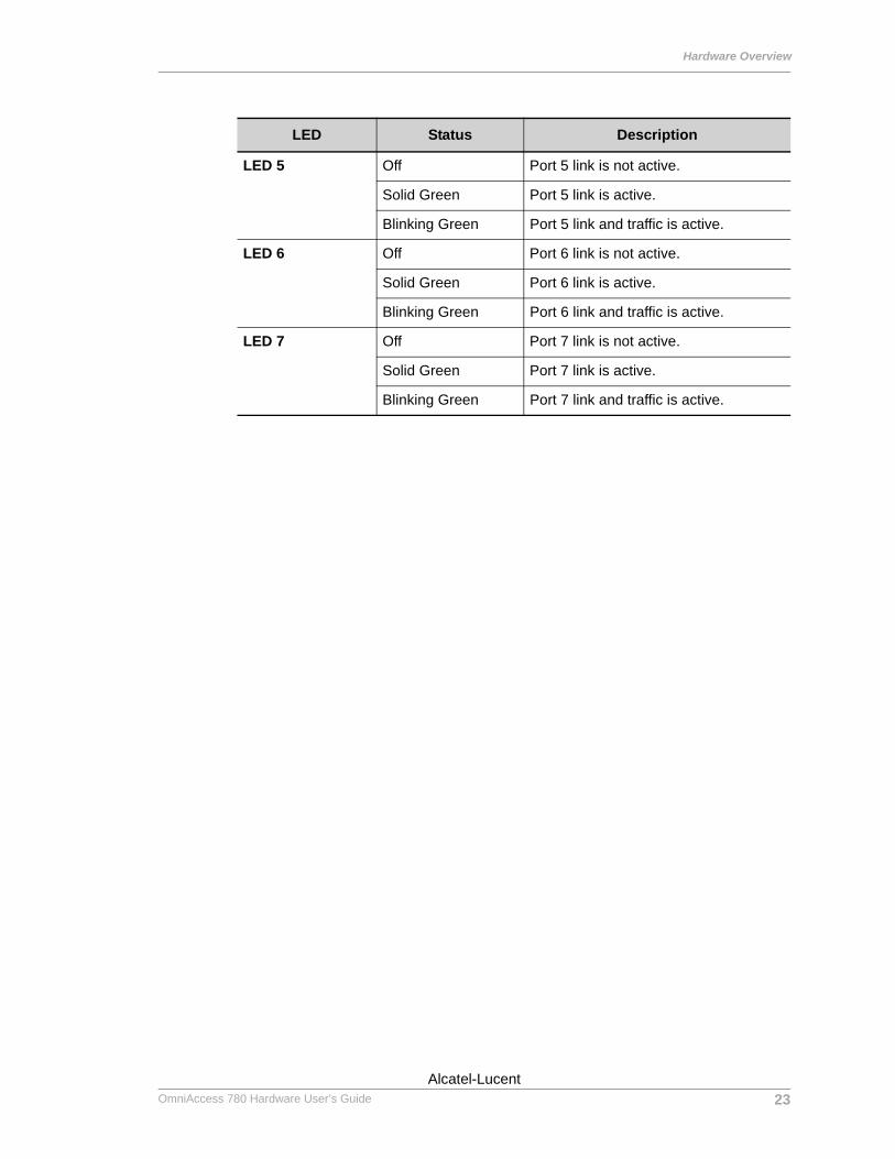
LED 5 Off Port 5 link is not active.
Solid Green Port 5 link is active.
Blinking Green Port 5 link and traffic is active.
LED 6 Off Port 6 link is not active.
Solid Green Port 6 link is active.
Blinking Green Port 6 link and traffic is active.
LED 7 Off Port 7 link is not active.
Solid Green Port 7 link is active.
Blinking Green Port 7 link and traffic is active.
LED Status Description
23Alcatel-Lucent
Beta BetaOmniAccess 780 Hardware User’s Guide
OmniAccess 780 Overview
Left running head: Chapter name (automatic)
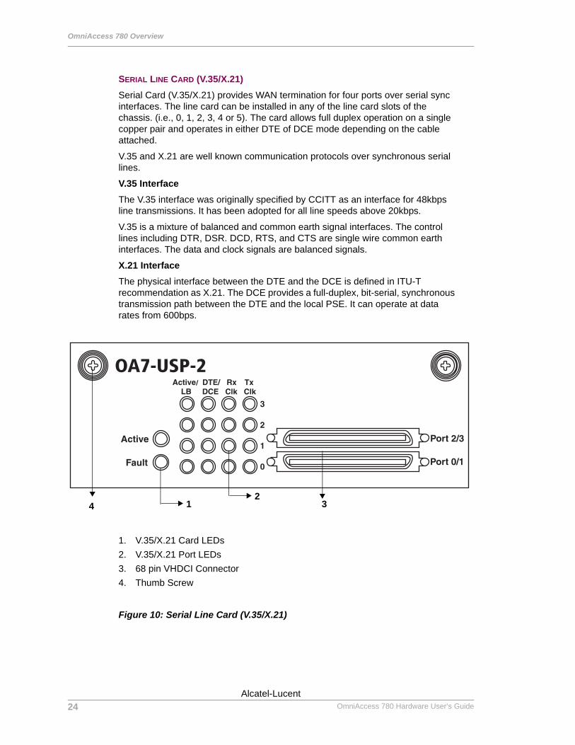
SERIAL LINE CARD (V.35/X.21)Serial Card (V.35/X.21) provides WAN termination for four ports over serial sync interfaces. The line card can be installed in any of the line card slots of the chassis. (i.e., 0, 1, 2, 3, 4 or 5). The card allows full duplex operation on a single copper pair and operates in either DTE of DCE mode depending on the cable attached.
V.35 and X.21 are well known communication protocols over synchronous serial lines.
V.35 InterfaceThe V.35 interface was originally specified by CCITT as an interface for 48kbps line transmissions. It has been adopted for all line speeds above 20kbps.
V.35 is a mixture of balanced and common earth signal interfaces. The control lines including DTR, DSR. DCD, RTS, and CTS are single wire common earth interfaces. The data and clock signals are balanced signals.
X.21 InterfaceThe physical interface between the DTE and the DCE is defined in ITU-T recommendation as X.21. The DCE provides a full-duplex, bit-serial, synchronous transmission path between the DTE and the local PSE. It can operate at data rates from 600bps.
1. V.35/X.21 Card LEDs2. V.35/X.21 Port LEDs3. 68 pin VHDCI Connector4. Thumb Screw
Figure 10: Serial Line Card (V.35/X.21)
OA7-USP-2
4 312
24
Beta BetaOmniAccess 780 Hardware User’s Guide
Alcatel-Lucent
Hardware Overview
Except on the first page, right running head: Heading1 or Heading1NewPage text (automatic)
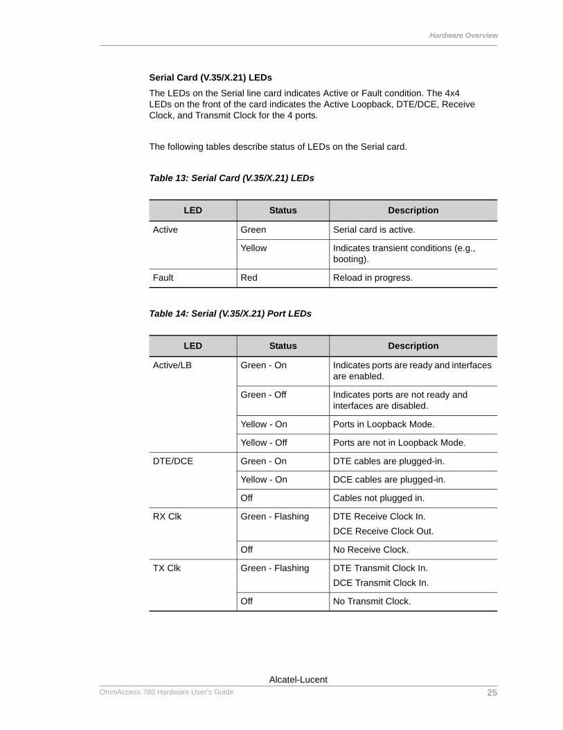
Serial Card (V.35/X.21) LEDsThe LEDs on the Serial line card indicates Active or Fault condition. The 4x4 LEDs on the front of the card indicates the Active Loopback, DTE/DCE, Receive Clock, and Transmit Clock for the 4 ports.
The following tables describe status of LEDs on the Serial card.
Table 13: Serial Card (V.35/X.21) LEDs
Table 14: Serial (V.35/X.21) Port LEDs
LED Status Description
Active Green Serial card is active.
Yellow Indicates transient conditions (e.g., booting).
Fault Red Reload in progress.
LED Status Description
Active/LB Green - On Indicates ports are ready and interfaces are enabled.
Green - Off Indicates ports are not ready and interfaces are disabled.
Yellow - On Ports in Loopback Mode.
Yellow - Off Ports are not in Loopback Mode.
DTE/DCE Green - On DTE cables are plugged-in.
Yellow - On DCE cables are plugged-in.
Off Cables not plugged in.
RX Clk Green - Flashing DTE Receive Clock In.DCE Receive Clock Out.
Off No Receive Clock.
TX Clk Green - Flashing DTE Transmit Clock In.DCE Transmit Clock In.
Off No Transmit Clock.
25Alcatel-Lucent
Beta BetaOmniAccess 780 Hardware User’s Guide

Hardware Overview
Except on the first page, right running head: Heading1 or Heading1NewPage text (automatic)
Serial Card (V.35/X.21) Cable DetailsThe following table lists the part numbers for the Alcatel specific V.35/X.21 cables:
Table 15: Serial Card (V.35/X.21) Cable Part Numbers
Part No. Description
5100-0010-00 Cable ASSY V.35 DTE Cable with Male Connector (68 Pin SCSI Connector to V.35 DTE Male Connector)
5100-0011-00 Cable ASV.35 DCE Cable with Female Connector (68 Pin SCSI Connector to V.35 DCE Female Connector)
5100-0012-00 Cable ASSY X.21 DTE Cable with Male Connector (68 Pin SCSI Connector to X.21 DB15 Male Connector)
5100-0013-00 Cable AX.21 DCE Cable with Female Connector (68 Pin SCSI Connector to X.21 DB15 Female Connector)
26Alcatel-Lucent
Beta BetaOmniAccess 780 Hardware User’s Guide

OmniAccess 780 Overview
Left running head: Chapter name (automatic)
FAN TRAY
The Fan tray houses two adjustable speed fans for efficient chassis cooling. The Switch Fabric controls or adjusts the fan speed based on the chassis air temperature. In addition, the front panel of the fan tray has the following user interface ports, top through bottom.• USB Port - This port is used to connect an USB device for software upgrades,
configuration backup, and restoring data.• Console Port - The RS232 serial interface allows the user to access the system
console at 9600 baud. • Modem Port - A built-in V.90 modem allows the user to remotely access the
OA-780 through the RJ-11 port at speeds up to 56 Kbps.
Figure 11: Fan Tray
27
Beta BetaOmniAccess 780 Hardware User’s Guide
Alcatel-Lucent
Hardware Overview
Except on the first page, right running head: Heading1 or Heading1NewPage text (automatic)
1 Thumb Screw
2 Status LED
3 USB Port
4 Console Port
5 Modem Port
6 Port LEDs
Figure 12: Ports on Fan Tray
28Alcatel-Lucent
Beta BetaOmniAccess 780 Hardware User’s Guide
OmniAccess 780 Overview
Left running head: Chapter name (automatic)
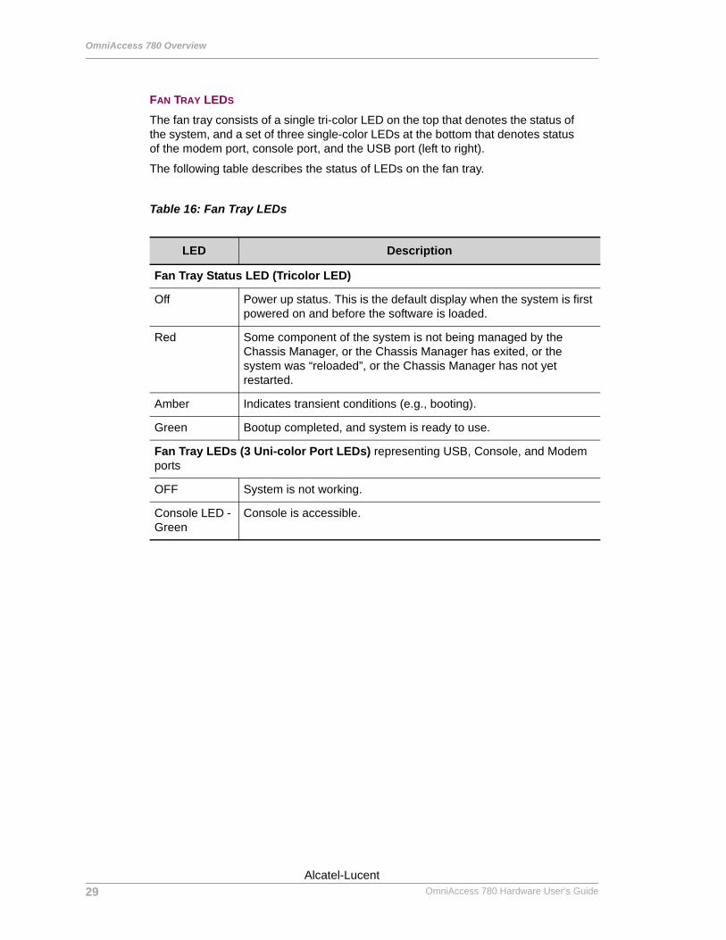
FAN TRAY LEDS
The fan tray consists of a single tri-color LED on the top that denotes the status of the system, and a set of three single-color LEDs at the bottom that denotes status of the modem port, console port, and the USB port (left to right).
The following table describes the status of LEDs on the fan tray.
Table 16: Fan Tray LEDs
LED Description
Fan Tray Status LED (Tricolor LED)
Off Power up status. This is the default display when the system is first powered on and before the software is loaded.
Red Some component of the system is not being managed by the Chassis Manager, or the Chassis Manager has exited, or the system was “reloaded”, or the Chassis Manager has not yet restarted.
Amber Indicates transient conditions (e.g., booting).
Green Bootup completed, and system is ready to use.
Fan Tray LEDs (3 Uni-color Port LEDs) representing USB, Console, and Modem ports
OFF System is not working.
Console LED - Green
Console is accessible.
29
Beta BetaOmniAccess 780 Hardware User’s Guide
Alcatel-Lucent
Hardware Overview
Except on the first page, right running head: Heading1 or Heading1NewPage text (automatic)
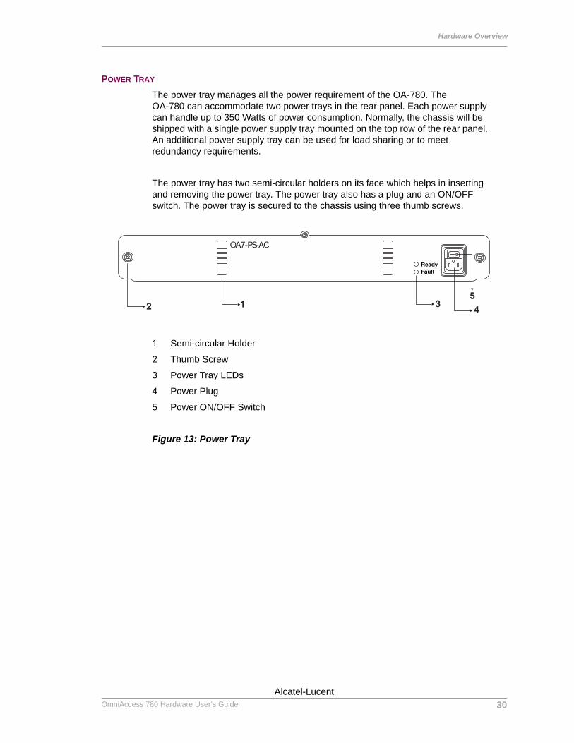
POWER TRAY
The power tray manages all the power requirement of the OA-780. The OA-780 can accommodate two power trays in the rear panel. Each power supply can handle up to 350 Watts of power consumption. Normally, the chassis will be shipped with a single power supply tray mounted on the top row of the rear panel. An additional power supply tray can be used for load sharing or to meet redundancy requirements.
The power tray has two semi-circular holders on its face which helps in inserting and removing the power tray. The power tray also has a plug and an ON/OFF switch. The power tray is secured to the chassis using three thumb screws.
1 Semi-circular Holder
2 Thumb Screw
3 Power Tray LEDs
4 Power Plug
5 Power ON/OFF Switch
Figure 13: Power Tray
OA7-PS-AC
30Alcatel-Lucent
Beta BetaOmniAccess 780 Hardware User’s Guide
OmniAccess 780 Overview
Left running head: Chapter name (automatic)
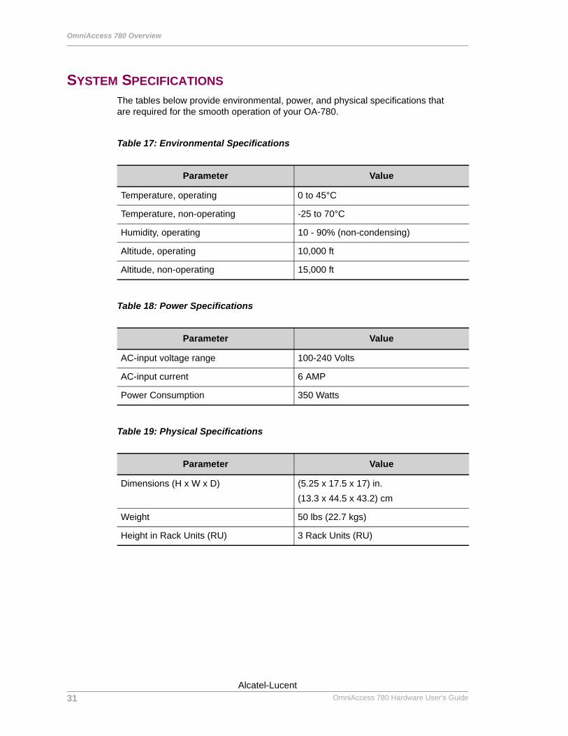
SYSTEM SPECIFICATIONSThe tables below provide environmental, power, and physical specifications that are required for the smooth operation of your OA-780.
Table 17: Environmental Specifications
Table 18: Power Specifications
Table 19: Physical Specifications
Parameter Value
Temperature, operating 0 to 45°C
Temperature, non-operating -25 to 70°C
Humidity, operating 10 - 90% (non-condensing)
Altitude, operating 10,000 ft
Altitude, non-operating 15,000 ft
Parameter Value
AC-input voltage range 100-240 Volts
AC-input current 6 AMP
Power Consumption 350 Watts
Parameter Value
Dimensions (H x W x D) (5.25 x 17.5 x 17) in.(13.3 x 44.5 x 43.2) cm
Weight 50 lbs (22.7 kgs)
Height in Rack Units (RU) 3 Rack Units (RU)
31
Beta BetaOmniAccess 780 Hardware User’s Guide
Alcatel-Lucent
System Specifications
Except on the first page, right running head: Heading1 or Heading1NewPage text (automatic)
VALID SYSTEM CONFIGURATION
The table below lists the minimum and maximum number of components that can be used in the OA-780.
Table 20: Valid System Configuration
Services Engine
Switch Fabric Line Card Fan Tray Power
Tray
Minimum Configuration
1 1 0 - 4 1 1
Maximum Configuration
1 1 0 - 6 1 2
32Alcatel-Lucent
Beta BetaOmniAccess 780 Hardware User’s Guide
For final production, import color definitions from\\daldoc01\docteam\templates\framemaker\book-template\color-defs\ production-colors.fm. Do not import other template elements such as page layout.
To return to the draft version, import color def’ns from draft-colors.fm.To switch to the beta version, import color def’ns from beta-colors.fm
Optional footer: Manual title (to set, redefine ManualTitlevariable)
CHAPTER 3
agination: umeric & ntinuous
PNco
INSTALLING THE OMNIACCESS 780
This chapter guides you through the process of preparing your OmniAccess 780 (OA-780) for installation.
This chapter describes the equipment, tools, power, and site requirements for installing the OA-780. It contains the following sections:
• Preparing for Installation• Installation Checklist• Safety Measures• Site Requirement Guidelines• Power Supply Overview• General Installation• Rack-Mounting the OA-780• Installing User Modules
Before installing your OA-780, you should consider the power and cabling requirements that must be in place at your installation site. Other factors to consider would be the environmental conditions; the installation site must meet to maintain normal and safe operation of the system.
Beta BetaAlcatel-Lucent
33
Beta Betawith preceding section of book
OmniAccess 780 Hardware User’s Guide
Installing the OmniAccess 780
Left running head: Chapter name (automatic)
PREPARING FOR INSTALLATIONThe OA-780 is shipped with all the user modules installed in the chassis. However, optional modules may be shipped in a separate package from the main system.
If you wish to install the components on your own, you need to understand the proper installation procedure and the safety guidelines involved in performing the same.
If you notice any deviations in the contents received as against the order, contact Alcatel-Lucent Technical Support immediately.
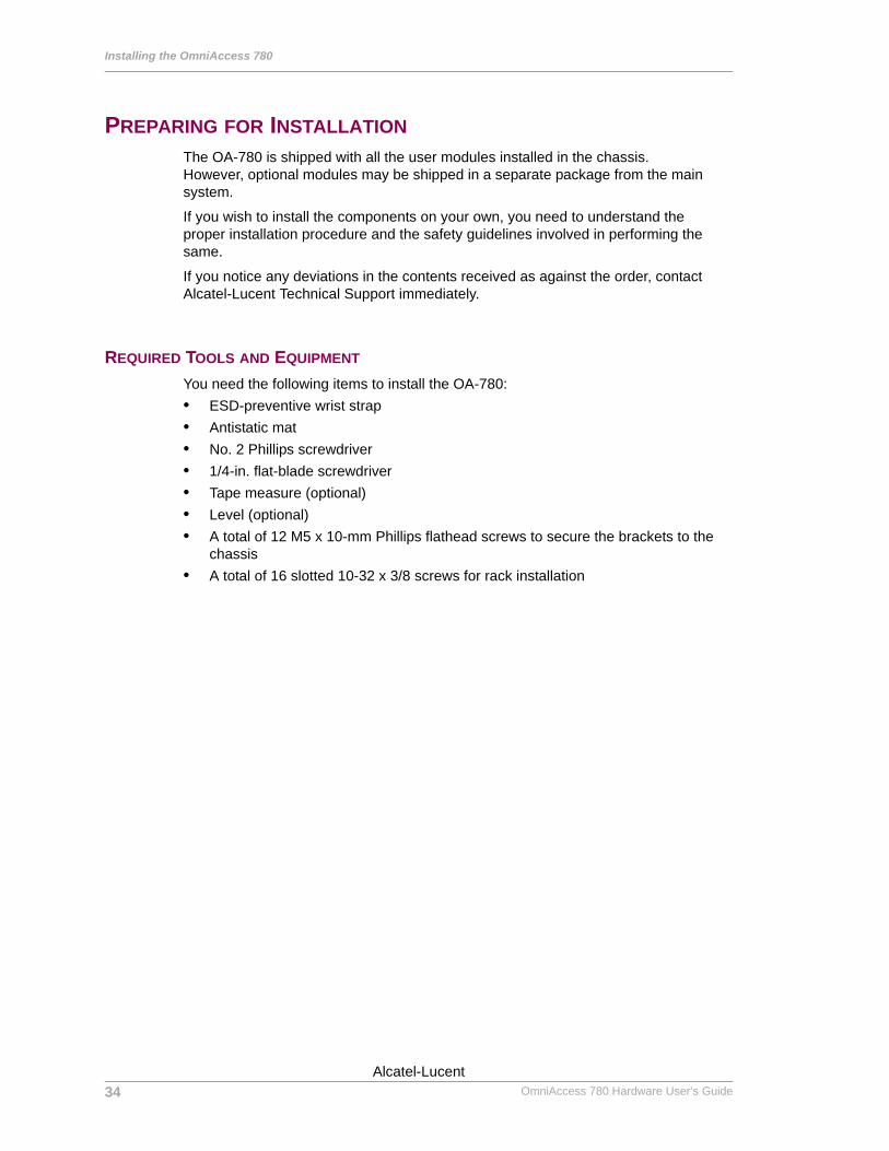
REQUIRED TOOLS AND EQUIPMENT
You need the following items to install the OA-780:• ESD-preventive wrist strap• Antistatic mat• No. 2 Phillips screwdriver• 1/4-in. flat-blade screwdriver• Tape measure (optional)• Level (optional)• A total of 12 M5 x 10-mm Phillips flathead screws to secure the brackets to the
chassis• A total of 16 slotted 10-32 x 3/8 screws for rack installation
34
Beta BetaOmniAccess 780 Hardware User’s Guide
Alcatel-Lucent
Installation Checklist
Except on the first page, right running head: Heading1 or Heading1NewPage text (automatic)
INSTALLATION CHECKLISTTo achieve a successful hardware installation, use the following checklist as a guideline before commencing with the installation.
Step 1: Unpack the system.
Open the carton the right way up, carefully remove contents in the package. Carefully remove the chassis from the carton.
Warning: Note that the OA-780 is heavy.
Note: Do not discard the shipping container. You will need the container if you move or ship the OA-780 in future.
Step 2: Verify the contents of the package.
Verify that the following contents are included in the shipping container (the accessories box might be separate):
• One OA-780, fully assembled• One or more accessories boxes (some or all may be shipped separately)
Note: The entire OA-780 documentation set is shipped with each system. These documents can also be downloaded from the Alcatel-Lucent Website.
Step 3: Verify the cards installed.
Verify that the line cards and Switch Fabrics installed in your OA-780 match the card types on the packing list.
Step 4: Have the tools to mount the chassis on the rack.
Keep tools, such as power screw-drivers, screws, cable guides/ties, etc., ready with you for mounting the chassis on the rack.
35Alcatel-Lucent
Beta BetaOmniAccess 780 Hardware User’s Guide
Installing the OmniAccess 780
Left running head: Chapter name (automatic)
SAFETY MEASURESThe sections below describe the safety instructions to be followed while using the OA-780.
Note: This equipment has been designed to the highest quality standards of materials, workmanship, and safety. Do not bypass any of the safety features of this equipment or operate this in an improper environment.
PREVENTING INJURY
Warning: Observe the following safety warnings to prevent accidental injury while working with the OA-780.
Follow the guidelines given below to avoid injury while working with the OA-780:• To avoid injury, be careful when lifting the chassis out of the shipping box.• Never attempt to rack mount the OA-780 chassis unaided. Ask an assistant to
help you hold the chassis.• Never operate the OA-780 with exposed power-supply units.• Never operate the OA-780 if the chassis becomes wet or the area where the
chassis is installed is wet.
EQUIPMENT GUIDELINES
The following guidelines will help to ensure your safety and protect the equipment. This list does not cover all potentially hazardous situations. However, Alcatel-Lucent advices you to observe caution while working with the system.
Warning: To avoid hazard from electrical shock and/or fire, adhere to safety practices listed in this section and identified within instructions of this document.
Warning: Do not turn ON/OFF the OA-780 without following the stated procedure.
Warning: Potentially hazardous voltage inside. Service should be performed only by qualified personal.
36
Beta BetaOmniAccess 780 Hardware User’s Guide
Alcatel-Lucent
Safety Measures
Except on the first page, right running head: Heading1 or Heading1NewPage text (automatic)
• The OA-780 is in compliance with national and local electrical codes. • Review the safety warnings, before installing, configuring, or maintaining the
OA-780.• Keep the system area clean and dust-free during and after installation.• Keep tools and rack shelf components away from walk areas.• Do not wear loose clothing, jewelry, or other items that could get caught in the
rack shelf. Fasten your tie or scarf and sleeves.• The equipment grounding should be in accordance with local and national
electrical codes.• Input and earth wiring must be provided at the installation site and protected in
accordance with local and national wiring regulations.• The OA-780 operates safely when it is used in accordance with its marked
electrical ratings and product usage instructions.
LIFTING SAFELY
A fully configured OA-780 weighs approximately 50 lbs or 22.68 kgs.
Whenever you lift any heavy object, follow the below guidelines:
Warning: Keep your back straight while lifting the OA-780 to prevent injury.
• Ensure that the system is powered OFF.• Disconnect all external cables before lifting or moving.• Do not attempt to lift by yourself; have someone assist you.• Ensure that your footing is solid, and balance the weight of the object between
your feet.• Lift the system slowly; never move suddenly or twist your body as you lift.• Lift the chassis from the bottom; grasp the underside of the chassis exterior with
both hands.
37Alcatel-Lucent
Beta BetaOmniAccess 780 Hardware User’s Guide
Installing the OmniAccess 780
Left running head: Chapter name (automatic)
SAFETY WITH ELECTRICITY
The power tray is designed to be removed and replaced while the system is operating without presenting an electrical hazard or damage to the system. Also the system has the feature of OIR. However, Alcatel-Lucent advices you to follow the guidelines given below as a measure of safety.
Warning: To avoid shock, do not open or attempt to service the unit or its associated power supply cards.
Caution: When connecting the power supply to the system and grounding, ensure that it presents no threat, harm, or non-compliance to operating staff or property. Verify that the unit is grounded properly and protected from voltage surges and static charges.
Caution: Observe all regional and national building and safety regulations.
Follow these basic guidelines when working with any electrical equipment:• Disconnect all power cables and external cables before installing or removing the
OA-780.• Do not work alone when potentially hazardous conditions exist.• Never assume that power has been disconnected from a circuit; always check.• Do not perform any action that creates a potential hazard to people or that makes
the equipment unsafe.• Never install/work with equipment that appears damaged.• Carefully examine your work area for possible hazards, such as moist floors,
ungrounded power extension cables, and missing safety grounds.
Warning: Explosive Device Proximity Warning—Do not operate the OA-780 near unshielded blasting caps or in an explosive environment unless the unit has been modified especially to be qualified for such use.
In addition, use these appropriate guidelines while working with any equipment that is disconnected from a power source, but still connected to the telephone wiring or other network cabling:• Never install telephone wiring during a lightning storm.• Never install telephone jacks in wet locations unless the jack is specifically
designed for wet locations.• Never touch un-insulated telephone wires or terminals unless the telephone line
has been disconnected at the network interface.• Use caution when installing or modifying telephone lines.
38
Beta BetaOmniAccess 780 Hardware User’s Guide
Alcatel-Lucent
Safety Measures
Except on the first page, right running head: Heading1 or Heading1NewPage text (automatic)
PREVENTING ELECTROSTATIC DISCHARGE DAMAGE
Electrostatic discharge (ESD) damage, which occurs when electronic cards or components are improperly handled, can result in complete or intermittent system failures. The line cards consist of printed circuit boards with Integrated Circuits (IC) and should be handled at edges or faceplate only.
Warning: Always tighten the captive tabs and levers on all the devices. These tabs and levers prevent accidental removal, provide proper grounding for the system, and help ensure that the cards are properly fitted in the shelf.
Follow the guidelines given below for preventing ESD damage:• Always use an ESD wrist strap or ankle strap and ensure that it makes good skin
contact and is properly grounded.• Do not touch the printed circuit board, and avoid contact between the printed
circuit board and your clothing.• Ensure the line cards are fully inserted in their respective chassis slots and the
thumb screws are tightened.
Warning: For safety, periodically check the resistance value of the antistatic strap. The measurement should be in 1 and 10 mega ohms range.
39Alcatel-Lucent
Beta BetaOmniAccess 780 Hardware User’s Guide
Installing the OmniAccess 780
Left running head: Chapter name (automatic)
SITE REQUIREMENT GUIDELINESThe guidelines in this section help you to maintain and protect your OA-780 and its components from potential damage from over-voltage, extreme temperature conditions, and other adverse conditions. To assure normal operation and avoid unnecessary maintenance, plan your site configuration and prepare your site before installing the OA-780.
Follow these general precautions when planning your equipment locations and connections:• Make sure the site maintains an ambient temperature between 15°C and 25°C,
and keep the area around the system clean and dust-free.• Ensure that the cooling vents are not blocked and there is adequate air flow due
to ample clearances around the OA-780. • Alcatel-Lucent recommends keeping the OA-780 off the floor and out of any area
that tends to collect dust.• Follow ESD prevention procedures to avoid damage to equipment. Damage from
static discharge can cause immediate or intermittent equipment failure.
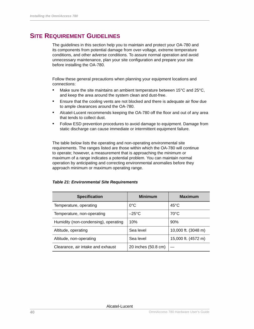
The table below lists the operating and non-operating environmental site requirements. The ranges listed are those within which the OA-780 will continue to operate; however, a measurement that is approaching the minimum or maximum of a range indicates a potential problem. You can maintain normal operation by anticipating and correcting environmental anomalies before they approach minimum or maximum operating range.
Table 21: Environmental Site Requirements
Specification Minimum Maximum
Temperature, operating 0°C 45°C
Temperature, non-operating –25°C 70°C
Humidity (non-condensing), operating 10% 90%
Altitude, operating Sea level 10,000 ft. (3048 m)
Altitude, non-operating Sea level 15,000 ft. (4572 m)
Clearance, air intake and exhaust 20 inches (50.8 cm) —
40
Beta BetaOmniAccess 780 Hardware User’s Guide
Alcatel-Lucent
Power Supply Overview
Except on the first page, right running head: Heading1 or Heading1NewPage text (automatic)
POWER SUPPLY OVERVIEWThe following sections provide power supply requirements for the OA-780.
POWER SUPPLY SPECIFICATIONS
The OA-780 requires 100/240V and 6A (RMS) @115V, 3A (RMS) @230V AC power. A fully loaded OA-780 consumes approximately 350 W of power.
For more details on power supply specifications, see ‘AC Power Specifications’.
The following section provides the procedure for connecting input power to yourOA-780.
Warning: Read the installation instructions before you connect the system to its power source.
41Alcatel-Lucent
Beta BetaOmniAccess 780 Hardware User’s Guide
Installing the OmniAccess 780
Left running head: Chapter name (automatic)
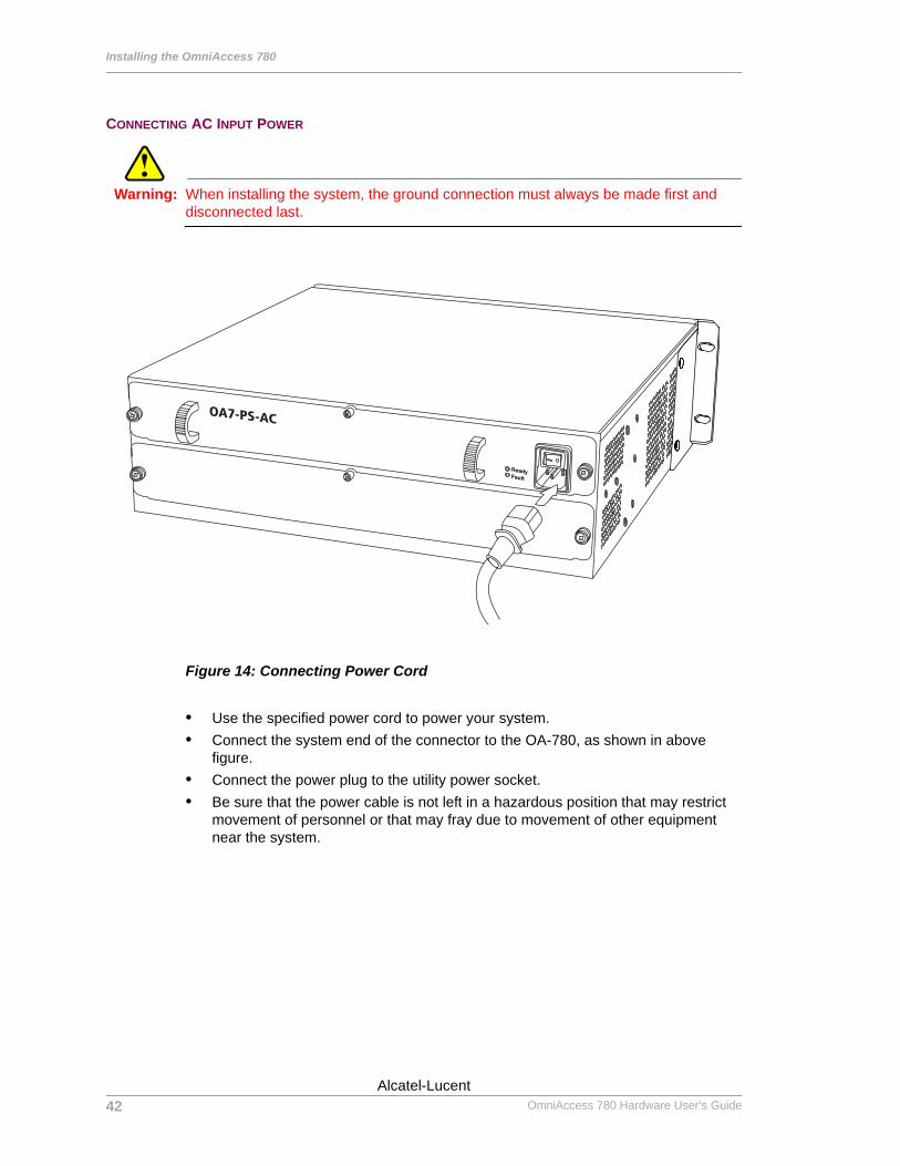
CONNECTING AC INPUT POWER
Warning: When installing the system, the ground connection must always be made first and disconnected last.
Figure 14: Connecting Power Cord
• Use the specified power cord to power your system.• Connect the system end of the connector to the OA-780, as shown in above
figure.• Connect the power plug to the utility power socket.• Be sure that the power cable is not left in a hazardous position that may restrict
movement of personnel or that may fray due to movement of other equipment near the system.
OA7-PS-AC
42
Beta BetaOmniAccess 780 Hardware User’s Guide
Alcatel-Lucent

Power Supply Overview
Except on the first page, right running head: Heading1 or Heading1NewPage text (automatic)
PLANT WIRING
The following are guidelines for setting up the plant wiring and cabling at your site. When planning the location of the new system, consider the distance limitations for signaling, electromagnetic interference (EMI), and connector compatibility, as described in the sections below:
INTERFERENCE CONSIDERATIONS
Interference can occur when wires are run for any significant distance in an electromagnetic field. To prevent damages caused by interference, do the following:• Ensure that there is no radio interference emanating from the plant wiring.• Ensure that there is no electrical hazard by conducting power surges through lines
and into equipment caused by EMI.• Use a high-quality twisted-pair cable with one ground conductor for each data
signal, when applicable.• Give special consideration to the effect of a lightning strike near the system
location. The electromagnetic pulse caused by lightning or other high-energy phenomena can destroy electronic devices.
DISTANCE LIMITATIONS AND INTERFACE SPECIFICATIONS
The size of your network and the distances between connections depend on signal type, and speed, and on transmission media. For example, standard coaxial cable has a greater channel capacity than twisted-pair cable.
When preparing your site for network connections to the OA-780, you should consider the following:• Type of cabling required (fiber, shielded twisted-pair, or unshielded twisted-pair)• Distance limitations• Cables needed for interface connections• Any additional interface equipment required, such as transceivers, hubs,
switches, modems, etc.
PRECAUTIONS TO BE TAKEN WHILE FIXING POWER CABLES
Follow these precautions and recommendations when planning power connections to the OA-780:• Check the power at your site before installation and periodically after installation
to ensure that you are receiving uninterrupted power. • Install a power conditioner if necessary.• Install proper grounding to avoid damage from lightning and power surges.
43Alcatel-Lucent
Beta BetaOmniAccess 780 Hardware User’s Guide
Installing the OmniAccess 780
Left running head: Chapter name (automatic)
GENERAL INSTALLATIONPlanning a proper location for the OA-780 and the layout of your equipment rack or wiring cabinet are essential for successful operation of the system. Equipment placed too close together or inadequately ventilated can cause system over-temperature conditions, which may lead to system failure. Follow the precautions given below to avoid problems during installation and ongoing operation.
The OA-780 should be installed as per guidelines provided in the “Site Requirement Guidelines” section of this document. Please follow the guidelines in choosing a suitable and safe location.
When installing the system, ensure that the location is clean and safe, and that you have considered the following:• The OA-780 requires at least 3 inches of clearance on the right and left sides.• The OA-780 should be installed off the floor. (Excessive dust inside the system
can cause over-temperature conditions and component failures.)• There must be approximately 20 inches (50.8 cm) of clearance in the front and
rear of the OA-780 for installing and replacing the system units, or accessing network cables or equipment.
• Line card and power supply filler panels are installed.• The OA-780 receives adequate ventilation (it should not be installed in an
enclosed cabinet where ventilation is inadequate).• Adequate ground (earth) connection for your OA-780 is provided.
44
Beta BetaOmniAccess 780 Hardware User’s Guide
Alcatel-Lucent
Rack-Mounting the OA-780
Except on the first page, right running head: Heading1 or Heading1NewPage text (automatic)
RACK-MOUNTING THE OA-780The OA-780 is mounted on a standard 19-inch equipment rack. To easily access the electrical cables while the system is installed in a rack, ensure that you have easy access to the front and rear of the system, and that there is about 20 inch clearance at the front and rear of the rack.
You can also mount the OA-780 on an equipment shelf provided that the rack dimensions allow you to secure the system to the shelf. However, Alcatel-Lucent recommends rack-mounting the OA-780.
To rack-mount the OA-780, consider the following guidelines:• Maximum recommended operating temperature
The maximum recommended operating temperature for the OA-780, indoor is 45° C. Determine a suitable operating environment based on this recommendation.
• Elevated operating ambient temperatureIf the unit is installed in a closed or multi-unit rack assembly, the operating temperature of the rack environment may be greater than the ambient temperature of the room. Keep this in mind when installing the OA-780.
• Reduced AirflowInstall the OA-780 shelf in the rack so that the amount of airflow required for safe operation of the equipment in not compromised.
• Mechanical LoadingMount the OA-780 in the rack so as to avoid a potentially hazardous condition due to uneven mechanical loading.
• Circuit OverloadingWhen you connect the OA-780 to the supply circuit, consider the effect that overloading of the circuits might have on over current protection and supply wiring.
• Reliable GroundingMaintain reliable grounding for the OA-780 and all rack-mounted equipment, giving particular attention to supply circuits.
Note: Alcatel-Lucent strongly recommends that you provide a ground connection to the OA-780.
45Alcatel-Lucent
Beta BetaOmniAccess 780 Hardware User’s Guide

Installing the OmniAccess 780
Left running head: Chapter name (automatic)
PARTS REQUIRED
The following tools and parts are required to rack-mount the OA-780:• AC power supply unit• One 6-gauge ground cable• Two hex nuts and M4 screws• Four 10-32 x 3/8-inch slotted screws• 3/8-inch nut driver• No. 2 Phillips screwdriver• 1/4-inch flat-blade screwdriver• Cable ties, if necessary
46
Beta BetaOmniAccess 780 Hardware User’s Guide
Alcatel-Lucent
Rack-Mounting the OA-780
Except on the first page, right running head: Heading1 or Heading1NewPage text (automatic)
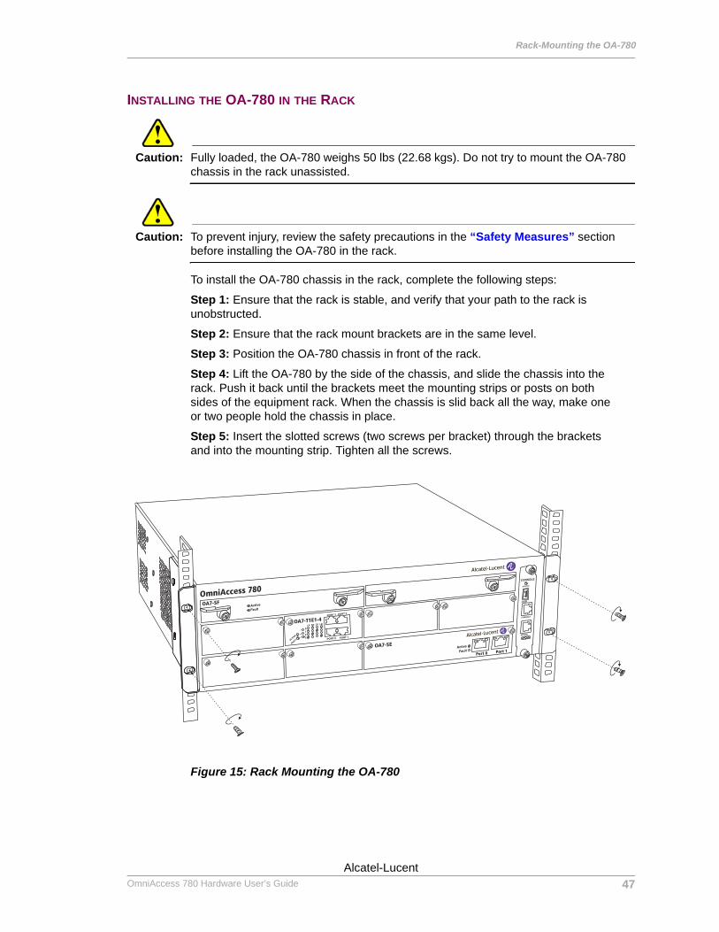
INSTALLING THE OA-780 IN THE RACK
Caution: Fully loaded, the OA-780 weighs 50 lbs (22.68 kgs). Do not try to mount the OA-780 chassis in the rack unassisted.
Caution: To prevent injury, review the safety precautions in the “Safety Measures” section before installing the OA-780 in the rack.
To install the OA-780 chassis in the rack, complete the following steps:
Step 1: Ensure that the rack is stable, and verify that your path to the rack is unobstructed.
Step 2: Ensure that the rack mount brackets are in the same level.
Step 3: Position the OA-780 chassis in front of the rack.
Step 4: Lift the OA-780 by the side of the chassis, and slide the chassis into the rack. Push it back until the brackets meet the mounting strips or posts on both sides of the equipment rack. When the chassis is slid back all the way, make one or two people hold the chassis in place.
Step 5: Insert the slotted screws (two screws per bracket) through the brackets and into the mounting strip. Tighten all the screws.
Figure 15: Rack Mounting the OA-780
OmniAccess 780
OA7-SF
OA7-T1E1-4
OA7-SE
Port 0 Port 1
47Alcatel-Lucent
Beta BetaOmniAccess 780 Hardware User’s Guide
Installing the OmniAccess 780
Left running head: Chapter name (automatic)
INSTALLING USER MODULESThe following sections describe the procedure to install user modules in your OA-780.
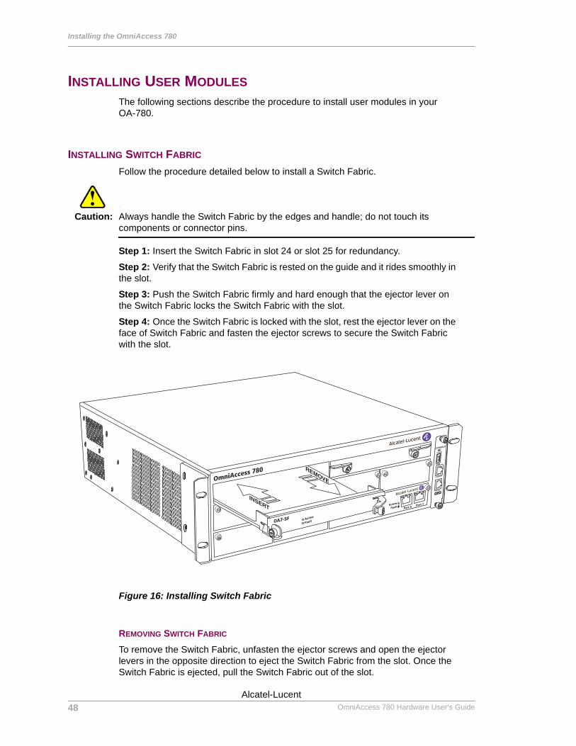
INSTALLING SWITCH FABRIC
Follow the procedure detailed below to install a Switch Fabric.
Caution: Always handle the Switch Fabric by the edges and handle; do not touch its components or connector pins.
Step 1: Insert the Switch Fabric in slot 24 or slot 25 for redundancy.
Step 2: Verify that the Switch Fabric is rested on the guide and it rides smoothly in the slot.
Step 3: Push the Switch Fabric firmly and hard enough that the ejector lever on the Switch Fabric locks the Switch Fabric with the slot.
Step 4: Once the Switch Fabric is locked with the slot, rest the ejector lever on the face of Switch Fabric and fasten the ejector screws to secure the Switch Fabric with the slot.
Figure 16: Installing Switch Fabric
REMOVING SWITCH FABRIC
To remove the Switch Fabric, unfasten the ejector screws and open the ejector levers in the opposite direction to eject the Switch Fabric from the slot. Once the Switch Fabric is ejected, pull the Switch Fabric out of the slot.
OmniAccess 780
OA7-SF
Port 0Port 1
48
Beta BetaOmniAccess 780 Hardware User’s Guide
Alcatel-Lucent
Installing User Modules
Except on the first page, right running head: Heading1 or Heading1NewPage text (automatic)
INSTALLING LINE CARDS
Follow the procedure detailed below to install the line cards.
Caution: Always handle the line cards by the edges and handle; do not touch the components or connector pins.
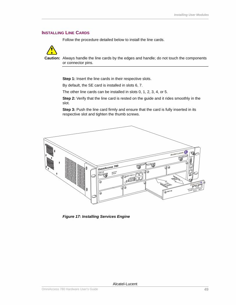
Step 1: Insert the line cards in their respective slots.
By default, the SE card is installed in slots 6, 7.
The other line cards can be installed in slots 0, 1, 2, 3, 4, or 5.
Step 2: Verify that the line card is rested on the guide and it rides smoothly in the slot.
Step 3: Push the line card firmly and ensure that the card is fully inserted in its respective slot and tighten the thumb screws.
Figure 17: Installing Services Engine
OmniAccess 780
OA7-SF
OA7-T1E1-4
OA7-SE Port 0Port 1
49Alcatel-Lucent
Beta BetaOmniAccess 780 Hardware User’s Guide
Installing the OmniAccess 780
Left running head: Chapter name (automatic)
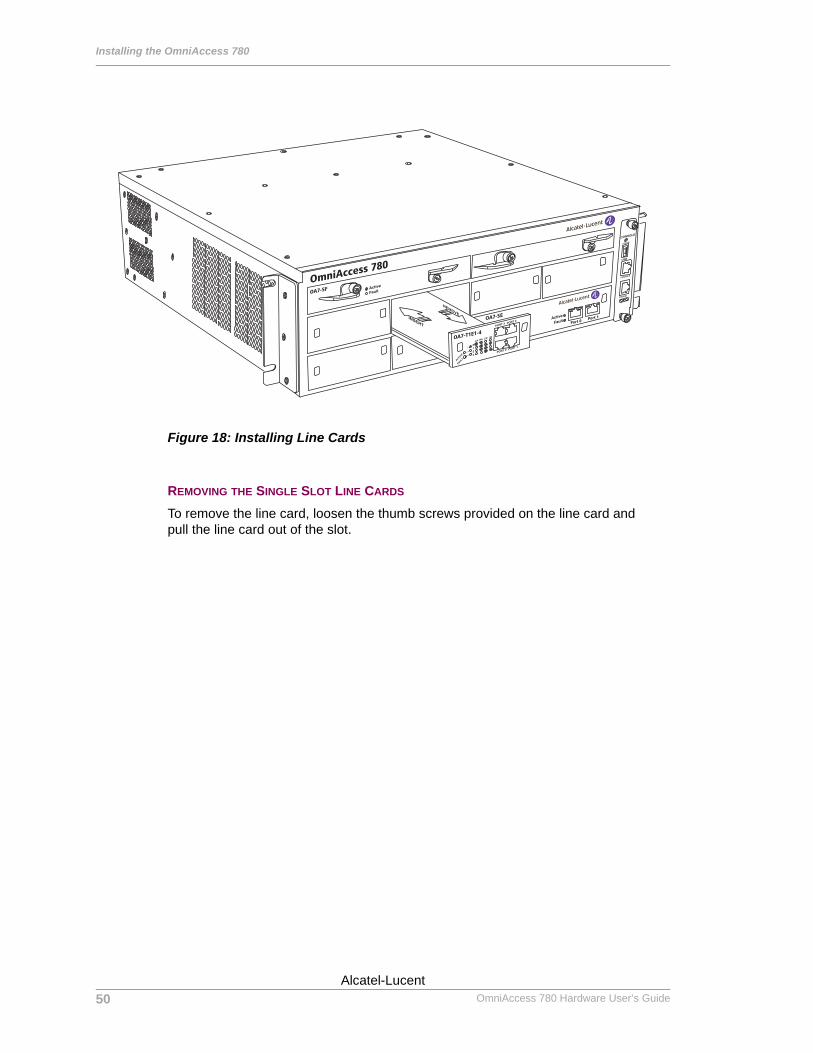
Figure 18: Installing Line Cards
REMOVING THE SINGLE SLOT LINE CARDS
To remove the line card, loosen the thumb screws provided on the line card and pull the line card out of the slot.
OmniAccess 780
OA7-SF
OA7-T1E1-4
OA7-SEPort 0
Port 1
50
Beta BetaOmniAccess 780 Hardware User’s Guide
Alcatel-Lucent
Installing User Modules
Except on the first page, right running head: Heading1 or Heading1NewPage text (automatic)
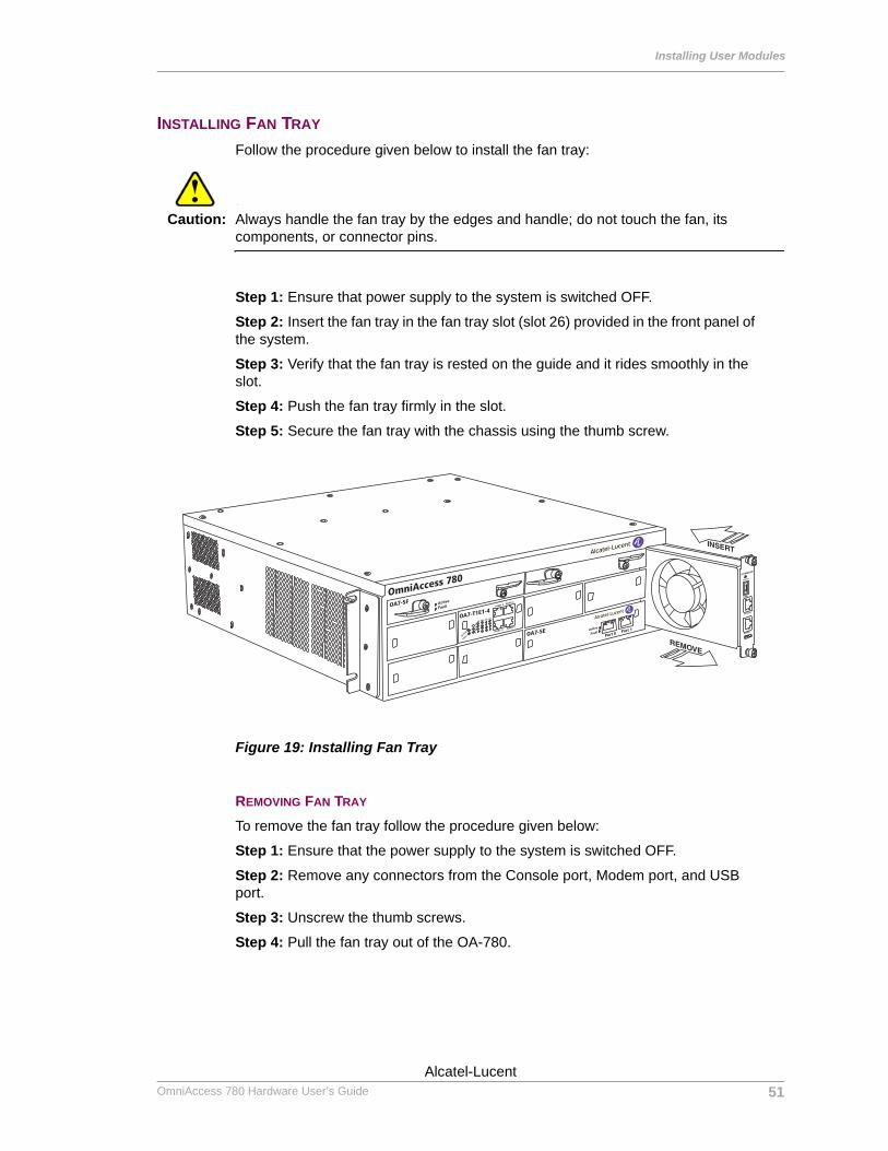
INSTALLING FAN TRAY
Follow the procedure given below to install the fan tray:
Caution: Always handle the fan tray by the edges and handle; do not touch the fan, its components, or connector pins.
Step 1: Ensure that power supply to the system is switched OFF.
Step 2: Insert the fan tray in the fan tray slot (slot 26) provided in the front panel of the system.
Step 3: Verify that the fan tray is rested on the guide and it rides smoothly in the slot.
Step 4: Push the fan tray firmly in the slot.
Step 5: Secure the fan tray with the chassis using the thumb screw.
Figure 19: Installing Fan Tray
REMOVING FAN TRAY
To remove the fan tray follow the procedure given below:
Step 1: Ensure that the power supply to the system is switched OFF.
Step 2: Remove any connectors from the Console port, Modem port, and USB port.
Step 3: Unscrew the thumb screws.
Step 4: Pull the fan tray out of the OA-780.
Port 0Port 1
OmniAccess 780
OA7-SF
OA7-T1E1-4
OA7-SE
51Alcatel-Lucent
Beta BetaOmniAccess 780 Hardware User’s Guide
Installing the OmniAccess 780
Left running head: Chapter name (automatic)
INSTALLING POWER TRAY
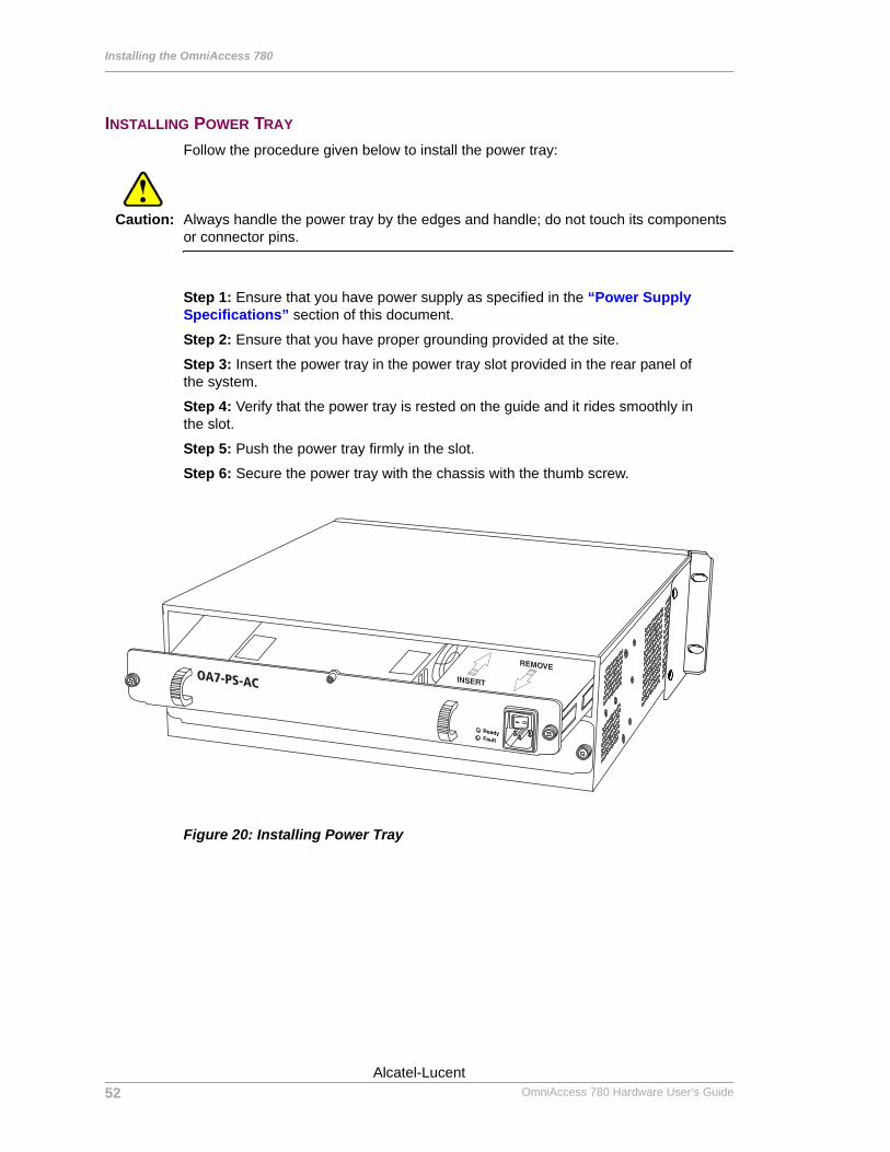
Follow the procedure given below to install the power tray:
Caution: Always handle the power tray by the edges and handle; do not touch its components or connector pins.
Step 1: Ensure that you have power supply as specified in the “Power Supply Specifications” section of this document.
Step 2: Ensure that you have proper grounding provided at the site.
Step 3: Insert the power tray in the power tray slot provided in the rear panel of the system.
Step 4: Verify that the power tray is rested on the guide and it rides smoothly in the slot.
Step 5: Push the power tray firmly in the slot.
Step 6: Secure the power tray with the chassis with the thumb screw.
Figure 20: Installing Power Tray
OA7-PS-AC
52
Beta BetaOmniAccess 780 Hardware User’s Guide
Alcatel-Lucent
Installing User Modules
Except on the first page, right running head: Heading1 or Heading1NewPage text (automatic)
REMOVING POWER TRAY
Warning: Before completing any of the following steps, and to prevent short-circuit or shock hazards, ensure that power supply is switched OFF.
Follow the procedure given below to remove the power tray:
Step 1: Switch OFF the power supply to the OA-780.
Step 2: Disconnect the power cord from the power supply tray.
Step 3: Unscrew the thumb screw.
Step 4: Pull the power tray out of the OA-780.
INSTALLING FILLERS
Fillers are used to cover empty unused slots. The procedure to install different types of fillers is outlined below.
Step 1: Insert the filler in the empty slot.
Step 2: Verify that the filler is rested on the guide and it rides smoothly in the slot.
Step 3: Push the filler firmly and ensure that the filler is fully inserted in its respective slot and tighten the screws.
Step 4: (Only for Switch Fabric) Once the filler is locked with the slot, rest the ejector lever on the face of the Switch Fabric filler and fasten the ejector screws to secure the Switch Fabric filler with the slot.
REMOVING FILLERS
To remove the filler for the line card slots, loosen the thumb screws provided on the line card and pull the filler out of the slot.
To remove the filler for Switch Fabric, unfasten the lock screws and open the ejector levers in the opposite direction to eject the Switch Fabric filler from the slot. Once the Switch Fabric filler is ejected, pull the Switch Fabric filler out of the slot.
53Alcatel-Lucent
Beta BetaOmniAccess 780 Hardware User’s Guide

Installing the OmniAccess 780
Left running head: Chapter name (automatic)
54
Beta BetaOmniAccess 780 Hardware User’s Guide
Alcatel-Lucent
For final production, import color definitions from\\daldoc01\docteam\templates\framemaker\book-template\color-defs\ production-colors.fm. Do not import other template elements such as page layout.
To return to the draft version, import color def’ns from draft-colors.fm.To switch to the beta version, import color def’ns from beta-colors.fm
Optional footer: Manual title (to set, redefine ManualTitlevariable)
CHAPTER 4
agination: umeric & ntinuous
PNco
STARTING THE OMNIACCESS 780
INTRODUCTIONThis chapter explains the procedure for starting the OmniAccess 780 (OA-780), and connecting to the system console port for Command Line Interface (CLI) access to perform basic configuration tasks.
• Checking Conditions Prior to System Startup• Starting the OA-780• Connecting to the System Console Port• Performing Basic Configuration Tasks• Connecting the System to the Network• Site Log
Beta BetaAlcatel-Lucent
55
Beta Betawith preceding section of book
OmniAccess 780 Hardware User’s Guide
Starting the OmniAccess 780
Left running head: Chapter name (automatic)
CHECKING CONDITIONS PRIOR TO SYSTEM STARTUPBefore you power ON the OA-780, check the following:1. Ensure that the power supply tray is securely inserted into the chassis.2. Ensure that the utility power cable is connected to a valid power source and power
is available from this source.3. Ensure that the Switch Fabric and the SE modules are correctly and securely
installed.4. Ensure that a PC or VT100 terminal is connected to the console port, using the
appropriate console cable. (If the system is not connected to a console, see “Connecting to the System Console Port” section of this document to connect the system to a console.)
STARTING THE OA-780After installing your OA-780 and connecting cables, follow the procedure given below to start the system:
Step 1: Power ON the OA-780.
Power on the OA-780 by turning on the external power switch located near the power cable on the power supply tray. If power supply is available, you can hear the rotation of system fans, and the system begins the bootup sequence.
Step 2: Monitor the system for various bootup messages.
Once the system begins to startup, monitor the front panel LEDs for various stages of booting process.
In addition to the LEDs, monitor the system console for various bootup text messages. While a console access is not always required for system startup, it is a good idea to monitor the console at least the first time the system is booted and initial configurations completed.
56
Beta BetaOmniAccess 780 Hardware User’s Guide
Alcatel-Lucent
Starting the OA-780
Except on the first page, right running head: Heading1 or Heading1NewPage text (automatic)
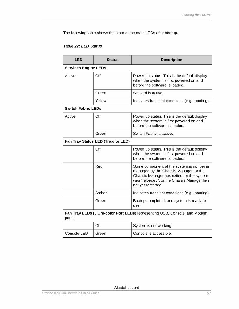
The following table shows the state of the main LEDs after startup.
Table 22: LED Status
LED Status Description
Services Engine LEDs
Active Off Power up status. This is the default display when the system is first powered on and before the software is loaded.
Green SE card is active.
Yellow Indicates transient conditions (e.g., booting).
Switch Fabric LEDs
Active Off Power up status. This is the default display when the system is first powered on and before the software is loaded.
Green Switch Fabric is active.
Fan Tray Status LED (Tricolor LED)
Off Power up status. This is the default display when the system is first powered on and before the software is loaded.
Red Some component of the system is not being managed by the Chassis Manager, or the Chassis Manager has exited, or the system was “reloaded”, or the Chassis Manager has not yet restarted.
Amber Indicates transient conditions (e.g., booting).
Green Bootup completed, and system is ready to use.
Fan Tray LEDs (3 Uni-color Port LEDs) representing USB, Console, and Modem ports
Off System is not working.
Console LED Green Console is accessible.
57Alcatel-Lucent
Beta BetaOmniAccess 780 Hardware User’s Guide

Starting the OmniAccess 780
Left running head: Chapter name (automatic)
Step 3: Configure the system.
Once the system bootup is complete, the system enters the “initial configuration setup” mode, which is an interactive mode for configuring the system. Follow the prompts on the screen to input the required information.
For further customizing and changing the configuration, it would be necessary to use the full-fledged CLI access to the system. To use the CLI and to know more about its usage, refer to the “OmniAccess 700 CLI Configuration Guide”.
Step 4: If all the activities have proceeded normally and if the initial configuration is complete, the OA-780 is installed, and is now ready for deployment in your network.
58
Beta BetaOmniAccess 780 Hardware User’s Guide
Alcatel-Lucent
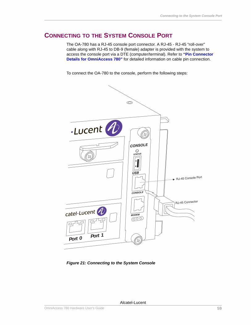
Connecting to the System Console Port
Except on the first page, right running head: Heading1 or Heading1NewPage text (automatic)
CONNECTING TO THE SYSTEM CONSOLE PORTThe OA-780 has a RJ-45 console port connector. A RJ-45 - RJ-45 “roll-over” cable along with RJ-45 to DB-9 (female) adapter is provided with the system to access the console port via a DTE (computer/terminal). Refer to “Pin Connector Details for OmniAccess 780” for detailed information on cable pin connection.
To connect the OA-780 to the console, perform the following steps:
Figure 21: Connecting to the System Console
Port 0 Port 1
59Alcatel-Lucent
Beta BetaOmniAccess 780 Hardware User’s Guide
Starting the OmniAccess 780
Left running head: Chapter name (automatic)
Step 1: Connect the RJ-45 end of the console cable to the front-panel console port on the OA-780 and the DB-9 end to the serial-port (COM) on your computer/terminal.
Step 2: Start your terminal emulation software.
Example: kermit or hyperterm terminal (if you are using Microsoft Windows operating system) or minicom terminal (if you are using Unix/Linux operating system).
Step 3: Set the console session as follows:
Table 23: Console Properties
Step 4: Watch for console message output or press the Enter key to get the device prompt.
Parameter Value
Baud rate 9600
Parity None
Data Bits 8
Stop Bit 1
Flow control None
60
Beta BetaOmniAccess 780 Hardware User’s Guide
Alcatel-Lucent

Performing Basic Configuration Tasks
Except on the first page, right running head: Heading1 or Heading1NewPage text (automatic)
PERFORMING BASIC CONFIGURATION TASKSOnce you boot the OA-780 and connect to the console, you can start configuring your OA-780 either through CLI or Graphical User Interface (GUI).
ACCESSING OA-780 THROUGH CLIThe CLI is the primary interface to access the OA-780 through the console. The CLI allows you to configure, monitor, and troubleshoot the system, and enables network connectivity.
To perform initial configuration of your system, follow the procedure given below:
Step 1: Once the system bootup is complete, you are asked to configure the password for a special user - superadmin. Superadmin is authorized to execute any command. You need to set the superadmin password when the following prompt is displayed:
Enter the new password for superadmin:
Once you enter the password for the superadmin, you will be asked to reconfirm the password, with the following prompt:
Retype the new password:
After confirming the password, you will be asked to login using a username. The below prompt appears.
Username:
Enter the user name as superadmin. Now, you will be prompted for a password.Password:
Enter the newly configured superadmin password.
Note: If you have any pre-existing user account, you can enter at the user name and password prompts, else use the superadmin user account.
Step 2: After entering the correct user name and password, the ALU> prompt is displayed. If the prompt is not seen, press the Enter key a few times.
ALU>
By default, the host name is “ALU”. (To configure a different host name, use the configure “hostname <name>’ command in the Configuration mode.)
Step 3: At the ALU prompt, enter the enable command to enter the Super User Mode (SUM).
Example:ALU> enableALU#
61Alcatel-Lucent
Beta BetaOmniAccess 780 Hardware User’s Guide
Starting the OmniAccess 780
Left running head: Chapter name (automatic)
Step 4: From SUM, you can enter the Configuration Mode (CM). The CM is used to configure the system globally, to enter specific configuration modes, or to configure specific elements, such as interfaces or protocols.
Enter the configure terminal command to enter the Configuration mode.
Example:ALU# configure terminalALU(config)#
The above steps are enough to configure the OA-780 via console.
Step 5: To configure the system remotely (Telnet, SSH, and Modem), you need to configure basic Authentication, Authorization, and Accounting (AAA) configuration. AAA is a system in IP-based networking to control which users have access to the system, what resources users have access to, and to keep track of the activity of users over a network.
To enable the AAA services on your system, enter the aaa services command in Configuration mode.
Example:ALU(config)# aaa services
Step 6: Set the enable password (system password). To set the system password, enter the following command:
enable {secret|password} [5] <password>
Example:ALU(config)# enable secret testSecret for level 15 is set
Note: By default, only the console session is available without the enable password configuration.
62
Beta BetaOmniAccess 780 Hardware User’s Guide
Alcatel-Lucent
Performing Basic Configuration Tasks
Except on the first page, right running head: Heading1 or Heading1NewPage text (automatic)
Step 7: Establish authentication for new users by configuring new user accounts. To configure new user account, use the following command:
username <user-name> {password [5] <password>|nopassword| secret [5] <password>}
Example:ALU(config)# username user1 password pass1
Step 8: Configuring an interface. Enter the following command to enter the Interface Configuration mode:
interface <name> <slot/port>
Example:ALU(config)# interface GigabitEthernet 7/0ALU(config-interfaceGigabitEthernet7/0)#
(For more information on configuring interfaces, refer to the ‘The Command Line Interface’ chapter in the OmniAccess 700 CLI Configuration Guide.)
Step 9: Administratively bring up the interface by using the ‘no shutdown’ command:
Example:ALU(config-if GigabitEthernet7/0)# no shutdown
Step 10: Configure an IP address for the interface by entering the following command. Enter the IP address in the valid IP address format A.B.C.D.
ip address {<ip-address subnet-mask>|<ip-address/prefix-length>}
Example:ALU(config-if GigabitEthernet7/0)# ip address 192.168.1.1/24
Note: In the above example, 192.168.1.1 is assumed to be the GigE 7/0 LAN facing interface and IP address. You can configure the IP address based on your topology.
Step 11: Enable SSH and Telnet for in-band Management. The following command enables SSH/Telnet connection to a remote computer:• Secure Shell (ssh) is a program for logging in to a remote machine that provides
secure communication between two systems.ssh {enable|disable}
Example:ALU(config)# ssh enable
• Telnet is a user command and an underlying TCP/IP protocol for accessing remote computers. Telnet is a program that enables connection to foreign or remote host computers, and provides access to information on them.
telnet {enable|disable}
Example:ALU(config)# telnet enable
63Alcatel-Lucent
Beta BetaOmniAccess 780 Hardware User’s Guide
Starting the OmniAccess 780
Left running head: Chapter name (automatic)
Step 12: Enable HTTP & HTTPS for web-based management.• HTTP is the primary protocol used for the transfer of files over the World Wide
Web. You can access the OA-700 using HTTP through a web browser after being authenticated.
http {enable|disable}
Example:ALU(config)# http enable
• HTTPS, in addition to the normal HTTP uses SSL encryption for secure transmission of files.
Example:ALU(config)# https enable
Step 13: Enable Modem for Out of Band Management.modem {enable|disable}
Example:ALU(config)# modem enable
Step 14: Show Chassis - The ‘show chassis’ command provides a physical inventory of the running chassis components for a specific slot or for the entire system.
Example:ALU> show chassis
Physical inventory at Tue Oct 30 06:33:47 2007System started approximately Tue Oct 30 06:30:26 2007Uptime is 0 days 0 hours 4 minutes 20 seconds
L2 - 8-port copper GigE (active)Slot number: 0Part number: 902603-90Manufacturer: ALUDescription: 8-port copper GigESerial number: DD0512560340Version: 00Revision: 01Deviation: 0000Loader version: 2.27ALU-OS version: 2.2.52MDCSerial number: WL0534000127Deviation: 0001Revision: A1Version: 01
SE - Service engine (active)Slot number: 3Part number: 902601-90Manufacturer: ALUDescription: Service engineSerial number: DD0538002048Version: 01Revision: 04
64
Beta BetaOmniAccess 780 Hardware User’s Guide
Alcatel-Lucent

Performing Basic Configuration Tasks
Except on the first page, right running head: Heading1 or Heading1NewPage text (automatic)
Deviation: 0001CPU Version: 1 (Low Power Opteron)Opteron CPU Version: 1 Opteron CPU Frequency: 2193 MHzLoader version: 2.30ALU-OS version: 2.2.64MDCSerial number: WL0529000008Deviation: 0002Revision: 05Version: 01
PB - Power tray (passive)Slot number: 22Part number: 902612-90Manufacturer: ALUDescription: Power traySerial number: DD0536004050Version: 00Revision: 01Deviation: 0000
SC - Switch card (active)Slot number: 24Part number: 902613-90Manufacturer: ALUDescription: Switch cardSerial number: DD0536054350Version: 00Revision: 54Deviation: aaaaLoL firmware version: 2.2.56Loader version: 2.29ALU-OS version: 2.2.52
FP - Fan tray (passive)Slot number: 26Part number: 902614-90Manufacturer: ALUDescription: Fan traySerial number: DD0545027001Version: 00Revision: 01Deviation: 0000
BP - ALU OA780 chassis (passive)Slot number: 29Part number: 902611-90Manufacturer: ALUDescription: ALU OA780 chassisSerial number: DD0546005005Version: 00Revision: 01Deviation: 0000Base MAC: 00:11:8b:00:72:00
65Alcatel-Lucent
Beta BetaOmniAccess 780 Hardware User’s Guide

Starting the OmniAccess 780
Left running head: Chapter name (automatic)
Step 15: Save the running configuration to the startup configuration.
Example:ALU(config)# write mem
Note: Be sure to save the running configuration. If this is not done, when the system reboots, the configuration is lost.
For further configuration of your OA-780, refer to the OmniAccess 700 CLI Configuration Guide provided in the OA-780 Documentation CD along with your system.
66
Beta BetaOmniAccess 780 Hardware User’s Guide
Alcatel-Lucent
Connecting the System to the Network
Except on the first page, right running head: Heading1 or Heading1NewPage text (automatic)
CONNECTING THE SYSTEM TO THE NETWORKThis section details the procedure to connect to your OA-780 system through the internal network or external network.
CONNECTING THROUGH THE INTERNAL NETWORK
To access the OA-780 through hosts in internal network/LAN, you can use the following:• Accessing OA-780 Through GUI• Connecting Through Telnet• Connecting Through SSH
ACCESSING OA-780 THROUGH GUIFollow the procedure given below to access and configure the OA-780 through a GUI.
Note: To access the OA-780 through the GUI, an IP interface must be configured in your system.
Step 1: Configure IP address of an interface.
To configure an IP address of a given interface, follow the steps detailed in the “Accessing OA-780 Through CLI” section of this document.
Step 2: Open a Web browser from your PC.
Step 3: In the address bar/field, type the IP address of the interface and press the Enter key.
Example:http://<ip address>http://192.168.1.1/24
The login page for the Web GUI is displayed in the browser window.
Step 4: Enter the user name and the password, and press the Enter key. This will launch a web interface to configure your OA-780.
For further configuration of your OA-780, refer to the “OmniAccess 700 Web GUI User Guide” provided in the Documentation CD ROM along with your system.
67Alcatel-Lucent
Beta BetaOmniAccess 780 Hardware User’s Guide
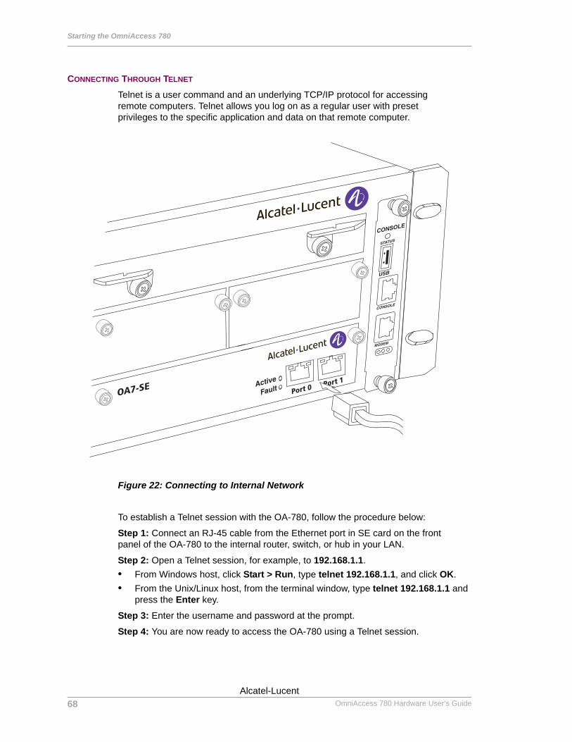
Starting the OmniAccess 780
Left running head: Chapter name (automatic)
CONNECTING THROUGH TELNET
Telnet is a user command and an underlying TCP/IP protocol for accessing remote computers. Telnet allows you log on as a regular user with preset privileges to the specific application and data on that remote computer.
Figure 22: Connecting to Internal Network
To establish a Telnet session with the OA-780, follow the procedure below:
Step 1: Connect an RJ-45 cable from the Ethernet port in SE card on the front panel of the OA-780 to the internal router, switch, or hub in your LAN.
Step 2: Open a Telnet session, for example, to 192.168.1.1.• From Windows host, click Start > Run, type telnet 192.168.1.1, and click OK.• From the Unix/Linux host, from the terminal window, type telnet 192.168.1.1 and
press the Enter key.
Step 3: Enter the username and password at the prompt.
Step 4: You are now ready to access the OA-780 using a Telnet session.
OA7-SE Port 0Port 1
68
Beta BetaOmniAccess 780 Hardware User’s Guide
Alcatel-Lucent
Connecting the System to the Network
Except on the first page, right running head: Heading1 or Heading1NewPage text (automatic)
CONNECTING THROUGH SSHSecure Shell (SSH) is a Unix-based command interface and protocol for securely getting access to a remote computer. SSH uses the RSA public key cryptography for both connection and authentication.
To establish a SSH session with the OA-780, follow the procedure below:
Step 1: Connect an RJ-45 cable from the Ethernet port in the SE card on the front panel of the OA-780 to the router, switch, or hub in your internal network/LAN.
Step 2: Open an SSH session, for example, to 192.168.1.1.
From Unix/Linux host, from the terminal window, type ssh <username>@192.168.1.1 and press the Enter key.
Step 3: Enter the username and password at the prompt. You are now ready to access the OA-780 using a SSH session.
69Alcatel-Lucent
Beta BetaOmniAccess 780 Hardware User’s Guide
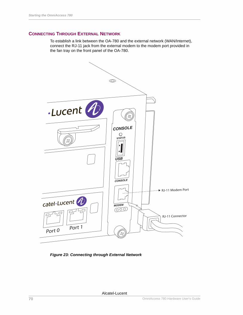
Starting the OmniAccess 780
Left running head: Chapter name (automatic)
CONNECTING THROUGH EXTERNAL NETWORK
To establish a link between the OA-780 and the external network (WAN/Internet), connect the RJ-11 jack from the external modem to the modem port provided in the fan tray on the front panel of the OA-780.
Figure 23: Connecting through External Network
RJ-11 Modem Port
RJ-11 Connector
Port 0 Port 1
70
Beta BetaOmniAccess 780 Hardware User’s Guide
Alcatel-Lucent
Site Log
Except on the first page, right running head: Heading1 or Heading1NewPage text (automatic)
SITE LOGIt is a good practice to maintain a log of the OA-780 to track all activities related to the system. This information also provides valuable history and service record for service personnel. Keep your site log in a common place, near the rack shelf, where anyone who performs tasks has access to it.
Site log entries might include the following:• Installation progress -Make a copy of the System Installation Checklist and insert
it into the site log. Make entries on the Installation Checklist as each procedure is completed.
• Upgrades and removal/replacement procedures - Use the site log as a record of system maintenance and expansion history. Each time a procedure is performed on the system, update the site log to reflect the following:• Any line card removed and replaced• Power supply removals and changes• Configuration changes • Software upgrades• Corrective maintenance procedures performed
• Related comments.
71Alcatel-Lucent
Beta BetaOmniAccess 780 Hardware User’s Guide

Starting the OmniAccess 780
Left running head: Chapter name (automatic)
72
Beta BetaOmniAccess 780 Hardware User’s Guide
Alcatel-Lucent

For final production, import color definitions from\\daldoc01\docteam\templates\framemaker\book-template\color-defs\ production-colors.fm. Do not import other template elements such as page layout.
To return to the draft version, import color def’ns from draft-colors.fm.To switch to the beta version, import color def’ns from beta-colors.fm
Optional footer: Manual title (to set, redefine ManualTitlevariable)
Appendix A
agination: umeric & ntinuous
PNco
Regulatory Compliance and Safety Information
This appendix provides information on regulatory agency compliance and safety for the OmniAccess 780 (OA-780).
DECLARATION OF CONFORMITY: CE MARKThis equipment is in compliance with the essential requirements and other provisions of Directive 73/23/EEC and 89/336/EEC as amended by Directive 93/68/EEC.
Français: Ce matériel est conformément aux conditions essentielles et à d'autres dispositions de 73/23/EEC et de 89/336/EEC directifs comme modifié par Directive 93/68/EEC.
Deutsch: Konformitätserklärung: CE Kennzeichnung Diese Anlage ist gemäß den wesentlichen Anforderungen und anderen Bestimmungen richtungweisenden 73/23/EEC und des 89/336/EEC, wie von Directive 93/68/EEC geändert.
Español: Este directivo equipo está en conformidad con los requisitos esenciales y otras provisiones 73/23/EEC y 89/336/EEC según la enmienda prevista por Directive 93/68/EEC.
Beta BetaAlcatel-Lucent
1
Beta Betawith preceding section of book
OmniAccess 780 Hardware User’s Guide
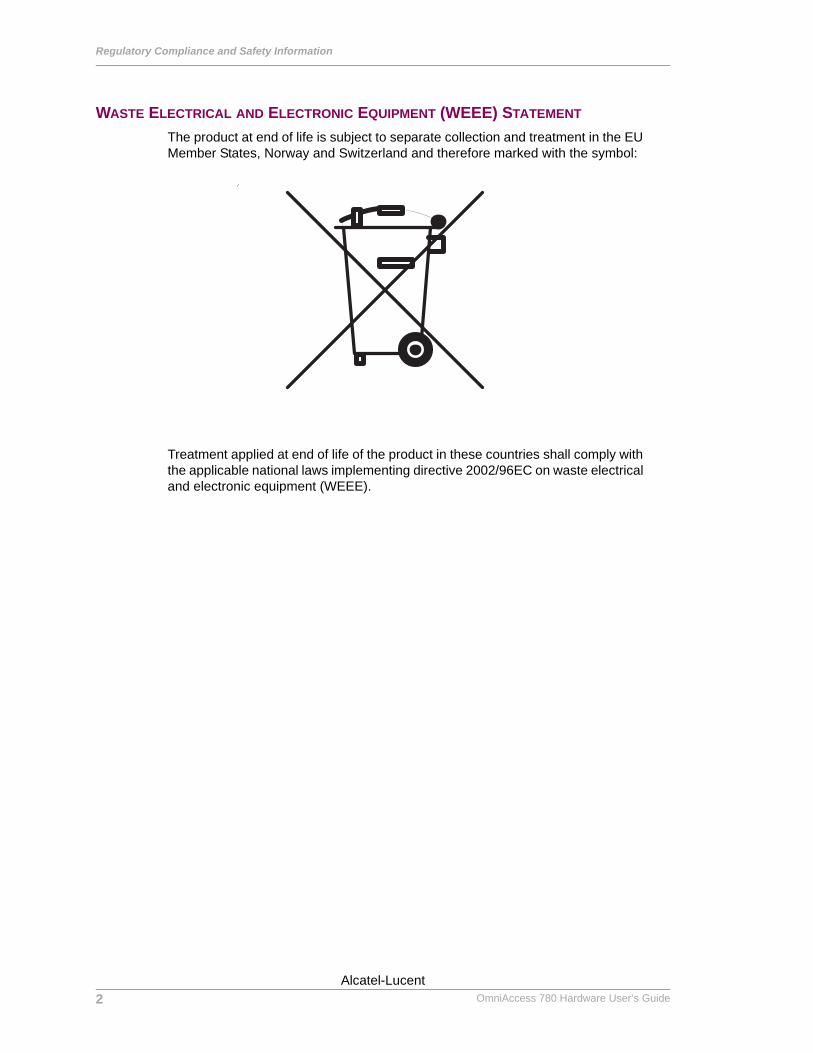
Regulatory Compliance and Safety Information
Left running head: Chapter name (automatic)
WASTE ELECTRICAL AND ELECTRONIC EQUIPMENT (WEEE) STATEMENT
The product at end of life is subject to separate collection and treatment in the EU Member States, Norway and Switzerland and therefore marked with the symbol:
Treatment applied at end of life of the product in these countries shall comply with the applicable national laws implementing directive 2002/96EC on waste electrical and electronic equipment (WEEE).
2
Beta BetaOmniAccess 780 Hardware User’s Guide
Alcatel-Lucent
China RoHS: Hazardous Substance Table
Except on the first page, right running head: Heading1 or Heading1NewPage text (automatic)
CHINA ROHS: HAZARDOUS SUBSTANCE TABLE
产品说明书附件 SUPPLEMENT TO PRODUCT INSTRUCTIONS
有毒有害物质或元素 (Hazardous Substance) 部件名称
(Parts) 铅
(Pb) 汞
(Hg) 镉
(Cd) 六价铬
(Cr6+)
多溴联苯
(PBB) 多溴二苯醚
(PBDE) 电路模块
(Circuit Modules) × ○ ○ ○ ○ ○
电缆及电缆组件
(Cables & Cable Assemblies) × ○ ○ ○ ○ ○
金属部件
(Metal Parts) × ○ ○ ○ ○ ○
塑料和聚合物部件
(Plastic and Polymeric parts) ○ ○ ○ ○ ○ ○
对于交付时集成了电池的电子信息产品 For electronic information products delivered with integrated functional batteries:
电池
(Batteries) ○ ○ ○ ○ ○ ○
○: 表示该有毒有害物质在该部件所有均质材料中的含量均在 SJ/T11363-2006 标准规定的限量要求以下。
Indicates that the concentration of the hazardous substance in all homogeneous materials in the parts is below the relevant threshold of the SJ/T11363-2006 standard.
×: 表示该有毒有害物质至少在该部件的某一均质材料中的含量超出SJ/T11363-2006标准规定的限量要求。
Indicates that the concentration of the hazardous substance of at least one of all homogeneous materials in the parts is above the relevant threshold of the SJ/T11363-2006 standard.
对销售之日的所售产品,本表显示, 阿尔卡特朗讯公司供应链的电子信息产品可能包含这些物质。注意:在所售产
品中可能会也可能不会含有所有所列的部件。
This table shows where these substances may be found in the supply chain of Alcatel-Lucent electronic information products, as of the date of sale of the enclosed product. Note that some of the component
types listed above may or may not be a part of the enclosed product.
这个文件涉及的是在中华人民共和国境内进口或销售的电子信息产品 Include this document with all Electronic Information Products imported
or sold in the People’s Republic of China
除非另外特别的标注,此标志为针对所涉及产品的环保使用期标志. 某些零部件会有
一个不同的环保使用期(例如,电池单元模块)贴在其产品上.
此环保使用期限只适用于产品是在产品手册中所规定的条件下工作. The Environment- Friendly Use Period (EFUP) for all enclosed products and their parts are per the symbol shown here, unless otherwise marked. Certain parts may have a different EFUP (for example, battery modules) and so are marked to reflect such. The Environment- Friendly Use Period is valid only when the product is operated under the conditions defined in the product manual.
3Alcatel-Lucent
Beta BetaOmniAccess 780 Hardware User’s Guide
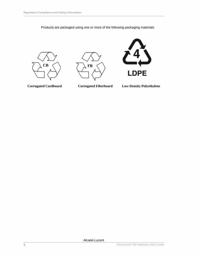
Regulatory Compliance and Safety Information
Left running head: Chapter name (automatic)
Products are packaged using one or more of the following packaging materials:
Corrugated Cardboard Corrugated Fiberboard Low-Density Polyethylene
CB FB
4
Beta BetaOmniAccess 780 Hardware User’s Guide
Alcatel-Lucent
Standards Compliance
Except on the first page, right running head: Heading1 or Heading1NewPage text (automatic)
STANDARDS COMPLIANCEThe product bears the CE mark. In addition it is in compliance with the following other safety and EMC standards:
All hardware switching modules used in an OA-780 comply with Class A standards. Modules with copper connectors meet Class A requirements using unshielded (UTP) cables.
SAFETY• UL60950-1:2003• CSA 22.2 No. 60950-1:2003• EN 60950• IEC 60950-1:2001
EMC• FCC Part 15, Subpart B• ICES 003• EN 55022:1998/A1:2000• EN 55024• AS/NZS 3548:1995+A1:1997+A2:1997• VCCI V-3/2000.04
TELECOM• 47, CFR Part 68 AND ACTA, Adopted Technical Criteria• CS 03 Issue 8, Part II• TBR 12 AND TBR 13• AS/ACTF S016: 2001• T1(DS1) JATE - 1.544 Mbit/sec Digital Interface• E1 JATE - 2.048 Mbit/sec Digital Interface
5Alcatel-Lucent
Beta BetaOmniAccess 780 Hardware User’s Guide
Regulatory Compliance and Safety Information
Left running head: Chapter name (automatic)
DECLARATION OF CONFORMITY ADDENDUM
Application of Council Directive(s) 89/336/EEC73/23/EEC1999/5/EEC
Manufacturer’s Name Alcatel-Lucent
Manufacturer’s Address 26801 West Agoura RoadCalabasas, CA 91301Tel: 818-880-3500Fax: 818-880-3505Website: www.alcatel-lucent.com
Conformance to Directive(s)/Product Standards
EC Directive 89/336/EECEC Directive 73/23/EECEC Directive 1999/5/EECEN 55022:1998+A1:2000+A2:2003EN 61000-3-2:2000EN 61000-3-3:1995+A1:2001EN 55024:1998+A1:2001EN 61000-4-2:2001EN 61000-4-3:2002EN 61000-4-4:1995+A1:2000+A2:2001EN 61000-4-5:2001EN 61000-4-6:2001EN 61000-4-8:2001EN 61000-4-11:2001EN 55024:1998+A1:2001EN60555-2: 1995EN 60950-1:2001+A11CB SchemeETSI EN 300 386 v1.4.1(2000-2003)ETSI TBR 012ETSI TBR 013
6
Beta BetaOmniAccess 780 Hardware User’s Guide
Alcatel-Lucent

Standards Compliance
Except on the first page, right running head: Heading1 or Heading1NewPage text (automatic)
FCC CLASS A, PART 15This equipment has been tested and found to comply with the limits for Class A digital device pursuant to Part 15 of the FCC Rules.These limits are designed to provide reasonable protection against harmful interference when the equipment is operated in a commercial environment.This equipment generates, uses, and can radiate radio frequency energy and, if not installed and used in accordance with the instructions in this guide, may cause interference to radio communications. Operation of this equipment in a residential area is likely to cause interference, in which case the user will be required to correct the interference at his own expense.
The user is cautioned that changes and modifications made to the equipment without approval of the manufacturer could void the user’s authority to operate this equipment.It is suggested that the user use only shielded and grounded cables to ensure compliance with FCC Rules.
If this equipment does cause interference to radio or television reception, the user is encouraged to try to correct the interference by one or more of the following measures:• Reorient the receiving antenna.• Relocate the equipment with respect to the receiver.• Move the equipment away from the receiver.• Plug the equipment into a different outlet so that equipment and receiver are on
different branch circuits.
If necessary, the user should consult the dealer or an experienced radio/television technician for additional suggestions.
7Alcatel-Lucent
Beta BetaOmniAccess 780 Hardware User’s Guide

Regulatory Compliance and Safety Information
Left running head: Chapter name (automatic)
CANADA CLASS A STATEMENT
This equipment does not exceed Class A limits per radio noise emissions for digital apparatus, set out in the Radio Interference Regulation of the Canadian Department of Communications.
AVIS DE CONFORMITÈ AUX NORMES DU MINISTÈRE DES COMMUNICATIONS DU CANADA Cet èquipement ne dèpasse pas les limites de Classe A d íèmission de bruits radioèlectriques pour les appareils numèriques,telles que prescrites par le RÈglement sur le brouillage radioèlectrique ètabli par le ministère des Communications du Canada.
JATEThis equipment meets the requirements of the Japan Approvals Institute of Telecommunications Equipment (JATE).
CISPR22 CLASS A WARNING
This is a Class A product. In a domestic environment, this product may cause radio interference. Under such circumstances, the user may be requested to take appropriate countermeasures.
VCCIThis is a Class A product based on the standard of the Voluntary Control Council for Interference by Information Technology Equipment (VCCI). If this equipment is used in a domestic environment, radio disturbance may arise. When such trouble occurs, the user may be required to take corrective actions.
8
Beta BetaOmniAccess 780 Hardware User’s Guide
Alcatel-Lucent
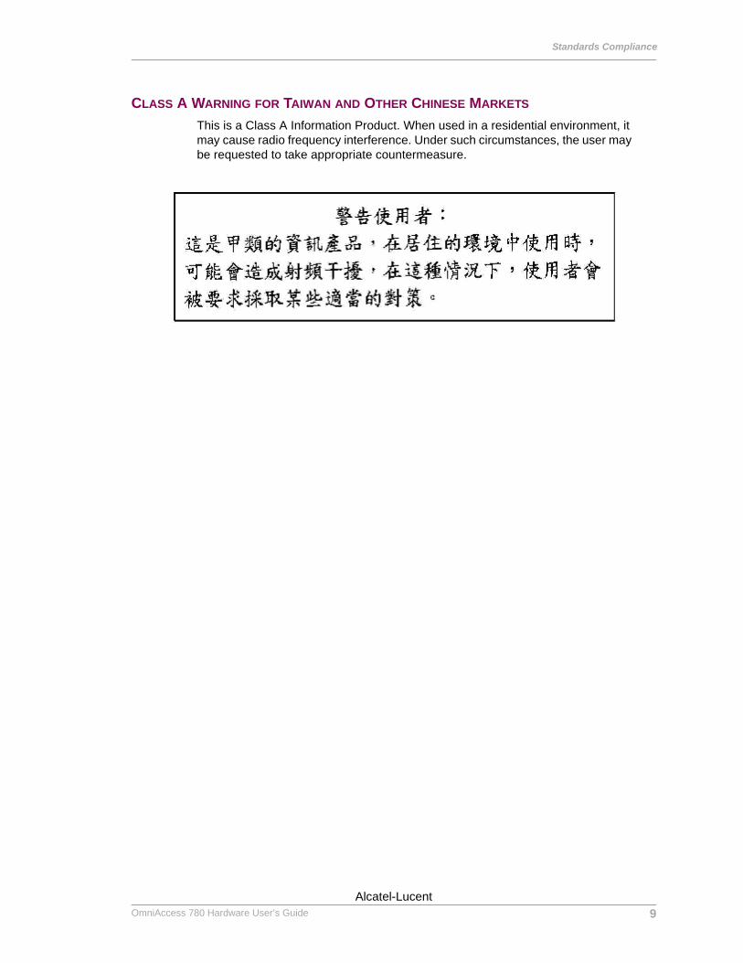
Standards Compliance
Except on the first page, right running head: Heading1 or Heading1NewPage text (automatic)
CLASS A WARNING FOR TAIWAN AND OTHER CHINESE MARKETS
This is a Class A Information Product. When used in a residential environment, it may cause radio frequency interference. Under such circumstances, the user may be requested to take appropriate countermeasure.
9Alcatel-Lucent
Beta BetaOmniAccess 780 Hardware User’s Guide

Regulatory Compliance and Safety Information
Left running head: Chapter name (automatic)
TRANSLATED SAFETY WARNINGS
CHASSIS LIFTING WARNING
Two people are required when lifting the chassis. Due to its weight, lifting the chassis unassisted can cause personal injury. Also be sure to bend your knees and keep your back straight when assisting with the lifting of the chassis.
Français: Le châssis doit être soulevé par deux personnes au minimum. Pour éviter tout risque d'accident, maintenez le dos droit et poussez sur vos jambes. Ne soulevez pas l'unité avec votre dos.
Deutsch: Sicherheitshinweise Hinweise zur Anhebung des Chassis
Zum Anheben des Chassis werden zwei Personen benötigt. Aufgrund des Gewichts kann das Anheben ohne Unterstützung zu Personenschäden führen. Heben Sie das Chassis aus den Knien und halten Sie den Rücken gerade wenn Sie beim Anheben des Chassis assistieren.
Español: Se requieren dos personas para elevar el chasis. Para evitar lesiones, mantenga su espalda en posición recta y levante con sus piernas, no con su espalda.
BLANK PANELS WARNING
Because they regulate airflow and help protect internal chassis components, blank cover plates should remain installed at empty module slots and power supply bays at all times.
Français: Les caches blancs remplissent trois fonctions importantes : ils évitent tout risque de choc électrique à l'intérieur du châssis, ils font barrage aux interférences électromagnétiques susceptibles d'altérer le fonctionnement des autres équipements et ils dirigent le flux d'air de refroidissement dans le châssis. Il est vivement recommandé de vérifier que tous les caches, modules d'alimentation et plaques de protection sont en place avant d'utiliser le système.
Deutsch: Hinweise zu AbdeckungenDie leeren Modulblenden schützen interne Komponenten und leiten den Luftstrom. Deshalb müssen in allen unbelegten Slots die Modulblenden immer installiert bleiben.
Español: Las tapaderas blancas regulan la circulación de aire y ayudan a proteger componentes internos del chasis y siempre deben estar instaladas en las ranuras vacías del chasis y fuentes de alimentación.
10
Beta BetaOmniAccess 780 Hardware User’s Guide
Alcatel-Lucent
Translated Safety Warnings
Except on the first page, right running head: Heading1 or Heading1NewPage text (automatic)
ELECTRICAL STORM WARNING
To avoid a shock hazard, do not connect or disconnect any cables or perform installation, maintenance, or reconfiguration of this product during an electrical storm.
Français: Ne pas travailler sur le système ni brancher ou débrancher les câbles pendant un orage.
Deutsch: Hinweise bei UnwetterUm elektrische Schläge zu vermeiden dürfen während eines Gewitters and diesem Gerät keine Kabel angeschlossen oder gelöst werden, sowie keinerlei Installationen, Wartungen oder Konfigurationen vorgenommen werden.
Español: Para evitar peligro de descargas, no conecte o desconecte ningun cable, ni realice ninguna instalación, maintenimiento o reconfiguración de este producto durante una tormenta eléctrica.
INSTALLATION WARNING
Only personnel knowledgeable in basic electrical and mechanical procedures should install or maintain this equipment.
Français: Toute installation ou remplacement de l'appareil doit être réalisée par du personnel qualifié et compétent.
Deutsch: InstallationshinweiseDieses Gerät soll nur von Personal installiert oder gewartet werden, welches in elektrischen und mechanischen Grundlagen ausgebildet ist.
Español: Estos equipos deben ser instalados y atendidos exclusivamente por personal adecuadamente formado y capacitado en técnicas eléctricas y mecánicas.
INVISIBLE LASER RADIATION WARNING
Lasers emit invisible radiation from the aperture opening when no fiber-optic cable is connected. When removing cables do not stare into the open apertures. In addition, install protective aperture covers to fiber ports with no cable connected.
Français: Des radiations invisibles à l'œil nu pouvant traverser l'ouverture du port lorsque aucun câble en fibre optique n'y est connecté, il est recommandé de ne pas regarder fixement l'intérieur de ces ouvertures. Installez les caches connecteurs prévus à cet effet.
Deutsch: Hinweise zur unsichtbaren LaserstrahlungDie Laser strahlen an der Blendenöffnung unsichtbares Licht ab, wenn keine Glasfaserkabel angeschlossen sind. Blicken Sie nicht in die Öffnungen und installieren Sie unverzüglich die Abdeckungen über den Glasfaseranschlüssen.
Español: Debido a que la apertura del puerto puede emitir radiación invisible cuando no hay un cable de fibra conectado, procurar no mirar directamente a las aperturas para no exponerse a la radiación.
11Alcatel-Lucent
Beta BetaOmniAccess 780 Hardware User’s Guide
Regulatory Compliance and Safety Information
Left running head: Chapter name (automatic)
BATTERY WARNING
There is a danger of explosion if the battery in your chassis is incorrectly replaced. Replace the battery only with the same or equivalent type of battery recommended by the manufacturer. Dispose of used batteries according to the manufacturer’s instructions. The manufacturer’s instructions are as follows: Return the module with the battery to Alcatel-Lucent. The battery will be replaced at Alcatel-Lucent’s factory.
Français: Il y a un danger d'explosion si la batterie dans votre châssis est remplacée avec une autre ne correspondant pas aux préconisations constructeur. Il faut donc renvoyer le module en réparation chez Alcatel-Lucent qui se chargera de remplacer la batterie.
Deutsch: Hinweise BatterieBei falschem Einsetzen der batterie in das Gerät besteht die Gefahr der Explosion. Bitte ersetzen Sie die Batterie nur durch den gleichen bzw. gleichwertigen Typ, empfohlen durch den Hersteller. Benutzte Batterien entsorgen sie bitte wie folgt: Bitte senden Sie das Modul zurück zu Alcatel-Lucent. Dort wird die gebrauchte Batterie ersetzt.
Español: Si substituye las pilas de litio en su chasis, siempre utilice el mismo modelo o el tipo equivalente de pila recomendada por el fabricante. Deshágase de las pilas usadas según las instrucciones del fabricante. Devuelva el módulo con la pila de litio a Alcatel-Lucent. La pila de litio será substituida en la fábrica de Alcatel-Lucent.
Dansk: ADVARSEL! batteri--Eksplosionsfare ved fejlagtig handtering. Udskiftning ma kun ske batteri af samme fabrikat og type. Lever det brugte batteri tilbage tilleverandoren.
OPERATING VOLTAGE WARNING
To reduce the risk of electrical shock, keep your hands and fingers out of power supply bays and do not touch the backplane while the switch is operating.
Français: Pour réduire tout risque électrique, gardez vos mains et doigts hors des alimentations et ne touchez pas au fond de panier pendant que le commutateur fonctionne.
Deutsch: Hinweise gegen elektrischen SchlagUm die Gefahr des elektrischen Schlages zu verringern, greifen sie bitte nicht in die Spannungsversorgung und berühren sie nicht die Rückwandplatine während das Gerät arbeitet.
Español: Para reducir el riesgo de descargas eléctricas, no meta sus manos y dedos dentro del chasis de la fuente de alimentación y no toque componentes internos mientras que el interruptor está conectado.
12
Beta BetaOmniAccess 780 Hardware User’s Guide
Alcatel-Lucent
Translated Safety Warnings
Except on the first page, right running head: Heading1 or Heading1NewPage text (automatic)
POWER DISCONNECTION WARNING
Your switch is equipped with multiple power supplies. To reduce the risk of electrical shock, be sure to disconnect all power connections before servicing or moving the unit.
Français: Il se peut que cette unité soit équipée de plusieurs raccordements d'alimentation. Pour supprimer tout courant électrique de l'unité, tous les cordons d'alimentation doivent être débranchés.
Deutsch: Hinweise zur SpannungsfreischaltungIhr Gerät ist mit mehreren Netzteilen ausgerüstet. Um die Gefahr des elektrischen Schlages zu verringern, stellen sie sicher, daß alle Netzverbindungen getrennt sind bevor das Gerät gewartet oder bewegt wird.
Español: Antes de empezar a trabajar con un sistema, asegurese que el interruptor está cerrado y el cable eléctrico desconectado.
PROPER EARTHING REQUIREMENT WARNING
To avoid shock hazard:• The power cord must be connected to a properly wired and earth receptacle.• Any equipment to which this product will attached must also be connected to
properly wired receptacles.
Français:Pour éviter tout risque de choc électrique:• Ne jamais rendre inopérant le conducteur de masse ni utiliser l'équipement sans
un conducteur de masse adéquatement installé.• En cas de doute sur la mise à la masse appropriée disponible, s'adresser à
l'organisme responsable de la sécurité électrique ou à un électricien.
Deutsch: Hinweise zur geforderten Erdung des Gerätes
Aus Sicherheitsgründen:• darf das Netzkabel nur an eine Schutzkontaktsteckdose angeschloossen werden.• dürfen für den Anschluß anderer Geräte, welche mit diesem Gerät verbunden
sind, auch nur Schutzkontaktsteckdosen verwendet werden.
Español: Para evitar peligro de descargas:• Para evitar peligro de descargas asegurese de que el cable de alimentación está
conectado a una toma de alimentación adecuadamente cableada y con toma de tierra.
• Cualquier otro equipo a cual se conecte este producto también debe estar conectado a tomas de alimentación adecuadamente cableadas.
13Alcatel-Lucent
Beta BetaOmniAccess 780 Hardware User’s Guide
Regulatory Compliance and Safety Information
Left running head: Chapter name (automatic)
READ IMPORTANT SAFETY INFORMATION WARNING
The Getting Started Guide that accompanied this equipment contains important safety information about which you should be aware when working with hardware components in this system. You should read this guide before installing, using, or servicing this equipment.
Français: Avant de brancher le système sur la source d'alimentation, consultez les directives d'installation disponibles dans le “Getting Started Guide”.
Deutsch: Bitte lesen - SicherheitshinweiseDer Getting Started Guide, welcher diese Anlage beiliegt, enthält wichtige Sicherheitsinformationen, über die sie sich beim Arbeiten mit den Hardwareeinheiten bewußt sein sollten. Sie sollten diese Hinweise lesen, bevor sie installieren, reparieren oder die Anlage verwenden.
Español: La 'Getting Started Guide' que acompañó este equipo contiene información importante de seguridad sobre la cual usted debe estar enterado al trabajar con los componentes de dotación física en este sistema. Usted debe leer esta guía antes de instalar, usar o mantener este equipo.
RESTRICTED ACCESS LOCATION WARNING
This equipment should be installed in a location that restricts access. A restricted access location is one where access is secure and limited to service personnel who have a special key, or other means of security.
Français: Le matériel doit être installé dans un local avec accès limité ou seules les personnes habilitées peuvent entrer.
Deutsch: Hinweis zu Umgebungen mit beschränktem ZutrittDie Anlage sollte an einem Standort mit beschränktem Zutritt installiert sein. Ein Standort mit beschränktem Zutritt stellt sicher, daß dort nur Servicepersonal mit Hilfe eines Schlüssels oder eines anderen Sicherheitssystems Zugang hat.
Español: Este equipo se debe instalar en un sitio con acceso restrinjido. Un sitio con el acceso restrinjido es uno seguro y con acceso limitado al personal de servicio que tiene una clave especial u otros medios de seguridad.
14
Beta BetaOmniAccess 780 Hardware User’s Guide
Alcatel-Lucent

Translated Safety Warnings
Except on the first page, right running head: Heading1 or Heading1NewPage text (automatic)
WRIST STRAP WARNING
Because electrostatic discharge (ESD) can damage switch components, you must ground yourself properly before continuing with the hardware installation. For this purpose, Alcatel-Lucent provides a grounding wrist strap and a grounding lug located near the top-right of the chassis. For the grounding wrist strap to be effective in eliminating ESD, the power supplies must be installed in the chassis and plugged into grounded AC outlets.
Français: L'électricité statique (ESD) peut endommager les composants du commutateur. Pour cette raison Alcatel-Lucent joint à l'envoi du châssis un bracelet antistatique à brancher sur la prise mise à la terre située en bas à droite du commutateur. Vous devrez mettre ce bracelet avant toute intervention hardware.
Deutsch: Hinweise zur ESD (Elektrostatischen Aufladung)Weil elektrostatische Aufladung (ESD) Teile der Anlage beschädigen könnten, müssen sie sich selbst erden, bevor sie mit der Hardware Installation beginnen. Zu diesem Zweck stellt Alcatel-Lucent ein Erdungsarmband und eine Erdungsöse an der oberen rechten Seite des Chassis zur Verfügung. Um eine sichere Erdungsfunktion des Erdungsarmbandes sicherzustellen, müssen die Netzteile installiert und mit dem Schutzleiter des Versorgungsstromkreises verbunden sein.
Español: La descarga electrostática (ESD) puede dañar componentes eletrónicos. Usted debe asegurarse que está en contacto con tierra antes de hacer la instalación del equipo. Con este fin, Alcatel-Lucent proporciona una pulsera de muñeca para conectar al chasis en la toma de tierra situada en la parte superior derecha del chasis. Para que la correa de muñeca sea eficaz en la eliminación de ESD, las fuentes de alimentación deben estar instaladas en el chasis y conectadas a enchufes CA con tierra adecuada.
15Alcatel-Lucent
Beta BetaOmniAccess 780 Hardware User’s Guide
Regulatory Compliance and Safety Information
Left running head: Chapter name (automatic)
INSTRUCCIONES DE SEGURIDAD EN ESPAÑOL
ADVERTENCIA SOBRE EL LEVANTAMIENTO DEL CHASIS
Se requieren dos personas para levantar el chasis. Debido a su peso, la elevación del chasis sin ayuda puede causar daños corporales. También es seguro doblar sus rodillas y guardar su espalda derecho al ayudar a levantar el chasis.
ADVERTENCIA DE LAS TAPADERAS EN BLANCO
Porque regulan la circulación de aire y ayudan a proteger componentes internos del chasis, las tapaderas en blanco deben seguir instaladas en las ranuras vacías del módulo y la fuente de alimentación siempre.
ADVERTENCIA EN CASO DE TORMENTA ELÉCTRICA
Para evitar peligro de descargas, no conecte o desconecte ningun cable, ni realice ninguna instalación, maintenimiento o reconfiguratión de este producto durante una tormenta eléctrica.
ADVERTENCIA DE INSTALACIÓN
Solamente el personal bien informado en procedimientos eléctricos y mecánicos básicos debe instalar o mantener este equipo.
ADVERTENCIA DE RADIACIÓN LÁSER INVISIBLE
Los lasers emiten radiación invisible de la apertura abierta cuando no se conecta ningún cable de fibra óptica. Al quitar los cables no mire fijamente en las aberturas abiertas. Además, instale las cubiertas protectoras de la abertura a las salidas de la fibra sin el cable conectado.
ADVERTENCIA DE LA BATERÍA DE LITIO
Hay un peligro de la explosión si la batería del litio en su chasis se substituye incorrectamente. Substituya la batería solamente por el mismo o el equivalente de tipo de batería recomendado por el fabricante. Deseche las baterías usadas según las instrucciones del fabricante. Las instrucciones del fabricante son como sigue: Devuelva el módulo con la batería del litio a Alcatel-Lucent. La batería del litio será substituida en la fábrica de Alcatel-Lucent.
ADVERTENCIA SOBRE LA TENSIÓN DE OPERACIÓN
Para reducir el riesgo del choque eléctrico, matenga sus manos y dedos fuera de la fuente de alimentación y no toque la placa madre mientras que el interruptor está funcionando.
ADVERTENCIA SOBRE LA DESCONEXIÓN DE LA FUENTE
Su interruptor esta equipado por fuentes de alimentación múltiples. Para reducir el riesgo de choque eléctrico, asegúrese desconectar todas las conexiones de alimentación antes de mantener o de mover la unidad.
16
Beta BetaOmniAccess 780 Hardware User’s Guide
Alcatel-Lucent
Instrucciones de seguridad en español
Except on the first page, right running head: Heading1 or Heading1NewPage text (automatic)
ADVERTENCIA SOBRE UNA APROPIADA CONEXIÓN A TIERRA
Para evitar peligro de descargas:• El cable de alimentación debe estar conectado a una toma de alimentación
adecuadamente cableada y con toma de tierra.
Cualquier equipo al cual se conecte este producto debe estar también conectado a tomas de alimentación adecuadamente cableadas.
LEER “INFORMACIÓN IMPORTANTE DE SEGURIDAD”La Guía de “Comenzando a Usar” que acompaña este equipo contiene información importante de seguridad sobre la cual usted debe saber al trabajar con los componentes de dotación física en este sistema. Usted debe leer esta guía antes de instalar, de usar, o de mantener este equipo.
ADVERTENCIA DE ACCESO RESTRINGIDO
Este equipo se debe instalar en una ubicación que restrinja el acceso. Una ubicación con acceso restringido es una donde está seguro y limitado el acceso al personal de servicio que tiene un clave especial, u otros medios de la seguridad.
ADVERTENCIA DE PULSERA ANTIESTÁTICA
Debido a que la descarga electrostática (ESD) puede dañar componentes del interruptor, usted debe conectarse a tierra correctamente antes de continuar con la instalación del equipo. Para este propósito, Alcatel-Lucent proporciona una pulsera antiestática y un terminal que pone a tierra situados cerca de la parte superior derecha del chasis. Para que la pulsera antiestática sea eficaz en la eliminación de ESD, las fuentes de alimentación se deben instalar en el chasis y enchufar en las salidas de CA con descarga a tierra.
CLASE DE SEGURIDAD
Cumple con 21CFR 1040.10 y 1040.11 ó sus equivalentes.
ADVERTENCIA DE FUENTES DE PODER
Las unidades OmniAccess 780 pueden estar equipadas con tres cordones para fuente de poder. Para reducir el riesgo de un choque electrico, desconecte todos los cordones de fuente de poder antes de dar servicio a la unidad.
17Alcatel-Lucent
Beta BetaOmniAccess 780 Hardware User’s Guide

Regulatory Compliance and Safety Information
Left running head: Chapter name (automatic)
18
Beta BetaOmniAccess 780 Hardware User’s Guide
Alcatel-Lucent

For final production, import color definitions from\\daldoc01\docteam\templates\framemaker\book-template\color-defs\ production-colors.fm. Do not import other template elements such as page layout.
To return to the draft version, import color def’ns from draft-colors.fm.To switch to the beta version, import color def’ns from beta-colors.fm
Optional footer: Manual title (to set, redefine ManualTitlevariable)
Appendix B
agination: umeric & ntinuous
PNco
AC Power Specifications
The OA-780 requires AC-input power supply in the range between 100 and 240V. The AC-input power supply uses a power factor correction that complies to EN61000-3-2.
Table 1 lists the AC-input power supply specifications.
Table 1: AC Power Supply Specifications
Description Specification
Input
Input voltage 100 to 240 VAC
Input frequency 47 to 63 Hz
Output
Power output 350 W
Efficiency 65% at minimum measured at nominal AC main voltage and frequency with maximum load on all output
Environmental Characteristics
Power Supply Dimensions (H x W x D)
3.9 x 1.6 x 8.7 inches (10 x 4.05 x 22 centimeters)
Temperature, operating 0 to 40°C
Temperature, non- operating (storage and shipping)
-25 to 70°C
Humidity 10 - 90% (non-condensing)
Beta BetaAlcatel-Lucent
19
Beta Betawith preceding section of book
OmniAccess 780 Hardware User’s Guide

AC Power Specifications
Left running head: Chapter name (automatic)
Regulatory compliance
Agency approvals UL 1950, CSA C22.2 Level 3, TUV EN60950 or VDE EN60950, NEMKO EN60950 (CB Report), CEComplies with FCC part 15 subpart J Class B and CISPR 22 Class B
Description Specification
20
Beta BetaOmniAccess 780 Hardware User’s Guide
Alcatel-Lucent

For final production, import color definitions from\\daldoc01\docteam\templates\framemaker\book-template\color-defs\ production-colors.fm. Do not import other template elements such as page layout.
To return to the draft version, import color def’ns from draft-colors.fm.To switch to the beta version, import color def’ns from beta-colors.fm
Optional footer: Manual title (to set, redefine ManualTitlevariable)
Appendix C
agination: umeric & ntinuous
PNco
Pin Connector Details for OmniAccess 780
This section describes pin connection details for the OmniAccess 780 (OA-780).
RJ-11 MODEM CONNECTOR PIN ASSIGNMENTS
This section details modem connector pin (RJ-11) details for the OA-780.
Figure 1: RJ-11 Connector
Table 1: Pin Connector Details for RJ-11 Connector
RJ-11 Connector Pin Number Signal Name
1 NC
2 Tip or Ring
3 Ring or Tip
4 NC
4 3 2 1
Beta BetaAlcatel-Lucent
21
Beta Betawith preceding section of book
OmniAccess 780 Hardware User’s Guide
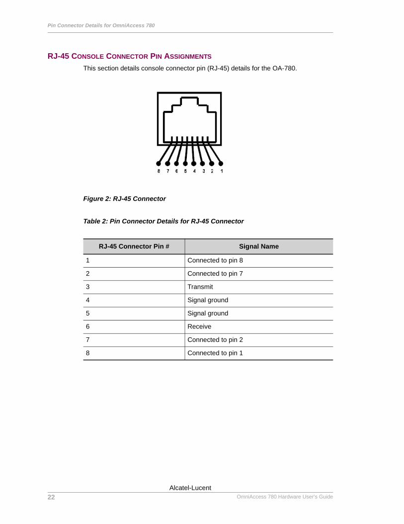
Pin Connector Details for OmniAccess 780
Left running head: Chapter name (automatic)
RJ-45 CONSOLE CONNECTOR PIN ASSIGNMENTS
This section details console connector pin (RJ-45) details for the OA-780.
Figure 2: RJ-45 Connector
Table 2: Pin Connector Details for RJ-45 Connector
RJ-45 Connector Pin # Signal Name
1 Connected to pin 8
2 Connected to pin 7
3 Transmit
4 Signal ground
5 Signal ground
6 Receive
7 Connected to pin 2
8 Connected to pin 1
22
Beta BetaOmniAccess 780 Hardware User’s Guide
Alcatel-Lucent
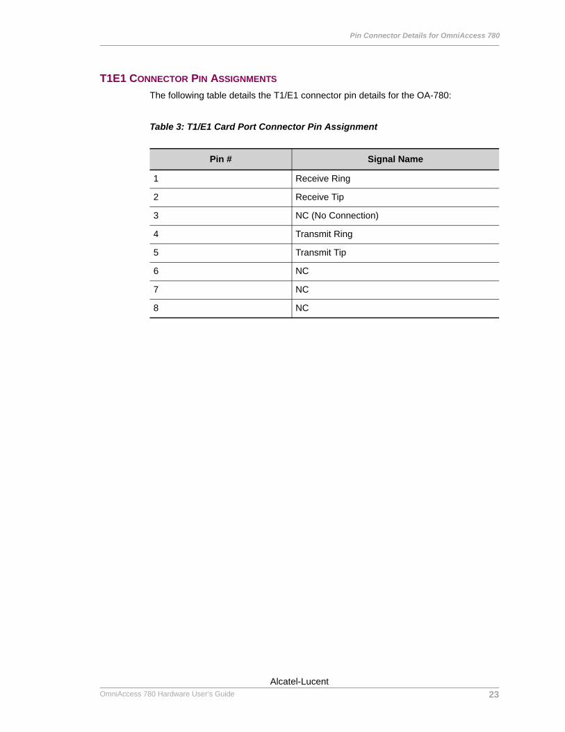
Pin Connector Details for OmniAccess 780
Except on the first page, right running head: Heading1 or Heading1NewPage text (automatic)
T1E1 CONNECTOR PIN ASSIGNMENTS
The following table details the T1/E1 connector pin details for the OA-780:
Table 3: T1/E1 Card Port Connector Pin Assignment
Pin # Signal Name
1 Receive Ring
2 Receive Tip
3 NC (No Connection)
4 Transmit Ring
5 Transmit Tip
6 NC
7 NC
8 NC
23Alcatel-Lucent
Beta BetaOmniAccess 780 Hardware User’s Guide
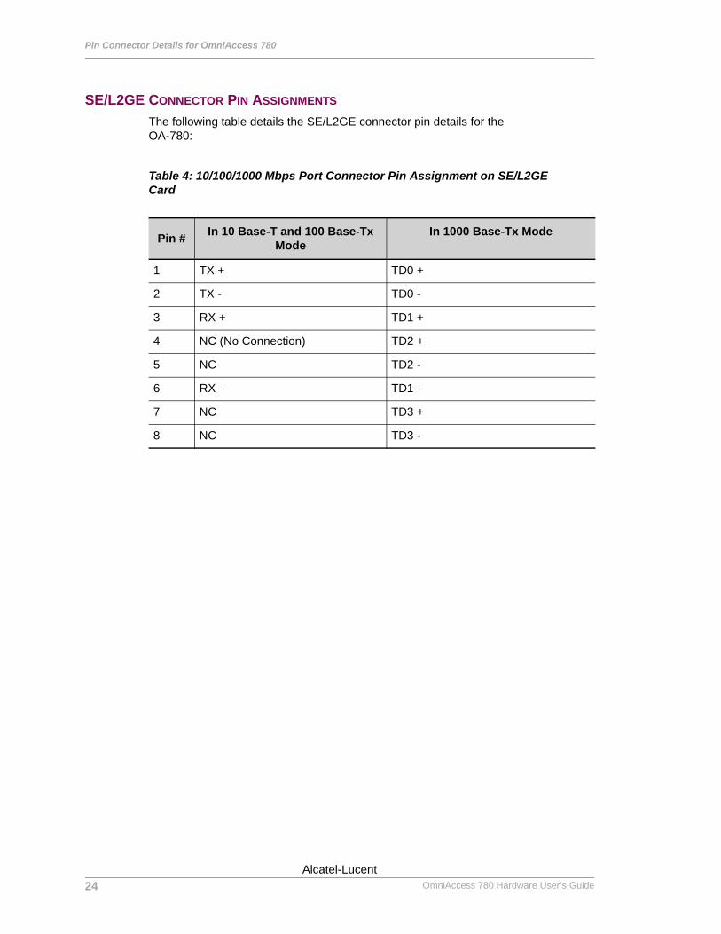
Pin Connector Details for OmniAccess 780
Left running head: Chapter name (automatic)
SE/L2GE CONNECTOR PIN ASSIGNMENTS
The following table details the SE/L2GE connector pin details for the OA-780:
Table 4: 10/100/1000 Mbps Port Connector Pin Assignment on SE/L2GE Card
Pin # In 10 Base-T and 100 Base-Tx Mode
In 1000 Base-Tx Mode
1 TX + TD0 +
2 TX - TD0 -
3 RX + TD1 +
4 NC (No Connection) TD2 +
5 NC TD2 -
6 RX - TD1 -
7 NC TD3 +
8 NC TD3 -
24
Beta BetaOmniAccess 780 Hardware User’s Guide
Alcatel-Lucent
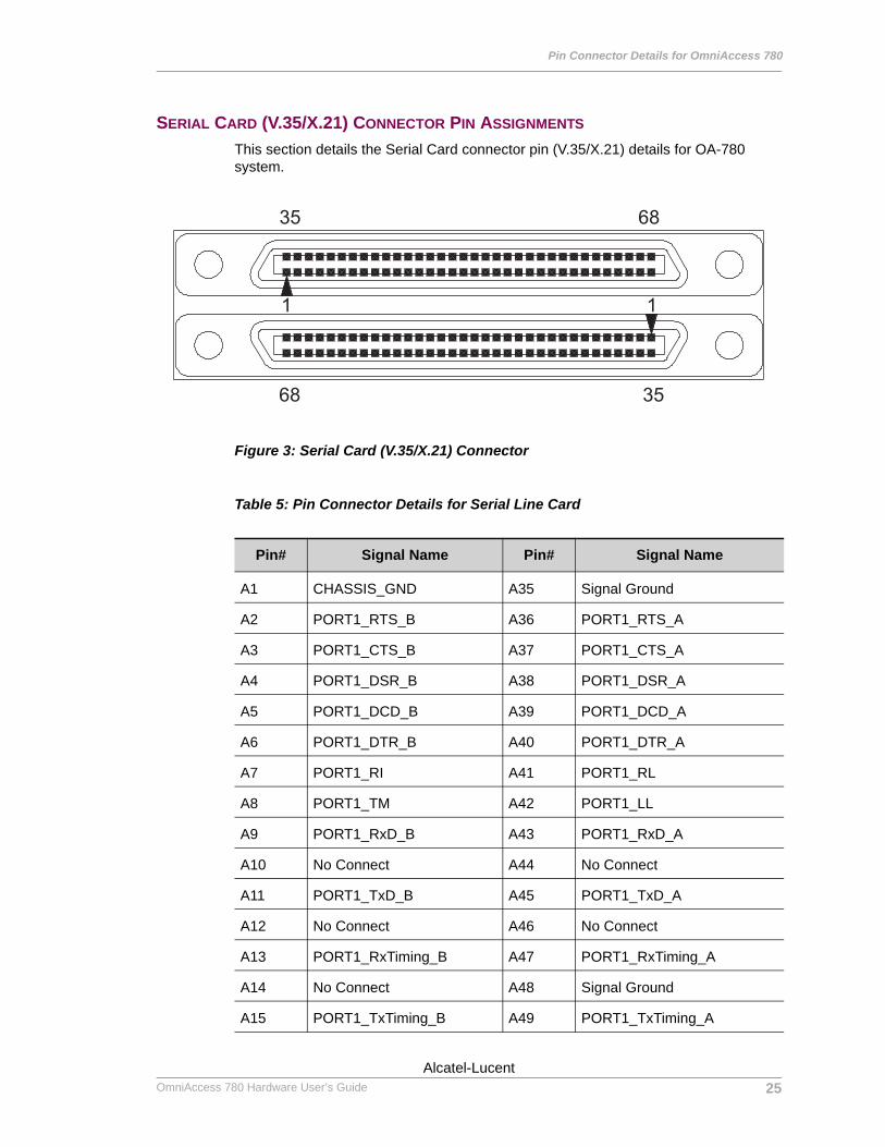
Pin Connector Details for OmniAccess 780
Except on the first page, right running head: Heading1 or Heading1NewPage text (automatic)
SERIAL CARD (V.35/X.21) CONNECTOR PIN ASSIGNMENTS
This section details the Serial Card connector pin (V.35/X.21) details for OA-780 system.
Figure 3: Serial Card (V.35/X.21) Connector
Table 5: Pin Connector Details for Serial Line Card
Pin# Signal Name Pin# Signal Name
A1 CHASSIS_GND A35 Signal Ground
A2 PORT1_RTS_B A36 PORT1_RTS_A
A3 PORT1_CTS_B A37 PORT1_CTS_A
A4 PORT1_DSR_B A38 PORT1_DSR_A
A5 PORT1_DCD_B A39 PORT1_DCD_A
A6 PORT1_DTR_B A40 PORT1_DTR_A
A7 PORT1_RI A41 PORT1_RL
A8 PORT1_TM A42 PORT1_LL
A9 PORT1_RxD_B A43 PORT1_RxD_A
A10 No Connect A44 No Connect
A11 PORT1_TxD_B A45 PORT1_TxD_A
A12 No Connect A46 No Connect
A13 PORT1_RxTiming_B A47 PORT1_RxTiming_A
A14 No Connect A48 Signal Ground
A15 PORT1_TxTiming_B A49 PORT1_TxTiming_A
25Alcatel-Lucent
Beta BetaOmniAccess 780 Hardware User’s Guide
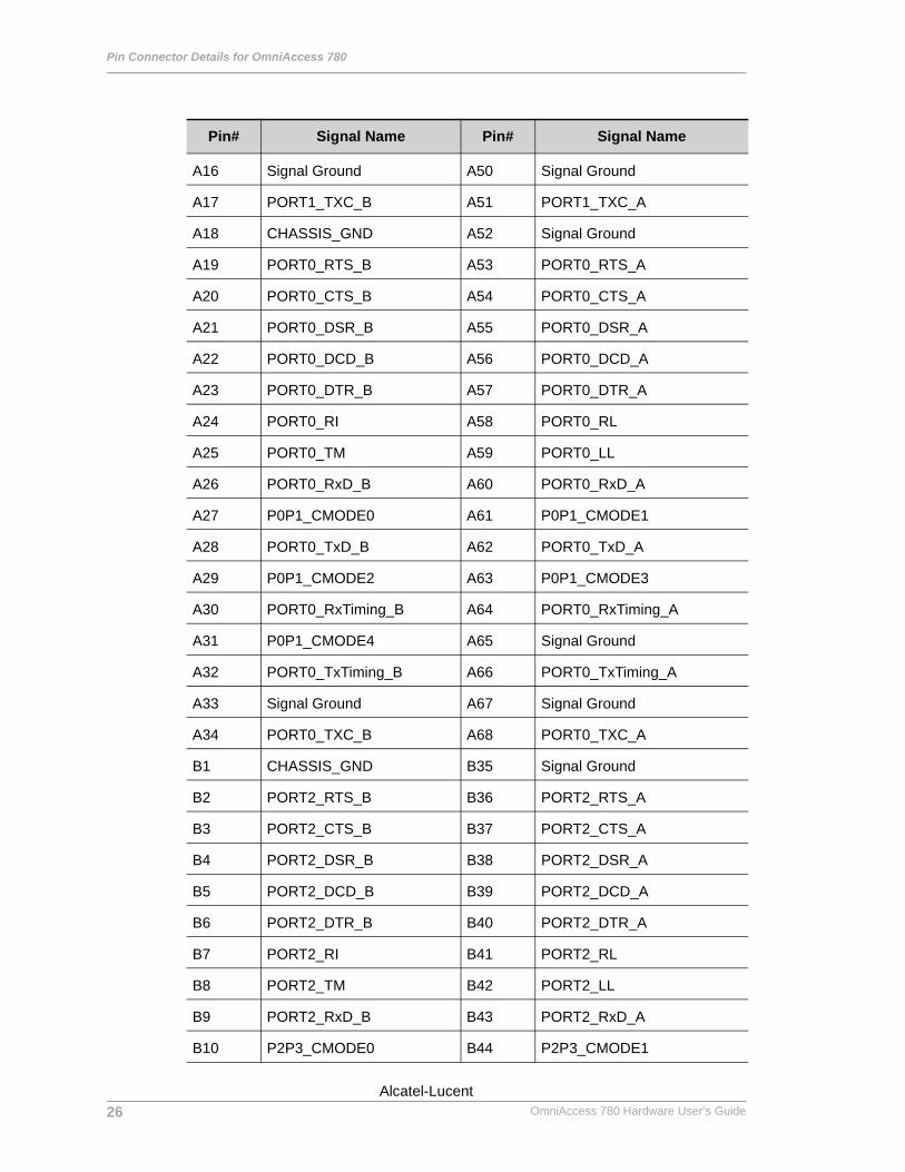
Pin Connector Details for OmniAccess 780
Left running head: Chapter name (automatic)
A16 Signal Ground A50 Signal Ground
A17 PORT1_TXC_B A51 PORT1_TXC_A
A18 CHASSIS_GND A52 Signal Ground
A19 PORT0_RTS_B A53 PORT0_RTS_A
A20 PORT0_CTS_B A54 PORT0_CTS_A
A21 PORT0_DSR_B A55 PORT0_DSR_A
A22 PORT0_DCD_B A56 PORT0_DCD_A
A23 PORT0_DTR_B A57 PORT0_DTR_A
A24 PORT0_RI A58 PORT0_RL
A25 PORT0_TM A59 PORT0_LL
A26 PORT0_RxD_B A60 PORT0_RxD_A
A27 P0P1_CMODE0 A61 P0P1_CMODE1
A28 PORT0_TxD_B A62 PORT0_TxD_A
A29 P0P1_CMODE2 A63 P0P1_CMODE3
A30 PORT0_RxTiming_B A64 PORT0_RxTiming_A
A31 P0P1_CMODE4 A65 Signal Ground
A32 PORT0_TxTiming_B A66 PORT0_TxTiming_A
A33 Signal Ground A67 Signal Ground
A34 PORT0_TXC_B A68 PORT0_TXC_A
B1 CHASSIS_GND B35 Signal Ground
B2 PORT2_RTS_B B36 PORT2_RTS_A
B3 PORT2_CTS_B B37 PORT2_CTS_A
B4 PORT2_DSR_B B38 PORT2_DSR_A
B5 PORT2_DCD_B B39 PORT2_DCD_A
B6 PORT2_DTR_B B40 PORT2_DTR_A
B7 PORT2_RI B41 PORT2_RL
B8 PORT2_TM B42 PORT2_LL
B9 PORT2_RxD_B B43 PORT2_RxD_A
B10 P2P3_CMODE0 B44 P2P3_CMODE1
Pin# Signal Name Pin# Signal Name
26
Beta BetaOmniAccess 780 Hardware User’s Guide
Alcatel-Lucent
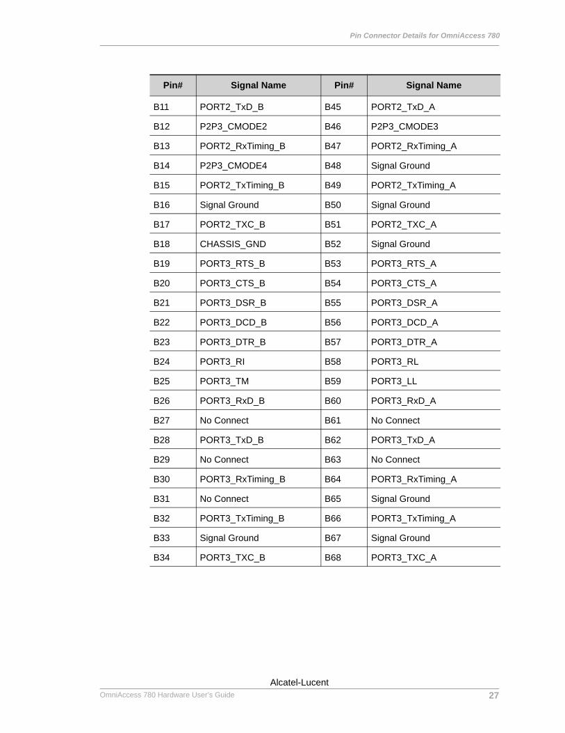
Pin Connector Details for OmniAccess 780
Except on the first page, right running head: Heading1 or Heading1NewPage text (automatic)
B11 PORT2_TxD_B B45 PORT2_TxD_A
B12 P2P3_CMODE2 B46 P2P3_CMODE3
B13 PORT2_RxTiming_B B47 PORT2_RxTiming_A
B14 P2P3_CMODE4 B48 Signal Ground
B15 PORT2_TxTiming_B B49 PORT2_TxTiming_A
B16 Signal Ground B50 Signal Ground
B17 PORT2_TXC_B B51 PORT2_TXC_A
B18 CHASSIS_GND B52 Signal Ground
B19 PORT3_RTS_B B53 PORT3_RTS_A
B20 PORT3_CTS_B B54 PORT3_CTS_A
B21 PORT3_DSR_B B55 PORT3_DSR_A
B22 PORT3_DCD_B B56 PORT3_DCD_A
B23 PORT3_DTR_B B57 PORT3_DTR_A
B24 PORT3_RI B58 PORT3_RL
B25 PORT3_TM B59 PORT3_LL
B26 PORT3_RxD_B B60 PORT3_RxD_A
B27 No Connect B61 No Connect
B28 PORT3_TxD_B B62 PORT3_TxD_A
B29 No Connect B63 No Connect
B30 PORT3_RxTiming_B B64 PORT3_RxTiming_A
B31 No Connect B65 Signal Ground
B32 PORT3_TxTiming_B B66 PORT3_TxTiming_A
B33 Signal Ground B67 Signal Ground
B34 PORT3_TXC_B B68 PORT3_TXC_A
Pin# Signal Name Pin# Signal Name
27Alcatel-Lucent
Beta BetaOmniAccess 780 Hardware User’s Guide

Pin Connector Details for OmniAccess 780
Left running head: Chapter name (automatic)
28
Beta BetaOmniAccess 780 Hardware User’s Guide
Alcatel-Lucent