Embed Size (px)
Citation preview
DediProg Application 10/2017
Application Note:
On-Board IC programming with
DediProg StarProg-ATE Version 1.1
© DediProg Technology Co., Ltd 2017 All Rights Reserved.

Application Note: On-Board IC Programming with DediProg StarProg-ATE
11/2014
www.dediprog.com 2
TABLE OF CONTENTS
I. INTRODUCTION ......................................................................................... 3
1.1 THE ADVANTAGES OF STARPROG-ATE ........................................................................ 3
1.2 FUNCTIONS: .......................................................................................................... 4
1.3 STARPROG-ATE HARDWARE..................................................................................... 4
II. APPLICATIONS ........................................................................................... 7
2.1 INTEGRATE AUTOMATIC PRODUCTION THROUGH THE COMMAND LINE ............................... 7
2.2 PRODUCE THROUGH STARPROG-ATE AND DEDIWARE ................................................... 9
2.3 CREATE A MANUAL FIXTURE TO INTEGRATE WITH STARPROG-ATE ................................... 10
2.4 COMBINE WITH THE SLIDER .................................................................................... 10
2.4.1 Main Procedure: .............................................................................................................. 10
2.4.2 Autorun.bat Procedure .................................................................................................... 11
2.4.3 The hardware connections between StarProg-ATE and the Slider. .................................. 11
2.5 SPECIAL SUPPORT (CUSTOMIZED) ............................................................................ 12
III. CONTROL THROUGH STAND-ALONE AND ATE PORT ........................ 14
3.1 RECOMMENDED CIRCUIT WHEN USING ATE PORT TO CONTROL ..................................... 14
3.2 STAND-ALONE PROCEDURE ..................................................................................... 15
IV. REVISION HISTORY ................................................................................. 16

Application Note: On-Board IC Programming with DediProg StarProg-ATE
11/2014
www.dediprog.com 3
I. Introduction StarProg-ATE is mainly for programming, testing, and firmware upgrading/updating
the ICs that have been welded on the board.
In general, a programmer is designed for a specific IC series, so if users have
demands of programming different types of IC, then they will need to purchase other
kinds of programmers. Since not every programmer is the same, so users will have to
learn new ways of programming, such as how to connect the cable, how to run the
software…etc). It will be more complicated when integrating the programmers with
the automations in a mass production environment.
1.1 The Advantages of StarProg-ATE DediProg developed StarProg-ATE to satisfy different situations for in-circuit programming, which also combined the function of IC programming with automatic production or testing.
Features: Use StarProg-ATE for in-circuit programming. When StarProg-ATE is connected to the
circuit board, it will be able to read and write the corresponding IC.
Advantages: Support various IC kinds from different brands.
Efficient programming speed.
It is able to connect with the automatic systems to program and get the results
of multiple ICs.
Most ICs can support stand-alone programming.
Identical programming software interface and Command Line control.
Requirements: Switch to the corresponding circuit design is required when programming
multiple ICs.
Some IC needs signal isolation design.
Purpose:
A. Provide customer an ease of use programmer that satisfy a variety IC kinds, and
keep it at a low cost.
B. Software updates regularly.
C. No longer need to purchase different programmers and learn different interfaces
for mass production.

Application Note: On-Board IC Programming with DediProg StarProg-ATE
11/2014
www.dediprog.com 4
1.2 Functions:
StarProg-ATE not only provides ICP/ISP programming signals, also allows ATE Port to
integrate with StarProg-ATE and supports stand-alone function.
StarProg-ATE comes with professional software that only need to select the IC model
name, load the file and set up the settings, and then it will be ready for programming.
It also has command line function for integrating with the production software. The
software will proceed to checking and testing after the entire programming process.
Not only through programming software or the command line, StarProg-ATE can
support multiple programmers to process at the same time.
StarProg-ATE has a set of ATE Port; its hardware is designed by the optical coupler for
isolation and protection to control voltage level according to different automatic
systems.
There are four programming control signals (Start, Busy, Pass, and Fail) and eight sets
of project selection signals on StarProg-ATE. Simply by assign a project selection
signal and define the required project file, then it can start programming.
There is a stand-alone function in StarProg-ATE, which allows programming without
connecting to a computer. Simply by choosing the correct IC model, project file and
the settings, and save it in a SD card, plug in the power cable, and then user can start
programming by pressing the start button on the StarProg-ATE or through ATE port.
StarProg-ATE provides these functions, so users can set up according to their
demands and environment to have lean production.
1.3 StarProg-ATE Hardware
The power of StarProg-ATE can be provided by the circuit board during IC
programming, or also directly from StarProg-ATE (However, the power should have
isolation design, please discuss with DediProg).
The isolation design of electric current for providing the power from StarProg-ATE is
to prevent the damages of the IC or the elements on the circuit board.
When integrating automatic testing, there are four extra GPIO for controlling.
Application Note: On-Board IC Programming with DediProg StarProg-ATE
11/2014
www.dediprog.com 5
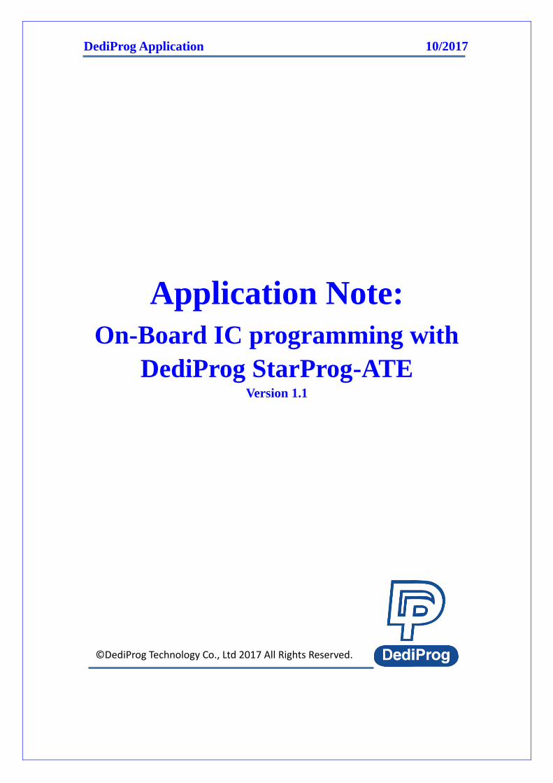
There are three frequently used power output of StarProg-ATE:
VPROG0 (VCC): Provide 1.2V~5.5V voltage output according to the IC,
meanwhile, provide maximum of 500mA electrical current protection.
VPROG1 (Vpp): Provide 5V~16V voltage output according to the IC, meanwhile,
provide maximum of 150mA electrical current protection.
3.3V: Provide 3.3V fixed output voltage.
StarProg-ATE provides a set of 2x10 ICP/ISP Port for connecting to the programming
pins on the circuit board. A 2X7 ATE port is also provided for ATE control.
ICP Port pin definitions
1 CANH 2 VPROG0 (VCC)
3 CANL 4 VPROG1 (Vpp)
5 GND 6 GND
7 3.3V 8 VREF
9 IO7 10 IO8
11 IO5 12 IO6
13 IO3 14 IO4
15 IO1 16 IO2
17 GPIO1 18 GPIO2
19 GPIO3 20 GPIO4
Pin Functions: VPROG0 (VCC): Provide 1.2V~5.5V voltage output according to the IC, meanwhile,
provide maximum of 500mA electrical current protection.
VPROG1 (Vpp) : Provide 5V~16V voltage output according to the IC, meanwhile,
provide maximum of 150mA electrical current protection.
GND: Grounded.
3.3V: A fixed voltage output of 3.3V.
VREF: Reference voltage input. If it detects lack of power, then the programmer will
not respond in order to avoid the damages.
IO1~IO8 (Input/Output): The signal pins (Since different series of ICs have different
definitions, please contact DediProg for more information).
GPIO1~4: The pins that can be controlled separately.
CANH/CANL: CAN bus control (Reserved).

Application Note: On-Board IC Programming with DediProg StarProg-ATE
11/2014
www.dediprog.com 6
ATE Port pin definitions
1 OPTO_GND 2 OPTO_GND
3 SEL0 4 SEL1
5 SEL2 6 Reset
7 OPT_VCC 8 OPT_VCC
9 OPT_Start 10 OPT_Busy
11 OPT_Pass 12 OPT_Fail
13 3.3V 14 GND
ATE Pin Functions: OPTO_GND: ATE signal grounded. Need to be grounded with the automation.
SEL0~2: The control pins for project file selections, which can select up to eight
projects (0~7).
OPT_VCC: VCC voltage input, which requires ATE system to provide electricity
(5V~24V).
OPT_Start: The programmer will switch to low pulse (>1000ms) when it is ready for
operation.
OPT_Busy: Normally stays at low voltage. When the programmer is busy, it will switch
to high voltage, and turn low after finishing.
OPT_Pass: Normally stays at low voltage. It will switch to high voltage when the
programming has completed successfully.
OPT_Fail: Normally stays at low voltage. It will switch to high voltage when error
occurs.
GND: Programmer grounding.
3.3V: Fixed output voltage of 3.3V.
Application Note: On-Board IC Programming with DediProg StarProg-ATE
11/2014
www.dediprog.com 7
II. Applications There are some actual cases clearly explain the applications of StarProg-ATE.
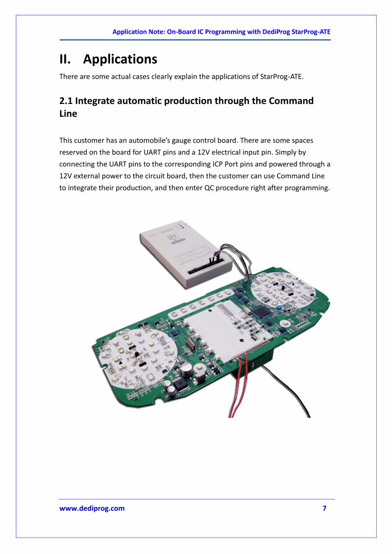
2.1 Integrate automatic production through the Command Line
This customer has an automobile’s gauge control board. There are some spaces
reserved on the board for UART pins and a 12V electrical input pin. Simply by
connecting the UART pins to the corresponding ICP Port pins and powered through a
12V external power to the circuit board, then the customer can use Command Line
to integrate their production, and then enter QC procedure right after programming.
Application Note: On-Board IC Programming with DediProg StarProg-ATE
11/2014
www.dediprog.com 8
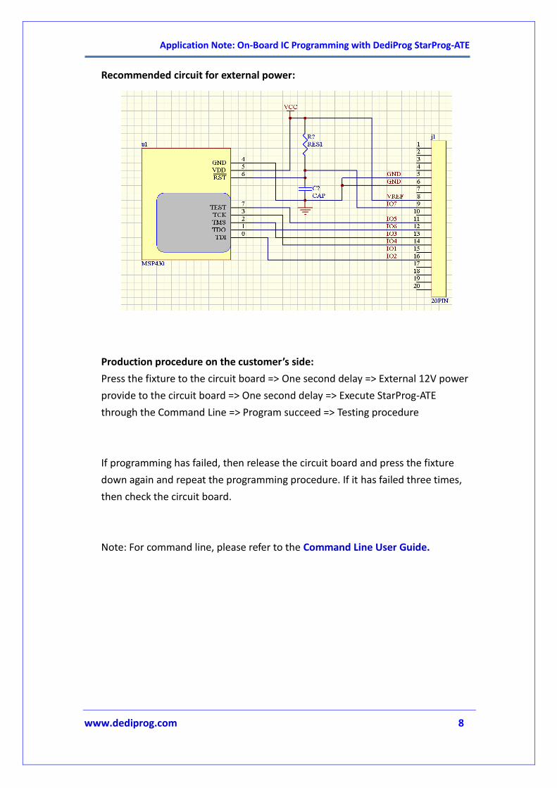
Recommended circuit for external power:
Production procedure on the customer’s side:
Press the fixture to the circuit board => One second delay => External 12V power
provide to the circuit board => One second delay => Execute StarProg-ATE
through the Command Line => Program succeed => Testing procedure
If programming has failed, then release the circuit board and press the fixture
down again and repeat the programming procedure. If it has failed three times,
then check the circuit board.
Note: For command line, please refer to the Command Line User Guide.
Application Note: On-Board IC Programming with DediProg StarProg-ATE
11/2014
www.dediprog.com 9
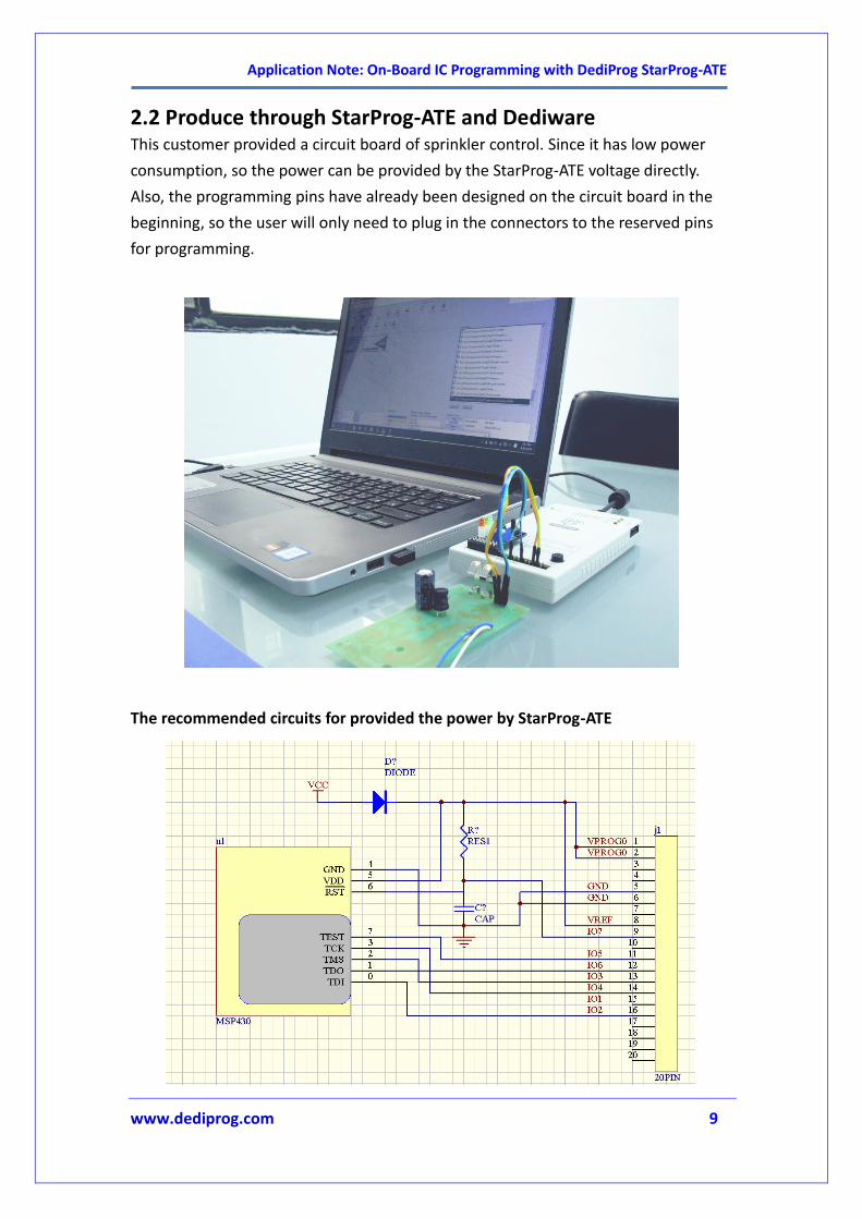
2.2 Produce through StarProg-ATE and Dediware This customer provided a circuit board of sprinkler control. Since it has low power
consumption, so the power can be provided by the StarProg-ATE voltage directly.
Also, the programming pins have already been designed on the circuit board in the
beginning, so the user will only need to plug in the connectors to the reserved pins
for programming.
The recommended circuits for provided the power by StarProg-ATE
Application Note: On-Board IC Programming with DediProg StarProg-ATE
11/2014
www.dediprog.com 10
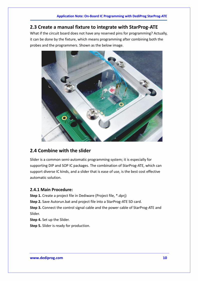
2.3 Create a manual fixture to integrate with StarProg-ATE What if the circuit board does not have any reserved pins for programming? Actually,
it can be done by the fixture, which means programming after combining both the
probes and the programmers. Shown as the below image.
2.4 Combine with the slider
Slider is a common semi-automatic programming system; it is especially for
supporting DIP and SOP IC packages. The combination of StarProg-ATE, which can
support diverse IC kinds, and a slider that is ease of use, is the best cost effective
automatic solution.
2.4.1 Main Procedure: Step 1. Create a project file in Dediware (Project file, *.dprj)
Step 2. Save Autorun.bat and project file into a StarProg-ATE SD card.
Step 3. Connect the control signal cable and the power cable of StarProg-ATE and
Slider.
Step 4. Set up the Slider.
Step 5. Slider is ready for production.

Application Note: On-Board IC Programming with DediProg StarProg-ATE
11/2014
www.dediprog.com 11
2.4.2 Autorun.bat Procedure Create a text file (*.txt) with the contents, and then save as “autorun.bat”.
If there is only one project file, the format should be:
If there are multiple project files, define those files, and then save into a SD card
with autorun.bat file. Select the programming file through SEL0~2 of the ATE
Port.
Warning: Please do not use special characters to name the files, since the
programmer may not be able to recognize the file name.
2.4.3 The hardware connections between StarProg-ATE and the Slider.
The signal definitions of Slider’s connector:
Pin 1 Pin 2 Pin 3 Pin 4 Pin 5 Pin 9
Signals +5VDD VSS Busy Signal OK Signal NG Signal Start Signal
AUTORUN = projectname.dprj
AUTORUN = SEL
0 = projectname1.dprj
1 = projectname2.dprj
2 = projectname3.dprj
3 = projectname4.dprj
4 = projectname5.dprj
5 = projectname6.dprj
Application Note: On-Board IC Programming with DediProg StarProg-ATE
11/2014
www.dediprog.com 12
The ways of connecting the StarProg-ATE and the Slider:
Signal Name ATE Port of StarProg-ATE Slider’s Connector
5V Voltage Pin 7/8 (OPT_VCC) Pin 1
GND Pin 1/2 (OPTO_GND) Pin 2
Start Pin 9 (OPT_Start) Pin 9
Busy Pin 10 (OPT_Busy) Pin 3
Pass Pin 11 (OPT_Pass) Pin 4
Fail Pin 12 (OPT_Fail) Pin 5
Note: External power is required for 5V.
2.4.4 Slider Settings: Set StartSignal as “L”
Set BusySignal as “X”
Set OKSignal as “H”
Set NGSignal as “H”
Set others values according to the production demands.
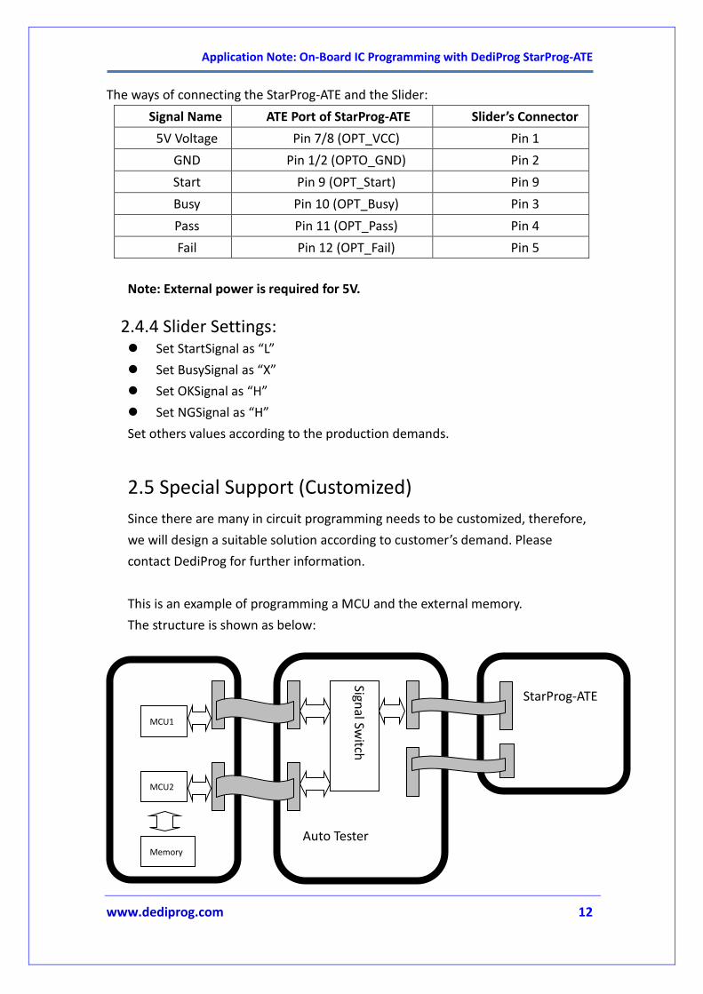
2.5 Special Support (Customized)
Since there are many in circuit programming needs to be customized, therefore,
we will design a suitable solution according to customer’s demand. Please
contact DediProg for further information.
This is an example of programming a MCU and the external memory.
The structure is shown as below:
MCU1
MCU2
Memory
Signal Sw
itch
Auto Tester
StarProg-ATE
Application Note: On-Board IC Programming with DediProg StarProg-ATE
11/2014
www.dediprog.com 13
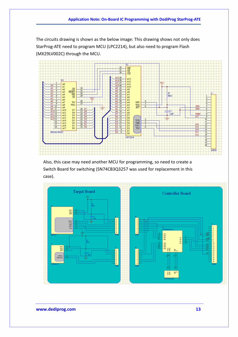
The circuits drawing is shown as the below image: This drawing shows not only does
StarProg-ATE need to program MCU (LPC2214), but also need to program Flash
(MX29LV002C) through the MCU.
Also, this case may need another MCU for programming, so need to create a
Switch Board for switching (SN74CB3Q3257 was used for replacement in this
case).

Application Note: On-Board IC Programming with DediProg StarProg-ATE
11/2014
www.dediprog.com 14
III. Control through Stand-alone and ATE Port
3.1 Recommended circuit when using ATE Port to control
The above diagram shows the simplest design of the ATE Port’s control circuit, which
is beneficial for user to better understand the ATE control.
Since this circuit cannot provide the power independently, therefore, OPT_VCC
connects with 3.3V while OPTO_GND connects with GND.
Connect each OPT_PASS, OPT_BUSY, and OPT_Fail with LCD individually to observe
the signal changes during the operation.
Connect a switch to both OPT_Start and ResetATE individually, since both of them
need Low Pulse to execute.
SEL0~2 needs level signals, so connect the Jumper control signal high or low
separately.

Application Note: On-Board IC Programming with DediProg StarProg-ATE
11/2014
www.dediprog.com 15
3.2 Stand-alone Procedure
Step 1. Shut off the programmer’s power
Step 2. Save the project file (*.dprj) and Autorun.bat into a TF/SD card through card
reader.
Step 3. Insert TF/SD to the programmer.
Step 4. Make sure the circuit of the ATE and the ICP are well connected.
Step 5. Connect the power adapter to the programmer.
Step 6. The Busy light of the StarProg-ATE will start blinking when the programmer is
initializing, and then the light will turn off when the process has completed. The Fail
light will be on if there are some errors, please check the memory card and the
project file.
Step 7. Start ( Press the Start button on the programmer or use the Start through ATE
Port).
Step 8. Execute (The Start Button on the StarProg-ATE is the same has the Start in the
ATE Port.
(1) The output for OPT_Busy will be High while OPT_Pass and OPT_Fail will be
Low. If you use the above recommended diagram, then the LED will be on
when OPT_Busy, and it will turn off when OPT_Pass and OPT_Fail.
(2) After programming is completed, the output of the OPT_Busy will switch to
Low. If the above diagram was used, then the LED will be off.
(3) Meanwhile, one of the OPT_Pass and OPT_Faill will turn on to show the
programming result. If the above diagram was used, then if programming
completed successfully, then the LED of the OPT_Pass will be on. If not,
then the LED of OPT_Fail will be on.
For programming a single file, then you will only need to repeat Step 7 and Step 8. If
there are multiple files to switch, then please follow the below steps:
Step 9. Switch to SEL0~2 condition to select the file that you want to program.
Step 10. Execute a Low pulse to OPT_Reset (More than one second).
Step11. The programmer will be initializing (Back to Step 6).

Application Note: On-Board IC Programming with DediProg StarProg-ATE
11/2014
www.dediprog.com 16
IV. Revision History
Date Version Changes
2016/07/22 1.0 Initial Version.
2017/10/26 1.1 Pin assessment modified.
DediProg Technology Co., Ltd Taiwan Headquarter TEL: 886-2-2790-7932 FAX: 886-2-2790-7916 4F., No.7, Ln. 143, Xinming Rd., Neihu Dist., Taipei City 114, Taiwan
China Office TEL: 86-21-5160-0157
Room 518, Building 66, Lane1333, Xinlong Road, Vanke Hongqiao CBD.Min Hang
District, Shanghai, P.R.C. 201101
U. S. Office TEL: 1-909-274-8860
209 E Baseline RD, Suite E208 #8, Tempe, AZ, 85283, USA
Technical Support: [email protected] Sales Support: [email protected]
Information furnished is believed to be accurate and reliable. However, DediProg
assumes no responsibility for the consequences of use of such information or for any
infringement of patents or other rights of third parties which may result from its use.
Specifications mentioned in this publication are subject to change without notice.
This publication supersedes and replaces all information previously supplied.
All rights reserved
Printed in Taiwan.