Embed Size (px)
Citation preview

On-line quality assurance of rotational radiotherapy treatment deliveryby means of a 2D ion chamber array and the Octavius phantom
Ann Van Escha�
Clinique Ste Elisabeth, Place L. Godin 15, 5000 Namur, Belgiumand 7Sigma, Kasteeldreef 2, 3150 Tildonk, Belgium
Christian Clermont and Magali DevillersClinique Ste Elisabeth, Place L. Godin 15, 5000 Namur, Belgium
Mauro IoriSanta Maria Nuova Hospital, Viale Risorgimento 80, 42100 Reggio Emilia, Italy
Dominique P. HuyskensClinique Ste Elisabeth, Place L. Godin 15, 5000 Namur, Belgiumand 7Sigma, Kasteeldreef 2, 3150 Tildonk, Belgium
�Received 25 February 2007; revised 3 June 2007; accepted for publication 7 August 2007;published 17 September 2007�
For routine pretreatment verification of innovative treatment techniques such as �intensity modu-lated� dynamic arc therapy and helical TomoTherapy, an on-line and reliable method would behighly desirable. The present solution proposed by TomoTherapy, Inc. �Madison, WI� relies on filmdosimetry in combination with up to two simultaneous ion chamber point dose measurements. Anew method is proposed using a 2D ion chamber array �Seven29, PTW, Freiburg, Germany�inserted in a dedicated octagonal phantom, called Octavius. The octagonal shape allows easypositioning for measurements in multiple planes. The directional dependence of the response of thedetector was primarily investigated on a dual energy �6 and 18 MV� Clinac 21EX �Varian MedicalSystems, Palo Alto, CA� as no fixed angle incidences can be calculated in the Hi-Art TPS ofTomoTherapy. The array was irradiated from different gantry angles and with different arc deliv-eries, and the dose distributions at the level of the detector were calculated with the AAA �Ana-lytical Anisotropic Algorithm� photon dose calculation algorithm implemented in Eclipse �Varian�.For validation on the 6 MV TomoTherapy unit, rotational treatments were generated, and dosedistributions were calculated with the Hi-Art TPS. Multiple cylindrical ion chamber measurementswere used to cross-check the dose calculation and dose delivery in Octavius in the absence of the2D array. To compensate for the directional dependence of the 2D array, additional prototypes ofOctavius were manufactured with built-in cylindrically symmetric compensation cavities. Whenusing the Octavius phantom with a 2 cm compensation cavity, measurements with an accuracycomparable to that of single ion chambers can be achieved. The complete Octavius solution forquality assurance of rotational treatments consists of: The 2D array, two octagonal phantoms �withand without compensation layer�, an insert for nine cylindrical ion chambers, and a set of inserts ofvarious tissue equivalent materials of different densities. The combination of the 2D array with theOctavius phantom proved to be a fast and reliable method for pretreatment verification of rotationaltreatments. Quality control of TomoTherapy patients was reduced to a total of �25 min perpatient. © 2007 American Association of Physicists in Medicine. �DOI: 10.1118/1.2777006�
Key words: dynamic arc, tomotherapy, quality assurance
I. INTRODUCTION
Along with the rising interest in rotational radiotherapy treat-ments comes the need for appropriate and efficient qualityassurance �QA� solutions. Although intensity modulated arctherapy �IMAT� using all-round linear accelerators has beenapplied for many years now,1–8 its use has mostly been re-stricted to academic centers having developed their in-housesolution for the planning as well as for the QA. In general, aphantom approach is used for the treatment verification: Thetreatment plan is transferred onto a phantom, and the dose isrecalculated for this phantom setup. Measurements are per-
9–12
formed mostly with film �radiographic or radiochromic�3825 Med. Phys. 34 „10…, October 2007 0094-2405/2007/34„1
and ion chamber point dose measurements.13 Gel dosimetrywas also shown to be of interest.14,15 With the commercialavailability of the helical TomoTherapy solution,16–20 the ro-tational IMRT treatments are becoming available to a widerrange of radiotherapy centers. Many of these, however, lackthe time and personnel for time consuming patient specificQA. As the rotational treatments are still innovative and suf-fering from growing pains, patient specific QA remains ad-visory and the need for fast and reliable QA tools is thereforeimminent. TomoTherapy includes a QA package within theirtreatment solution,21–23 relying on film dosimetry in combi-
nation with up to two simultaneous ion chamber point dose38250…/3825/13/$23.00 © 2007 Am. Assoc. Phys. Med.

3826 Van Esch et al.: On-line quality assurance of rotational radiotherapy 3826
measurements. Although film dosimetry is a valuable, wellestablished QA method when performed correctly, its reli-ability heavily depends on the constancy of external param-eters such as the quality of the dark room and the stability ofthe film developer and on the possibility to correct for arti-facts related to the scanner. Because of the increased use ofdigital imaging in radiology and radiotherapy, well moni-tored, stable film developers are becoming more and moredifficult to find in the average hospital environment. Thecircular phantom—referred to as the Cheese phantom—designed for TomoTherapy QA purposes has a length of18 cm, which is not sufficient to cover most head and necktreatment plans within one verification setup. For machineQA, the TomoDOSE diode array �Sun Nuclear, Melbourne,FL� can be purchased to provide on-line data on the repro-ducibility of the beam profiles in static gantry mode,24 but itcannot be used for TPS validation or patient pretreatmentverification.
Portal dosimetry remains by far the most time efficientpretreatment verification method for fixed gantry IMRT treat-ments, provided it is fully integrated in the used IMRTsolution.25–27 Although it is not yet commercially availablefor �intensity modulated� dynamic arc treatments, in theory,both the image acquisition and prediction should be verysimilar to the fixed gantry portal dosimetry solution. No por-tal imager is available on the TomoTherapy treatment unit,but the linear detector array used for the acquisition of theMV-CT could potentially be used for measuring the dosedelivery during irradiation. However, both image acquisitionmodalities show the considerable disadvantage that they ro-tate along with the treatment beam and will therefore notinclude any angular information in their data acquisition. Inextremis, should the treatment beam not rotate at all duringdelivery, this will go undetected in the portal image acquisi-tion. Although portal dosimetry may eventually be part of aQA solution including additional monitoring of the gantryangle, pretreatment verification in a phantom remains themost complete verification method for now.
In order to replace the film measurement with a lesstroublesome, absolute and preferably on-line 2D dose mea-surement method, the applicability of the Seven29 �PTW,Freiburg, Germany� 2D ion chamber array28,29 was investi-gated. In addition, a multipurpose phantom was developed toovercome some of the disadvantages of the Cheese phantomwhile accommodating for the use of the ion chamber array inmultiple measurement planes. The Seven29/Octavius combi-nation was validated for use on a Clinac as well as on ahelical TomoTherapy treatment unit.
II. MATERIAL AND METHODS
Although the goal of the study is to use the detector dur-ing any kind of dynamic rotational treatment to investigateits directional dependence, most of the initial tests were per-formed by means of static fields and simple arc treatments ona dual energy �6 and 18 MV� linear accelerator Clinac 21EX
�Varian Medical Systems, Palo Alto, CA�. It was then veri-Medical Physics, Vol. 34, No. 10, October 2007
fied if the data obtained on the TomoTherapy 6 MV treat-ment unit were consistent with that obtained on the Clinac.
Following its validation, the newly developed QA proce-dure was tested on a number of dynamic arc and Tomo-Therapy patients.
II.A. The Octavius phantom
A dedicated phantom was constructed for the QA of rota-tional treatments focusing primarily on the use of theSeven29 �PTW, Freiburg, Germany� 2D ion chamber array,but also allowing individual ion chamber measurements. Anoctagonal shape was chosen to allow data acquisition in mul-tiple planes with an easy phantom setup. The phantom iscalled Octavius and is made of polystyrene �physical density1.04 g/cm3, relative electron density 1.00�. It is 32 cm wideand has a length of 32 cm. A 30�30�2.2 cm3 central cavityallows the user to insert the 2D ion chamber array into thephantom �Fig. 1�a��. The position of the cavity is such thatwhen the 2D array is inserted, the plane through the middleof the ion chambers goes through the center of the phantom.For the single ion chamber measurements, three separateslabs of 10�31�2.2 cm3 were constructed �Fig. 1�c��, twoof which are entirely solid whereas the third slab containsnine ion chamber inserts with a center to center spacing of1.05 cm and a diameter of 0.69 cm to accommodate for0.125 cc thimble chambers �T31010 Semiflex, PTW,Freiburg, Germany�. The nine thimble chambers can be readout simultaneously by means of the Multidose electrometer�PTW, Freiburg, Germany� equipped with a connector box.
In addition, inserts of different tissue equivalent materials
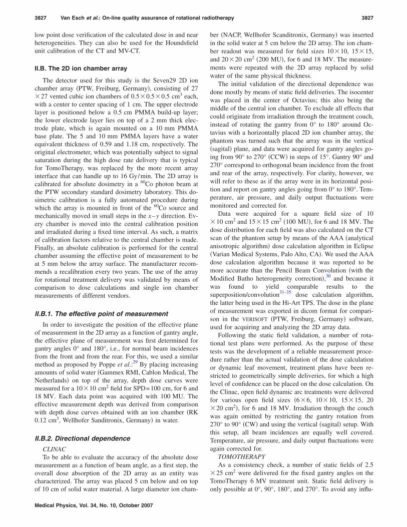
FIG. 1. Different configurations of the Octavius phantom: �a� OctaviusCT-IC
with 2D array for dose calculation in different planes of measurement, �b�Octavius729/2D array tandem for measurements, �c� OctaviusCT-IC with mul-tiple ion chamber insert, and �d� OctaviusCT-IC with heterogeneous inserts.
�Barts and The London NHS Trust, London� �Fig. 1�d�� al-
3827 Van Esch et al.: On-line quality assurance of rotational radiotherapy 3827
low point dose verification of the calculated dose in and nearheterogeneities. They can also be used for the Houndsfieldunit calibration of the CT and MV-CT.
II.B. The 2D ion chamber array
The detector used for this study is the Seven29 2D ionchamber array �PTW, Freiburg, Germany�, consisting of 27�27 vented cubic ion chambers of 0.5�0.5�0.5 cm3 each,with a center to center spacing of 1 cm. The upper electrodelayer is positioned below a 0.5 cm PMMA build-up layer;the lower electrode layer lies on top of a 2 mm thick elec-trode plate, which is again mounted on a 10 mm PMMAbase plate. The 5 and 10 mm PMMA layers have a waterequivalent thickness of 0.59 and 1.18 cm, respectively. Theoriginal electrometer, which was potentially subject to signalsaturation during the high dose rate delivery that is typicalfor TomoTherapy, was replaced by the more recent arrayinterface that can handle up to 16 Gy/min. The 2D array iscalibrated for absolute dosimetry in a 60Co photon beam atthe PTW secondary standard dosimetry laboratory. This do-simetric calibration is a fully automated procedure duringwhich the array is mounted in front of the 60Co source andmechanically moved in small steps in the x–y direction. Ev-ery chamber is moved into the central calibration positionand irradiated during a fixed time interval. As such, a matrixof calibration factors relative to the central chamber is made.Finally, an absolute calibration is performed for the centralchamber assuming the effective point of measurement to beat 5 mm below the array surface. The manufacturer recom-mends a recalibration every two years. The use of the arrayfor rotational treatment delivery was validated by means ofcomparison to dose calculations and single ion chambermeasurements of different vendors.
II.B.1. The effective point of measurement
In order to investigate the position of the effective planeof measurement in the 2D array as a function of gantry angle,the effective plane of measurement was first determined forgantry angles 0° and 180°, i.e., for normal beam incidencesfrom the front and from the rear. For this, we used a similarmethod as proposed by Poppe et al.:29 By placing increasingamounts of solid water �Gammex RMI, Cablon Medical, TheNetherlands� on top of the array, depth dose curves weremeasured for a 10�10 cm2 field for SPD=100 cm, for 6 and18 MV. Each data point was acquired with 100 MU. Theeffective measurement depth was derived from comparisonwith depth dose curves obtained with an ion chamber �RK0.12 cm3, Wellhofer Sanditronix, Germany� in water.
II.B.2. Directional dependence
CLINACTo be able to evaluate the accuracy of the absolute dose
measurement as a function of beam angle, as a first step, theoverall dose absorption of the 2D array as an entity wascharacterized. The array was placed 5 cm below and on top
of 10 cm of solid water material. A large diameter ion cham-Medical Physics, Vol. 34, No. 10, October 2007
ber �NACP, Wellhofer Scanditronix, Germany� was insertedin the solid water at 5 cm below the 2D array. The ion cham-ber readout was measured for field sizes 10�10, 15�15,and 20�20 cm2 �200 MU�, for 6 and 18 MV. The measure-ments were repeated with the 2D array replaced by solidwater of the same physical thickness.
The initial validation of the directional dependence wasdone mostly by means of static field deliveries. The isocenterwas placed in the center of Octavius; this also being themiddle of the central ion chamber. To exclude all effects thatcould originate from irradiation through the treatment couch,instead of rotating the gantry from 0° to 180° around Oc-tavius with a horizontally placed 2D ion chamber array, thephantom was turned such that the array was in the vertical�sagital� plane, and data were acquired for gantry angles go-ing from 90° to 270° �CCW� in steps of 15°. Gantry 90° and270° correspond to orthogonal beam incidence from the frontand rear of the array, respectively. For clarity, however, wewill refer to these as if the array were in its horizontal posi-tion and report on gantry angles going from 0° to 180°. Tem-perature, air pressure, and daily output fluctuations weremonitored and corrected for.
Data were acquired for a square field size of 10�10 cm2 and 15�15 cm2 �100 MU�, for 6 and 18 MV. Thedose distribution for each field was also calculated on the CTscan of the phantom setup by means of the AAA �analyticalanisotropic algorithm� dose calculation algorithm in Eclipse�Varian Medical Systems, Palo Alto, CA�. We used the AAAdose calculation algorithm because it was reported to bemore accurate than the Pencil Beam Convolution �with theModified Batho heterogeneity correction�,30 and because itwas found to yield comparable results to thesuperposition/convolution31–35 dose calculation algorithm,the latter being used in the Hi-Art TPS. The dose in the planeof measurement was exported in dicom format for compari-son in the VERISOFT �PTW, Freiburg, Germany� software,used for acquiring and analyzing the 2D array data.
Following the static field validation, a number of rota-tional test plans were performed. As the purpose of thesetests was the development of a reliable measurement proce-dure rather than the actual validation of the dose calculationor dynamic leaf movement, treatment plans have been re-stricted to geometrically simple deliveries, for which a highlevel of confidence can be placed on the dose calculation. Onthe Clinac, open field dynamic arc treatments were deliveredfor various open field sizes �6�6, 10�10, 15�15, 20�20 cm2�, for 6 and 18 MV. Irradiation through the couchwas again omitted by restricting the gantry rotation from270° to 90° �CW� and using the vertical �sagital� setup. Withthis setup, all beam incidences are equally well covered.Temperature, air pressure, and daily output fluctuations wereagain corrected for.
TOMOTHERAPYAs a consistency check, a number of static fields of 2.5
�25 cm2 were delivered for the fixed gantry angles on theTomoTherapy 6 MV treatment unit. Static field delivery is
only possible at 0°, 90°, 180°, and 270°. To avoid any influ-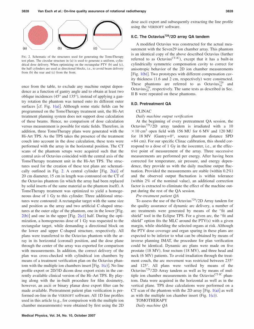
3828 Van Esch et al.: On-line quality assurance of rotational radiotherapy 3828
ence from the table, to exclude any machine output depen-dence as a function of gantry angle and to obtain at least twooblique incidences �45° and 135°�, instead of applying a gan-try rotation the phantom was turned onto its different outersurfaces �cf. Fig. 1�a��. Although some static fields can beprogrammed on the TomoTherapy treatment unit, the Hi-Arttreatment planning system does not support dose calculationof these beams. Hence, no comparison of dose calculationversus measurement is possible for static fields. Therefore, inaddition, three TomoTherapy plans were generated with theHi-Art TPS. As the TPS takes the presence of the treatmentcouch into account in the dose calculation, these tests wereperformed with the array in the horizontal position. The CTscans of the phantom setups were acquired such that thecentral axis of Octavius coincided with the central axis of theTomoTherapy treatment unit in the Hi-Art TPS. The struc-tures used for the creation of these test plans are schemati-cally outlined in Fig. 2. A central cylinder �Fig. 2�a�� of20 cm diameter, 15 cm in length was contoured on the CT ofthe Octavius phantom �in which the array had been replacedby solid inserts of the same material as the phantom itself�. ATomoTherapy treatment was optimized to yield a homoge-neous dose of 1 Gy to this cylinder. Three additional struc-tures were contoured: A rectangular target with the same sizeand position as the array and two artificial C-shaped struc-tures at the outer edge of the phantom, one in the lower �Fig.2�b�� and one in the upper �Fig. 2�c�� half. During the opti-mization, a homogeneous dose of 1 Gy was requested to therectangular target, while demanding a directional block onthe lower and upper C-shaped structure, respectively. Allplans were transferred to the Octavius phantom with the ar-ray in its horizontal �coronal� position, and the dose planethrough the center of the array was exported for comparisonwith measurements. In addition, the correct delivery of theplan was cross-checked with cylindrical ion chambers bymeans of a treatment verification plan on the Octavius phan-tom with the multiple ion chambers insert �Fig. 1�c��. No lineprofile export or 2D/3D dicom dose export exists in the cur-rently available clinical version of the Hi–Art TPS. By play-ing along with the in–built procedure for film dosimetry,however, an ascii or binary planar dose export filter can bemade available. Pretreatment patient plan verification is per-formed on-line in the VERISOFT software. All 1D line profilesused in this article �e.g., for comparison with the multiple ion
FIG. 2. Schematic of the structures used for generating the TomoTherapytest plans. The circular structure in �a� is used to generate a uniform, cylin-drical dose delivery. When optimizing on the rectangular PTV �b� and �c�,the half cylinders are used as directional blocks, i.e., to avoid beam deliveryfrom �b� the rear and �c� from the front.
chamber measurements� were obtained by first using the 2D
Medical Physics, Vol. 34, No. 10, October 2007
dose ascii export and subsequently extracting the line profileusing the VERISOFT software.
II.C. The Octavius729/2D array QA tandem
A modified Octavius was constructed for the actual mea-surement with the Seven29 ion chamber array. This phantomis an identical copy of the above described Octavius �furtherreferred to as OctaviusCT-IC�, except that it has a built-incylindrically symmetric compensation cavity to correct foranisotropic behavior of the 2D ion chamber measurements�Fig. 1�b��. Two prototypes with different compensation cav-ity thickness �1.6 and 2 cm, respectively� were constructed.These phantoms are referred to as Octavius16
729 andOctavius20
729, respectively. The same tests as described in Sec.II B were repeated on these phantoms.
II.D. Pretreatment QA
CLINACDaily machine output verificationAt the beginning of every pretreatment QA session, the
Octavius729/2D array tandem is irradiated with a 10�10 cm2 open field with 156 MU for 6 MV and 120 MUfor 18 MV �Gantry=0°, source phantom distance SPD=84 cm�. For our specific Clinac calibration, this should cor-respond to a dose of 1 Gy in the isocenter, i.e., at the effec-tive point of measurement of the array. Three successivemeasurements are performed per energy. After having beencorrected for temperature, air pressure, and energy depen-dence, they provide us with the daily machine output fluc-tuation. Provided the measurements are stable �within 0.2%�and the observed output fluctuation is within tolerance�within 2% of the nominal value�, an additional correctionfactor is extracted to eliminate the effect of the machine out-put during the rest of the QA session.
Pre-treatment patient QATo assess the use of the Octavius729/2D Array tandem for
the quality assurance of dynamic arc delivery, a number ofarc treatments were generated by means of the “fit andshield” tool in the Eclipse TPS. For a given arc, the “fit andshield” option fits the MLC around the PTV�s� with a givenmargin, while shielding the selected organs at risk. Althoughthe PTV dose coverage and organ sparing in these plans areexpected to be inferior to what can be obtained by means ofinverse planning IMAT, the procedure for plan verificationcould be identical. Dynamic arc plans were made on fiveprostate �18 MV�, four rectum �18 MV�, and three head andneck �6 MV� patients. To avoid irradiation through the treat-ment couch, the arc movement was restricted between 235°and 125°. All plans were verified by means of theOctavius729/2D Array tandem as well as by means of mul-tiple ion chamber measurements in the OctaviusCT-IC phan-tom. Data were acquired in the horizontal as well as in thevertical plane. TPS dose calculations were performed on aCT scan of the phantom with the 2D array �Fig. 1�a�� as wellas with the multiple ion chamber insert �Fig. 1�c��.
TOMOTHERAPY
Daily machine QA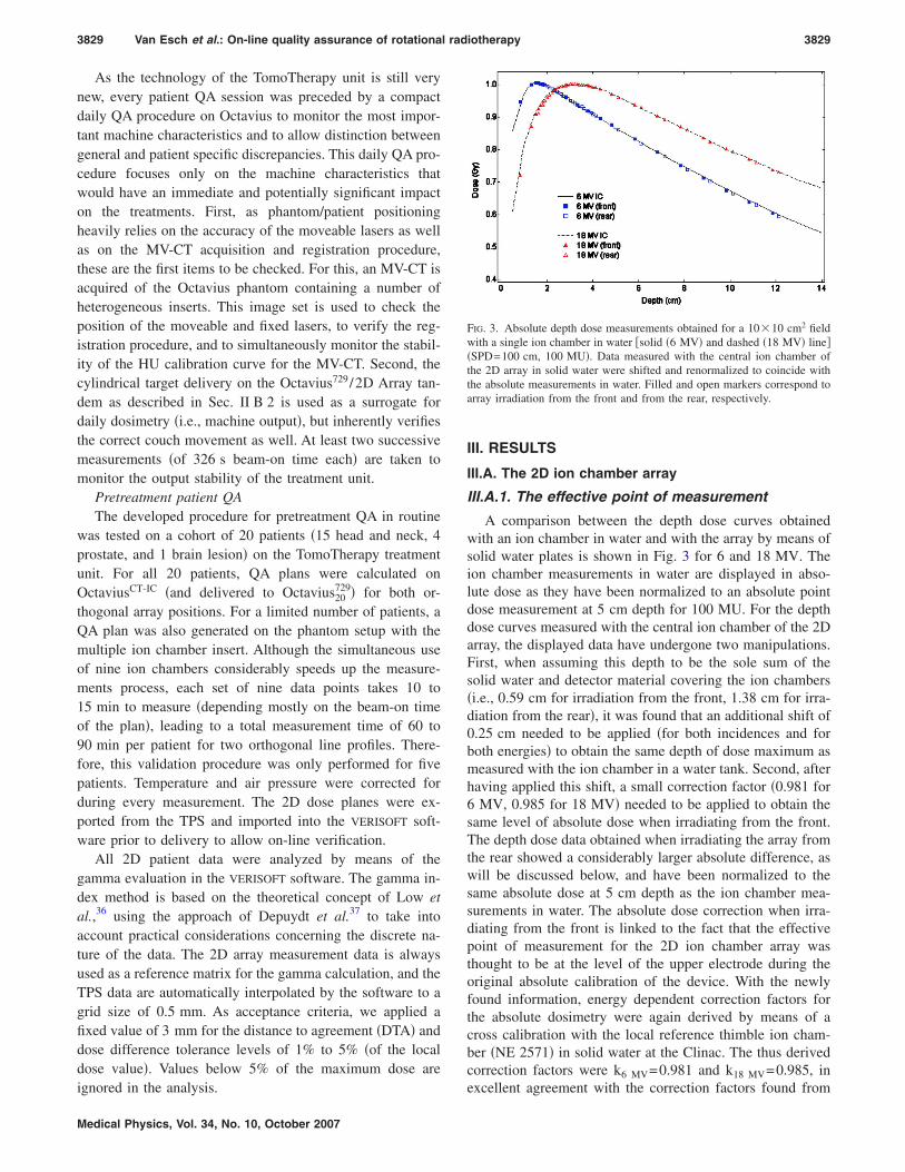
3829 Van Esch et al.: On-line quality assurance of rotational radiotherapy 3829
As the technology of the TomoTherapy unit is still verynew, every patient QA session was preceded by a compactdaily QA procedure on Octavius to monitor the most impor-tant machine characteristics and to allow distinction betweengeneral and patient specific discrepancies. This daily QA pro-cedure focuses only on the machine characteristics thatwould have an immediate and potentially significant impacton the treatments. First, as phantom/patient positioningheavily relies on the accuracy of the moveable lasers as wellas on the MV-CT acquisition and registration procedure,these are the first items to be checked. For this, an MV-CT isacquired of the Octavius phantom containing a number ofheterogeneous inserts. This image set is used to check theposition of the moveable and fixed lasers, to verify the reg-istration procedure, and to simultaneously monitor the stabil-ity of the HU calibration curve for the MV-CT. Second, thecylindrical target delivery on the Octavius729/2D Array tan-dem as described in Sec. II B 2 is used as a surrogate fordaily dosimetry �i.e., machine output�, but inherently verifiesthe correct couch movement as well. At least two successivemeasurements �of 326 s beam-on time each� are taken tomonitor the output stability of the treatment unit.
Pretreatment patient QAThe developed procedure for pretreatment QA in routine
was tested on a cohort of 20 patients �15 head and neck, 4prostate, and 1 brain lesion� on the TomoTherapy treatmentunit. For all 20 patients, QA plans were calculated onOctaviusCT-IC �and delivered to Octavius20
729� for both or-thogonal array positions. For a limited number of patients, aQA plan was also generated on the phantom setup with themultiple ion chamber insert. Although the simultaneous useof nine ion chambers considerably speeds up the measure-ments process, each set of nine data points takes 10 to15 min to measure �depending mostly on the beam-on timeof the plan�, leading to a total measurement time of 60 to90 min per patient for two orthogonal line profiles. There-fore, this validation procedure was only performed for fivepatients. Temperature and air pressure were corrected forduring every measurement. The 2D dose planes were ex-ported from the TPS and imported into the VERISOFT soft-ware prior to delivery to allow on-line verification.
All 2D patient data were analyzed by means of thegamma evaluation in the VERISOFT software. The gamma in-dex method is based on the theoretical concept of Low etal.,36 using the approach of Depuydt et al.37 to take intoaccount practical considerations concerning the discrete na-ture of the data. The 2D array measurement data is alwaysused as a reference matrix for the gamma calculation, and theTPS data are automatically interpolated by the software to agrid size of 0.5 mm. As acceptance criteria, we applied afixed value of 3 mm for the distance to agreement �DTA� anddose difference tolerance levels of 1% to 5% �of the localdose value�. Values below 5% of the maximum dose are
ignored in the analysis.Medical Physics, Vol. 34, No. 10, October 2007
III. RESULTS
III.A. The 2D ion chamber array
III.A.1. The effective point of measurement
A comparison between the depth dose curves obtainedwith an ion chamber in water and with the array by means ofsolid water plates is shown in Fig. 3 for 6 and 18 MV. Theion chamber measurements in water are displayed in abso-lute dose as they have been normalized to an absolute pointdose measurement at 5 cm depth for 100 MU. For the depthdose curves measured with the central ion chamber of the 2Darray, the displayed data have undergone two manipulations.First, when assuming this depth to be the sole sum of thesolid water and detector material covering the ion chambers�i.e., 0.59 cm for irradiation from the front, 1.38 cm for irra-diation from the rear�, it was found that an additional shift of0.25 cm needed to be applied �for both incidences and forboth energies� to obtain the same depth of dose maximum asmeasured with the ion chamber in a water tank. Second, afterhaving applied this shift, a small correction factor �0.981 for6 MV, 0.985 for 18 MV� needed to be applied to obtain thesame level of absolute dose when irradiating from the front.The depth dose data obtained when irradiating the array fromthe rear showed a considerably larger absolute difference, aswill be discussed below, and have been normalized to thesame absolute dose at 5 cm depth as the ion chamber mea-surements in water. The absolute dose correction when irra-diating from the front is linked to the fact that the effectivepoint of measurement for the 2D ion chamber array wasthought to be at the level of the upper electrode during theoriginal absolute calibration of the device. With the newlyfound information, energy dependent correction factors forthe absolute dosimetry were again derived by means of across calibration with the local reference thimble ion cham-ber �NE 2571� in solid water at the Clinac. The thus derivedcorrection factors were k6 MV=0.981 and k18 MV=0.985, in
FIG. 3. Absolute depth dose measurements obtained for a 10�10 cm2 fieldwith a single ion chamber in water �solid �6 MV� and dashed �18 MV� line��SPD=100 cm, 100 MU�. Data measured with the central ion chamber ofthe 2D array in solid water were shifted and renormalized to coincide withthe absolute measurements in water. Filled and open markers correspond toarray irradiation from the front and from the rear, respectively.
excellent agreement with the correction factors found from
3830 Van Esch et al.: On-line quality assurance of rotational radiotherapy 3830
the depth dose behavior. This calibration correction wastaken into account for all further measurements.
III.A.2. Directional dependence
CLINACThe absolute dose measured in the solid water at 5 cm
below the array was within 1.5% of the absolute dose mea-sured in the same configuration but with the array replacedby a 2.2 cm solid water slab, showing that the overall doseabsorption of the array is near water equivalent.
The directional dependence of the 2D ion chamber arraycan be observed in Fig. 4�a�, showing the measured and cal-culated profiles for a 10�10 cm2 field for a number of gan-try angles �gantry 0°, 30°, 60°, 90°, 120°, 150°, and 180°�.Figure 4�b� shows the percentage dose difference on thebeam axis as a function of gantry angle. When the array isirradiated from the front, agreement between TPS and mea-surement is within 1.0% on the beam axis and within 2%,2 mm over the whole measured surface, for both energies,even for highly oblique incidences. However, when the beamincidence moves to the rear of the array, a considerable ab-solute deviation becomes apparent. When measured and cal-culated data are both normalized to their value on the beamaxis, agreement is restored to within 2%, 2 mm. Apart froma narrow transition period for gantry angles between 75° and105°, the percentage dose difference quickly saturates ontothe constant value of 4% for 18 MV and 8% for 6 MV.Whereas the TPS is predicting only slight differences be-tween the absorbed doses for mirrored beam angles �e.g., 45°and 135°�, measurements for gantry angles between 90° and180° show a considerably smaller signal. Very similar resultsto the ones displayed in Fig. 4 were obtained for the otherfield sizes: All showed a relative overall agreement of 2%,2 mm when normalized to the beam axis and a percentagedose difference as displayed in Fig. 4�b�.
For all field sizes, the correct delivery of the half-arc openfield treatment was confirmed by means of the multiple ionchamber measurements �Fig. 5�. There is a noticeable differ-ence between the dose calculation on the OctaviusCT-IC phan-tom with the 2D array and with the multiple ion chamberinsert because of their different structure and average density.Separate dose calculations for both setups are therefore re-quired. For the multiple ion chamber measurements, intheory, the dose should be recalculated for all three possiblepositions of the ion chamber insert. We have, however, per-formed only a single dose calculation on the phantom withthe insert in its central position. From Fig. 5, it appears thatthis is an adequate approximation for the overall line profilecalculation during arc delivery. Knowing the arc delivery tobe correct, in Fig. 5 we observe that the array measurementunderestimated the dose on the beam axis for the open fieldhalf-arc treatment deliveries by 4% for 6 MV and 2% for18 MV.
TOMOTHERAPYSimilar discrepancies as the ones observed between mir-
rored field incidences for the 6 MV Clinac treatment beam,
were observed for the static field deliveries on the Tomo-Medical Physics, Vol. 34, No. 10, October 2007
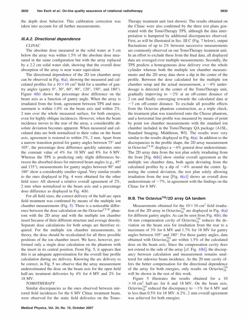
Therapy treatment unit �not shown�. The results obtained onthe Clinac were also confirmed by the three test plans gen-erated with the TomoTherapy TPS, although the data inter-pretation is hampered by additional discrepancies observed.First, as will be illustrated in Sec. III C �Fig. 7 below�, outputfluctuations of up to 2% between successive measurementsare commonly observed on our TomoTherapy treatment unit.In an effort to exclude these from the final data, all displayeddata are averaged over multiple measurements. Secondly, theTPS predicts a homogeneous dose delivery over the wholecylinder whereas both the multiple ion chamber measure-ments and the 2D array data show a dip in the center of theprofile. Between the dose calculated for the multiple ionchamber setup and the actual measurement, a �4% under-dosage is detected in the center of the TomoTherapy unit,gradually improving to �2% at an off-center distance of2 cm and finally converging towards the calculated data at�7 cm off-center distance. To exclude all possible effectsfrom the Octavius phantom construction, as a triple check,the treatment plan was transferred onto the Cheese phantom,and a horizontal line profile was measured by means of pointby point ion chamber measurements with the standard ionchamber included in the TomoTherapy QA package �A1SL,Standard Imaging, Middleton, WI�. The results were verysimilar to the results displayed in Fig. 6�a�. In addition to thediscrepancies in the profile shape, the 2D array measurementin OctaviusCT-IC displays a �4% general dose underestimate.The 2D array data from the test plan solely irradiating fromthe front �Fig. 6�b�� show similar overall agreement as themultiple ion chamber data, both again deviating from thecalculated profiles by a dip of �4% around the center. Ig-noring the central deviation, the test plan solely allowingirradiation from the rear �Fig. 6�c�� shows an overall doseunderestimate of �7%, in agreement with the findings on theClinac for 6 MV.
III.B. The Octavius729/2D array QA tandem
Measurements obtained for the 10�10 cm2 field irradia-tion of the 2D array in Octavius20
729 are displayed in Fig. 4�a�for different gantry angles. As can be seen from Fig. 4�b�, the16 mm compensation cavity of Octavius16
729 reduces the de-viation on the beam axis for irradiation from the rear to amaximum of 3% for 6 MV and 1.7% for 18 MV for gantryangles between 105° and 180°. For these gantry angles, dataobtained with Octavius20
729 are within 1.5% of the calculateddose on the beam axis. Since the compensation cavity doesnot extend to the side of the array �cf. Fig. 1�b��, the discrep-ancy between calculation and measurement remains unal-tered for sidewise beam incidence. As the 20 mm cavity of-fers the better compensation for the directional dependenceof the array for both energies, only results on Octavius20
729
will be shown in the rest of this work.Figure 5 illustrates the results obtained for a 10
�10 cm2 half-arc for 6 and 18 MV. On the beam axis,Octavius20
729 reduced the discrepancy to �1% for 6 MV andto less than 0.5% for 18 MV. A 2%, 2 mm overall agreement
was achieved for both energies.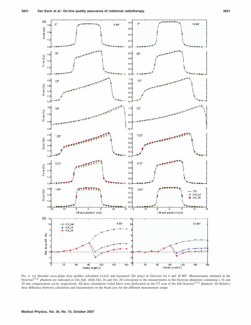
3831 Van Esch et al.: On-line quality assurance of rotational radiotherapy 3831
FIG. 4. �a� Absolute cross-plane dose profiles calculated �AAA� and measured �2D array� in Octavius for 6 and 18 MV. Measurements obtained in theOctaviusCT-IC phantom are indicated as Oct_full, while Oct_16 and Oct_20 correspond to the measurements in the Octavius phantoms containing a 16 and20 mm compensation cavity, respectively. All dose calculations �solid lines� were performed on the CT scan of the full OctaviusCT-IC phantom. �b� Relative
dose difference between calculation and measurement on the beam axis for the different measurement setups.Medical Physics, Vol. 34, No. 10, October 2007

3832 Van Esch et al.: On-line quality assurance of rotational radiotherapy 3832
Data obtained for the validation of the Octavius729/2DArray QA combination on the TomoTherapy treatment unit,are superposed on the graphs in Fig. 6. Figures 6�a� and 6�c�illustrate the considerable improvement in the measurementdata with the use of Octavius20
729. Octavius16729 provides simi-
lar, albeit slightly inferior results �not shown�. The line pro-files obtained for the cylindrical test plan shown in Fig. 6�a�now show the same discrepancies as the multiple ion cham-ber data when compared with the dose calculated by theTPS.
III.C. Pretreatment QA
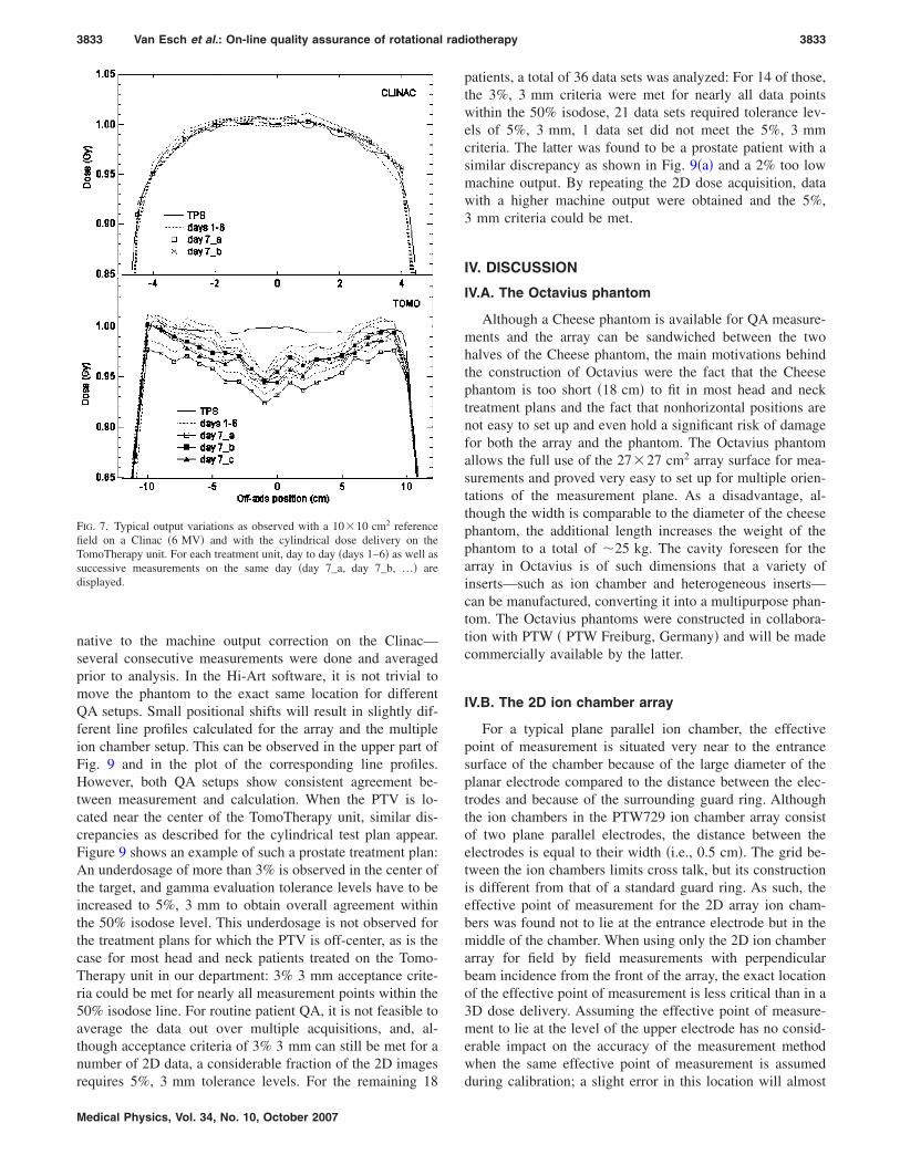
CLINACFirst, Fig. 7 shows typical results obtained during the
daily machine monitoring procedure at the start of the patientQA session. The day-to-day output variations on the Clinacare smaller than 1% and differences between consecutivemeasurements during the same QA session are smaller than0.2%. The stability of the beam allows us to correct for themachine output by means of a simple cross calibration.
For the dynamic arc deliveries on the Clinac, all measure-
FIG. 5. Measured and calculated half-arc delivery for a 10�10 cm2 fieldsize for a 6 and 18 MV treatment beam �500 MU�. Array measurementsobtained in the full OctaviusCT-IC phantom are indicated as Oct_2D_full.Oct_2D_20 corresponds to the measurements in the Octavius phantoms con-taining a 20 mm compensation cavity. Data obtained with the individual ionchambers are indicated as Oct_IC. All dose calculations �solid and dashedlines� were performed on the CT scan of the full OctaviusCT-IC phantom,containing the 2D array �Oct_2D TPS� or multiple ion chamber insert�Oct_IC TPS�.
ments agreed with the calculations within 3%, 3 mm for
Medical Physics, Vol. 34, No. 10, October 2007
nearly all measurement points encompassed by the 50% iso-dose line. Figure 8 shows typical results for a rectum�18 MV� and head and neck treatment �6 MV�, respectively.The squares on the isodose overlays indicate points thatfailed the gamma criteria. The doses measured with the mul-tiple ion chamber inserts are generally about 2% higher thanthe doses measured with the array but correspond equallywell to their calculated counterparts.
TOMOTHERAPYAs can be seen from Fig. 7, the output stability of the
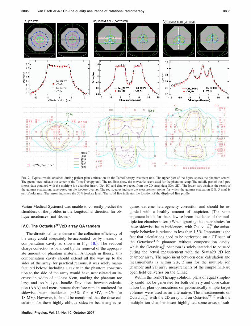
TomoTherapy was found to be of the order of 1%–2% forday-to-day as well as for intrasession consecutive measure-ments. Because of the latter, no correction for daily outputvariation can be applied to the subsequent patient QA plandelivery in clinical routine. Figure 9 shows typical resultsobtained with the pretreatment QA procedure in the coronal�Figs. 9�a� and 9�b�� and sagital �Fig. 9� plane on the Tomo-
FIG. 6. Measured and calculated treatment verification plans on the Tomo-Therapy treatment unit. A homogeneous dose delivery of 1 Gy to a centralcylinder was the planning objective in �a�; �b� and �c� illustrate results ob-tained for a treatment plan prohibiting irradiation from the rear and front ofthe array structure, respectively. Measurements obtained with the 2D arrayin the full OctaviusCT-IC phantom are indicated as Oct_2D_full; Oct_2D_20corresponds to the measurements in the Octavius phantoms containing a20 mm compensation cavity. Data obtained with the individual ion cham-bers are indicated as Oct_IC. All dose calculations �solid and dashed lines�were performed on the CT scan of the full OctaviusCT-IC phantom, contain-ing the 2D array �Oct_2D TPS� or the multiple ion chamber insert �Oct_ICTPS�.
Therapy unit. For the data displayed in Fig. 9—as an alter-
3833 Van Esch et al.: On-line quality assurance of rotational radiotherapy 3833
native to the machine output correction on the Clinac—several consecutive measurements were done and averagedprior to analysis. In the Hi-Art software, it is not trivial tomove the phantom to the exact same location for differentQA setups. Small positional shifts will result in slightly dif-ferent line profiles calculated for the array and the multipleion chamber setup. This can be observed in the upper part ofFig. 9 and in the plot of the corresponding line profiles.However, both QA setups show consistent agreement be-tween measurement and calculation. When the PTV is lo-cated near the center of the TomoTherapy unit, similar dis-crepancies as described for the cylindrical test plan appear.Figure 9 shows an example of such a prostate treatment plan:An underdosage of more than 3% is observed in the center ofthe target, and gamma evaluation tolerance levels have to beincreased to 5%, 3 mm to obtain overall agreement withinthe 50% isodose level. This underdosage is not observed forthe treatment plans for which the PTV is off-center, as is thecase for most head and neck patients treated on the Tomo-Therapy unit in our department: 3% 3 mm acceptance crite-ria could be met for nearly all measurement points within the50% isodose line. For routine patient QA, it is not feasible toaverage the data out over multiple acquisitions, and, al-though acceptance criteria of 3% 3 mm can still be met for anumber of 2D data, a considerable fraction of the 2D images
FIG. 7. Typical output variations as observed with a 10�10 cm2 referencefield on a Clinac �6 MV� and with the cylindrical dose delivery on theTomoTherapy unit. For each treatment unit, day to day �days 1–6� as well assuccessive measurements on the same day �day 7_a, day 7_b, …� aredisplayed.
requires 5%, 3 mm tolerance levels. For the remaining 18
Medical Physics, Vol. 34, No. 10, October 2007
patients, a total of 36 data sets was analyzed: For 14 of those,the 3%, 3 mm criteria were met for nearly all data pointswithin the 50% isodose, 21 data sets required tolerance lev-els of 5%, 3 mm, 1 data set did not meet the 5%, 3 mmcriteria. The latter was found to be a prostate patient with asimilar discrepancy as shown in Fig. 9�a� and a 2% too lowmachine output. By repeating the 2D dose acquisition, datawith a higher machine output were obtained and the 5%,3 mm criteria could be met.
IV. DISCUSSION
IV.A. The Octavius phantom
Although a Cheese phantom is available for QA measure-ments and the array can be sandwiched between the twohalves of the Cheese phantom, the main motivations behindthe construction of Octavius were the fact that the Cheesephantom is too short �18 cm� to fit in most head and necktreatment plans and the fact that nonhorizontal positions arenot easy to set up and even hold a significant risk of damagefor both the array and the phantom. The Octavius phantomallows the full use of the 27�27 cm2 array surface for mea-surements and proved very easy to set up for multiple orien-tations of the measurement plane. As a disadvantage, al-though the width is comparable to the diameter of the cheesephantom, the additional length increases the weight of thephantom to a total of �25 kg. The cavity foreseen for thearray in Octavius is of such dimensions that a variety ofinserts—such as ion chamber and heterogeneous inserts—can be manufactured, converting it into a multipurpose phan-tom. The Octavius phantoms were constructed in collabora-tion with PTW � PTW Freiburg, Germany� and will be madecommercially available by the latter.
IV.B. The 2D ion chamber array
For a typical plane parallel ion chamber, the effectivepoint of measurement is situated very near to the entrancesurface of the chamber because of the large diameter of theplanar electrode compared to the distance between the elec-trodes and because of the surrounding guard ring. Althoughthe ion chambers in the PTW729 ion chamber array consistof two plane parallel electrodes, the distance between theelectrodes is equal to their width �i.e., 0.5 cm�. The grid be-tween the ion chambers limits cross talk, but its constructionis different from that of a standard guard ring. As such, theeffective point of measurement for the 2D array ion cham-bers was found not to lie at the entrance electrode but in themiddle of the chamber. When using only the 2D ion chamberarray for field by field measurements with perpendicularbeam incidence from the front of the array, the exact locationof the effective point of measurement is less critical than in a3D dose delivery. Assuming the effective point of measure-ment to lie at the level of the upper electrode has no consid-erable impact on the accuracy of the measurement methodwhen the same effective point of measurement is assumed
during calibration; a slight error in this location will almost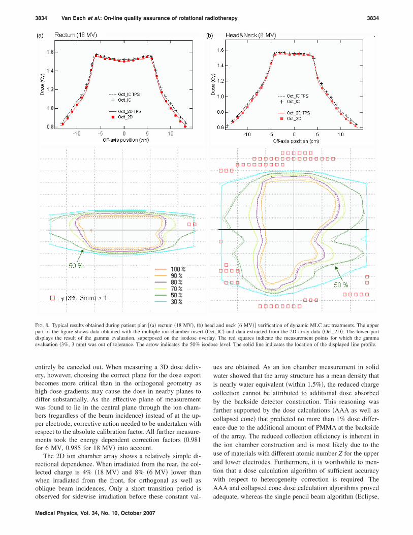
isodo
3834 Van Esch et al.: On-line quality assurance of rotational radiotherapy 3834
entirely be canceled out. When measuring a 3D dose deliv-ery, however, choosing the correct plane for the dose exportbecomes more critical than in the orthogonal geometry ashigh dose gradients may cause the dose in nearby planes todiffer substantially. As the effective plane of measurementwas found to lie in the central plane through the ion cham-bers �regardless of the beam incidence� instead of at the up-per electrode, corrective action needed to be undertaken withrespect to the absolute calibration factor. All further measure-ments took the energy dependent correction factors �0.981for 6 MV, 0.985 for 18 MV� into account.
The 2D ion chamber array shows a relatively simple di-rectional dependence. When irradiated from the rear, the col-lected charge is 4% �18 MV� and 8% �6 MV� lower thanwhen irradiated from the front, for orthogonal as well asoblique beam incidences. Only a short transition period is
FIG. 8. Typical results obtained during patient plan ��a� rectum �18 MV�, �b�part of the figure shows data obtained with the multiple ion chamber inserdisplays the result of the gamma evaluation, superposed on the isodose oevaluation �3%, 3 mm� was out of tolerance. The arrow indicates the 50%
observed for sidewise irradiation before these constant val-
Medical Physics, Vol. 34, No. 10, October 2007
ues are obtained. As an ion chamber measurement in solidwater showed that the array structure has a mean density thatis nearly water equivalent �within 1.5%�, the reduced chargecollection cannot be attributed to additional dose absorbedby the backside detector construction. This reasoning wasfurther supported by the dose calculations �AAA as well ascollapsed cone� that predicted no more than 1% dose differ-ence due to the additional amount of PMMA at the backsideof the array. The reduced collection efficiency is inherent inthe ion chamber construction and is most likely due to theuse of materials with different atomic number Z for the upperand lower electrodes. Furthermore, it is worthwhile to men-tion that a dose calculation algorithm of sufficient accuracywith respect to heterogeneity correction is required. TheAAA and collapsed cone dose calculation algorithms proved
and neck �6 MV�� verification of dynamic MLC arc treatments. The uppert_IC� and data extracted from the 2D array data �Oct_2D�. The lower part. The red squares indicate the measurement points for which the gammase level. The solid line indicates the location of the displayed line profile.
headt �Ocverlay
adequate, whereas the single pencil beam algorithm �Eclipse,
3835 Van Esch et al.: On-line quality assurance of rotational radiotherapy 3835
Varian Medical Systems� was unable to correctly predict theshoulders of the profiles in the longitudinal direction for ob-lique incidences �not shown�.
IV.C. The Octavius729/2D array QA tandem
The directional dependence of the collection efficiency ofthe array could adequately be accounted for by means of acompensation cavity as shown in Fig. 1�b�. The reducedcharge collection is balanced by the removal of the appropri-ate amount of phantom material. Although in theory, thiscompensation cavity should extend all the way up to thesides of the array, for practical reasons, it was solely manu-factured below: Including a cavity in the phantom construc-tion to the side of the array would have necessitated an in-crease in width of at least 6 cm, making the phantom toolarge and too bulky to handle. Deviations between calcula-tion �AAA� and measurement therefore remain unaltered forsidewise beam incidence ��3% for 6 MV, �2% for18 MV�. However, it should be mentioned that the dose cal-
FIG. 9. Typical results obtained during patient plan verification on the TomoThe green lines indicate the center of the TomoTherapy unit. The red lines shshows data obtained with the multiple ion chamber insert �Oct_IC� and datathe gamma evaluation, superposed on the isodose overlay. The red squaresout of tolerance. The arrow indicates the 50% isodose level. The solid line
culation for these highly oblique sidewise beam angles re-
Medical Physics, Vol. 34, No. 10, October 2007
quires extreme heterogeneity correction and should be re-garded with a healthy amount of suspicion. �The sameargument holds for the sidewise beam incidence of the mul-tiple ion chamber insert.� When ignoring the uncertainties forthese sidewise beam incidences, with Octavius20
729 the aniso-tropic behavior is reduced to less than 1.5%. Important is thefact that calculations need to be performed on a CT scan ofthe OctaviusCT-IC phantom without compensation cavity,while the Octavius20
729 phantom is solely intended to be usedduring the actual measurement with the Seven29 2D ionchamber array. The agreement between dose calculation andmeasurements is within 2%, 3 mm for the multiple ionchamber and 2D array measurements of the simple half-arcopen field deliveries on the Clinac.
Within the TomoTherapy solution, plans of equal simplic-ity could not be generated for both delivery and dose calcu-lation but plan optimizations on geometrically simple targetvolumes were used as an alternative. The measurements onOctavius20
729 with the 2D array and on OctaviusCT-IC with the
apy treatment unit. The upper part of the figure shows the phantom setups.e moveable lasers used for the phantom setup. The middle part of the figurected from the 2D array data �Oct_2D�. The lower part displays the result ofte the measurement points for which the gamma evaluation �3%, 3 mm� is
ates the location of the displayed line profile.
Therow thextra
indicaindic
multiple ion chamber insert highlighted some areas of sub-
3836 Van Esch et al.: On-line quality assurance of rotational radiotherapy 3836
optimal agreement between calculation and delivery for theTomoTherapy solution. Measurements reveal a �4% too lowdose delivery in the center of the TomoTherapy treatmentunit, gradually improving as the off-center distance in-creases. At 5 cm off-center distance, agreement is within 2%.The reason for these discrepancies is suspected to be subop-timal agreement between the preconfigured and actual beamprofile of the treatment unit. As published by Langen et al.,the beam profile shape changes with the wear-out of the tar-get: When normalizing beam profiles acquired over thecourse of seven weeks to their central value, they observed,e.g., a difference of �5% at a 20 mm off-axis position. Asthe beam configuration in the Hi-Art TPS remains fixed, ac-curate agreement with the changing beam profile cannot beachieved during the whole lifetime of the target. However,even though changes in the shape and magnitude of the mea-sured dose dip �Fig. 6� could indeed be observed over time,the discrepancy always remained visible, even immediatelyafter a target change. We suspect that the preconfigured pro-file deviates from reality at any given moment in time.Therefore, the above described test plans clearly illustrate theneed to not only verify the reproducibility of the beam pro-file, as is done during machine QA, but also to use simpleverification plans that can be compared to the TPS dose cal-culation. Making dose calculation available for static gantrydeliveries would provide a valuable asset for the physicist toverify the preconfigured beam data.
IV.D. Pre-treatment QA
When applying a correction factor for the daily machineoutput variation, excellent agreement �within 2%, 2 mm� be-tween measurement �2D Array and multiple ion chambers�and calculation was obtained for dynamic MLC arc treat-ments within the Varian solution. The dynamic MLC move-ments used in this study were relatively simple, but the ob-tained results suggest that the Octavius729/2D array tandemcould also be an efficient QA tool for more highly �intensity�modulated arc therapy �IMAT� treatments �not yet availableat our clinic�. Although the measurement method would beidentical, the obtained agreement may differ as complexMLC movements with small effective openings are not onlymore challenging to deliver, but the corresponding dose isalso more difficult to calculate. Although the Octavius729/2Darray setup could also be used for the composite plan verifi-cation of a static gantry IMRT treatment, obtained resultsmay be inferior to arc treatments when a substantial fractionof the dose is given through �nearly� lateral fields.
The use of the Octavius20729/2D array tandem on the To-
moTherapy treatment unit, considerably facilitates pretreat-ment QA. Prior to every verification session, 5 to 10 min arerequired for the phantom setup, depending on whether or notan MV-CT is obtained for the phantom positioning. The timeneeded per 2D dose measurement is then simply the timerequired to deliver the treatment. Comparison with the cal-culated planar dose is performed on-line and takes less than1 min. Unfortunately, for the planar dose export, a
workaround needs to be used as the Hi-Art TPS was notMedical Physics, Vol. 34, No. 10, October 2007
designed to support 2D dose exports. Although thisworkaround is cumbersome, it does not increase the time forpretreatment QA by more than 1 min. For most patients ac-ceptance criteria of 5%, 3 mm are met over the entire treat-ment field. Although 3%, 3 mm are more commonly usedacceptance criteria for IMRT treatment verification, the de-creased agreement between the 2D dose measurement andthe 2D dose calculation export can have many causes. First,the suboptimal agreement seen in the cylindrical test plan inthe center of the treatment beam is also expected to bepresent in the clinical treatment plans but less obvious tolocate because of the high gradients and because of the factthat the center of the beam is not always in the center of thephantom during QA plan delivery. Second, as noticed duringpretreatment daily machine QA, the absolute reproducibilityof the TomoTherapy during the course of the measurementswas of the order of 1%–2%, in agreement with the outputstability of 1.75% reported by Chen et al.38 Although theeffect of output variations could be reduced in the displayeddata by averaging over a number of data acquisitions, this isa highly time consuming procedure, not feasible in clinicalroutine. As a consequence, the machine output fluctuationsare inherently present in pretreatment patient plan deliveries.Third, although one is evaluating a 3D dose delivery, thegamma evaluation is performed between two planar datasets.This is a sufficiently accurate procedure for field by fieldIMRT pretreatment QA, but when verifying a 3D dose deliv-ery, small inaccuracies in either the selection of the exportplane or in the measurement setup can deteriorate the gammaevaluation outcome. Ideally, a 3D dose export �not yet avail-able� and 3D gamma calculation should therefore be used.
As already demonstrated during the daily QA session aspart of the pretreatment patient QA, the Octavius729/2D Ar-ray combination could potentially be used for the moreelaborate TomoTherapy machine QA as well. A single phan-tom setup would speed up the QA procedure. The fact that allarray measurements provide 2D absolute dose informationincreases their value and allows compacting of the QA pro-cedures. Furthermore, the discrepancies observed in the cen-ter of the cylindrical dose delivery inspire caution when tun-ing the machine output to a single, central ion chambermeasurement.
V. CONCLUSION
Although rotational radiotherapy treatments are increas-ingly used, the developed technology is still new and re-quires careful monitoring and verification. For the verifica-tion of these treatment methods, the Seven29 2D ionchamber array provides an overall accuracy comparable tothat of single ion chamber measurements when it is used incombination with the Octavius20
729 phantom. This phantomcontains a compensation cavity to rectify the different col-lection efficiency when the array is irradiated from the rear.It should be used in combination with the OctaviusCT-IC
phantom for dose calculation. The latter is a multipurposephantom that can also be used for multiple ion chamber mea-
surements, heterogeneity correction verification, and CT cali-
3837 Van Esch et al.: On-line quality assurance of rotational radiotherapy 3837
bration. This QA method facilitates the pretreatment verifi-cation process by providing on-line absolute 2D doseinformation.
ACKNOWLEDGMENTS
The authors would like to thank PTW �Freiburg, Ger-many� for their support and for providing dosimetric equip-ment. Special thanks should be attributed to Dr. Bernd All-gaier and Dr. Edmund Schule for their enthusiasm andfruitful scientific contributions. A research grant from Tomo-Therapy, Inc. �Madison, WI� was given to Clinique Ste Elisa-beth, Namur. 7Sigma has a research collaboration withVarian Medical Systems. The authors also wish to thank Ni-gel Wellock from Barts and London for providing them withthe tissue equivalent heterogeneous inserts and FabriceFeuillen for his assistance with the numerous CT scans.
a�Author to whom correspondence should be addressed. Electronic mail:[email protected]
1C. X. Yu, “Intensity-modulated arc therapy with dynamic multileaf colli-mation: An alternative to TomoTherapy,” Phys. Med. Biol. 40, 1435–1449 �1995�.
2L. Ma, C. X. Yu, M. Earl, T. Holmes, M. Sarfaraz, X. A. Li, D. Shepard,P. Amin, S. DiBiase, M. Suntharalingam, and C. Mansfield, “Optimizedintensity-modulated arc therapy for prostate cancer treatment,” Int. J.Cancer 96, 379–384 �2001�.
3C. X. Yu, X. A. Li, L. Ma, D. Chen, S. Naqvi, D. Shepard, M. Sarfaraz,T. W. Holmes, M. Suntharalingam, and C. M. Mansfield, “Clinical imple-mentation of intensity-modulated arc therapy,” Int. J. Radiat. Oncol.,Biol., Phys. 53, 453–463 �2002�.
4E. Wong, J. Z. Chen, and J. Greenland, “Intensity-modulated arc therapysimplified,” Int. J. Radiat. Oncol., Biol., Phys. 53, 222–235 �2002�.
5M. A. Earl, D. M. Shepard, S. Naqvi, X. A. Li, and C. X. Yu, “Inverseplanning for intensity-modulated arc therapy using direct aperture optimi-zation,” Phys. Med. Biol. 48, 1075–1089 �2003�.
6G. Bauman, E. Gete, J. Z. Chen, and E. Wong, “Simplified intensity-modulated arc therapy for dose escalated prostate cancer radiotherapy,”Med. Dosim. 29, 18–25 �2004�.
7W. Duthoy, W. De Gersem, K. Vergote, T. Boterberg, C. Derie, P. Smeets,C. De Wagter, and W. De Neve, “Clinical implementation of intensity-modulated arc therapy �IMAT� for rectal cancer,” Int. J. Radiat. Oncol.,Biol., Phys. 60, 794–806 �2004�.
8D. M. Shepard, D. Cao, M. K. N. Afghan, and M. A. Earl, “An arc-sequencing algorithm for intensity modulated arc therapy,” Med. Phys.34, 464–470 �2007�.
9N. L. Childress, L. Dong, and I. I. Rosen, “Rapid radiographic film cali-bration for IMRT verification using automated MLC fields,” Med. Phys.29, 2384–2390 �2002�.
10M. Bucciolini, F. B. Buonamici, and M. Casati, “Verification of IMRTfields by film dosimetry,” Med. Phys. 31, 161–168 �2004�.
11H. Mota, C. Sibata, S. Sasidharan, K. White, M. Wolfe, T. Jenkins, R.Patel, and R. Allison, “Improved calibration method of EDR films forIMRT-QA,” Med. Phys. 32, 1983 �2005�.
12C. Fiandra, U. Ricardi, R. Ragona, S. Anglesio, F. R. Giglioli, E. Calamia,and F. Lucio, “Clinical use of EBT model GafchromicTM film in radio-therapy,” Med. Phys. 33, 4314–4319 �2006�.
13L. Dong, J. Antolak, M. Salephour, K. Forster, L. O’Neill, R. Kendall,and I. Rosen, “Patient-specific point dose measurement for IMRT monitorunit verification,” Int. J. Radiat. Oncol., Biol., Phys. 56, 867–877 �2003�.
14H. Gustavsson, A. Karlsson, S. A. Back, L. E. Olsson, P. Haraldsson, P.Engstrom, and H. Nystrom, “MAGIC-type polymer gel for three-dimensional dosimetry: Intensity-modulated radiation therapy verifica-tion,” Med. Phys. 30, 1264–1271 �2003�.
15K. Vergote, Y. De Deene, W. Duthoy, W. De Gersem, W. DeNeve, E.Achten, and C. De Wagter, “Validation and application of polymer geldosimetry for the dose verification of an intensity-modulated arc therapy�IMAT� treatment,” Phys. Med. Biol. 49, 287–305 �2004�.
16
T. R. Mackie, T. Holmes, S. Swerdloff, P. Reckwerdt, J. O. Deasy, J.Medical Physics, Vol. 34, No. 10, October 2007
Yang, B. Paliwal, and T. Kinsella, “TomoTherapy: A new concept for thedelivery of dynamic conformal radiotherapy,” Med. Phys. 20, 1709–1719�1993�.
17T. R. Mackie, J. Balog, K. Ruchala, D. Shepard, S. Aldridge, E. Fitchard,P. Reckwerdt, G. Olivera, T. McNutt, and M. Mehta, “TomoTherapy,”Semin. Radiat. Oncol. 9, 108–117 �1999�.
18M. Al-Ghazi, R. Kwon, J. Kuo, N. Ramsinghani, and R. Yakoob, “TheUniversity of California, Irvine experience with TomoTherapy using thePeacock system,” Med. Dosim. 26, 17–27 �2001�.
19J. S. Welsh, R. R. Patel, M. A. Ritter, P. M. Harari, T. R. Mackie, and M.P. Mehta, “Helical TomoTherapy: An innovative technology and approachto radiation therapy,” Technol. Cancer Res. Treat. 1, 311–316 �2002�.
20A. W. Beavis, “Is TomoTherapy the future of IMRT?” Br. J. Radiol. 77,285–295 �2004�.
21D. A. Low, K. K. S. C. Chao, S. Mutic, R. L. Gerber, C. A. Perez, and J.A. Purdy, “Quality assurance of serial TomoTherapy for head and neckpatient treatments,” Int. J. Radiat. Oncol., Biol., Phys. 42, 681–692�1998�.
22J. Balog, T. Holmes, and R. Vaden, “A helical TomoTherapy dynamicquality assurance,” Med. Phys. 33, 3939–3950 �2006�.
23J. D. Fenwick, W. A. Tomé, H. A. Jaradat, S. K. Hui, J. A. James, J. P.Balog, C. N. DeSouza, D. B. Lucas, G. H. Olivera, T. R. Mackie, and B.R. Paliwal, “Quality assurance of a helical TomoTherapy machine,” Phys.Med. Biol. 49, 2933–2953 �2004�.
24K. M. Langen, S. L. Meeks, D. O. Poole, T. H. Wagner, T. R. Willoughby,O. A. Zeidan, P. A. Kupelian, K. J. Ruchala, and G. H. Olivera, “Evalu-ation of a diode array for QA measurements on a helical TomoTherapyunit,” Med. Phys. 32, 3424–3430 �2005�.
25P. B. Greer and C. C. Popescu, “Dosimetric properties of an amorphoussilicon electronic portal imaging device for verification of dynamic inten-sity modulated radiation therapy,” Med. Phys. 30, 1618–1627 �2003�.
26B. Warkentin, S. Steciw, S. Rathee, and B. G. Fallone, “Dosimetric IMRTverification with a flat-panel EPID,” Med. Phys. 30, 3143–3155 �2003�.
27A. Van Esch, T. Depuydt, and D. P. Huyskens, “The use of an a Si-basedEPID for routine absolute dosimetric pretreatment verification of dynamicIMRT fields,” Radiother. Oncol. 71, 223–234 �2004�.
28E. Spezi, A. L. Angelini, F. Romani, and A. Ferri, “Characterization of a2D ion chamber array for the verification of radiotherapy treatments,”Phys. Med. Biol. 50, 3361–3373 �2005�.
29B. Poppe, A. Blechschmidt, A. Djouguela, R. Kollhoff, A. Rubach, K. C.Willborn, and D. Harder, “Two-dimensional ionization chamber arraysfor IMRT plan verification,” Med. Phys. 33, 1005–1015 �2006�.
30A. Van Esch, L. Tillikainen, J. Pyykkonen, M. Tenhunen, H. Helminen, S.Siljamäki, J. Alakuijala, M. Paiusco, M. Iori, and D. P. Huyskens, “Test-ing of the analytical anisotropic algorithm for photon dose calculation,”Med. Phys. 33, 4130–4147 �2006�.
31J. M. Lydon, “Photon dose calculations in homogeneous media for atreatment planning system using a collapsed cone superposition convolu-tion algorithm,” Phys. Med. Biol. 43, 1813–1822 �1998�.
32M. R. Arnfield, C. H. Siantar, J. Siebers, P. Garmon, L. Cox, and R.Mohan, “The impact of electron transport on the accuracy of computeddose,” Med. Phys. 27, 1266–1274 �2000�.
33M. Miften, M. Wiesmeyer, S. Monhofer, and K. Krippner, “Implementa-tion of FFT convolution and multigrid superposition models in the FO-CUS RTP system,” Phys. Med. Biol. 45, 817–833 �2000�.
34M. M. Aspradakis, R. Morrison, N. Richmond, and A. Steele, “Experi-mental verification of convolution/superposition photon dose calculationsfor radiotherapy treatment planning,” Phys. Med. Biol. 48, 2873–2893�2003�.
35D. A. Low, W. B. Harms, M. Sasa, and J. A. Purdy, “A technique for thequantitative evaluation of dose distributions,” Med. Phys. 25, 656–661�1998�.
36T. Depuydt, A. Van Esch, and D. P. Huyskens, “A quantitative evaluationof IMRT distributions: Refinement and clinical assessment of the gammaevaluation,” Radiother. Oncol. 62, 309–319 �2002�.
37W. Lu, G. H. Olivera, M. L. Chen, P. J. Reckwerdt, and T. R. Mackie,“Accurate convolution/superposition for multi-resolution dose calculationusing cumulative tabulated kernels,” Phys. Med. Biol. 50, 655–680�2005�.
38C. Chen, J. Meadows, and T. Bichay, “TomoDose: A daily quality assur-
ance device for helical TomoTherapy,” Med. Phys. 33, 2207 �2006�.