Embed Size (px)
Citation preview

On-line uninterruptible power supply
User manual


-i-
Contents
CONTENTS ............................................................................................................ I
1 BRIEF INTRODUCTION ............................................................................. 1
1.1 PROLEGOMENON ...................................................................................... 1
1.2 FIVE DESIGN POINTS ................................................................................. 1
1.3 NOTE ........................................................................................................ 1
2 CONFIGURATION AND FUNCTION ....................................................... 3
2.1 FRONT PANEL ........................................................................................... 3
2.2 APPEARANCE ............................................................................................ 5
2.3 SWITCH POSITION AND FUNCTION ............................................................. 6
3 PLACEMENT NOTES .................................................................................. 8
3.1 TRANSIT OR MOVE .................................................................................... 8
3.2 PLACEMENT ............................................................................................. 8
4 INSTALLATION ......................................................................................... 11
4.1 INPUT ..................................................................................................... 11
4.2 OUTPUT .................................................................................................. 14
4.3 DC INPUT WIRING ................................................................................... 17
5 OPERATION PROCESS ............................................................................ 18
5.1 PREPARATION BEFORE START-UP. ............................................................ 18
5.2 OPERATION PROCESS FOR FIRST START-UP .............................................. 18
5.3 OPERATION PROCESS FOR ROUTINE TURN-OFF ........................................ 20
5.4 OPERATION PROCESS IF UPS IS NOT IN USE ....................................... 20
6 STATUS HANDLING .................................................................................. 21
6.1 SYMBOL SIGNIFICATION .......................................................................... 21
6.2 STATUS INDICATION AND HANDLING .......................................... 21

-ii-
7 UPS CONFIGURATION IN DIFFERENT MODES ................................ 30
7.1 UPS IN NORMAL MODE ........................................................................... 30
7.2 UPS MODE WHILE UTITILTY POWER FAIL ..................................... 30
7.3 UPS IN STATIC BYPASS MODE ............................................................... 31
7.4 BATTERY AND CHARGER ......................................................................... 31
7.5 DAILY MAINTENANCE ............................................................................. 32
8 COMMUNICATION INTERFACE ........................................................... 33
9 SPECIFICATION ........................................................................................ 36
10 SHIPPING LIST .......................................................................................... 38

-1-
1 BRIEF INTRODUCTION
1.1 Prolegomenon
The product is designed for mini to micro level computer companies
who is looking for exquisite quality, excellent function and easy to operate.
This product is the optimum power supply partner for the office and ensures
you can attain optimal clean power quality.
1.2 Five design points
1. Slim design
2. Light weight and convenient to transport
3. Reliable and easy to operate
4. Convenient to maintain
5. Packaged material with environmental protection
1.3 Note
The manual explains how to operate and maintain the system.
To optimize the use of the UPS, please note the following:
1. Read the manual carefully before use
2. Perform the operation strictly according to operating process
3. Place the UPS in a convenient, dry and safe area.
4. Install the power according to the instructions manual
5. Do not open the covers to avoid injury
6. Please charge batteries once every 6 months if not in use
7. Do not overload the UPS
8. Keep the manual for the future reference
9. Do not use the UPS while in fault condition. See manual for various
troubleshooting methods
10. Please keep UPS area clean and run in a temperature controlled

-2-
environment.
11. Do not leave objects on top of the UPS
12. Do not obstruct the air flow

-3-
2 CONFIGURATION AND FUNCTION
2.1 Front panel
1) Welcome screen
WELCOME
×××××××××
2) Display of system status
×××××
××KVA.
3) Display of input voltage value*
ON LINE
AC IN: 230V
4) Display of input frequency value*
ON LINE
AC FRE:50Hz
Figure 1 Symbol instruction of front panel indicator.
LCD
Output indic ator
Fault indicator
Battery energy indicator
Overload indica tor
Bypass indicator
Switch ON
Switch OFF
Cyc le display botton
Input indicator

-4-
5) Display of output voltage value*
ON LINE
OUTPUT: 230V
6) Display of output frequency value
ON LINE
OUT FRE:50Hz
7) Display of output power percentage
ON LINE
LOAD: 80%
8) Display of battery voltage value
ON LINE
BATTERY: 218V
9) Temperature display in machine
ON LINE
TEMP: 33℃
Note:ON BYPASS mode, the output voltage and frequency
are displayed “0”. LED would display only after the unit is
switched on.
*These parameters vary with machine model.
10) LCD cycle display switch button: digital signal display items
switch button.
11) UPS switch button: UPS general switch button.
(1) Turn on UPS inverter by pressing the “ON” key. UPS
convert to UPS inverter power output 20s later, UPS pure
sine wave AC output power is supplied by UPS internal
power supply equipment.
(2) By pressing the OFF switch button for 3s,the inverter
shuts down and the UPS turns to bypass mode.
The button acts as general switch.

-5-
2.2 Appearance
1
2
7
3
4
5
68
9
1. Control panel: UPS display and operation panel
2. Emission heat ventilation hole: The ventilation hole and other small
long ventilation holes should be kept open for good ventilation.
3. RS232 communication interface: Standard communication interface
between UPS and computer.
4. Power switch: Power switch controls input, output and battery
power switch at the same time.
5. Wiring terminal: Power wiring terminal for input, output and battery
connections.
6. Dry contact (optional): 4 routes 10A dry contact output
7. Wheels: Movable wheels
8. SNMP card (optional): remotely monitor the UPS
9. RS485 (Optional): communicate with UPS
Figure 2 Front panel
Figure 2 Front panel Figure 3 Rear panel

-6-
2.3 Switch position and function
1. Input switch: when turned on, the UPS is
connected with AC and battery power
Switch position: (1-3kva 48v)
1. BYPASS OUTPUT SWITCH
When switch is turned on, power is provided to the
UPS and the UPS runs in bypass.
2. RECTIFIER INPUT SWITCH
When switched on, the AC will be rectified.
3. BATTERY INPUT SWITCH
When turned on, the battery begins to charge and
discharges accordingly.
Switch position: (1-3kva 192v)
4. OUTPUT SWITCH (optional): when turned on,there is output power
5. MAINTENANCE BYPASS SWITCH (optional): When turning on the
switch, the AC will bypass the UPS and supply power to the load without the
UPS. The UPS can be serviced or repaired
INPUT
RE
CT
IFIE
R
BY
PA
SS
BA
TT
ER
Y

-7-
Switch Position (15-20kva)
1. BYPASS OUTPUT SWITCH When switch is turned on, power is
provided to the UPS and the UPS runs in bypass.
2. AC INPUT SWITCH When switched on, the AC will be rectified.
3. BATTERY INPUT SWITCH When turned on, the battery begins to charge
and discharges accordingly.
4. OUTPUT SWITCH (optional): when turned on, there is output power.
5. MAINTENANCE BYPASS SWITCH (optional): When turning on the
switch, the AC will bypass the UPS and supply power to the load without the
UPS. The UPS can be serviced or repaired

-8-
3 PLACEMENT NOTES
3.1 Transit or move
1. Please disconnect all connections. (First turn off before performing)
2. Please do not move UPS while functioning.
3.2 Placement
1. Do not place the UPS on a slope or uneven surface. (Figure 4)
Figure 4
2. Place the UPS in a room where there is good ventilation. The rear
panel of UPS and two side faces should be more than 10cm away
from the wall. (Figure 5)
3. Do not install the UPS in direct sunlight, rain or damp areas. (Figure
6, 7)

-9-
Figure 5
Figure6 Figure 7
4. Please keep away from any fire source and high temperatures to
avoid overheating. (Figure 8)
5. Do not place goods on the UPS. (Figure 9)
6. Do not install the UPS in places which contains caustic gasses.
(Figure 10)
7. Running environment temperature: 0℃-40℃.

-10-
Figure 8
Figure 10
Figure 9

-11-
4 INSTALLATION
4.1 Input
1. Forbid using general household sockets, the maximum current of
general sockets is 15A, the socket may cause fire because of overload.
2. Turn off power when connecting cables, prohibit operation on live
wires.
3. Please connect UPS input terminal to utility power from a switchboard.
Figure 11.
Note: Do not swop live and neutral
4. Back panel position and connection
(1) Remove two screws with “+” screwdriver (Figure 12)
(2) Open the back panel and inspect the wiring terminal below the
power switch. (Figure 13)
5. Feed in the input, output and battery pack power cables through the
inlet/outlet hole and connect to the terminal block on the UPS.

-12-
Figure 12
Figure 13
6. Connect power correctly
(1) Live (L): There is 220V relative to other two holes.
(2) Neutral (N): there is 220V relative to the Live, there is 0.5-2V
relative to the ground. (Load current circulate through neutral)

-13-
(3) Ground (G): Connect correctly to ground in the switchboard.
7. If the difference between the neutral and the ground is more than 2V
or it cannot meet the requirements, please reinstall good grounding to
ensure safety of UPS operation.
8. The comparison list of input current rating and input cable size is as
follows:
Model Max. input Input wire Terminal specification
1KVA 8.5A 12AWG 5.5-5
2KVA 14A 10AWG 5.5-5
3KVA 17.5A 10AWG 5.5-5
4KVA 22.5A 10AWG 5.5-5
6KVA 31A 10AWG 5.5-5
8KVA 40A 8AWG 8.5-6
10KVA 50A 8AWG 8.5-6
12KVA 60A 6AWG 16-6
15KVA 72A 6AWG 16-6
20KVA 90A 4AWG 25-6
Table 1
9. The power cable and terminal must be a first-grade product
manufactured by an authentic manufacturer.
10. Do not wrap the power cables around the terminal block screws.
11. After fastening the input cable, to avoid short-circuit, please see if the
input cable contacts properly and does not touch other wiring.
12. Follow the electrical laws when doing installation.
13. Avoid using the same circuit breaker with other equipment when
connecting to the switchboard.

-14-
14. For 3Ø 4-wire connections,
please respectively measure
the voltage between R/N,S/N,
T/N with a meter and see if
they are close to 220V, then
connect L cable of the UPS to
the cable whose voltage
measured the highest
(meaning supply power of this
phase is lighter than that of the
other two phase), the N cable
of UPS is connected to utility
neutral cable N, the UPS-GND
is connected to the grounding
club.
15. If the model of the unit you purchased is 110V input, please connect
UPS-L cable into line, connect N cable into neutral cable, and connect
UPS-GND cable to grounding club.
Please note that this equipment is single phase 220V or 110V, do
not connect to 3 phase 380V.
4.2 Output
1. Please refer to output installation table 2 when installing.
2. Position and way of connection, refer to figure 15.

-15-
3. Output power cable should be sized according to UPS size, do not use
undersized cabling. Please refer to Table 2
Model Max. output current Output cable Terminal specification
1KVA 4A 12AWG 5.5-5
2KVA 7.5A 10AWG 5.5-5
3KVA 11A 10AWG 5.5-5
4KVA 15A 10AWG 5.5-5
6KVA 22A 10AWG 5.5-5
8KVA 30A 8AWG 8.5-6
10KVA 36A 8AWG 8.5-6
12KVA 44A 8AWG 16-6
15KVA 55A 6AWG 16-6
20KVA 72A 6AWG 16-6
Table 2
4. Avoid short-circuit and overload.
5. The comparison between output current rating and output cable size is
listed in Table 2.
6. The ground to this unit only acts as reference point, if the grounding is
bad, that may cause disturbance and false management, and affect UPS
performance. Speak to professional personnel for assistance

-16-
immediately.
7. Use a good grounding system.
8. Try to make the ground close to the connecting point of the grounding
club or origination point in the switchboard. Please refer to figure 16.
* Please install wiring according to input voltage
Contact an electrician or our service department if there is problem with
the installation.

-17-
4.3 DC input wiring
1. DC input connection please refer to AC input installation rules.
2. Connection way and position, please refer to figure 17.
Model Max. Battery
current Battery cable
Terminal
specification
1KVA(48Vdc) 25A 12AWG 5.5-5
2KVA(48Vdc) 50A 10AWG 5.5-5
3KVA(48Vdc) 75A 10AWG 5.5-5
1KVA 6A 12AWG 5.5-5
2KVA 12A 10AWG 5.5-5
3KVA 18A 10AWG 5.5-5
4KVA 25A 10AWG 5.5-5
6KVA 37A 10AWG 5.5-5
8KVA 50A 8AWG 10-6
10KVA 60A 6AWG 16-6
12KVA 75A 6AWG 16-6
15KVA 90A 4AWG 25-6
20KVA 120A 4AWG 25-6
Table 3
BATT- BATT+
Figure 17

-18-
5 OPERATION PROCESS
5.1 Preparation before start-up.
To ensure the UPS runs normal and correct, please confirm the
following. (Refer to figure 2)
1. Verify the power switch on the back panel is in the “OFF” position.
2. Verify the installation procedure again. (Figure 4 to 10)
3. Pull the power cables by hand and see if there are any looseness, if so,
retighten them.
4. Do not connect load.
5. Inspect if the input voltage meets the demand of the UPS (220V±10%)
with a meter.
5.2 Operation process for first start-up
After verifying the above items are correct, please turn on the UPS
according to the following ways: (Refer to figure 1, figure 2 and figure
3)
1. Please switch the breaker “NON-
FUSEBREAKER”
(NFB) on the back panel to the “ON”
position. Input indicator light and
bypass indicator light on the front
panel are lit at the same time.
Figure 18
LCD
O utput indicator
Fault indicator
Batte ry energy indicator
O verload indic ator
Bypass indica tor
Switch ON
Switch OFF
Cycle display botton
Input indicator

-19-
2. Press the “ON” button on front
panel. As per figure 19. The
input indicator and the bypass
indicator are solid on. LCD
display is lit on. Output is utility
powered via bypass.
3. After 20s, input indicator light
on front panel is lit on, bypass
indicator is off and output
indicator is lit on. The welcome
information is displayed on LCD,
output is UPS inverter powered.
4. Shutdown input power of UPS,
utility indicator light is off, the
welcome information is displayed on
the LCD, and output is UPS inverter
powered, as following drawing. UPS
sounds every four seconds, which
indicates the UPS runs on battery at
present. The sound will automatically
stop 90s later. UPS will sound alarm
every 1s again when battery power is
to be exhausted.
Figure 19
Figure 20
Figure 21
LCD
O utput indicator
Fault indicator
Batte ry energy indicator
O verload indic ator
Bypass indica tor
Switch ON
Switch OFF
Cycle display botton
Input indicator
Starti ng Wai t...
LCD
O utput indicator
Fault indicator
Batte ry energy indicator
O verload indic ator
Bypass indica tor
Switch ON
Switch OFF
Cycle display botton
Input indicator
Welcome toXXXXXXXXXX
LCD
O utput indicator
Fault indicator
Batte ry energy indicator
O verload indic ator
Bypass indica tor
Switch ON
Switch OFF
Cycle display botton
Input indicator
Welcome toXXXXXXXXXX

-20-
5. Utility indicator will be lit on when UPS input power source is
resumed. Press the LCD display cycle switch button to switch items
displayed, inspect if the display value is normal, thus first startup
procedure has been completed. Please measure output voltage and see
if it meets the requirement, then connect the load to the UPS output
terminal. Use pure power provided by UPS.
6. After load is connected, press LCD display cycle switch button to
switch items displayed until it displays the output power percent %. If
the value displayed is more than 100%, please disconnect unimportant
load till the value displayed is less than 100%.
5.3 Operation process for routine turn-on/off
If you want to switch the UPS on or off, please operate the UPS
according to the following ways:
1. You can switch off the UPS by pressing the “OFF’ button on front
panel. At this time the UPS is on bypass mode, output is utility
powered and the batteries are charged.
2. Always turn on the UPS by pressing the “ON” button when in daily
operation.
5.4 Operation process if UPS is not in use
1. If UPS is not used for more than ten days, please first turn off the UPS
by pressing the “OFF” button on front panel, then switch the power
switch NFB on the back panel to the “OFF” position.
2. If UPS is not used for more than three months, please run the UPS for
more than 24 hours before the first start-up process and keep the
battery voltage level full to extend battery life.

-21-
6 STATUS HANDLING
6.1 Symbol signification
Note: If indicator light flashes, the flash period is synchronized with the
buzzer and indicates alarms for different modes.
6.2 Status indication and handling
Please refer to the indicators on the UPS panel, the LCD indicator and the
LED lights will be as follows to indicate what mode the UPS is in.
1. Panel indicator status:
(1) UPS running status:
Utility is normal, UPS runs
normal and UPS is used
under full-load.
(2) Action to be taken:
non-needed.
Figure 22
LCD
O utput indicator
Fault indicator
Batte ry energy indicator
O verload indic ator
Bypass indica tor
Switch ON
Switch OFF
Cycle display botton
Input indicator
C urrent Load100% 7/8

-22-
2. Panel indicator status:
(1) UPS running status:
Utility is normal, UPS runs
normal and battery capacity
is above 90%.
(2) Action to be taken:
non-needed.
1. Panel indicator status:
(1) UPS running status:
Utility supplies power of
220Vac and UPS runs
normal.
(2) Action to be taken:
non-needed.
4. Panel indicator status:
(1) UPS running status:
Utility is normal, UPS runs
normal and battery voltage
is low.
(2) Action to be taken:
The charger is faulty, please
replace charging board.
*Note: the material parameters indicated may vary with the UPS
Figure 25
Figure 24
Figure 23
LCD
O utput indicator
Fault indicator
Batte ry energy indicator
O verload indic ator
Bypass indica tor
Switch ON
Switch OFF
Cycle display botton
Input indicator
Battery Voltage220V 6/8
LCD
O utput indicator
Fault indicator
Batte ry energy indicator
O verload indic ator
Bypass indica tor
Switch ON
Switch OFF
Cycle display botton
Input indicator
Input Volt age220V 2/8
LCD
O utput indicator
Fault indicator
Batte ry energy indicator
O verload indic ator
Bypass indica tor
Switch ON
Switch OFF
Cycle display botton
Input indicator
Battery Voltage185V 6/8

-23-
6. Panel indicator status:
(1) UPS running status:
Utility power is normal and it
converts to utility mode. UPS
will not start-up unless the
“ON” button is pushed down
on the UPS panel.
(2) Action to be taken:
Refer to status dealing flow
Chart 2.
7. Panel indicator status:
(1) UPS running status:
Utility supplies power.
Under overload 125%,
overload indicator is lit on
and the buzzer long beeps.
(2) Action to be taken:
Please remove load to ensure
the percentage of LCD
output power indicated is
below 100%. If the problem
is still present after removing load,
please refer to flow Chart 3
of status handling.
Figure 26
Figure 27
LCD
O utput indicator
Fault indicator
Batte ry energy indicator
O verload indic ator
Bypass indica tor
Switch ON
Switch OFF
Cycle display botton
Input indicator
LCD
O utput indicator
Fault indicator
Batte ry energy indicator
O verload indic ator
Bypass indica tor
Switch ON
Switch OFF
Cycle display botton
Input indicator
C urrent Load125% 7/8
-24-
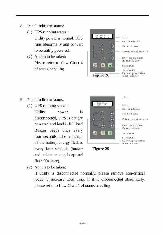
8. Panel indicator status:
(1) UPS running status:
Utility power is normal, UPS
runs abnormally and convert
to be utility powered.
(2) Action to be taken:
Please refer to flow Chart 4
of status handling.
9. Panel indicator status:
(1) UPS running status:
Utility power is
disconnected, UPS is battery
powered and load is full load.
Buzzer beeps once every
four seconds. The indicator
of the battery energy flashes
every four seconds (buzzer
and indicator stop beep and
flash 90s later).
(2) Action to be taken:
If utility is disconnected normally, please remove non-critical
loads to increase used time. If it is disconnected abnormally,
please refer to flow Chart 1 of status handling.
Figure 28
LCD
O utput indicator
Fault indicator
Batte ry energy indicator
O verload indic ator
Bypass indica tor
Switch ON
Switch OFF
Cycle display botton
Input indicator
Welcome toXXXXXXXXXX
Figure 29
LCD
O utput indicator
Fault indicator
Batte ry energy indicator
O verload indic ator
Bypass indica tor
Switch ON
Switch OFF
Cycle display botton
Input indicator
C urrent Load100% 7/8

-25-
10. Panel indicator status:
(1) UPS running status:
Utility power is disconnected
and UPS is battery powered.
Buzzer beeps once every one
second when the battery
power will be exhausted.
(2) Action to be taken:
UPS will shut down, please
save files and shutdown your
computers.
11. Panel indicator status:
(1) UPS running status:
Utility power may have been
disconnected and battery
power has been exhausted,
shutdown UPS
automatically.
(2) Action to be taken:
When utility power comes
back, UPS will
automatically restart. If
utility power is disconnected for a long time (above 6 hours),
please turn off UPS according to switch on/off program for power
disconnection of long time.
Figure 31
LCD
O utput indicator
Fault indicator
Batte ry energy indicator
O verload indic ator
Bypass indica tor
Switch ON
Switch OFF
Cycle display botton
Input indicator
Figure 30
LCD
O utput indicator
Fault indicator
Batte ry energy indicator
O verload indic ator
Bypass indica tor
Switch ON
Switch OFF
Cycle display botton
Input indicator
XXXX-proAC : Loss BAT: Low

-26-
Flow chart 1 of status handing

-27-
Flow chart 2 of status handing

-28-
Flow chart 3 of status handing Flow chart 3 of status handing

-29-
Flow chart 4 of status handing

-30-
7 UPS Configuration in different modes
InverterRectifier
StaticSwitch
Filter
Output
BatteryCharger
Filter
Input
7.1 UPS in normal mode
When UPS runs normally, after high-frequency harmonic noise in utility
power is filtered by the filter, utility power charges the battery pack via the
charger and keeps battery power at full voltage level, while utility power is
converted to DC power via the rectifier and is converted into pure sine wave
power via the inverter, feeding the load via the static switch and filter.
InverterRectifier
StaticSwitch
Filter
Output
BatteryCharger
Filter
Input
7.2 UPS mode while utility power fail
When the utility fails, battery power is supplied through the inverter and the
load is supplied through the static switch.
Figure 32
Figure 33

-31-
InverterRectifier
StaticSwitch
Filter
Output
BatteryCharger
Filter
Input
7.3 UPS in static bypass mode
The UPS will switch to bypass in the following conditions:
1. Overload
2. Inverter failure
3. During start-up
4. When the inverter is switched off
5. UPS over-temperature.
InverterRectifier
StaticSwitch
Filter
Output
BatteryCharger
Filter
Input
7.4 Battery and charger
1. When the breaker on back panel is on the position of “ON”, the
batteries can automatically be charged and the charger can charge to
Figure 34
Figure 35

-32-
90% of the battery capacity after 8 hours.
2. The following chart will give a rough estimate on discharge times
during utility failure.
Figure 36
3. Should you wish to extend battery autonomy time, please contact your
closest UPS service centre.
4. Keep the batteries fully charged to extend the battery life.
7.5 Daily maintenance
1. UPS should be cleaned and maintained termly, avoid any dust.
2. Please clean UPS lightly with a soft cloth.
3. Termly inspect all connections and avoid heat, looseness or humidity.
4. Please keep good ventilation at inlet/outlet holes, termly inspect the
holes and ensure they are obstruction free.
5. The battery is sealed lead-acid and maintenance-free. Batteries must
be inspected once every six months.

-33-
8 Communication interface
1. Monitoring software is supplied with the UPS for monitoring purposes.
2. A serial cable is supplied for communication between the UPS and
computer. The supplied serial cable connects to the RS232
communication interface on back panel of UPS. The user is able to
monitor the status of the UPS through the computer interface software
works on operating software such as WINDOWS, LINUX, NOVELL,
etc. When utility power is disconnected, the UPS notifies via the
software that there is a utility fault and send out alarm information. A
predetermined time can be set in order for the software to automatically
save files and shutdown the operating system. When utility power
returns, the UPS will automatically run and system can automatically
start.
3. Transmitted data from the UPS includes input voltage value, output
voltage value, output frequency, input frequency, battery capacity
percent, used load percent, UPS internal temperature, etc.

-34-
4. Serial cable
RS232 appearance, figure 38
The pinout of RS232 is:
PIN2: RS232 RXD
PIN3: RS232 TXD
PIN5: GND
Figure 38
5. Dry contact (optional)
Common
Fault
AC fail
Bypass
Low BAT
Common
Figure 37

-35-
1. Pin 1 and 10 are common contact
2. Fault: Pin 2 is NO type contact, pin 3 is NC type contact. When UPS
works normally, pin2 and pin 1 are open; when UPS fails, pin2 and pin1
are closed, whereas pin3 and pin 1 are open.
3. AC fail: pin 4 is NO type contact, pin 5 is NC type contact. When AC is
normal, pin 4 and pin 1 are closed; when AC abnormal, pin 4 and pin 1
are closed, whereas pin 5 and pin 1 are open.
4. Bypass: pin 6 is NO type contact, pin 7 is NC type contact. When UPS
works normally, pin 6 and pin 1 are open; when UPS works in bypass,
pin 6 and pin 1 are closed, whereas pin 7 and pin 1 are open
5. Low BAT: pin 8 is NO type contact, pin 9 is NC type contact. When
UPS works noramlly, pin 8 and pin 1 are closed; when UPS battery low,
pin 8 and pin 1 are closed, whereas pin 9 and pin 1 are open.

-36-
9 SPECIFICATION
Model 1KVA 2KVA 3KVA 4KVA 6KVA 8KVA 10KVA 12KVA 15KVA 20KVA
AC input
Voltage 160-260VAC or 160-310VAC
Frequency 50)Hz±5%
Phase Single
Max. 8.5A 14A 17.5A 22.5A 31A 40A 50A 60A 70A 90A
AC output
Voltage 230VAC
Frequency 50Hz
Voltage stability ±1%
Frequency
stability
±0.5% (battery mode)
Wave form SPWM sine wave
Power factor 0.8
Distortion <3%(linear load)
Transient
response
≤4%(100% load ~ 0% load)
Battery
Voltage 48VDC/192VDC 192VDC
Rated charging
current
Standard:1.2A long run: 6A, 12A (optional)
Model Maintenance-free lead-acid battery
Runtime Refer to figure 39
Charging 90% capacity after 8-10 hours
Alarm
Utility disconnect Buzzer beeps once every four seconds
Battery exhausted Buzzer beeps once every one second
Overload Load indicator light is solid on, buzzer continuously beeps for a long-time.
UPS abnormal Fault indicator light is solid on, buzzer continuously beeps for a long-time.

-37-
Model 1KVA 2KVA 3KVA 4KVA 6KVA 8KVA 10KVA 12KVA 15KVA 20KVA
Internal protection equipment LCD panel
Battery UPS automatically shutdowns when battery is low power level, there is no fuse switch protection.
Overload When load reaches 110~150% of rating, transfer to bypass after 3s, recover auto.
Over-temperature Automatically transfer to bypass if UPS internal temperature > 85℃
Output
short-circuit
Limit current, automatic shutdown, fuse and there no fuse switch protection.
UPS abnormal Automatically transfer to bypass and supplied power by utility
LCD display input, output voltage, frequency, battery voltage, output power (%), temperature
Battery BVL One LED, on when battery low voltage
UPS status
indicator light
Utility, inverter, bypass, UPS abnormal (fault)
Environment
Temperature 0-40℃
Humidity 20-90% non-condensing
Noise <56dB((1m away from enclosure) <59dB((1m away from enclosure)
General
Output socket Terminal plate
Unit weight 80Kg 85Kg 99Kg 102Kg 108Kg
Unit weight
(no battery)
45Kg 50Kg 54Kg 57Kg 63Kg 105Kg 115Kg 125Kg 180Kg 200Kg
Dimension (mm) 230*580*720
305*585*864(no battery)
409*798*1044(no
battery) W×D×H 250*500*635(no battery)
Others
Full efficiency >82% >85% >88%
Transform time
when utility fault
0ms
Communication
interface
RS232 interface (RS485,SNMP,dry contact)

-38-
10 Shipping list
Order Consent Number
1 UPS 1
2 UPS user manual 1
3 Intelligent monitoring software 1
4 RS232 Computer port cable 1