Embed Size (px)
Citation preview
Industrial Three Phase On Line UPS
LTH ‐ 3110 / 3115 / 3120 / 3130 / 3140 User Manual

Save This Manual
Please read this manual carefully prior to storage, installation, wiring, operation and
maintenance of the UPS.
This manual contains important instructions and warnings that you should follow during the
storage, installation, wiring, operation and maintenance of the UPS. Failure to follow these
instructions and warnings will void the warranty.
Please note that only qualified and trained technician can do installation, wiring, operation
and maintenance of the UPS.

Important Safety Instructions
If the UPS needs to be stored prior to installation, it should be placed in a dry area. The
allowable storage temperature is between ‐10 ゚ C ‐ 50 ゚ C.
Install the UPS in a well‐ventilated indoor area, away from excess moisture, heat, dust,
flammable gas or explosives.
Leave adequate space around all sides of the UPS for proper ventilation. Please refer to
4‐2 Installation Environment.
The wiring must be performed by qualified and trained technician. If you want to wire by
yourself, wiring must be under the supervision of qualified and trained technician.
Before wiring or making any electrical connection, make sure five N.F.B.s of the UPS are
at off position. Please refer to 2‐3 Front Door Opened.
Before wiring or making any electrical connection, make sure the utility AC power
voltage, frequency, phase and wire accord with your ordered UPS.
Before wiring or making any electrical connection, make sure the utility AC power
supplied to the input of the UPS is completely cut off.
When connecting with the external battery cabinet, please confirm the polarity. Do not
reverse the polarity.
If the UPS needs to be connected to a motor load, it must be confirmed by qualified and
trained technician.
The external slits and openings of the UPS are provided for ventilation. To ensure reliable
operation of the UPS and to protect the UPS from overheating, these slits and openings
must not be blocked or covered. Do not insert any object into the slits and openings that
may hinder ventilation.
In a low temperature environment (below 0 ゚ C), you must allow the UPS to adjust to
room temperature for at least one hour to avoid moisture condensing inside the UPS
before usage.
Do not put beverage containers on the UPS, battery cabinet or any other accessory
associated with the UPS.
The risk of dangerous high voltage is possible when the batteries are still connected to
the UPS even though the UPS is disconnected from the utility AC power. Do not forget to
pull out the battery cable to completely cut off the battery source.
Do not open or mutilate the battery. The released electrolyte is harmful to the skin and
eyes and may be toxic.
Do not dispose of the battery in a fire. The battery may explode.
All maintenance services must be performed by qualified and trained technician. Forbid
opening or removing the cover of the UPS to avoid high voltage electric shock.

Contents
Section 1: Introduction ‐‐‐‐‐‐‐‐‐‐‐‐‐‐‐‐‐‐‐‐‐‐‐‐‐‐‐‐‐‐‐‐‐‐‐‐‐‐‐‐‐‐‐‐‐‐‐‐‐‐‐‐‐‐‐‐‐‐‐‐‐‐‐‐‐‐‐‐‐‐‐‐‐‐‐‐‐‐‐‐‐‐‐‐‐‐‐‐‐‐‐‐‐‐‐‐‐ 1
1‐1 Product Introduction ‐‐‐‐‐‐‐‐‐‐‐‐‐‐‐‐‐‐‐‐‐‐‐‐‐‐‐‐‐‐‐‐‐‐‐‐‐‐‐‐‐‐‐‐‐‐‐‐‐‐‐‐‐‐‐‐‐‐‐‐‐‐‐‐‐‐‐‐‐‐‐‐‐‐‐‐‐‐‐‐ 1
1‐2 Functions and Features ‐‐‐‐‐‐‐‐‐‐‐‐‐‐‐‐‐‐‐‐‐‐‐‐‐‐‐‐‐‐‐‐‐‐‐‐‐‐‐‐‐‐‐‐‐‐‐‐‐‐‐‐‐‐‐‐‐‐‐‐‐‐‐‐‐‐‐‐‐‐‐‐‐‐‐‐‐ 1
Section 2: Appearance and Mechanism ‐‐‐‐‐‐‐‐‐‐‐‐‐‐‐‐‐‐‐‐‐‐‐‐‐‐‐‐‐‐‐‐‐‐‐‐‐‐‐‐‐‐‐‐‐‐‐‐‐‐‐‐‐‐‐‐‐‐‐‐‐‐‐‐‐‐‐‐‐‐‐‐‐‐‐‐ 2
2‐1 Appearance and Dimension ‐‐‐‐‐‐‐‐‐‐‐‐‐‐‐‐‐‐‐‐‐‐‐‐‐‐‐‐‐‐‐‐‐‐‐‐‐‐‐‐‐‐‐‐‐‐‐‐‐‐‐‐‐‐‐‐‐‐‐‐‐‐‐‐‐‐‐‐‐‐‐ 2
2‐2 Front Panel ‐‐‐‐‐‐‐‐‐‐‐‐‐‐‐‐‐‐‐‐‐‐‐‐‐‐‐‐‐‐‐‐‐‐‐‐‐‐‐‐‐‐‐‐‐‐‐‐‐‐‐‐‐‐‐‐‐‐‐‐‐‐‐‐‐‐‐‐‐‐‐‐‐‐‐‐‐‐‐‐‐‐‐‐‐‐‐‐‐‐‐‐‐ 2
2‐3 Front Door Opened ‐‐‐‐‐‐‐‐‐‐‐‐‐‐‐‐‐‐‐‐‐‐‐‐‐‐‐‐‐‐‐‐‐‐‐‐‐‐‐‐‐‐‐‐‐‐‐‐‐‐‐‐‐‐‐‐‐‐‐‐‐‐‐‐‐‐‐‐‐‐‐‐‐‐‐‐‐‐‐‐‐‐ 3
Section 3: System Description ‐‐‐‐‐‐‐‐‐‐‐‐‐‐‐‐‐‐‐‐‐‐‐‐‐‐‐‐‐‐‐‐‐‐‐‐‐‐‐‐‐‐‐‐‐‐‐‐‐‐‐‐‐‐‐‐‐‐‐‐‐‐‐‐‐‐‐‐‐‐‐‐‐‐‐‐‐‐‐‐‐‐‐‐‐‐‐‐ 5
3‐1 UPS Block Diagram ‐‐‐‐‐‐‐‐‐‐‐‐‐‐‐‐‐‐‐‐‐‐‐‐‐‐‐‐‐‐‐‐‐‐‐‐‐‐‐‐‐‐‐‐‐‐‐‐‐‐‐‐‐‐‐‐‐‐‐‐‐‐‐‐‐‐‐‐‐‐‐‐‐‐‐‐‐‐‐‐‐‐‐ 5
3‐2 Input Isolation Transformer Block Diagram ‐‐‐‐‐‐‐‐‐‐‐‐‐‐‐‐‐‐‐‐‐‐‐‐‐‐‐‐‐‐‐‐‐‐‐‐‐‐‐‐‐‐‐‐‐‐‐‐‐‐‐‐ 5
3‐3 6 Pulse Rectifier Block Diagram ‐‐‐‐‐‐‐‐‐‐‐‐‐‐‐‐‐‐‐‐‐‐‐‐‐‐‐‐‐‐‐‐‐‐‐‐‐‐‐‐‐‐‐‐‐‐‐‐‐‐‐‐‐‐‐‐‐‐‐‐‐‐‐‐‐‐‐ 6
3‐4 IGBT and PWM Block Diagram ‐‐‐‐‐‐‐‐‐‐‐‐‐‐‐‐‐‐‐‐‐‐‐‐‐‐‐‐‐‐‐‐‐‐‐‐‐‐‐‐‐‐‐‐‐‐‐‐‐‐‐‐‐‐‐‐‐‐‐‐‐‐‐‐‐‐‐‐ 6
3‐5 3 Phase Inverter Block Diagram ‐‐‐‐‐‐‐‐‐‐‐‐‐‐‐‐‐‐‐‐‐‐‐‐‐‐‐‐‐‐‐‐‐‐‐‐‐‐‐‐‐‐‐‐‐‐‐‐‐‐‐‐‐‐‐‐‐‐‐‐‐‐‐‐‐‐‐ 6
3‐6 STS Block Diagram ‐‐‐‐‐‐‐‐‐‐‐‐‐‐‐‐‐‐‐‐‐‐‐‐‐‐‐‐‐‐‐‐‐‐‐‐‐‐‐‐‐‐‐‐‐‐‐‐‐‐‐‐‐‐‐‐‐‐‐‐‐‐‐‐‐‐‐‐‐‐‐‐‐‐‐‐‐‐‐‐‐‐‐‐ 7
Section 4: Installation and Wiring ‐‐‐‐‐‐‐‐‐‐‐‐‐‐‐‐‐‐‐‐‐‐‐‐‐‐‐‐‐‐‐‐‐‐‐‐‐‐‐‐‐‐‐‐‐‐‐‐‐‐‐‐‐‐‐‐‐‐‐‐‐‐‐‐‐‐‐‐‐‐‐‐‐‐‐‐‐‐‐‐‐‐‐‐ 8
4‐1 Prior to Installation ‐‐‐‐‐‐‐‐‐‐‐‐‐‐‐‐‐‐‐‐‐‐‐‐‐‐‐‐‐‐‐‐‐‐‐‐‐‐‐‐‐‐‐‐‐‐‐‐‐‐‐‐‐‐‐‐‐‐‐‐‐‐‐‐‐‐‐‐‐‐‐‐‐‐‐‐‐‐‐‐‐‐ 8
4‐2 Installation Environment ‐‐‐‐‐‐‐‐‐‐‐‐‐‐‐‐‐‐‐‐‐‐‐‐‐‐‐‐‐‐‐‐‐‐‐‐‐‐‐‐‐‐‐‐‐‐‐‐‐‐‐‐‐‐‐‐‐‐‐‐‐‐‐‐‐‐‐‐‐‐‐‐‐‐‐ 8
4‐3 Prior to Wiring ‐‐‐‐‐‐‐‐‐‐‐‐‐‐‐‐‐‐‐‐‐‐‐‐‐‐‐‐‐‐‐‐‐‐‐‐‐‐‐‐‐‐‐‐‐‐‐‐‐‐‐‐‐‐‐‐‐‐‐‐‐‐‐‐‐‐‐‐‐‐‐‐‐‐‐‐‐‐‐‐‐‐‐‐‐‐‐‐ 9
4‐4 Cables Size ‐‐‐‐‐‐‐‐‐‐‐‐‐‐‐‐‐‐‐‐‐‐‐‐‐‐‐‐‐‐‐‐‐‐‐‐‐‐‐‐‐‐‐‐‐‐‐‐‐‐‐‐‐‐‐‐‐‐‐‐‐‐‐‐‐‐‐‐‐‐‐‐‐‐‐‐‐‐‐‐‐‐‐‐‐‐‐‐‐‐‐‐‐ 9
4‐5 Wiring ‐‐‐‐‐‐‐‐‐‐‐‐‐‐‐‐‐‐‐‐‐‐‐‐‐‐‐‐‐‐‐‐‐‐‐‐‐‐‐‐‐‐‐‐‐‐‐‐‐‐‐‐‐‐‐‐‐‐‐‐‐‐‐‐‐‐‐‐‐‐‐‐‐‐‐‐‐‐‐‐‐‐‐‐‐‐‐‐‐‐‐‐‐‐‐‐‐ 10
4‐6 External Battery Bank Wiring ‐‐‐‐‐‐‐‐‐‐‐‐‐‐‐‐‐‐‐‐‐‐‐‐‐‐‐‐‐‐‐‐‐‐‐‐‐‐‐‐‐‐‐‐‐‐‐‐‐‐‐‐‐‐‐‐‐‐‐‐‐‐‐‐‐‐‐‐ 10
Section 5: Communication Interface ‐‐‐‐‐‐‐‐‐‐‐‐‐‐‐‐‐‐‐‐‐‐‐‐‐‐‐‐‐‐‐‐‐‐‐‐‐‐‐‐‐‐‐‐‐‐‐‐‐‐‐‐‐‐‐‐‐‐‐‐‐‐‐‐‐‐‐‐‐‐‐‐‐‐‐‐‐ 12
5‐1 RS232 ‐‐‐‐‐‐‐‐‐‐‐‐‐‐‐‐‐‐‐‐‐‐‐‐‐‐‐‐‐‐‐‐‐‐‐‐‐‐‐‐‐‐‐‐‐‐‐‐‐‐‐‐‐‐‐‐‐‐‐‐‐‐‐‐‐‐‐‐‐‐‐‐‐‐‐‐‐‐‐‐‐‐‐‐‐‐‐‐‐‐‐‐‐‐‐‐‐‐ 12
5‐2 Dry Contact ‐‐‐‐‐‐‐‐‐‐‐‐‐‐‐‐‐‐‐‐‐‐‐‐‐‐‐‐‐‐‐‐‐‐‐‐‐‐‐‐‐‐‐‐‐‐‐‐‐‐‐‐‐‐‐‐‐‐‐‐‐‐‐‐‐‐‐‐‐‐‐‐‐‐‐‐‐‐‐‐‐‐‐‐‐‐‐‐‐‐‐ 12
5‐3 RS485 ‐‐‐‐‐‐‐‐‐‐‐‐‐‐‐‐‐‐‐‐‐‐‐‐‐‐‐‐‐‐‐‐‐‐‐‐‐‐‐‐‐‐‐‐‐‐‐‐‐‐‐‐‐‐‐‐‐‐‐‐‐‐‐‐‐‐‐‐‐‐‐‐‐‐‐‐‐‐‐‐‐‐‐‐‐‐‐‐‐‐‐‐‐‐‐‐‐‐ 13
5‐4 Remote Monitor Contacts ‐‐‐‐‐‐‐‐‐‐‐‐‐‐‐‐‐‐‐‐‐‐‐‐‐‐‐‐‐‐‐‐‐‐‐‐‐‐‐‐‐‐‐‐‐‐‐‐‐‐‐‐‐‐‐‐‐‐‐‐‐‐‐‐‐‐‐‐‐‐‐‐ 13
Section 6: Operation and Operation Modes ‐‐‐‐‐‐‐‐‐‐‐‐‐‐‐‐‐‐‐‐‐‐‐‐‐‐‐‐‐‐‐‐‐‐‐‐‐‐‐‐‐‐‐‐‐‐‐‐‐‐‐‐‐‐‐‐‐‐‐‐‐‐‐‐‐‐‐‐‐ 14
6‐1 Turn ON the UPS ‐‐‐‐‐‐‐‐‐‐‐‐‐‐‐‐‐‐‐‐‐‐‐‐‐‐‐‐‐‐‐‐‐‐‐‐‐‐‐‐‐‐‐‐‐‐‐‐‐‐‐‐‐‐‐‐‐‐‐‐‐‐‐‐‐‐‐‐‐‐‐‐‐‐‐‐‐‐‐‐‐‐‐‐ 14
6‐2 Turn OFF the UPS ‐‐‐‐‐‐‐‐‐‐‐‐‐‐‐‐‐‐‐‐‐‐‐‐‐‐‐‐‐‐‐‐‐‐‐‐‐‐‐‐‐‐‐‐‐‐‐‐‐‐‐‐‐‐‐‐‐‐‐‐‐‐‐‐‐‐‐‐‐‐‐‐‐‐‐‐‐‐‐‐‐‐‐ 15
6‐3 Operation Modes ‐‐‐‐‐‐‐‐‐‐‐‐‐‐‐‐‐‐‐‐‐‐‐‐‐‐‐‐‐‐‐‐‐‐‐‐‐‐‐‐‐‐‐‐‐‐‐‐‐‐‐‐‐‐‐‐‐‐‐‐‐‐‐‐‐‐‐‐‐‐‐‐‐‐‐‐‐‐‐‐‐‐‐ 16
6‐3‐1 Online Mode ‐‐‐‐‐‐‐‐‐‐‐‐‐‐‐‐‐‐‐‐‐‐‐‐‐‐‐‐‐‐‐‐‐‐‐‐‐‐‐‐‐‐‐‐‐‐‐‐‐‐‐‐‐‐‐‐‐‐‐‐‐‐‐‐‐‐‐‐‐‐‐‐‐‐‐‐‐‐‐‐‐ 16
6‐3‐2 Battery Mode ‐‐‐‐‐‐‐‐‐‐‐‐‐‐‐‐‐‐‐‐‐‐‐‐‐‐‐‐‐‐‐‐‐‐‐‐‐‐‐‐‐‐‐‐‐‐‐‐‐‐‐‐‐‐‐‐‐‐‐‐‐‐‐‐‐‐‐‐‐‐‐‐‐‐‐‐‐‐‐‐ 16
6‐3‐3 Bypass Mode ‐‐‐‐‐‐‐‐‐‐‐‐‐‐‐‐‐‐‐‐‐‐‐‐‐‐‐‐‐‐‐‐‐‐‐‐‐‐‐‐‐‐‐‐‐‐‐‐‐‐‐‐‐‐‐‐‐‐‐‐‐‐‐‐‐‐‐‐‐‐‐‐‐‐‐‐‐‐‐‐‐ 17
6‐3‐4 Maintenance Bypass Mode ‐‐‐‐‐‐‐‐‐‐‐‐‐‐‐‐‐‐‐‐‐‐‐‐‐‐‐‐‐‐‐‐‐‐‐‐‐‐‐‐‐‐‐‐‐‐‐‐‐‐‐‐‐‐‐‐‐‐‐‐‐‐‐ 17
Section 7: LCD Display and Setting ‐‐‐‐‐‐‐‐‐‐‐‐‐‐‐‐‐‐‐‐‐‐‐‐‐‐‐‐‐‐‐‐‐‐‐‐‐‐‐‐‐‐‐‐‐‐‐‐‐‐‐‐‐‐‐‐‐‐‐‐‐‐‐‐‐‐‐‐‐‐‐‐‐‐‐‐‐‐‐‐‐ 18
7‐1 UPS Status Screen ‐‐‐‐‐‐‐‐‐‐‐‐‐‐‐‐‐‐‐‐‐‐‐‐‐‐‐‐‐‐‐‐‐‐‐‐‐‐‐‐‐‐‐‐‐‐‐‐‐‐‐‐‐‐‐‐‐‐‐‐‐‐‐‐‐‐‐‐‐‐‐‐‐‐‐‐‐‐‐‐‐‐ 18
7‐2 Event Record Screen ‐‐‐‐‐‐‐‐‐‐‐‐‐‐‐‐‐‐‐‐‐‐‐‐‐‐‐‐‐‐‐‐‐‐‐‐‐‐‐‐‐‐‐‐‐‐‐‐‐‐‐‐‐‐‐‐‐‐‐‐‐‐‐‐‐‐‐‐‐‐‐‐‐‐‐‐‐‐‐ 20
7‐3 Date and Time Setting ‐‐‐‐‐‐‐‐‐‐‐‐‐‐‐‐‐‐‐‐‐‐‐‐‐‐‐‐‐‐‐‐‐‐‐‐‐‐‐‐‐‐‐‐‐‐‐‐‐‐‐‐‐‐‐‐‐‐‐‐‐‐‐‐‐‐‐‐‐‐‐‐‐‐‐‐‐ 20
7‐4 Language Setting ‐‐‐‐‐‐‐‐‐‐‐‐‐‐‐‐‐‐‐‐‐‐‐‐‐‐‐‐‐‐‐‐‐‐‐‐‐‐‐‐‐‐‐‐‐‐‐‐‐‐‐‐‐‐‐‐‐‐‐‐‐‐‐‐‐‐‐‐‐‐‐‐‐‐‐‐‐‐‐‐‐‐‐‐ 21
Section 8: Abnormal Events LCD Display ‐‐‐‐‐‐‐‐‐‐‐‐‐‐‐‐‐‐‐‐‐‐‐‐‐‐‐‐‐‐‐‐‐‐‐‐‐‐‐‐‐‐‐‐‐‐‐‐‐‐‐‐‐‐‐‐‐‐‐‐‐‐‐‐‐‐‐‐‐‐‐‐‐‐ 22
8‐1 Utility AC Power Source Outage Screen ‐‐‐‐‐‐‐‐‐‐‐‐‐‐‐‐‐‐‐‐‐‐‐‐‐‐‐‐‐‐‐‐‐‐‐‐‐‐‐‐‐‐‐‐‐‐‐‐‐‐‐‐‐‐‐ 22
8‐2 Utility AC Power Voltage too High Screen ‐‐‐‐‐‐‐‐‐‐‐‐‐‐‐‐‐‐‐‐‐‐‐‐‐‐‐‐‐‐‐‐‐‐‐‐‐‐‐‐‐‐‐‐‐‐‐‐‐‐‐‐ 22
8‐3 Output Short Circuit Screen ‐‐‐‐‐‐‐‐‐‐‐‐‐‐‐‐‐‐‐‐‐‐‐‐‐‐‐‐‐‐‐‐‐‐‐‐‐‐‐‐‐‐‐‐‐‐‐‐‐‐‐‐‐‐‐‐‐‐‐‐‐‐‐‐‐‐‐‐‐‐ 23
8‐4 Overload Screen (100% ‐ 124%) ‐‐‐‐‐‐‐‐‐‐‐‐‐‐‐‐‐‐‐‐‐‐‐‐‐‐‐‐‐‐‐‐‐‐‐‐‐‐‐‐‐‐‐‐‐‐‐‐‐‐‐‐‐‐‐‐‐‐‐‐‐‐‐‐‐ 23
8‐5 Overload Screen (Above 125%) ‐‐‐‐‐‐‐‐‐‐‐‐‐‐‐‐‐‐‐‐‐‐‐‐‐‐‐‐‐‐‐‐‐‐‐‐‐‐‐‐‐‐‐‐‐‐‐‐‐‐‐‐‐‐‐‐‐‐‐‐‐‐‐‐‐‐24
8‐6 Incorrect Phase Rotation Screen ‐‐‐‐‐‐‐‐‐‐‐‐‐‐‐‐‐‐‐‐‐‐‐‐‐‐‐‐‐‐‐‐‐‐‐‐‐‐‐‐‐‐‐‐‐‐‐‐‐‐‐‐‐‐‐‐‐‐‐‐‐‐‐‐ 24
8‐7 Phase Angle Shift Screen ‐‐‐‐‐‐‐‐‐‐‐‐‐‐‐‐‐‐‐‐‐‐‐‐‐‐‐‐‐‐‐‐‐‐‐‐‐‐‐‐‐‐‐‐‐‐‐‐‐‐‐‐‐‐‐‐‐‐‐‐‐‐‐‐‐‐‐‐‐‐‐‐‐‐ 25
8‐8 Battery Voltage too Low Screen ‐‐‐‐‐‐‐‐‐‐‐‐‐‐‐‐‐‐‐‐‐‐‐‐‐‐‐‐‐‐‐‐‐‐‐‐‐‐‐‐‐‐‐‐‐‐‐‐‐‐‐‐‐‐‐‐‐‐‐‐‐‐‐‐‐ 25
8‐9 Output N.F.B. Turn Off Screen ‐‐‐‐‐‐‐‐‐‐‐‐‐‐‐‐‐‐‐‐‐‐‐‐‐‐‐‐‐‐‐‐‐‐‐‐‐‐‐‐‐‐‐‐‐‐‐‐‐‐‐‐‐‐‐‐‐‐‐‐‐‐‐‐‐‐‐ 26
8‐10 Over Temperature Screen ‐‐‐‐‐‐‐‐‐‐‐‐‐‐‐‐‐‐‐‐‐‐‐‐‐‐‐‐‐‐‐‐‐‐‐‐‐‐‐‐‐‐‐‐‐‐‐‐‐‐‐‐‐‐‐‐‐‐‐‐‐‐‐‐‐‐‐‐‐‐‐ 26
8‐11 Loads Unbalance Screen ‐‐‐‐‐‐‐‐‐‐‐‐‐‐‐‐‐‐‐‐‐‐‐‐‐‐‐‐‐‐‐‐‐‐‐‐‐‐‐‐‐‐‐‐‐‐‐‐‐‐‐‐‐‐‐‐‐‐‐‐‐‐‐‐‐‐‐‐‐‐‐‐ 27
Section 9: Trouble Shooting ‐‐‐‐‐‐‐‐‐‐‐‐‐‐‐‐‐‐‐‐‐‐‐‐‐‐‐‐‐‐‐‐‐‐‐‐‐‐‐‐‐‐‐‐‐‐‐‐‐‐‐‐‐‐‐‐‐‐‐‐‐‐‐‐‐‐‐‐‐‐‐‐‐‐‐‐‐‐‐‐‐‐‐‐‐‐‐‐‐‐ 28
Section 10: Maintenance ‐‐‐‐‐‐‐‐‐‐‐‐‐‐‐‐‐‐‐‐‐‐‐‐‐‐‐‐‐‐‐‐‐‐‐‐‐‐‐‐‐‐‐‐‐‐‐‐‐‐‐‐‐‐‐‐‐‐‐‐‐‐‐‐‐‐‐‐‐‐‐‐‐‐‐‐‐‐‐‐‐‐‐‐‐‐‐‐‐‐‐‐‐ 29
10‐1 UPS ‐‐‐‐‐‐‐‐‐‐‐‐‐‐‐‐‐‐‐‐‐‐‐‐‐‐‐‐‐‐‐‐‐‐‐‐‐‐‐‐‐‐‐‐‐‐‐‐‐‐‐‐‐‐‐‐‐‐‐‐‐‐‐‐‐‐‐‐‐‐‐‐‐‐‐‐‐‐‐‐‐‐‐‐‐‐‐‐‐‐‐‐‐‐‐‐‐‐ 29
10‐2 Battery ‐‐‐‐‐‐‐‐‐‐‐‐‐‐‐‐‐‐‐‐‐‐‐‐‐‐‐‐‐‐‐‐‐‐‐‐‐‐‐‐‐‐‐‐‐‐‐‐‐‐‐‐‐‐‐‐‐‐‐‐‐‐‐‐‐‐‐‐‐‐‐‐‐‐‐‐‐‐‐‐‐‐‐‐‐‐‐‐‐‐‐‐‐ 29
10‐3 Fan ‐‐‐‐‐‐‐‐‐‐‐‐‐‐‐‐‐‐‐‐‐‐‐‐‐‐‐‐‐‐‐‐‐‐‐‐‐‐‐‐‐‐‐‐‐‐‐‐‐‐‐‐‐‐‐‐‐‐‐‐‐‐‐‐‐‐‐‐‐‐‐‐‐‐‐‐‐‐‐‐‐‐‐‐‐‐‐‐‐‐‐‐‐‐‐‐‐‐ 29
Section 11: Optional Accessories ‐‐‐‐‐‐‐‐‐‐‐‐‐‐‐‐‐‐‐‐‐‐‐‐‐‐‐‐‐‐‐‐‐‐‐‐‐‐‐‐‐‐‐‐‐‐‐‐‐‐‐‐‐‐‐‐‐‐‐‐‐‐‐‐‐‐‐‐‐‐‐‐‐‐‐‐‐‐‐‐‐‐‐ 30
11‐1 RS485‐RS232 Adapter ‐‐‐‐‐‐‐‐‐‐‐‐‐‐‐‐‐‐‐‐‐‐‐‐‐‐‐‐‐‐‐‐‐‐‐‐‐‐‐‐‐‐‐‐‐‐‐‐‐‐‐‐‐‐‐‐‐‐‐‐‐‐‐‐‐‐‐‐‐‐‐‐‐‐ 30
11‐2 Remote Monitor Box ‐‐‐‐‐‐‐‐‐‐‐‐‐‐‐‐‐‐‐‐‐‐‐‐‐‐‐‐‐‐‐‐‐‐‐‐‐‐‐‐‐‐‐‐‐‐‐‐‐‐‐‐‐‐‐‐‐‐‐‐‐‐‐‐‐‐‐‐‐‐‐‐‐‐‐ 30
11‐3 RS232‐SNMP Adapter ‐‐‐‐‐‐‐‐‐‐‐‐‐‐‐‐‐‐‐‐‐‐‐‐‐‐‐‐‐‐‐‐‐‐‐‐‐‐‐‐‐‐‐‐‐‐‐‐‐‐‐‐‐‐‐‐‐‐‐‐‐‐‐‐‐‐‐‐‐‐‐‐‐‐ 30
Section 12: Specification ‐‐‐‐‐‐‐‐‐‐‐‐‐‐‐‐‐‐‐‐‐‐‐‐‐‐‐‐‐‐‐‐‐‐‐‐‐‐‐‐‐‐‐‐‐‐‐‐‐‐‐‐‐‐‐‐‐‐‐‐‐‐‐‐‐‐‐‐‐‐‐‐‐‐‐‐‐‐‐‐‐‐‐‐‐‐‐‐‐‐‐‐‐‐ 31
Section 13: Warranty ‐‐‐‐‐‐‐‐‐‐‐‐‐‐‐‐‐‐‐‐‐‐‐‐‐‐‐‐‐‐‐‐‐‐‐‐‐‐‐‐‐‐‐‐‐‐‐‐‐‐‐‐‐‐‐‐‐‐‐‐‐‐‐‐‐‐‐‐‐‐‐‐‐‐‐‐‐‐‐‐‐‐‐‐‐‐‐‐‐‐‐‐‐‐‐‐‐‐ 32
Section 1: Introduction
1‐1 Product Introduction
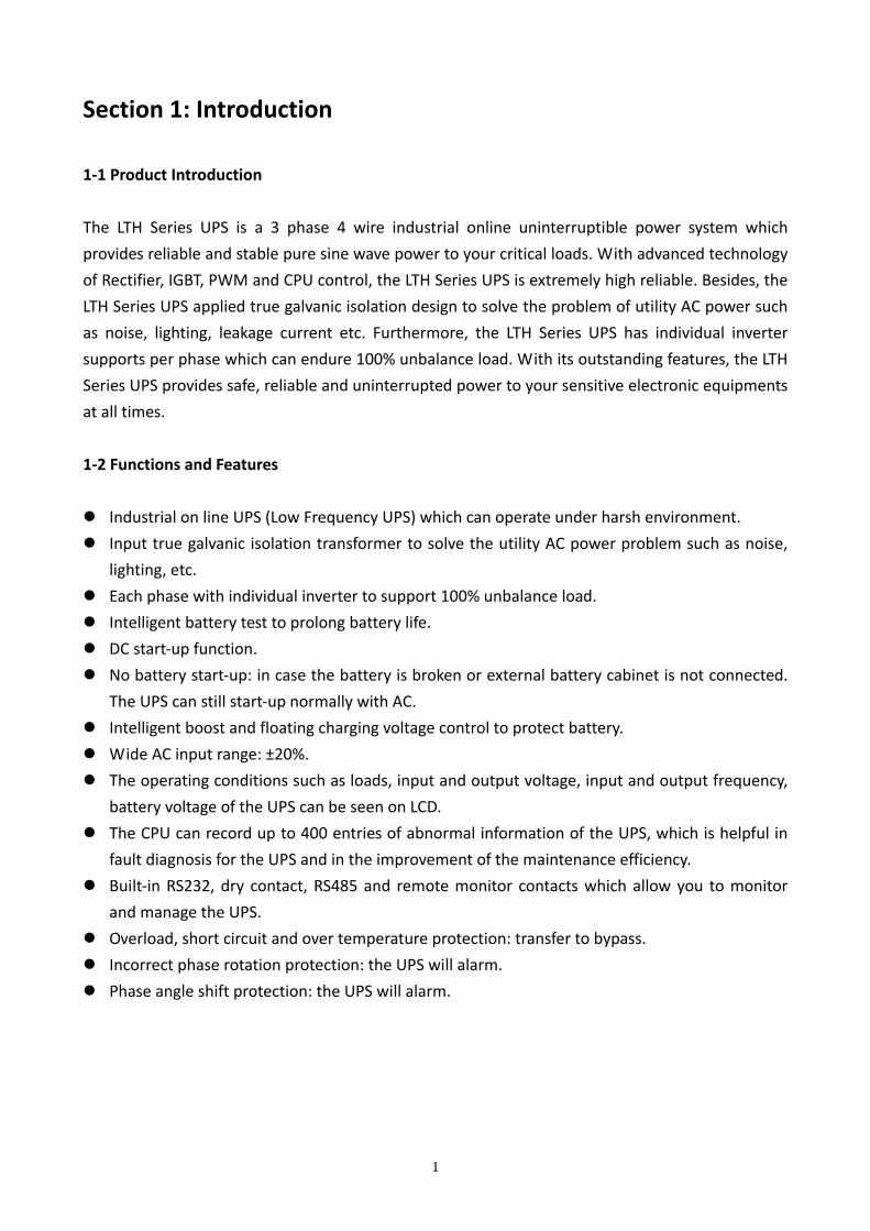
The LTH Series UPS is a 3 phase 4 wire industrial online uninterruptible power system which
provides reliable and stable pure sine wave power to your critical loads. With advanced technology
of Rectifier, IGBT, PWM and CPU control, the LTH Series UPS is extremely high reliable. Besides, the
LTH Series UPS applied true galvanic isolation design to solve the problem of utility AC power such
as noise, lighting, leakage current etc. Furthermore, the LTH Series UPS has individual inverter
supports per phase which can endure 100% unbalance load. With its outstanding features, the LTH
Series UPS provides safe, reliable and uninterrupted power to your sensitive electronic equipments
at all times.
1‐2 Functions and Features
Industrial on line UPS (Low Frequency UPS) which can operate under harsh environment.
Input true galvanic isolation transformer to solve the utility AC power problem such as noise,
lighting, etc.
Each phase with individual inverter to support 100% unbalance load.
Intelligent battery test to prolong battery life.
DC start‐up function.
No battery start‐up: in case the battery is broken or external battery cabinet is not connected.
The UPS can still start‐up normally with AC.
Intelligent boost and floating charging voltage control to protect battery.
Wide AC input range: ±20%.
The operating conditions such as loads, input and output voltage, input and output frequency,
battery voltage of the UPS can be seen on LCD.
The CPU can record up to 400 entries of abnormal information of the UPS, which is helpful in
fault diagnosis for the UPS and in the improvement of the maintenance efficiency.
Built‐in RS232, dry contact, RS485 and remote monitor contacts which allow you to monitor
and manage the UPS.
Overload, short circuit and over temperature protection: transfer to bypass.
Incorrect phase rotation protection: the UPS will alarm.
Phase angle shift protection: the UPS will alarm.
1
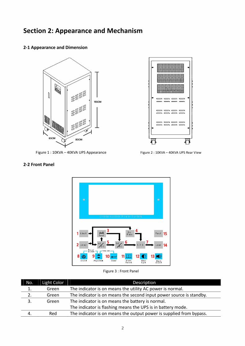
Section 2: Appearance and Mechanism 2‐1 Appearance and Dimension
Figure 1 : 10KVA – 40KVA UPS Appearance Figure 2 : 10KVA – 40KVA UPS Rear View
2‐2 Front Panel
Figure 3 : Front Panel
No. Light Color Description 1. Green The indicator is on means the utility AC power is normal. 2. Green The indicator is on means the second input power source is standby. 3. Green The indicator is on means the battery is normal.
The indicator is flashing means the UPS is in battery mode. 4. Red The indicator is on means the output power is supplied from bypass.
2

No. Light Color Description 5. Green The indicator is on means the rectifier and charger is operating normal. 6. Green The indicator is on means the IGBT and inverter is operating normal. 7. Green The indicator is on means the static transfer switch is operating normal. 8. N/A Press “8” and “9” buttons together to turn on / turn off the UPS. 9. N/A Press this button to change the UPS status pages.
Press this button to change ‐ in setting page. 10. N/A Press “9” and “10” buttons together to set date and time.
Press this button to confirm the setting ‐ in setting page. 11. N/A Press this button to see the event logs of the UPS.
Press “11” and “12” buttons together to set language. 12. N/A Press this button to light the LCD backlight. 13. N/A Press this button to mute alarm. 14. Green The indicator is on means the load is in using. 15. Red The indicator is on means the UPS is abnormal.
2‐3 Front Door Opened
Figure 4 : Front Door Opened No. Description 1. N.F.B.s protective cover. 2. Maintenance bypass N.F.B. protective cover. 3. Signal control PCB protective cover. 4. LCM control PCB / LCD PCB / LED PCB protective cover. 5. Cable through hole. 6. Communication PCB. 7. User manual leaving. 8. Battery input N.F.B. 9. Mains input N.F.B. 10. Bypass (Reserve) input N.F.B.
11. Maintenance bypass N.F.B. For maintenance only! Only qualified and trained technician can open the cover plate of Maintenance bypass N.F.B. and operate it.
12. Output N.F.B.
3

No. Description 13. External battery bank input terminal block. 14. Utility AC power Input terminal block. 15. Output terminal block.
4

Section 3: System Description 3‐1 UPS Block Diagram
Figure 5 : UPS Block Diagram
Figure 5: UPS Block Diagram demonstrates the UPS working principle briefly. The utility AC power pass through the Input ISO Transformer to eliminate noise, leakage current, surge, etc, then the 6 Pulse Rectifier converts AC to DC to provide DC power for Charger to charge the battery and provide DC power for IGBT to trigger PWM to convert DC to AC. After PWM converts DC to AC, then AC will pass through the Inverter and provides reliable and stable pure sine wave power for the loads. In the event of overload or the UPS failure, the STS will work and allows the utility AC power provides power for loads directly. 3‐2 Input Isolation Transformer Block Diagram
Figure 6 : Input Isolation Transformer Block Diagram
Figure 6: Input Isolation Transformer Block Diagram demonstrates the Input Isolation Transformer working principle briefly. The Input Isolation Transformer is designed to eliminate noise, surge, leakage current of the utility AC power to protect the components of the UPS and provide clean AC power for the 6 Pulse Rectifier.
5

3‐3 6 Pulse Rectifier Block Diagram
Figure 7 : Rectifier Block Diagram
Figure 7: Rectifier Block Diagram demonstrates the 6 Pulse Rectifier working principle briefly. The 6 Pulse Rectifier is designed to convert AC to DC to provide DC power for Charger to charge the battery and provide DC power for IGBT to trigger PWM to convert DC to AC. 3‐4 IGBT and PWM Block Diagram
Figure 8 : IGBT and PWM Block Diagram
Figure 8: IGBT and PWM Block Diagram demonstrates the IGBT and PWM working principle briefly. The IGBT and PWM are designed to convert DC power to AC power. The DC power converted by Rectifier powers the IGBT to trigger the PWM to convert DC power to AC power. 3‐5 3 Phase Inverter Block Diagram
Figure 9 : Inverter Block Diagram
Figure 9: Inverter Block Diagram demonstrates the Inverter working principle briefly. The AC power converted by PWM passes through the Inverter then goes through the STS to the loads.
6

3‐6 STS Block Diagram
Figure 10 : STS Block Diagram
Figure 10: STS Block Diagram demonstrates the STS working principle briefly. The STS is designed to control the output AC power whether goes through the Inverter or directly from the utility AC power. If the UPS is normal, the output AC power will go through the Inverter and provide power for loads. If the UPS is failure or overload or over temperature, the loads will be provided by the utility AC power.
7

Section 4: Installation and Wiring 4‐1 Prior to Installation
Only a qualified and trained technician can do the installation. If you want to install by
yourself, installation must be under the supervision of qualified and trained technician.
During the transportation, some unpredictable situations might occur. It is
recommended that you inspect the UPS exterior packaging. If you notice any damage,
please immediately contact the dealer from whom you purchased the UPS.
Open the front door to check the rating label on the UPS and make sure the model
number, capacity and specification of the UPS match what you purchased.
During the transportation, some unpredictable situations might occur. It is
recommended that you check the UPS can be turned on normally or not. Please follow
below procedures:
1. Open front door and check five N.F.B.s (see Figure 4) are at「OFF」position. 2. Switch on「8. Battery Input N.F.B.」(see Figure 4). * Note: If check 40KVA UPS, please connects external battery bank first. Please refer to 4‐6 External Battery Bank Wiring.
3. Then press「8. On/Off」and「9. Page/Shift」buttons (see Figure 3) together and release
after you hear a beep to turn on the UPS. 4. If the UPS is fault,「15. Fault」indicator (see Figure 3) will light and alarm continuously.
Please immediately contact the dealer from whom you purchased the UPS.
5. If the UPS is normal, then press「8. On/Off」 and 「9. Page/Shift」 buttons (see Figure
3) together and release after you hear a beep to turn OFF the UPS.
6. Switch off「8. Battery Input N.F.B.」and check again five N.F.B.s (see Figure 4) are at
「OFF」position then start to install the UPS. 4‐2 Installation Environment
Install the UPS indoors. Do not place the UPS outdoors.
Make sure the installation area can accommodate and bear the weight of the UPS and
external battery cabinets.
The installation place must be kept clean and tidy at all times.
Make sure the installation area is big enough for maintenance and ventilation. Since the
fans of the UPS ventilate to rear and it is recommended that you place the external
battery cabinet next the UPS. We suggest you:
Keep a distance of 100cm from the front of the UPS and the external battery cabinet
for maintenance and ventilation.
8
Keep a distance of 50cm from the back of the UPS and the external battery cabinet for
maintenance and ventilation.
Keep a distance of 50cm from the both sides of the UPS and the external battery
cabinet for maintenance and ventilation.
Keep the installation area temperature around 15 ゚ C ‐ 25 ゚ C to prolong the battery life.
4‐3 Prior to Wiring
Only a qualified and trained technician can do the wiring. If you want to wire by yourself,
wiring must be under the supervision of qualified and trained technician.
Please make sure the five N.F.B.s (see Figure 4) are at「OFF」position.
Please check whether the utility AC power voltage, frequency, phase and wire match the
UPS that you purchased or not.
If the external battery bank needs to be connected to the UPS, please make sure the
number of batteries of the external battery bank must meet UPS specification. Please
refer to 4‐6 External Battery Bank Wiring.
A battery can present a risk of electric shock and high short circuit current. Servicing of
batteries and external battery bank must be performed or supervised by qualified and
trained technician knowledgeable in batteries and external battery bank. Keep
unauthorized personnel away from batteries and the external battery bank.
Please make sure the power that will be supplied to the external battery terminal block
and input terminal block (see Figure 4) of the UPS are completely cut off.
Please check whether the loads connected to the UPS exceed the capacity of the UPS or
not.
If the UPS needs to be connected to a motor load, it must be confirmed by qualified and
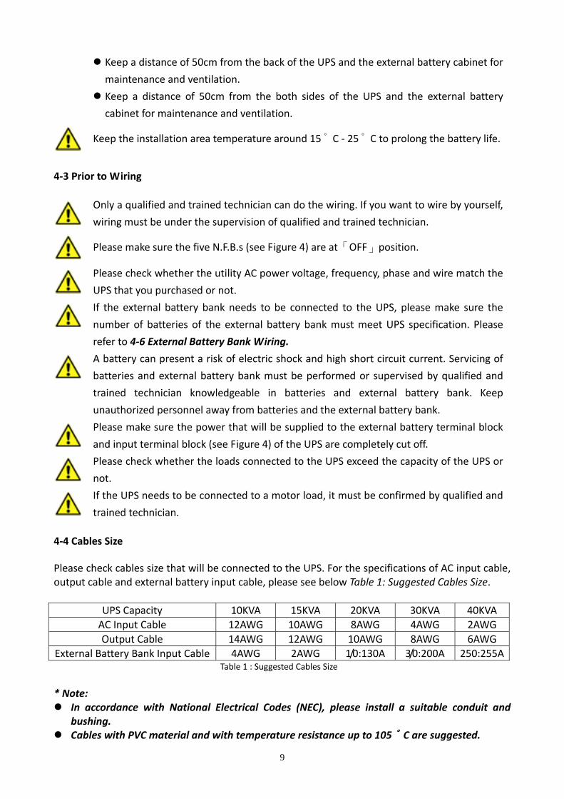
trained technician. 4‐4 Cables Size Please check cables size that will be connected to the UPS. For the specifications of AC input cable, output cable and external battery input cable, please see below Table 1: Suggested Cables Size.
UPS Capacity 10KVA 15KVA 20KVA 30KVA 40KVA AC Input Cable 12AWG 10AWG 8AWG 4AWG 2AWG Output Cable 14AWG 12AWG 10AWG 8AWG 6AWG
External Battery Bank Input Cable 4AWG 2AWG 1/0:130A 3/0:200A 250:255ATable 1 : Suggested Cables Size
* Note:
In accordance with National Electrical Codes (NEC), please install a suitable conduit and bushing.
Cables with PVC material and with temperature resistance up to 105 ゚ C are suggested.
9

4‐5 Wiring
1 2 3
Figure 11 : Wiring Terminal Blocks
No. Description Function 1 External battery bank input terminal block. Connects the mains AC source. 2 Utility AC power input terminal block. Connects an external battery bank. 3 Output terminal block. Connects the loads.
* Note:
Incorrect wiring will lead to severe electric shock and damage to the UPS. The utility AC power must be three phase (R/S/T) and meet the specification specified on the UPS rating label. When connecting the utility AC power to the UPS, make sure the phase sequence is correct.
When connecting the external battery bank to the UPS, do not reverse the polarity. Make sure that all the cables are screwed tightly.
4‐6 External Battery Bank Wiring Our standard 10KVA / 15KVA / 20KVA / 30KVA UPS can be installed 12VDC * 16pcs batteries internal (Max. 12VDC 40Ah * 16pcs can be placed). Our standard 40KVA UPS can not be installed 12VDC * 16pcs batteries internal. The 40KVA UPS must have external battery bank. If you want to extend battery backup time for 10KVA / 15KVA / 20KVA / 30KVA UPS or connect external battery bank to 40KVA UPS, please make sure:
The number of batteries of the external battery bank must be 12VDC * 16pcs. Only use the same type of batteries from the same supplier. Never use old, new and different Ah batteries at the same time.
10

Do not connect the batteries in reverse. Please contact the dealer from whom you purchased the UPS to confirm whether the charging current of the battery charger is sufficient or not.
The external battery bank must have N.F.B.
11

Section 5: Communication Interface Figure 12 : Communication Interface
5‐1 RS232
Hardware Pin Assignment Baud Rate: 2400bps PIN 2: RXD (Receiving Data) Data Length: 8 bit PIN 3: TXD (Transmitting Data) Stop Bit: 1 bit PIN 5: GND (Ground)
Parity: None RS232 port is to provide communication between the UPS and a computer. The UPS will provide information such as the UPS operation mode, battery capacity, battery voltage, UPS input/output voltage, UPS input/output frequency, etc… for you to check and monitor the UPS status via a computer. An option accessory: RS232‐SNMP Adapter (Please refer to 11‐3 RS232‐SNMP Adapter) is available as well for you to monitor the UPS via Internet. 5‐2 Dry Contact
Pin Assignment PIN 1: Bypass PIN 6: Shutdown PIN 2: Utility AC power Failure (N.O.) PIN 7: Shutdown PIN 3: Utility AC power Failure (N.C.) PIN 8: Any Alarm PIN 4: Ground PIN 9: UPS Failure
PIN 5: Battery Low Dry Contact is to provide UPS status such as bypass mode, battery mode, battery low voltage, any alarm and any fault of the UPS for you to know the UPS status immediately. The Dry Contact can also let you shutdown the UPS remotely. Right side figure demonstrates how you should make the connection for remote monitor.
12
5‐3 RS485 (need optional accessory: RS485‐RS232 adapter)
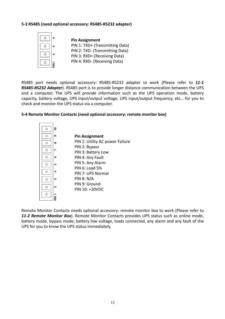
Pin Assignment PIN 1: TXD+ (Transmitting Data) PIN 2: TXD‐ (Transmitting Data) PIN 3: RXD+ (Receiving Data) PIN 4: RXD‐ (Receiving Data)
RS485 port needs optional accessory: RS485‐RS232 adapter to work (Please refer to 11‐1 RS485‐RS232 Adapter). RS485 port is to provide longer distance communication between the UPS and a computer. The UPS will provide information such as the UPS operation mode, battery capacity, battery voltage, UPS input/output voltage, UPS input/output frequency, etc… for you to check and monitor the UPS status via a computer. 5‐4 Remote Monitor Contacts (need optional accessory: remote monitor box)
Pin Assignment PIN 1: Utility AC power Failure PIN 2: Bypass PIN 3: Battery Low PIN 4: Any Fault PIN 5: Any Alarm PIN 6: Load 5% PIN 7: UPS Normal PIN 8: N/A PIN 9: Ground PIN 10: +20VDC
Remote Monitor Contacts needs optional accessory: remote monitor box to work (Please refer to 11‐2 Remote Monitor Box). Remote Monitor Contacts provides UPS status such as online mode, battery mode, bypass mode, battery low voltage, loads connected, any alarm and any fault of the UPS for you to know the UPS status immediately.
13

Section 6: Operation and Operation Modes 6‐1 Turn ON the UPS After you finished UPS installation and wiring, please see below procedures to turn ON the UPS: 1. Make sure the loads connected to the UPS are turn OFF. 2. Open front door and check five N.F.B.s (see Figure 4) are at「OFF」position. 3. Make sure the utility AC power N.F.B. and external battery bank N.F.B. (if you have external
battery bank) are switch「ON」. 4. Switch ON「8. Battery Input N.F.B.」(see Figure 4) and you will hear a short beep. The indicators
will light and LCD will show as Figure 13.
Figure 13 : LCD and Indicators ‐ 1
5. Switch ON「9. Mains Input N.F.B.」(see Figure 4). The indicators will light and LCD will show as Figure 14.
Figure 14 : LCD and Indicators ‐ 2
14

6. Switch ON「10. Bypass (Reserve) Input N.F.B.」(see Figure 4). The indicators and LCD remain as Figure 14.
7. Switch ON「12. Output N.F.B.」(see Figure 4). Be careful that the output has power from the
utility AC power now. The indicators and LCD remain as Figure 14. 8. Press 「8. On/Off」and「9. Page/Shift」 buttons (see Figure 3) together and release after you
hear a beep to turn ON the UPS. The indicators will light and LCD will show as Figure 15.
Figure 15 : LCD and Indicators ‐ 3
* Note: If the UPS beep continuously and LCD show as Figure 31 or Figure 32, please check the utility AC power input wiring phase rotation or phase angle.
9. The UPS is working now and you can turn ON your loads. 6‐2 Turn OFF the UPS If you want to turn OFF the UPS, please see below procedures to turn OFF the UPS: 1. Make sure the loads connected to the UPS are turn OFF. 2. Press 「8. On/Off」and「9. Page/Shift」 buttons (see Figure 3) together and release after you
hear a beep to turn OFF the UPS. Be careful that the output still has power from the utility AC power.
3. Switch OFF「12. Output N.F.B.」(see Figure 4). 4. Switch OFF「10. Bypass (Reserve) Input N.F.B.」(see Figure 4). 5. Switch OFF「9. Mains Input N.F.B.」(see Figure 4). 6. Switch OFF「8. Battery Input N.F.B.」(see Figure 4). 7. The UPS is completely turn OFF now.
15
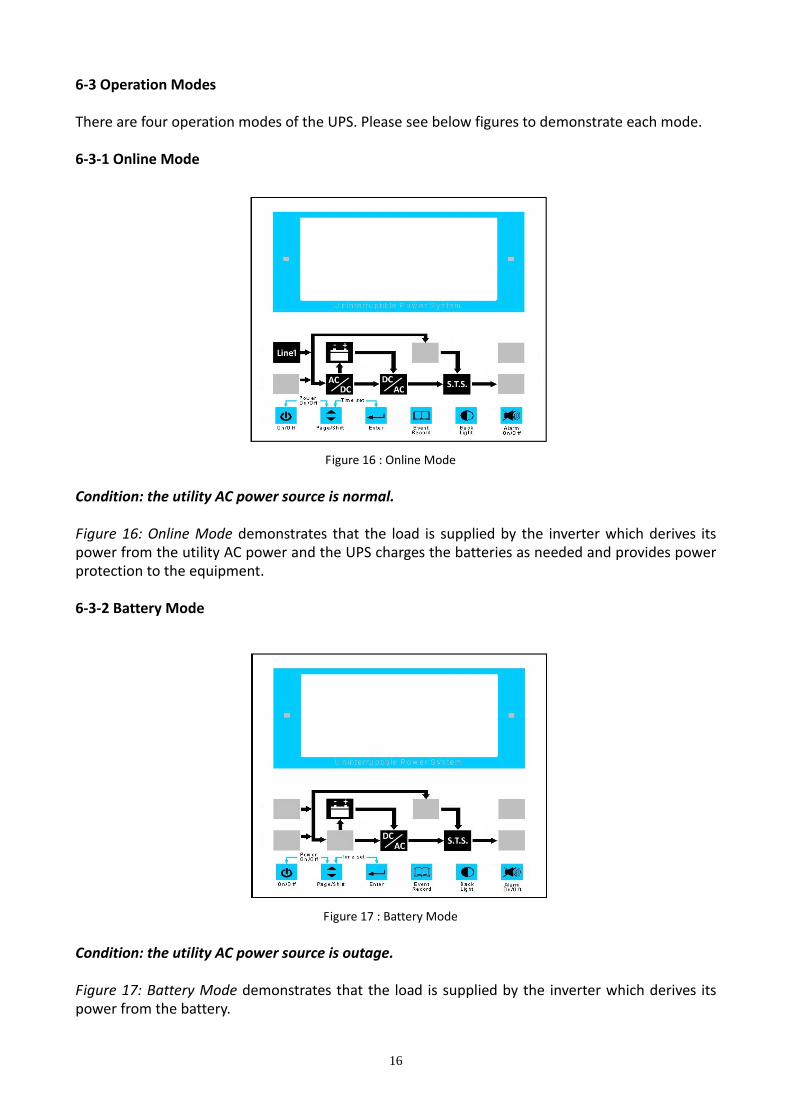
6‐3 Operation Modes There are four operation modes of the UPS. Please see below figures to demonstrate each mode. 6‐3‐1 Online Mode
Figure 16 : Online Mode Condition: the utility AC power source is normal. Figure 16: Online Mode demonstrates that the load is supplied by the inverter which derives its power from the utility AC power and the UPS charges the batteries as needed and provides power protection to the equipment. 6‐3‐2 Battery Mode
Figure 17 : Battery Mode Condition: the utility AC power source is outage. Figure 17: Battery Mode demonstrates that the load is supplied by the inverter which derives its power from the battery.
16

6‐3‐3 Bypass Mode
Figure 18 : Bypass Mode Condition: over temperature or overload or UPS shutdown or UPS failure. Figure 18: Bypass Mode demonstrates that the load is supplied by the utility AC power, not the inverter, and the batteries are charged. 6‐3‐4 Maintenance Bypass Mode Condition: the UPS needed to be repaired by a qualified and trained technician. Maintenance bypass is designed to supply the utility AC power to the loads directly when there is a fault condition on the UPS and maintenance work needs to be carried out. This operation must only be carried out by a qualified and trained technician who is familiar with the LTH series UPS. Incorrect use of the Maintenance Bypass N.F.B. can cause severe damage to the UPS.
17

Section 7: LCD Display and Setting 7‐1 UPS Status Screen After you turn ON the UPS, the LCD will show status of the UPS. There are four pages and you can press「9. Page/Shift」button (see Figure 3) to change the page. Each page is as below figure:
Figure 19 : Input Status Screen Figure 19: Input Status Screen demonstrates the utility AC power R/S/T input voltage and frequency.
Figure 20 : Output Status Screen Figure 20: Output Status Screen demonstrates the UPS R/S/T output voltage and frequency.
18

Figure 21 : Load Status Screen Figure 21: Load Status Screen demonstrates the UPS R/S/T loads percentage, current and UPS interior temperature.
Figure 22 : Battery Status Screen Figure 22: Battery Status Screen demonstrates the battery voltage, battery capacity, battery discharge current and charging current.
19
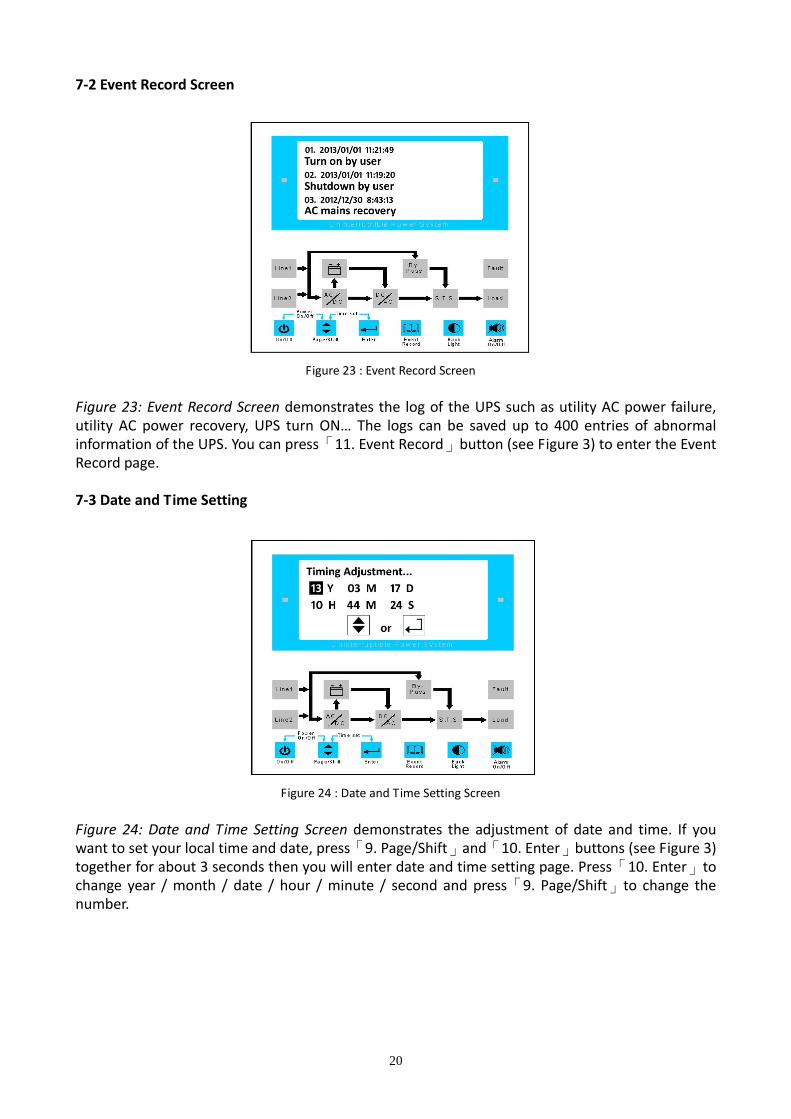
7‐2 Event Record Screen
Figure 23 : Event Record Screen Figure 23: Event Record Screen demonstrates the log of the UPS such as utility AC power failure, utility AC power recovery, UPS turn ON… The logs can be saved up to 400 entries of abnormal information of the UPS. You can press「11. Event Record」button (see Figure 3) to enter the Event Record page. 7‐3 Date and Time Setting
Figure 24 : Date and Time Setting Screen Figure 24: Date and Time Setting Screen demonstrates the adjustment of date and time. If you want to set your local time and date, press「9. Page/Shift」and「10. Enter」buttons (see Figure 3) together for about 3 seconds then you will enter date and time setting page. Press「10. Enter」to change year / month / date / hour / minute / second and press「9. Page/Shift」to change the number.
20

7‐4 Language Setting
Figure 25 : Language Setting Screen Figure 25: Language Setting Screen demonstrates the adjustment of language. Press「11. Event Record」and「12. Back Light」buttons (see Figure 3) together for about 3 seconds then you will enter language setting page. Press「9. Page/Shift」to select the language and press「10. Enter」to confirm.
21

Section 8: Abnormal Events LCD Display 8‐1 Utility AC Power Source Outage Screen
Figure 26 : Utility AC Power Source Outage Screen If the utility AC power source is failure, the UPS will beep, the screen will flash and the screen will have warning message as Figure 26 shown. 8‐2 Utility AC Power Voltage too High Screen
Figure 27 : Utility AC Power Voltage too High Screen If the utility AC power source voltage is too high, the screen will flash and the screen will have warning message as Figure 27 shown.
22

8‐3 Output Short Circuit Screen
Figure 28 : Output Short Circuit Screen If output short circuit, the UPS will beep continuously and the screen will have warning message as
Figure 28 shown. Then the UPS will transfer to bypass mode. 8‐4 Overload Screen (100% ‐ 124%)
Figure 29 : Overload Screen (100% ‐ 124%) If overload 100% ‐ 124% (any phase), the UPS will beep continuously, the screen will flash and the
screen will show as Figure 29. After 10 minutes, the UPS will transfer to bypass mode.
23
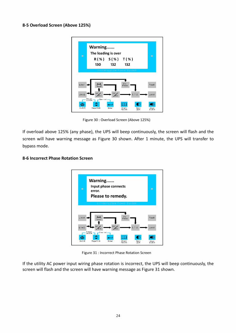
8‐5 Overload Screen (Above 125%)
Figure 30 : Overload Screen (Above 125%) If overload above 125% (any phase), the UPS will beep continuously, the screen will flash and the
screen will have warning message as Figure 30 shown. After 1 minute, the UPS will transfer to
bypass mode. 8‐6 Incorrect Phase Rotation Screen
Figure 31 : Incorrect Phase Rotation Screen If the utility AC power input wiring phase rotation is incorrect, the UPS will beep continuously, the screen will flash and the screen will have warning message as Figure 31 shown.
24
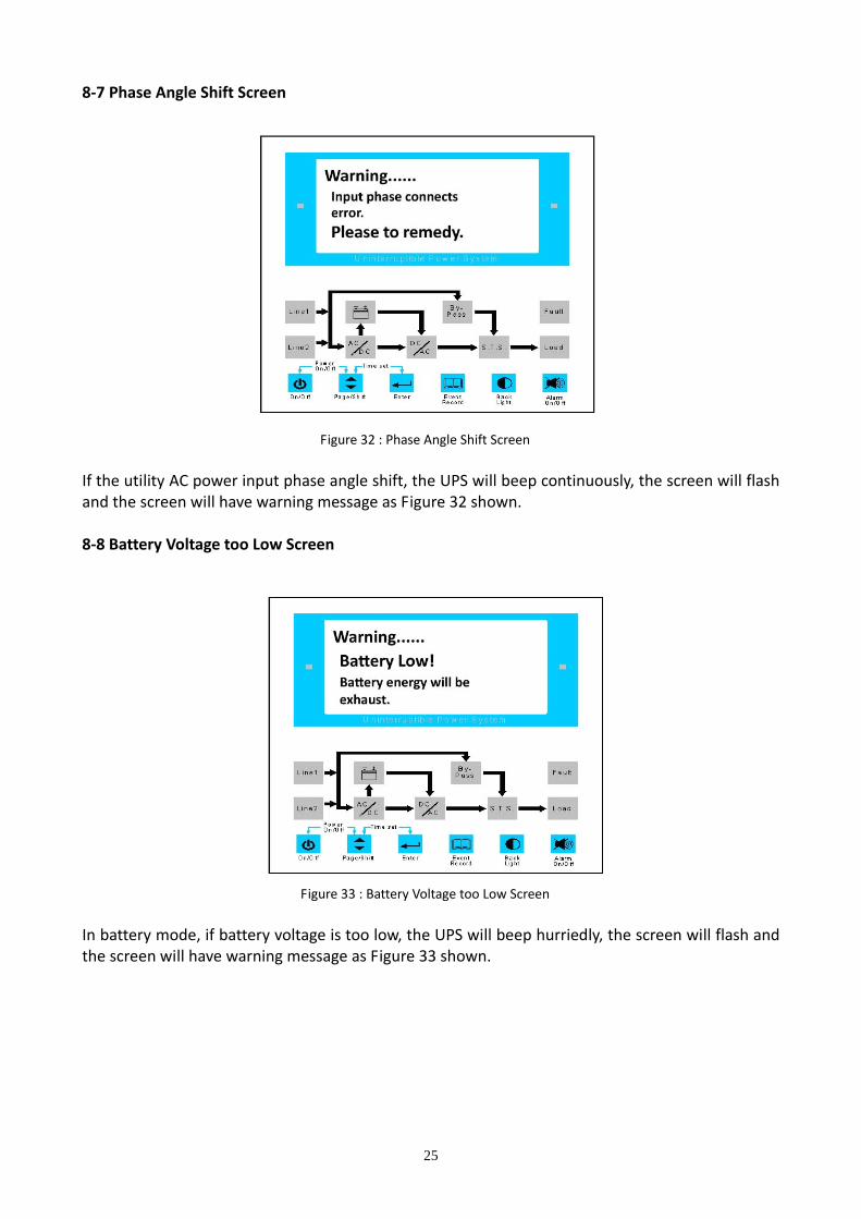
8‐7 Phase Angle Shift Screen
Figure 32 : Phase Angle Shift Screen If the utility AC power input phase angle shift, the UPS will beep continuously, the screen will flash and the screen will have warning message as Figure 32 shown. 8‐8 Battery Voltage too Low Screen
Figure 33 : Battery Voltage too Low Screen In battery mode, if battery voltage is too low, the UPS will beep hurriedly, the screen will flash and the screen will have warning message as Figure 33 shown.
25
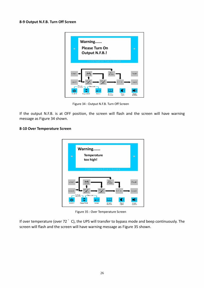
8‐9 Output N.F.B. Turn Off Screen
Figure 34 : Output N.F.B. Turn Off Screen If the output N.F.B. is at OFF position, the screen will flash and the screen will have warning message as Figure 34 shown. 8‐10 Over Temperature Screen
Figure 35 : Over Temperature Screen If over temperature (over 72 ゚ C), the UPS will transfer to bypass mode and beep continuously. The screen will flash and the screen will have warning message as Figure 35 shown.
26
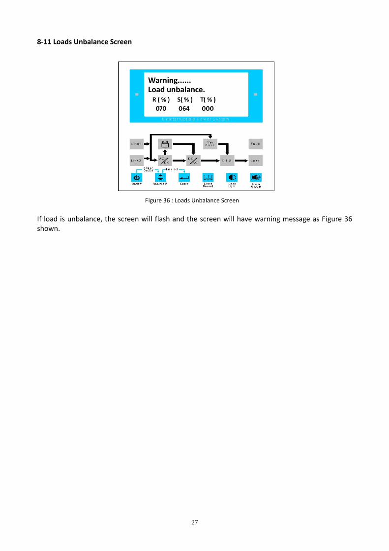
8‐11 Loads Unbalance Screen
Figure 36 : Loads Unbalance Screen If load is unbalance, the screen will flash and the screen will have warning message as Figure 36 shown.
27

Section 9: Trouble Shooting When you see the following problems on the LCD, please follow the solutions shown below. No. Warning Message Possible Cause Solution 1. Input voltage too
high Utility AC power input voltage is too high
Contact service personnel
2. UPS output short Output has a short circuit issue Contact service personnel 3. The loading is over The UPS is overload Remove some loads 4. Input phase
connects error 1. Input wiring phase rotation is
incorrect 2. Input phase angle shift
1. Cutoff the utility AC power N.F.B. first
2. Turn off the UPS 3. Check input R.S.T. sequence 4. Contact service personnel
5. Battery low Battery voltage is low Charge the batteries 6. Please turn on
output N.F.B. Output N.F.B. is at off position
Switch on output N.F.B.
7. Temperature too high
The UPS temperature is too high
1. Choose a well‐ventilated area 2. Decrease some loads 3. Check if fans run normally
8. Load unbalance 1. The loads center on one or two phase
2. Output wiring does not connect well
1. Average loads of each phase 2. Check output wiring 3. Contact service personnel
28
Section 10: Maintenance 10‐1 UPS Check the UPS quarterly and inspect:
Whether the UPS, LCD, LED and alarm function are operating normally. Whether the UPS works in bypass mode (normally the UPS will work in online mode). If yes, check if any error, overload, internal fault, etc. occurs.
Whether battery voltage is normal. If the battery voltage is too high or too low, find the root cause.
UPS Cleaning: Regularly clean the UPS, especially the slits and openings, to ensure that the air freely flows into
the UPS to avoid overheating. If necessary, use an air‐gun to clean the slits and openings to prevent
any object from blocking or covering these areas. 10‐2 Battery The LTH Series UPS uses sealed lead acid batteries. The battery life depends on the temperature,
the usage, and the charging/discharging frequency. High temperature environments and high
charging/discharging frequency will quickly shorten the battery life. Please follow the suggestions
below to ensure a normal battery lifetime.
Keep usage temperature between 15 ゚ C ‐ 25 ゚ C When the UPS needs to be stored for an extended period of time, the batteries must be recharged once every three months and the charging time must be less than 24 hours each time.
10‐3 Fan Higher temperatures shorten fan life. When the UPS is running, please check if all fans work
normally and make sure if the ventilation air can move freely around and through the UPS. If not,
replace the fans. * Note:
Please ask your local dealer for more maintenance information. Do not perform maintenance if you are not trained for it.
29
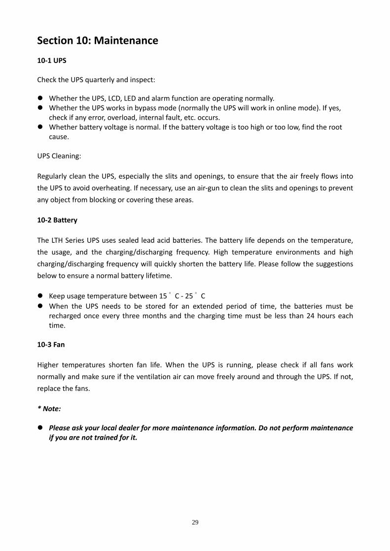
Section 11: Optional Accessories 11‐1 RS485‐RS232 Adapter
RS485‐RS232 Adapter converts RS485 signal to RS232 signal and allows you to connect to a computer to monitor the UPS status, such as operation mode, battery capacity, battery voltage, UPS input/output voltage, UPS input/output frequency, etc. 11‐2 Remote Monitor Box
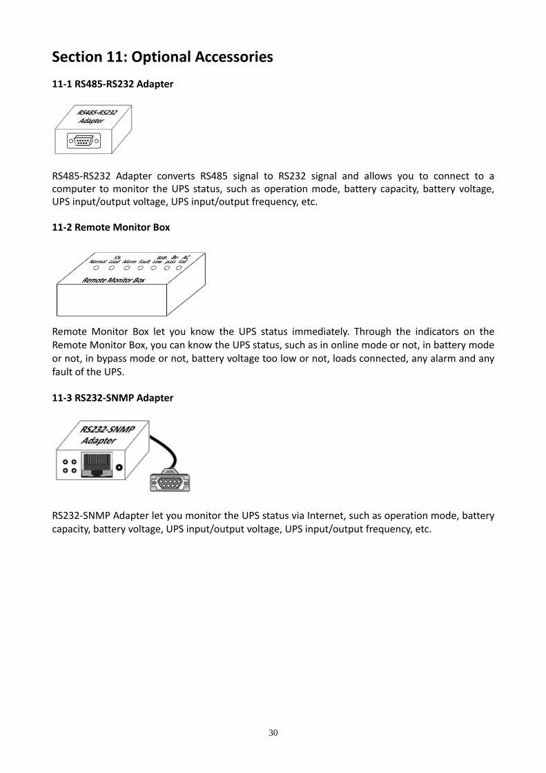
Remote Monitor Box let you know the UPS status immediately. Through the indicators on the Remote Monitor Box, you can know the UPS status, such as in online mode or not, in battery mode or not, in bypass mode or not, battery voltage too low or not, loads connected, any alarm and any fault of the UPS. 11‐3 RS232‐SNMP Adapter
RS232‐SNMP Adapter let you monitor the UPS status via Internet, such as operation mode, battery capacity, battery voltage, UPS input/output voltage, UPS input/output frequency, etc.
30

Section 12: Specification
Model LTH‐3110 LTH‐3115 LTH‐3120 LTH‐3130 LTH‐3140 Capacity 10KVA 15KVA 20KVA 30KVA 40KVA
Voltage 3 Phase 4 Wire + G 220/380VAC, 230/400VAC, 240/415VAC Voltage Range ± 20% (option : >20%) Frequency 50Hz or 60Hz
Input
Frequency Range ± 5% Voltage 3 Phase 4 Wire + G 220/380VAC, 230/400VAC, 240/415VAC
Frequency 50Hz or 60Hz ± 0.5% Static Regulation ± 1% at linear load
Dynamic Regulation <=2% at 50% unbalance load, <=5% at 100% unbalance load THD Distortion <=3% at linear load, <=5% at non‐linear load
Transient Response <5ms
Output
Power Factor 0.8 Voltage 192VDC (12VDC * 16pcs)
Charge Current As customer demand Float Charging Voltage 216VDC Boost Charging Voltage 227VDC
Battery
Recharge Time 4 ~ 8 hours to 90% after fully discharge Static Switch Main <‐> Inverter No break
LCD Display Input / Output Voltage, Input / Output Frequency, Output Loading Status,
Battery Status, Event Record Indicator LED Display Mimic display Overload 100% ~124% for 10 minutes, >125% for 1 minute, >150% to bypass
Over Temperature Yes Phase Rotation Incorrect Yes
Phase Angle Shift Yes Protection
Lighting/EMI Filter Yes Temperature 0 ゚ C ~ 40 ゚ C Humidity 0% ~ 95%, non‐condensing Environment Noise Level <65dB at 1 meter
Communication Interface Port RS232, Dry Contact, RS485, Remote Monitor Contacts
RS485‐RS232 Adapter (option), Remote Monitor Box (option), RS232‐SNMP Adapter (option)
Dimension (W * D * H)
UPS Only (cm) 65 * 80 * 155
Net Weight UPS Only (kgs) 250 300 350 400 450
31

Section 13: Warranty Seller warrants this product for a period of 1 YEAR from the date of shipment, if used in
accordance with all applicable instruction, to be free from original defects in material and
workmanship within the warranty period. If the product has any failure problem within the
warranty period, Seller will repair or replace the product as its sole discretion according to the
failure situation.
This warranty does not apply to normal wear or to damage resulting from importer installation,
operation, usage, maintenance or irresistible force (i.e. war, fire, natural disaster, etc.), and this
warranty also expressly excludes all incidental and consequential damages.
Maintenance service for a fee is provided for any damage out of the warranty period. If any maintenance is required, please directly contact with the supplier or Seller.
32