Embed Size (px)
Citation preview
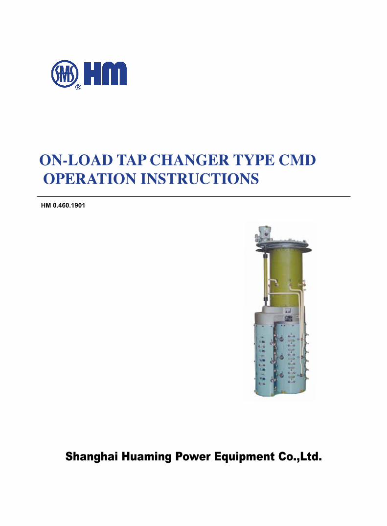
Shanghai Huaming Power Equipment Co.,Ltd.
ON-LOAD TAP CHANGER TYPE CMD OPERATION INSTRUCTIONSHM 0.460.1901
1
ON-LOAD TAP CHANGER TYPE CMDOperation Instructions
HM 0.460.1901
1. Brief Introduction…………………………………………………………………………………………2
2.Structure Of type CMD OLTC…………………………………………………………………………7
3. Operating Principle………………………………………………………………………………………10
4. Installation Method of CMD On Load Tap Changer (For Bell Type)…………………………………12
5. Operation Supervision…………………………………………………………………………………21
6. Whole Set Supply Range………………………………………………………………………………22
7. Maintenance and Repair………………………………………………………………………………23
8. Appendix …………………………………………………………………………………………………27
Contents
2
CMD type of OLTC, an hi-tech product solely developed by HM Grp Ltd through technological
innovation and constant efforts for past decades, not only maintains its original parts and structure,
which qualified through practical operation for so many years, in addition to HM's unique design,
but eventually enhances its reliability for long-time endurance.
The Highest Equipment Voltage of CMD On Load Tap Changer (OLTC) is 252KV. Three-phase
CMD OLTC is applicable for transformers with highest equipment voltage up to 550KV or less with
neutral point regulation. Single phase CMD OLTC is applicable to any connections. The maximum
rated through current of three-phase CMD can reach 1000A. 2400A is for single phase. It is to
regulate the voltage on load by changing the taps. The maximum operating position of CMD OLTC
is 35 (with change-over selector).
CMD OLTC is a combined type OLTC, which consists of 2 main parts: diverter switch and tap
selector.
1. Brief Introduction
Fig 1. Outline view of CMD OLTC
ON-LOAD TAP CHANGER TYPE CMDOperation Instructions
HM 0.460.1901
3
a. 10090 – Number of contacts in circle pitch selector for 1 phase is 10, maximum operating
position is 9, and 0 represents a linear OLTC without change-over selector.
b. 10193W – Number of contacts in circle pitch selector for 1 phase is 10, maximum operating
position is 19 and a mid position is 3. W represents an OLTC with reversing change-over selector.
c. 10191G – Number of contacts in circle pitch selector for 1 phase is 10, maximum operating
position is 19 and a mid position is 3. G represents an OLTC with coarse change-over selector.
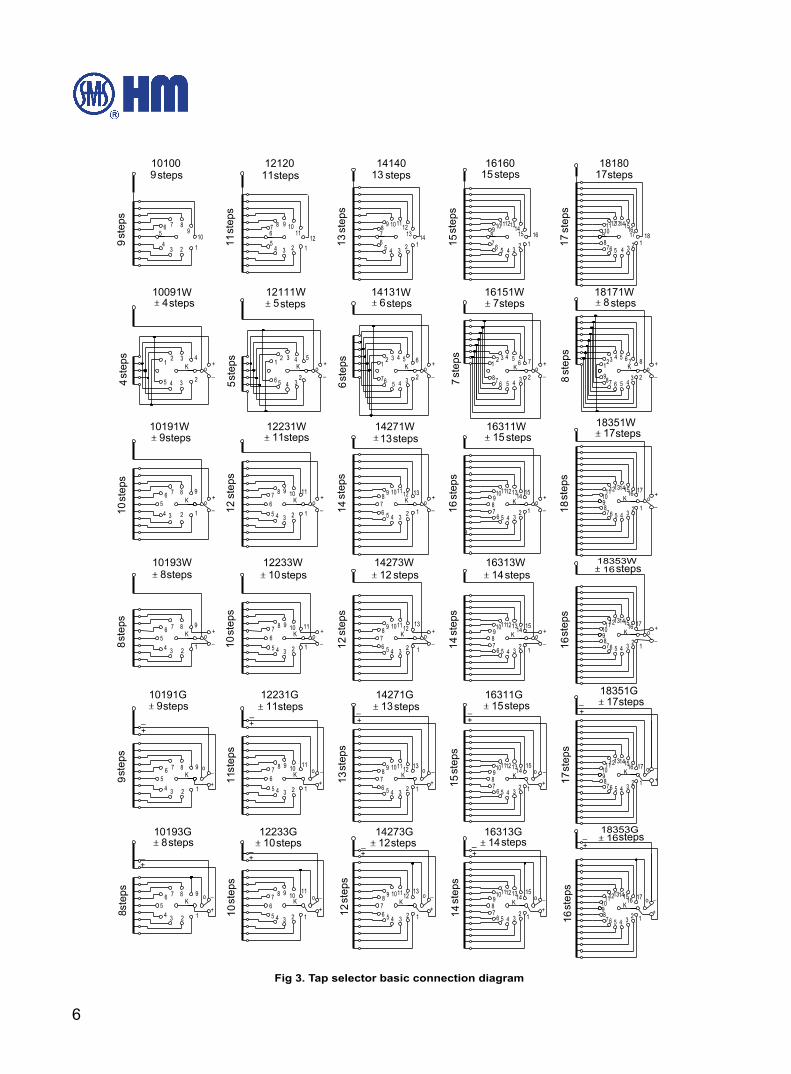
1.1.2 Insulation Level of Tap Selector
The insulation for the tap selector can be classified into 4 different insulation grades, namely B, C, D,
DE. Table 1 shows the data of the internal insulation level. The basic connection drawings and the
code for insulation distance shows in Fig. 2.
Change-over selector,
represented by W, G
Number of Mid-Position
Operation Positions
Number of Contact Pitch (1 Phase)
Tap Selector size
Highest voltage for equipment (KV)
Maximum Rated Through Current (A)
Number of Phase
Type No.
W:reversing,
0: linear,
G:coarse & fine
CMD □- □ /□ □ -□ □ □ □
CMD OLTC will be mounted to the transformer tank cover by its tap changer head flange, which
serves also for connection to the motor drive SHM-1 through reducer and bevel gear box (appendix)
for the purpose of motor drive and remote motor drive operation.
This operation instruction includes all the necessary information for the installation and operation of
CMD OLTC.
1.1 Type Designation1.1.1. Basic Connection Number
4
Insulation grade of tap selector (Table 1) Unit: kV
Code of Insulation Distance Code
Tap selector B Tap selector C Tap selector D Tap selector DE
1.2/50µs 50Hz 1min 1.2/50µs 50Hz 1min 1.2/50µs 50Hz 1min 1.2/50µs 50Hz 1min
a 265 50 365 82 490 105 550 120
b 265 50 350 82 490 146 550 160
a0
I ≤ 600A 90 20 90 20 90 20 90 20
I ≥ 1000A 130 20 130 20 130 20 130 20
a1 150 30 150 30 150 30 150 30
c1 500 145 550 180 590 225 660 230
c2 500 145 550 195 590 225 660 250
Note: ao internal insulation level refers to an insulation level with zinc oxide Zinc Oxide protection gap, 100% response at 1.2/50µs and 90kv BIL. ao internal insulation level refers to an insulation level with spark protection gap, 100% response at 1.2/50µs and 130kv BIL.
Fig 2. Basic Connection Drawings
Linear regulation Reversing regulation
Coarse & fine regulation Spark protection gap Zinc Oxide Varistor
Explanation for Insulation Distance Code:a. Between Maximum and Minimum tap positions of same-phrase voltage regulation windings, also between start terminal and end terminal of same-phrase coarse windings;b. Between any tap positions of different-phrase voltage regulation windings or between any terminals of different- phrase coarse windings;a0: Between tap positions and preselected tap positions of diverter switch;a1: Between contacts of tap selector on any tap positions(connected or unconnected):c1: Start terminal and current output terminal of same-phrase coarse winding;c2: Between contacts of start terminal of coarse windings.
HM0.460.1901
5
1.1.3 The operating condition of OLTC
a. The storage ambient temperature of OLTC is from -25℃ to 40℃ . The storage humidity of the
OLTC should be no more than 85 percent.
The service temperature of standard designed OLTC is -25℃ to 40℃
If the temperature exceeds the range of above (-25℃ to 40℃ ), please specify when ordering.
To meet the ordering requirements and comply with the operating environment, if the requested
service temperature is out of the range of -25℃ to 40℃ , the material and accessories of the OLTC
will be specially designed and selected.
b. The vertical inclination level of the OLTC on the transformer towards ground level should not
exceed 2%.
c. The operation site should be free from serious dust and other explosive and erosive gases.
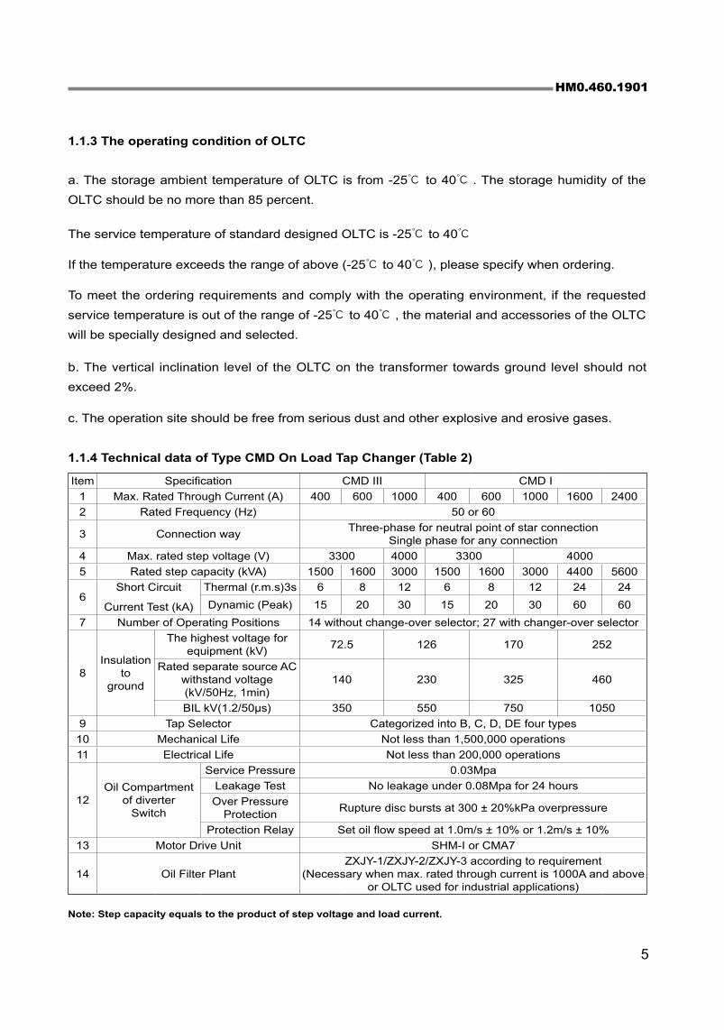
1.1.4 Technical data of Type CMD On Load Tap Changer (Table 2)
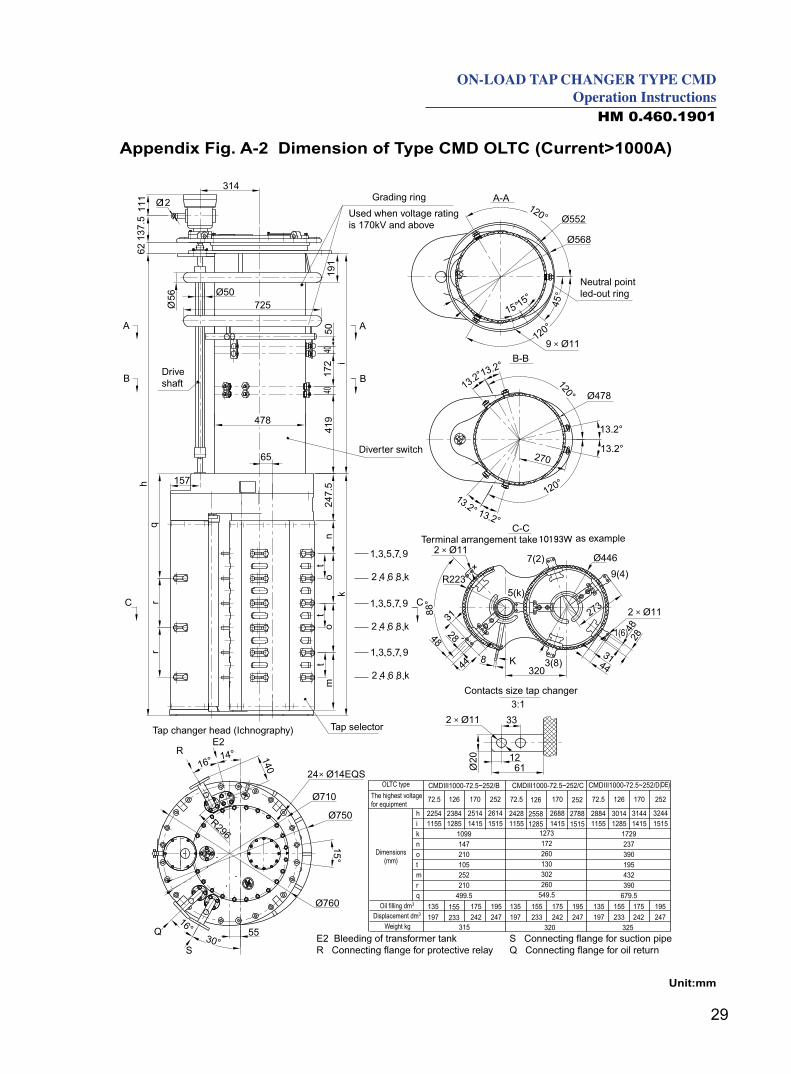
Item Specification CMD III CMD I
1 Max. Rated Through Current (A) 400 600 1000 400 600 1000 1600 2400
2 Rated Frequency (Hz) 50 or 60
3 Connection wayThree-phase for neutral point of star connection
Single phase for any connection
4 Max. rated step voltage (V) 3300 4000 3300 4000
5 Rated step capacity (kVA) 1500 1600 3000 1500 1600 3000 4400 5600
6Short Circuit
Current Test (kA)
Thermal (r.m.s)3s 6 8 12 6 8 12 24 24
Dynamic (Peak) 15 20 30 15 20 30 60 60
7 Number of Operating Positions 14 without change-over selector; 27 with changer-over selector
8Insulation
to ground
The highest voltage for equipment (kV)
72.5 126 170 252
Rated separate source AC withstand voltage(kV/50Hz, 1min)
140 230 325 460
BIL kV(1.2/50µs) 350 550 750 1050
9 Tap Selector Categorized into B, C, D, DE four types
10 Mechanical Life Not less than 1,500,000 operations
11 Electrical Life Not less than 200,000 operations
12Oil Compartment
of diverterSwitch
Service Pressure 0.03Mpa
Leakage Test No leakage under 0.08Mpa for 24 hours
Over Pressure Protection
Rupture disc bursts at 300 ± 20%kPa overpressure
Protection Relay Set oil flow speed at 1.0m/s ± 10% or 1.2m/s ± 10%
13 Motor Drive Unit SHM-I or CMA7
14 Oil Filter PlantZXJY-1/ZXJY-2/ZXJY-3 according to requirement
(Necessary when max. rated through current is 1000A and above or OLTC used for industrial applications)
Note: Step capacity equals to the product of step voltage and load current.
6
Fig 3. Tap selector basic connection diagram
steps
step
s
steps steps steps steps
steps
stepsstepsstepsstepssteps
steps
steps steps steps steps steps
stepsstepsstepsstepssteps
steps steps stepssteps
stepsstepsstepssteps
step
s
step
s
step
s
step
sst
eps
step
sst
eps
step
s
step
sst
eps
step
s
step
s
step
s
step
sst
eps
step
s
step
s
step
s
step
s
step
s
step
s
step
s
step
s
step
s
step
s
step
s
step
s
step
s
step
s
7
ON-LOAD TAP CHANGER TYPE CMDOperation Instructions
HM 0.460.1901
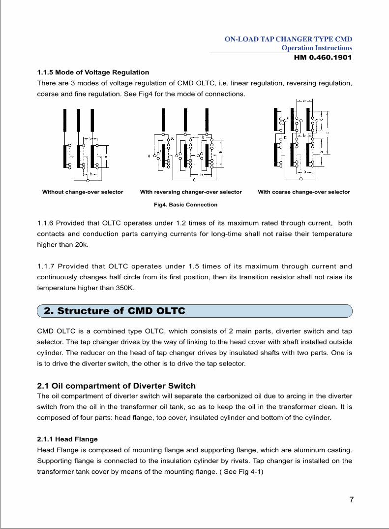
1.1.5 Mode of Voltage Regulation
There are 3 modes of voltage regulation of CMD OLTC, i.e. linear regulation, reversing regulation,
coarse and fine regulation. See Fig4 for the mode of connections.
Without change-over selector With coarse change-over selectorWith reversing changer-over selector
1.1.6 Provided that OLTC operates under 1.2 times of its maximum rated through current, both
contacts and conduction parts carrying currents for long-time shall not raise their temperature
higher than 20k.
1.1.7 Provided that OLTC operates under 1.5 times of its maximum through current and
continuously changes half circle from its first position, then its transition resistor shall not raise its
temperature higher than 350K.
2. Structure of CMD OLTC
CMD OLTC is a combined type OLTC, which consists of 2 main parts, diverter switch and tap
selector. The tap changer drives by the way of linking to the head cover with shaft installed outside
cylinder. The reducer on the head of tap changer drives by insulated shafts with two parts. One is
is to drive the diverter switch, the other is to drive the tap selector.
2.1 Oil compartment of Diverter SwitchThe oil compartment of diverter switch will separate the carbonized oil due to arcing in the diverter
switch from the oil in the transformer oil tank, so as to keep the oil in the transformer clean. It is
composed of four parts: head flange, top cover, insulated cylinder and bottom of the cylinder.
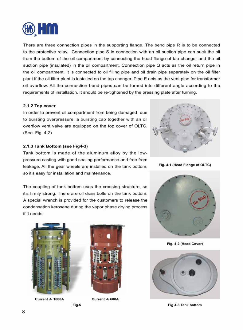
2.1.1 Head Flange
Head Flange is composed of mounting flange and supporting flange, which are aluminum casting.
Supporting flange is connected to the insulation cylinder by rivets. Tap changer is installed on the
transformer tank cover by means of the mounting flange. ( See Fig 4-1)
Fig4. Basic Connection
8
There are three connection pipes in the supporting flange. The bend pipe R is to be connected
to the protective relay. Connection pipe S in connection with an oil suction pipe can suck the oil
from the bottom of the oil compartment by connecting the head flange of tap changer and the oil
suction pipe (insulated) in the oil compartment. Connection pipe Q acts as the oil return pipe in
the oil compartment. It is connected to oil filling pipe and oil drain pipe separately on the oil filter
plant if the oil filter plant is installed on the tap changer. Pipe E acts as the vent pipe for transformer
oil overflow. All the connection bend pipes can be turned into different angle according to the
requirements of installation. It should be re-tightened by the pressing plate after turning.
2.1.2 Top cover
In order to prevent oil compartment from being damaged due
to bursting overpressure, a bursting cap together with an oil
overflow vent valve are equipped on the top cover of OLTC.
(See Fig. 4-2)
2.1.3 Tank Bottom (see Fig4-3)
Tank bottom is made of the aluminum alloy by the low-
pressure casting with good sealing performance and free from
leakage. All the gear wheels are installed on the tank bottom,
so it’s easy for installation and maintenance.
The coupling of tank bottom uses the crossing structure, so
it’s firmly strong. There are oil drain bolts on the tank bottom.
A special wrench is provided for the customers to release the
condensation kerosene during the vapor phase drying process
if it needs.
Current ≥ 1000A Current ≤ 600A
Fig.5 Fig 4-3 Tank bottom
Fig. 4-2 (Head Cover)
Fig. 4-1 (Head Flange of OLTC)
9
ON-LOAD TAP CHANGER TYPE CMDOperation Instructions
HM 0.460.1901
2.2 Diverter Switch Insert (See Fig. 5)Diverter switch insert has two kinds of structure according to different current. It adopts the parallel
connective contacts in several points, in order to have strong carrying capacity.
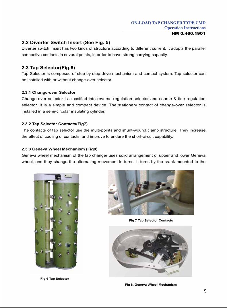
2.3 Tap Selector(Fig.6)Tap Selector is composed of step-by-step drive mechanism and contact system. Tap selector can
be installed with or without change-over selector.
2.3.1 Change-over Selector
Change-over selector is classified into reverse regulation selector and coarse & fine regulation
selector. It is a simple and compact device. The stationary contact of change-over selector is
installed in a semi-circular insulating cylinder.
2.3.2 Tap Selector Contacts(Fig7)
The contacts of tap selector use the multi-points and shunt-wound clamp structure. They increase
the effect of cooling of contacts; and improve to endure the short-circuit capability.
2.3.3 Geneva Wheel Mechanism (Fig8)
Geneva wheel mechanism of the tap changer uses solid arrangement of upper and lower Geneva
wheel, and they change the alternating movement in turns. It turns by the crank mounted to the
Fig 6 Tap Selector
Fig 7 Tap Selector Contacts
Fig 8. Geneva Wheel Mechanism
10
tank bottom of tap changer, then the Geneva wheel alternates in turns. It takes the movable
contact of tap selector to the pre-selected tapping position. Also, it has mechanism limit block parts
in Geneva wheel mechanism.
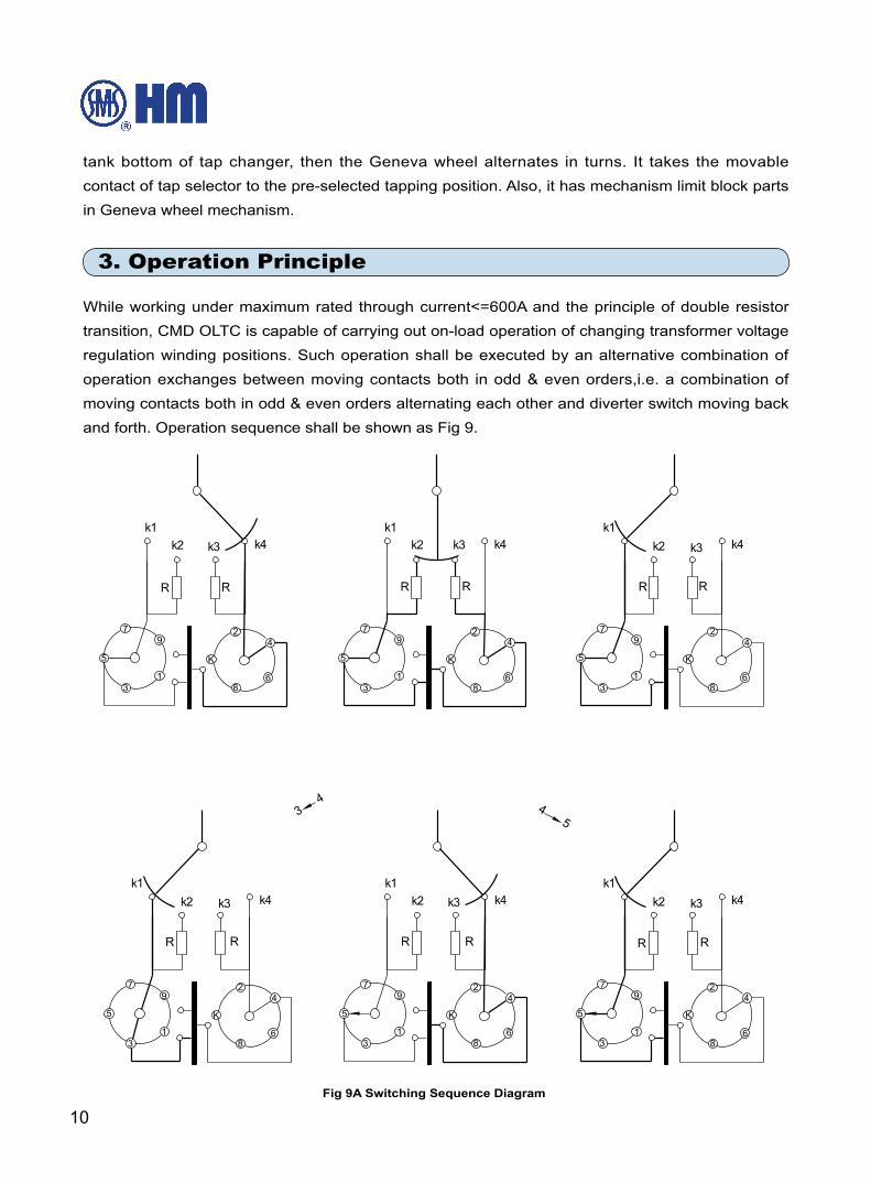
3. Operation Principle
While working under maximum rated through current<=600A and the principle of double resistor
transition, CMD OLTC is capable of carrying out on-load operation of changing transformer voltage
regulation winding positions. Such operation shall be executed by an alternative combination of
operation exchanges between moving contacts both in odd & even orders,i.e. a combination of
moving contacts both in odd & even orders alternating each other and diverter switch moving back
and forth. Operation sequence shall be shown as Fig 9.
Fig 9A Switching Sequence Diagram
11
ON-LOAD TAP CHANGER TYPE CMDOperation Instructions
HM 0.460.1901
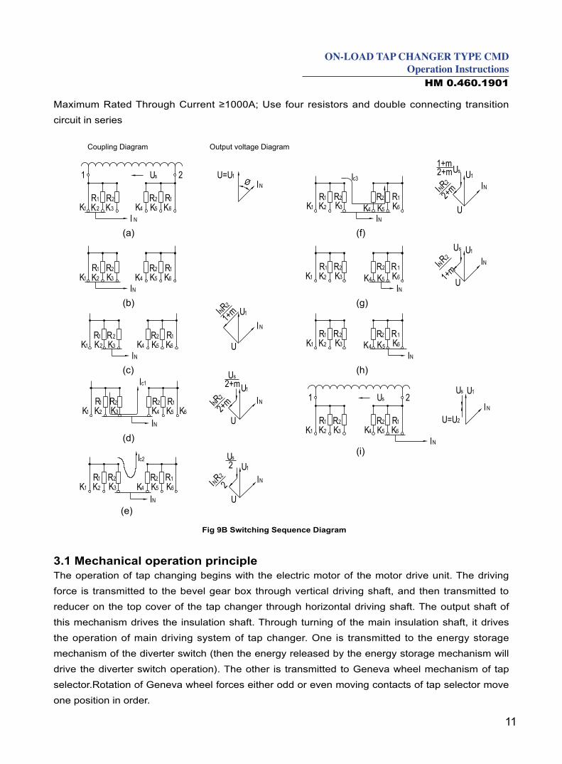
Maximum Rated Through Current ≥1000A; Use four resistors and double connecting transition
circuit in series
Output voltage DiagramCoupling Diagram
Fig 9B Switching Sequence Diagram
3.1 Mechanical operation principle The operation of tap changing begins with the electric motor of the motor drive unit. The driving
force is transmitted to the bevel gear box through vertical driving shaft, and then transmitted to
reducer on the top cover of the tap changer through horizontal driving shaft. The output shaft of
this mechanism drives the insulation shaft. Through turning of the main insulation shaft, it drives
the operation of main driving system of tap changer. One is transmitted to the energy storage
mechanism of the diverter switch (then the energy released by the energy storage mechanism will
drive the diverter switch operation). The other is transmitted to Geneva wheel mechanism of tap
selector.Rotation of Geneva wheel forces either odd or even moving contacts of tap selector move
one position in order.
12
4. Installation Method of CMD On Load Tap Changer (For Bell Type)
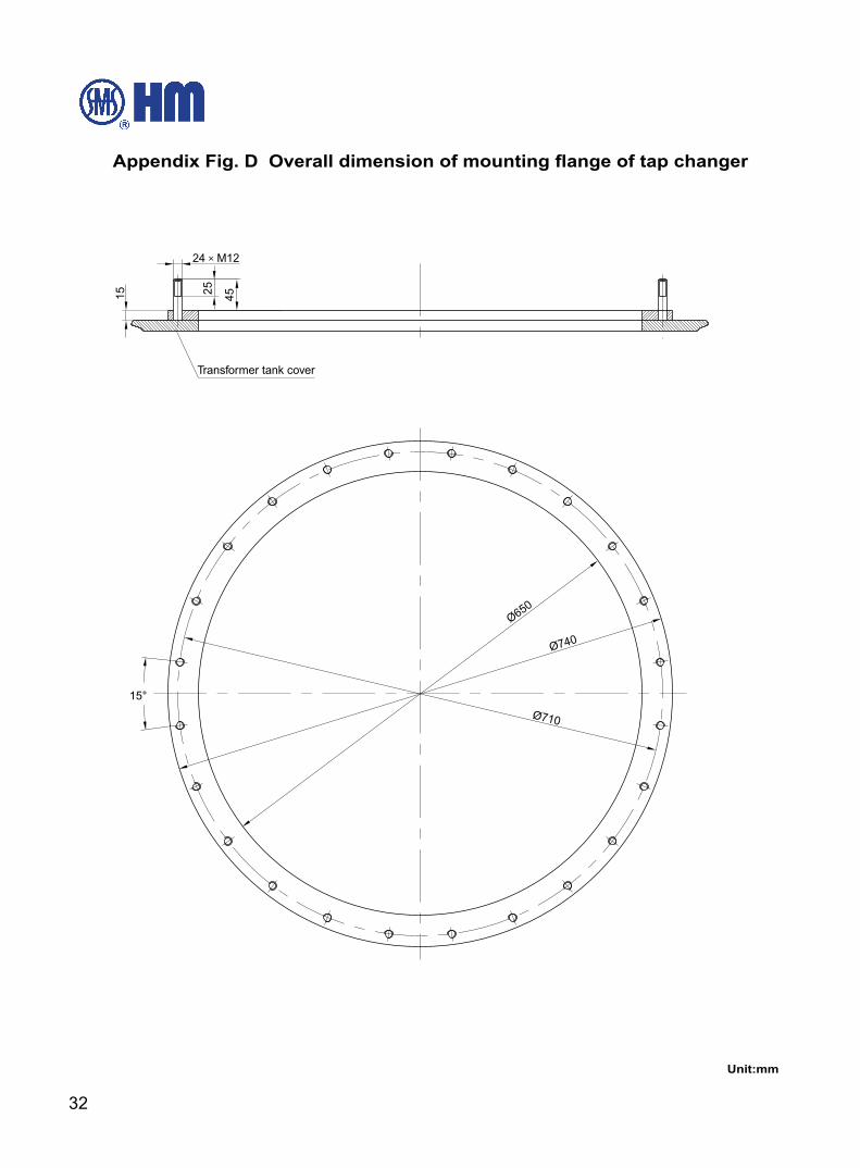
4.1 OLTC being installed on transformer's tank cover via mounting flange A mounting flange with Φ650mm inner diameter will be required on the tank cover together with
oil resistant sealing gasket (prepared by the user). Please see Appendix Fig. D. Studs will be used
with its one end threaded into the mounting flange. The stud should project at least 45mm above
the mounting flange.
4.2 Procedure of installing CMD OLTC on tank cover of Bell-type transformer is listed as follows:There is a demountable head flange for the installation of "Bell-type" OLTC, which is composed of
two parts, i.e. one is temporarily fixed to supporting flange of transformer's supporting frame where
insulation cylinder of oil compartment is to be installed, the other fixed to head flange of transformer
tank cover. Both flanges are connected by O-type ring and fasteners.
4.2.1 Remove mounting flange from head cover
a. Let off Fixing- Position plate from bevel gear box on the head of flange and put it on the flat side
of shaft and then fix it as shown as Fig 10 in order to prevent from shaft rotation in gear box as
consequences of installation position change of diverter switch insert.(Please restore the position
to its normal operation position after installation .)
b. Take off flange cover on the head of OLTC and Be cautious of its 0-type ring (sealing gasket) .
c. Remove M8 fixing nuts and washers that fasten the diverter switch insert unit.
d. Hoist up main body of OLTC out of transformer and leave it in a clean space. Note: No free
operation after taking out.
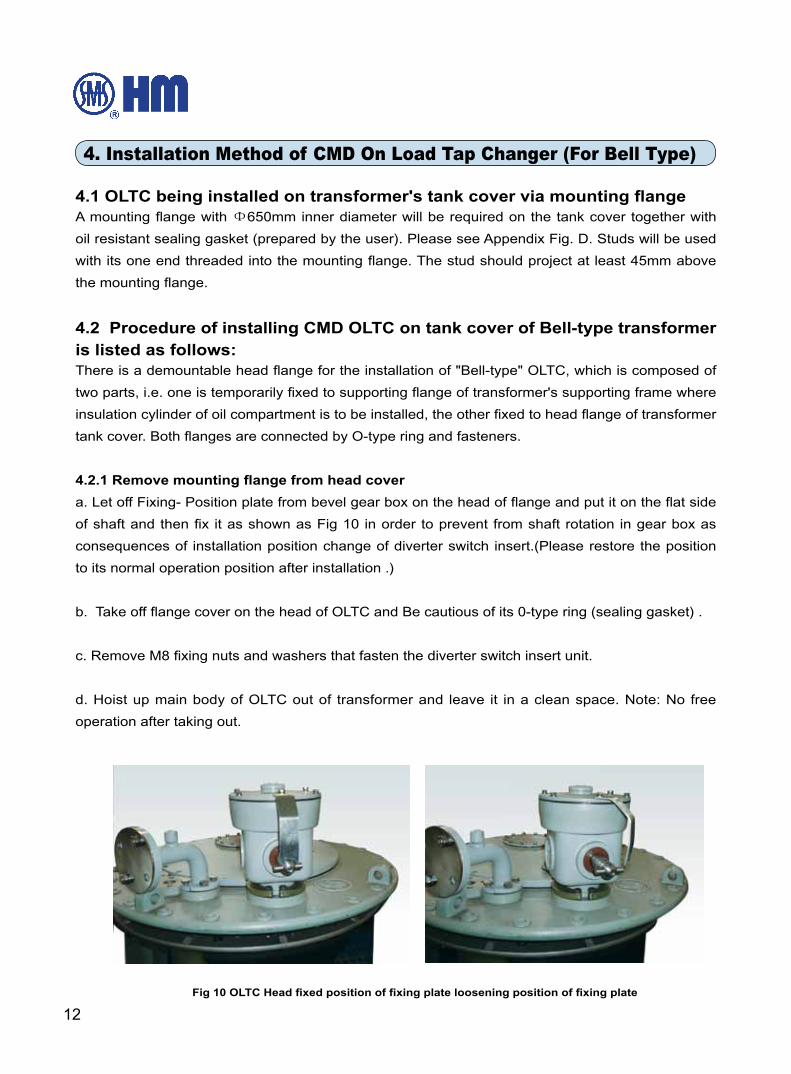
Fig 10 OLTC Head fixed position of fixing plate loosening position of fixing plate
13
ON-LOAD TAP CHANGER TYPE CMDOperation Instructions
HM 0.460.1901
e. Take off oil suction pipe and be cautious of o-type sealing gasket ring.
f. Unscrew the three M8 fixing nuts on the bevel gear box of the head cover. Lift the bevel gear box
out upwards.
g. Loosen the bolts between supporting flange and mounting flange, and pay more attention to
the triangle position mark between two flanges. Remove the mounting flange, and keep the o-ring
between two flanges properly.
4.2.2 In order to ensure correct procedure of installing OLTC, pre-installation is a must
a. Contra-position pre-installation of supporting flange and mounting flange
Fix an adjustable supporting structure on transformer yoke, lift up OLTC onto the supporting
structure and then install OLTC's supporting flange on the structure temporarily.
Pre-installe head flange on the mounting flange on the transformer tank cover, adjust OLTC and
its supporting structure's positions in order to ensure both head mounting flange and supporting
flange in a natural contra-position against each other, and the position of OLTC on the supporting
structure correct.
b. Adjust assembly space between supporting flange and head flange
To adjust supporting structure by raising or lowering down installation height of supporting flange
in order to ensure the assembly space within the limit of 20mm between supporting flange and
installation flange.
After confirming that the pre-installation of OLTC on transformer's supporting structure is correct,
transformer winding lead shall be connected with its responding selector terminal. Now pre-
installation shall be carried out once more after connection. If there is no tap-position change,
no deformation or impact caused by lead with inappropriate length, then both flanges as
abovementioned shall be contra-positioned against each other during the period of transformer
installation.
4.3 Connecting transformer voltage regulation winding lead with OLTC
4.3.1 Connection between lead and tap selector
Voltage regulation winding lead shall be connected with its responding selector terminal as shown
as connection diagram supplied on delivery. In the meantime, codes marked on connection
terminals on selector's insulation cylinder shall be in correspondence with codes on winding leads.
Each unit of OLTC provides M10 bolts for connecting tap selector and transformer lead. Voltage
14
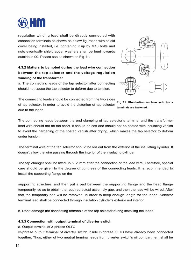
regulation winding lead shall be directly connected with
connection terminals as shown as below figuration with shield
cover being installed, i.e. tightening it up by M10 bolts and
nuts eventually shield cover washers shall be bent towards
outside in 90. Please see as shown as Fig 11.
4.3.2 Matters to be noted during the lead wire connection
between the tap selector and the voltage regulation
winding of the transformer
a. The connecting leads of the tap selector after connecting
should not cause the tap selector to deform due to tension.
The connecting leads should be connected from the two sides
of tap selector, in order to avoid the distortion of tap selector
due to the leads.
The connecting leads between the end clamping of tap selector’s terminal and the transformer
lead wire should not be too short. It should be soft and should not be coated with insulating vanish
to avoid the hardening of the coated vanish after drying, which makes the tap selector to deform
under tension.
The terminal wire of the tap selector should be led out from the exterior of the insulating cylinder. It
doesn’t allow the wire passing through the interior of the insulating cylinder.
The tap changer shall be lifted up 5~20mm after the connection of the lead wire. Therefore, special
care should be given to the degree of tightness of the connecting leads. It is recommended to
install the supporting flange on the
supporting structure, and then put a pad between the supporting flange and the head flange
temporarily, so as to obtain the required actual assembly gap, and then the lead will be wired. After
that the temporary pad will be removed, in order to keep enough length for the leads. Selector
terminal lead shall be connected through insulation cylinder's exterior not interior.
b. Don’t damage the connecting terminals of the tap selector during installing the leads.
4.3.3 Connection with output terminal of diverter switch
a. Output terminal of 3-phrase OLTC
I3-phrase output terminal of diverter switch inside 3-phrase OLTC have already been connected
together. Thus, either of two neutral terminal leads from diverter switch's oil compartment shall be
Fig 11. Illustration on how selector's
terminals are fastened.
15
ON-LOAD TAP CHANGER TYPE CMDOperation Instructions
HM 0.460.1901
optional and be directly clamped with 10 or 14 copper pole and be fastened with M10 bolts.
b. Output terminal of single-phrase OLTC
A single-phase tap changer is formed by parallel connection of the contacts of three-phase tap
changer. On the oil compartment of the diverter switch, there is a belt type conducting ring. The
leads of the take-off terminal of the tap changer are connected to the conducting ring. On this ring,
there are three Φ12.5 holes. Cheese head screws pass through these holes, and connect with the
leads and are locked by the shield cover together with the M10 nuts. After tightening up the nuts,
the lock washer of the shield cover is pried up 90°, thus stop the nuts from loosening.
4.4 Transformer Ratio TestBefore drying the transformer, a ratio test should be carried out with alternating voltage. To operate
the tap changer, insert a short pipe of Φ25mm nominal diameter into the horizontal shaft of bevel
gear box on the head flange of the tap changer, and fastened them with a M8 screw. A crank
handle is filled on the other end of the short pipe.
8.25 turns of the horizontal driving shaft are required for each tap changing operation. Because the
tap changer is not oil immersed, the number of tap changing should be reduced to a minimum.
After the ratio test, the tap changer must be returned to the default adjustment position. This
position can be determined from the adjustment position diagram supplied together with the tap
changer during delivery.
4.5 Drying and Oil Fill-in Generally the tap changer is dried together with the transformer; however, it can be dried
separately through the same drying process. The purpose of drying is to ensure the insulation level
of the tap changer. It should be follow the process below,
4.5.1 Vacuum drying
a. Drying in the oven room
During drying in the oven room, the tap changer’s top cover must be removed. Remove the
temporary plate on the suction pipe S and make sure to keep the oil pipe unobstructed.
The tap changer is put into the oven room with a temperature of about 60 ℃ , and heated in the
air under atmospheric pressure. The rate of temperature rise is 10℃ /h and the maximum heating
temperature is 110℃ .
Pre-drying: Drying process shall be done with ventilation and the highest temperature reaching for
110 for 10 hours.
16
b. Drying in the transformer oil tank
When the transformer is vacuum drying in its oil tank, the top cover of the tap changer is kept
tightly closed throughout the whole process. To ensure sufficient drying of the interior of the oil
compartment and the diverter switch insert, a by-pass pipe supplied by our factory (see appendix
drawing G) must be used to connect the oil filling flange on tap changer head to the overflow pipe
flange on the transformer oil tank (see appendix drawing B for the flange position).
It adopts the vacuum dryness under the remnant pressure putting on the tap changer in maximum
temperature 110℃ and no more than 10-3bar.
4.5.2 Vapor phase drying
When vapor phase drying is employed for drying the transformer and tap changer, the kerosene
drain plug at the bottom of the oil compartment should be opened to drain the kerosene condensate
from the oil compartment by special wrench. After the vapor phase drying, the kerosene drain plug
should be closed again.
a. Drying in the oven room
In the case of oven room drying, the top cover of the tap changer must be removed. Make sure to
keep the oil extraction pipe unobstructed.
Under the kerosene vapor temperature of 90 ℃ , the duration of heating is 3-4 hours. Raise the
temperature of kerosene vapor at a rate of 10℃ /h. Maximum temperature is 125℃ . The time for
drying basically depends upon the time required for transformer drying.
b. Drying in the transformer oil tank
If the transformer is vapor-phase dried in its tank, it should be lifted out the diverter switch insert.
After the vapor phase drying, check the kerosene drain plug at the bottom of the oil compartment to
make sure that it is tightly closed.
Matters to be noted after the drying process of the tap changer:
a. Do not operate the tap changer after drying without oil filling. If operation is required after drying,
the oil compartment of the diverter switch shall be fully filled with transformer oil and the tap
selector should be lubricated with transformer oil.
b. Check the tightness of fasteners. If any fastener is found out loosening, it must be retightened
and locked against looseness.
4.5.3 Oil Fill-in
Fasten up 24 M10 bolts and make sure that O-type sealing gasket ring be in right position When
17
ON-LOAD TAP CHANGER TYPE CMDOperation Instructions
HM 0.460.1901
OLTC's head cover is closed again.
The operation of filling oil in both transformer and OLTC shall be carried out only if both of them
are under vacuum circumstances. Fill sufficiently qualified oil in OLTC till it reaches the level of
transformer head cover horizontally. Thus, accessories such as bypass pipes supplied by our
factory shall be installed between OLTC's head oil fill-in flange and transformer's oil overflow flange
so as to pump both OLTC and transformer into vaccum state.
4.6 The installation of pipe connectionThe head flange of the tap changer is equipped with three bent pip. The orientation of these bent
pip can be determined as the requirements of installation. It can loosen the thrust collar of bent pip,
or bent pip freely.
4.6.1 Pipe connection of QJ4G-25 gas relay
QJ4G Buchholz relay (Gas relay) can be installed on the connection tube between the head of
the tap changer and the oil conservator, and it should be as close as possible to head of the tap
changer. Frequently it is connected directly to the flange of the bend pipe R. It must be installed
with the arrow of the gas relay pointing to the oil conservator.
4.6.2 Oil suction pipe connection
An oil suction pipe in the oil compartment reaches the bottom of oil compartment. It is connected
with oil suction pipe connection. It is used to extract the oil in the oil compartment of diverter switch
during maintenance or oil changing. Therefore, it should be taken out an oil suction pipe from a oil
suction pipe connection. The oil suction pipe goes through the lower part of oil compartment from
the sides of tap changer, and the length of oil suction pipe must be longer and lower the bottom of
the oil compartment. It is installed an oil drain valve in the lower end of the pipe.
This oil suction pipe may also be used as the oil discharge pipe with an oil filter plant.
4.6.3 Outlet of Oil fill-in Bent Pipes
This connection can be regarded as oil return pipe for oil filter plant and sealed with a dummy plug
if there is no oil filter plant. It is suggested to use an outlet pipe, of which one end is fixed with an
oil release valve, so that oil circulation filter be carried out through both oil suction pipes and oil fill-
in pipes in oil filter plant.
4.7 Installation of Motor Drive UnitAs OLTC's position control and driving device in the operation of tap position change, motor drive
unit can be operated either electrically or manually.
18
Matters to be noted during the installation of motor drive unit, as follows,
4.7.1 The motor drive unit must be connected to the adjustable position of tap changer, which is
indicated in the tap changer connection diagram supplied with the equipment.
4.7.2 Motor drive unit shall be installed vertically on transformer tank wall without inclination.
Attention: The mounting plate of the motor drive unit should be flat, otherwise the motor drive unit
will be deformed by twisting, or it will affect the tank sealing.
For the actual installation of the motor drive unit, see the operation instruction of Type SHM-1
motor drive unit.
4.8 Installation of bevel gear boxThe overall and mounting dimension of the bevel gear box, see appendix diagram C.
4.8.1 The bevel gear box is to be installed to a supporting structure on the transformer cover by 2
pieces of M16 bolts.
4.8.2 Driving Shaft (square shaft)
a. Installation of horizontal driving shaft
Rotate head gear box by loosening its thrust collar(6 M8 bolts) in order to keep its horizontal driving
shaft aiming at its bevel gear box's counterpart.
Install the horizontal driving shaft and tighten the fixing plate of bevel gear box.
b. Installation of vertical driving shaft
According to the dimension between the bevel gear and the vertical driving shaft of the motor drive
unit, minus 9mm and determine and machine the actual size of the vertical driving shaft. After
taking account of the expansion and contraction, certain gap (a total of gap about 2mm) should be
reserved for the connection of vertical driving shafts.
Install the vertical driving shaft; the locking plate in the clamping brackets near the motor drive unit
can only be turned up after checking the connection between the motor drive unit and tap changer.
If it has any difficulty to install the vertical driving shaft, an universal joint can be installed on the
driving shaft of bevel gear box.
The length of the vertical driving shaft may exceed 2 meters. In order to avoid swaying we
recommend installing a middle gear as a support for the vertical shaft. This can be specially
supplied if requested during ordering.
19
ON-LOAD TAP CHANGER TYPE CMDOperation Instructions
HM 0.460.1901
4.9 Verification of the connection of the tap changer and motor drive unitAfter connecting the tap changer with the motor drive unit, the mechanism should first be manually
operated for a complete cycle and make sure the indication of the position must be identical
between the motor drive unit and that tap changer before any operation by motor drive unit.
When the tap changer has been connected to the motor drive unit, the interval(or time interval)
between the instant of switching of the diverter switch and the ending of operation of the motor
drive unit should be the same in both direction of rotation.
In order to make sure the reliability of operation of tap changer, if vertical or horizontal shaft is
disconnected from the tap changer, test has to be taken after re-connection.
The verification of connection is carried out according to the following procedure:
4.9.1 Rotate the handle in the 1 → N direction. After the diverter switch has operated (start when
the sound of switch is heard), turn the handle continuously and record the number of turns until
a centre mark within grey area on the indicating wheel of the motor drive unit appears the same
position with the arrow. Record the number of turns as m.
4.9.2 Rotate the handle in the reverse direction N → 1 to return to its adjustment position. Record
the number of turns K in the same way as mentioned above.
4.9.3 The connection will be correct if m=K. If m ≠ K and m-K>1, then turn the handle 1/2 (m-k)
turns in the direction of increment of turns, and finally connect the vertical driving shaft to the motor
drive unit.
4.9.4 Check the different of turns between the motor drive unit and the tap changer in the same
way as mentioned above, until the same number of turns for the two direction of switching
operations.
For example:
The verification of connection of Type CMD tap changer and Type SHM-I motor drive unit: Turn
from position 10 (adjustment position) to position 11, m=5 turns. Turn backward from position 11
to position 10 (the original adjustment position), k=3 turns. The difference of turns of the handle
m-k=5-3=2 turns.
Turn to be adjusted 1/2 (m-k) = 1/2 (5-3) = 1 turn.
Loosen the connection between the vertical driving shaft and the motor drive unit. Turn the handle
in the direction 10 → 11 for one turn. Then again make connections.
20
Check that the difference of turns in both directions has been balanced.
a. Record number of turns m an k
b. Turn 1/2 (m-k) turns in the direction in the increment of turns during loosening of connection
c. Again make connection and verify until m-k<1.
4.10 Operational test of the tap changer
4.10.1 Mechanical operational test
Before the test of transformer with electricity, 5 complete cycles of mechanical operating test (no
less than 200 operations) must be performed. There should be no damage to the tap changer
and motor drive unit. The position indication of the motor drive unit, its position indication of the
controller and the position indication of the tap changer should be the same. Both the mechanical
and electrical limit protection should be reliable.
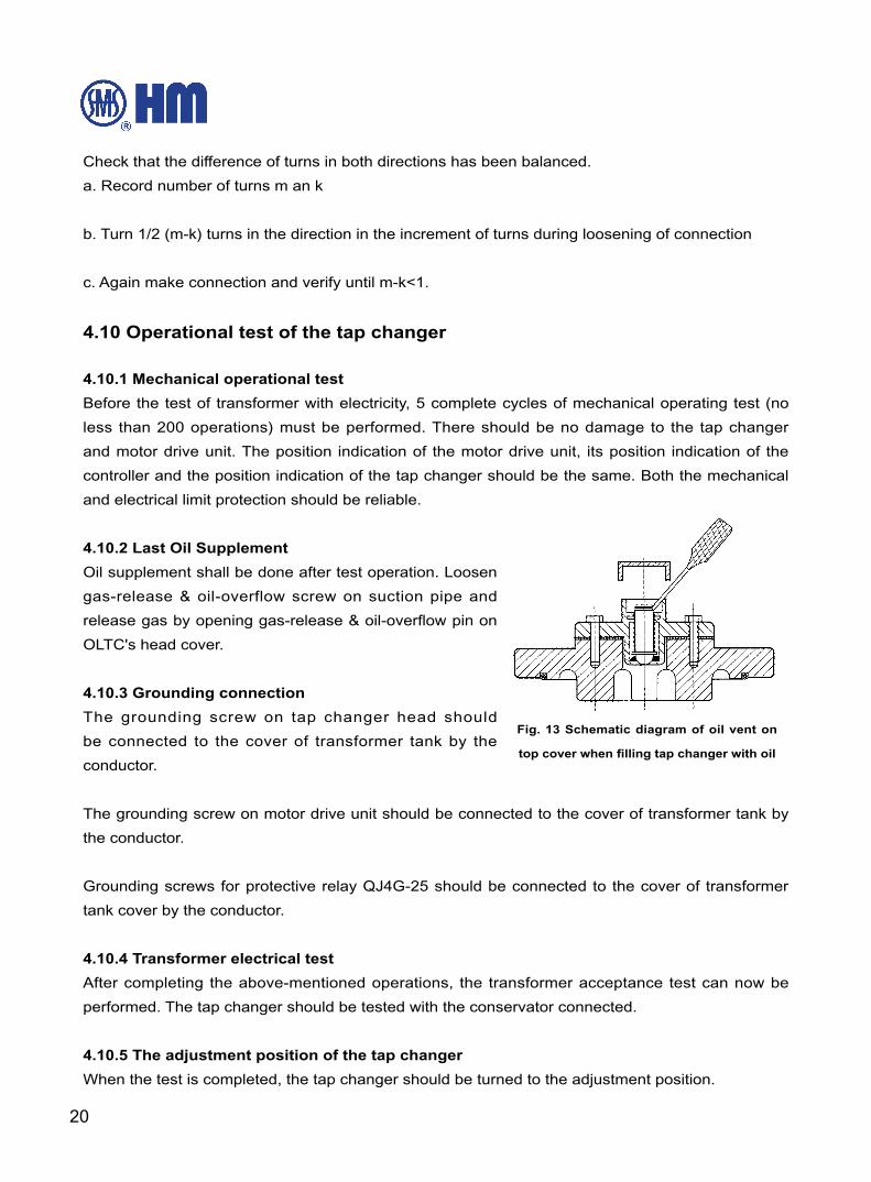
4.10.2 Last Oil Supplement
Oil supplement shall be done after test operation. Loosen
gas-release & oil-overflow screw on suction pipe and
release gas by opening gas-release & oil-overflow pin on
OLTC's head cover.
4.10.3 Grounding connection
The grounding screw on tap changer head should
be connected to the cover of transformer tank by the
conductor.
The grounding screw on motor drive unit should be connected to the cover of transformer tank by
the conductor.
Grounding screws for protective relay QJ4G-25 should be connected to the cover of transformer
tank cover by the conductor.
4.10.4 Transformer electrical test
After completing the above-mentioned operations, the transformer acceptance test can now be
performed. The tap changer should be tested with the conservator connected.
4.10.5 The adjustment position of the tap changer
When the test is completed, the tap changer should be turned to the adjustment position.
Fig. 13 Schematic diagram of oil vent on
top cover when filling tap changer with oil
21
ON-LOAD TAP CHANGER TYPE CMDOperation Instructions
HM 0.460.1901
4.11 Transportation of Transformer & OLTC togetherMake sure the safety of transportation (such as adding up an additional supporting structure
temporarily) before assembly of OLTC and transformer. It is unnecessary to dismantle OLTC due
to its "immersed" structure. Provided that dismantlement is unavoidable due to transportation
problems, the connection between vertical driving shaft & motor drive unit shall be let off so that
motor driving unit can be transported on horizontal level. Installation of motor driving unit after
arrival can be restored as stated as abovementioned.
If the transformer is transported or stored without the conservator, then the bypass pipe (see the
appendix drawing F) supplied as a spare part can be installed between the oil filling flange of the
tap changer and the overflow pipe flange of the transformer.
When transformer is under transportation or storage without oil being filled-in, then oil in diverter
switch's compartment shall be dispelled from completely. In the meantime, bypass pipe must be
installed so that both diverter switch's compartment and transformer's oil tank be borne with same
pressure. (nitrogen sealing)
In order to avoid damaging the tap changer caused by the shifting of moving parts, they must be
temporarily secured.
Note: Bypass pipes must be dismantled before transformer is installed and put into
operation on site.
4.12 Put into operation on siteBefore putting into operation of the transformer, the operating test of the tap changer and motor
drive unit must be done according to section 4.9. In the same time, check the proper function of the
Buchholz relay.
The Buchholz relay should be connected to the tripping circuit of the line circuit breaker, in case
the Buchholz relay is energized, it will instantly cut off the transformer circuit. “Transformer Off’ test
button on the top of the Buchholz relay can be used to test the function of the line circuit breaker.
Check whether all the valves between the oil conservator and the tap changer open or not, then put
the tap changer into operation. In the meantime, exchange gas accumulated under OLTC's head
cover may cause certain amount of oil outlet. Make sure everything is ok with OLTC before putting
it into operation.
5. Operation Supervision
Periodically examining oil pollution level in oil compartment of diverter switch is an effective
22
measure of monitoring OLTC's operation.
5.1 For periodic examination of the oil in the insulating cylinder of the diverter switch, we
recommend carrying out oil sampling test after one-year operations under rated current to ascertain
that the dielectric strength is not less than 30kV, the water content is not over 40PPm. For single
phase OLTC, the dielectric strength is not less than 40kV, the water content is not more than
30PPm.
5.2 Frequent operation of OLTC causes an impact on contact's endurance. Thus, "Overcurrent self-
locking device" shall be installed for automatically stopping operation provided that onload current
exceeds 2 times of max.rated through current.
5.3 the tripping contact of the QJ4G-25 protective relay is set to operate at an oil speed of 1.0m/
s ±10% or 1.2m/s ± 10%. This contact should be connected the tripping circuit of the transformer
circuit breaker. In case a failure occurs within the on load tap changer, then large amount of gas will
generate, causing a rush of oil flow to move the relay flapper, which breaks the tripping contacts,
it must cut off the electricity of the transformer to avoid overspreading of the damage. Once the
protective relay relay operated, don’t re-energize the transformer before the inspection by lifting the
diverter switch insert.
5.4 An rupture disk is installed on the top cover of the tap changer which should not be damaged
during normal tap changing operation of the diverter switch. Only when a failure is generated
within the diverter switch, then the disk bursts when the pressure in the oil compartment exceeds
30±20%KPa, thus it functions as an overpressure protection to avoid overspreading of the damage.
During the installation and maintenance of on load tap changer, please pay more attention that
don’t step on or put heavy things on the pressure cover.
6. Whole Set Supply Range
6.1 Range of a whole set of OLTC Supplya. Tap changer unit
b. Buchholz relay
c. Driving shaft and bevel gear box
d. Motor Drive Unit
e. Accessories
23
ON-LOAD TAP CHANGER TYPE CMDOperation Instructions
HM 0.460.1901
Check the contents according to the packing list. Place the tap changer equipment in a well-
ventilated warehouse with relative humidity of less than 85% and temperature between -25℃ and
+40℃ . There should be no corrosive gas and it will not affect by the rain or snow.
7. Maintenance and Repair
7.1 Periodical MaintenanceThe transformer oil in the oil compartment of diverter switch will become carbonized after many
times of switching, so it is recommended that periodic oil sampling should be done according to
Section 5.1 for laboratory test. The oil shall be replaced when its dielectric strength is less than
30kV and the water content is over 40PPm.
During the oil changing, the dirty oil is completely extracted from the oil compartment, then the
insulating cylinder and the diverter switch are flushed with clean oil. This oil is again completely
extracted. Finally fill with clean oil again.
If the tap changing operation exceeds 15,000 operations annually, it is recommended to install a
fixed oil filter plant to the tap changer.
The oil conservator and the breather for this on load tap changer are maintained usually the same
as those of the transformer.
7.2 Periodical Inspection & Repair During the period of long-time operation, only diverter switch need be periodically inspected and/or
repaired. Please refer to Timetable of Inspection & Repair for details.
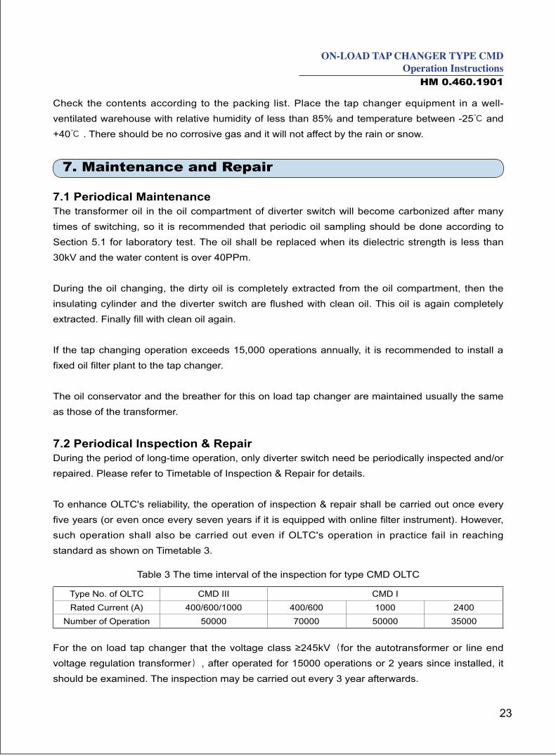
To enhance OLTC's reliability, the operation of inspection & repair shall be carried out once every
five years (or even once every seven years if it is equipped with online filter instrument). However,
such operation shall also be carried out even if OLTC's operation in practice fail in reaching
standard as shown on Timetable 3.
Type No. of OLTC CMD III CMD I
Rated Current (A) 400/600/1000 400/600 1000 2400
Number of Operation 50000 70000 50000 35000
Table 3 The time interval of the inspection for type CMD OLTC
For the on load tap changer that the voltage class ≥245kV(for the autotransformer or line end
voltage regulation transformer), after operated for 15000 operations or 2 years since installed, it
should be examined. The inspection may be carried out every 3 year afterwards.
24
The inspection items include lifting out the diverter switch insert, cleaning the entire switch and
insulating cylinder properly, measuring contact erosion, checking and re-tightening all the insulator
and energy storage mechanism. Small capacity lifting equipment may be used to lift out the diverter
switch insert. During the repair, the time of air exposure of diverter switch insert shall not exceed 10
hours or it shall be dried as specified in section 4.5.
7.3 Diverter Switch Insert Take-outAll the terminals (primary and secondary) shall be grounded after the transformer is disconnected
from the networks. The diverter switch insert can be drawn out at any operating position. However,
we recommend that the diverter switch insert be drawn out at its adjustment position. (See
Appendix Working Position's Layout ).
7.3.1 Close all the valves on the oil conservator, transformer oil tank and the head of tap changer.
7.3.2 Open the valve on the oil draining pipe. Lower the oil level of the tap changer head until it is
flush with the surface of the transformer tank cover. Loosen the gas vent and oil overflow screw.
7.3.3 Loosen the connection bolts of the head cover. Remove the cover; Be Cautious of sealing
gasket.
7.3.4 Dismantle the bolt and washer of tightening diverter switch insert.
7.3.5 Carefully lift up the diverter switch insert; And do not touch oil suction pipe.
7.4 Cleaning
7.4.1 Cleaning oil compartment of diverter switch
Thoroughly drained the dirty oil from the oil compartment of diverter switch and flush it with
qualified transformer oil. If necessary, brush away the carbon deposits stuck to the inner wall of the
insulating cylinder. Then again flush it with new oil, drain away all the dirty oil. After cleaning, tightly
close the top cover of the diverter switch.
7.4.2 After taking out diverter switch insert, it can be washed with qualified transformer oil and be
brushed if necessary.
7.5 Preliminary examination of the diverter switch insert
7.5.1 Check whether all the fasteners and screws are loosen or not.
25
ON-LOAD TAP CHANGER TYPE CMDOperation Instructions
HM 0.460.1901
7.5.2 Check whether the main spring, reset spring and jaw plate of the energy storage mechanism
are deformed or broken. Check the damping device of the energy storage mechanism.
7.5.3 Check whether the braided wire connection of each contact is damaged or not.
7.5.4 Inspect moving contacts & stationary contacts' burning and/or damage degree.
7.5.5 Check whether the flat wire of the transition resistor break or not. Measure and compare the
value of transition resistor and the value on the nameplate (The resistor value should be measured
at the open side of the transition contact.). It shall be within the tolerance of ±10% rated value.
7.5.6 Measure the contact resistance of the odd and even number contacts of each phase to the
output terminal.
7.5.7 Mensurate the switching sequence of movable contact (for double-resistor transition diverter
switch, electric current≤600A)
If the burning is over 3mm for any contact in arcing contact of diverter switch, it must replace the all
arc contact.
1.Check the braided contact lead connecting with main and arc contact and transition contact.
2.Check whether M6 x 18 bolts connecting with main and arc contact loosen or not.
After 100,000 operations of the tap changer, all braided contact lead have to be replaced even they
are not damaged.
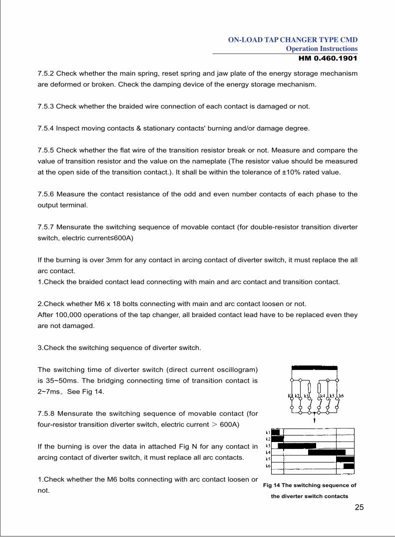
3.Check the switching sequence of diverter switch.
The switching time of diverter switch (direct current oscillogram)
is 35~50ms. The bridging connecting time of transition contact is
2~7ms。See Fig 14.
7.5.8 Mensurate the switching sequence of movable contact (for
four-resistor transition diverter switch, electric current > 600A)
If the burning is over the data in attached Fig N for any contact in
arcing contact of diverter switch, it must replace all arc contacts.
1.Check whether the M6 bolts connecting with arc contact loosen or
not.Fig 14 The switching sequence of
the diverter switch contacts
26
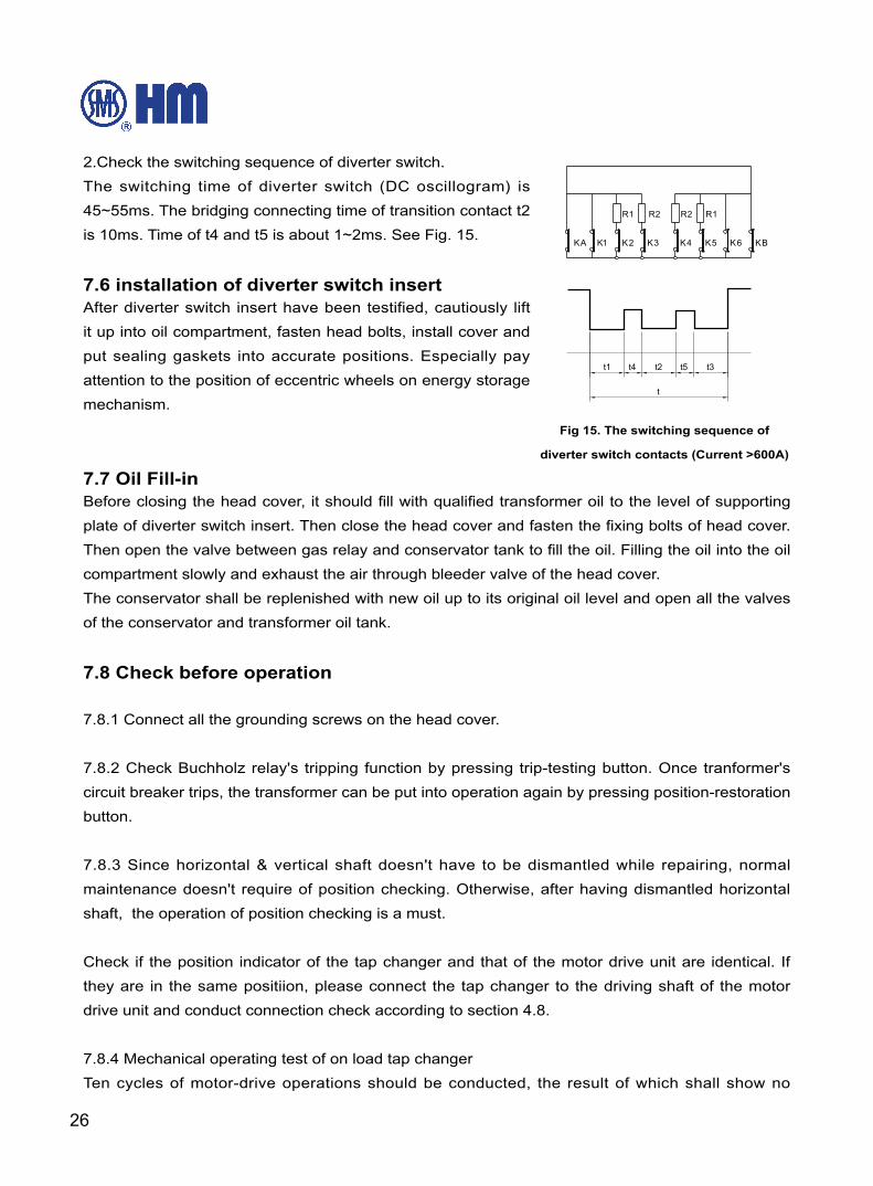
2.Check the switching sequence of diverter switch.
The switching time of diverter switch (DC oscillogram) is
45~55ms. The bridging connecting time of transition contact t2
is 10ms. Time of t4 and t5 is about 1~2ms. See Fig. 15.
7.6 installation of diverter switch insertAfter diverter switch insert have been testified, cautiously lift
it up into oil compartment, fasten head bolts, install cover and
put sealing gaskets into accurate positions. Especially pay
attention to the position of eccentric wheels on energy storage
mechanism.
7.7 Oil Fill-inBefore closing the head cover, it should fill with qualified transformer oil to the level of supporting
plate of diverter switch insert. Then close the head cover and fasten the fixing bolts of head cover.
Then open the valve between gas relay and conservator tank to fill the oil. Filling the oil into the oil
compartment slowly and exhaust the air through bleeder valve of the head cover.
The conservator shall be replenished with new oil up to its original oil level and open all the valves
of the conservator and transformer oil tank.
7.8 Check before operation
7.8.1 Connect all the grounding screws on the head cover.
7.8.2 Check Buchholz relay's tripping function by pressing trip-testing button. Once tranformer's
circuit breaker trips, the transformer can be put into operation again by pressing position-restoration
button.
7.8.3 Since horizontal & vertical shaft doesn't have to be dismantled while repairing, normal
maintenance doesn't require of position checking. Otherwise, after having dismantled horizontal
shaft, the operation of position checking is a must.
Check if the position indicator of the tap changer and that of the motor drive unit are identical. If
they are in the same positiion, please connect the tap changer to the driving shaft of the motor
drive unit and conduct connection check according to section 4.8.
7.8.4 Mechanical operating test of on load tap changer
Ten cycles of motor-drive operations should be conducted, the result of which shall show no
Fig 15. The switching sequence of
diverter switch contacts (Current >600A)
27
ON-LOAD TAP CHANGER TYPE CMDOperation Instructions
HM 0.460.1901
malfunctioning.
After having verified all the inspection, OLTC can be put into normal operation ever since then.
The inspection of the tap selector will only be performed along with the overhaul of the transformer.
No separate inspection is required.
8. Appendix
Dimension of Type CMD OLTC (Appendix Fig. A-1)……………………………………………………28
Dimension of Type CMD OLTC (Appendix Fig. A-2) …………………………………………………29
Connection diagram and operating position for Type CMD OLTC (Appendix Fig. B)…………………30
Overall dimension of mounting flange of Type CMD OLTC for bell type transformer
(Appendix Fig. C)…………………………………………………………………………………………31
Overall dimension of mounting flange of tap changer (Appendix Fig. D) ……………………………32
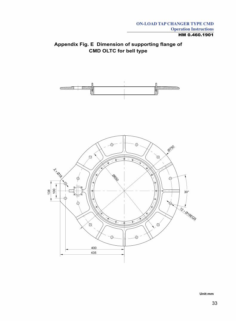
Dimension of supporting flange of CMD OLTC for bell type (Appendix Fig. E) ……………………33
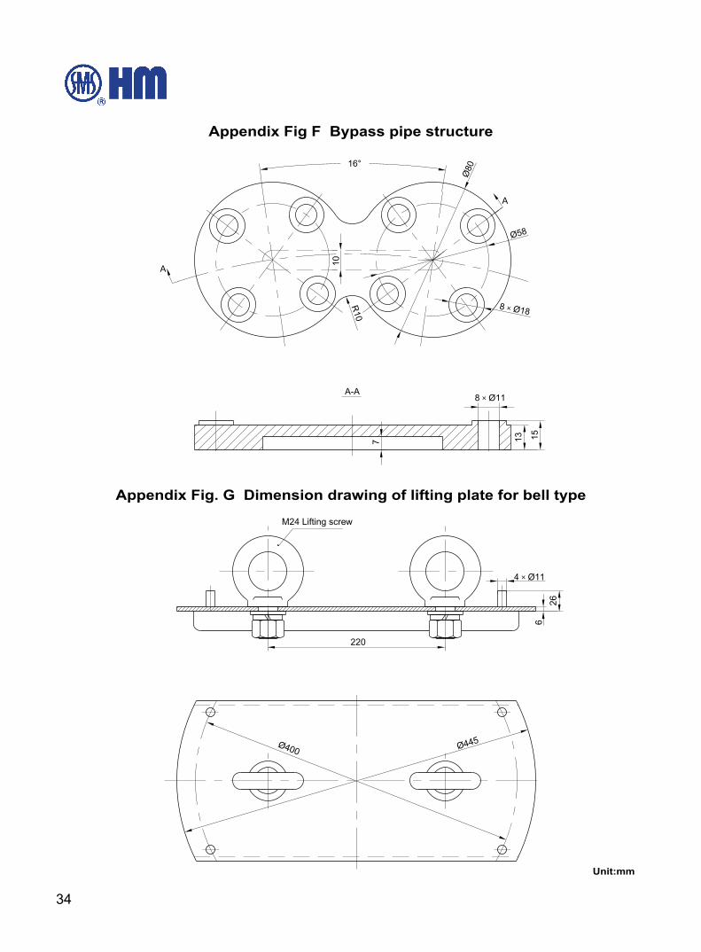
Bypass pipe structure (Appendix Fig F)…………………………………………………………………34
Dimension drawing of parallel connection piece for bell type (Appendix Fig. G) ……………………34
Overall mounting schematic drawing of horizontal and vertical bevel gear box
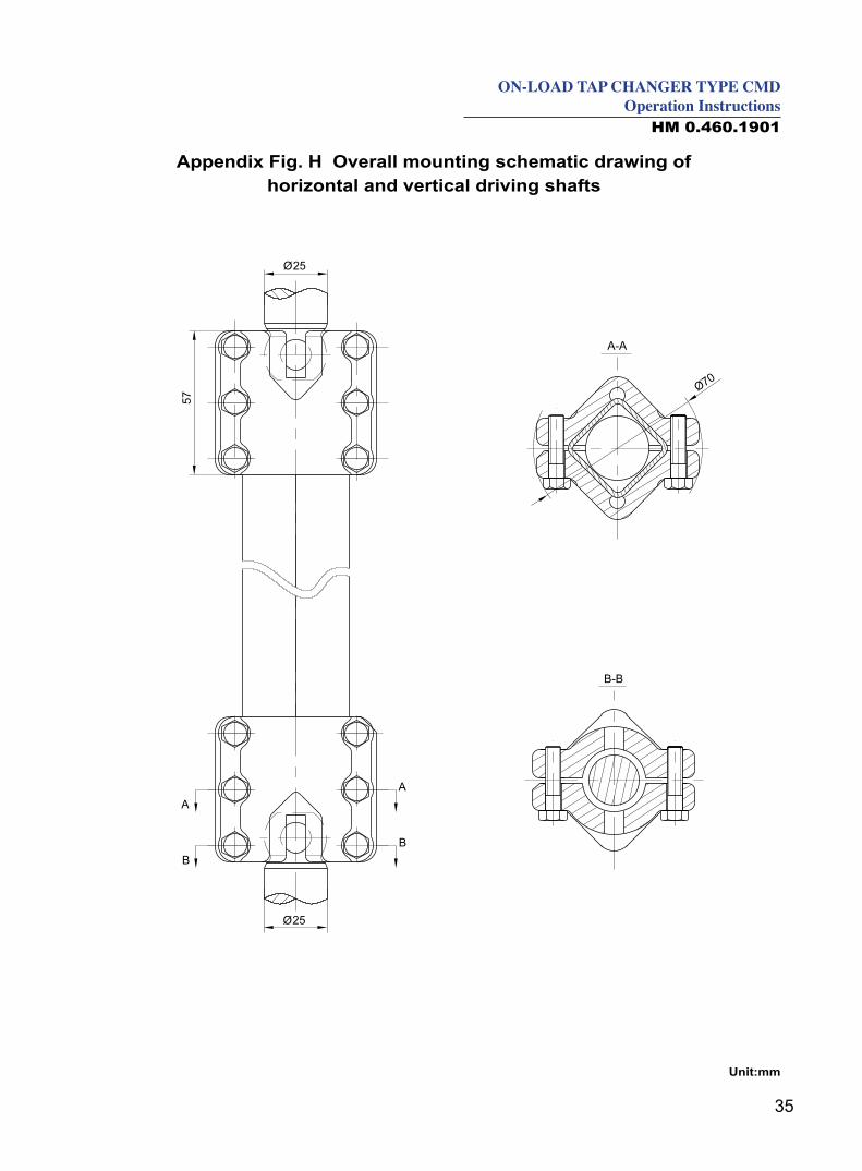
(Appendix Fig. H) …………………………………………………………………………………………35
Socket wrench for kerosene draining valve on the tank bottom of CMD Tap Changer
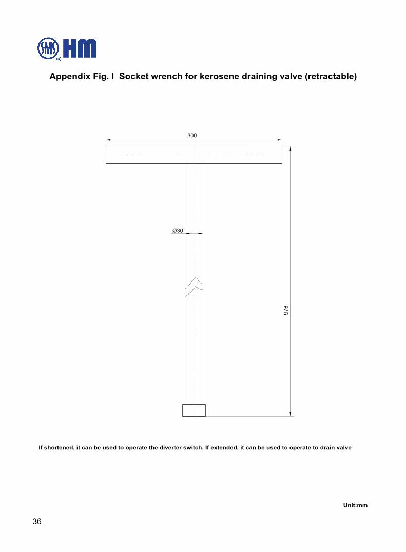
(Appendix Fig. I)……………………………………………………………………………………………36
Dimension of Bevel Gear Box (Appendix Fig. J) ………………………………………………………37
Overall dimension of Type SHM-III motor drive unit (Appendix Fig. K) ………………………………38
Connection and dimension drawing of type HMK-8 controller and SHM-III motor drive unit
(Appendix Fig. L) …………………………………………………………………………………………39
Drawing of contact Abrasion Measuring , (Appendix Fig. M) …………………………………………40
28
Unit:mm
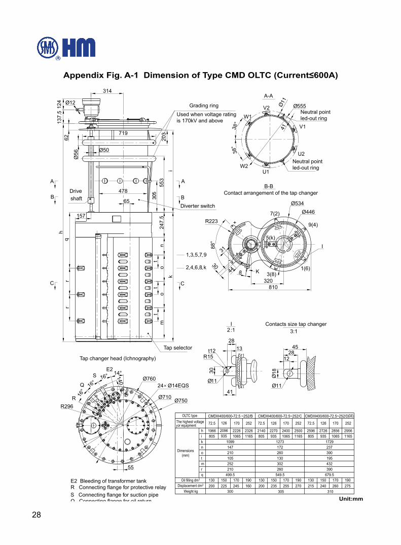
Appendix Fig. A-1 Dimension of Type CMD OLTC (Current≤600A)
41Ø11
305 Contact arrangement of the tap changer
Contacts size tap changer
29
ON-LOAD TAP CHANGER TYPE CMDOperation Instructions
HM 0.460.1901
10193W
44 4431
31
Contacts size tap changer
Unit:mm
Appendix Fig. A-2 Dimension of Type CMD OLTC (Current>1000A)
30
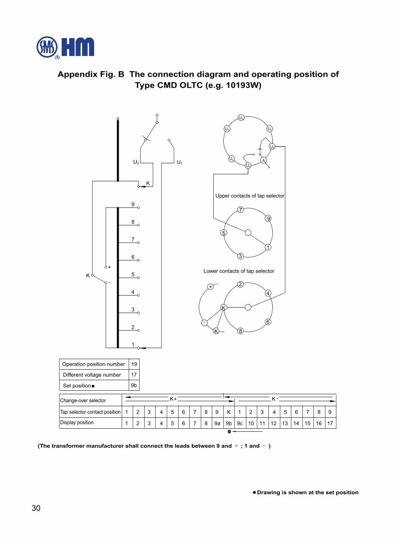
Appendix Fig. B The connection diagram and operating position of Type CMD OLTC (e.g. 10193W)
(The transformer manufacturer shall connect the leads between 9 and + ; 1 and - )
Drawing is shown at the set position
31
ON-LOAD TAP CHANGER TYPE CMDOperation Instructions
HM 0.460.1901
Mounting flange on the head
Supporting flange
K direction
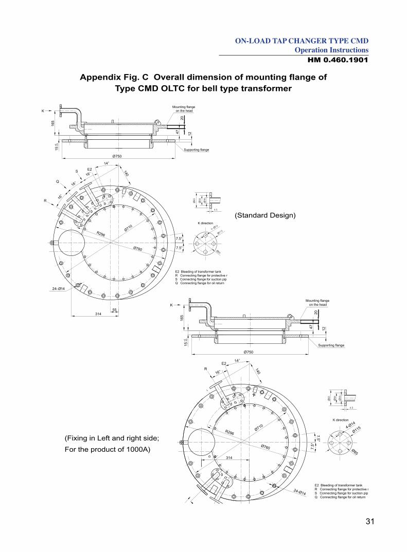
Appendix Fig. C Overall dimension of mounting flange of Type CMD OLTC for bell type transformer
Mounting flange on the head
Supporting flange
K direction
(Standard Design)
(Fixing in Left and right side;
For the product of 1000A)
32
Unit:mm
Appendix Fig. D Overall dimension of mounting flange of tap changer
33
ON-LOAD TAP CHANGER TYPE CMDOperation Instructions
HM 0.460.1901
Unit:mm
Appendix Fig. E Dimension of supporting flange ofCMD OLTC for bell type
34
Unit:mm
Appendix Fig F Bypass pipe structure
Appendix Fig. G Dimension drawing of lifting plate for bell type
35
ON-LOAD TAP CHANGER TYPE CMDOperation Instructions
HM 0.460.1901
Unit:mm
Appendix Fig. H Overall mounting schematic drawing of horizontal and vertical driving shafts
36
Unit:mm
Appendix Fig. I Socket wrench for kerosene draining valve (retractable)
If shortened, it can be used to operate the diverter switch. If extended, it can be used to operate to drain valve

37
ON-LOAD TAP CHANGER TYPE CMDOperation Instructions
HM 0.460.1901
Unit:mm
Appendix Fig. J Dimension of Bevel Gear Box
38
Unit:mm
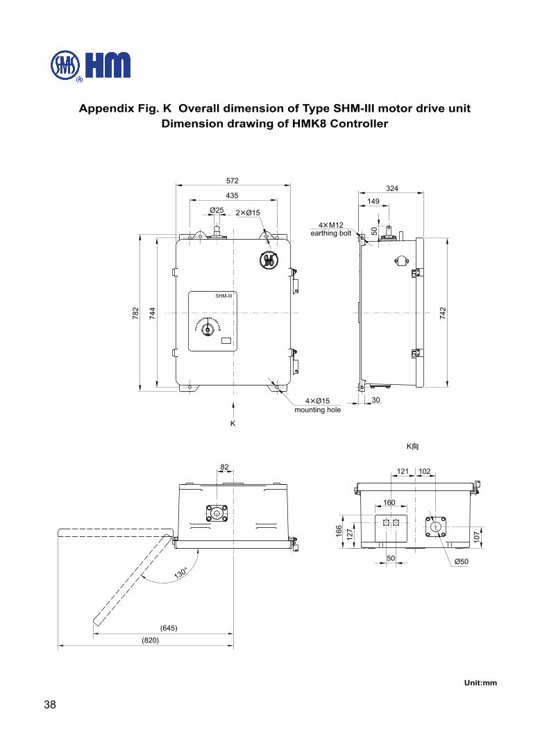
Appendix Fig. K Overall dimension of Type SHM-III motor drive unitDimension drawing of HMK8 Controller
39
ON-LOAD TAP CHANGER TYPE CMDOperation Instructions
HM 0.460.1901
Appendix Fig .L
Schematic Drawing of outside connecting leads for SHM motor drive unit and HMK8 Controller
X1 socket No. DesignationX1-1 L1X1-2 L2X1-3 L3X1-4 L2X1-5 NX1-6 N
X3 socket No. DesignationX3-1 Tap position signal No. “1”X3-2 Tap position signal No. “2”X3-3 Tap position signal No. “3”X3-4 Tap position signal No. “4”X3-5 Tap position signal No. “5”X3-6 Tap position signal No. “6”X3-7 Tap position signal No. “7”…. ….….. ….….. ….
X3-34 Tap position signal No. “34”X3-35 Tap position signal No. “35”
….. ….
X3-40,41In-progress operation signal output terminals
connecting to CX3-1 in tap changer oil filterX3-42 Tap position signal common terminal
X3-43,44X3-45,46
Q1-13,Q1-14 Q1-21,Q1-22
Q1:circuit breaker(with auxiliary contact)
contact capacity: DC220V/1A
X1 Terminal designation
X3 terminals designation : One-to-one correspondingsignal output
40
The maximum allowed contact erosion for each contact is a=6mm. Therefore, the maximum
contact erosion for a pair of contacts is 2a=12mm. This dimension can be determined by the
minimum thickness of dimension b=22mm.If it has reached this value or it is estimated to reach this
value in the next inspection, the contacts shall be replaced
Measuring the contact wear is carried out before removing the contact shell plate of diverter switch.
Therefore, a hole in the contact shell plate between every pair of contacts is used for this purpose.
Measuring the distance b can be performed from outer surface of the contact shell plate when the
contacts are closed (bridging position). (refer to Fig. M).
Appendix M Measure Drawing of Contact Erosion

Shanghai Huaming Power Equipment Co., Ltd.Address: No 977 Tong Pu Road, Shanghai 200333, P.R.ChinaTel: +86 21 5270 3965 (direct) +86 21 5270 8966 Ext. 8688 / 8123 / 8698 / 8158 / 8110 / 8658Fax: +86 21 5270 2715Web: www.huaming.com E-mail: [email protected]
Printing: January 2011