Embed Size (px)
Citation preview
J. Fluid Mech. (2003), vol. 490, pp. 15–35. c© 2003 Cambridge University Press
DOI: 10.1017/S0022112003005184 Printed in the United Kingdom
15
On self-propulsion of micro-machines at lowReynolds number: Purcell’s three-link swimmer
By L. E. BECKER1, S. A. KOEHLER2† AND H. A. STONE2
1BLF Consulting, 18 Washington Avenue, Toronto, Ontario, M5S 1L2, Canada2Division of Engineering & Applied Sciences, Harvard University, Cambridge, MA 02138, USA
(Received 13 August 2002 and in revised form 13 August 2002)
Using slender-body hydrodynamics in the inertialess limit, we examine the motionof Purcell’s swimmer, a planar, fore–aft-symmetric three-link flagellum or propulsivemechanism that translates by alternately moving its front and rear segments. Purcell(1976) concluded via symmetry arguments that the net displacement of such aswimmer must follow a straight line, but the direction and other details of themotion have never been investigated. Numerical results indicate that the direction ofnet translation and the speed of Purcell’s swimmer depend on the angular amplitudeof the swimming strokes as well as on the relative length of the links. Analyticalresults are presented for small rotations about the straightened configuration, andphysical arguments are given to qualitatively explain the propulsive dynamics. Theoptimal swimmer configurations under the conditions of constant forcing and ofminimum mechanical work are determined. We use a definition of efficiency based onthe straightened configuration as a reference state to compare Purcell’s swimmer withthe previously treated swimming motions of an undulating rod and a rotating helix.Finally, we demonstrate the importance of the anisotropy in the local hydrodynamicslender-body drag to swimming motions at low Reynolds number by showing that,in general, any inextensible swimmer in an otherwise quiescent fluid cannot alter itsaverage position under conditions of locally isotropic drag.
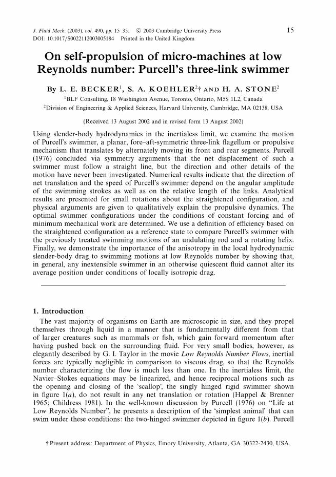
1. IntroductionThe vast majority of organisms on Earth are microscopic in size, and they propel
themselves through liquid in a manner that is fundamentally different from thatof larger creatures such as mammals or fish, which gain forward momentum afterhaving pushed back on the surrounding fluid. For very small bodies, however, aselegantly described by G. I. Taylor in the movie Low Reynolds Number Flows, inertialforces are typically negligible in comparison to viscous drag, so that the Reynoldsnumber characterizing the flow is much less than one. In the inertialess limit, theNavier–Stokes equations may be linearized, and hence reciprocal motions such asthe opening and closing of the ‘scallop’, the singly hinged rigid swimmer shownin figure 1(a), do not result in any net translation or rotation (Happel & Brenner1965; Childress 1981). In the well-known discussion by Purcell (1976) on “Life atLow Reynolds Number”, he presents a description of the ‘simplest animal’ that canswim under these conditions: the two-hinged swimmer depicted in figure 1(b). Purcell
† Present address: Department of Physics, Emory University, Atlanta, GA 30322-2430, USA.
16 L. E. Becker, S. A. Koehler and H. A. Stone
(a) y
x
I II
1
42
3
I II(b)
IV III
γ
γ
Figure 1. Simple configuration sequences for two hypothetical swimmers restricted to the(x, y)-plane: (a) the “scallop”, which has a single joint that is depicted opening with strokeangle γ to the straightened position, and (b)“Purcell’s swimmer”, which alternately rotates itstwo arms until the angle between them and the middle link equals ± γ .
indicated that a fore–aft-symmetric linkage with two hinges (three links) would movein a straight line over one cycle of alternately moving its front and rear links, butthe details of this motion were not investigated. Indeed the direction of motion wasleft as an exercise to the reader, but after more than two decades there still does notappear to be a satisfactory answer to that question (Castaing 1998). In this paper,we provide a detailed study of this simplest of hypothetical low-Reynolds-numberswimmers that are inextensible with rotating joints.
There exists considerable interest in studying the propulsive mechanics of commonmicro-organisms such as spermatozoa (e.g. Keller & Rubinow 1976a) and algae(e.g. Pedley & Kessler 1987) as well as their macroscopic collective dynamics (e.g. Hill,Pedley & Kessler 1989). Although the swimming strategies observed in nature aretypically more complicated than that of Purcell’s swimmer treated herein, a recentconjecture by Berg (2002) proposes that small helical bacteria called Spiroplasmasmight propel themselves in a manner similar to Purcell’s swimmer but with non-parallel axes of bending for the two idealized joints. Furthermore, recent advances inmicro-machines raise the possibility of deploying self-propelled micro-robots insidethe human body for minimally invasive therapeutic treatments (Iddan et al. 2000;Ishiyama et al. 2001a, b). The simplicity of Purcell’s swimmer may therefore provepractical in the design of micro-robots in addition to representing a useful model toexplore fundamental aspects of self-propulsion at low Reynolds numbers.
Early research on the planar motion of organisms at low Reynolds numberconsidered the propagation of plane waves along sheets and rods (e.g. Taylor 1951;Hancock 1953; Lighthill 1975), while more recent investigations have focused on thepropulsion produced by wave-like disturbances travelling along elastic filaments (e.g.Wiggins & Goldstein 1998; Camalet, Julicher & Prost 1999) and along surfaces of non-slender bodies (e.g. Blake 1971; Shapere & Wilczek 1989a, b; Stone & Samuel 1996;Ajdari & Stone 1999). Studies of non-planar motions of organisms have been confinedmainly to the propulsion of a helix rotating about its axis (e.g. Phan-Thien, Tran-Cong & Ramia 1987; Lighthill 1996; Purcell 1997), with some recent theoretical workon over-twisted elastica and their relation to experimentally observed super-coiledfilaments (plectonemes) produced by the bacterium B. subtilis (Goldstein, Powers &Wiggins 1998; Koehler & Powers 2000). Many of these existing models of swimmingmicro-organisms assume that the filament is infinitely long, that the amplitude of theshape perturbations is small, or that the idealized propulsive element is acted uponby some external force/torque. Conversely, given the inherent geometric simplicity ofPurcell’s swimmer, it is possible to model the large-amplitude motion of a physically
Self-propulsion of micro-machines 17
P
S1
S2
J
α
β
r
n
y
zx
Figure 2. A general, singly jointed swimmer, where surfaces/links S1 and S2 move as rigidbodies. The swimmer and its motion are confined to the (x, y)-plane.
realizable force-free linkage of slender bodies driven by internal motors acting at thejoints, as well as to determine the optimal swimmer for a given set of conditions.
In § 2, we use the linearity of the equations for the inertialess limit to derivethe equations governing the motion of a rigid linkage with only one mobile joint.These equations plus symmetry arguments are applied in § 3 to investigate thedetailed motion of Purcell’s swimmer. In § 4, we determine the optimal swimmingconfigurations for Purcell’s swimmer under the conditions of constant forcing andminimum mechanical work. We also propose a new efficiency criterion to comparePurcell’s swimmer to the undulating rod and the rotating helix. Finally, to demonstratethe importance of the anisotropy of the local fluid drag to swimming motions, wegive a simple proof that any inextensible swimmer in an otherwise quiescent fluidcannot swim under isotropic drag, a condition where the local hydrodynamic forceper unit length acting on the linkage is taken as directly proportional to the localfluid velocity. Our conclusions are summarized in § 5.
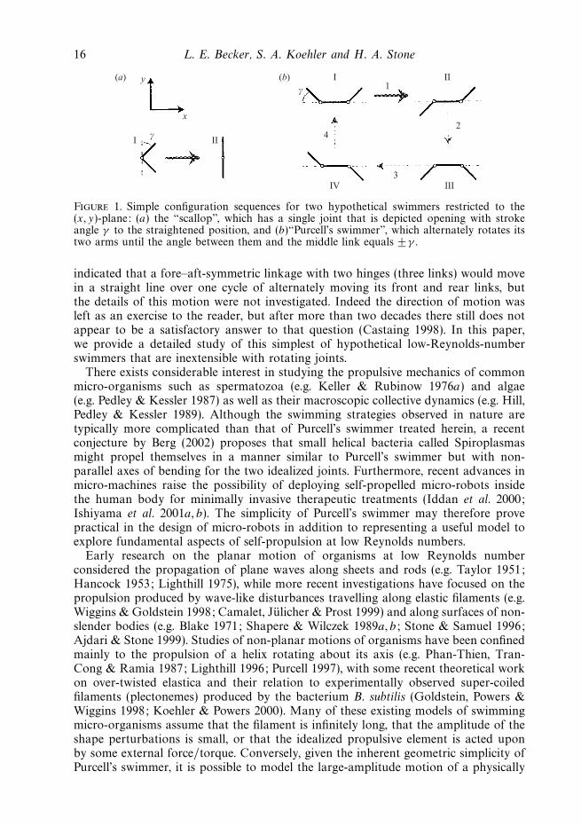
2. Single-joint dynamicsWe begin our study of micro-mechanical self-propulsion by examining the planar
one-joint slender linkage shown in figure 2. Without loss of generality, we onlyconsider motion in the (x, y)-plane. The velocity UP of any point P on the single-jointlinkage, relative to the fixed, inertial, Cartesian frame depicted in figure 2, may bedecomposed into three components: the velocity due to a translation of the joint J ,the velocity due to a rigid-body rotation about J , and the velocity due to a symmetric‘stretching motion’:
UP =
UJ + Ω ∧ r + ω ∧ r on S1
UJ + Ω ∧ r − ω ∧ r on S2,(1)
where r is the position vector from the joint J to point P , UJ is the velocity of thejoint, and the angular velocities Ω and ω are related to the time derivatives of theangles α and β defined in figure 2 by
Ω =
(α + β
2
)ez, ω =
(α − β
2
)ez, (2)
where ez is a unit vector in the z-direction. We wish to solve the continuity and Stokesequations,
∇ · u = 0, (3a)
∇ · σ = −∇p + µ∇2u = 0, (3b)
18 L. E. Becker, S. A. Koehler and H. A. Stone
for the slender linkage in an otherwise quiescent fluid, where (u, p, σ ) are the velocity,pressure, and stress fields, respectively. In the absence of externally applied forcefields, the swimmer overall is force- and torque-free. Motion is effected via equal butopposing moments between the two links, which are considered to move as rigidbodies. From elementary force and torque balances, with elimination of the force ofconstraint at the common joint J , a natural choice of generalized forces correspondingto the generalized velocities UJ , Ω and ω is the total force F ( = 0), the total momentL ( = 0) about J , and the torque difference between the links acting at J and drivingthe motion of the swimmer. More specifically, the linearity of the governing equationsimplies the following relation valid for arbitrarily shaped single-jointed objects (andgeneralizable in a straightforward fashion to an arbitrary number of joints):
RFURFΩRFω
RLURLΩRLω
RSURSΩRSω
UJ
Ωω
=
F =∫
SPn · σ dS
L =∫
SPr ∧ (n · σ ) dS
S =∫
S1r ∧ (n · σ ) dS −
∫S2
r ∧ (n · σ ) dS
=
0
0
−Sext
,
(4)
where the unit normal vector n of the (finite-thickness) links is directed into the fluid.Here Sext ≡ −S = Sextez is the torque difference or ‘strain forcing’ that the mecha-nism in the (x, y)-plane applies to the surrounding fluid, and represents the externaltorque applied to link S1 minus that on link S2. This strain forcing of the motionmay be thought of as resulting from a rubber band stretched across the active joint,or alternatively as twice the torque exerted by one side on the other via a motor, forexample.
The grand resistance matrix on the left-hand side of equation (4) may be shown tobe overall symmetric via the reciprocal theorem (Hinch 1972), so that, for example,RFU = RT
FU and RFΩ =RTLU . The individual resistance matrices of equation (4) depend
on the viscosity, size, and instantaneous configuration of the object, and thus uniquelydetermine the quantities UJ , Ω , and ω; here they will be computed according to (4)using the leading-order slender-body approximation (Batchelor 1970), which gives forexample that∫
Γ (s)
n · σ dΓ = −[
2πµ
ln(2/ε)
](2 I − λλ) · U(s) + O[ln−2(2/ε)], (5)
where s denotes arclength along the centreline, Γ (s) the circumference of the cross-section, µ the viscosity, ε the slenderness ratio of link diameter to its length, λ theunit tangent vector to the body, [2πµ/ ln(2/ε)] ≡ ζ represents an effective resistancecoefficient, and U(s) is the local velocity of the linkage. For example, with respect toa Cartesian reference frame, the first column of the sub-matrix RFU in the planar casecontains the x, y components of the total hydrodynamic force exerted on the linkageas a result of a pure rigid-body translation with unit velocity in the x-direction. Allcomponents of the grand resistance matrix are determined similarly by individuallyassigning unit velocities to the non-trivial components of UJ , Ω, and ω, a processwhich, for motion in the (x,y)-plane, reduces the governing matrix equation (4) to a4 × 4 system of equations, linear in the four unknown scalar velocities (UJ )x , (UJ )y ,Ω ≡ Ωz, and ω ≡ ωz.
As indicated in equation (5), the error involved in applying the leading-orderslender-body approximation to obtain an effective force density (per unit length)along the centreline is O[ln−2(2/ε)], which is only logarithmically smaller than theleading term. In fact, the initial corrections to the leading-order result have been
Self-propulsion of micro-machines 19
J
α
β
a
x
y
γ
C
b
a
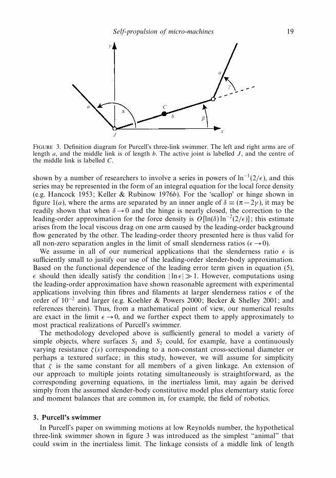
Figure 3. Definition diagram for Purcell’s three-link swimmer. The left and right arms are oflength a, and the middle link is of length b. The active joint is labelled J , and the centre ofthe middle link is labelled C.
shown by a number of researchers to involve a series in powers of ln−1(2/ε), and thisseries may be represented in the form of an integral equation for the local force density(e.g. Hancock 1953; Keller & Rubinow 1976b). For the ‘scallop’ or hinge shown infigure 1(a), where the arms are separated by an inner angle of δ ≡ (π − 2γ ), it may bereadily shown that when δ → 0 and the hinge is nearly closed, the correction to theleading-order approximation for the force density is O[ln(δ) ln−2(2/ε)]; this estimatearises from the local viscous drag on one arm caused by the leading-order backgroundflow generated by the other. The leading-order theory presented here is thus valid forall non-zero separation angles in the limit of small slenderness ratios (ε → 0).
We assume in all of our numerical applications that the slenderness ratio ε issufficiently small to justify our use of the leading-order slender-body approximation.Based on the functional dependence of the leading error term given in equation (5),ε should then ideally satisfy the condition | ln ε| 1. However, computations usingthe leading-order approximation have shown reasonable agreement with experimentalapplications involving thin fibres and filaments at larger slenderness ratios ε of theorder of 10−2 and larger (e.g. Koehler & Powers 2000; Becker & Shelley 2001; andreferences therein). Thus, from a mathematical point of view, our numerical resultsare exact in the limit ε → 0, and we further expect them to apply approximately tomost practical realizations of Purcell’s swimmer.
The methodology developed above is sufficiently general to model a variety ofsimple objects, where surfaces S1 and S2 could, for example, have a continuouslyvarying resistance ζ (s) corresponding to a non-constant cross-sectional diameter orperhaps a textured surface; in this study, however, we will assume for simplicitythat ζ is the same constant for all members of a given linkage. An extension ofour approach to multiple joints rotating simultaneously is straightforward, as thecorresponding governing equations, in the inertialess limit, may again be derivedsimply from the assumed slender-body constitutive model plus elementary static forceand moment balances that are common in, for example, the field of robotics.
3. Purcell’s swimmerIn Purcell’s paper on swimming motions at low Reynolds number, the hypothetical
three-link swimmer shown in figure 3 was introduced as the simplest “animal” thatcould swim in the inertialess limit. The linkage consists of a middle link of length
20 L. E. Becker, S. A. Koehler and H. A. Stone
b connected to two arms of equal length a; the arms alternately rotate by an angleof ± 2γ relative to, and in a manner that is symmetric about, the middle link, asindicated in figure 1(b) by the four configurations labelled I to IV. Purcell concludedfrom symmetry arguments that this two-joint mechanism does not undergo any netrotation over each complete cycle of the four arm strokes, and that each cycle resultsin a net translation along a straight line, but the direction of this translation and thenumerical details of this basic swimming motion have, to the best of our knowledge,never been determined.
Throughout the swimming cycle of Purcell’s swimmer, only one joint is activeat any one time, and hence the motion may be analysed using the methodologydeveloped in § 2. The grand resistance matrix of equation (4) for Purcell’s swimmerwas obtained and inverted using the symbolic manipulation software Maple, wherewe non-dimensionalized using a characteristic length scale a, velocity scale Sext/(ζa2),and time scale ζa3/Sext; from hereon, all quantities are to be taken as dimensionless,unless specified otherwise. The detailed motion may then be determined by simplyintegrating forward in time the resulting explicit relations for the generalizedvelocities.
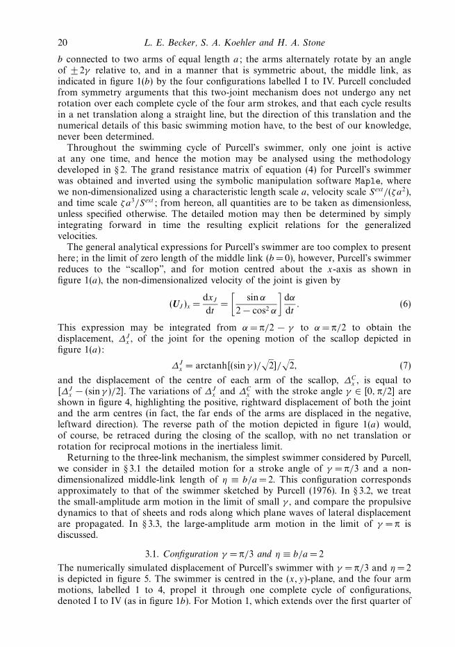
The general analytical expressions for Purcell’s swimmer are too complex to presenthere; in the limit of zero length of the middle link (b =0), however, Purcell’s swimmerreduces to the “scallop”, and for motion centred about the x-axis as shown infigure 1(a), the non-dimensionalized velocity of the joint is given by
(UJ )x =dxJ
dt=
[sinα
2 − cos2 α
]dα
dt. (6)
This expression may be integrated from α = π/2 − γ to α = π/2 to obtain thedisplacement, ∆J
x , of the joint for the opening motion of the scallop depicted infigure 1(a):
∆Jx = arctanh[(sin γ )/
√2]/
√2, (7)
and the displacement of the centre of each arm of the scallop, ∆Cx , is equal to
[∆Jx − (sin γ )/2]. The variations of ∆J
x and ∆Cx with the stroke angle γ ∈ [0, π/2] are
shown in figure 4, highlighting the positive, rightward displacement of both the jointand the arm centres (in fact, the far ends of the arms are displaced in the negative,leftward direction). The reverse path of the motion depicted in figure 1(a) would,of course, be retraced during the closing of the scallop, with no net translation orrotation for reciprocal motions in the inertialess limit.
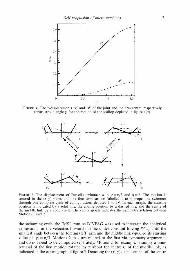
Returning to the three-link mechanism, the simplest swimmer considered by Purcell,we consider in § 3.1 the detailed motion for a stroke angle of γ = π/3 and a non-dimensionalized middle-link length of η ≡ b/a = 2. This configuration correspondsapproximately to that of the swimmer sketched by Purcell (1976). In § 3.2, we treatthe small-amplitude arm motion in the limit of small γ , and compare the propulsivedynamics to that of sheets and rods along which plane waves of lateral displacementare propagated. In § 3.3, the large-amplitude arm motion in the limit of γ = π isdiscussed.
3.1. Configuration γ = π/3 and η ≡ b/a =2
The numerically simulated displacement of Purcell’s swimmer with γ = π/3 and η = 2is depicted in figure 5. The swimmer is centred in the (x, y)-plane, and the four armmotions, labelled 1 to 4, propel it through one complete cycle of configurations,denoted I to IV (as in figure 1b). For Motion 1, which extends over the first quarter of
Self-propulsion of micro-machines 21
0
0.1
0.5 1.0 1.5
0.2
0.3
0.4
0.5
0.6
∆a
γ
∆xJ
∆xC
Figure 4. The x-displacements ∆Jx and ∆C
x of the joint and the arm centre, respectively,versus stroke angle γ for the motion of the scallop depicted in figure 1(a).
1
4
3
2
xx
xx
yy
yy
y
x
I I I
IV III
Rotate
by π
Time reversal
Figure 5. The displacement of Purcell’s swimmer with γ = π/3 and η = 2. The motion iscentred in the (x, y)-plane, and the four arm strokes labelled 1 to 4 propel the swimmerthrough one complete cycle of configurations denoted I to IV. In each graph, the startingposition is indicated by a solid line, the ending position by a dashed line, and the centre ofthe middle link by a solid circle. The centre graph indicates the symmetry relation betweenMotions 1 and 2.
the swimming cycle, the IMSL routine DIVPAG was used to integrate the analyticalexpressions for the velocities forward in time under constant forcing Sextez until thesmallest angle between the forcing (left) arm and the middle link equalled its startingvalue of |γ | = π/3. Motions 2 to 4 are related to the first via symmetry arguments,and do not need to be computed separately. Motion 2, for example, is simply a time-reversal of the first motion rotated by π about the centre C of the middle link, asindicated in the centre graph of figure 5. Denoting the (x, y) displacement of the centre
22 L. E. Becker, S. A. Koehler and H. A. Stone
0
0.1
1.25 2.50 3.75
0.2
0.3
0.4
0.5
0.6
∆a
tSext/(ζa3)
∆xJ
∆xC
5.00
–0.1
0
∆yC
∆yJ
1 2 3 4
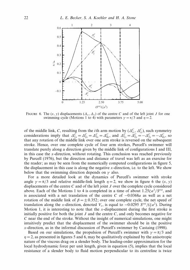
Figure 6. The (x, y) displacements (∆x,∆y) of the centre C and of the left joint J for oneswimming cycle (Motions 1 to 4) with parameters γ = π/3 and η = 2.
of the middle link, C, resulting from the ith arm motion by (∆Cix, ∆
Ciy), such symmetry
considerations imply that ∆C1x = ∆C
2x = ∆C3x =∆C
4x , and ∆C1y = ∆C
2y = −∆C3y = −∆C
4y , sothat any rotation of the middle link over one arm stroke is reversed on the subsequentstroke. Hence, over one complete cycle of four arm strokes, Purcell’s swimmer willtranslate purely along a direction given by the middle link of configurations I and III,in this case the x-direction, without rotating. This conclusion was reached previouslyby Purcell (1976), but the direction and distance of travel was left as an exercise forthe reader; as may be seen from the numerically computed configurations in figure 5,the displacement in this case is along the negative x-direction, i.e. to the left. We showbelow that the swimming direction depends on γ also.
For a more detailed look at the dynamics of Purcell’s swimmer with strokeangle γ = π/3 and relative middle-link length η = 2, we show in figure 6 the (x, y)displacements of the centre C and of the left joint J over the complete cycle consideredabove. Each of the Motions 1 to 4 is completed in a time of about 1.25ζa3/Sext, andis associated with a net translation of the centre C of −0.0368a as well as a netrotation of the middle link of β = ± 0.352; over one complete cycle, the net speed oftranslation along the x-direction, denoted Vx , is equal to −0.0295 Sext/(ζa2). DuringMotion 1, it is interesting to note that the x-displacement during the first stroke isinitially positive for both the joint J and the centre C, and only becomes negative forC near the end of the stroke. Without the insight of numerical simulations, one mightintuitively predict that the displacement of the swimmer should be in the positivex-direction, as in the informal discussion of Purcell’s swimmer by Castaing (1998).
Based on our simulations, the propulsion of Purcell’s swimmer with γ = π/3 andη = 2, as presented in figures 5 and 6, may be qualitatively explained by the anisotropicnature of the viscous drag on a slender body. The leading-order approximation for thelocal hydrodynamic force per unit length, given in equation (5), implies that the localresistance of a slender body to fluid motion perpendicular to its centreline is twice
Self-propulsion of micro-machines 23
that to motion along its centreline. Keeping this result in mind, we consider Motion 1,as the remaining steps of the swimming cycle follow from the first motion via thesymmetry considerations described above. During approximately the first half of theleft downward arm stroke, the active joint J and the centre C are displaced up and tothe right, similar to the motion of a scallop opening. The displacement to the right,however, is lessened by the far rigid arm, which is least aligned with the horizontaldirection at the start of Motion 1, but which progressively becomes more aligned dueto the clockwise rotation of the middle link. This clockwise rotation of the middlelink proceeds nearly linearly over the entire Motion 1, and thus over the secondhalf of the left arm stroke, where one would intuitively expect displacements thatare upward and to the left, the leftward motion is less restrained by the increasinglyaligned right rigid arm. By favouring motions that are tangential to it, the far armacts essentially like a rudder, enhancing the leftward movement of the middle link forsmall to moderate values of γ less than about π/2. This argument makes clear thatthe entire shape of the linkage is important for describing the motion.
Of course the two halves of the left downward arm stroke differ not only by thealignment of the far arm with the horizontal, but also by the cumulative rotation ofthe middle link itself. For stroke angles γ less than about π/2, the latter effect turnsout to be secondary, and the improved alignment of the far arm over each strokeis responsible for a net translation in the negative x-direction, i.e. to the left. Forlarge-amplitude arm strokes with γ → π, however, alignment of the far arm with thehorizontal in fact worsens over each arm stroke, the rotation of the middle link is thedefining feature of the motion, and Purcell’s swimmer undergoes a net translation inthe opposite direction, i.e. to the right, as shown and discussed later. In the next twosubsections, we consider first the small- and then the large-amplitude limits for thestroke angle γ .
3.2. Small-amplitude motion
Introducing θ ≡ π − α and expanding (using Maple software) the non-dimensionalizedsolution system represented by equation (4) about the fully extended configurationwith θ = β = γ = 0, we obtain the following expressions for the velocity of the jointJ and the angular rotation rates α and β corresponding to Motion 1 (i.e. the initialdownward stroke of the left arm):
(UJ )x = −3
4
[(β − θ)(η + 1) + γ
(η + 1)2
]+ O(γ 3), (8a)
(UJ )y =3
2(η +1)+O(γ 2), (8b)
α =3
4
(η + 4
η + 1
)+O(γ 2), (8c)
β = −3
4
[3η + 4
(η +1)3
]+O(γ 2). (8d)
Note that as the link ratio η ≡ b/a → ∞, UJ → 0, α → 3/4, and β → 0. The case η → 0,on the other hand, reduces to the scallop considered at the beginning of this section.
Next we determine the time interval ts , in units of ζa3/Sext, required for one stroke.Starting from the initial angles αi and βi , with γ = π − (αi − βi), the linearizedexpressions for α(t) and β(t) are integrated with respect to time. From the condition
24 L. E. Becker, S. A. Koehler and H. A. Stone
that the first quarter-cycle ceases when α − β = 2π − (αi − βi), it follows that
ts =
[8
3
γ (η + 1)3
(η + 4)(η +1)2 + 3η +4+ O(γ 2)
](ζa3
Sext
). (9)
Substituting for α and β with βi = 0 into (UJ )x and integrating from t = 0 to t = ts ,we can obtain the x-displacement over one quarter-cycle, and thus by symmetrythe average translational speed Vx , in units of Sext/(ζa2), of the swimmer over thecomplete swimming cycle:
Vx = −[3
8
η(2η + 3)γ
(η + 1)3(η + 2)+ O(γ 2)
](Sext
ζa2
). (10)
The translation of a swimmer, starting with βi = 0 as depicted in figure 5, is hence tothe left for linearized small-amplitude motions about the straightened configuration,regardless of the relative length of the middle link η (with Vx → 0 as η → 0 or ∞). Toleading order, the translation velocity is linear in the angular amplitude γ for a givenforcing of constant magnitude Sext acting alternately at the two joints.
Taylor (1951) and Hancock (1953) studied the propulsion of sheets and rods,respectively, along which plane waves of lateral displacement are propagated. Inthese studies, the small-amplitude translation velocity is equal to − 1
2χk2A2 plus
terms of higher order in kA, where A is the amplitude of the displacement, k is thewavenumber, and χ is the velocity of wave propagation. We can relate our small-amplitude results for Purcell’s swimmer to those obtained by Taylor and Hancock bycombining equations (9) and (10) to eliminate the forcing Sext:
Vx = −[
η(2η + 3)
(η + 2)[(η + 4)(η + 1)2 + 3η + 4]+ O(γ )
](a
ts
)(1
a
)2
(γ a)2. (11)
This expression for Purcell’s swimmer is analogous to the results by Taylor andHancock for small-amplitude plane-wave propulsion, if we take A∗ = γ a to be theamplitude of an equivalent wave, k∗ = 1/a as an effective wavenumber, and χ∗ = a/tsas an approximate wave speed that dictates how fast Purcell’s swimmer executeseach of the four motions of the swimming cycle. Equation (11) for the velocity ofPurcell’s swimmer can then be written as Vx = − 1
2f (η)χ∗k∗2
A∗2, but the magnitude ofthe factor f (η) is much smaller than the value of 1 corresponding to the plane-waveresult; given an aspect ratio of η = 1, for example, f (η) = 10/81.
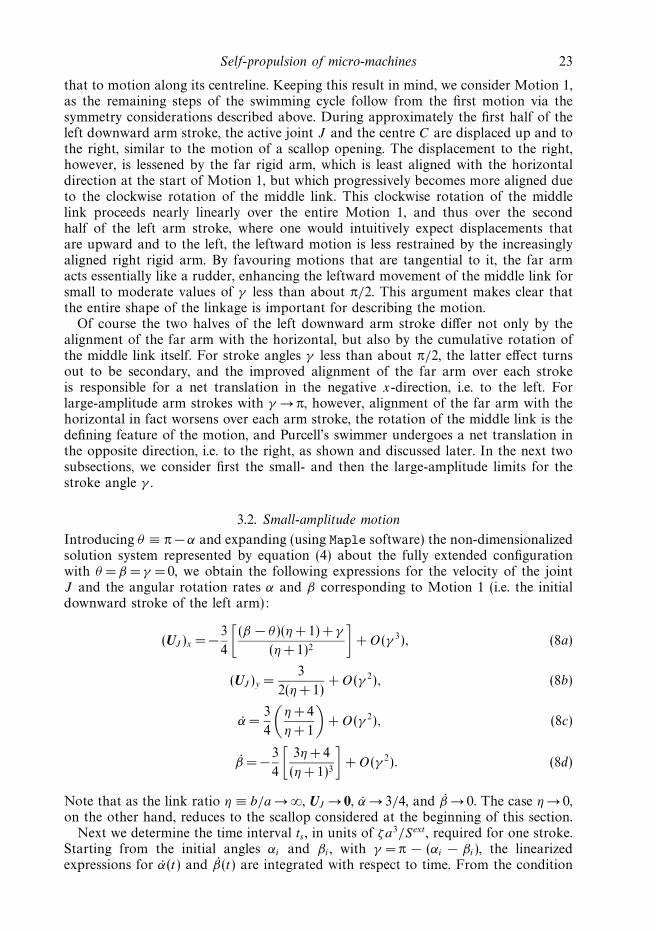
One can construct a reasonably good visual analogy for the case η =1 at any strokeamplitude γ < π/2 by superimposing the end points of the links of Purcell’s swimmerin configurations I to IV onto a rightward-travelling sinusoidal wave, as shown infigure 7. The rotation of Purcell’s swimmer in the figure is qualitatively similar towhat one would expect for its actual motion, suggesting that Purcell’s swimmer, atvalues of γ < π/2 where such an analogy is possible, corresponds approximately to onewavelength of a travelling wave. The rightward-travelling wave of lateral displacementcauses a net translation of the undulating rod to the left, and we will show in § 4.1that Purcell’s swimmer, swimming as indicated in figure 1(b), will also generallyswim to the left for stroke angles of γ 2, supporting the validity of this analogy.As we emphasized in our description of Purcell’s swimmer in § 3.1, Hancock (1953)similarly noted the importance of the anisotropy of the fluid drag for a qualitativeexplanation of the translation of the undulating rod in a direction opposite to that ofwave propagation: “. . . motions of small portions of cylinder normal to themselvestend to be in the backward direction while motions tangential to themselves tend
Self-propulsion of micro-machines 25
0
01
0.2 0.4 0.6 0.8 1.0–1
I
y
A
0
01
0.2 0.4 0.6 0.8 1.0–1
II
0
01
0.2 0.4 0.6 0.8 1.0–1
IV
y
A
0
01
0.2 0.4 0.6 0.8 1.0–1
III
x/λ x/λ
Figure 7. Analogy between Purcell’s swimmer and plane-wave propagation for an aspectratio of η =1. The end-points of the links in configurations I to IV are superimposed onto arightward-travelling sinusoidal wave.
to be in the forward direction, resulting in forward motion” (in this case, to theleft). This description of the propulsion of the undulating rod cannot be applieddirectly to Purcell’s swimmer, however, due to the latter’s relatively large up-and-down displacement perpendicular to the direction of travel (as given in figure 6 forγ = π/3 and η = 2). The dissimilarity is probably responsible for the poor quantitativeagreement between the translation velocity predicted for Purcell’s swimmer from thisanalogy and the true velocity of equation (11) (f (η) 1). One might further expectPurcell’s swimmer to be less efficient than plane-wave propulsion, an argument whichwe quantify in § 4.1 via the introduction of a new efficiency criterion.
3.3. Large-amplitude limit
In the previous two subsections, the arm motions of Purcell’s swimmer overconfigurations I to IV have resulted in a net translation in the negative x-direction,i.e. to the left. It turns out that for large-amplitude arm motions γ → π, where eacharm stroke consists of nearly a full rotation of the arm, our numerical results indicatethat the swimmer swims in the opposite direction, i.e. to the right. In the followingsection, we present a more complete overview of the variation of the net translationvelocity with stroke angle γ , while in this subsection we focus on some details ofthe motion when γ = π and the arms essentially start and finish on top of the centrelink. This limit of course violates slender-body theory, as lubrication forces eventuallydominate on close approach of any two surfaces. While our numerical computationsare only exact in the limit of small slenderness ratios, our calculated displacementsin the full-rotation limit γ = π will also apply in practical applications where thehydrodynamic interactions are important over only a small part of the configurationspace and yield corrections that are negligible relative to the overall motion; the timerequired to reach this limit, however, would be infinite based on the solution of theStokes equation for the approach of two locally flat surfaces, and hence we do notdiscuss propulsive velocities near γ = π.
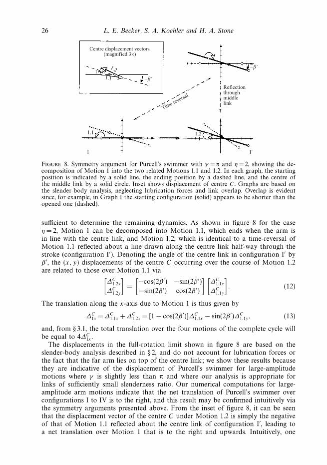
Additional symmetry arguments, independent of the hydrodynamic approximations,provide intuitive insight into the motion of Purcell’s swimmer in the large-amplitudelimit. As discussed in § 3.1, the motion of Purcell’s swimmer over any one completearm stroke may be related to that of any of the three other arm strokes via thesymmetry features depicted in figure 5. In the full-arm rotation limit γ = π, themotion of each stroke may in turn be broken down into two related motions, anddetailed knowledge of any one half-stroke (or one-eighth of the swimming cycle) is
26 L. E. Becker, S. A. Koehler and H. A. Stone
Centre displacement vectors(magnified 3×)
–β
11.2
1.1
1.1 1.2
I
Time reversal
–β
Reflectionthroughmiddlelink
I
Figure 8. Symmetry argument for Purcell’s swimmer with γ = π and η = 2, showing the de-composition of Motion 1 into the two related Motions 1.1 and 1.2. In each graph, the startingposition is indicated by a solid line, the ending position by a dashed line, and the centre ofthe middle link by a solid circle. Inset shows displacement of centre C. Graphs are based onthe slender-body analysis, neglecting lubrication forces and link overlap. Overlap is evidentsince, for example, in Graph I the starting configuration (solid) appears to be shorter than theopened one (dashed).
sufficient to determine the remaining dynamics. As shown in figure 8 for the caseη = 2, Motion 1 can be decomposed into Motion 1.1, which ends when the arm isin line with the centre link, and Motion 1.2, which is identical to a time-reversal ofMotion 1.1 reflected about a line drawn along the centre link half-way through thestroke (configuration I′). Denoting the angle of the centre link in configuration I′ byβ ′, the (x, y) displacements of the centre C occurring over the course of Motion 1.2are related to those over Motion 1.1 via[
∆C1.2x
∆C1.2y
]=
[−cos(2β ′) −sin(2β ′)
−sin(2β ′) cos(2β ′)
] [∆C
1.1x
∆C1.1y
]. (12)
The translation along the x-axis due to Motion 1 is thus given by
∆C1x = ∆C
1.1x +∆C1.2x = [1 − cos(2β ′)]∆C
1.1x − sin(2β ′)∆C1.1y, (13)
and, from § 3.1, the total translation over the four motions of the complete cycle willbe equal to 4∆C
1x .The displacements in the full-rotation limit shown in figure 8 are based on the
slender-body analysis described in § 2, and do not account for lubrication forces orthe fact that the far arm lies on top of the centre link; we show these results becausethey are indicative of the displacement of Purcell’s swimmer for large-amplitudemotions where γ is slightly less than π and where our analysis is appropriate forlinks of sufficiently small slenderness ratio. Our numerical computations for large-amplitude arm motions indicate that the net translation of Purcell’s swimmer overconfigurations I to IV is to the right, and this result may be confirmed intuitively viathe symmetry arguments presented above. From the inset of figure 8, it can be seenthat the displacement vector of the centre C under Motion 1.2 is simply the negativeof that of Motion 1.1 reflected about the centre link of configuration I′, leading toa net translation over Motion 1 that is to the right and upwards. Intuitively, one
Self-propulsion of micro-machines 27
might expect a qualitatively similar picture even if lubrication forces were taken intoaccount at finite values of the slenderness ratio.
While we have not undertaken a more detailed investigation incorporatinghydrodynamic interactions, in the full-rotation limit the centre link and the passivefolded-in arm would essentially behave as one; realistically, this effective link wouldhave a variable cross-section due to two arms lying side by side, but such variationshave a negligible effect on the hydrodynamics at sufficiently small slenderness ratios(Batchelor 1970). Thus, in the limit γ = π, Purcell’s swimmer over each stroke isessentially equivalent to a scallop with generally unequal arms. Neglect of the passivearm in our numerical simulations does not alter the qualitative features of the motionshown in figure 8. Corresponding to the case of equal arm lengths (η =1) in thefull-rotation limit, we have already shown in figure 4 that a scallop opening fromthe closed to the straight position – Motion 1.1 with neglect of the passive arm –experiences a positive, rightward displacement of the arm centres (∆C
1.1x > 0); bysymmetry, the same rightward displacement occurs as the scallop closes to the oppositeside (Motion 1.2), yielding ∆C
1x =2∆C1.1x > 0 and again supporting our conjecture that,
even at practically reasonable values of the slenderness ratio, Purcell’s swimmer in thelarge-amplitude limit should swim in a direction opposite to that for small-amplitudedisplacements.
4. Discussion4.1. Swimming velocity and propulsive efficiency
The question of which aspect ratio η and stroke angle γ results in the fastest or mostefficient Purcell’s swimmer depends on how one standardizes the energy-input criteriaacross different swimmer configurations. For very slow motions under relatively heavyload, muscles and machines generally dissipate much of their energy internally, andtheir power consumption depends to a large extent on the duration over which theyproduce a given force or torque, and less on the mechanical work performed on theenvironment; in the extreme case of zero net motion under load, as occurs whenholding a weight out in front of you or when pressing the accelerator just enough tobalance a car on a steep incline, no external work is done and all of the expendedenergy is transformed into heat. For a practical implementation of Purcell’s swimmeroperating under such conditions where internal energy dissipation is dominant, onepossible way to compare swimmer configurations is to let each swimmer exert aconstant torque difference Sext over time at either joint for a given arm lengtha, as was assumed in the previous section. Alternatively, under conditions whereinternal energy is transformed primarily into mechanical work, one could seek thefastest swimmer such that the mechanical power Φ = Sext(t)ω(t), which is dissipatedviscously in the fluid, remains constant over time.
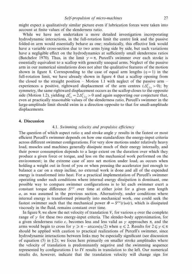
In figure 9, we show the net velocity of translation Vx for various η over the completerange of γ for these two energy-input criteria. The slender-body approximation, fora given slenderness ratio ε, becomes less and less valid as γ approaches π, and thearms would begin to cross for γ π − arccos(η/2) when η 2. Results for 2 γ πshould be applied with caution to practical realizations of Purcell’s swimmer, sincehydrodynamic interactions between links may be especially significant (see discussionof equation (5) in § 2); we focus here primarily on smaller stroke amplitudes wherethe velocity of translation is predominantly negative and the swimming sequencerepresented by configurations I to IV results in translation to the left. Our numericalresults do, however, indicate that the translation velocity will change sign for
28 L. E. Becker, S. A. Koehler and H. A. Stone
0 0.5
0
0.02
0.04
0.06(a)
–0.02
–0.06
–0.04
1.0 1.5 2.0 2.5 3.0
η = 1
2
1/4
1/2
V x(ζa
2 /S
ext )
0 0.5
0
0.02
0.04
0.06(b)
–0.02
–0.04
1.0 1.5 2.0 2.5 3.0
η = 2
1/4
1/2
V x(ζa
/Φ)1/
2
1
γ
Figure 9. The net velocity of translation Vx versus the stroke angle γ for various aspectratios η: (a) constant torque difference Sext, (b) constant mechanical power Φ .
large-amplitude motions (γ 2), and these findings are intuitively confirmed by thesymmetry arguments of § 3.3 for the complete-rotation (γ = π) limit shown in figure 8.
For the case of constant torque difference Sext shown in figure 9(a), the fastestPurcell’s swimmer translating in the negative x-direction has a configuration ofη = 0.58 and γ = 1.09, with a maximum rotation of the middle link of βmax = ± 0.81.The motion is qualitatively similar to the one shown in figure 5 for η = 2, and theoptimal swimmer has a translational velocity of Vx = −0.061Sext/(ζa2). Based solelyon the small-amplitude, linear analysis of § 3.2, the optimal aspect ratio would beη = 0.54.
For the case of constant mechanical power Φ = Sextω shown in figure 9(b), the fastestleft-moving swimmer has η =0.69, γ = 1.14, βmax = ± 0.80, and an average translation
Self-propulsion of micro-machines 29
velocity of Vx = −0.053(Φ/ζa)1/2; the small-amplitude analysis of § 3.2 predicts anoptimal aspect ratio of η =0.76. Since Φ may be written as some function ofinstantaneous configuration, g, times (Sext)2, where g = ω/Sext is one component of themobility matrix obtained from inversion of the resistance matrix in equation (4), theconstraint of constant mechanical power may be implemented by simply replacingthe forcing Sext in equation (4) by ±
√Φ/g and integrating as described in § 3 for
the case of constant forcing. Alternatively considering Φ as ω2/g, a quadratic formin angular velocities, it follows immediately from calculus of variations that thetotal mechanical work performed by Purcell’s swimmer while moving between twoarbitrary points in configuration space over any time interval [t1, t2] is minimizedunder constant mechanical power, i.e.
min
∫ t2
t1
Φ dt ⇒ Φ = constant. (14)
This result is completely analogous to that of conservation of energy in Lagrangianmechanics, where kinetic energy, instead of mechanical power, is of quadratic formin generalized velocities (see Landau & Lifshitz 1976); in the Appendix, we givea proof of equation (14) for the general case of an arbitrary, deformable volume.Thus the fastest swimmer configuration under constant mechanical power will requirethe least amount of mechanical work to swim a given distance over any fixed timeinterval.
Our determination of the fastest swimmer under either constant torque differenceSext or constant mechanical power Φ does not allocate greater torque or power toswimmers of larger aspect ratios η, a possibly fair comparison if the length of themiddle link is irrelevant to power generation within the swimmer. On the other hand,previous definitions of efficiency for low-Reynolds-number swimming motions haveaccounted for differences in length by comparing the power required to drag theswimmer at its translation velocity to the average mechanical power generated duringthe actual swimming motion (see Lighthill 1975 for the undulating sphere, Purcell1997 for the rotating helix). In this spirit, we define a swimming efficiency E as thepower necessary to pull the straightened swimmer (of length (η + 2) a) along its axisat the average speed of the actual swimmer, Vx , relative to the average mechanicalpower generated by the actual swimmer to achieve that speed, i.e.
E ≡ (η + 2)ζaV 2x
〈Φ〉 . (15)
Note that in the numerator of E we consider the power of pulling the straightenedswimmer as opposed to that of dragging some other fixed configuration. The definitionallows us to compare Purcell’s swimmer to the previously studied motions of theundulating rod and the rotating helix, as it may be applied universally to anyswimming slender body.
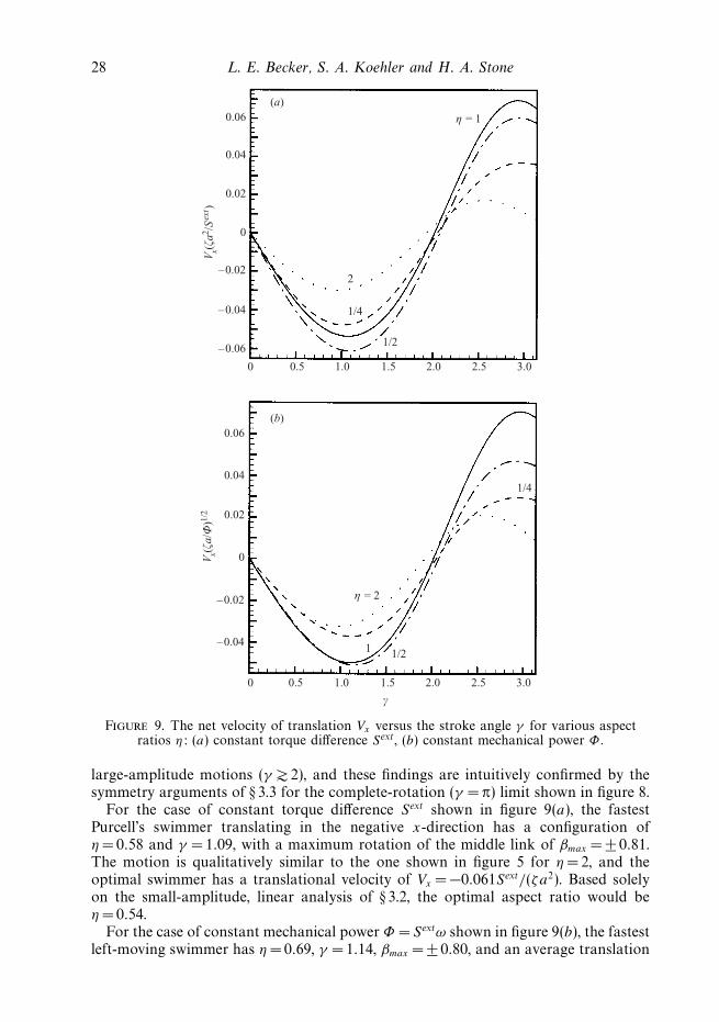
In figure 10, we plot the efficiency E versus stroke angle γ under constant mechanicalpower, a condition which, as noted above, minimizes the average mechanical powerrequired by any given swimmer configuration to achieve some specified net-translationvelocity Vx and which thus maximizes the efficiency of that swimmer. The efficienciesgiven in the figure correspond to the square of the velocities of figure 9(b), multipliedby the non-dimensionalized body length (η + 2). With this weighting in favour oflonger swimmers, the most efficient configuration for leftward propulsion has η =0.81,γ =1.13, and βmax = ±0.74, corresponding to an efficiency of Emax =0.00771. The
30 L. E. Becker, S. A. Koehler and H. A. Stone
0 0.5 1.0 1.5 2.0 2.5 3.0
η = 1
2
1/4
1/2
γ
0.0025
0.0050
0.0075
0.0100
0.0125
0.0150
Figure 10. The efficiency E versus the stroke angle γ for various aspect ratios η.
maximum efficiency for rightward propulsion is about twice as large at 0.0155,corresponding to a swimmer undergoing nearly full arm rotations with η = 0.93,γ = 2.98, and βmax = ±2.76, but this high value of the efficiency may not be realizedin practical implementations of Purcell’s swimmer due to hydrodynamic interactionsbetween links.
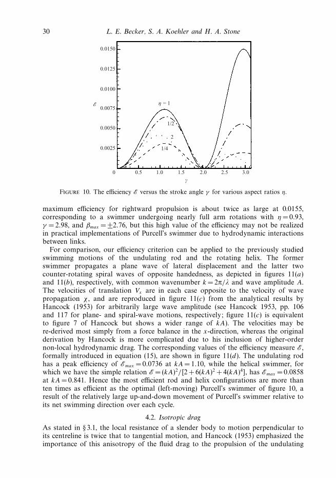
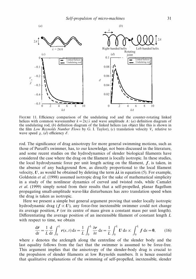
For comparison, our efficiency criterion can be applied to the previously studiedswimming motions of the undulating rod and the rotating helix. The formerswimmer propagates a plane wave of lateral displacement and the latter twocounter-rotating spiral waves of opposite handedness, as depicted in figures 11(a)and 11(b), respectively, with common wavenumber k = 2π/λ and wave amplitude A.The velocities of translation Vx are in each case opposite to the velocity of wavepropagation χ , and are reproduced in figure 11(c) from the analytical results byHancock (1953) for arbitrarily large wave amplitude (see Hancock 1953, pp. 106and 117 for plane- and spiral-wave motions, respectively; figure 11(c) is equivalentto figure 7 of Hancock but shows a wider range of kA). The velocities may bere-derived most simply from a force balance in the x-direction, whereas the originalderivation by Hancock is more complicated due to his inclusion of higher-ordernon-local hydrodynamic drag. The corresponding values of the efficiency measure E,formally introduced in equation (15), are shown in figure 11(d). The undulating rodhas a peak efficiency of Emax = 0.0736 at kA= 1.10, while the helical swimmer, forwhich we have the simple relation E =(kA)2/[2 + 6(kA)2 + 4(kA)4], has Emax =0.0858at kA= 0.841. Hence the most efficient rod and helix configurations are more thanten times as efficient as the optimal (left-moving) Purcell’s swimmer of figure 10, aresult of the relatively large up-and-down movement of Purcell’s swimmer relative toits net swimming direction over each cycle.
4.2. Isotropic drag
As stated in § 3.1, the local resistance of a slender body to motion perpendicular toits centreline is twice that to tangential motion, and Hancock (1953) emphasized theimportance of this anisotropy of the fluid drag to the propulsion of the undulating
Self-propulsion of micro-machines 31
0 2 4 6 8 10kA
0
–0.1
–0.2
–0.3
–0.4
–0.5
Undulating rodLinked helices
2A
(a)λ
λ = 2π/k
0 2 4 6 8 10kA
0.1
0.08
Undulating rodLinked helices
2A
(b)
Left-handed helixRight-handed helixRotating
joint
0.06
0.04
0.02
(c) (d)
Vx
χ
Figure 11. Efficiency comparison of the undulating rod and the counter-rotating linkedhelices with common wavenumber k = 2π/λ and wave amplitude A: (a) definition diagram ofthe undulating rod, (b) definition diagram of the linked helices (an object like this is shown inthe film Low Reynolds Number Flows by G. I. Taylor), (c) translation velocity Vx relative towave speed χ , (d) efficiency E.
rod. The significance of drag anisotropy for more general swimming motions, such asthose of Purcell’s swimmer, has, to our knowledge, not been discussed in the literature,and some recent studies on the hydrodynamics of slender biological filaments haveconsidered the case where the drag on the filament is locally isotropic. In these studies,the local hydrodynamic force per unit length acting on the filament, f , is taken, inthe absence of any background flow, as directly proportional to the local filamentvelocity, U , as would be obtained by deleting the term λλ in equation (5). For example,Goldstein et al. (1998) assumed isotropic drag for the sake of mathematical simplicityin a study of the nonlinear dynamics of curved and twisted rods, while Camaletet al. (1999) simply noted from their results that a self-propelled, planar flagellumpropagating small-amplitude wave-like disturbances has zero translation speed whenthe drag is taken as isotropic.
Here we present a simple but general argument proving that under locally isotropichydrodynamic drag ( f ∝ U), any force-free inextensible swimmer could not changeits average position, r (or its centre of mass given a constant mass per unit length).Differentiating the average position of an inextensible filament of constant length L
with respect to time, we obtain
drdt
=1
L
d
dt
∫ L
0
r(s, t) ds =1
L
∫ L
0
∂ r∂t
ds =1
L
∫ L
0
U ds ∝∫ L
0
f ds = 0, (16)
where s denotes the arclength along the centreline of the slender body and thelast equality follows from the fact that the swimmer is assumed to be force-free.This argument implies that the anisotropy of the slender-body drag is crucial tothe propulsion of slender filaments at low Reynolds numbers. It is hence essentialthat qualitative explanations of the swimming of self-propelled, inextensible, slender
32 L. E. Becker, S. A. Koehler and H. A. Stone
bodies in the inertialess limit, such as the intuitive description of the motion ofPurcell’s swimmer given in § 3.1, incorporate the inherent drag anisotropy, withoutwhich swimming would be impossible.
5. ConclusionsPurcell (1976) introduced the three-link swimmer as the simplest ‘animal’ or
mechanism that could swim at low Reynolds number, but the swimming directionwas left as a question for the reader. Our numerical results, based on leading-order slender-body hydrodynamics, show that Purcell’s swimmer can travel in eitherdirection along a straight line depending upon the amplitude of the arm motions. Forsmall to moderate stroke angles of the arms (γ 2), Purcell’s swimmer is qualitativelysimilar to approximately one wavelength of an undulating rod propagating a plane-wave disturbance, and the swimming direction is opposite to that of the wavevelocity; for larger stroke amplitudes, the direction of net translation reverses. Thefastest swimmer configurations under the conditions of constant forcing and ofminimum mechanical work were determined. Via a new efficiency criterion, wecompared Purcell’s swimmer to the undulating rod and the rotating helix; it wasshown that the optimal swimmer has an efficiency of only about 0.77%, and so ismuch less efficient than the optimal undulating rod (7.4%) and the rotating helix(8.6%). Finally, we also proved that under the simplifying assumption of locallyisotropic drag, a self-propelled inextensible filament in an otherwise quiescent fluidcannot translate its average position, demonstrating the central importance of draganisotropy to swimming motions in the inertialess limit.
L.E.B. acknowledges support from DOE grant DE-FG02-88ER25053, and H.A.S.acknowledges grant DAAG 55-97-1-0114 from the Army Research Office as wellas grant ECS-0004030 from the National Science Foundation. H.A.S. thanksA. Samuel for numerous helpful discussions about swimming micro-organisms. Wethank R. Day, T. Squires and H. Berg for discussions.
Appendix. Minimum mechanical workIn this Appendix, we consider a continuous, freely deformable volume with
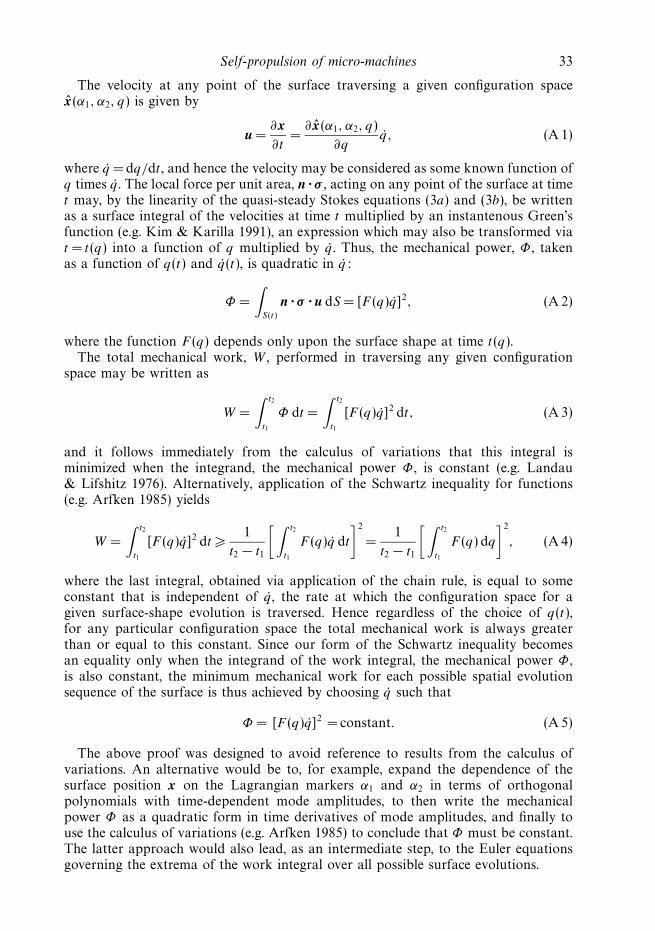
bounding surface S that evolves, in an otherwise quiescent fluid under the inertialess(zero-Reynolds-number) regime, between two arbitrary surface positions x1 and x2 ina given time interval [t1, t2]. We then demonstrate that among all possible displacementstrategies, the one that minimizes the total mechanical work must have constantmechanical power throughout the motion.
Let each point of the surface be mapped onto a pair of Lagrangian markercoordinates α1 and α2, so that the position on the surface is described by the positionvector x = x(α1, α2, t). Consider one particular evolution x = x of the surface betweenx(t = t1) = x1 and x(t = t2) = x2. Based on this motion, define a configuration spacex(α1, α2, q), q ∈ [t1, t2], where the variable q parameterizes this particular sequenceof surface shapes. This configuration space may be traversed by the volume in timeat different rates, as specified by the function q(t) with q(t = t1) = t1 and q(t = t2) = t2.We will show that for such a configuration space corresponding to any one of allpossible spatial evolutions of the surface between x1 and x2, the total mechanicalwork is minimized by choosing the function q(t) such that the mechanical power isconstant.
Self-propulsion of micro-machines 33
The velocity at any point of the surface traversing a given configuration spacex(α1, α2, q) is given by
u =∂x∂t
=∂ x(α1, α2, q)
∂qq, (A 1)
where q =dq/dt , and hence the velocity may be considered as some known function ofq times q . The local force per unit area, n · σ , acting on any point of the surface at timet may, by the linearity of the quasi-steady Stokes equations (3a) and (3b), be writtenas a surface integral of the velocities at time t multiplied by an instantenous Green’sfunction (e.g. Kim & Karilla 1991), an expression which may also be transformed viat = t(q) into a function of q multiplied by q . Thus, the mechanical power, Φ , takenas a function of q(t) and q(t), is quadratic in q:
Φ =
∫S(t)
n · σ · u dS = [F (q)q]2, (A 2)
where the function F (q) depends only upon the surface shape at time t(q).The total mechanical work, W , performed in traversing any given configuration
space may be written as
W =
∫ t2
t1
Φ dt =
∫ t2
t1
[F (q)q]2 dt, (A 3)
and it follows immediately from the calculus of variations that this integral isminimized when the integrand, the mechanical power Φ , is constant (e.g. Landau& Lifshitz 1976). Alternatively, application of the Schwartz inequality for functions(e.g. Arfken 1985) yields
W =
∫ t2
t1
[F (q)q]2 dt 1
t2 − t1
[ ∫ t2
t1
F (q)q dt
]2
=1
t2 − t1
[ ∫ t2
t1
F (q) dq
]2
, (A 4)
where the last integral, obtained via application of the chain rule, is equal to someconstant that is independent of q , the rate at which the configuration space for agiven surface-shape evolution is traversed. Hence regardless of the choice of q(t),for any particular configuration space the total mechanical work is always greaterthan or equal to this constant. Since our form of the Schwartz inequality becomesan equality only when the integrand of the work integral, the mechanical power Φ ,is also constant, the minimum mechanical work for each possible spatial evolutionsequence of the surface is thus achieved by choosing q such that
Φ = [F (q)q]2 = constant. (A 5)
The above proof was designed to avoid reference to results from the calculus ofvariations. An alternative would be to, for example, expand the dependence of thesurface position x on the Lagrangian markers α1 and α2 in terms of orthogonalpolynomials with time-dependent mode amplitudes, to then write the mechanicalpower Φ as a quadratic form in time derivatives of mode amplitudes, and finally touse the calculus of variations (e.g. Arfken 1985) to conclude that Φ must be constant.The latter approach would also lead, as an intermediate step, to the Euler equationsgoverning the extrema of the work integral over all possible surface evolutions.
34 L. E. Becker, S. A. Koehler and H. A. Stone
REFERENCES
Ajdari, A. & Stone, H. A. 1999 A note on swimming using internally generated traveling waves.Phys. Fluids 11, 1275–1277.
Arfken, G. 1985 Mathematical Methods for Physicists. Academic.
Batchelor, G. K. 1970 Slender-body theory for particles of arbitrary cross-section in Stokes flows.J. Fluid Mech. 44, 419–440.
Becker, L. E. & Shelley, M. J. 2001 Instability of elastic filaments in shear flow yields first-normal-stress differences. Phys. Rev. Lett. 87, art. 198301.
Berg, H. C. 2002 How Spiroplasma might swim. J. Bacteriol. 184, 2063–2064.
Blake, J. R. 1971 A spherical envelope approach to ciliary propulsion. J. Fluid Mech. 46,199–208.
Camalet, S., Julicher, F. & Prost, J. 1999 Self-organized beating and swimming of internallydriven filaments. Phys. Rev. Lett. 82, 1590–1593.
Castaing, B. 1998 An introduction to hydrodynamics. In Hydrodynamics and Nonlinear Instabilities(ed. C. Godreche & P. Manneville). Cambridge University Press.
Childress, S. 1981 Mechanics of Swimming and Flying. Cambridge University Press.
Goldstein, R. E., Powers, T. R. & Wiggins, C. H. 1998 Viscous nonlinear dynamics of twist andwrithe. Phys. Rev. Lett. 80, 5232–5235.
Hancock, G. J. 1953 The self-propulsion of microscopic organisms through liquids. Proc. R. Soc.Lond. A 217, 96–121.
Happel, J. & Brenner, H. 1965 Low Reynolds Number Hydrodynamics. Prentice-Hall.
Hill, N. A., Pedley, T. J. & Kessler, J. O. 1989 Growth of bioconvection patterns in asuspension of gyrotactic micro-organisms in a layer of finite depth. J. Fluid Mech. 208,509–543.
Hinch, E. J. 1972 Note on the symmetries of certain material tensors for a particle in Stokes flow.J. Fluid Mech. 54, 423–425.
Iddan, G., Meron, G., Glukhovsky, A. & Swain, P. 2000 Wireless capsule endoscopy. Nature 405,417.
Ishiyama, K., Sendoh, M., Yamazaki, A., Inoue, M. & Arai, K. I. 2001a Swimming of magneticmicro-machines under a very wide range of Reynolds number conditions. IEEE Trans. Magnet.37, 2868–2870.
Ishiyama, K., Sendoh, M., Yamazaki, A. & Arai, K. I. 2001b Swimming micro-machine driven bymagetic torque. Sensor Actuat. A-Phys. 91, 141–144.
Keller, J. B. & Rubinow, S. I. 1976a Swimming of flagellated microorganisms. Biophys. J. 16,151–170.
Keller, J. B. & Rubinow, S. I. 1976b Slender-body theory for slow viscous flow. J. Fluid Mech. 75,705–714.
Kim, S. & Karrila, S. J. 1991 Microhydrodynamics: Principles and Selected Applications.Butterworth-Heinemann.
Koehler, S. A. & Powers, T. R. 2000 Twirling elastica: Kinks, viscous drag and torsional stress.Phys. Rev. Lett. 85, 4827–4830.
Landau, L. D. & Lifshitz, E. M. 1976 Mechanics. Pergamon.
Lighthill, J. 1975 Mathematical Biofluiddynamics. Regional Conference Series in Applied Mathe-matics, vol. 17, SIAM.
Lighthill, J. 1996 Helical distribution of stokeslets. J. Engng Maths 30, 35–78.
Pedley, T. J. & Kessler, J. O. 1987 The orientation of spheroidal microorganisms swimming in aflow field. Proc. R. Soc. Lond. B 231, 47–70.
Phan-Thien, N., Tran-Cong, T. & Ramia, M. 1987 A boundary-element analysis of flagellarpropulsion. J. Fluid Mech. 184, 533–549.
Purcell, E. M. 1977 Life at low Reynolds number. Am. J. Phys. 45, 3–11.
Purcell, E. M. 1997 The efficiency of propulsion by a rotating flagellum. Proc. Natl Acad. Sci. 94,11307–11311.
Shapere, A. & Wilczek, F. 1989a Geometry of self-propulsion at low Reynolds number. J. FluidMech. 198, 557–585.
Self-propulsion of micro-machines 35
Shapere, A. & Wilczek, F. 1989b Efficiencies of self-propulsion at low Reynolds number. J. FluidMech. 198, 587–599.
Stone, H. A. & Samuel, A. D. T. 1996 Propulsion of microorganisms by surface distortions. Phys.Rev. Lett. 77, 4102–4104.
Taylor, G. I. 1951 Analysis of the swimming of microscopic organisms. Proc. R. Soc. Lond. A 209,447–461.
Wiggins, C. H. & Goldstein, R. E. 1998 Flexive and propulsive dynamics of elastica at lowReynolds numbers. Phys. Rev. Lett. 80, 3879–3882.