Embed Size (px)
Citation preview

ACCEPTED BY IEEE JOURNAL OF OCEANIC ENGINEERING 1
On the Design of Single-Point Cable-LinkedMoorings for Ocean Observatories
Seon Han and Mark Grosenbaugh
Abstract
The goal of this study is to provide design criteria for moorings proposed for long-term ocean observatories that use electro-optical-mechanical (EOM) cables and to identify the parameters that affect their dynamics. The EOM cables are much stiffer than traditionalmooring lines, and therefore, the moorings may experience higher loads under most environmental conditions if not designed properly. Weconsider two designs that provide geometric compliance yet keep all the cable in the water column. One of the designs uses a single subsurfacefloat with an “S-tether” positioned above it. The other design uses distributed buoyancy to create an S-tether in the lower half of the mooringline. Both designs use an elastomeric snubber hose attached in-line just below the buoy. The maximum tensions in the hose and at theanchor, and Raoof’s contact stress-slip parameter at critical locations are used to evaluate the designs. Our results show that the mostimportant design parameter in terms of the maximum tensions is the length of the mooring, the most important parameters in terms of thebending fatigue damage is the length of the buoyant section and the distribution of cable floats, and the most important design parameterin terms of the dynamic motion of the cable is the length of the snubber hose. In the design with a subsurface float, it is shown that thereexists an optimum S-tether length that minimizes the maximum tensions for a given subsurface float depth. The general rule of thumb thatthe S-tether be about twice the depth of the subsurface float breaks down when the subsurface float is placed near the surface. In general,the design with a subsurface float should be used if a small watch circle and small tension in the snubber are required. The design withouta subsurface float is preferred if small overall tension along the length of the mooring is required, if the bending fatigue failure is of concern,and if a longer smooth section of the cable below the surface buoy for use with a profiler is required. In both designs, the snubber lengthshould be at least 30m so that the dynamic motion is kept reasonably small.
Keywords
Oceanographic moorings; moored ocean observatories; EOM cable; S-tether; inverse catenary.
I. I����������
Over the next decade, much of oceanographic research will be conducted using long-term measurements from oceanobservatories [1] [2] [3] [4]. The observatories will consist of suites of instruments mounted near the ocean surface, in thewater column, and on the sea floor. A major component of the observatory system will be moored surface buoys, whichwill provide high bandwidth “real-time” two-way communication links via satellite to remote sites around the world’soceans. The proposed mooring systems include tri-moored spar buoys that will be deployed for up to 10 years and moreportable single-point moorings that will be deployed for 3-5 years. In this paper, we concentrate on the single-pointmoorings by providing a quantitative framework for their design.The single-point moorings that are proposed for ocean observatories will use an electro-optical-mechanical (EOM)
cable as the mooring line. This is used to send power from the buoy to the sea floor and transmit data from theinstruments to the buoy. The material used in EOM cables is typically much stiffer than that used in traditionaloceanographic mooring lines, which consist of long lengths of nylon for elastic compliancy. Because of higher elasticstiffness, a mooring made from an EOM cable will experience higher loads under most current and wave conditions.Also, failures in the communication and power paths can occur, regardless of the integrity of the cable itself, due toa mismatch between the stress-strain characteristics of the EOM cable’s strength member and the internal bundles ofcopper conductors and optical fibers [5].In this paper, we have chosen to analyze two single-point mooring designs that are being considered for observatory
mooring systems [1] with the idea of optimizing parameters that effect the failure of the mooring line and the internalconductors and fibers. These single-point moorings use solar panels on the buoy for power production and can transmitto shore up to 5 Mbytes of data per day. They are relatively cheap to build (compared to the tri-moored spar buoysystem) and easy to deploy requiring only a single ship. The first design uses an “S-tether” positioned above subsurfacefloat (SSF) (Fig. 1a). The S-tether is an EOM cable (as is the mooring line below the SSF) that is made positivelybuoyant (by attaching flotation) over roughly half of the cable and made negatively buoyant (by using steel-armoredcable or attaching weights) over the other half of the cable. In light to moderate currents, the tether above the SSFforms an S-shape. The second design has a more traditional inverse catenary shape (without a SSF) which is formed byattaching flotation over the lower part of the mooring. The idea behind the S-tether and inverse catenary shapes is toincrease the scope while preventing excess mooring line from chafing on the sea bottom in low currents. In both cases,an elastomeric hose is attached in-line below the buoy to increase elastic compliance in waves [5].An early mention of an S-shaped mooring line with a SSF for oceanographic use appears in Evans and Adamchack
[6], where such a line is referred to as a slack mooring. A similar terminology was used by Berteaux [7] for an inversecatenary mooring (without a SSF) made from a combination of polypropylene and nylon ropes. The National Data Buoy
Seon Han is currently an assistant professor at Texas Tech University, and Mark Grosenbaugh is an associate scientist at Woods HoleOceanographic Institution.

ACCEPTED BY IEEE JOURNAL OF OCEANIC ENGINEERING 2
(a) Mooring design with a subsurface float
(b) Mooring design without a subsurface float
subsurface float
rubber hosesnubber
cable floats
steel-armored cable
surface buoy
armor-covered Vectran cable
cable floats
Vectran cable
Fig. 1. Schematics of two mooring systems proposed for ocean observatories
Center (NDBC) has been using inverse catenary moorings for coastal observation moorings in water depth greater than600m [8]. The oil industry has adopted S-shapes in the design of flexible risers since 1978, when flexible risers were firstspecified and installed in the Enchova field, offshore of Brazil, as part of a floating production system [9]. Some of thebasic configurations currently in service are the lazy-S, lazy-wave, steep-S and steep-wave. The guidelines for installingsuch flexible pipes can be found in the publication RP-17B of the American Petroleum Institute [10]. Seyed and Patel[11] conducted a parametric study on these four types of flexible riser configurations for offshore petroleum applications.The design issues for single-point oceanographic moorings that use EOM cables differ from those found in offshore
oil industry because of the small diameter cables that are used and fact that the EOM cables must serve as thestrength element in accommodating both dynamic motion and static offset. So far, the design of S-shaped tethers foroceanographic moorings has involved guess work without really knowing what effect changing the different parametershas on the cable motions and mooring forces. For example, it is not clear how deep the SSF should be placed and howbuoyant it should be. Or, what is the effect of not using a SSF at all. Additional questions regarding the S-tethers andinverse catenary shapes are: how long should the mooring line be, what percentage of its length should be positivelybuoyant and what percentage should be negatively buoyant, how buoyant should the buoyant section be, and how heavyshould the weighted section be.The purpose of this work is to provide answers to these questions by evaluating the motion, the tension, and the
fatigue damage of EOM mooring cables of single-point ocean observatory moorings subjected to current, wind, andrandom waves. Fatigue damage is estimated using by Raoof’s contact stress-slip parameter defined in the subsequentsection. Raoof’s results are applicable in the strictest sense to steel armored cables, which are used in the upper sectionof the mooring with a SSF. For synthetic mooring cables, which are used in the inverse catenary design and in thelower section of the mooring with a SSF, we make the assumption that the results can be applied in a relative sense(comparing two different mooring designs) though more research on the fatigue of synthetic cables is needed.
II. R���’� R �����
For a uniform rod, the bending moment is proportional to the curvature. The maximum stress due to bending occursin the outer fiber, furthest away from the neutral axis. In the case of a strand of wire rope (with a king wire at the centerand the layers of wires wound around it), it is tempting to calculate the stresses in the individual wires by assumingthat they are uniform rods with negligible friction between them. However, experimental data show that when a strandfails in bending, it almost always fails near the neutral axis of the cable [10], where the relative motion between theouter two layers is the largest. This reveals that the friction must play an important role in the bending fatigue ofcables. In fact, failure is due to the stress caused by the inter-layer fretting or sawing actions between the two layers.The fatigue damage caused by inter-layer fretting depends on the relative motion between the two layers. The relativemotion increases with increasing amplitude of alternating curvature. For a cable under constant tension and alternatingcurvature (from κ to -κ), Raoof [12] [13] [14] [15] showed experimentally that a single S-N curve could be drawn interms of the “contact stress-slip parameter” for cables with various dimensions and construction methods. The contactstress-slip parameter depends on the construction method (lay angles, wire radii, helix angle, etc.), mean axial strain,and the alternating curvature. The contact stress-slip parameter, which we will denote as Λ, is given by
Λ =σxUxx
, (1)

ACCEPTED BY IEEE JOURNAL OF OCEANIC ENGINEERING 3
0 0.1 0.2 0.3 0.4 0.5 0.6 0.7-4000
-3500
-3000
-2500
-2000
-1500
-1000
-500
0
Wat
erde
pth
()
m
Current speed ( )m/s
survival current
design current
slack current
wind speed 0 10 20m/s m/s m/s
significant wave height 0 (period)
m 4.5 (12 ) 13 (19 )m s m s
slack design survival
Fig. 2. Current profile
where σx is the normal stress which largely depends on the mean strain of the cable, x is the contact patch spacing,and Ux is the increase of x during bending of the cable and largely depends on the curvature. Raoof describes how toobtain these quantities for a given strand of steel cable [12] [13] [14] [15].Raoof’s result is for cables that are subjected to constant tension and alternating constant amplitude curvature with
zero mean. In our case, the mean tension is slowly varying and can be assumed constant. However, the curvature variesrandomly with time about non-zero mean curvature. No research has been done to assess the effect that non-zero meancurvature or random loading has on the bending fatigue of cables. However, the goal of this study is not to predict thefatigue life of a given mooring system but to compare various designs. For example, if both the mean and the standarddeviation of Λ of a certain design are smaller than those of another design, it can be concluded that it is a better design.In this paper, we will plot the mean and the standard deviation of the contact stress-slip parameter at critical locationsalong the mooring cable.
III. D ��� A�����
Responses of the moored buoy systems are obtained using WHOI Cable, a general-purpose numerical code that wasdeveloped at Woods Hole Oceanographic Institution for calculating the static and dynamic response of moored and towedoceanographic systems [16]. The finite difference time domain simulation is built around a mathematical model of cabledynamics. The cable model is fully three-dimensional and includes the effects of torsion, bending, and geometric andmaterial nonlinearities. The code has undergone extensive verification on a number of different cable systems [17][18].We assume that the vertical displacement of the surface buoy follows the wave elevation, which is described by a
modified Pierson-Moskowitz spectrum. This assumption is valid because the proposed buoy shapes all have large water-plane areas relative to their virtual mass. The current velocity profile, wind velocities, and significant wave heightsthat are used in the analysis are shown in Fig. 2. Values are given for slack water conditions, design conditions (theconditions that are expected to be exceeded 10% of the time), and survival conditions (25-year return storm). Thesevalues correspond to conditions that would be found along the Northern California coast, where sea floor observatorysites have been proposed. The design drivers are the maximum tension in the snubber hose, the maximum tension atthe anchor, and the maximum bending fatigue along the mooring line. In each case, the maximum is defined as themean value plus four times the standard deviation.
A. Mooring with a Subsurface Float
The properties of the baseline design with SSF are given in Appendix A. The baseline design consists of a surfacebuoy followed by a 30m elastic snubber hose, 700m steel-armored EOM cable, 700m steel-armored EOM cable withthirty six 272N (61lb) cable floats (they clamp directly onto the cable without releasing bending moments) placed at 20mintervals, 5m chain potted in polyurethane and covered with tygon tubing (used at cable terminations), SSF with 10200N(2300lb) buoyancy, 5m potted chain, 2990m Vectran EOM cable, 5m potted chain, and a 2730kg (6000lb) anchor. Thewet weights of the buoyant section (with attached flotation) and the weighted section are about ±6.80N/m, respectively.The baseline water depth of 3700m was chosen to correspond with the Northern California location identified by Chaffeyet al. [3] as a possible deployment site for their system. The scope of the baseline system is 1.2.Fig. 3 shows the static configurations of the baseline mooring under the slack, design, and survival current and wind
ACCEPTED BY IEEE JOURNAL OF OCEANIC ENGINEERING 4
0 0.5 1 1.5 2 2.50
0.5
1
1.5
2
2.5
3
3.5
4
Horizontal distance ( )km
Ver
tical
dist
ance
from
the
anch
or (
)km
survival
designslack
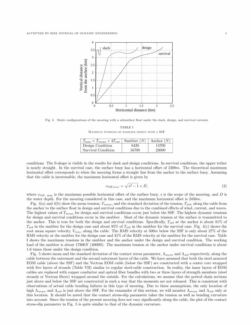
Fig. 3. Static configurations of the mooring with a subsurface float under the slack, design, and survival currents
TABLE I
M���� � ����� �� �� �� � ��� ��� SSF
Tmax = Tmean + 4Tstd Snubber (N) Anchor (N)Design Condition 8420 14700Survival Condition 16700 23000
conditions. The S-shape is visible in the results for slack and design conditions. In survival conditions, the upper tetheris nearly straight. In the survival case, the surface buoy has a horizontal offset of 2200m. The theoretical maximumhorizontal offset corresponds to when the mooring forms a straight line from the anchor to the surface buoy. Assumingthat the cable is inextensible, the maximum horizontal offset is given by
xSB,max =√s2 − 1×D, (2)
where xSB, max is the maximum possible horizontal offset of the surface buoy, s is the scope of the mooring, and D isthe water depth. For the mooring considered in this case, and the maximum horizontal offset is 2450m.Fig. 4(a) and 4(b) show the mean tension, Tmean, and the standard deviation of the tension, Tstd, along the cable from
the anchor to the surface float in design and survival conditions due to the combined effects of wind, current, and waves.The highest values of Tmean for design and survival conditions occur just below the SSF. The highest dynamic tensionsfor design and survival conditions occur in the snubber . Most of the dynamic tension at the surface is transmitted tothe anchor. This is true for both the design and survival conditions. Specifically, Tstd at the anchor is about 81% ofTstd in the snubber for the design case and about 95% of Tstd in the snubber for the survival case. Fig. 4(c) shows theroot mean square velocity, Vrms, along the cable. The RMS velocity at 500m below the SSF is only about 27% of theRMS velocity at the snubber for the design case and 31% of the RMS velocity at the snubber for the survival case. TableI shows the maximum tensions in the snubber and the anchor under the design and survival condition. The workingload of the snubber is about 17800N (4000lb). The maximum tension at the anchor under survival conditions is about1.6 times those under the design condition.Fig. 5 shows mean and the standard deviation of the contact stress parameter, Λmean and Λstd respectively, along the
cable between the outermost and the second outermost layers of the cable. We have assumed that both the steel armoredEOM cable (above the SSF) and the Vectran EOM cable (below the SSF) are constructed with a center core wrappedwith five layers of strands (Table VII) similar to regular steel-cable construction. In reality, the inner layers of EOMcables are replaced with copper conductor and optical fiber bundles with two or three layers of strength members (steelstrands or Vectran fibers) wrapped around the outside. For the calculations, we assume that the potted chain sectionsjust above and below the SSF are constructed in such a way that the moments are not released. This is consistent withobservations of actual cable bending failures in this type of mooring. Due to these assumptions, the only location ofhigh Λmean and Λstd is just above the SSF. For the remainder of this section, we will monitor Λmean and Λstd only atthis location. It should be noted that the contact stress-slip parameter takes the tension as well as bending curvatureinto account. Since the tension of the present mooring does not vary significantly along the cable, the plot of the contactstress-slip parameter in Fig. 5 is quite similar to that of the dynamic curvature.

ACCEPTED BY IEEE JOURNAL OF OCEANIC ENGINEERING 5
0 500 1000 1500 2000 2500 3000 3500 4000 450050
150
250
350
450500
0 500 1000 1500 2000 2500 3000 3500 4000 45000
1000
2000
3000
4000(a)
(b)
survival
design
designsurvival
Tlb(
)m
ean
Tlb(
)st
dV
m/s
()
RM
S
0 500 1000 1500 2000 2500 3000 3500 4000 4500
design
survival
Lagrangian coordinate ( )m
0
0.5
1
1.5(c)
anchor buoy
Fig. 4. The mean and the standard deviation of the tension, and the RMS velocity under the design and survival conditions
Lagrangian coordinate ( )m
0 500 1000 1500 2000 2500 3000 3500 4000 4500-1
0
1
2
3
0 500 1000 1500 2000 2500 3000 3500 4000 45000
0.05
0.1
0.15
0.2
(a)
(b)
2.55
0.178
Λ
()
MN
std
Λ(
)M
Nm
ean
Fig. 5. The mean and the standard deviation of the contact stress-slip parameter

ACCEPTED BY IEEE JOURNAL OF OCEANIC ENGINEERING 6
SSF
ld
d
d
1
2bottom
top
Fig. 6. S-tether configuration under the slack condition
300 400 500 600 700 800 900-900
-800
-700
-600
-500
-400
-300
-200
-100
0
Wat
erde
pth
()
m
Length of the buoyant section ( )m
surface
top of the S-tether
bottom of the S-tether
SSF
610 810
Fig. 7. Location of the S-tether when buoyant section length is varied under the slack condition
A.1 Configuration Under the Slack Condition
Before performing a parametric analysis using wave forcing, we examine the basic S-tether design that is requiredso that under slack conditions the top loop of the S-tether does not interfere with surface activities (e.g. ships) or thebottom loop does not become tangled with the SSF. If the horizontal distance between the SSF and the surface buoy issmall, we find that
l =L− d2
(3)
andd1 + d2 = d− l, (4)
where l is the distance between the top and bottom of the S-tether, L is the total length of the S-tether, d is the SSFdepth, d1 is the clearance between the surface and the top of the S-tether, d2 is the clearance between the SSF and thebottom of the S-tether. In addition, the total length of the S-tether, L, should not exceed three times the SSF depth or
L < 3d. (5)
Intuitively, the depth of the S-tether under slack conditions depends on the length of the buoyant section, the buoyancyof the buoyant section, and the total length of the S-tether. Fig. 7 shows, for the baseline design, the locations of thetop of the S-tether, bottom of the S-tether, and the SSF under slack conditions when the length of buoyant sectionis varied while keeping the total length of the S-tether and the number of floats (i.e. the total buoyancy) constant.Extrapolating Fig. 7 linearly, we find that the S-tether may come out of water if the length of the buoyant section islonger than 960m. If we require (for example) the top of the S-tether to be at least 100m below the surface and thebottom of the S-tether to be at least 100m above the SSF (d1 > 100m and d2 > 100m), then the length of the buoyantsection must be between 610m and 810m or 44% to 58% of the S-tether.

ACCEPTED BY IEEE JOURNAL OF OCEANIC ENGINEERING 7
-800
-700
-600
-500
-400
-300
-200
-100
0
Wat
erde
pth
()
m
Buoyancy in a cable float
surface
top of the S-tether
bottom of the S-tether
SSF
4630 40 50 60 70 80 90 100
150 200 250 300 350 400
( )lb
( )N
Fig. 8. Location of the S-tether when cable float buoyancy is varied under the slack condition
800 1000 1200 1400 1600 1800 2000-800
-700
-600
-500
-400
-300
-200
-100
0
Wat
erde
pth
()
m
Length of the S-tether ( )m
surface
top of the S-tether
bottom of the S-tether
SSF
1660
Fig. 9. Location of the S-tether when S-tether length is varied under the slack condition
Fig. 8 shows the depth range of the S-tether under slack condition when the buoyancy of the cable floats is variedfrom 114N to 446N (from 30.0lb to 100lb) while the length of the S-tether is kept constant at 1400m and the length ofthe buoyant section remains at 700m. Equivalently, the wet weight per unit length of the buoyant section is varied from−0.0657N/m to −16.09N/m, where negative wet weight means that it is buoyant. When the buoyancy of each cablefloat is 113.6N (30lb), the buoyant section is nearly neutrally buoyant. Again as an example, if it is required that theclearances are at least 100m, the buoyancy of each cable float must be between 205N and 446N (46.0lb and 100lb). Thesimple rule for the distance between the top and the bottom of the S-tether, Eq. 3, works well for most cases where thebuoyancy of each cable float is greater than 862N (40.0lb). If a longer buoyant section (longer than the baseline 700m) isused, the top and the bottom of the S-tether will shift upward, thus, reducing the maximum allowable buoyancy for therequired clearance d1. If a shorter buoyant section is used, the top and the bottom of the S-tether will shift downward,thus, increasing the minimum allowable buoyancy for the required clearance d2.Lastly, Fig. 9 shows the depth range of the S-tether when the total length of the S-tether is varied from 800m to
2000m. Extrapolating the figure linearly, we find that the S-tether must be shorter than 2100m so that it does not comeout of the water, which agrees with Eq. 5. If we require the top of the S-tether to be at least 100m below the watersurface and the bottom of the S-tether to be 100m above the SSF, then the S-tether must be shorter than 1660m (about2.4 times the SSF depth). Eq. 3, which gives the distance between the top and the bottom of the S-tether, works wellin this case.

ACCEPTED BY IEEE JOURNAL OF OCEANIC ENGINEERING 8
300 400 500 600 700 800 900 1000 1100 12000
0.5
1
1.5
2
2.5
3
3.5
4
Length of the buoyant section ( )m
Nor
mal
ized
cont
acts
tres
s-sl
ippa
ram
eter
Λ std
Λ mean
Fig. 10. Effect of varying buoyant section length on the contact stress-slip parameter
A.2 Cable Float Sizes
In the previous section, the minimum requirements for the buoyancy of the cable floats, length of the buoyant section,and the total length of the S-tether were obtained using the configurations under static loading. In this and subsequentsections, the maximum total tensions at the snubber and the anchor, the dynamic motion of the mooring, and thecontact stress-slip parameter under dynamic loading are used to find optimal configurations.First, we examine the effect of differently sized cable floats at different intervals while keeping the total buoyancy
of the cable floats at 9792N (2196lb) and the length of the buoyant section at 700m. For example, twenty-six 376.2N(84.46lb) cable floats placed every 28m provide 9792N of buoyancy over 700m.If we let N be the total number of cable floats, the buoyancy of each float is proportional to N−1, the diameter of
cable floats is proportional to the cube root of the buoyancy or N−1/3, and the drag of each cable float is proportionalto the diameter squared or N−2/3. The total drag is then proportional to N1/3. Therefore, the total drag increaseswith increasing the number of cable floats. When 11 (70m apart) to 71 cable floats (10m apart) are used, the drag onthe cable floats increases by a factor of 1.86, but the maximum tensions varied by less than 3% (results not shown).Therefore, we find that the size of the cable floats has little impact on the overall response as long as the total buoyancyand the length of the buoyant section are kept constant.
A.3 Buoyant Section Length
The length of the buoyant section is varied while keeping the buoyancy of the cable floats at 9792N (2196lb) andthe total length of the S-tether at 1400m. Although we found in the previous section that the size of the cable floatshas a minimal effect on the overall dynamics, care is taken so that the same number of same-size cable floats is used(thirty-six 272N cable floats) for all cases. For example, if the buoyant section is 350m, the cable floats are placed at10m intervals, and the weighted section is 1150m. If the length of the buoyant section is 980m, the cable floats areplaced at 28m intervals, and the weighted section is 420m.As the buoyant section becomes longer, the maximum tensions in the snubber and the anchor are reduced (results not
shown), while the contact stress-slip parameter above the SSF increases (Fig. 10). However, for the range of lengths ofthe buoyant section used in the analysis (from 350m to 1150m out of possible 1400m), the maximum tensions vary byless than ±10% (results not shown). Conversely, Λstd varies from -60% to 365% from that of the baseline design witha significant increase occurs for S-tether lengths greater than 1000m. Recall that the length of the buoyant section islimited by the configuration of the mooring under the slack condition. We found previously that the buoyant sectionmust be shorter than 960m, and must be shorter than 810m (≈ 60% of the total S-tether length) if 100m clearancebetween the surface and the top portion of the S-tether is needed. Keeping the buoyant section at roughly 60% (or less)of the S-tether helps to avoid significant increases in the bending fatigue.
A.4 Buoyancy in the S-tether
The buoyancy of the cable floats is varied from 134N to 446N (from 30.0lb to 100lb) while the length of the S-tether iskept constant. Equivalently, the total buoyancy is varied from 4810N to 16000N (from 1080lb to 3600lb). Fig. 11 showsthat the maximum tension in the snubber decreases monotonically and the maximum tension at the anchor increases

ACCEPTED BY IEEE JOURNAL OF OCEANIC ENGINEERING 9
Buoyancy in cable floats
Nor
mal
ized
tens
ion
0.5
0.6
0.7
0.8
0.9
1.1
1.2
1.3
1.4
1.5
Total wet weight of the S-tether
0.4 0.6 0.8 1 1.2 1.4 1.6 1.8
0
T (snubber) max
T (anchor)max
Fig. 11. Effect of varying cable float buoyancy on the maximum tensions
0
1
2
3
4
5
6
Nor
mal
ized
cont
acts
tres
s-sl
ippa
ram
eter
Buoyancy in cable floatsTotal wet weight of the S-tether
0.4 0.6 0.8 1 1.2 1.4 1.6 1.8
Λ std
Λ mean
Fig. 12. Effect of varying cable float buoyancy on the contact stress-slip parameter
monotonically with increasing buoyancy. This makes sense intuitively since the added buoyancy in the S-tether willincrease the tension below and decrease the tension above the buoyant section. When 134N (30.0lb) cable floats areused, the maximum tension in the snubber increases by 17% whereas the maximum tension at the anchor decreases by15%. As the buoyancy increases, the decrease in the maximum snubber tension becomes smaller while the maximumanchor tension continues to increase steadily. Therefore, increasing the buoyancy of the cable floats is effective only toa certain degree.Fig. 12 shows that the values of Λmean and Λstd decrease with increasing buoyancy. When the buoyancy of a cable
float is 134N (30.0lb), the value of Λmean increases more than three times, and Λstd more than five times those of thebaseline design. Therefore, if one is concerned with the bending fatigue failure at the connection between the SSF andthe cable, the total buoyancy provided by the cable floats should be equal to or greater than the total wet weight of theS-tether.
A.5 S-tether Length
The length of the S-tether is varied while the depth of the SSF is kept constant. The total length is varied from 800mto 2000m. Fig. 13 shows that the maximum tension at the anchor decreases monotonically with increasing S-tether

ACCEPTED BY IEEE JOURNAL OF OCEANIC ENGINEERING 10
Length of the S-tether ( )m
Nor
mal
ized
tens
ion
800 1000 1200 1400 1600 1800 20000.5
0.6
0.7
0.8
0.9
1
1.1
1.2
1.3
1.4
1.5
T (snubber) max
T (anchor)max
Fig. 13. Effect of varying length of the S-tether on the maximum tensions
Lagrangian coordinate ( )m0 1000 2000 3000 4000 5000
300
400
500
600
200
800m1000m
1600m
1200m1400m
Tlb(
)st
d
Fig. 14. The STD of the tension for different S-tether length
length. The maximum tension in the snubber has a minimum at around 1400m. Therefore, the S-tether should beat least 1400m long, which is about twice the SSF depth. The total length of the S-tether is limited by the mooringconfiguration under slack conditions. Previously, we found that the S-tether should be shorter than 1660m for 100mclearance above the SSF and below the water surface and must be shorter than 2100m so that no parts of the mooringline come out of water under slack conditions.When the S-tether length is shorter than 1200m (800m and 1000m in Fig. 13), an interesting phenomenon occurs.
The maximum dynamic tension occurs at the anchor instead of in the snubber. This is because Tstd at the anchorincreases with decreasing S-tether length while the value at the snubber stays about the same (Fig. 14). When themaximum dynamic tension occurs at the anchor, the overall maximum tension in the mooring cable is large especiallybelow the SSF.Fig. 15 shows that Λmean peaks for an S-tether length of 1000m. Similarly, Λstd peaks for an S-tether length of
900m, though the variation in Λstd is larger. The cable makes a smoother S-shape with increasing S-tether length, andmakes a taut mooring with decreasing S-tether length. Therefore, it makes sense intuitively that the worst case occurswhen the S-tether is not long enough to make a smooth curve but not short enough to make a taut line. Of these twooptions, a short S-tether must be avoided since the tension along the cable may be too high. Since the maximum tensiongenerally decreases with increasing length, the S-tether should be made as long as possible with the limitation on thelength dictated by the mooring configuration under slack conditions.
A.6 S-tether Length for Other SSF Depth
Previously, we found that the optimum S-tether length is about 1400m when the SSF depth is 700m. This is twicethe SSF depth. In this section, we will find whether this relationship holds for other SSF depths. Fig. 16 shows themaximum tension in the snubber and the anchor as a function of the S-tether length for various SSF depths between100m and 700m. Again, the maximum tension at the anchor decreases with increasing S-tether length, but the maximumtension in the snubber has minimum values. Overall, the mooring performs better when the SSF is placed at a shallower

ACCEPTED BY IEEE JOURNAL OF OCEANIC ENGINEERING 11
0
0.2
0.4
0.6
0.8
1
1.2
1.4
1.6
1.8
2
Length of the S-tether ( )m
Nor
mal
ized
cont
acts
tres
s-sl
ippa
ram
eter
800 1000 1200 1400 1600 1800 2000
Λ std
Λ mean
Fig. 15. Effect of varying length of the S-tether on the contact stress-slip parameter
depth. For SSF depths between 100m and 1000m, the optimal S-tether length for which the maximum snubber tensionunder the survival condition is a minimum roughly follows the relationship
Loptimum ≈ 700 + d. (6)
One should be careful when placing the SSF at shallow depths. Previously, we discussed that the length should notbe greater than three times the depth of the SSF so that the mooring does not come out of water under slack conditions.A SSF depth of less than 350m results in the use of an S-tether shorter than the optimum. Fortunately, the mooringstill performs well for S-tether lengths slightly shorter than the optimum. For instance, if the SSF depth is 300m, theoptimal S-tether length is about 1000m (based on Eq. 6), but the S-tether should be shorter than three times the SSFdepth (Eq. 5) or 900m so that no part of the S-tether comes out of water under slack conditions. Fig. 16 shows thatwhen the S-tether is 600m long, the mooring performs better (in terms of the maximum tensions) than the baselinedesign. When the SSF depth becomes shallower, this is no longer true. For instance, for a SSF depth of 100m, theoptimal S-tether length is about 800m under survival conditions, while the maximum allowable S-tether length is about300m. When the S-tether is 300m, the mooring performs slightly worse than the baseline design. If a 200m S-tether isused in order to have a combined clearance of 50m, the maximum tensions are about 25 to 35% larger than those of thebaseline design.In summary, under the survival condition, a mooring system with a SSF placed at a shallower depth can perform
better under the survival condition if the length of the S-tether is chosen appropriately. However, if the SSF is placedtoo shallow (shallower than 350m), one is forced to use an S-tether shorter than the optimum so that part of the mooringdoes not come out of the water during slack conditions.
A.7 Buoyancy of Subsurface Float
The buoyancy of the SSF is varied from 0 to 17000N (3800lb). Fig. 17 shows that the maximum tension in thesnubber decreases and the maximum tension at the anchor increases as the SSF buoyancy increases. This is similar tothe previous case of varying buoyancy of the cable floats, which are attached to the S-tether just above the SSF. Whenthe buoyancy of the SSF is zero (i.e. no SSF), the maximum tension at the anchor decreases by 13% while the maximumtension in the snubber increases by 20% from the values of the baseline design. When the buoyancy is increased to16900N (3800lb), the maximum tension at the anchor increases by 25% while the maximum tension in the snubber andthe value of Tstd at the anchor stay about the same. Note that there is little variation in the maximum tension of thesnubber for buoyancy greater than 10200N (2300lb). Similarly, the decrease in the maximum tension at the anchorbecomes smaller for buoyancy values smaller than 5791N (1300lb). Therefore, the optimal buoyancy lies between 5800Nand 10200N . For a reference, these values are much larger than the total weight of the cable that hangs below the SSF(total cable weight in water is approximately 1500N (337lb)). When a similar mooring is placed in 1800m deep water(with SSF depth of 300m and an S-tether length of 600m), the optimum value is also between 5800N and 10200N .Therefore, the required buoyancy depends strongly on the environmental input and weakly on the weight of the mooringline hanging below the SSF.Fig. 18 shows that both Λmean and Λstd increase with increasing buoyancy. This is opposite from what we saw when
the cable float buoyancy was increased. In that case, both Λmean and Λstd decreased. This makes sense intuitively since

ACCEPTED BY IEEE JOURNAL OF OCEANIC ENGINEERING 12
Length of the S-tether ( )m
Tan
chor
lb(
)(
)T
snub
ber
()
()
lbm
axm
ax
200 400 600 800 1000 1200 1400 16002000
3000
4000
5000
6000
7000
200 400 600 800 1000 1200 1400 16002000
4000
6000
8000
10000
300m 500mSSF depth: 700m
100m
300m500m
100m
SSF depth: 700m
Fig. 16. Effect of varying the SSF depth
Buoyancy of the SSF
Nor
mal
ized
tens
ion
0.5
0.6
0.7
0.8
0.9
1
1.1
1.2
1.3
1.4
1.5
0 500 1000 1500 2000 2500 3000 3500 4000 ( )lb
T (snubber)max
T (anchor)max
T (anchor)mean
0 2 4 6 8 10 12 14 16 ( )kN
Fig. 17. Effect of varying SSF buoyancy on the maximum tensions
smaller SSF buoyancy may provide smoother transition between the lower and the upper cable.Fig. 19 shows the horizontal offset under the survival conditions when the buoyancy of the SSF is varied. When the
buoyancy is decreased to 445N (100lb), the static configuration is close to that of a line.Fig. 20 shows the RMS velocity along the cable for four SSF with different buoyancy. It shows that the velocities are
comparable, and size of the SSF has little effect on the velocity of the cable.
A.8 Snubber Hose Length
The length of the snubber hose is varied from 5m to 90m. Although it is not shown here, we find that increasingsnubber length generally increases overall mean tension while decreasing the overall dynamics below the snubber hose. Ifthe increase in Tmean is greater than four times the decrease in Tstd, then the maximum tension increases. This happenswhen the snubber length is about 70m, where the maximum tensions start to increase. Fig. 21 shows that the optimalsnubber length is 70m, where both quantities are minimum. It should be noted that we could obtain nearly as goodresults with a 30m snubber. Therefore, if it is not critical to lower the tension in the snubber, a 30m snubber may besufficient.Fig. 22 shows that most of the dynamics (in terms of the standard deviation of velocity) is reduced dramatically over
the length of the snubber. Therefore, it is important to have a sufficiently long snubber if the motion of the cable needs

ACCEPTED BY IEEE JOURNAL OF OCEANIC ENGINEERING 13
0 500 1000 1500 2000 2500 3000 3500 4000 ( )lb0
0.2
0.4
0.6
0.8
1
1.2
1.4
1.6
Buoyancy of the SSF
Nor
mal
ized
cont
acts
tres
s-sl
ippa
ram
eter
Λ std
Λ mean
0 2 4 6 8 10 12 14 16 ( )kN
Fig. 18. Effect of vaying SSF buoyancy on the contact stress-slip parameter
Nor
mal
ized
hori
zont
alof
fset
Buoyancy of the SSF
0 500 1000 1500 2000 2500 3000 35000.85
0.9
0.95
1
1.05
1.1
1.15
1.2
4000 ( )lb
0 2 4 6 8 10 12 14 16 ( )kN
Fig. 19. Static horizontal offset of the surface buoy under the survival condition for various SSF buoyancy
0 500 1000 1500 2000 2500 3000 3500 4000 45000
0.2
0.4
0.6
0.8
1
1.2
1.4
Lagrangian coordinate ( )m
100 lb1300 lb2300 lb
3800 lb
Vm
/s(
)R
MS
Fig. 20. The RMS velocities along the cable for various SSF buoyancy

ACCEPTED BY IEEE JOURNAL OF OCEANIC ENGINEERING 14
Length of the snubber ( )m
Nor
mal
ized
tens
ion
10 20 30 40 50 60 70 80 900.5
0.6
0.7
0.8
0.9
1
1.1
1.2
1.3
1.4
1.5
0
T (snubber) max
T (anchor)max
Fig. 21. Effect of varying snubber length on the maximum tensions
Lagrangian coordinate ( )m0 500 1000 1500 2000 2500 3000 3500 4000 4500
0
0.2
0.4
0.6
0.8
1
1.2
1.4
5m
10m
30m
90m 70m 50m
Vm
/s(
)R
MS
Fig. 22. The RMS velocities for various snubber hose lengths
to be small (e.g. for subsea activities).
A.9 Summary for Mooring with a SSF
The most important parameter affecting the maximum tensions in the snubber and at the anchor is the length of theS-tether. The optimal S-tether length under survival conditions depends on the depth of the subsurface buoy. If thesubsurface buoy is placed too shallow, the optimal length may be too long under the slack condition, therefore, forcingthe designer to use a shorter than optimal length. The most important parameter affecting the velocity of the cable isthe snubber length. Most of the dynamic motion (in terms of RMS velocity) is reduced over the length of the snubberhose that makes up part of the S-tether. The most important parameter affecting the bending fatigue is the buoyancyand the length of the buoyant section. The buoyancy must be such that the cable floats support at least the wet weightof the S-tether, and the length should not be greater than 60% of the total length of the S-tether.
B. Mooring without a Subsurface Float
The configuration of the mooring design without a SSF is given in Appendix A. The baseline design consists of asurface buoy, 30m snubber hose, 800m of armor-jacketed Vectran EOM cable, 1925m Vectran EOM cable, 420m cablewith twenty-two 136N (30.5lb) cable floats at 20m intervals (lower buoyant section), 1440m Vectran cable, 5m pottedchain, and an anchor placed in 3700m deep water. The baseline design has a scope of 1.25. In this section, we will varythe buoyancy of the cable floats, length of the buoyant sections, total length of the mooring, and the snubber length.

ACCEPTED BY IEEE JOURNAL OF OCEANIC ENGINEERING 15
Wat
erde
pth
()
m
Horizontal distance ( )m0 500 1000 1500 2000 2500 3000
4000
3500
3000
2500
2000
1500
1000
500
0design
survivalslack
Fig. 23. Static configuraions of the mooring without a subsurface float under the slack, design, and survival currents
TABLE II
M���� � ����� �� �� �� �� � ���
Tmax = Tmean + 4Tstd Snubber (N) Anchor (N)Design Condition 6680 8950Survival Condition 16600 19600
Fig. 23 shows the static configurations due to wind and current. The horizontal offset of the surface buoy extendsto 2660m in design conditions and 2750m in the survival condition. Both of these values are close to the maximumhorizontal offset of 2775m predicted by Eq. 2. This shows that it is difficult to limit the horizontal offset of the mooringwithout a SSF in moderate to high currents. The resulting configuration of nearly a straight line no longer providesgeometric compliancy.Fig. 24(a,b) shows the mean and the standard deviation of the tension under the survival and design conditions. Note
that both Tmean and Tstd under the design condition are significantly less than those under the survival condition, andeven more so than the previous design with a SSF. For example, the maximum snubber tension is reduced by a factorof 2.5, and the maximum anchor tension by a factor of 2.2, whereas the numbers are 2.0 and 1.6, respectively, for themooring with a SSF (Fig. 4 and Table I). If the maximum tensions under the survival condition are comparable in thetwo designs, we can expect that the design without a SSF will be subjected to smaller loads than the design with a SSFunder less severe conditions.Under both design and survival conditions, the mean tension along the cable does not vary significantly, but the
dynamic tension increases along the cable from the snubber hose to the anchor. Therefore, the maximum tensions atthe anchor (Table II) are slightly larger than those in the snubber.Fig. 24(c) shows the RMS velocity along the cable. The RMS velocities are reduced dramatically over the snubber,
and they are somewhat lower right below the snubber hose than those of the design with a SSF (Fig. 4c). Note thatthe RMS velocity in the lower buoyant section under the design and survival conditions are comparable.Fig. 25 shows the mean and the standard deviation of the contact stress-slip parameter. Both values are large where
the cable floats are attached in the lower section and highest where the lower buoyant section ends. In this paper, wewill monitor Λmean and Λstd at this location. Note that the maximum Λmean and Λstd of the design without a SSF (atthe end of lower buoyant section) are lower than those with a SSF (just above the SSF).
B.1 Total Length
The total length of the mooring is varied from 3752m to 5935m (scope from 1.01 to 1.60) by varying the length ofeach component (with the exception of 5m chains and snubber) from 81% to 128% of its original value. The buoyancyper unit length in the lower buoyant section is kept constant (not shown). For instance, a 3752m mooring consists of asurface buoy, 30m snubber hose, 648m of armor-jacketed Vectran EOM cable, 1558m Vectran EOM cable, 340m VectranEOM cable with eighteen 136N (30.5lb) cable floats, 1166m Vectran EOM cable, 5m chain, and an anchor.Fig. 26 shows that increasing the scope of the mooring improves performance. By increasing the scope from 1.25
to 1.60, the maximum tensions at the anchor and in the snubber decrease by 18% and 19%, respectively. The contact

ACCEPTED BY IEEE JOURNAL OF OCEANIC ENGINEERING 16
(a)
(b)
0 1000 2000 3000 4000 50000
1000
2000
3000
0 1000 2000 3000 4000 50000
200
400
600
0 1000 2000 3000 4000 50000
0.5
1
1.5
2
survivaldesign
survival
survival
design
design
(c)
Lagrangian coordinate ( )m
Tlb(
)m
ean
Tlb(
)st
dV
m/s
()
RM
S
Fig. 24. The mean tension, the STD of the tension, and the STD of the velocity under the survival and design conditions
0 1000 2000 3000 4000 5000-0.05
0
0.05
0.1
0.15
0 1000 2000 3000 4000 50000
0.05
0.1
(a)
(b)
Lagrangian coordinate ( )m
Λ
()
MN
std
Λ(
)M
Nm
ean
0.07
0.09
Fig. 25. The mean and the standard deviation of the contact stress-slip parameter

ACCEPTED BY IEEE JOURNAL OF OCEANIC ENGINEERING 17
Total length ( )m
Nor
mal
ized
tens
ion
3500 4000 4500 5000 5500 60000.5
1
1.5
2
2.5
T (snubber)max
T (anchor)max
Fig. 26. Effect of varying total length
stress-slip parameter, on the other hand, does not vary much with the length mooring (not shown here).
B.2 Buoyant Section
In this section, we will discuss some issues concerning the buoyant section such as the location, the length, buoyancyand size of the cable floats. The buoyancy of the buoyant section of the baseline design is 2990N (671lb). This comparesto the maximum total anchor tension in survival conditions of 19600N (4410lb). We know from previous experiencethat an increase in the buoyancy of any of the mooring components generally increases the tension at the anchor. Inthis case, since the buoyancy provided by the cable floats is a small fraction of the maximum total anchor tension, itwould take a large increase in the buoyancy of the buoyant section to significantly effect the variations in the maximumtotal tension at the anchor. We found that if the buoyancy is doubled from its baseline value (either by doubling thebuoyancy of each of baseline cable floats, halving the spacing between cable floats, or doubling the length of the buoyantsection while maintaining the baseline spacing of cable floats), the maximum total tension at the anchor increases byless than 10% and the maximum total tension in the snubber increases by less than 2%. Therefore, we conclude thatthe buoyancy, length, and how the cable floats are distributed over the buoyant section (for a range of realistic values)do not affect the maximum total tensions of the mooring significantly. We also found that the location of the buoyantsection had little effect on the maximum total tensions.The story is different for the contact stress parameter. Fig. 27 shows Λmean and Λstd when the length of the buoyant
section is varied from 21m to 840m with 136N (30.5lb) cable floats spaced every 20m as in the baseline case. Bothquantities improve significantly with increasing length of the buoyant section . Next, we vary the size of the cable floatswhile keeping the length and the total buoyancy of the buoyant section constant at 420m. For example, we start witheighty-five 35.1N (7.89lb) cable floats placed at 5m intervals and work our way down to two 1500N (336lb) cable floatsat a 420m interval. Fig. 28 shows the variation in the contact stress-slip parameter with the differently sized cable floatsand different interval lengths. As larger and more coarsely spaced cable floats are used, both Λmean and Λstd increase.Therefore, it is better to use smaller cable floats distributed over a longer distance or, in the best-case scenario, to usea continuous buoyant jacket.
B.3 Snubber Hose Length
Fig. 29 shows the RMS velocity along the cable when the snubber hose length is varied from 10m to 90m. The dynamicmotion below the snubber hose decreases rapidly with increasing snubber hose length up to 70m. The maximum totaltensions (Fig. 30) reach their minima when snubber length is between 50m and 70m, but the snubber length of 30mstill gives relatively good results. It is not advisable to use a snubber shorter than 30m since the maximum tensions andthe dynamic motion increase rapidly for a snubber length shorter than 30m. The contact stress-slip parameter along themooring line (not shown) does not vary much with the snubber length.
B.4 Summary for the Mooring Without a SSF
The most important parameter affecting the maximum tensions in the snubber and at the anchor is the length ofthe mooring. The most important parameter affecting the dynamic motion of the cable is the snubber length since

ACCEPTED BY IEEE JOURNAL OF OCEANIC ENGINEERING 18
0 100 200 300 400 500 600 700 800 9000
2
4
6
8
10
12
Nor
mal
ized
cont
acts
tres
s-sl
ippa
ram
eter
Length of the lower buoyant section ( )m
Λ std
Λ mean
Fig. 27. Effect of varying length of the lower buoyant section on the contact stress-slip parameter
Interval at which the cable floats are placed ( )m
Nor
mal
ized
cont
acts
tres
s-sl
ippa
ram
eter
0 50 100 150 200 250 300 350 400 4500
1
2
3
4
5
6
7
Λ std
Λ mean
Fig. 28. Effect of distribution of cable floats on the contact stress-slip parameter
most of the dynamics (measured by RMS velocity) is reduced over the length of the snubber hose. The most importantparameters affecting the bending fatigue in the buoyant section are the length of the buoyant section and the distributionof the cable floats. A longer buoyant section gives better results. For a given the buoyant section length, smaller andmore closely packed floats (or continuous flotation) give the best results.
C. COMPARISON BETWEEN THE MOORINGS WITH AND WITHOUT A SSF
The baseline design with a SSF is compared to designs of varying scope without a SSF. Table III lists the maximumtensions and the horizontal offsets of the surface buoy under the survival condition. For the same scope, the maximumsnubber tension, the maximum anchor tension, and the horizontal offset of the surface buoy are comparable. However,as the scope increases in the design without a SSF, the tensions can be lowered significantly at the cost of large offsetwhereas the design with a SSF with a scope of 1.2 is already optimized for maximum tensions. Recall that if themaximum tensions are comparable in two designs under survival conditions, then the design without a SSF is subjectedto smaller loads under less severe condition.It is also found that the design without a SSF is much better in terms of the bending fatigue damage based on the
moorings considered here (Figs. 5 and 25). The calculated bending fatigue damage can be improved in the designwith a SSF if the moment is properly released. However, the operational history of moorings with SSFs has shownthat bending fatigue damage is a common failure modes, and therefore, the design without a SSF should be used if the

ACCEPTED BY IEEE JOURNAL OF OCEANIC ENGINEERING 19
10m
30m
70m
50m
20m
Lagrangian coordinate ( )m
RM
Sve
loci
ty(
)m
/s
0 500 1000 1500 2000 2500 3000 3500 4000 4500 50000
0.2
0.4
0.6
0.8
1
1.2
1.4
1.6
90m
Fig. 29. The RMS velocity along the cable under the design condition
Nor
mal
ized
tens
ion
Length of the snubber ( )m10 20 30 40 50 60 70 80 90
0.5
0.6
0.7
0.8
0.9
1
1.1
1.2
1.3
1.4
1.5
T (snubber)max
T (anchor)max
Fig. 30. Effect of varying snubber length on the maximum tensions
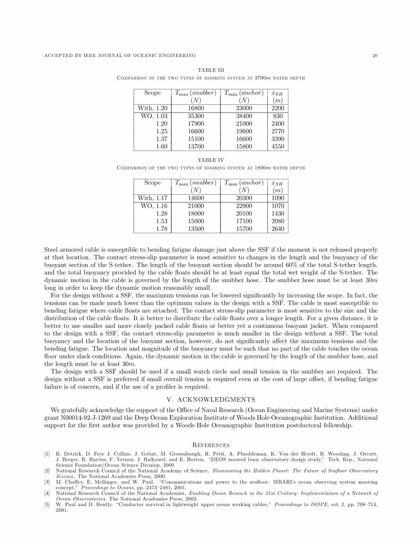
bending fatigue may be an issue.The same analysis is performed for the mooring in 1800m, and the results are shown in Table IV. For the same scope,
the maximum tensions in the design with a SSF are significantly lower than those in the design without a SSF. However,the maximum tensions in the design without a SSF can, again, be lowered significantly with increasing scope.The design without a SSF provides a long, smooth section of cable without the interruptions of cable floats or
subsurface buoys. This is a clear design advantage if the mooring is to be used with a near-surface profiler that movesup and down the cable in the upper water column.In summary, the design with a SSF can be optimized for maximum tensions by choosing an appropriate S-tether
length. In this case, the maximum snubber tension and the horizontal offset are smaller than those of the design withouta SSF with the same scope under survival conditions. However, the maximum tensions in the design without a SSF canbe lowered by increasing the scope of the mooring. The design without a SSF is also subject to smaller bending fatigueand has an advantage when a near-surface profiler is required.
IV. CONCLUSION
For the design with a SSF, the most important design parameter in terms of the maximum tensions is the lengthof the S-tether. The optimal length of the S-tether under survival conditions depends on the depth of the subsurfacebuoy. If the subsurface buoy is placed too shallow, the optimal length may be impractical under the slack condition.
ACCEPTED BY IEEE JOURNAL OF OCEANIC ENGINEERING 20
TABLE III
C������� �� �� ��� ��� � �� ������ ���� � � 3700m �� � � ���
Scope Tmax (snubber) Tmax (anchor) xSB(N) (N) (m)
With, 1.20 16800 23000 2200WO, 1.03 35300 38400 830
1.20 17900 21000 24001.25 16600 19600 27701.37 15100 16600 33901.60 13700 15800 4550
TABLE IV
C������� �� �� ��� ��� � �� ������ ���� � � 1800m �� � � ���
Scope Tmax (snubber) Tmax (anchor) xSB(N) (N) (m)
With, 1.17 14600 20300 1090WO, 1.16 21000 22900 1070
1.28 18000 20100 14301.53 15000 17100 20801.78 13500 15700 2640
Steel armored cable is susceptible to bending fatigue damage just above the SSF if the moment is not released properlyat that location. The contact stress-slip parameter is most sensitive to changes in the length and the buoyancy of thebuoyant section of the S-tether. The length of the buoyant section should be around 60% of the total S-tether length,and the total buoyancy provided by the cable floats should be at least equal the total wet weight of the S-tether. Thedynamic motion in the cable is governed by the length of the snubber hose. The snubber hose must be at least 30mlong in order to keep the dynamic motion reasonably small.For the design without a SSF, the maximum tensions can be lowered significantly by increasing the scope. In fact, the
tensions can be made much lower than the optimum values in the design with a SSF. The cable is most susceptible tobending fatigue where cable floats are attached. The contact stress-slip parameter is most sensitive to the size and thedistribution of the cable floats. It is better to distribute the cable floats over a longer length. For a given distance, it isbetter to use smaller and more closely packed cable floats or better yet a continuous buoyant jacket. When comparedto the design with a SSF, the contact stress-slip parameter is much smaller in the design without a SSF. The totalbuoyancy and the location of the buoyant section, however, do not significantly affect the maximum tensions and thebending fatigue. The location and magnitude of the buoyancy must be such that no part of the cable touches the oceanfloor under slack conditions. Again, the dynamic motion in the cable is governed by the length of the snubber hose, andthe length must be at least 30m.The design with a SSF should be used if a small watch circle and small tension in the snubber are required. The
design without a SSF is preferred if small overall tension is required even at the cost of large offset, if bending fatiguefailure is of concern, and if the use of a profiler is required.
V. ACKNOWLEDGMENTS
We gratefully acknowledge the support of the Office of Naval Research (Ocean Engineering and Marine Systems) undergrant N00014-92-J-1269 and the Deep Ocean Exploration Institute of Woods Hole Oceanographic Institution. Additionalsupport for the first author was provided by a Woods Hole Oceanographic Institution postdoctoral fellowship.
R � � �� �[1] R. Detrick, D. Frye J. Collins, J. Gobat, M. Grosenbaugh, R. Petit, A. Plueddeman, K. Von der Heydt, B. Wooding, J. Orcutt,
J. Berger, R. Harriss, F. Vernon, J. Halkyard, and E. Horton, “DEOS moored buoy observatory design study,” Tech. Rep., NationalScience Foundation/Ocean Science Division, 2000.
[2] National Research Council of the National Academy of Science, Illuminating the Hidden Planet: The Future of Seafloor ObservatoryScience, The National Academies Press, 2000.
[3] M. Chaffey, E. Mellinger, and W. Paul, “Communications and power to the seafloor: MBARI’s ocean observing system mooringconcept,” Proceedings to Oceans, pp. 2473—2481, 2001.
[4] National Research Council of the National Academies, Enabling Ocean Reseach in the 21st Century: Implementation of a Network ofOcean Observatories, The National Academies Press, 2003.
[5] W. Paul and D. Bently, “Conductor survival in lightweight upper ocean working cables,” Proceedings to ISOPE, vol. 2, pp. 708—714,2001.

ACCEPTED BY IEEE JOURNAL OF OCEANIC ENGINEERING 21
TABLE V
P��� �� � �� �� V ���� ��� �� ����� �
Vectran, steel-armored,armor-covered Vectran cable
EA (MN) 5, 10, 10EI (Nm2) 0.1, 0.5, 0.5GJ (Nm2) 0.5, 1, 1mass/length (kg/m) 0.477, 0.877, 1.042added mass/length (kg/m) 0.426, 0.520, 0.240diameter (m) 0.0230, 0.0254, 0.0285Cdt 0.0, 0.0, 0.0Cdn 1.5, 1.5, 1.5wet weight (N) 0.1, 6.8, 1.345
[6] J.H. Evans and J.C. Adamchak, Ocean Engineering Structurs, The M.I.T. Press, Cambridge, Massachusetts and London, England,1969.
[7] H.O. Berteaux, Buoy Engineering, John Wiley and Sons, New York, 1976.[8] R.H. Canada and D.R. May, “Mooring developments and design philosophy at the National Data Buoy Center,” Proceedings to Oceans,
pp. 1336—1343, 1985.[9] Z.L. Machado and J.M. Dumay, “Dynamic production riser on Enchova field offshore Brazil,” Offshore Brazil Conference, Latin America
Oil Show, 1980, Rio de Janeiro.[10] American Petroleum Institute, Recommended Practice for Flexible Pipe, RP 17B, 2002.[11] F.B. Seyed and M.H. Patel, “Parametric studies of flexible risers,” Proceedings of the First International Offshore and Polar Engineering
Conference, vol. 2, pp. 147—156, 1991.[12] M. Raoof and R. Hobbs, “Analysis of multilayered structural strands,” Journal of Engineering Mechanics, ASCE, vol. 114, no. 7, pp.
1166—1182, 1988.[13] M. Raoof, “Axial fatigue of multilayered strands,” Journal of Engineering Mechanics, vol. 116, no. 10, pp. 2083—2099, 1990.[14] M. Raoof, “Free-bending fatigue of multilayered strands,” Journal of Engineering Mechanics, ASCE, vol. 118, no. 9, pp. 1747—1764,
1992.[15] M. Raoof, “Design of steel cables against free-bending fatigue at terminations,” The Structural Engineer, vol. 71, no. 10, pp. 171—178,
1993.[16] J.I. Gobat and M.A. Grosenbaugh, “WHOI Cable v2.0: Time domain numerical simulation of moored and towed oceanographic systems,”
Tech. Rep. Technical Report WHOI-2000-08, Woods Hole Oceanographic Institution, 2000.[17] J.I. Gobat and M.A. Grosenbaugh, “WHOI Cable: Time domain numerical simulation of moored and towed oceanographic systems,”
Nice, France, 1998, Proceedings of Oceans’98.[18] J.I. Gobat and M.A. Grosenbaugh, “Dynamics in the touchdown region of catenary moorings,” International Journal of Offshore and
Polar Engineering, vol. 11, pp. 273—281, 2001.
A�� ���
I. PROPERTIES OF TWO MOORING SYSTEMS
Configuration for the Mooring System with a SSF• Anchor• 5m potted chain• 2990m Vectran cable• 5m potted chain• 10200N (2300lb) SSF• 5m potted chain• 700m steel armored cable with thirty-six 272N (61lb) cable floats @20m• 700m steel armored cable• 13.35kg coupling• 30m snubber
Configuration for the Mooring System without a SSF• Anchor• 5m potted chain• 1440m Vectran cable• 420m Vectran cable with twenty-two 136N (30.5lb) cable floats @20m• 1925m Vectran cable• 5m potted chain• 800m armored covered Vectran cable• 13.35kg coupling• 30m snubber

ACCEPTED BY IEEE JOURNAL OF OCEANIC ENGINEERING 22
TABLE VI
P��� �� � �� �� C�� F����
SSF 272N Cable floatdiameter (m) 1.54 0.5657mass (kg) 921 35.7added mass (kg) 1909 28.6wet weight (N) −10235 −272Cdt 0.2 0.2Cdn 0.8 1
TABLE VII
P��� �� � �� �� V ���� S����
Layer Number E Wire diameter Lay angleof wires (MPa) (mm) (◦)
1 30 200 3.54 17.742 24 117 3.54 -16.453 18 117 3.54 -15.934 12 117 3.54 14.905 7 117 3.54 15.52king 1 117 5.05
The surface buoy is modeled as a cylinder. The mass is 3200kg, the diameter is 3.2m, height is 1.5m, the surface areaexposed in the air is 6.2m2, the wind drag coefficient is 1.5, and the normal fluid drag coefficients is 1.