Embed Size (px)
Citation preview

ELECTRONICS, VOL. 25, NO. 1, JUNE 202120
Abstract—Decimal digit number computation, through bit compression methodology, offers space and time saving, which can be incurred by the Chen-Ho and Densely Packed Decimal (DPD) coding techniques. Such coding techniques have a property of bit compression, like, three decimal digits can be represented by 10 bits instead of 12 bits in binary coded decimal (BCD) format. The compression has been obtained through the elimination of the re-dundant 0’s from BCD representation. This manuscript reports the pros and cons of the techniques mentioned above. The logic lev-el functionalities have been examined through MATLAB, where-as circuit simulation has been verified through Cadence Spectre. Performance parameters (such as delay, power consumption) have been evaluated through CMOS gpdk45 nm technology. Further-more, the best design has been chosen from them, and the decimal adder design technique has been incorporated in this paper.
Index Terms—Chen-Ho coding, DPDcoding, Power, Delay, Decimaladder.
Original Research PaperDOI: 10.53314/ELS2125020B
I. Introduction
Decimal arithmetic has been highly emphasized lately due to the increasing role of commercial, financial, and inter-
net-based applications. The human interpretation of numbers in the decimal system is considerably more accessible than the binary system. Therefore, a decimal-based implementation ap-proaches like fractions becomes more relevant from its count-er-part, i.e., the binary system, which incurs recurring infinity bits [1]. Thereby, it is expected that inputs and outputs of the
decimal notation from the machine also need to be decimal. The cost of hardware, which is the paramount concern for the digital arena, is increased due to its conversion, programming, and troubleshooting. Consequently, it seems more logical to im-plement decimal arithmetic in machines instead of forcing users to think in binary mode [2].
Decimal to binary conversion and vice versa is the prime requirement while adding two decimal numbers using binary adders. Meanwhile, the hardware required for this purpose increases with an increase in the decimal number value. This increase in hardware is the continuous division (Double dabble method) and multiplication operations performed in decimal to binary and binary to decimal conversions. Furthermore, the conversion of fractional decimal numbers into binary causes recurring infinity bits. Thereby, the converted decimal fraction number becomes incorrect and causes approximate errors [17]. Moreover, it affects the overall speed of operation of the addi-tion process.
For decimal computation, each digit individually can be represented in binary coded decimal (BCD), and each of them can also be represented into four binary bits. Also, the same can be expressed compactly, like Chen–Ho [2] and Densely Packed Decimal (DPD) [1] coding,which are more lucrative in certain circumstances.
In 1975 Chen and Ho proposed an effective encoding tech-nique (Chen-Ho encoding) to represent decimal data [2], which usually compresses three decimal digits into 10 bits rather than 12 bits. By considering the Huffman Code [3], various digit combinations have been formed using leading indicator bits. The Huffman code helps to determine the smaller (0 to 7) and larger (8, 9) digits present in a multi-digit decimal number. Fur-thermore, Chen–Ho encoding gives 17% more compact encod-ing than BCD with little waste. Simple Boolean operations are used for conversion or re-conversion. Floating-point decimal numbers can also be encoded in binary register using Chen-Ho encoding [4].
Another coding technique, namely DPD methodology [1], permits subjective length decimal numbers to be coded effi-ciently. DPD also performs compression of the three decimal digits into 10-bit instead of 12. This coding technique has also been based on Huffman coding, similar to the previously men-tioned Chen–Ho encoding. Analogous to BCD encoding, DPD encoding allows all smaller and larger bits to be right-aligned. In contrast, Chen-Ho encoding follows the BCD pattern only
On The Implementation of Densely Packed Decimal Number System based Adder:
Prospects and ChallengesSrikant Kumar Beura, Rekib Uddin Ahmed, Bishnulatpam Pushpa Devi, and Prabir Saha
Manuscript received 19 November 2020. Received in revised form 22 March and 11 May 2021. Accepted for publication 31 May 2021.
Srikant Kumar Beura is with the Department of Electronics and Commu-nication Engineering, National Institute of Technology Meghalaya, Shillong 793003, India.(email: [email protected])
Rekib Uddin Ahmed is with the Department of Electronics and Commu-nication Engineering, National Institute of Technology Meghalaya, Shillong 793003, India. (email: [email protected])
Bishnulatpam Pushpa Devi is with the Department of Electronics and Communication Engineering, National Institute of Technology Meghalaya, Shillong 793003, India.(email: [email protected])
Prabir Saha is with the Department of Electronics and Communication En-gineering, National Institute of Technology Meghalaya, Shillong 793003, India (corresponding author: +91-364-2501294; fax: +91-364-2501113; e-mail: [email protected]).

ELECTRONICS, VOL. 25, NO. 1, JUNE 2021 21
for smaller digits (0 to 7), whereas for higher digits (8,9), it gives more weightage to the MSB. On the otherhand, the Chen-Ho algorithm requires completely different coding for single, double, and three decimal digits. However, the same algorithm is applicable for DPD to represent single, double, and three dec-imal digits with zero paddings on the left side only.
Moreover, computational circuitry, like the addition of decimal numbers, non-speculative adder takes less delay and consume nearly the same space than speculative adders [5]. A different non-speculative adder has been proposed by Lin et al. [6], where binary carry-save adder (CSA) is used on BCD input along with a correction module. Svoboda [7] has proposed a signed digit decimal adder considering the digit set [-6, 6]. In [7], each decimal digit (x) is multiplied by 3, and the multipli-cation result is stored in 5-bits, where significant overhead is required for the signed digit code conversion. Furthermore, re-searchers have proposed several decimal adders with precision in various literatures [8]–[14]. The adders offered by Bohlender et al. [9] and Cohen et al. [10] have quite long latencies while producing each result. A speculative signed-digit adder was proposed by Moskal et al. [12], where both the input operands are represented as sign-digit numbers.The operand is selected as apositive 4-bit vector and anegative 4-bit vector. The imple-mentation technique is good enough with the penalty of algo-rithmic complexity. In [13]-[14], researchers have proposed an adder/subtractor module for signed magnitude format, with the scarification of other two significant VLSI aspects, i.e., delay and power consumption.
In this paper, the design technique of Chen-Ho and DPD coding has been addressed as a function of bit-positioning. Both coding techniques were simulated in MATLAB to analyze each code’s bit-positioning and, later on, simulated in Cadence Spectre to compare the delay and average power consumption. Furthermore, a 3-digit decimal adder using the DPD coding technique has been proposed in this paper. The proposed deci-mal adder is compared with the existing designs [13]-[14], [16]-[17] as a function of the VLSI performance parameters such as delay and average power using gpdk45 nm technology. For the validation of the proposed decimal adder’s exactness, image addition has been carried out and compared.
The manuscript is organized as follows: Section II provid-ing pieces of information about some existing designs; Section III gives the brief logic behind the design of both the coding techniques; Section IV shows the comparative analysis of both the coding techniques as a function of power and delay; Section V demonstrates the implementation of the proposed DPD based decimal adder; Section VI shows the observations between pro-posed and existing adders; Section VII belongs to the applica-tion: image addition, followed by the conclusion (Section VII).
II. Related Work
In digital systems, the decimal numbers are usually encod-ed in BCD for arithmetic operations. The BCD adder takes two BCD digits as an input and provides the addition result, which is also in BCD [15].
The architecture of the conventional BCD adder has been shown in Fig. 1. There are two decimal digits, namely Aand B. The addition operation has been performed using binary ad-ders, e.g., ripple carry adder (RCA) or carry look-ahead adder (CLA). The summation result has to pass through another stage where the correction needs to be completed. The intermediate summation result is denoted by S3,S2,S1,and S0. The Carry-out and final summation result (Sum3-Sum0) have been generated by adding ‘0110’ to the intermediate summation result.
From Fig. 1, it has been observed that the delay of reported architecture is directly proportional to the digit width of dec-imal input. There are a few short-comings of the BCD adder, which are summarized below.
• For the generation of early carry, the BCD adder needs extra circuits. Moreover, ~20% more circuitry is required for the BCD addition than conventional binary addition.
• Usually, BCD representation (4-bits per digit) of decimal digits increases the storage space by ~20% than the stan-dard binary encoding, which results in storage overhead.
• It has been observed that, in any operation, the practical implementation of BCD is much slower than the binary representation.
Fig. 1. 1-digit BCD adder [15]
In [16], the authors have proposed a fast BCD addition method known as fast decimal adders. The fast decimal ad-der’s architecture also consists of three stages which is shown in Fig. 2. This adds two decimal numbers having three-digit each. Therefore, in binary, the inputs are A[11:0], B[11:0], and the Cin. In stage 1, both decimal digits are (each represented by 12-bits in binary) added together using CLA to obtain binary Sum[11:0] along with generate and propagate signals. DPi is the digit propagate signal, whereas DGi is the Digit Generate signal. DPi and DGi have been used to check whether the bi-nary sums are equal to 9 and bigger than 9, respectively. The boolean expressions to represent DPi and DGi are provided

ELECTRONICS, VOL. 25, NO. 1, JUNE 202122
in eqn. (2), (3). In stage 2, in order to calculate the real deci-mal carries Carry[i] (as shown in eqn. 1), DPi and DGi signals have been considered as an input to the Carry network, which is made up of a parallel-prefix computation unit. Lastly, in stage 3, the summation of the correction values and the binary sums produced by stage 1 has been carried out to generate the final summation result [12:0].
Carry[i] = DGi + DPi˙ Carry[i - 1] (1)
DGi = Cout + (S[i + 3].(S[i + 2]+ S[i + 1] ) ) (2)
DPi = S[i + 3] .S[i + 1]) (3)
Fig. 2. Reduced delay BCD adder [16]
Researchers in [17] have proposed a similar decimal adder as in [16] with some significant modifications. This decimal adder [17] has been adding three decimal numbers of 4-digit each simultaneously. In stage1, binary converted decimal digits are fed to the CSA+PG unit. This CSA+PG unit is generating DPi and DGi signals along with Sum and Carry outputs. The decimal carries are computed in the 2nd stage with the help of carry network. The sums are calculated in the last stage by using carry-save adders (CSA) plus 4-bit carry-lookahead ad-ders (CLA) which are adding the digit sums and carries with correction values.
Fig. 3. Area Efficient Decimal Adder [17]
III. Description of Chen-Ho and DPD Coding Techniques
A. Chen-Ho EncodingBCD encoding technique required four bits to represent each
decimal digit. For example, if A is denoted as a single-digit deci-mal number, then the four-bits are needed to represent Ain BCD, i.e., abcd, such that A= 8a + 4b + 2c + d. Similarly, two decimal digits A,B can be represented as abcd efgh and three decimal digits A,B,C can be described as abcd efgh ijkl and so on.
The representation of each decimal digit as 4-bits conserve extra space, as four bits indicate 16 states (0 to 15),preferably 10 (0 to 9). Thereby, the relative inefficiency of BCD encoding with the help of binary notation (r) [2], i.e., r = 4 log 2/log 10 = 1.204. Therefore, the binary representation is saving 20.4% of space as compared to BCD.
To represent small decimal digits (0-7) in BCD format re-quires 4-bits (abcd), whereas these can be expressed in 3-bit (bcd) only. For the encoding of larger digits (8, 9), BCD needs four digits (abcd). However, for larger digits, a is always logic ‘1’ and d is logic ‘0’ for 8 and logic ‘1’ for 9. Furthermore, bc is still the logic ‘0’ for larger digits. Therefore, in Chen-Ho encoding, bc has been omitted for larger digits. By merely discarding the repetitive 0 bits in a BCD message, a consolidated code is obtained.
Chen-Ho proposed an efficient encoding by using the ‘indi-cator field’ and ‘detailed field’. The role of this indicator bit is to specify the occurrence and the position of the larger digit. In combination with the indicator bit, the detailed field gives the larger decimal digit’s actual value.
The 3-digit decimal number mapping issue can be resolved with Huffman encoding [3], which has been used in Chen-Ho encoding. The 3-digit decimal number in BCD is represented by 12 bits (abcd efgh ijkl). Three bits, namely (a,e,i), have been used as indicator bits. Therefore four cases may arise depend-ing upon the smaller (0 to 7) and larger (8,9) bit combination, which are provided in Table I.
Table ILogic Used for Chen-Ho Encoding
Case 1 When all 3-digits decimal numbers are small (0-7), the possibil-ity of occurrence is 51.2%, encoded by (0).
Case 2 If any 1-digit decimal number is large (8,9), then the possibility of occurrence is 38.4%, encoded by (100, 101, 110).
Case 3 If 2-digits decimal numbers are large, then the possibility of occurrence is 9.6%, encoded by (11100, 11101, 11110)
Case 4 If all three decimal digits are large, then the possibility of occur-rence is 0.8%, encoded by (11111).
The representation of 3-digit decimal numbers (abcd efgh
ijkl) in the 10-bit binary was given (pqrstuvwxy). From the re-sulting bits (pqrstuvwxy), (s,v,y) is always standing with (d,h,l) of the BCD digits. Table II shows the compression of 3-digit decimal numbers into 10-bit.
Furthermore, Chen-Ho demonstrated that no arithmetic operation had been implemented; instead, only shift, deletion, and insertion is used. The Boolean algebra used for encoding of 12-bit into 10-bit binary and decoding is provided in Tables III and IV.
ELECTRONICS, VOL. 25, NO. 1, JUNE 2021 23
Table II The Compression Algorithm of 12-bits Into 10-Bits (Chen-Ho)
a e i p q r s t u v w x y
0 0 0 0 b c d f g h j k l
1 0 0 1 0 0 d f g h j k l
0 1 0 1 0 1 d b c h j k l
0 0 1 1 1 0 d f g h b c l
0 1 1 1 1 1 d 0 0 h b c l
1 0 1 1 1 1 d 0 1 h f g l
1 1 0 1 1 1 d 1 0 h j k l
1 1 1 1 1 1 d 1 1 h 0 0 l
Table IIIBoolean Algebra for The Compression of 12-Bits Into 10-Bits
Compression into 10 Bits
p a + e + i
q b ē + i + a e
r ci̅ + e + ai
s d
t ae + f (a + ī ) + beī
u ai+ge̅+cei̅
v h
w j+bi+fai
x k+ci+gai
y l
Table IVBoolean Algebra for The Expansion of 10-Bits into 12-bits
Expansion into 12 Bits
a pq̅r̅ + pqr(t + u)
b qp̅ + tpq̅r + wq(r̅ + t̅u̅)
c r(p̅+q̅u) + xpq(r̅ + t̅u̅)
d s
e pr(q̅ + u̅ + t)
f t(p̅ + r̅ ) + pqrt̅uw
g u(p̅ + r̅ ) + pqrt̅ux
h v
i pq(r̅ + t̅ + u)
j w(p̅ + q̅ + rt)
k x(p̅ + q̅ + rt)
l y
B. Improvement on Chen-Ho EncodingThe Chen-Ho encoding works effectively when it deals with
a 3-digit decimal number. Meanwhile, if the number of deci-mal digits is other than 3-digit (either one or two-digit), then Chen-Ho encoding does not work; hence this encoding needs to be redesigned. These are some points that need improvement in Chen-Ho encoding:
1. Chen–Ho encoding requires different coding techniques for 2-digits and 3-digits fields.
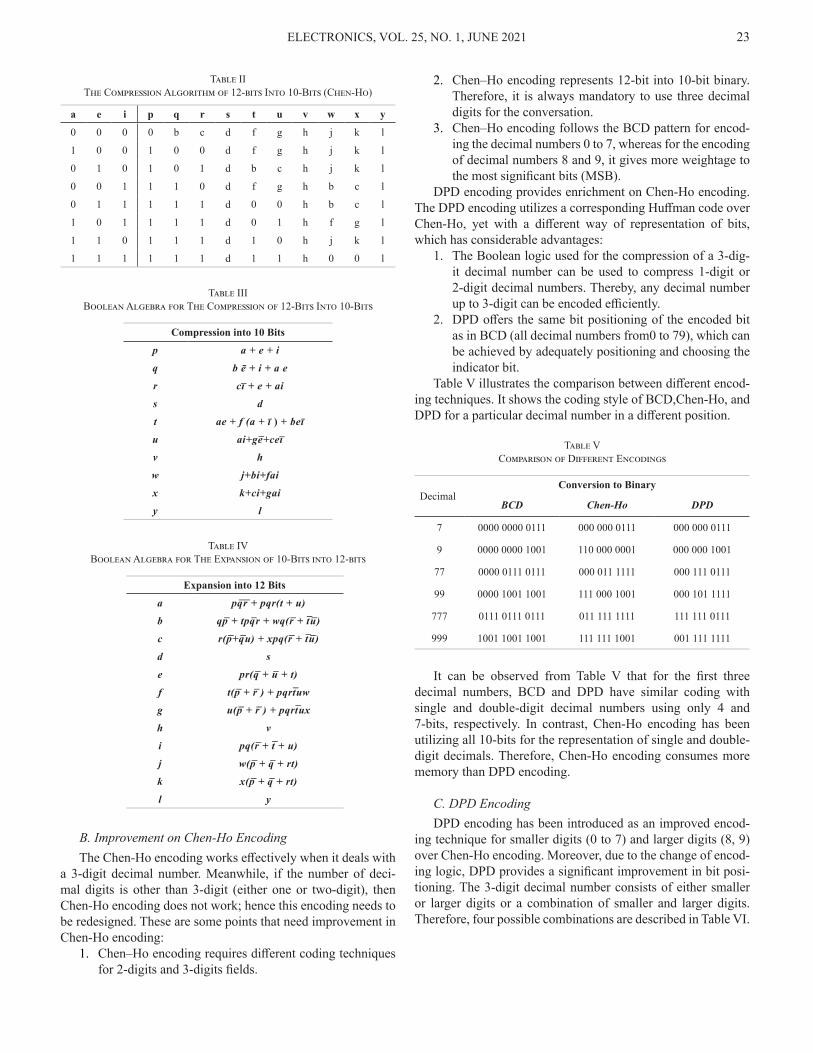
2. Chen–Ho encoding represents 12-bit into 10-bit binary. Therefore, it is always mandatory to use three decimal digits for the conversation.
3. Chen–Ho encoding follows the BCD pattern for encod-ing the decimal numbers 0 to 7, whereas for the encoding of decimal numbers 8 and 9, it gives more weightage to the most significant bits (MSB).
DPD encoding provides enrichment on Chen-Ho encoding. The DPD encoding utilizes a corresponding Huffman code over Chen-Ho, yet with a different way of representation of bits, which has considerable advantages:
1. The Boolean logic used for the compression of a 3-dig-it decimal number can be used to compress 1-digit or 2-digit decimal numbers. Thereby, any decimal number up to 3-digit can be encoded efficiently.
2. DPD offers the same bit positioning of the encoded bit as in BCD (all decimal numbers from0 to 79), which can be achieved by adequately positioning and choosing the indicator bit.
Table V illustrates the comparison between different encod-ing techniques. It shows the coding style of BCD,Chen-Ho, and DPD for a particular decimal number in a different position.
Table VComparison of Different Encodings
DecimalConversion to Binary
BCD Chen-Ho DPD
7 0000 0000 0111 000 000 0111 000 000 0111
9 0000 0000 1001 110 000 0001 000 000 1001
77 0000 0111 0111 000 011 1111 000 111 0111
99 0000 1001 1001 111 000 1001 000 101 1111
777 0111 0111 0111 011 111 1111 111 111 0111
999 1001 1001 1001 111 111 1001 001 111 1111
It can be observed from Table V that for the first three decimal numbers, BCD and DPD have similar coding with single and double-digit decimal numbers using only 4 and 7-bits, respectively. In contrast, Chen-Ho encoding has been utilizing all 10-bits for the representation of single and double-digit decimals. Therefore, Chen-Ho encoding consumes more memory than DPD encoding.
C. DPD EncodingDPD encoding has been introduced as an improved encod-
ing technique for smaller digits (0 to 7) and larger digits (8, 9) over Chen-Ho encoding. Moreover, due to the change of encod-ing logic, DPD provides a significant improvement in bit posi-tioning. The 3-digit decimal number consists of either smaller or larger digits or a combination of smaller and larger digits. Therefore, four possible combinations are described in Table VI.

ELECTRONICS, VOL. 25, NO. 1, JUNE 202124
Table VILogic Used for DPD Encoding
Case 1Let all 3-digits are smallIt requires 9-bits to represent three decimal digits, leaving 1-bit as an indicator bit.
Case 2
Let anyone digit is largeIt needs 7-bits to represent three decimal digits, leaving 3-bits for the indication (to know the larger digit’s exact value and position-ing).
Case 3Let any two digits are largeNow 5-bits needed for three-digit decimal representation, leaving 5-bits for indication.
Case 4Let all three digits are large Finally, 3-bits are required for three-digit decimal number repre-sentation, leaving 7 bits for indication, whereas 5-bits are enough.
a. Compression of 3-digit decimal (12 bits) into 10 bits us-ing DPD:
The compression of a 3-digit decimal number (abcd efgh ijkm) into 10 bit (pqr stu v wx y) can be done using the mapping technique, as depicted in Table VII.
Table VIICompression of 3-Digit Decimal Number (12-Bits) Into DPD (10 Bits)
a e i p q r s t u v w x y
0 0 0 b c d f g h 0 j k m
0 0 1 b c d f g h 1 0 0 m
0 1 0 b c d j k h 1 0 1 m
0 1 1 b c d 1 0 h 1 1 1 m
1 0 0 j k d f g h 1 1 0 m
1 0 1 f g d 0 1 h 1 1 1 m
1 1 0 j k d 0 0 h 1 1 1 m
1 1 1 0 0 d 1 1 h 1 1 1 m
In this compression algorithm, ‘v’ has been regarded as the indicator bit. If the 3-digit decimal number contains at least one larger number (8, 9), then ‘v’ is considered 1, and if the three-digit decimal number contains only smaller numbers (0-7), then ‘v’ is denoted by 0. For example, if the 3-digit decimal number is 786, it will be represented as 0111 1000 0110. Now the value of a=0, e=1, and i=0. Therefore, it will follow the com-pression technique, as shown in the fourth row of Table VII. The value of ‘v’ is now 1, and w, x is denoted by 0 and 1, respective-ly. The remaining 7-bits are mapped from the input bit pattern by following Table V, and the resulting compressed encoding is given by 111 110 1010.
b. Expansion of 10 bits into 3-digit decimal (12 bits) using DPD:
This operation needs to be performed on the 10-bit (pqr stu v wx y) to get 12-bit (abcd efgh ijkl). The indicator bits used for the expansion are vwxst. Indicator bit (v) plays a vital role in the encoding operation—the asterisk mark (*) denotes don’t care condition.
Table VIIIThe Expansion of 10-bit DPD into 3-Digit Decimal (12-bits)
v w x s t a b c d e F g h i j k m
0 * * * * 0 p q r 0 s t u 0 w x y
1 0 0 * * 0 p q r 0 s t u 1 0 0 y
1 0 1 * * 0 p q r 1 0 0 u 0 s t y
1 1 0 * * 1 0 0 r 0 s t U 0 p q y
1 1 1 0 0 1 0 0 r 1 0 0 U 0 p q y
1 1 1 0 1 1 0 0 r 0 p q U 1 0 0 y
1 1 1 1 0 0 p q r 1 0 0 U 1 0 0 y
1 1 1 1 1 1 0 0 r 1 0 0 U 1 0 0 y
c. Boolean logic used for DPD encoding and decoding The logic used for the DPD encoding and decoding can be
implemented in hardware using Boolean expressions. The ex-pressions provided in Table IX and X which, have been derived from Table VII and VIII, respectively.
Table IXBoolean Expressions for 12-Bit to 10-Bit in DPD
DPD Bits Boolean Expressions for Compression into 10 Bits
p ba̅ + jai̅ + fae̅i
q ca̅ + kai̅ + gae̅i
r d
s fe̅(āi̅ ) + j(a̅ei̅ ) + ei
t ge̅(āi̅) + k(a̅ei̅ ) + ai
u h
v a + e + i
w a + ei + je̅ i̅
x e + ai + ka̅ i̅
y m
Table XBoolean Expressions for 10-Bit to 12-Bit in DPD
BCD Bits Boolean Expressions for Expansion into 12 Bits
a (vw)(x̅ + s̅ + (st))
b p(v̅ + w̅ + (xst̅))
c q(v̅ + w̅ + (xst̅))
d r
e v(w̅x + (wx( s + t̅ ))
f (s (v̅ + (vx̅))) + pvwxs̅t
g (t (v̅ + (vx̅)))+qvwxs̅t
h u
i v((w̅x̅) + wx(s + t))
j wv̅ + svw̅x + (pvw(x̅ + ( s̅ t̅ )))
k xv̅ + tvw̅x + (qvw(x̅ + ( s̅ t̅ )))
m y

ELECTRONICS, VOL. 25, NO. 1, JUNE 2021 25
IV. Comparative Analysis of Chen-Ho and DPD Coding Techniques
The gate-level design of Chen-Ho [2] and DPD [1] coding techniques have been implemented in MATLAB to analyze bit positioning. Furthermore, for the circuit design prospect, the coding techniques mentioned above have been implemented in Cadence Spectre to evaluate the circuit parameters like average power and delay, using gpdk45 nm technology.
Fig. 4 shows a comparison between Chen-Ho and DPD en-codings. In this analysis, 0 to 999 decimal numbers (in 12-bit) have been encoded into 10-bit Chen-Ho and DPD. The 10-bit encoded binary has been converted to a decimal using eqn. 4. This gives an idea of how these two encodings are different from each other.
P = ∑n(i=0)2
ibi (4)
0 200 400 600 800 1000
0
200
400
600
800
1000
1200
Corr
espo
ndin
g De
cimal
Val
ues
Number of points considered for analysis
ChenHo DPD
Fig. 4. Representation of DPD and Chen-Ho encoding in decimal
Where b0,b1,b2… are the binary bits and b0 is the least signifi-cant bit (LSB) starting from the right side, P is the corresponding decimal number.
In Fig. 4, the decimal equivalent of 10-bit Chen-Ho encod-ing is represented by green color, whereas DPD encoding is marked by red color. The decimal equivalent of both encodings is not providing similar results. The decimal equivalent of 10-bit DPD followed the BCD pattern for ~70%, making DPD a better choice to implement a decimal adder over Chen-Ho.
Meanwhile, in BCD addition, when two numbers are add-ed, and the sum exceeds 9, then 6 is added with the summation result to bring it back into BCD. Meanwhile, in DPD encoding, the encoded decimal numbers followed an excellent pattern in most cases. For example, decimal numbers 0 to 9 are encoded in DPD, and their equivalent binary conversion results in 0000 to 1001. Meanwhile, 10 to 19 are encoded as 10000 to 11001. Sim-ilarly, 20 to 29 are encoded as 100000 to 101001 and so on till 79. In this context, it can be observed that the decimal value of the encoded 10-bit DPD shows an increase of 6 for each decade. However, when a larger digit (8 or 9) is present in the 10th or 100th position in the 3-digit decimal number, then the observa-tion mentioned above does not work. It has been observed that the decimal numbers having larger digits in the 10th or 100th place show arbitrary decimal equivalent values of the encoded DPD. When it comes to Chen-Ho encoding, the scenario gets
changed completely. Therefore, DPD can be a better choice over Chen-Ho for the implementation of a decimal adder.
In Table V, the equivalent value of the decimal digit 9 for both Chen-Ho and DPD has been shown. Also, from Fig. 1, it is observed that unlike the DPD encoding, which offers more deviation when it represents larger decimal numbers (i.e., more than 778), the Chen-Ho encoding shows more variation when it corresponds to a smaller decimal number (i.e., less than 778). The reason is, Chen-Ho encoding utilizes logic ‘1’ in higher bits (MSBs) for the representation of larger decimal digits (8 and 9), and the decimal conversion of Chen-Ho encoded numbers are much more extensive compared to its actual decimal equivalent. Meanwhile, DPD encoding utilizes lower bits (LSBs) to repre-sent large decimal digits with minimal error. Therefore, DPD based decimal adder will provide a better result than the Chen-Ho-based decimal adder.
Furthermore, the power and delay analysis of the Chen-Ho and DPD encoder and decoder have been performed in Cadence Spectre using gpdk45 nm technology. The results are provided in Table XI.
Table XIPower and Delay Comparison of Chen-Ho and DPD Encoding and
Decoding
Coding Techniques
Encoding Delay
Decoding Delay
Encoding Power
Decoding Power
Chen-Ho 0.1229ns 0.1034ns 1.401mW 3.238mW
DPD 0.0897ns 0.0815ns 1.101mW 2.752mW
Table XI shows that DPD has been dissipating less power and consuming less delay over Chen-Ho encoding and decod-ing.
These advantages make the DPD encoding a much better option over Chen–Ho encoding for both hardware and software representations of decimal numbers and decimal adder imple-mentation.
V. Implementation of Decimal Adder Using Densely Packed Decimal Coding
BCD adder has some limitations while adding two 3-digit decimal numbers. In order to overcome these limitations, a new methodology has been proposed. This methodology will not only reduce the computational storage requirements but also will speed up the addition process. In addition to the decimal to binary and binary to decimal converter, the proposed DPD-based decimal adder consists of three stages, as shown in Fig. 5.
The decimal to binary converter converts each decimal digit into four binary bits. Therefore, a 3-digit decimal number gets converted into 12-bits binary.
Stage-1: The 12-bits binary (a to m) data is given as input to the DPD encoder, which compresses it to 10-bit data (p to y). In the proposed design, two DPD encoders are used, namely D1 and D2. Both D1 and D2 simultaneously encode 12-bit binary data to 10-bit binary each. These 10-bit outputs are p1 to y1 and p2 to y2 for D1 and D2, respectively.

ELECTRONICS, VOL. 25, NO. 1, JUNE 202126
Fig. 5. Proposed DPD based Decimal Adder
Stage-2: In this stage, both the 10-bit DPD encoded num-bers, namely p1 to y1 and p2 to y2, are added using CLA-1. Thus summation result (pi to yi) is obtained. This summation result needs correction only when it satisfies the eqn. 5. It can be observed from Table VII that the indicator bits (vi,wi,xi,yi) give an idea about the larger digit’s (8,9) occurrence and value. In CLA-2, The summation result of CLA-1 has been added with the correction value to get the final sum.
Corr = (vi . wi ) + (xi + yi ) (5)
Stage-3: In order to get the final summation result in deci-mal, the output generated by CLA-2 needs to be converted in the form of a 12-bit binary. Therefore, a DPD decoder circuit is employed. It takes 10-bits as input and provides 12-bit as output (as mentioned in Table X).
VI. Observations and Challenges
The numerical analysis of the existing decimal adder [17] with the proposed one has been shown in Fig. 6. The existing decimal adder’s algorithm adds three 4-digit decimal numbers in three stages. In this addition process, initially, adder and analyzer circuit gennnerates Sum S[i], Carry C[i], DGi and DPi signals. Furthermore, the carry network will calculate correc-tion (Corr) signal using DGi and DPi signals. In the last step, all three signals, i.e., Sum S[i], Carry C[i], and correction (Corr) signals, are added together to get the final sum.
However, in the proposed DPD based decimal adder, a con-version of 12-bits to 10-bits is performed before the addition. Then correction operation has been performed. Subsequently, the final sum is obtained by again converting the 10-bit binary to the 12-bit binary. Hence, the proposed DPD based decimal adder utilizes substantially fewer steps for the addition than the
Fig. 6. Numerical based comparison of existing [17] and proposed decimal adder

ELECTRONICS, VOL. 25, NO. 1, JUNE 2021 27
reported decimal adder [17], thereby reducing the computation-al time with less power dissipation.
In this process of adding two decimal numbers, the deci-mal numbers should be converted to binary for carrying out the addition operation. After the completion of the addition pro-cess, the results in binary should be converted back to decimal. Along with all the existing decimal adders [13]-[14], [16]-[17]financial and internet based applications. In this paper a new architecture for efficient Binary coded decimal (BCD, the pro-posed DPD based decimal adder follow the same procedure. Therefore, the hardware architecture used in the proposed dec-imal adder is similar to the existing decimal adders. Further-more, the simulation result for the decimal to binary conversion and binary to decimal conversion has been calculated in Ca-dence Spectre and provided in Table XII.
Table XIIPower and Delay Comparison of Decimal to Binary and Binary to
Decimal Conversion Modules
Parameters Decimal to Binary Binary to Decimal
Power (mW) 0.878 0.667
Delay (ns) 0.0313 0.0222
Circuit level implementation of the proposed DPD based
decimal adder and the reported adders [13]-[14]financial and internet based applications. In this paper a new architecture for efficient Binary coded decimal (BCD has been implemented in Cadence Spectre. The performance parameters like power and delay have been extracted in Cadence Spectre using gpdk45 nm technology. All the possible outputs for the decimal numbers’ input combinations between 0 to 999 have been observed.
Proposed Kumar [13] Calderon [14] Alp [16] Tso [17]0
4
8
12
16
20
Ave
rage
Pow
er (m
W)
Proposed and Existing Decimal Adder Designs
Fig. 7. Average Power of the Proposed and Existing Decimal Adders
Analysis of average power consumption is shown in Fig. 7. The existing decimal adder design [17] is consuming more power, followed by [16]-[13]-[14]. In contrast, the proposed decimal adder is consuming less power as compared withall ex-isting reported architectures.
Proposed Kumar [13] Calderon [14] Alp [16] Tso [17]0
1
2
3
4
5
Del
ay (n
s)
Proposed and Existing Decimal Adder Designs
Fig. 8. Delay of the Proposed and Existing Decimal Adders
In Fig. 8, it has been observed that the proposed decimal adder produces the least delay in comparison to the existing adders [13]-[14], [16]-[17].
Proposed Existing [13]Existing [14] Alp [16] Tso [17]0
10
20
30
40
50
60
70Po
wer
Del
ay P
rodu
ct(p
J)
Proposed and Existing Decimal Adder Designs
Fig. 9. PDP of the Proposed and Existing Decimal Adders
Fig. 9 shows the power delay product analysis of the exist-ing and the proposed decimal adders. It is concluded that the proposed decimal adder offers substantially improved perfor-mance parameters than its counter-parts [13]-[14], [16]-[17].
Comparison of BCD and Binary based Decimal AdderAddition of two decimal numbers using binary adders, both
the decimal digits have to convert into binary. Therefore, the double-dable method (division by 2) is used [17], where each decimal digit is successively divided by 2. The remainders gen-erated in each step are considered together as the correspond-ing binary equivalent. However, in BCD, each decimal digit is represented by 4-bits using 8421 encodings. For example, consider a decimal digit 997 whose BCD representation is 1001 1001 0111, whereas its binary representation is 1111100101. In

ELECTRONICS, VOL. 25, NO. 1, JUNE 202128
this conversion, since the encoding is carried out in parallel, only one encoder delay have to consider. However, due to the successive division of the decimal number by 2, the size of the encoder circuit and delay increases significantly in decimal to binary conversion. Moreover, the encoder size and propagation delay are proportionally increasing with the size of decimal number. On the other hand, the addition operation is performed using carry propagate adder (CLA/RCA) in both the bina-ry-based decimal adder and BCD-based decimal adders. How-ever, the BCD-based decimal adder requires extra circuitry for correction.
The corresponding summation result is in binary, and this needs to get converted back to decimal. With the help of eqn. 4, binary to decimal conversion is performed. Meanwhile, the BCD-based summation result is grouped into 4-bits starting from LSB and decoded back to decimal. The delay of the binary to decimal conversion depends on the length of the summation result generated, whereas in BCD, it depends upon only one BCD to decimal decoder delay. Although the addition process using binary adders depends upon carry propagate adder only, conversion of decimal to binary and binary to decimal increases the overall delay. In this process of decimal addition using bina-ry adders, the main disadvantage is the conversion of decimal to binary and binary to decimal.
Therefore, to justify, binary adder-based decimal adder has been implemented in Cadence Spectre and the average power and minimum delay has been extracted using gpdk 45nm tech-nology. It’s noteworthy that circuits are evaluated at three dif-ferent stages, and results are provided in Table XIII.
Table XIIIPower and Delay Comparison of Binary and BCD Based Decimal
Adders
Decimal Adder Parameters Decimal to
BinaryCLA/RCA Addition
Binary to Decimal
Using Bina-ry Adders
Power(mW) 2.212 6.02 0.894
Delay(ns) 1.823 0.76 1.132
Using BCD Adders
Power(mW) 0.878 9.67 0.667
Delay(ns) 0.0313 2.88 0.0222
It is observed from Table XIII that the decimal adder based on binary adder shows 22.8% of improvement in overall pow-er dissipation over its counter-part. However, the BCD ad-der-based decimal adder gains 26.6% in delay over the binary adder-based decimal adder.
Furthermore,the conversion of floating-point decimal num-bers into binary causes recurring infinity bits. Thereby, the con-verted decimal fraction number becomes incorrect and causes approximate errors [17]. However, DPD based encoding can convert floating-point decimal numbers in binary registers ef-ficiently without any loss [1]. Therefore, BCD adder-based decimal adders are preferred as a better choice while making decimal adder over binary adder-based decimal adder.
A. Challenges associated with Decimal adder using DPD Coding TechniqueThe addition of two decimal numbers using DPD encoding
has not given correct results for all possible additions. The ad-dition of two three-digit decimal numbers is offering 84.44% correct outputs. The reason is, while adding two DPD numbers through RCA/CLA, the summation result becomes 11-bits due to the generation of a carry. The expansion algorithm of DPD can convert 10-bit DPD to 12-bit, whereas the summation out-put is 11-bits. Therefore, it is not possible to convert 11-bit DPD to binary.
B. Possible SolutionsThe addition result can be error-free by taking some of the
necessary steps:1. Instead of adding three-digit decimal numbers, we can
add two-digit decimal numbers by replacing the left-most digit with ‘0’ padding. This will give the correct result of 94.06%.
2. Apart from the DPD module, an error recovery circuit can reduce the error to zero.
VII. Application: Image Addition
An arithmetic circuit plays a vital role in image process-ing. Decimal adders’ performance evaluation can be validated through image processing applications like image addition, im-age compression, etc. Therefore, to analyze the results’ better-ment, researchers have implemented various image processing applications in their research [18]–[20]. Researchers in [18] have performed an image denoising operation on a 128×128 Lena image. They have used a weighted average filter for the removal of salt and pepper noise. Their proposed adders have replaced the adders used in the weighted average filters.
Similarly, the researchers in [19]-[20] have performed im-age compression and decompression with the help of discrete cosine transform (DCT) and inverse discrete cosine transform (IDCT). In the DCT and IDCT module’s hardware realization, all arithmetic adders have been replaced by their proposed ad-ders for the analysis. Therefore, to analyze the proposed adder’s exactness, the existing decimal adders [13]-[14] have been con-sidered for comparison.
a. Image AdditionFor the validation of the proposed decimal adder’s perfor-
mance, the image addition application has been performed.For image addition, two identical-sized images are taken as input and produce a third image of the same size. The addition of two images is performed straightforwardly on a pixel-by-pixel basis, as shown in eqn. 6.
P(x,y) = Q1 (x,y) + Q2 (x,y) (6)
In this task, two 128×128 sized images named apple.jpg and rose.jpg have been considered for addition. The addition oper-ation has been performed by the proposed DPD-based decimal adder based upon pixel by pixel addition. Each pixel contains a

ELECTRONICS, VOL. 25, NO. 1, JUNE 2021 29
particular value within the range of 0 to 255. The corresponding decimal value of each pixel of both images needs to convert into 10-bit DPD. Then the addition operation has been performed us-ing CLA, followed by the correction stage. The related addition result is again converted back to decimal. The resulting image has shown in Fig. 10.
Fig. 10. Image addition results
In this context, an image addition application has been uti-lized to show the proposed adder’s effectiveness. In this addition process, existing decimal adders [13]-[14] add corresponding pixels of two identical sized images. Each pixel contains a par-ticular decimal value and is expressed in 12-bits. Meanwhile, the proposed DPD-based decimal adder requires only 10-bit ad-dition, saving computational storage space and improving the overall addition process’s delay.
b. Structural Similarity Index Metric (SSIM) Structural Similarity Index Metric has been used to deter-
mine the structural similarity between two images. The resul-tant image might have some irregularities, whereas the refer-ence image should be distortionless. SSIM is a perception-based approach and less complex in nature. Thus SSIM is preferred over Mean Square Error (MSE) and Peak Signal to Noise Ra-tion (PSNR). The SSIM value always lies between -1 to 1. The degree of exactness is more when the SSIM value approaches towards 1, and the difference is more when it approaches -1. The SSIM values arecalculated from the proposed, and existing adders [13]-[14] have been shown in Fig. 11 and Fig. 12.
Proposed Existing [13] Existing [14]0.4
0.5
0.8
0.9
1.0
Stru
ctur
al S
imila
rity
Inde
x Met
ric
Decimal Adder Designs
Fig. 11. SSIM values for the proposed and existing decimal adders
Fig. 12. (a) Proposed, (b) Existing [13], (c) Existing [14] Structural similarity pictorial representation
The SSIM results depicted in Fig. 11 and Fig. 12 show that all three decimal adders provide nearly the same addition result. However, the proposed adder’s results are better than its count-er-part [13]-[14].
V. Conclusions
In this manuscript, comparative analysis as a function of VLSI parameters like delay and power of Chen-Ho and DPD coding techniques has been addressed. Unlike Chen-Ho, the bit-positioning in DPD coding is right-aligned, which reduced the overall error when implemented in a decimal adder. In ad-dition to it, the DPD based decimal adder dissipated less power and delay compared to the reported decimal adders. The pro-posed DPD based decimal adder has ~84.44% correct output for the addition of two three-digit decimal numbers, for which several error-free solutions are also addressed. It would be a welcome approach for the researchers to design the error re-covery module and reduce the architecture of the DPD based decimal adder.
References
[1] M. Cowlishaw, “Densely packed decimal encoding,” in IEEE Proc. - Comput. Digit. Tech., vol. 149, no. 3, 2002, pp. 102, doi: 10.1049/ip-cdt:20020407.
[2] T. C. Chen and I. T. Ho, “Storage-efficient Representation of Dec-imal Data,” Commun ACM, vol. 18, no. 1, pp. 49–52, Jan. 1975, doi: 10.1145/360569.360660.
[3] D. Huffman, “A Method for the Construction of Minimum-Redundan-cy Codes,” in Proc. IRE, vol. 40, no. 9, Sep. 1952, pp. 1098–1101, doi: 10.1109/JRPROC.1952.273898.
[4] F. N. Ris, “A unified decimal floating-point architecture for the support of high-level languages,” SIGPLAN Not, vol. 12, no. 9, pp 60–70, Sept. 1977 https://doi.org/10.1145/954604.954609.
[5] R. D. Kenney and M. J. Schulte, “High-speed multioperand decimal ad-ders,” IEEE Trans. Comput., vol. 54, no. 8, pp. 953–963, Aug. 2005, doi: 10.1109/TC.2005.129.
[6] K. J. Lin, J. L. Shih, T. H. Lin, and Y. M. Wang, “A parallel decimal adder with carry correction during binary accumulation,” in Proc 10th IEEE In-ternational NEWCAS Conference, Jun. 2012, pp. 101–104, doi: 10.1109/NEWCAS.2012.6328966.
[7] A. Svoboda, “Decimal Adder with Signed Digit Arithmetic,” IEEE Trans. Comput., vol. C–18, no. 3, pp. 212–215, Mar. 1969, doi: 10.1109/T-C.1969.222633.
[8] S. Emami, M. Dorrigiv, and G. Jaberipur, “Radix-10 addition with ra-dix-1000 encoding of decimal operands,” in Proc 16th CSI International Symposium on Computer Architecture and Digital Systems (CADS 2012), May 2012, pp. 139–144, doi: 10.1109/CADS.2012.6316434.
[9] G. Bohlender and T. Teufel, “BAPSC: a decimal floating point processor for optimal arithmetic,” in ComputerArithmetic:ScientificComputationand Programming Languages, 1987, pp. 31–58.
[10] Cohen, Hull, and Hamacher, “CADAC: A Controlled-Precision Decimal Arithmetic Unit,” IEEE Trans. Comput., vol. C–32, no. 4, pp. 370–377, Apr. 1983, doi: 10.1109/TC.1983.1676238.
ELECTRONICS, VOL. 25, NO. 1, JUNE 202130
[11] B. Shirazi, D. Y. Y. Yun, and C. N. Zhang, “RBCD: redundant binary coded decimal adder,” in IEE Proc. E - Comput. Digit. Tech., vol. 136, no. 2, Mar. 1989, pp. 156–160.
[12] J. Moskal, E. Oruklu, and J. Saniie, “Design and Synthesis of a Carry-Free Signed-Digit Decimal Adder,” in Proc 2007 IEEE International Sympo-sium on Circuits and Systems, May 2007, pp. 1089–1092, doi: 10.1109/ISCAS.2007.378199.
[13] V. C. Kumar, P. S. Phaneendra, S. E. Ahmed, S. Veeramachaneni, N. M. Muthukrishnan, and M. B. Srinivas, “A Unified Architecture for BCD and Binary Adder/Subtractor,” in Proc 14th Euromicro Conference on Digital System Design, Aug. 2011, pp. 426–429, doi: 10.1109/DSD.2011.58.
[14] H. Calderon, G. Gaydadjiev, and S. Vassiliadis, “Reconfigurable Univer-sal Adder,” in ProcIEEEInternationalConf.onApplication-specificSys-tems, Architectures and Processors (ASAP), Jul. 2007, pp. 186–191, doi: 10.1109/ASAP.2007.4429978.
[15] B. Parhami, Computer arithmetic: algorithms and hardware designs. New York: Oxford University Press, 2000, pp. 521-555.
[16] A. A. Bayrakci and A. Akkas, “Reduced Delay BCD Adder,” in Proc
IEEE International Conf. on Application-specific Systems, Architec-tures and Processors (ASAP), Jul. 2007, pp. 266–271, doi: 10.1109/ASAP.2007.4429991.
[17] Tso-Bing Juang, Hsin-Hao Peng, and Chao-Tsung Kuo, “Area-efficient 3-input decimal adders using simplified carry and sum vectors,” in Proc. IEEE/IFIP 19th International Conference on VLSI and System-on-Chip, Oct. 2011, pp. 25–30, doi: 10.1109/VLSISoC.2011.6081625.
[18] S. K. Beura, A. A. Jawale, B. P. Devi, and P. Saha, “On the Implemen-tation of Multi-bit Inexact Adder Cells and Application towards Image De-noising,” ELECTRONICS, vol. 24, no. 1, pp. 33–42, Jun. 2020, doi: 10.7251/ ELS2024033B.
[19] V. Gupta, D. Mohapatra, A. Raghunathan, and K. Roy, “Low-Power Dig-ital Signal Processing Using Approximate Adders,” IEEE Trans. Com-put.-Aided Des. Integr. Circuits Syst., vol. 32, no. 1, pp. 124–137, Jan. 2013, doi: 10.1109/TCAD.2012.2217962.
[20] S. Dutt, S. Nandi, and G. Trivedi, “Analysis and Design of Adders for Approximate Computing,” ACM Trans Embed Comput Syst, vol. 17, no. 2, p. 40:1-40:28, Dec. 2017, doi: 10.1145/3131274.
![Review Open Access - Microsoft › ... · These lesions are characterized by densely packed tortuous microvessels outlined with deficient interstitial brain parenchyma[2,3], increasing](https://img.pdfslide.net/doc/110x75/5f25e928a548e724af3c9b9b/review-open-access-microsoft-a-these-lesions-are-characterized-by-densely.jpg)