Embed Size (px)
Citation preview

HAL Id: hal-02944671https://hal.archives-ouvertes.fr/hal-02944671
Submitted on 21 Sep 2020
HAL is a multi-disciplinary open accessarchive for the deposit and dissemination of sci-entific research documents, whether they are pub-lished or not. The documents may come fromteaching and research institutions in France orabroad, or from public or private research centers.
L’archive ouverte pluridisciplinaire HAL, estdestinée au dépôt et à la diffusion de documentsscientifiques de niveau recherche, publiés ou non,émanant des établissements d’enseignement et derecherche français ou étrangers, des laboratoirespublics ou privés.
On the mechanics of beams and shafts with cracks: Astandard and generic approach
Saber El Arem
To cite this version:Saber El Arem. On the mechanics of beams and shafts with cracks: A standard andgeneric approach. European Journal of Mechanics - A/Solids, Elsevier, 2020, pp.2-14.�10.1016/j.euromechsol.2020.104088�. �hal-02944671�

https://doi.org/10.1016/j.euromechsol.2020.104088
On the mechanics of beams and shafts with cracks: A standard and generic approach
Saber El Arem Arts et Metiers ParisTech, Laboratoire LAMPA, 49035, Angers, France
A R T I C L E I N F O
Keywords: Crack Beam Rotating shaft Finite element Nonlinear dynamics
A B S T R A C T
A generic methodology to deal with the mechanics of beams and shafts with cracks is presented. The elastic energy of the system under static loading is written in a comprehensive manner to remarkably reduce the 3D computations indispensable to the identification of the crack breathing mechanism. With a new reformulation of the problem, the breathing mechanism identification is distilled down to the computation of a dimensionless function that gives a fine and precise description of the system flexibility evolution when the crack breathes. This breathing function is exclusively inherent to the crack geometry and completely independent of the 3D model parameters which makes the approach more universal and could be applied straightforward to similar problems. This standard and generic methodology is completed by a detailed description of the technique of construction of a Cracked Beam Finite Element. Moreover, we give a nonlinear fitting formula of the identified function that all the process of identification could be skipped when a cracked transverse section is to be inserted in a beam-like model of a cracked shaft. A validation of the approach under static loading is given for a cantilever beam with one, then two cracked transverse sections. We also show, for a simple cracked shaft, common features of its vibrational behavior.
1. Introduction
The vibration analysis of cracked rotating shafts is a problem of greatinterest in many engineering fields. In fact, these expensive structures are omnipresent in sectors like aeronautics, aerospace, and power gen-eration where they are often operated at high thermo-mechanical stress levels in cracking-prone environment. With the relentless world’s de-mand for energy, turbines in power plants are becoming larger and more highly stressed. Thus, the risk of cracking induced catastrophic failure is increasing also. For these reasons, important efforts have been made internationally in the last three decades to produce relevant analytical, experimental and numerical results of cracked rotating shafts behavior ((Kushwaha and Patel, 2020), (Dimarogonas, 1996), (Bachschmid et al., 2009), (El Arem, 2006)).
In exploring the mechanics of cracked rotating shafts, three aspects need to be distinguished and understood to develop reliable procedures of analysis:
1. The first one is the determination of the crack induced local flexi-bility. In fact, a crack in a transverse section introduces a local loss ofstiffness as per the fracture mechanics theory.
2. The second one is the crack breathing mechanism: When the shaftrotates, the crack opens or closes depending on the stress fielddeveloped around. And the resulting additional flexibility should beidentified for all angular positions. The modeling and identificationof this breathing mechanism are crucial since it measurably affectsthe vibrational behavior of the system which helps in crackdetection.
3. The third aspect is the exploration of the vibrational response of thesystem to clearly identify the crack signature and suggest parametersthat could help in developing an efficient methodology for earlycrack detection.
In modeling and identifying the additional flexibility due to a crackaffecting a shaft transverse section, we can mainly distinguish three families of models:
1. Dimarogonas and his co-workers ((Dimarogonas, 1996), (Dimar-ogonas and Massouros, 1981), (Papadopoulos, 2008)) have initiatedthe first and oldest family of models in the 1970’s. The local aspect ofcracking is taken into account by the nodal representation of thecracked transverse section. The approach is based on linear fracture
E-mail address: [email protected].
mechanics (LFM) principles and allows the calculation of the addi-tional flexibility due to an open crack presence (Dimarogonas and Papadopoulos, 1983). However, errors arise when the breathing mechanism of the crack is considered as discussed in (Darpe et al., 2004) where a modification to the original method has been pre-sented. This method could not be used when the crack depth exceeds the transverse section radius as discussed in (Papadopoulos, 2004).
2. The second method has been initiated at the Research and Devel-opment Department of Electricite De France (EDF) by (Andrieux and Vare, 2002). The cracked transverse section of the shaft is modeled by a lumped element whose behavior is identified based on 3D computations. In this case, the partial opening/closing of the crack is allowed. Using a similar energy formulation of the problem (El Arem and Maitournam, 2008), at Solid Mechanics Laboratory (LMS) of Ecole Polytechnique in France, presented an elegant method to construct a Cracked Beam Finite Element (CBFE) to examine vibra-tional behavior of rotating shafts and overcome the problem of inverting the flexibility matrix when the crack is completely closed (additional flexibility is zero). A new family of models that we have called the EDF-LMS approach was born. Here, the key idea is the identification of an equivalent nonlinear beam − like model by smartly using Finite Element (FE) computations on the complete 3D model. With the EDF − LMS modeling procedures, it is possible to opt for a nodal representation of the cracked section ((Andrieux and Vare, 2002), (El Arem, 2006), (El Arem, 2009), (El Arem and Nguyen, 2012)) or to consider a beam element with a crack at mid −
span ((El Arem and Maitournam, 2008), (El Arem, 2009), (El Arem and Ben Zid, 2017)). With the second choice, like in this article, the additional energy due to the crack is distributed on the entire beam element around the cracked transverse section.
3. The third method called FLEX model and described in detail in(Bachschmid et al., 2007) has been developed by Bachschmid and his co-workers at Politecnico di Milano in Italy. This approach seems to be more accurate when compared to the LFM − based approach of Dimarogonas and his co-workers as reported in the book of (Bach-schmid et al., 2010). Like with the EDF − LMS approach, the main idea of the FLEX model is to identify an equivalent beam model from 3D accurate finite element computations. With the FLEX model, the stiffness matrix of the beam element assumes a constant second moments of area along the element length lc which depends on the angular position of the crack (open/closed parts of the crack).
1.1. Aim and plan of the article
In this article, we continue to improve the EDF − LMS approach to make it a more comprehensive and generic methodology in dealing with beams and shafts with cracks. We already have started the generaliza-tion of the approach in a recent article ((El Arem and Ben Zid, 2017)) where the problem was formulated to write the total elastic energy of the system as a function of the applied forces instead of bending moments. By giving an approximate formula of the extracted additional flexibility due to the crack breathing, we have shown that the procedure of iden-tification could be skipped which would allow a significant effort saving for those who would have adopted the approach. This work represents a continuation and a significant step in the process of generalization of the methodology behind the EDF − LMS family of models. In fact, in addition to being able to consider a crack of any shape, the possibility of having a crack located at any position along the shaft axis will be given. We are not limited by a crack at mid − span of the shaft like in (El Arem and Ben Zid, 2017). This becomes possible by constructing a CBFE that could be assembled with other beam finite elements (cracked or not) to model a beam or a shaft with cracks. In (El Arem and Maitournam, 2008), we have presented a similar work that will be improved in this article. In fact, the problem reformulation leads to a dimensionless additional flexibility due to the crack presence which is completely
independent of the 3D model parameters: The new identified breathing mechanism is intrinsic to the cracked transverse section.
In section 2, after reformulating the problem, we give a detailed description of the procedure of the crack breathing mechanism identi-fication. At the end of this section, we will discuss the Saint-Venant problem to give the minimum slenderness of the 3D model required for the identification procedure to be valid.
All the steps of the CBFE construction are detailed in section 3. Explicit relations are established between the identified flexibility of the cracked transverse section and the CBFE stiffness matrix coefficients.
The validation of the approach is given in section 4 where two cases are considered. In the first one, we consider a structural element with one single cracked transverse section. For the second example, we consider two cracked transverse sections affecting the same structure. Section 5 is devoted to the examination of the crack presence on the rotating shaft dynamics.
In section 6, we briefly summarize the presented work and the ob-tained results. Afterwards, general conclusions on the approach are given with some perspectives to help in structures health monitoring by early crack detection.
2. Breathing mechanism identification
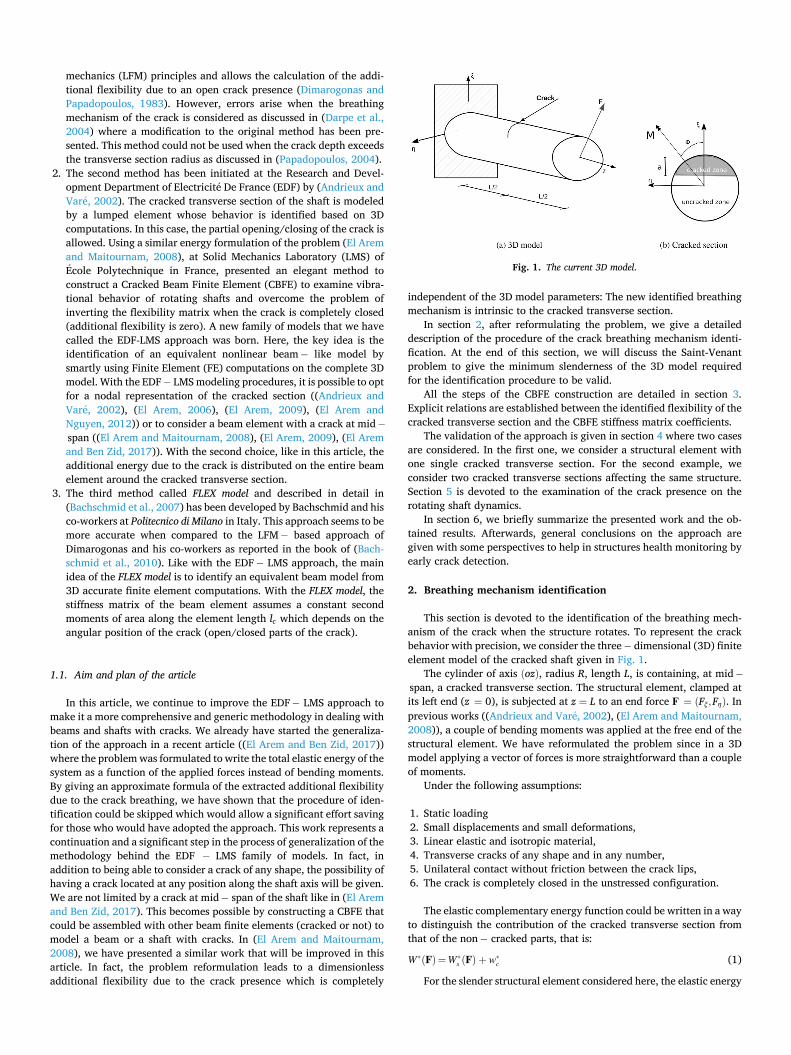
This section is devoted to the identification of the breathing mech-anism of the crack when the structure rotates. To represent the crack behavior with precision, we consider the three − dimensional (3D) finite element model of the cracked shaft given in Fig. 1.
The cylinder of axis (oz), radius R, length L, is containing, at mid −
span, a cracked transverse section. The structural element, clamped at its left end (z = 0), is subjected at z = L to an end force F = (Fξ,Fη). In previous works ((Andrieux and Vare, 2002), (El Arem and Maitournam, 2008)), a couple of bending moments was applied at the free end of the structural element. We have reformulated the problem since in a 3D model applying a vector of forces is more straightforward than a couple of moments.
Under the following assumptions:
1. Static loading2. Small displacements and small deformations,3. Linear elastic and isotropic material,4. Transverse cracks of any shape and in any number,5. Unilateral contact without friction between the crack lips,6. The crack is completely closed in the unstressed configuration.
The elastic complementary energy function could be written in a wayto distinguish the contribution of the cracked transverse section from that of the non − cracked parts, that is:
W∗(F)=W∗s (F) + w∗
c (1)
For the slender structural element considered here, the elastic energy
Fig. 1. The current 3D model.

of the non − cracked parts, W∗s (F), could be approximated by the
equivalent elastic beam energy. We write:
W∗s (F)=
L3
6EI
F
2
(2)
is the quadratic moment of inertia and E the Young’s modulus of the material. We have shown in (El Arem, 2009) that the breathing mech-anism of the crack depends mainly on the resultant bending moments at the cracked transverse section of the shaft. Also, in this article, we wanted to remove the dependence of w∗
c on L that the identified breathing mechanism becomes intrinsic to the cracked transverse sec-tion as proposed by (El Arem and Ben Zid, 2017). With this in mind, the additional elastic energy due to the crack could be written as:
w∗c =w∗
c(M)=2
3πER3 H(M)
M
2
(3)
where M = (Mξ,Mη) is the resulting couple of bending moments at the
cracked transverse section (
z = L2
)
. H(M) is a dimensionless coefficient
depending on M that concentrates the crack breathing mechanism description.
Also, it was shown in ((Andrieux and Vare, 2002), (El Arem, 2006)) that the breathing mechanism of the crack is independent of the bending moment module ||M|| and depends only on its direction. This property is due to the fact that, with the assumptions given above, the contact surfaces area depends only on the bending moment direction. Therefore, by choosing
M=(cos(Φ), sin(Φ)), with Φ ∈ [0, 2π[
the additional energy due to the crack could be written as:
w∗c =w∗
c(M) =2
3πER3 H(Φ) (4)
We can notice here that by exploiting the elastic energy properties, the breathing mechanism characterization is reduced to the computa-tion of the function H(Φ) for Φ varying in [0, 2π[. H is a measure of the open parts of the crack. It is zero when the crack is completely closed.
2.1. Identification procedure of the dimensionless flexibility H
3D computations have been carried out to determine H for the case presented in Fig. 1. The structure contains a crack with a rectilinear tip at mid − span. Of course, the process will remain unchanged when a different crack shape is considered like cracks with elliptical front which could be more realistic in some situations (Han and Chu, 2011).
2.2. Energy of the problem
The clamped shaft element is subjected to F at its free end, and the angle Φ is varied in [0,2π[. The identification of H also requires the realization of similar computations on the non − cracked structure. Knowing the external force vector (F) and the displacement vector (u) at the free end, it becomes possible to quantify the total work of the external forces which is equal to the stored elastic energy and given by:
12
F⋅u
with this formula of Clapeyron we evaluate W∗s and of the non − cracked
and the cracked structures, respectively. w∗c is obtained by:
w∗c(Φ)=W∗(Φ) − W∗
s (Φ) , ∀Φ ∈[0, 2π
[(5)
then H is computed using:
H(Φ)=w∗c(Φ)
3πER3
2 , ∀Φ ∈
[
0, 2π[
(6)
All the computations presented in this article have been carried out on cracks with straight tip similar to Fig. 1(b).
In Fig. 2 we show that the evolution from totally open to totally closed crack is smooth and regular. For cracks with a relative depth aR < 1.0, the crack is fully open when Φ = 3π
2 and closes completely on an interval around Φ = π
2, cf. Fig. 2(a). In fact, shallow cracks may remain totally into the compressed part of the cracked cross section when Φ is around π
2 before going gradually into the taut zone and start to open. Consequently, the shallower the crack, the wider the interval of total closing around Φ = π
2 which is confirmed by the 3D computations. When aR = 1, the crack opens totally only at Φ = π
2. For deep cracks with a
R > 1.0, Fig. 2(b) shows that we can consider that they close completely at Φ = π
2 where we have an absolute minimum of H. In fact, because of the crack, the neutral axis (axis with no longi-tudinal stresses) is not located at the geometric centroid like in the classical elastic beam theory. Thus, we do not have a taut half − section and a compressed half. Also, deep cracks open totally at Φ = 3π
2 for the same reason.
In (El Arem and Ben Zid, 2017), it was noticed that deep cracks like described above never close completely. The difference with the current work is that the forces considered in (El Arem and Ben Zid, 2017) are applied at the cracked transverse section, and the system energy is computed using the corresponding displacements. We think that by having, like here, the applied forces far from the cracked section, the problem solution (displacements, stress and strain fields) are less disturbed by the crack presence as per the Saint − Venant theorem.
Fig. 2. Dimensionless flexibility H.

2.3. The induced Saint-Venant problem
A question is always raised when it comes to identifying a beam model from 3D representation: From which slenderness (ratio L
D here) does the identified behavior become invariable ? It is a Saint-Venant problem as discussed in (Palama, 1976; El Arem, 2006) and the answer is given in Fig. 3 where it is clear that from LD ≥ 2.0 the additional flexibility coefficient H becomes independent of the structure slenderness.
2.4. Approximation of H
For those who will have adopted the EDF − LMS approach, we give, in this section, an approximation of H for cracks with rectilinear tip and depths to a
R = 1.30. In Fig. 4 we present the maximum of additional flexibility coefficient
for Φ ∈ [0, 2π[ (max(H)) as a function of the relative depth of the crack (
aR
). By adopting a polynomial fitting we wrote:
max(H)(a
R
)=Pa
(aR
)=∑7
i=0ci
(aR
)i(7)
Also, we have found that a good fitting of the values of H would be: with Q a polynomial function of a
R given by:
H(Φ)=max(H)
sin(π
4−
Φ2
)
Qa
(aR
)
=Pa
(aR
)sin(π
4−
Φ2
)Qa
(aR
)
(8)
Qa
(aR
)=∑7
i=0qi
(aR
)i(9)
Coefficients ci and qi are given in Table 1. In Fig. 5 we can see that the nonlinear fitting of H using (8) produces
an excellent fitting for cracks with rectilinear tip and width up to aR =
1.30. Now that we have identified the additional elastic energy due to a
crack presence in a slender structure, it becomes possible to relate the applied forces to the (dual) displacements for any similar cantilever beam with a crack at mid − span. Similar analysis has been conducted in (El Arem and Ben Zid, 2017) for a bi − clamped structure. However, for an approach to be more generic, it have to be capable of handling problems of beams with multiple cracks of different depths and located at different positions along the beam axis. To solve this problem, we present in the following section the technique of construction of a CBFE.
2.5. A cracked beam finite element construction
In this section, we will show step by step how to construct the stiff-ness matrix of an elastic beam finite element with a crack at mid − span. This CBFE could be later assembled with other cracked or non − cracked beam elements to model a complete shaft with cracks at different posi-tions and depths. Actually, there exist another method to introduce the local flexibility generated by a cracked transverse section to model a cracked structural element. It consists in the construction of a stiffness matrix exclusively for the cracked section by computing the inverse of the flexibility matrix. This technique leads to very large stiffness co-efficients in the case of a very small additional flexibility due to small cracks. In such situation the numerical integration of the differential equations in dynamics becomes very time consuming and convergence problems arise as outlined in (El Arem, 2006). For these reasons, we have chosen to construct a CBFE and this technique has been used in works by (Saavedra and Cuitino, 2001) and (El Arem and Maitournam, 2008).
The study of (El Arem, 2009) has showed that the shear effects on the breathing mechanism of the cracks is insignificant and will be neglected in this study.
2.6. Stiffness matrix construction procedure
The procedure of construction has already been presented by (El Arem and Maitournam, 2008). However, to have the current work self-contained and to easily highlight the new improvements of the EDF − LMS approach, we will go through all the steps of the CBFE construction procedure.
Let establish the stiffness matrix of the CBFE of length 2Le, circular transverse section of radius R and quadratic moment of inertia I, cf. Fig. 6.
Fig. 3. Saint Venant problem: H for varying slenderness for.aR = 1.00
Fig. 4. Maximum of H as a function of crack depth.
Table 1 Coefficients of the polynomial functions Pa and.Qa
i = 0 i = 1 i = 2 i = 3 i = 4 i = 5 i = 6 i = 7
ci − 2.28e-4 0.2301 − 2.2693 57.88186 − 140.4437 195.1568 − 134.2555 39.3306 qi 0.0045 0.0847 − 0.5679 1.7771 − 3.0003 2.7866 − 1.3376 0.2592

Let first clamp all the displacements of node A. The relation between the loading and displacements vectors at the end section (z = 2Le) could be written as:
u= S(F)⋅F (10)
Here S(F) represents the compliance matrix of the cantilever cracked element. F = {Tx2 ,Ty2 ,Mx2 ,My2}
t and u = {ux2 , uy2 , θx2 , θy2}t denote,
respectively, the loading and displacements vectors at the end section (z = 2Le).
When using the classical elastic beam theory, internal efforts at the cracked section ( z = Le), are given by: ⎧⎪⎪⎨
⎪⎪⎩
Tx = Tx2
Ty = Ty2
Mx = Mx2 − LeTyMy = My2 + LeTx
(11)
As mentioned in the precedent section, the breathing mechanism of
the cracks is governed by the bending moment direction Φ = atan(
MyMx
)
at the cracked section. The elastic energy of the cracked element is given by:
W∗(F)=W∗s (F)+w∗
c(M)=W∗s (F) +
23πER3 H(Φ)
M
2
(12)
The nonlinear relation between the applied forces vector and the resulting displacements vector at the end section (z = 2Le)are obtained by derivation of the function W∗ by F. Thus, by using (11), we write
u= S(F)⋅F = S(Φ)⋅F (13)
where
S0 denotes the compliance matrix of a non − cracked beam element of length 2Le. Let call {uB/A} the relative displacement of node B with respect to node A. It verifies the relation
{Tx2 , Ty2 ,Mx2 ,My2
}t=(S(Φ))
− 1{uB/A}
(15)
Using the equilibrium conditions of the element of the CBFE of Fig. 6, the internal forces in B can be expressed in terms of those in A as: ⎧⎪⎪⎨
⎪⎪⎩
Tx1 = − Tx2
Ty1 = − Ty2
Mx1 = − Mx2 + 2LeTy2
My1 = − My2 − 2LeTx2
(16)
which, in a matrix form, gives: {
Tx1 , Ty1 ,Mx1 ,My1 ,Tx2 ,Ty2 ,Mx2 ,My2
}t=Π1
{Tx2 ,Ty2 ,Mx2 ,My2
}t (17)
Fig. 5. Approximation of.H
S(Φ)= S0 +4
3πER3
⎛
⎜⎜⎜⎜⎜⎜⎜⎜⎜⎜⎜⎜⎝
L2eH(Φ) −
L2e
2H’(Φ)
Le
2H’(Φ) LeH(Φ)
L2e
2H’(Φ)L2
eH(Φ)− LeH(Φ)Le
2H’(Φ) −
Le
2H’(Φ)
− LeH(Φ) H(Φ) −12
H’(Φ)
LeH(Φ) −Le
2H’(Φ)
12
H’(Φ) H(Φ)
⎞
⎟⎟⎟⎟⎟⎟⎟⎟⎟⎟⎟⎟⎠
(14)
Fig. 6. The cracked beam finite element.

with Π1 =
⎛
⎜⎜⎜⎜⎜⎜⎜⎜⎜⎜⎝
− 1 0 0 00 − 1 0 0
02Le− 10− 2Le0 0 − 1
1 0 0 00 1 0 00 0 1 00 0 0 1
⎞
⎟⎟⎟⎟⎟⎟⎟⎟⎟⎟⎠
(18)
2.7. In addition, when writing uB/A in the form
uB/A ={
u1B/A, u
2B/A, u3
B/A, u4B/A
}
we obtain ⎧⎪⎪⎪⎪⎪⎪⎪⎨
⎪⎪⎪⎪⎪⎪⎪⎩
ux2 = u1B/A + ux1 + 2Leθy1
uy2 = u2B/A + uy1 − 2Leθx1
θx2 = u3B/A + θx1
θy2 = u4B/A + θy1
(19)
which could be written in a matrix form as:
uB/A =Π2⋅{
ux1 , uy1 , θx1 , θy1 , ux2 , uy2 , θx2 , θy2
}t (20)
where Π2 =
⎛
⎜⎜⎝
− 1 0 0 − 2Le 1 0 0 00 − 1 2Le 0 0 1 0 00 0 − 1 0 0 0 1 00 0 0 − 1 0 0 0 1
⎞
⎟⎟⎠ (21)
Comparing with equation (18), it can be seen that:
Π2 =Πt1
2.8. Moreover, the CBFE stiffness matrix KFE verifies
{Tx1 ,Ty1 ,Mx1 ,My1 ,Tx2 , Ty2 ,Mx2 ,My2
}t=
KFE⋅{
ux1 , uy1 , θx1 , θy1 , ux2 , uy2 , θx2 , θy2
}t (22)
Substituting equation (17) into equation (22) gives
Π1{
Tx2 ,Ty2 ,Mx2 ,My2
}t=KFE⋅
{ux1 , uy1 , θx1 , θy1 , ux2 , uy2 , θx2 , θy2
}t (23)
Then, substituting equation (15) into equation (23), results in
Π1 ⋅ (S(Φ))− 1 ⋅ uB/A =KFE⋅
{ux1 , uy1 , θx1 , θy1 , ux2 , uy2 , θx2 , θy2
}t (24)
Finally, using equation (20) leads to:
KFE =Π1 ⋅ (S(Φ))− 1⋅Πt
1 (25)
In this relation, the stiffness matrix appears as depending on the applied loading represented by angle Φ. However, in a finite element code, it is preferable to express relation (25) as a function of the prob-lem’s unknowns, that is the nodal degrees of freedom. Also, in an experimental setting, we most of the time do not have access to the resulting stress at a given point, but we could measure accurately the displacements. We start by writing:
KFE(α)=Π1⋅K(α)⋅Πt1 (26)
with
(S(Φ))− 1
=K(α)=K0 − Δk(α) (27)
In (27), we distinguish the stiffness matrix of a non − cracked beam element of length 2Le, Π1K0Πt
1, from the matrix modeling the stiffness loss due to the crack presence Π1Δk(α)Πt
1. K0 is given by:
K0 = S− 10 =
EI2Le(1 + a)
⎛
⎜⎜⎜⎜⎜⎜⎜⎜⎜⎜⎜⎝
3L2
e0 0 −
3Le
03L2
e
3Le
0
03Le
4 + a0 −3Le
0 0 4 + a
⎞
⎟⎟⎟⎟⎟⎟⎟⎟⎟⎟⎟⎠
(28)
a = 12EI4μkSL2
e is the shearing effects coefficient. For a Euler − Bernoulli beam
element, a is zero. α is the angle given by α = atan(
[θy ]
[θx ]
)
=
arctan(
θy2 − θy1θx2 − θx1
)
. [θx] and [θy] are the rotations discontinuities at the
cracked section. If we consider that Φ is the primal variable of the problem, α is its dual. The relationship between Φ and α is an one − to −
one mapping function which is not the case when considering the nodal representation of the cracked transverse section. Equation (27) leads to
Δk(α)=K0 − (S(Φ))− 1
=EI2Le
⎛
⎜⎜⎝
0 0 0 00 0 0 00 0 kxx(α) kxy(α)0 0 kyx(α) kyy(α)
⎞
⎟⎟⎠ (29)
where
Fig. 7. 3D and beam modeling of the system.
⎧⎪⎪⎪⎪⎪⎨
⎪⎪⎪⎪⎪⎩
kxx(α)=kyy(α)=4R2 H(Φ)(Φ)
2+24RLe H(Φ)+R2 H’(Φ)
2
4R2 H(Φ)(Φ)2+48RLeH(Φ)+R2 H’(Φ)
2+144L2
e
kxy(α)=− kyx(α)=−12Le RH’(Φ)
4R2 H(Φ)(Φ)2+48RLeH(Φ)+R2 H’(Φ)
2+144L2
e
(30)
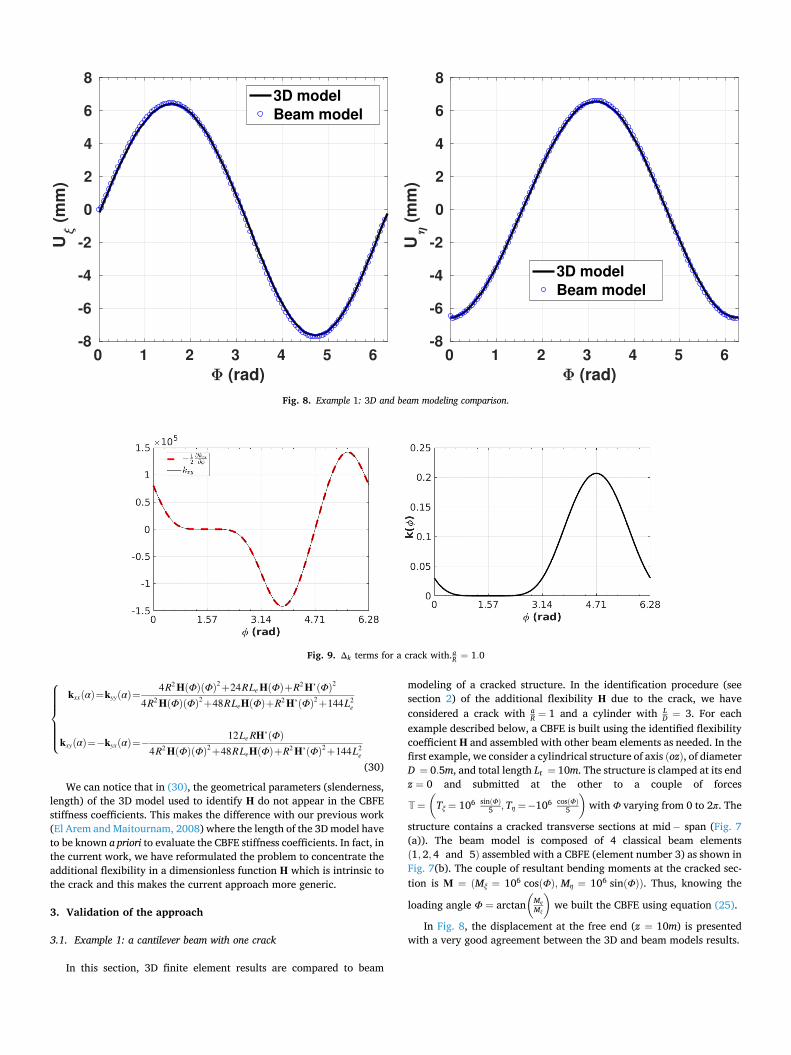
We can notice that in (30), the geometrical parameters (slenderness, length) of the 3D model used to identify H do not appear in the CBFE stiffness coefficients. This makes the difference with our previous work (El Arem and Maitournam, 2008) where the length of the 3D model have to be known a priori to evaluate the CBFE stiffness coefficients. In fact, in the current work, we have reformulated the problem to concentrate the additional flexibility in a dimensionless function H which is intrinsic to the crack and this makes the current approach more generic.
3. Validation of the approach
3.1. Example 1: a cantilever beam with one crack
In this section, 3D finite element results are compared to beam
modeling of a cracked structure. In the identification procedure (see section 2) of the additional flexibility H due to the crack, we have considered a crack with a
R = 1 and a cylinder with LD = 3. For each
example described below, a CBFE is built using the identified flexibility coefficient H and assembled with other beam elements as needed. In the first example, we consider a cylindrical structure of axis (oz), of diameter D = 0.5m, and total length Lt = 10m. The structure is clamped at its end z = 0 and submitted at the other to a couple of forces
T=
(
Tξ = 106 sin(Φ)
5 ,Tη = − 106 cos(Φ)
5
)
with Φ varying from 0 to 2π. The
structure contains a cracked transverse sections at mid − span (Fig. 7 (a)). The beam model is composed of 4 classical beam elements (1, 2,4 and 5) assembled with a CBFE (element number 3) as shown in Fig. 7(b). The couple of resultant bending moments at the cracked sec-tion is M = (Mξ = 106 cos(Φ), Mη = 106 sin(Φ)). Thus, knowing the
loading angle Φ = arctan(
MηMξ
)
we built the CBFE using equation (25).
In Fig. 8, the displacement at the free end (z = 10m) is presented with a very good agreement between the 3D and beam models results.
Fig. 8. Example 1: 3D and beam modeling comparison.
Fig. 9. Δk terms for a crack with.aR = 1.0

3.2. Discussion
Before presenting the second example, let’s be back to equation (30) because we have expressed Δk as an explicit function of the loading angle Φ instead of α. With the beam model of Fig. 7(b) we have
computed α = arctan(
[θy ]
[θx ]
)
and found that
α=Φ (31)
which confirms the fact that, for a given loading direction Φ, the me-chanical system is linear but with a different stiffness coefficient for each Φ.
Also, Fig. 9 shows that, when plotting kxx(α) and kxy(α), it appears that:
kxy(α)= −12
k’xx(α) = −12
∂kxx(α)∂α (32)
Thus, Δk(α)can be written in the form:
Δk(α)=EI2Le
⎛
⎜⎜⎜⎜⎜⎜⎜⎜⎝
0 0 0 0
0 0 0 0
0 0 k(α) −12
k’(α)
0 012
k’(α) k(α)
⎞
⎟⎟⎟⎟⎟⎟⎟⎟⎠
(33)
with
k(α)= kxx(α) = kyy(α) and k’(α) = ∂k(α)∂α
Here again we have found the famous skew − symmetric form of the matrix describing the stiffness loss due to the crack. This form was dis-scussed in many article ((Andrieux and Vare, 2002), (El Arem, 2019a), (El Arem and Ben Zid, 2017)) and is intimately related to the way we have written the system elastic energy and its derivative that gives the
Fig. 10. 3D and beam modeling of the system.
Fig. 11. Example 2: 3D and beam modeling comparison.
nonlinear relation describing the crack breathing. We can say that it is the signature of the EDF − LMS family of models where the breathing mechanism is completely described by the variation of one single function: k(α)or. H(Φ)
3.3. Example 2: a cantilever beam with two cracks
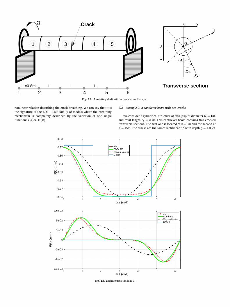
We consider a cylindrical structure of axis (oz), of diameter D = 1m, and total length Lt = 20m. This cantilever beam contains two cracked transverse sections. The first one is located at z = 5m and the second at z = 15m. The cracks are the same: rectilinear tip with depth aR = 1.0, cf.
Fig. 12. A rotating shaft with a crack at mid − span.
Fig. 13. Displacements at node 3.

Fig. 10(a). The beam model is composed of 8 classical beam elements (1, 2, 4,5, 6,7, 9 and 10) assembled with two CBFE (elements 3 and 8) as shown in Fig. 10(b). All the elements are of length L0 = 2m, diameter D = 1m. Knowing the crack geometry we have the flexibility coefficient already computed using the approximation formula (8). Then, using (30) we have computed the CBFE stiffness matrix coefficients.
The structure is clamped at its end z = 0 and submitted at the other to a couple of forces T = (Tξ = 106 cos(β), Tη = 106 sin(β)) with β varying in [0,2π[. In this example, for each loading angle β we solve:
f (U)= 0=K(U) ⋅ U − F=K(α3, α8) ⋅ U − F (34)
using the iterative Newton − Raphson method. U is the nodal unknowns, F the nodal forces and K the stiffness
matrix of the structure. In general, the bending moment at the cracked
section is unknown and equation (34) is used in finite element analysis to solve for U.
Thus, at each iteration, we build the CBFE stiffness matrices of ele-ments 3 and 8, K3
EF(α3) and K8EF(α8) and assemble them with the non −
cracked elements stiffness matrices until convergence of the iterative algorithm. For the CBFE number i, αi is given by:
αi = arctan([
θy]
[θx]
)
= arctan
(θr
y − θly
θrx − θl
x
)
, i= 3, 8
The superscripts r and l are for the right node and the left node of the CBFE number i, respectively.
In Fig. 11, the displacement at the free end (z = 20m) is presented with a very good agreement between the 3D and beam models results which completes the validation of our approach.
Fig. 14. Phase portrait at node 3. d = 0.03
3.4. Nonlinear dynamics of a rotating beam with a breathing crack
Some aspects of the nonlinear behavior of a rotating shaft with a breathing crack are addressed in this section. Although it is not the main objective of this paper, we think that it is necessary to show that the most known effects of a crack presence on the dynamics of a rotating shaft could be obtained with our approach.
Crack detection in rotating shafts by vibration measurements re-mains a challenging problem for engineers and scientists ((El Arem, 2019b), (Spagnol et al., 2018), (Dotti et al., 2016), (Liu and Wang, 2016), (Varney and Green, 2013)). The analysis of the vibrational behavior of a rotating shaft aims at providing parameters that could help in early crack detection. This problem has been dealt with intensively in
recent years because of its relevance for many sectors like power gen-eration, aeronautics, aerospace and transportation ((Dimarogonas, 1996; Bachschmid et al., 2010; El Arem, 2006)). It was shown in many articles (Patel and Darpe, 2008; El Arem and Nguyen, 2012; El Arem, 2019a; AL-Shudeifat et al., 2010; Han and Chu, 2012; Han and Chu, 2013) that the crack breathing mechanism modeling strongly influences the dynamics of a rotating shaft.
In Fig. 12, we consider a rotating shaft of diameter D = 2R = 0.10m, distributed mass m0 = πR2ρ, with ρ = 7800kg/m3. d = 3% is the viscous damping. The structure is composed of 5 beam elements of length L =
0.8m and rotating at the frequency Ω about its axis. To model a cracked section at mid − span, a CBFE (element number 3) is assembled with 4 non-cracked beam elements. The shaft is clamped at its both ends and
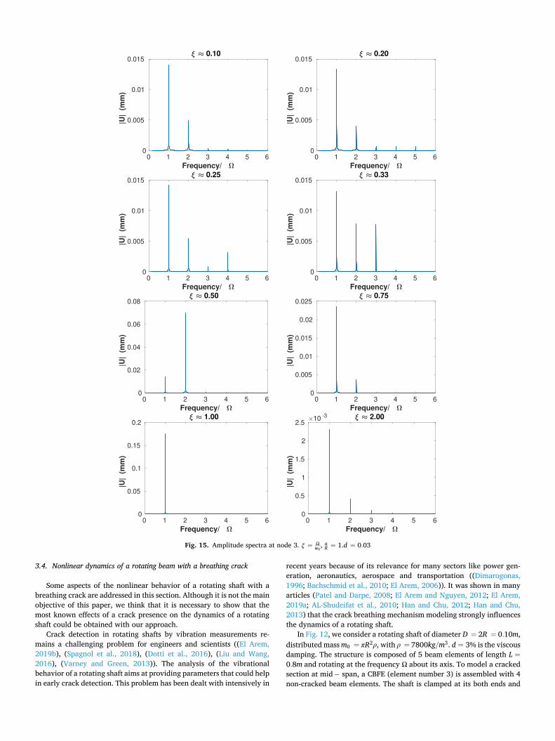
Fig. 15. Amplitude spectra at node 3. ξ = Ωw0
, aR = 1.d = 0.03

subjected to the effects of its self-weight. (Oxy) is the inertial non- rotating frame and (Gζη) the body-fixed rotating frame. G is the center of transverse section of the shaft.
First, lets start by looking at the crack breathing during one full rotation of the shaft. Here, under its self-weight, the shaft is rotating at a very weak rotating frequency Ω and inertial effects are not considered. We can see on Fig. 13, that the current model gives a better represen-tation of the crack breathing phenomena when compared to the swithching crack model of (Gasch, 1993) or the model of (Mayes and Davies, 1976). When compared to 3D computations, the EDF − LMS model provides an excellent agreement especially when the crack starts
to close (Ωt ∈[
π2,
3π2
]
). Also, when looking at the displacement V(t), we
can see that only the current model gives satisfactory results. Moreover, in the classical models the breathing mechanism depends only on the angular position of the crack Ωt and could be adopted only with heavy, horizontal axis, well damped rotating shafts where weight-governed oscillations are dominant. However, the new generation of turbines in power stations are light weight and often operated at very high fre-quencies wich makes the vibration levels effects of the same order of magnitude than the self-weight deflection. Also, the machine self-weight is not the dominant loading in vertical axis machines. Consequently, in the two cases mentioned above, the hypothesis of weight dominant situation could not be accepted.
Now that we have carrefully examined the breathing of the crack with the shaft rotation, we can confidently start a brief analysis of the dynamical behavior of the shaft.
Fig. 14 shows phase portraits at different rotating frequencies Ω. The superharmonic resonance phenomena is observed when Ω is a subdivi-sion of the first critical frequency w0 of the non-cracked structure. Consequently, the phase portrait and the shaft whirl orbit is composed of
intertwined loops when (
ξ = Ωw0≈ 1
5 ,14 ,13 ,12). This phenomenon has been
observed and described in many articles considering a switching crack model (Gasch, 1993; Patel and Darpe, 2008; El Arem, 2019a) or a more realistic description of the breathing crack as presented in (El Arem and Maitournam, 2008; El Arem and Nguyen, 2012).
In the subcritical rotating frequencies zones, variation of higher- order harmonics components is shown in the amplitude spectra of Fig. 15. This noticeable variation was experimentally observed in (Sinou, 2009a; Guo et al., 2017; Zhou et al., 2004) as well as the whirl orbit changing shape during the passage through one-half and one-third of the first critical rotating frequency.
Fig. 16 shows, for a supercritical rotating frequency (ξ≈ 2.0), the increase of both the Mean Static Total Deflection (MSTD) and the first two harmonics components with the crack depth. We have noticed this increase in previous articles (El Arem and Nguyen, 2012; El Arem, 2019a) dealing with the numerical exploration of the nonlinear dy-namics of a cracked shaft using a simple mechanical system composed of two rigid bars connected with a nonlinear bending spring. Also, exper-imental investigations presented in (Sinou, 2009b) showed the increase of the 2× and 3× harmonics with the crack depth.
4. Conclusions and perspectives
In this article, we dealt with the problem of modeling beams andshafts with cracks. It is a problem with high interest especially for en-gineers and scientists in the power generation and transportation in-dustries where cracks have to be detected before a turbine failure. The problem is complex because the cracks breath when the shaft rotates. We have presented a generic methodology to deal with the mechanics of such complex and often expensive structures. Compared to our previous works, the new improvements of the EDF − LMS approach could be summarized in three points:
1. The problem of identifying the breathing mechanism of the crack isreformulated to consider a 3D cracked structure under applied forcesand not bending moments as before (Andrieux and Vare, 2002; ElArem and Maitournam, 2007, 2008). In fact, in 3D models, applyingforces is more straightforward. Otherwise, unlike our previous work(El Arem and Ben Zid, 2017), the forces considered in the identifi-cation process are applied away from the cracked transverse sectionso that the problem solution (stresses and displacements) is notaffected by the contact conditions on the crack lips.
2. The identified dimensionless flexibility H measures the open/closedparts of the crack. H is exclusively inherent to the crack geometryand completely independent of the geometrical parameters of the 3Dmodel used to identify it.
3. Consequently, the dependence of the CBFE stiffness coefficients onthese parameters has been removed which makes a major improve-ment of our previous work (El Arem and Maitournam, 2008).
In fact, we have reformulated the problem of identifying the crackbreathing mechanism to concentrate the flexibility variation in a dimensionless function H which is intrinsic to the cracked transverse section. Moreover, we have given a nonlinear fitting formula for H that
Fig. 16. Static deflection, 1 × Ωand 2 × Ω harmonics amplitude increase with crack depth.ξ = Ωw0
= 2.0

all the process of identification could be skipped when a cracked transverse section is to be inserted in a beam-like model of a cracked shaft or beam. This standard and generic methodology is completed by a detailed description of the technique of construction of a CBFE. A vali-dation of the approach under static loading is given for a cantilever beam with one, then two cracked transverse sections and an excellent agreement has been found when the results are compared to 3D com-putations. Also, we have explored the vibrational behavior of rotating shaft with a cracked transverse section at mid − span. We have found, as well established in the literature, that a crack presence induces higher harmonics in the vibratory response of the cracked shaft. Also, we have noticed a remarkable increase in the MSTD and the higher-harmonics components with the crack depth. These parameters, as discussed in many previous works, could help in early crack detection.
We think that we have given a very original, standard and generic way to deal with the problem of cracked shafts and beams. The next step is to use the CBFE in exploring the nonlinear dynamics of multi-cracked shafts to develop reliable procedures for online cracks detection. After almost twenty years of continuous improvements, we think that the EDF − LMS approach is now sufficiently mature to find its way to be adopted by engineers and scientists in the analysis of cracked beams and shafts or followed in modeling other type of cracked structures like plates and shells.
CRediT authorship contribution statement
Saber El Arem: Conceptualization, Methodology, Software, Re-sources, Writing - original draft, Visualization, Investigation, Writing - review & editing.
Declaration of competing interest
The authors declare that they have no known competing financial interests or personal relationships that could have appeared to influence the work reported in this paper.
Acknowledgments
I would like to offer special thanks to Huy Duong BUI for the very helpful discussions on Saint Venant theorem during my PhD preparation at LMS, Ecole Polytechnique, France. Although no longer with us, Huy Duong BUI continues to inspire by his example and dedication.
References
Al-Shudeifat, M.A., Butcher, E.A., Stern, C.R., 2010. General harmonic balance solution of a cracked rotor-bearing-disk system for harmonic and sub-harmonic analysis: analytical and experimental approach. Structural Health Monitoring in the Light of Inverse Problems of Mechanics Int. J. Eng. Sci. 48 (10), 921–935.
Andrieux, S., Vare, C., 2002. A 3d cracked beam model with unilateral contact- application to rotors. Eur. J. Mech. Solid. 21, 793–810.
Bachschmid, N., Pennacchi, P., Tanz, E., 2007. Rotating shafts affected by transverse cracks: experimental behaviour and modelling techniques. Int. J. Mater. Struct. Integr. 1 (1–2-3), 71–116.
Bachschmid, N., Pennacchi, P., Tanzi, E., 2009. Cracked Rotors: A Survey on Static and Dynamic Behaviour Including Modelling and Diagnosis. Springer.
Bachschmid, N., Tanzi, E., Pennacchi, P., 2010. Cracked Rotors: A Survey on Static and Dynamic Behaviour Including Modelling and Diagnosis. Springer Berlin Heidelberg. https://doi.org/10.1007/978-3-642-01485-7.
Darpe, A.K., Gupta, K., Chawla, A., 2004. Coupled bending, longitudinal and torsional vibrations of a cracked rotor. J. Sound Vib. 269, 33–60.
Dimarogonas, A.D., 1996. Vibration of cracked structures: a state of the art review. Eng. Fract. Mech. 55 (5), 831–857.
Dimarogonas, A.D., Massouros, G., 1981. Torsional vibration of a shaft with a circumferential crack. Eng. Fract. Mech. 15, 439–444.
Dimarogonas, A.D., Papadopoulos, C.A., 1983. Vibration of cracked shafts in bending. J. Sound Vib. 91, 1583–1593, 04.
Dotti, F., Cortinez, V., Reguera, F., 2016. Non-linear dynamic response to simple harmonic excitation of a thin-walled beam with a breathing crack. Appl. Math. Model. 40 (1), 451–467.
El Arem, S., 2006. Vibrations non-lineaires des structures fissurees: application aux rotors de turbines (in french). Ph.D. thesis. Ecole Nationale des Ponts et Chaussees.
El Arem, S., 2009. Shearing effects on the breathing mechanism of a cracked beam section in bi-axial flexure. Eur. J. Mech. Solid. 28, 1079–1087.
El Arem, S., 2019a. Nonlinear analysis, instability and routes to chaos of a cracked rotating shaft. Nonlinear Dynam. 96 (1), 667–683.
El Arem, S., 2019b. Nonlinear analysis, instability and routes to chaos of a cracked rotating shaft. Nonlinear Dynam. 96 (1), 667–683.
El Arem, S., Ben Zid, M., 2017. On a systematic approach for cracked rotating shaft study: breathing mechanism, dynamics and instability. Nonlinear Dynam. 88, 2123–2138.
El Arem, S., Maitournam, H., 2007. Un element fini de poutre fissuree: application a la dynamique des arbres tournants (in French). European Journal of Computational Mechanics 16 (5), 643–663.
El Arem, S., Maitournam, H., 2008. A cracked beam finite element for rotating shaft dynamics and stability analysis. J. Mech. Mater. Struct. 3 (5), 893–910.
El Arem, S., Nguyen, Q.S., 2012. Nonlinear dynamics of a rotating shaft with a breathing crack. Annals of Solid and Structural Mechanics 3 (1), 1–14.
Gasch, R., 1993. A survey of the dynamic behavior of a simple rotating shaft with a transverse crack. J Sound and vibration 160, 313–332.
Guo, C., Yan, J., Yang, W., 2017. Crack detection for a jeffcott rotor with a transverse crack: an experimental investigation. Mech. Syst. Signal Process. 83, 260–271.
Han, Q., Chu, F., 2011. Local flexibility of an elliptical cracked shaft under bending and tension. Mech. Syst. Signal Process. 25 (8), 3198–3203.
Han, Q., Chu, F., 2012. Parametric instability of a rotor-bearing system with two breathing transverse cracks. Eur. J. Mech. Solid. 36, 180–190.
Han, Q., Chu, F., 2013. Parametric instability of a jeffcott rotor with rotationally asymmetric inertia and transverse crack. Nonlinear Dynam. 73 (1–2), 827–842.
Kushwaha, N., Patel, V., 2020. Modelling and analysis of a cracked rotor: a review of the literature and its implications. Arch. Appl. Mech.
Liu, Z., Wang, J.J., 2016. Transient vibration characteristics of a rotor with breathing crack. Zhendong yu Chongji/Journal of Vibration and Shock 35 (7), 233–240.
Mayes, I., Davies, W., 1976. The vibrational behaviour of a rotating shaft system containing a transverse crack. In: Vibrations in Rotating Machinery. Inst. Mech. E. Conference, London, pp. 53–65.
Palama, A., 1976. On saint-venant’s principle in three-dimensional elasticity. Meccanica 11 (2), 98–101.
Papadopoulos, C., 2004. Some comments on the calculation of the local flexibility of cracked shafts. J. Sound Vib. 278, 1205–1211.
Papadopoulos, C.A., 2008. The strain energy release approach for modeling cracks in rotors: a state of the art review. Mech. Syst. Signal Process. 22 (4), 763–789.
Patel, T.H., Darpe, A.K., 2008. Influence of crack breathing model on nonlinear dynamics of a cracked rotor. J. Sound Vib. 311, 953–972.
Saavedra, P.N., Cuitino, L.A., 2001. Crack detection and vibrational behavior of cracked beams. Comput. Struct. 79, 1451–1459.
Sinou, J.J., 2009a. Experimental study on the nonlinear vibrations and nx amplitudes of a rotor with a transverse crack. J. Vib. Acoust. 131 (4), 1–6.
Sinou, J.J., 2009b. Experimental response and vibrational characteristics of a slotted rotor. Commun. Nonlinear Sci. Numer. Simulat. 14 (7), 3179–3194.
Spagnol, J., Wu, H., Xiao, K., 2018. Dynamic response of a cracked rotor with an unbalance influenced breathing mechanism. J. Mech. Sci. Technol. 32 (1), 57–68.
Varney, P., Green, I., 2013. Rotordynamic crack diagnosis: distinguishing crack depth and location. J. Eng. Gas Turbines Power 135 (11). https://doi.org/10.1115/ 1.4025039.
Zhou, T., Sun, Z., Xu, J., Han, W., 2004. Experimental analysis of cracked rotor. J. Dyn. Syst. Meas. Contr. 127 (3), 313–320.