Embed Size (px)
Citation preview
On the menu todayDecay rate engineering
• The electric dipole• Green function• Fields of electric dipole• Power dissipated by an oscillating dipole• The local density of optical states (LDOS)• Decay rate of quantum emitters• Decay rate engineering• Example: Drexhage experiment• Example: The Purcell effect• Example: classical analogue of Drexhage experiment• Example: optical antenna
Optical antennas• Dipolar scattering theory• Radiation damping
www.photonics.ethz.ch 1

Power radiated in inhomogeneous environment
www.photonics.ethz.ch 2
Local density of optical states
• The power dissipated by a dipole depends on its environment and is proportional to the local density of optical states (LDOS).
• The LDOS is (besides prefactors) the imaginary part of the Green’s function evaluated at the origin.
• Controlling the boundary conditions (and thereby the LDOS) allows us to control the power radiated by a dipole!

Power radiated in inhomogeneous environment
www.photonics.ethz.ch 3
Local density of optical states
current
Power dissipated in an electrical circuit:
resistanceLDOS!
Radiation resistance!
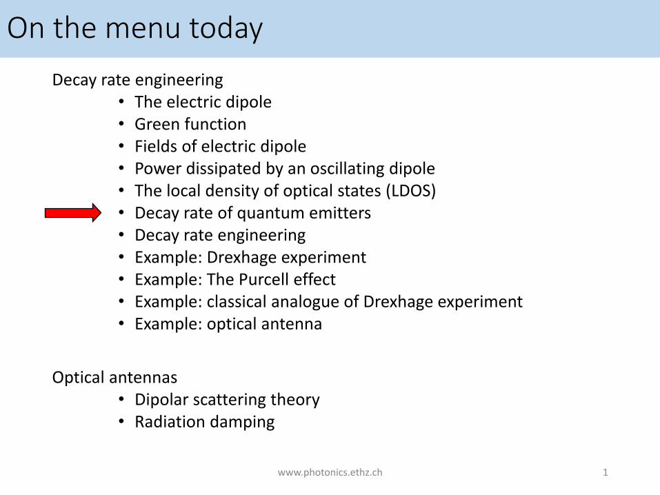
Via the local density of states (LDOS) the power radiated by a dipole depends on• location of source within its environment• frequency of source• orientation of source
The LDOS can be interpreted as a radiation resistance
www.photonics.ethz.ch 6
Power radiated in inhomogeneous environment
In analogy with

Radiating sources at 1000 THz :
Quantum dotsDye moleculesAtoms
Optical emitters have discrete level scheme (in the visible)Let’s focus on the two lowest levelsHow long will the system remain in its excited state?
www.photonics.ethz.ch 9
Quantum emitters

The probability to detect a photon at time t is proportional to p(t)!1. Prepare system in excited state with
light pulse at t=02. Record time delay t13. Repeat experiment many times4. Histogram arrival time delays
detectormolecule t1 t2 t3
www.photonics.ethz.ch 10
Fluorescence lifetime measurements
time
decay rate lifetime
Think about an application (beyond academic interest) for fluorescence lifetime measurements!

Fermi’s Golden Rule:
Initial state (excited atom, no photon):
Final state (de-excited atom, 1 photon in state k at frequency omega):
www.photonics.ethz.ch 11
Calculation of decay rate γ

www.photonics.ethz.ch 12
The Wigner-Weisskopf approximation

Sum over final states is sum over photon states (k) at transition frequency ω.
www.photonics.ethz.ch 13
Calculation of decay rate γFermi’s Golden Rule:
Initial state (excited atom, no photon):
Final state (de-excited atom, 1 photon in state k at frequency ω):
Interaction Hamiltonian:
Atomic part: transition dipole moment (quantum)
Field part: Local density of states (classical)

EmitterTransition dipole moment:Wave function engineering by synthesizing molecules, and quantum dots
Chemistry, material science
EnvironmentLDOS: Electromagnetic mode engineering by shaping boundary conditions for Maxwell’s equations
Physics, electrical engineering
www.photonics.ethz.chantennaking.com, Wikimedia, emory.edu 14
Decay rate engineering
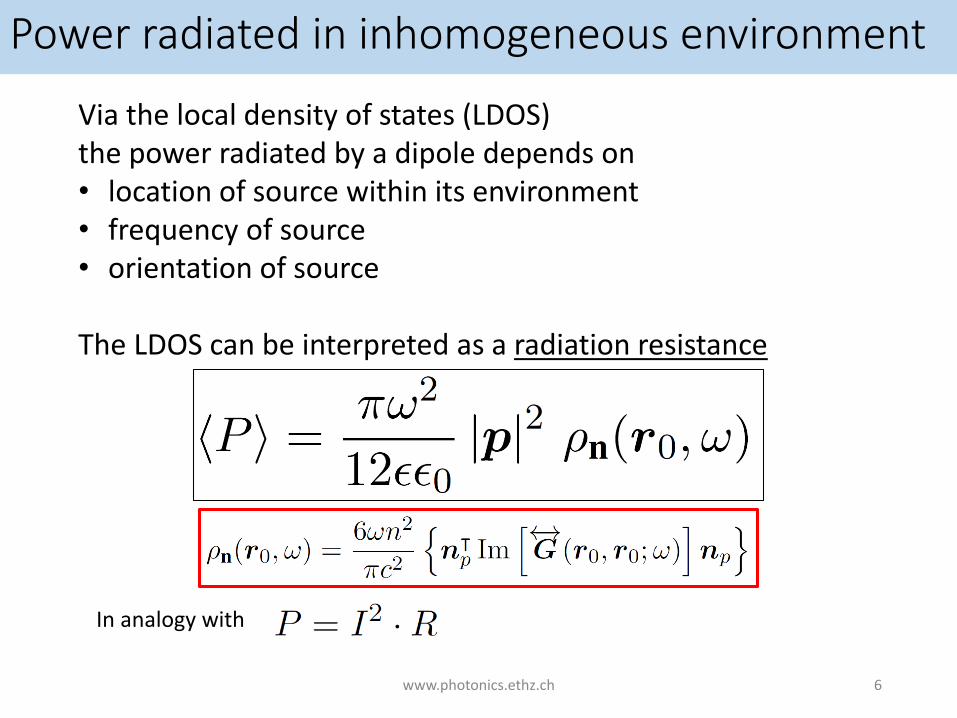
Transition dipole moment is NOT classical dipole moment, but
Classical electromagnetism CANNOT make a statement about the absolute decay rate of a quantum emitter.BUT: Classical electromagnetism CAN predict the decay rate enhancement provided by a photonic system as compared to a reference system.
www.photonics.ethz.ch 15
Rate enhancement – quantum vs. classical
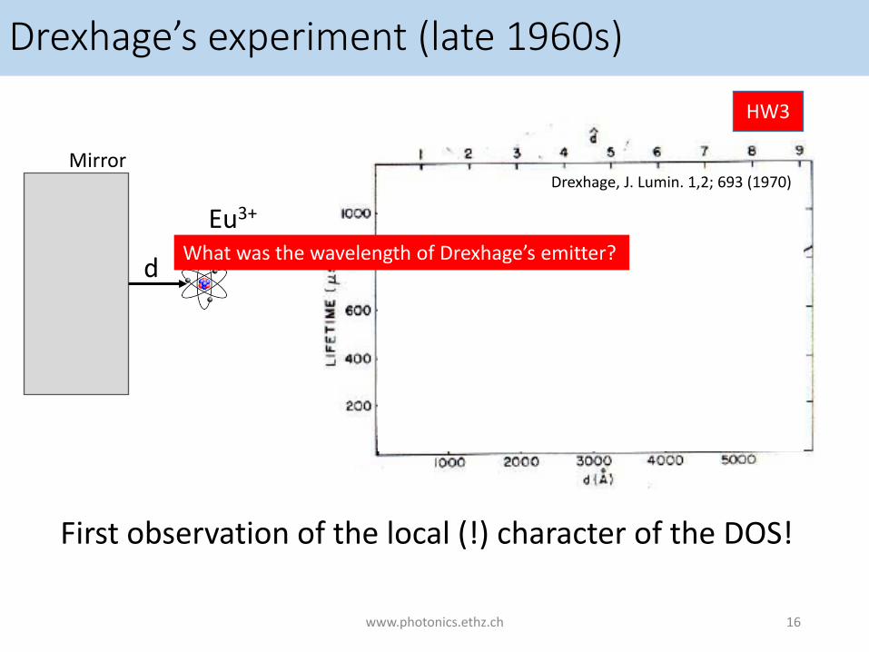
Drexhage’s experiment (late 1960s)
First observation of the local (!) character of the DOS!
www.photonics.ethz.ch 16
Mirror
Eu3+
d
HW3
Drexhage, J. Lumin. 1,2; 693 (1970)
What was the wavelength of Drexhage’s emitter?

Drexhage’s experiment (late 1960s)
Emitter sees its own mirror image.Gs is given as the field generated by the mirror dipole.
www.photonics.ethz.ch 17
Mirror
Eu3+
d
HW3
Drexhage, J. Lumin. 1,2; 693 (1970)
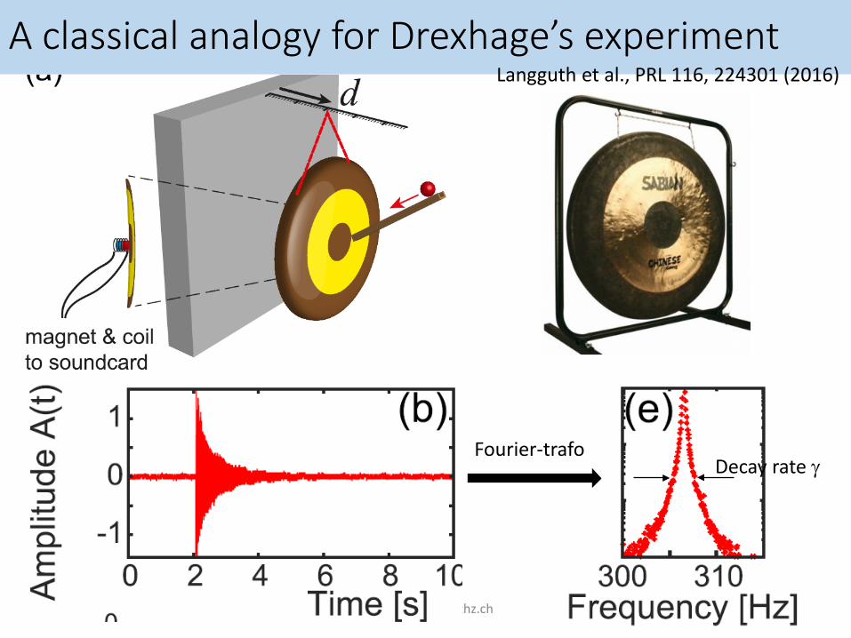
A classical analogy for Drexhage’s experiment
www.photonics.ethz.ch 18
Langguth et al., PRL 116, 224301 (2016)
Fourier-trafoDecay rate γ

A classical analogy for Drexhage’s experiment
www.photonics.ethz.ch 19
Langguth et al., PRL 116, 224301 (2016)
Fourier-trafoDecay rate γ

A classical analogy for Drexhage’s experiment
www.photonics.ethz.ch 20
Langguth et al., PRL 116, 224301 (2016)
Fourier-trafoDecay rate
Make clear to yourself how the radiated power for a dipole with constant current/amplitude is related to the decay rate!

www.photonics.ethz.ch 21

www.photonics.ethz.ch 22
How did he come up with that?

Density of states in a realistic resonator
23
How many modes in frequency band [ω, ω+∆ω] and resonator volume V?
In free space (large resonator):
Small resonator
Large resonator
• Losses broaden delta-spike into Lorentzian
• Area under Lorentzian is unity• The lower the loss, the higher the
density of states on mode resonance
• Density of states on resonance exceeds that of free space
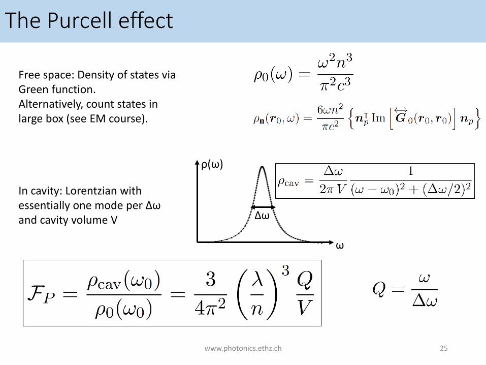
The Purcell effect
Free space: Density of states via Green function.Alternatively, count states in large box (see EM course).
In cavity: Lorentzian with essentially one mode per Δωand cavity volume V
ω
ρ(ω)
Δω
www.photonics.ethz.ch 25

The Purcell effect
The Purcell factor is the maximum rate enhancement provided by a cavity given that the source is1. Located at the field maximum of the mode2. Spectrally matched exactly to the mode3. Oriented along the field direction of the mode
Caution: Purcell factor is only defined for a cavity. The concept of the LDOS is much more general and holds for any photonic system.
www.photonics.ethz.ch 26

www.photonics.ethz.ch 28

www.photonics.ethz.ch 29

Micro-cavities in the 21st century
www.photonics.ethz.ch 30
Vahala, Nature 424, 839
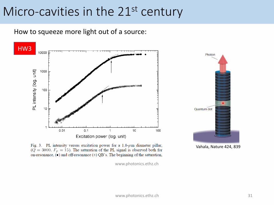
Micro-cavities in the 21st centuryHow to squeeze more light out of a source:
www.photonics.ethz.ch 31
www.photonics.ethz.ch
Vahala, Nature 424, 839
HW3
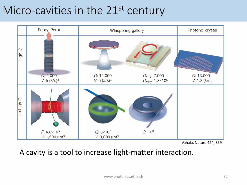
Micro-cavities in the 21st century
A cavity is a tool to increase light-matter interaction.
www.photonics.ethz.ch 32
Vahala, Nature 424, 839


![On the menu today - Photonics · On the menu today Light sources ... How many modes in frequency band [w, w+Dw] and resonator volume V? In free space ... Repeat experiment many times](https://img.pdfslide.net/doc/110x75/5ad9f81e7f8b9add658bfa83/on-the-menu-today-photonics-the-menu-today-light-sources-how-many-modes-in.jpg)