Embed Size (px)
Citation preview

Ahmed and Menon Robot. Biomim. (2015) 2:6 DOI 10.1186/s40638-015-0030-y
RESEARCH
On the static structural design of climbing robots: part 1Ausama Hadi Ahmed and Carlo Menon*
Abstract
This manuscript is the first of two parts of a work investigating optimal configurations of legged climbing robots while loitering on vertical surfaces. In this part 1, a mathematical model of a climbing robot based on the finite ele-ment method (FEM), specifically the stiffness method, is generated. A number of parameters, namely the height of the robot, the length of its body and the position of its legs, are investigated to assess their effect on the adhesion requirements needed for the robot to stay attached to a wall. Predictions of the developed mathematical model are validated using FEM commercial software. The body and the legs are assumed to be perpendicular to each other in this part 1. The effect of their inclination is investigated in the subsequent part 2 of our work. In part 2, the model is also used to predict postures that ants have while standing on vertical surfaces. The model is validated by comparing the predicted results to images of loitering ants. The parameters investigated provide guidelines to design legged climbing robots.
Keywords: Climbing robot, Geometry design, FEM
© 2015 Ahmed and Menon. This article is distributed under the terms of the Creative Commons Attribution 4.0 International License (http://creativecommons.org/licenses/by/4.0/), which permits unrestricted use, distribution, and reproduction in any medium, provided you give appropriate credit to the original author(s) and the source, provide a link to the Creative Commons license, and indicate if changes were made.
BackgroundA variety of legged robots having different size and design have been proposed in the literature to climb vertical surfaces. Such robots have different locomotion systems including tracks [1–3], wheels [4, 5], and legs [6, 7]. Legged robots, which are of primary interest for this work, use a variety of mechanisms to adhere to climbing surfaces, including magnets [8], dry adhesion, in the form of single layer [9, 10] or hierarchical [11], spines/claws [12–15], and negative pressure [16].
The design of some climbing robots was inspired by nature’s living organisms including geckos [7], spiders [6], cockroaches [12] or a combination of different spe-cies such as geckos and cockroaches [17]. The arrange-ment and inclination of the legs are not the same among the different designs of the robots. In fact, some of the robots, including Spinybot II [15], had their legs inclined forward; others, including Abigaille III [11] and ROBUG II [8], have some of their legs inclined forward and some backward; some others, including the RiSE and DIGbot
[12, 18], have their legs on the sides of their bodies, and others, including Abigaille II [6], have legs symmetrically distributed around their bodies.
In this work, the size and the configuration of legged climbing robots are analyzed by investigating the effect that different design parameters have on the maximum attachment force required by the robot to stay attached to a vertical surface. This work investigates the design of six-legged robots. They are analyzed in a 2-D space by taking into account the geometrical symmetries hexa-pods generally have. The finite element method (FEM) is used to analyze the force distribution on the tips of the robotic legs; FEM is selected as it provides more accurate results than approximated quasi-static methods generally used to investigate this problem [1, 6, 9–11, 19–21]. In this work, dimensionless parameters are selected as the beams used in the structures investigated in this work are scalable as long as the second moment of inertia is fixed.
The amount of force available to the robot to adhere to a vertical surface is critical regardless of the type of attachment mechanism (e.g., dry adhesion, suction, mag-nets) used to climb. A successful climbing robot should, in fact, always have enough force to be able to adhere to the wall. In this work, the optimal structure of the
Open Access
*Correspondence: [email protected] MENRVA Research Group, School of Engineering Science, Simon Fraser University, Burnaby, BC V5A 1S6, Canada

Page 2 of 11Ahmed and Menon Robot. Biomim. (2015) 2:6
robot is considered to be the one that requires the least attachment force to adhere to a vertical wall. This opti-mal structure would maximize the safety factor to avoid detachment or equivalently minimize the adhesion strength required by the adhesive pads or grasping mech-anisms used by the robot to adhere to a vertical surface. The formulation developed in this work is, therefore, general and is suitable to model legged robots relying on a large variety of different sources of adhesion.
This manuscript is organized as follows: “Kinematics” section presents the model and the kinematics of the examined multi-legged structure; “Structural analysis” section describes the proposed method to analyze the force distribution of the robot; “Investigated parameters” section presents results obtained by changing the dif-ferent geometrical parameters of the considered struc-ture on the force distribution on the tips of the robot’s legs. Conclusions and recommendations for the design of climbing legged robots are drawn at the end of the manuscript.
KinematicsHexapod robots such as Digbot [12], Abigaille II [6] and Abigaille III [3] generally have an axis of symmetry par-allel to the forward walking direction, shown in Fig. 1. Such robots can be simplified and studied in 2-dimen-sions, because the left and the right parts of the robots are symmetric.
In this work, the robot is considered to be loitering, as it is attached to the vertical surface. In this configuration, the motors of a robot would exert a constant torque on their legs to keep them in place and avoid detachment. From a quasi-static analysis perspective, each leg can, therefore, be considered as a part of a rigid structure. To simplify the analysis and draw conclusions that could be generalized to most six-legged robots, each robotic leg was arbitrarily simplified to be a straight equivalent beam, with stiffness approximately equal to that of the robotic leg. To account for the different possible values of stiffness that different robots or different leg’s configurations could have, we varied the cross-sectional area of the equivalent beam. A similar consideration was done for the body of the robot, which was also modeled with a straight beam and whose stiffness was changed by changing its cross-sectional area. By considering the legs and body weightless and assuming the mass of the robot to be concentrated at its centre of mass (CoM), which is consistent with the existing litera-ture [6, 9–11, 21–25], the variation of the cross-sectional area did not affect the weight of the robot and a compara-tive analysis was, therefore, possible. It should be noted that the effect of taking the weight of the legs into account without changing the overall weight of the robot would only slightly affect the shear and normal force distribution in the feet. Specifically, the shear forces would be more evenly distributed among the legs. The normal forces on the feet would instead slightly decrease, given the center of mass of the robot would be closer to the surface. In this work, the weight of the robot is assumed to be equal to one unit in all of the performed calculations in order to conveniently represent the forces on the tips of the feet as a percentage of the applied load. This normalization is used to generalize the results obtained in this work to a large variety of robots having different values of weight and dimensions. Figure 2 shows the simplified equivalent model that was considered. It should be noted that the legs of the robot were assumed to not transfer moment to the vertical surface, as commonly done in the literature [6, 9–11, 21, 24–27].
It should be noted that while this article specifically addresses robots in a static configuration, results of this work could be generalized to a certain extent to dynamic systems, as inertial forces resulting from accelerations of the robot would simply add to the weight of the robot, without affecting the optimal geometries investigated in this work. Variation of posture during walking is not addressed in this work as it resides outside the scope of this study.
Structural analysisThe robotic structure presented in “Kinematics” sec-tion is analyzed using the stiffness method [28], which Fig. 1 Abigaille III [3] walking upward of a surface

Page 3 of 11Ahmed and Menon Robot. Biomim. (2015) 2:6
uses the beams’ stiffness relations to compute the forces and the displacements of the structure. The overall rela-tionship between the forces applied to the structure (axial loads, shear loads and bending moments) and the resulted displacements is given by
where K is the structural stiffness matrix, F is a vector representing both the known forces applied to the struc-ture and the unknown reaction forces of the nodes and D is a vector comprising the known and the unknown dis-placements of the nodes. Damping is not included as a static analysis is considered in this work.
The structure of the robot is divided into six separate beams, see Fig. 2. Specifically, each of the three legs, the connection between the hind leg and the center of mass, the connection between the center of mass and the mid-dle leg and the connection between the middle leg and the front leg are all considered to be separate beams. The case when the middle leg is located between the hind leg and the center of mass is also formed using six beams: specifically, the three legs, the connection between the hind leg and the middle leg, the connection between the middle leg and the center of mass and the connection between the center of mass and the front leg.
The known displacements are those of the constrained nodes, namely those of the hinges (Hh,Hm,Hf) in x and y axes (see Fig. 2), are equal to zero. The unknown degrees of freedom are the distance the unconstrained nodes moved after applying the known forces on the structure; from Fig. 2, the unknown degrees of freedom are the lin-ear movement of nodes 1, 2, 3 and 4, and the rotation movement of all of the nodes, namely nodes 1–7. The known forces are the weight of the robot at the center of mass, and the linear force components of all of the unconstrained nodes, namely nodes 1–4 along with the
(1)F = KD
moment on all of the nodes, namely nodes 1–7, are equal to zero. The unknown forces are the reaction forces at the hinges, namely Fhx, Fhy, Fmx, Fmy, Ffx and Ffy, which are shown in Fig. 2. Equation (1) can, therefore, be written as:
where Fk is the vector of the known forces, Fu is the vector of the unknown forces, Du is the vector of the unknown displacements and Dk is the vector of the con-strained displacements.
From Eq. (2), the unknown displacements Du can be calculated as follows:
The unknown forces that are the reaction forces between the tips of the legs and the climbing surface are calcu-lated using
Substituting Eq. (3) into Eq. (4) yields:
The known distances Dk are the displacements of the constrained nodes which are equal to zero; as such, the above equation can be rewritten as:
Equation (6) is a closed form equation to calculate the reaction forces. Such an equation is implemented on a code developed in MATLAB environment. It should be noted that the force distribution depends on the stiffness of each beam relative to the other beams and not to the absolute stiffness value of each beam (see “Appendix”). Therefore, the results obtained in this
(2)
[
Fk
Fu
]
=
[
K 11 K 12
K 21 K 22
][
Du
Dk
]
(3)Du = K−111 · Fk − K
−111 · K 12 ·Dk
(4)Fu = K 21 ·Du + K 22 ·Dk
(5)Fu = K 21 ·
[
K−111 · Fk − K 12 ·Dk
]
+ K 22 ·Dk
(6)Fu = K 21 · K−111 · Fk
Fig. 2 The 2D simplified model of Abigaille III [11]

Page 4 of 11Ahmed and Menon Robot. Biomim. (2015) 2:6
work can be generalized to robots having any material and stiffness.
Commercially available finite element method (FEM) software, i.e., ANSYS (V14.0), is used to verify the cor-rect implementation of the stiffness method. Specifi-cally, the beam element BEAM188 based on Timoshenko beam theory is used to analyze 2D structures [29]. The MATLAB code is tested against the ANSYS software by comparing randomly selected cases solved using MAT-LAB with the same cases solved using ANSYS.
Investigated parametersThe FEM presented in “Structural analysis” is used in this section to minimize the normal adhesion required by the robot to stay attached to a vertical surface, i.e., Fhy, Fmy and Ffy in Fig. 2. The normal force is investigated by examining different parameters of the structure with the assumption that the legs are always perpendicu-lar and the body is parallel to the climbing surface. The investigated parameters are: (1) the position of the mid-dle leg; (2) the body height to body length aspect ratio; (3) the cross-sectional area of the beams forming the body and the legs. These three parameters are investi-gated in the following sections in pairs. Specifically, first the parameters 1 and 2 are investigated while parame-ter 3 is fixed; subsequently, the parameters 1 and 3 are investigated while parameter 2 is fixed. The combined effect of the three parameters is generalized in a later section.
Effect of height to length ratio and middle leg’s positionThis section describes the effect of changing the body height to body length aspect ratio and the effect of the position of the middle leg on the adhesion force
requirement on the tips of the legs. For the robot shown in Fig. 2, df is the distance between the middle and the front legs, dr is the distance between the middle and the hind legs and h is the height of the robot. The length of the body, df + dr, is arbitrarily chosen to be 200, while the radius of the beams is assumed to be the same and equals to two, and the height is in the 2.1–2000 range, which corresponds to a range of height to body length ratio of 0.0105–10. The obtained results are applicable to both bigger and smaller structures as long as the ratio of the height to the length is within the range and the radius is kept fixed. Distribution of the calculated normal force, representing the adhesion force requirement, for the change in the height to length aspect ratio and the position of the middle leg is shown in Fig. 3. Three different configurations are compared with ANSYS and plotted over the curve (see circles in Fig. 3) obtained using MATLAB. The average error between sim-ulations performed in MATLAB and ANSYS is 0.61 %.
The x axis in Fig. 3 represents the position of the mid-dle leg, where 0 means that the middle leg is positioned at the back of the robot. In this configuration, the mid-dle leg has the same position as the hind leg. The value of the x axis increases as the middle leg gets closer to the front leg and the value equals 1 when the middle and front legs have the same position. The y axis represents the height to length aspect ratio and the z axis represents the normal force per body weight. From Fig. 3, increas-ing the body height to body length ratio, on the x axis, requires higher force to keep the robot attached to the vertical surface because, a robot with higher height and fixed weight causes an increase in the torque applied to the robot’s structure due to gravity which needs higher forces on the tips of the legs to keep the robot in equilib-rium than that required by a robot with lower height.
Fig. 3 The required normal force at different height to length aspect ratio and different middle leg’s positions for a front leg, b middle leg and c hind leg. Circles represent simulations performed using ANSYS

Page 5 of 11Ahmed and Menon Robot. Biomim. (2015) 2:6
The normal force in Fig. 3 has two peaks located at middle leg positions of 0.07 and 0.93; the first peak is located at the hind leg with a maximum of 64.16 and the second is located at the middle leg with a maximum of 56.66. The peaks can be explained by analyzing the shear and normal forces distributions for a specific robotic structure with fixed height to length aspect ratio. The shear force distribution due to changing the middle leg’s position is explained first and the normal force distribu-tion resulting from changing the middle leg’s position is explained next.
Shear force distribution due to middle leg’s positionA structure with a height to body length aspect ratio of 1:2 is arbitrarily selected to explain the behavior of the normal force distribution due to changing the middle leg’s position. The shear force distribution on the legs of a robot with body length of 200, and height of 100 is shown in Fig. 4. The behavior of the force distribution for a three-legged robot is similar for different height to length ratios. The shear force distribution for the middle leg always has a peak at middle leg’s position of 0.5, while the front leg has a maximum at middle leg’s position of 0, and the hind leg has a maximum at middle leg’s position of 1. The normal force, in Fig. 3, for the middle leg has a minimum and a maximum at middle leg’s position value close to 0 and 1, respectively, the front leg has one peak close to middle leg’s position of 1 and the hind leg has one negative peak at a middle leg position of 0.
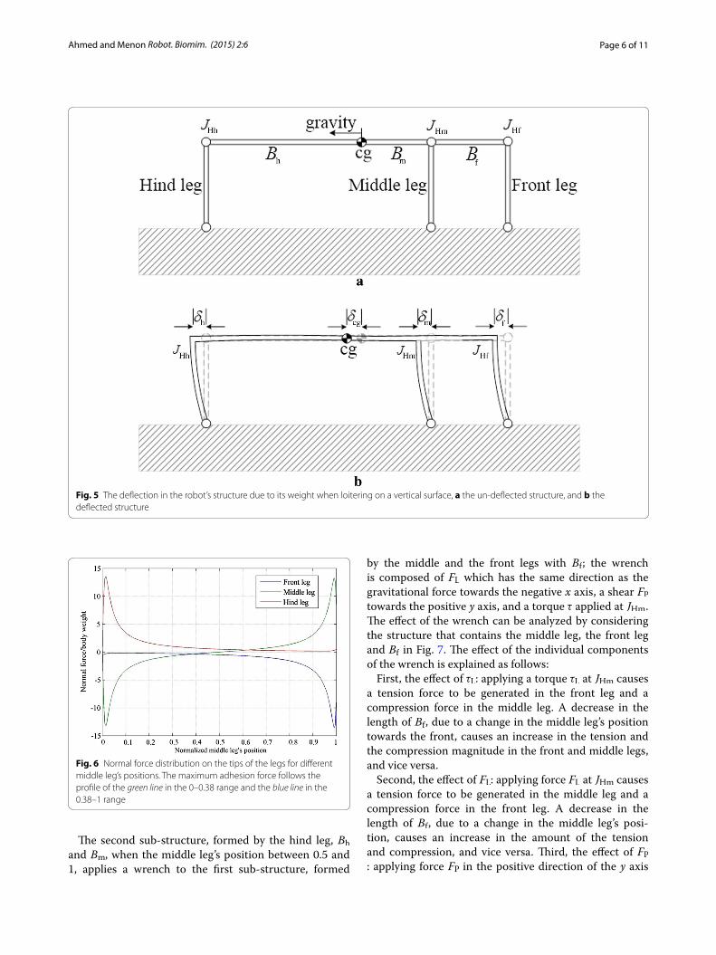
A rationale to understand the behavior shown in Fig. 4 is hereafter presented. Let us consider a robot on a verti-cal surface (see Fig. 5a). Due to the effect of its weight, the legs deflect backward and act as springs with equal spring constants. Therefore, the cg, the hip joints of the
front leg (JHf), the middle leg (JHm) and front leg (JHh) are displaced backward by a distance δcg, δf, δm and δh, respectively (see Fig. 5b). The induced shear forces on the tips of the legs are directly proportional to the displace-ments δh, δm and δf, because the legs are assumed to be identical to each other.
Figure 5, which is obtained through an ANSYS simula-tion, shows the deflections in the structure. In Fig. 5, Bm is the beam connecting JHm to cg. Bf and Bh are instead the beams connecting JHf to JHm and JHh to cg, respec-tively, when the middle leg is located between cg and JHf . These two parameters, that is Bf and Bh, are the beams connecting JHf to cg and JHh to JHm, respectively, when the middle leg is located between cg and JHh.
When the middle leg is located between the center of mass and the front leg, the body’s deflection creates a compression in Bm and Bf and an expansion in Bh, thus causing the distances δf, δm and δh to be less than δcg. The distance δh is equal to the compression in Bh subtracted from δcg; also, δm is equal to the elongation in Bm sub-tracted from δcg, and δf is equal to the compression in Bf subtracted from δm.
The maximum distance that JHm travels is when it is located at the center of mass cg , which corresponds to the maximum force it experiences. The expansion in Bf and the compression in Bh cause δf and δh to be less than δm; these expansion and compression generate less shear force in the hind and the front legs than that in the mid-dle one (see Fig. 4 when the middle leg’s position is at 0.5). The front and middle legs have the same shear force when the middle leg’s position is at 1, because δm and δf are equal. The amount of expansion in Bf increases with the length, causing δf to be smaller than δm and thus gen-erating less shear force in the front leg than that in the middle one (see Fig. 4 for a middle leg’s position ranging between 0.5 and 1).
The case when the middle leg is located between the center of mass and the hind leg could be analyzed as done previously. The main difference is that the beam Bm undergoes compression instead of expansion.
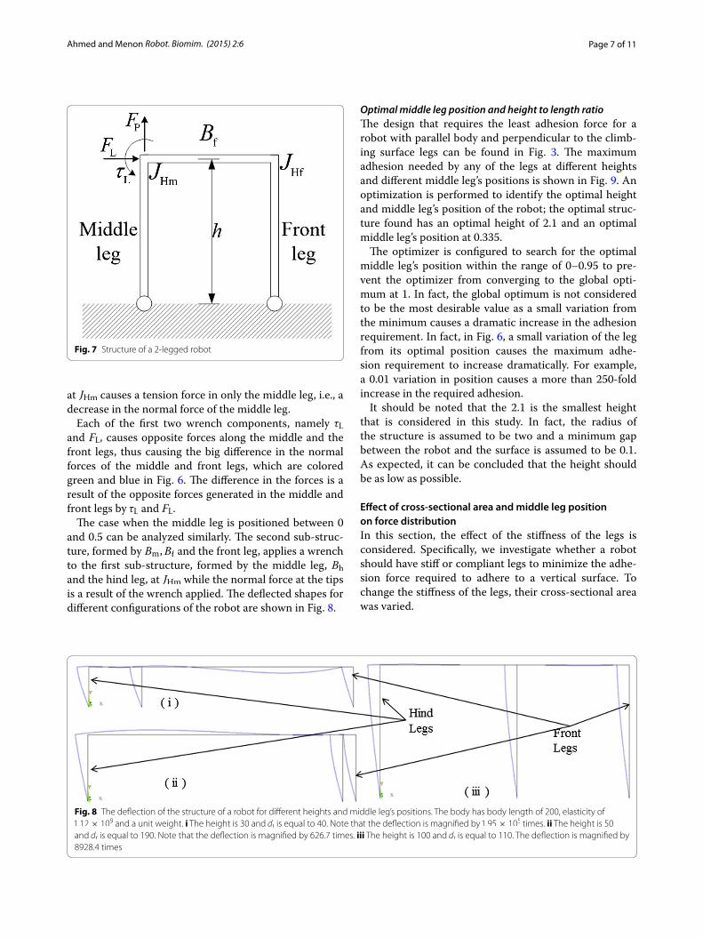
Normal force distribution due to middle leg’s positionThe normal force distribution at different middle leg’s positions is shown in Fig. 6. The distribution of the force on the tips of the legs can be explained by dividing the robot into two sub-structures at JHm. The first sub-struc-ture, when the middle leg’s position is located between 0.5 and 1, is composed of the middle leg, Bf and the front leg while the second sub-structure is composed of Bm, Bh and the hind leg. The first sub-structure, when the mid-dle leg is positioned between 0 and 0.5, is composed of the middle leg, Bh and the hind leg and the second sub-structure is composed of Bm, Bf and the front leg.
Fig. 4 Shear force distributions on the tips of the three legs for differ-ent positions of the middle leg
Page 6 of 11Ahmed and Menon Robot. Biomim. (2015) 2:6
The second sub-structure, formed by the hind leg, Bh and Bm, when the middle leg’s position between 0.5 and 1, applies a wrench to the first sub-structure, formed
by the middle and the front legs with Bf; the wrench is composed of FL which has the same direction as the gravitational force towards the negative x axis, a shear FP towards the positive y axis, and a torque τ applied at JHm . The effect of the wrench can be analyzed by considering the structure that contains the middle leg, the front leg and Bf in Fig. 7. The effect of the individual components of the wrench is explained as follows:
First, the effect of τL: applying a torque τL at JHm causes a tension force to be generated in the front leg and a compression force in the middle leg. A decrease in the length of Bf, due to a change in the middle leg’s position towards the front, causes an increase in the tension and the compression magnitude in the front and middle legs, and vice versa.
Second, the effect of FL: applying force FL at JHm causes a tension force to be generated in the middle leg and a compression force in the front leg. A decrease in the length of Bf, due to a change in the middle leg’s posi-tion, causes an increase in the amount of the tension and compression, and vice versa. Third, the effect of FP: applying force FP in the positive direction of the y axis
Fig. 5 The deflection in the robot’s structure due to its weight when loitering on a vertical surface, a the un-deflected structure, and b the deflected structure
Fig. 6 Normal force distribution on the tips of the legs for different middle leg’s positions. The maximum adhesion force follows the profile of the green line in the 0–0.38 range and the blue line in the 0.38–1 range
Page 7 of 11Ahmed and Menon Robot. Biomim. (2015) 2:6
at JHm causes a tension force in only the middle leg, i.e., a decrease in the normal force of the middle leg.
Each of the first two wrench components, namely τL and FL, causes opposite forces along the middle and the front legs, thus causing the big difference in the normal forces of the middle and front legs, which are colored green and blue in Fig. 6. The difference in the forces is a result of the opposite forces generated in the middle and front legs by τL and FL.
The case when the middle leg is positioned between 0 and 0.5 can be analyzed similarly. The second sub-struc-ture, formed by Bm,Bf and the front leg, applies a wrench to the first sub-structure, formed by the middle leg, Bh and the hind leg, at JHm while the normal force at the tips is a result of the wrench applied. The deflected shapes for different configurations of the robot are shown in Fig. 8.
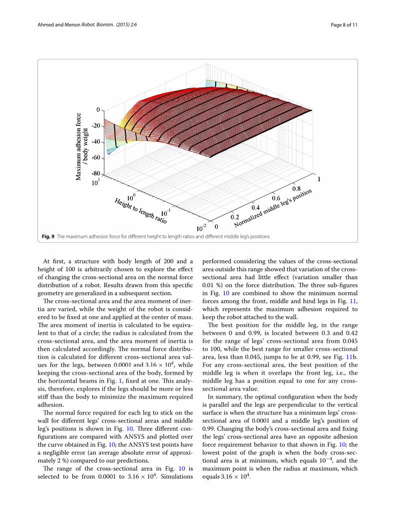
Optimal middle leg position and height to length ratioThe design that requires the least adhesion force for a robot with parallel body and perpendicular to the climb-ing surface legs can be found in Fig. 3. The maximum adhesion needed by any of the legs at different heights and different middle leg’s positions is shown in Fig. 9. An optimization is performed to identify the optimal height and middle leg’s position of the robot; the optimal struc-ture found has an optimal height of 2.1 and an optimal middle leg’s position at 0.335.
The optimizer is configured to search for the optimal middle leg’s position within the range of 0–0.95 to pre-vent the optimizer from converging to the global opti-mum at 1. In fact, the global optimum is not considered to be the most desirable value as a small variation from the minimum causes a dramatic increase in the adhesion requirement. In fact, in Fig. 6, a small variation of the leg from its optimal position causes the maximum adhe-sion requirement to increase dramatically. For example, a 0.01 variation in position causes a more than 250-fold increase in the required adhesion.
It should be noted that the 2.1 is the smallest height that is considered in this study. In fact, the radius of the structure is assumed to be two and a minimum gap between the robot and the surface is assumed to be 0.1. As expected, it can be concluded that the height should be as low as possible.
Effect of cross‑sectional area and middle leg position on force distributionIn this section, the effect of the stiffness of the legs is considered. Specifically, we investigate whether a robot should have stiff or compliant legs to minimize the adhe-sion force required to adhere to a vertical surface. To change the stiffness of the legs, their cross-sectional area was varied.
Fig. 7 Structure of a 2-legged robot
Fig. 8 The deflection of the structure of a robot for different heights and middle leg’s positions. The body has body length of 200, elasticity of 1.12× 10
9 and a unit weight. i The height is 30 and dr is equal to 40. Note that the deflection is magnified by 1.95× 10⁵ times. ii The height is 50
and dr is equal to 190. Note that the deflection is magnified by 626.7 times. iii The height is 100 and dr is equal to 110. The deflection is magnified by 8928.4 times
Page 8 of 11Ahmed and Menon Robot. Biomim. (2015) 2:6
At first, a structure with body length of 200 and a height of 100 is arbitrarily chosen to explore the effect of changing the cross-sectional area on the normal force distribution of a robot. Results drawn from this specific geometry are generalized in a subsequent section.
The cross-sectional area and the area moment of iner-tia are varied, while the weight of the robot is consid-ered to be fixed at one and applied at the center of mass. The area moment of inertia is calculated to be equiva-lent to that of a circle; the radius is calculated from the cross-sectional area, and the area moment of inertia is then calculated accordingly. The normal force distribu-tion is calculated for different cross-sectional area val-ues for the legs, between 0.0001 and 3.16× 10⁴, while keeping the cross-sectional area of the body, formed by the horizontal beams in Fig. 1, fixed at one. This analy-sis, therefore, explores if the legs should be more or less stiff than the body to minimize the maximum required adhesion.
The normal force required for each leg to stick on the wall for different legs’ cross-sectional areas and middle leg’s positions is shown in Fig. 10. Three different con-figurations are compared with ANSYS and plotted over the curve obtained in Fig. 10; the ANSYS test points have a negligible error (an average absolute error of approxi-mately 2 %) compared to our predictions.
The range of the cross-sectional area in Fig. 10 is selected to be from 0.0001 to 3.16× 10⁴. Simulations
performed considering the values of the cross-sectional area outside this range showed that variation of the cross-sectional area had little effect (variation smaller than 0.01 %) on the force distribution. The three sub-figures in Fig. 10 are combined to show the minimum normal forces among the front, middle and hind legs in Fig. 11, which represents the maximum adhesion required to keep the robot attached to the wall.
The best position for the middle leg, in the range between 0 and 0.99, is located between 0.3 and 0.42 for the range of legs’ cross-sectional area from 0.045 to 100, while the best range for smaller cross-sectional area, less than 0.045, jumps to be at 0.99, see Fig. 11b. For any cross-sectional area, the best position of the middle leg is when it overlaps the front leg, i.e., the middle leg has a position equal to one for any cross-sectional area value.
In summary, the optimal configuration when the body is parallel and the legs are perpendicular to the vertical surface is when the structure has a minimum legs’ cross-sectional area of 0.0001 and a middle leg’s position of 0.99. Changing the body’s cross-sectional area and fixing the legs’ cross-sectional area have an opposite adhesion force requirement behavior to that shown in Fig. 10; the lowest point of the graph is when the body cross-sec-tional area is at minimum, which equals 10−4, and the maximum point is when the radius at maximum, which equals 3.16× 10⁴.
Fig. 9 The maximum adhesion force for different height to length ratios and different middle leg’s positions

Page 9 of 11Ahmed and Menon Robot. Biomim. (2015) 2:6
Effect of middle leg position, height and legs’ cross‑sectional areaPrevious results can be generalized for robots with dif-ferent height to length ratios. In fact, an optimization is carried out to find the optimal middle leg position for different legs’ cross-sectional areas at different height to body length ratios, and the results are shown in Fig. 12. Similar to “Optimal middle leg position and height to length ratio” section, the optimizer is configured to search for the optimal middle leg’s position within the range of 0–0.95 to prevent the optimizer from converg-ing to the undesired global optimum at 1.
The best middle leg’s position for a range of height to length ratios, chosen arbitrarily between 0.01 and 10,
and different cross-sectional area between 0.0001 and 3.16× 10⁴ is bounded between 0.24 and 0.41. Figure 12 allows the designer to identify the optimal middle leg’s position for different legs’ cross-sectional areas at differ-ent height to length ratios.
In Fig. 12, the best configurations are the ones with the lowest height to length ratio and it is found that the best configuration at a specific height is the one with the high-est legs cross-sectional area value. In fact, the improve-ment in the adhesion for the entire cross-sectional areas investigated range, and the height to length ratios is calcu-lated to be between 22 and 71 %. For example, at the spe-cific height to length ratio of 1, arbitrarily chosen, the best adhesion requirement at the considered cross-sectional
Fig. 10 Normal forces required by the feet of the robot for different legs’ cross-sectional areas and different middle leg’s positions with the body’s cross-sectional area fixed at 1. Circles represent simulations performed using ANSYS
Fig. 11 A range of values of legs’ cross-sectional area and middle leg’s positions, a maximum adhesion force requirement, and b the maximum adhesion force within −0.5 and −0.1 of the maximum normal force/body weight

Page 10 of 11Ahmed and Menon Robot. Biomim. (2015) 2:6
areas sorted from best to worse is: [3.14 × 10⁴ 4.07 × 10³ 530.9 66.48 12.57 1.54 0.283 0.0314], where the first four cross-sectional areas have almost the same adhesion requirement value and the improvement in the adhesion force requirement between the cross-sectional area of 3.14 × 10⁴ and 0.0314 is calculated to be 29 %.
In part 2 of the paper, the posture of living ants loitering on a vertical surface is used to confirm the validity of the assumptions used in this paper. The authors simplified the ants’ structure in the same manner as in this part 1. The model proposed in this part 1 paper was used to predict the configuration of the ants’ posture and the effect of both their middle leg’s position and body’s cross-sectional area.
ConclusionIn this work, the effect of different geometrical parameters on the structure of a legged robot is investigated and ana-lyzed using the stiffness method. To improve the efficiency of vertical climbing, the height to length ratio of the robot should be kept as low as possible, the cross-sectional area of the legs should be as big as possible, and the middle leg should be positioned between 0.24 and 0.41. The pre-sented parametric study is utilized as an outline to assist designing the structure of climbing robots when loitering on a vertical surface. The presented results are applicable to any robot size as they are unit-less. Equation (6), which is at the foundation of the developed code, can potentially be implemented in a microcontroller to optimize in real time the posture of the robot. Results presented in this work yield the following guidelines to design climbing
robots: (1) height to length ratio should be as small as pos-sible; (2) the cross-sectional area of the structure should be as big as possible; and (3) the position of the middle leg can be selected from Fig. 12, which provides the optimal mid-dle leg’s position as a function of the height to length ratio and the cross-sectional area of the structure.
Authors’ contributionsBoth authors were equally involved in the study and preparation of the manu-script. Both authors read and approved the final manuscript.
AcknowledgementsThis work was supported by the Natural Sciences and Engineering Research Council of Canada (NSERC) and the Libyan Ministry of Higher Education. The authors thank the members of the Menrva Lab for their support.
Competing interestsThe authors declare that they have no competing interests.
AppendixIn this Appendix we show that the use of different mate-rials does not change the results of the geometrical opti-mization that is performed. In fact, the stiffness matrix for one beam is given by:
(A1)F =
AE
L0 0 −
AE
L0 0
012EI
L36EI
L20 −
12EI
L36EI
L2
06EI
L24EI
L0 −
6EI
L22EI
L
−AE
L0 0
AE
L0 0
0 −12EI
L3−
6EI
L20
12EI
L3−
6EI
L2
06EI
L22EI
L0 −
6EI
L24EI
L
·D
Fig. 12 The optimal position of the middle leg for different heights to length ratios and different cross-sectional area of the structure. Lower height to length ratio results in lower adhesion requirement, while higher cross-sectional area also results in lower adhesion requirement

Page 11 of 11Ahmed and Menon Robot. Biomim. (2015) 2:6
where E is the elasticity coefficient, A is the cross-sec-tional area of the beam, L is the length of the beam and I is the inertia of the beam. Assuming all of the cross sec-tions of the beams is a circle; the second moment of iner-tia for a circular cross section is:
Factoring out E, A and L can be written as:
K E is the stiffness matrix multiplied by LA·E
. In the same way, A·EL can be taken as a common factor from all of the elements of the stiffness matrix in Eq. (6), which can be rewritten as:
the above equation can be written as:
It can be seen that equation (A7) is independent of the elasticity coefficient E. In other words, the elastic-ity of the beams relative to each other is what causes the change in the force distribution.
Received: 5 August 2015 Accepted: 10 November 2015
References 1. Xu Z, Ma P. A wall-climbing robot for labelling scale of oil tank’s volume.
Robotica. 2002;20(02):209–12. 2. Shen W, Gu J, Shen Y. Permanent magnetic system design for the wall-
climbing robot. Appl Bionics Biomech. 2006;3(3):2078–83. 3. Cui G, Liang K, Guo J, Li H, Gu D. Design of a climbing robot based on
electrically controllable adhesion technology. In: International conference on solid state and materials Lecture Notes in Information Technology. 2012;22:90–5.
(A2)I =πr4
4=
Ar2
4
(A3)
F =A · E
L
1 0 0 −1 0 0
03r
2
L23r
2
2L0 −
3r2
L23r
2
2L
03r
2
2Lr2
0 −3r
2
2L
r2
2
−1 0 0 1 0 0
0 −3r
2
L2−
3r2
2L0
3r2
L2−
3r2
2L
03r
2
2L
r2
20 −
3r2
2Lr2
·D
(A4)F =
[
A · E
L· K E
]
·D
(A5)Fu =
[
A · E
L· K E21
]
·
[
A · E
L· K E11
]
−1
· Fk
(A6)Fu =A · E
L· K E21 ·
L
A · E· K
−1E11 · Fk
(A7)Fu = K E21 · K−1E11 · Fk
4. Shang J, Bridge B, Sattar T, Mondal S, Brenner A. Development of a climbing robot for inspection of long weld lines. Ind Robot Int J. 2008;35(3):217–23.
5. Morris W, Xiao J. City-climber: development of a novel wall-climbing robot. J Stud Res. 2008;1:40–5.
6. Li Y, Ahmed A, Sameoto D, Menon C. Abigaille II: toward the development of a spider-inspired climbing robot. Robotica. 2012;30(1):79–89.
7. Asbeck A, Dastoor S, Parness A, Fullerton L, Esparza N, Soto D, Heyneman B, Cutkosky M. Climbing rough vertical surfaces with hierarchical direc-tional adhesion. In: IEEE international conference robotics and automa-tion, p. 2675–2680; 2009.
8. Luk BL, Cooke DS, Galt S, Collie AA, Chen S. Intelligent legged climbing service robot for remote maintenance applications in hazardous environ-ments. Rob Auton Syst. 2005;53(2):142–52.
9. Murphy MP, Kute C, Menguc Y, Sitti M. Waalbot II: adhesion recovery and improved performance of a climbing robot using fibrillar adhesives. Int J Rob Res. 2010;30(1):118–33.
10. Daltorio KA, Wei TE, Horchler AD, Southard L, Wile GD, Quinn RD, Gorb SN, Ritzmann RE. Mini-Whegs TM Climbs steep surfaces using insect-inspired attachment mechanisms. Int J Rob Res. 2009;28(2):285–302.
11. Henrey M, Ahmed A, Boscariol P, Shannon L, Menon C. Abigaille-III: a ver-satile, bioinspired hexapod for scaling smooth vertical surfaces. J Bionic Eng. 2014;11(1):1–17.
12. Palmer III LR, Diller ED, Quinn RD. Design of a wall-climbing hexapod for advanced maneuvers. In: International conference on intelligent robots and systems; 2009.
13. Lam TL, Xu Y. A flexible tree climbing robot: Treebot—design and imple-mentation. In: IEEE international conference robotics automation, May 2011. p. 5849–54.
14. Haynes G, Rizzi A. Gait regulation and feedback on a robotic climbing hexapod. In: Proceedings of robotics: science and systems; 2006.
15. Asbeck AT, Cutkosky MR, Provancher WR. SpinybotII: climbing hard walls with compliant microspines. In: ICAR’05, Proceedings of 12th interna-tional conference on advanced robotics, 2005, p. 601–6.
16. Elkmann N, Felsch T, Sack M, Böhme T, Hortig J, Saenz J. Modular climbing robot for service-sector applications. Ind Robot Int J. 1999;26(6):460–5.
17. Spenko M, Haynes G, Saunders J, Cutkosky M, Rizzi A. Biologically inspired climbing with a hexapedal robot. J F Robot. 2008;25(4–5):223–42.
18. Saunders A, Goldman DI, Full RJ, Buehler M. The RiSE climbing robot : body and leg design. In: Proceedings of SPIE defence and security sym-posium, unmanned systems technology; 2006.
19. Krahn J, Liu Y, Sadeghi A, Menon C. A tailless timing belt climbing plat-form utilizing dry adhesives with mushroom caps. Smart Mater Struct. 2011;20(11):115021.
20. Unver O, Sitti M. Tankbot: a palm-size, tank-like climbing robot using soft elastomer adhesive treads. Int J Rob Res. 2010;29(14):1761–77.
21. Vidoni R, Gasparetto A. Efficient force distribution and leg posture for a bio-inspired spider robot. Rob Auton Syst. 2011;59(2):142–50.
22. Santos D, Heyneman B, Kim S, Esparza N, Cutkosky MR. Gecko-inspired climbing behaviors on vertical and overhanging surfaces. In: 2008 IEEE international conference in robotics automation; 2008. p. 1125–1131.
23. Liu J, Tong Z, Fu J, Wang D, Su Q, Zou J. A gecko inspired fluid driven climbing robot. In: 2011 IEEE international conference in robotics auto-mation; 2011. p. 783–8.
24. Murphy MP, Member S, Sitti M. Waalbot : an agile small-scale wall-climb-ing robot utilizing dry elastomer adhesives. IEEE/ASME Trans Mechatron. 2007;12(3):330–8.
25. Boscariol P, Henrey MA, Li Y, Menon C. Optimal gait for bioinspired climb-ing robots using dry adhesion: a quasi-static investigation. J Bionic Eng. 2013;10(1):1–11.
26. Hawkes EW, Ulmen J, Esparza N, Cutkosky MR. Scaling walls: applying dry adhesives to the real world. In: IEEE international conference in intelligent and robotic systems; 2011. p. 5100–6.
27. Gasparetto A, Vidoni R, Seidl T. Kinematic study of the spider system in a biomimetic perspective. In: 2008 IEEE/RSJ international conference in intelligent and robotic systems; 2008. p. 3077–82.
28. Russell H. Structural analysis. 8th ed. New Jersey: Pearson Education; 2012.
29. Rao SS. Mechanical vibrations. 2nd ed. Massachusetts: Addison-Wesley; 1990.