Embed Size (px)
Citation preview

Comput. Methods Appl. Mech. Engrg. 193 (2004) 4475–4492
www.elsevier.com/locate/cma
On the use of computational intelligence in the optimalshape control of functionally graded smart plates
K.M. Liew a,b,*, X.Q. He b, Tapabrata Ray c
a School of Mechanical and Production Engineering, Nanyang Technological University, Nanyang Avenue, 639798, Singaporeb Nanyang Centre for Supercomputing and Visualisation, Nanyang Technological University, Nanyang Avenue, 639798, Singapore
c Temasek Laboratories, National University of Singapore, 5 Sports Drive 2, 117508, Singapore
Received 15 July 2003; received in revised form 5 November 2003; accepted 19 February 2004
Abstract
Functionally graded material (FGM) plates are an essential component for most advanced integrated systems in
terms of vibration and acoustic controls or condition monitoring. In general, these FGM plates are designed with
embedded piezoelectric sensors and actuators to achieve their shape control. This optimal control problem is normally
required to find appropriate actuator voltage and displacement control gains that will generate the desired shape. Such
an optimal control problem is known to be highly non-linear and often posses slope and functional discontinuity that
will limit the efficiency of the gradient based methods. Stochastic, zero-order, population-based optimization methods
are ideal for solving this class of problems. In this paper, we introduce a stochastic, zero-order optimization algorithm
based on the principles of learning. This algorithm is embedded with three key learning strategies that control who to
learn from (i.e. leader identification and leader selection) and what to learn (i.e. information acquisition) to reach a
common goal. The leader identification mechanism partitions the individuals into a set of leaders and a set of followers.
The followers interact with the leaders and move toward the better performing leaders in searching for better solutions.
The parameter-free algorithm provides the designer with the true flexibility that is necessary to handle various forms of
design problem effectively and at a computational cost that is comparable to existing stochastic optimization methods.
In this study, numerical results are presented for the shape control of the FGM plates under a temperature gradient by
optimizing (i) the voltage distribution for the open loop control, and (ii) the displacement control gain values for the
closed loop feedback control. We also examine the effect of the constituent volume fractions of zirconia, through the
varying of volume fraction exponent n, on the optimal voltages and gain values.
� 2004 Elsevier B.V. All rights reserved.
Keywords: FGM; Optimal shape control; Computational intelligence; FEM; Smart plates
* Corresponding author. Address: Nanyang Centre for Supercomputing and Visualisation, School of Mechanical and Production
Engineering, Nanyang Technological University, Nanyang Avenue, 639798, Singapore. Tel.: +65-6790-4076; fax: +65-6793-6763.
E-mail address: [email protected] (K.M. Liew).
0045-7825/$ - see front matter � 2004 Elsevier B.V. All rights reserved.
doi:10.1016/j.cma.2004.02.016
4476 K.M. Liew et al. / Comput. Methods Appl. Mech. Engrg. 193 (2004) 4475–4492
1. Introduction
A smart functionally graded (FG) structure is constructed by integrating intelligent and active materials,
such as piezoceramics, in a host structure within which material properties vary continuously and inho-
mogeneously. FG structures contain different compositional concentrations of a desirable second phase
material leading to smooth and continuous spatial variations of the properties across its thickness. They
were first developed by the Japanese in the late 1980s, and since then this class of materials have attracted a
number of investigators (see [1–4]). In general, functionally graded materials (FGMs) are made from amixture of ceramics and metals. The ceramic constituents of the FGMs are able to withstand high tem-
perature environments due to their better thermal resistance characteristics, while the metal constituents
provide stronger mechanical performance and reduce the possibility of catastrophic fracture.
Embedding a network of piezoceramic actuators and sensors within the FG structure creates a self-
controlling and self-monitoring smart system. This newly engineered class of materials has resulted in
significant improvements in the performance of integrated systems, actuation technologies, shape control,
vibration and acoustic control, and condition monitoring.
Many researchers have recently focused their attention on the use of piezoelectric materials as sensorsand actuators for the active control of structures. Most of the effort, however, has been directed toward the
vibration control of structures. Examples of these include the exact analytical solution provided by Rivory
et al. [5] for the dynamic response of a simply-supported beam excited by a pair of out of phase piezoelectric
actuators, by Chen et al. [6] for laminated cylindrical shells with piezoelectric layers, by Reddy [7] for the
Navier solution of laminated composite plates with integrated sensors and actuators, and by Liew et al. [8]
for the mesh-free solution of the active control of composite beams and plates with piezoelectric layers
under different dynamic loading conditions. Finite element models have been proposed by Allik and
Hughes [9], Lammering [10], Hwang et al. [11], Liew et al. [12–15], and He et al. [16,17] for the dynamicanalysis and control of more complicated structures, such as laminate beams, plates and shells with pie-
zoelectric patches, and functionally graded plates and shells that are subjected to thermal loading. In these
studies, the third-order theory of Reddy, the classical laminate plate theory (CLPT), first-order shear
deformation theory (FSDT), and layerwise laminate theory have been presented for thin and moderately
thick plates and shells. Various control algorithms, based on the direct feedback of displacement, velocity,
and acceleration, have been applied, and various controllers, such as the Linear Quadratic Gaussian with
Loop Transfer Recovery (LQG/LTR), the Independent Modal Space Control (IMSC), and the neural
network controllers, were designed for the effective control of vibration.In contrast to vibration control, less work has been carried out on the shape control of structures.
Koconis et al. [18] first investigated the shape control of composite plates and shells with embedded
actuators. They carried out the bending analysis of composite beams, plates, and shells using the Rayleigh–
Ritz method to determine the voltages that are needed to achieve a specified desired shape. Their method
was formulated on the basis of mathematical models using two-dimensional, linear, shallow shell theory
including transverse shear effects. Chandrashekhara and Varadarajan [19] developed finite element model
for the adaptive shape control of composite beams. They based the finite element model on a higher-order
shear deformation theory and accounts for lateral strains, and implemented a constrained optimizationalgorithm to obtain the desired shape of beams. Wang et al. [20] derived analytical expressions and opti-
mality conditions for determining the input voltages to be applied to the piezoelectric actuators to bend the
beam to the desired shape. The obtained optimal voltages for various beam problems serve as benchmarks
for the validity, convergence, and accuracy of numerical results from other numerical methods. Tong et al.
[21] presented analytical models and solutions for the shape control of composite thin plates with piezo-
electric actuators. Ribeiro et al. [22] applied the Genetic Algorithm (GA) for the optimal design and control
of beams and plates. The finite element method was used for the analysis of the bending and vibration
analysis of beams and plates. Only input voltages were considered as variables. Feedback control gains

K.M. Liew et al. / Comput. Methods Appl. Mech. Engrg. 193 (2004) 4475–4492 4477
were neglected for the shape control of structures, and a simple example of the shape control of a beam waspresented.
In this study, we solve various forms of the optimal shape control problem using an optimization
algorithm that is based on computational intelligence (CI). The optimal values of actuator input voltages
for the open loop shape control and the feedback control gains for the closed loop shape control are
obtained via optimization to achieve a desired shape. It is worth noting that a closed loop shape control of
structures was first carried out by optimizing the values of the displacement control gain. This paper ex-
tends the authors’ earlier work on smart structures in which the actuator voltages or gain values were
obtained for the effective control of deflection or vibration (see [16,17,23]). These works on smart structuresare only suitable for simple cases, such as the deflection or vibration control of plates with piezoelectric
layers. For more complex problems, such as the shape control of plates with piezoelectric patches, it is very
difficult to obtain the optimal values of actuator voltages or gain values of the piezoelectric patches to
control the plate to a desired shape using the earlier methods. However, using the current algorithm based
on CI we overcome the earlier difficulties. The strength of the algorithm lies with its flexibility in handling
various forms of the design problem. Although both of the problems that are solved in this paper using CI
are single objective unconstrained problems, the complete algorithm that is presented is capable of handling
unconstrained and constrained single and multi-objective formulations of the problem. The details of thealgorithm and the formulations of the optimal shape control problem are presented in subsequent sections.
2. Algorithm based on computational intelligence
Our interest in developing an algorithm based on learning originated from the empirical observations
that were reported by Shi and Eberhart [24] on the performance of their particle swarm algorithm (PSO).
They observed that the PSO performance was rather insensitive to the initial swarm size, and it exhibited afast convergence capability. These two PSO features are attractive because we intend to solve problems in
which function evaluations are computationally expensive.
The algorithm that we present in this paper is based on a leader–follower information exchange
mechanism, in which individuals learn from the better performers. To partition the individuals into a set of
leaders and a set of followers, a measure of fitness is required. Although it is easy to assign fitness values to
individuals in unconstrained problems, the assignment is non-trivial for constrained problems, as it requires
means to compare infeasible solutions. Existing methods of comparison use different forms (sum of con-
straint violations, sum of scaled constraint violations, amount of largest constraint violation, weighted andscaled combinations of the above, or adaptive weights and scaling factors) to assign fitness values to
infeasible individuals. Such methods of fitness assignment are computationally simple, but often require
additional inputs for scaling and aggregation or intrinsically define fitness measures that may not be
desirable.
The algorithm introduced in this paper is built upon the following generic notions.
• It drives the set of solutions toward feasibility before trying to improve an infeasible individual’s objec-
tive function value.• A feasible solution is preferred to an infeasible solution.
• Between two feasible solutions, that with a better objective function value is preferred to the other.
• Between two infeasible solutions, that with a lower non-dominated rank based on the constraint matrix
is preferred to the other.
Ray et al. [25] first proposed the use of the non-dominated rank of an individual to compare infeasible
solutions. The Non-Dominated Sorting Genetic Algorithm (NSGA) that Srinivas and Deb [26] introduced

4478 K.M. Liew et al. / Comput. Methods Appl. Mech. Engrg. 193 (2004) 4475–4492
was used to rank individuals based on the constraint matrix. Subsequently, Ray et al. [27–29] developedevolutionary algorithm (EA) and swarms, and successfully applied them to various engineering design
optimization problems. Although the process of non-dominated sorting based on a constraint matrix is
computationally expensive, it certainly eliminates the need for scaling and weighting factors, which are
otherwise required to derive a single scalar measure of fitness. The details of the algorithm are explained in
the context of a multi-objective constrained minimization problem. A multi-objective constrained mini-
mization problem can be presented as follows:
Minimize F ¼ ½ f1ðxÞ f2ðxÞ � � � fP ðxÞ � ð1Þsubject to giðxÞP ai; i ¼ 1; 2; . . . ; q; ð2Þ
hjðxÞ ¼ bj; j ¼ 1; 2; . . . ; r; ð3Þ
where there are P objectives, q inequality and r equality constraints, and x ¼ ½ x1 x2 � � � xn � is the vectorof n design variables. To handle the equality constraints, each is replaced by a pair of inequalities of the
form hjðxÞ6 bj þ d and hjðxÞP bj � d. Thus, r equality constraints lead to 2r inequalities, and the total
number of inequalities for the problem is denoted by s ¼ qþ 2r. For the individual, c denotes the constraintsatisfaction vector, i.e. c ¼ ½ c1 c2 � � � cs �, where ci > 0 indicates the violation of the ith constraint. The
‘‘Constraint’’ matrix for a set of M individuals assumes the following form
Constraint ¼
c11 c12 � � � c1sc21 c22 � � � c2s... ..
. . .. ..
.
cM1 cM2 cMs
26664
37775: ð4Þ
The ‘‘Objective’’ matrix for a set of M individuals assumes the following form
Objective ¼
f11 f12 � � � f1Pf21 f22 � � � f2P... ..
. . .. ..
.
fM1 fM2 fMP
26664
37775: ð5Þ
The non-dominated sorting is used to rank the individuals based on the ‘‘Constraint’’ matrix and the
‘‘Objective’’ matrix. A linear expression of fitness is used in this study, where the fitness of the ith individual
is presented as follows:
fitnessi ¼ 1þMaxRank�RankðiÞ: ð6ÞIt can be observed from the ‘‘Constraint’’ matrix that when all of the individuals are infeasible, the
Rank¼ 1 solutions based on the ‘‘Constraint’’ matrix are the best in terms of minimal constraint violation.
Whenever there are one or more feasible individuals within the set, the feasible solutions assume the
Constraint Rank¼ 1.
2.1. The pseudo code
Initialize a set of solutions {S} with M individuals using a Uniform Random Generator and the Variable
Bounds;
Do {
Leader Identification
Compute Objective value and Constraint Satisfaction Vector for each Individual in {S};

K.M. Liew et al. / Comput. Methods Appl. Mech. Engrg. 193 (2004) 4475–4492 4479
Sort and Rank the Individuals of {S} based on their Objective Function values using Non-Dominated
Sorting;
Sort and Rank the Individuals of {S} based on their Constraint Satisfaction Vector using Non-Domi-
nated Sorting;
Compute the Average Objective and Average Constraint Rank;
Count the Number of Feasible Individuals;
Assign Individuals with Objective Rank<Average Objective Rank to Set {A};Assign Individuals with Constraint Rank<Average Constraint Rank to Set {B};Assign Feasible Individuals as Set {C};Compute A \ B and A \ C;If (Size of Set C ¼ 0): Assign Individuals with Rank Constraint¼ 1 to Set of Leaders {L};If (Size of Set C > M=2) and (Size of A \ C > 0): Assign Individuals A \ C to Set of Leaders {L};If (Size of Set C > M=2) and (Size of A \ C ¼ 0): Assign Individuals of C to Set of Leaders {L};If (Size of Set C5M=2) and (Size of C > 0): Assign Individuals of C to Set of Leaders {L};Assign Individuals of {S} that are not members of {L} to the Set of Followers {F };Sort and Rank the Individuals of Set {L} based on their Objective Function value using Non-DominatedSorting;
Sort and Rank the Individuals of Set {L} based on their Constraint Satisfaction Vector using Non-Dom-
inated Sorting;
Copy the Set of Leaders {L};Do {
Leader Selection
If (Size of C ¼ 0): Select a Leader from {L} using Roulette Wheel based on Constraint Rank of the
Individuals of Set {L}.If (Size of C 6¼ 0): Select a Leader from {L} using Roulette Wheel based on Objective Rank of the
Individuals of Set {L}.Information Acquisition
Move the follower using a leader centric exploration operator that will be discussed in Section 2.4.
} while Every Follower has not Moved or Termination Condition¼False;
} while (termination condition¼False)
The pseudo code of the information acquisition operator is as follows:
Select the leader and assign it as P ;Scale the variables between 0 and 1 based on the population.
Compute the Euclidian distance (D) between the follower and the leader in the parametric space;
For i ¼ 1 to Number of Variables
Generate a random number (R) using a Gaussian distribution with l ¼ 0 and r ¼ 1;
CðiÞ ¼ P ðiÞ þ R � D;Transform the variables back to original scale.
2.2. Leader identification
It can be observed from the pseudo code that the leader identification process is the most computa-
tionally expensive step in the algorithm. It involves a non-dominated sorting that is based on the ‘‘Con-
straint’’ matrix and the ‘‘Objective’’ matrix. The criterion of leader identification is both relative and
adaptive because it changes depending upon the overall performance of the set of solutions. A schematic
interpretation of leaders under various scenarios is presented in Fig. 1. If the set of individuals assumes the

Fig. 1. Schematic interpretation of leaders. (a) Leaders are Constraint Rank¼ 1; (b) leaders are fAg \ fBg; (c) leaders are all feasiblesolutions fCg; (d) leaders are fAg \ fCg.
Fig. 2. Sampled points with leader ð0:75; 0:75Þ and two different locations of followers: (a) follower ð0:70; 0:70Þ, (b) follower
ð0:50; 0:50Þ.
4480 K.M. Liew et al. / Comput. Methods Appl. Mech. Engrg. 193 (2004) 4475–4492
forms that are shown in Fig. 1(a) or 1(b) where there are no feasible solutions, the leaders are those withconstraint Rank¼ 1. In the presence of feasible solutions, the leaders are either all of the feasible indi-
viduals, as in Fig. 1(c), or the intersection of the set of feasible individuals and the set of good objective
performers, as in Fig. 1(d). The process of separately handling constraints and objectives using non-
dominated ranks and the use of two fitness measures, instead of a single fitness measure, eliminates the
problem of scaling and aggregation. The identification of the right leaders is important, as it means sub-
sequent exploration around their neighborhoods.
2.3. Leader selection
At every time instant, the set of individuals are partitioned into a set of leaders and a set of followers.
Because the leaders do not move, maintaining them at their original location ensures elitism. Each follower
selects a leader and moves to a new location after acquiring information from the leader. The selection of a
leader is based on a roulette wheel mechanism which ensures that better performing leaders have a greater
chance of information sharing with the followers. This leader selection process assumes that every follower
has the performance information of all the leaders in order to make an informed choice, unlike a real
swarm, in which an individual has access to neighborhood information only.
2.4. Information acquisition
This is the third key element in the algorithm. Once a follower has identified a leader, it acquires
information from the leader and decides on its next move. The information acquisition mechanism is
analogous to crossover operators in genetic and evolutionary paradigms, which is meant to inherit the
K.M. Liew et al. / Comput. Methods Appl. Mech. Engrg. 193 (2004) 4475–4492 4481
meaningful properties of the parents. From the pseudo code presented earlier, one can observe that theoperator explores neighborhoods of the leader, as is schematically presented in Fig. 2. It can be observed
from Fig. 2(a) and (b) that a larger separation between the leader and the follower results in a greater
exploration of the design space, while a small separation between the leader and the follower results in a
more focused neighborhood search around the leader.
3. Model formulation
3.1. Current control model
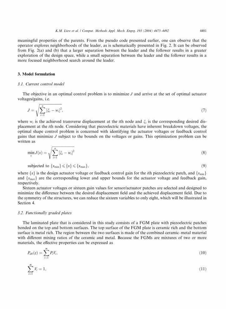
The objective in an optimal control problem is to minimize J and arrive at the set of optimal actuator
voltages/gains, i.e.
J ¼ffiffiffiffiffiffiffiffiffiffiffiffiffiffiffiffiffiffiffiffiffiffiffiffiffiffiXn
i¼1
½ni � wi�2s
; ð7Þ
where wi is the achieved transverse displacement at the ith node and ni is the corresponding desired dis-
placement at the ith node. Considering that piezoelectric materials have inherent breakdown voltages, the
optimal shape control problem is concerned with identifying the actuator voltages or feedback control
gains that minimize J subject to the bounds on the voltages or gains. This optimization problem can be
written as
minx
JðxÞ ¼ffiffiffiffiffiffiffiffiffiffiffiffiffiffiffiffiffiffiffiffiffiffiffiffiffiffiXn
i¼1
½ni � wi�2s
ð8Þ
subjected to fxming6 fxg6 fxmaxg; ð9Þwhere fxg is the design actuator voltage or feedback control gain for the ith piezoelectric patch, and fxmingand fxmaxg are the corresponding lower and upper bounds for the actuator voltage and feedback gain,
respectively.
Sixteen actuator voltages or sixteen gain values for sensor/actuator patches are selected and designed to
minimize the difference between the desired displacement field and the achieved displacement field. Due to
the symmetry of the structures, we can reduce the sixteen variables to only eight, which will be illustrated in
Section 4.
3.2. Functionally graded plates
The laminated plate that is considered in this study consists of a FGM plate with piezoelectric patches
bonded on the top and bottom surfaces. The top surface of the FGM plate is ceramic rich and the bottom
surface is metal rich. The region between the two surfaces is made of the combined ceramic–metal material
with different mixing ratios of the ceramic and metal. Because the FGMs are mixtures of two or more
materials, the effective properties can be expressed as
PeffðzÞ ¼Xmi¼1
PiVi ; ð10Þ
Xmi¼1
Vi ¼ 1; ð11Þ

4482 K.M. Liew et al. / Comput. Methods Appl. Mech. Engrg. 193 (2004) 4475–4492
where Peff is the effective material property of the FGM, and Pi and Vi respectively are the property and
volume fraction of the constituent material i of the FGM. The volume fraction can be written as
Vi ¼2zþ h2h
� �n
; � h26 z6
h2; ð12Þ
where n is the volume fraction exponent ð06 n61Þ, h is the thickness of the plate, and z is the coordinatein the thickness direction. The functionally graded material consists of two constituent materials, ceramic
and metal, so the material properties can be expressed as
cijðzÞ ¼ ccij�
� cmij� 2zþ h
2h
� �n
þ cmij ; ð13Þ
where ccij and cmij are the corresponding material properties of the ceramic and metal.
3.3. Temperature field
Functionally graded materials are particularly effective in high temperature environments. In the present
analysis, constant surface temperatures are imposed at the ceramic and metal rich surfaces. The variation of
temperature is assumed to occur in the thickness direction only. A stress free reference temperature T0 ¼ 0
�C is assumed. Thus, the steady state heat transfer equation can be reduced to a one-dimensional equation,
such that
� d
dzkðzÞ dT
dz
� �¼ 0; ð14Þ
where k is the thermal conductivity. The thermal boundary conditions is given by
T ¼ Tc at z ¼ h=2;
T ¼ Tm at z ¼ �h=2;ð15Þ
where T is the temperature, and Tc and Tm are the temperatures imposed on the ceramic and metal richsurfaces respectively.
3.4. Finite element model
Let us assume that the piezoelectric continuum is exposed to three fields: the conservative displacement,
the electric fields, and a non-conservative temperature field. As a stress free temperature of T0 ¼ 0 �C is
assumed, there is no coupling of the temperature field and the displacement or electric fields. Thus, the
solution procedure can be divided into first calculating the temperature field and then analyzing the dis-placement and electric fields. The temperature field can be obtained by solving the steady state heat con-
duction equation, Eq. (14), subject to the boundary conditions of Eq. (15).
The constitutive equations that express the coupling of the elastic field and electric field, are expressed as
follows:
r ¼ c � ðe� aDTÞ � e � E; ð16Þ
D ¼ eT � eþ k � Eþ pDT ; ð17Þwhere c is the elastic stiffness tensor, e is the piezoelectric stress tensor, a is the thermal expansion vector, k
is the dielectric permittivity tensor, and p is the pyroelectric vector. The stress tensor and strain tensor are
denoted by r and e. DT ¼ T � T0, where T is the applied temperature and T0 is the reference temperature. D
is the electric displacement vector and the electric field is E ¼ �r/, where / is the electric potential.
K.M. Liew et al. / Comput. Methods Appl. Mech. Engrg. 193 (2004) 4475–4492 4483
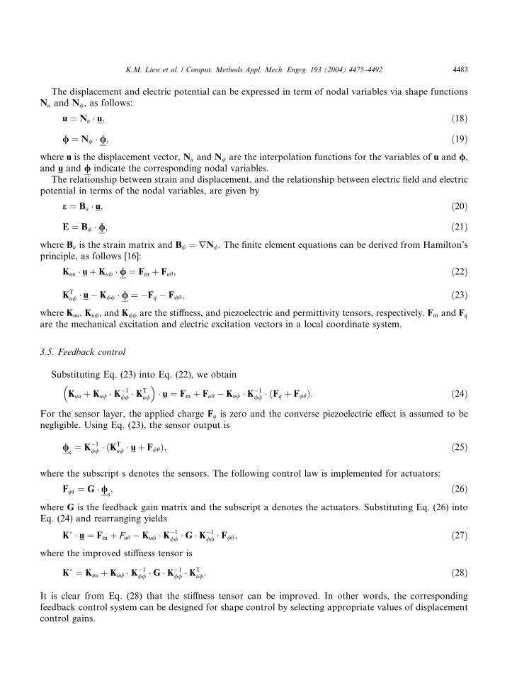
The displacement and electric potential can be expressed in term of nodal variables via shape functionsNu and N/, as follows:
u ¼ Nu � u; ð18Þ
/ ¼ N/ � /; ð19Þ
where u is the displacement vector, Nu and N/ are the interpolation functions for the variables of u and /,and u and / indicate the corresponding nodal variables.
The relationship between strain and displacement, and the relationship between electric field and electric
potential in terms of the nodal variables, are given by
e ¼ Bu � u; ð20Þ
E ¼ B/ � /; ð21Þ
where Bu is the strain matrix and B/ ¼ rN/. The finite element equations can be derived from Hamilton’s
principle, as follows [16]:
Kuu � uþ Ku/ � / ¼ Fm þ Fuh; ð22Þ
KTu/ � u� K// � / ¼ �Fq � F/h; ð23Þ
where Kuu, Ku/, and K// are the stiffness, and piezoelectric and permittivity tensors, respectively. Fm and Fq
are the mechanical excitation and electric excitation vectors in a local coordinate system.
3.5. Feedback control
Substituting Eq. (23) into Eq. (22), we obtain
Kuu
�þ Ku/ � K�1
// � KTu/
�� u ¼ Fm þ Fuh � Ku/ � K�1
// � ðFq þ F/hÞ: ð24Þ
For the sensor layer, the applied charge Fq is zero and the converse piezoelectric effect is assumed to be
negligible. Using Eq. (23), the sensor output is
/s¼ K�1
// � ðKTu/ � uþ F/hÞ; ð25Þ
where the subscript s denotes the sensors. The following control law is implemented for actuators:
Fqa ¼ G � /s; ð26Þ
where G is the feedback gain matrix and the subscript a denotes the actuators. Substituting Eq. (26) intoEq. (24) and rearranging yields
K� � u ¼ Fm þ Fuh � Ku/ � K�1// �G � K�1
// � F/h; ð27Þ
where the improved stiffness tensor is
K� ¼ Kuu þ Ku/ � K�1// �G � K�1
// � KTu/: ð28Þ
It is clear from Eq. (28) that the stiffness tensor can be improved. In other words, the corresponding
feedback control system can be designed for shape control by selecting appropriate values of displacementcontrol gains.

4484 K.M. Liew et al. / Comput. Methods Appl. Mech. Engrg. 193 (2004) 4475–4492
4. Numerical examples
To validate the proposed shape control algorithm with results that are available in the literature, we have
examined the shape control of a clamped–clamped beam, as shown in Fig. 3. The results are compared with
those of Ribeiro et al. [22] as shown in Table 1 and Fig. 4. In this example, the voltage limit is set to be ±500
V. A population size of 20 individuals is allowed to perform a maximum of 20,000 function evaluations. It
is evident that the results of the pre-defined shape fit much better than those obtained by the GA approach.
This demonstrates the accuracy of the current algorithm.In the following, two carefully chosen examples are presented for the shape control of FGM plates. The
first is to arrive at optimum actuator voltages for the open loop shape control, and the second is to arrive at
optimum gain values for the closed loop shape control. The functionally graded material (FGM) is com-
V1 V2 V3 V4 V5 V6
15 in
1.5 in 1 in
1.5
in
8
1 in 8
7 in
Fig. 3. Configuration of the clamped–clamped beam with six pairs of piezoelectric patches.
Table 1
Comparison of the actuator voltage (V) obtained by the current algorithm and the GA approach with voltage limit equal to ±500 V
V1 V2 V3 V4 V5 V6
Current simulation 163.2 )473.5 324.4 352.1 )462.8 121.3
GA simulation 282.8 )496.3 94.6 381.2 )450.2 )72.4
0 2 4 6 8 10 12 14 160.00
0.01
0.02
0.03
0.04
0.05
Pre-defined Achieved (GA Simulation) Achieved (Current Simulation)
Longitudinal Position (in)
Tra
nsve
rsal
Dis
plac
emen
t (i
n)
Fig. 4. Comparison of the current algorithm and the GA approach.

Table 2
Relevant material property specifications
Properties Zirconia Aluminum G-1195N
Elastic modulus E (N/m2) 151· 109 70· 109 63 · 109Poison’s ratio m 0.3 0.3 0.3
Density q (kg/m3) 3000 2707 7600
Thermal conductivity k (W/mK) 2.09 204 5.0
Coefficient of thermal expansion a 10· 10�6 23· 10�6 1.2 · 10�4
Piezoelectric constant d31 (m/V) – – 254· 10�12
Piezoelectric constant d32 (m/V) – – 254· 10�12
Dielectric coefficients k33 (F/m) – – 15 · 10�9
Pyroelectric constant pk (C/m2 K) – – 0.25· 10�4
K.M. Liew et al. / Comput. Methods Appl. Mech. Engrg. 193 (2004) 4475–4492 4485
posed of zirconia (ceramic) and aluminum (metal), and its properties are graded in the thickness directionaccording to a volume fraction power-law distribution. The plates are 400 mm long, 200 mm wide, and
2 mm thick. Both the top and bottom surfaces are bonded with sixteen G-1195N piezoelectric patches. Each
of the patches is 0.1 mm thick. The relevant material properties for G-1195N and the zirconia/aluminum
constituents are given in Table 2.
4.1. Example 1: Optimal actuator voltage design
A cantilevered FGM plate, as shown in Fig. 5, is considered for the shape control. Both the top andbottom piezoelectric patches are used as actuators and equal-amplitude active voltages of opposite sign are
applied to the piezoelectric patches, through the thickness, across the top and the bottom piezoelectric
patches. The third vibration mode of the cantilevered FGM plate with volume fraction n ¼ 1 is selected as
the desired shape of the FGM plate, as shown in Fig. 6. To achieve the desired shape through evaluation
algorithms, the actuator voltages are taken as design variables. For the symmetry of both the FGM plate
and the desired shape, only the eight voltages, V1, V2, V3, V4, V5, V6, V7, and V8, that are applied to the
actuators, as shown in Fig. 5, are needed as variables for the open loop shape control. The voltage limit is
set to ±1000 V, and a population size of 50 individuals is allowed to perform a maximum of 5050 functionevaluations. To search for the actuator voltages for the optimal shape control effectively, 128 elements
(16 · 8) are used to model the cantilevered FGM plate. The achieved shape of the cantilevered FGM plate is
Fig. 5. Configuration of the cantilevered FGM plate with 16 pairs of piezoelectric patches.

0
50
100
150
200 0100
200300
400
–4
–2
0
2
4
y (mm
)
w (
mm
)
x (mm)
Fig. 6. Third mode shape of the cantilevered FGM plate for volume fraction exponent n ¼ 1.
4486 K.M. Liew et al. / Comput. Methods Appl. Mech. Engrg. 193 (2004) 4475–4492
calculated and presented in Fig. 7 for the zirconia’s volume fraction exponent n ¼ 1. The effect of the
zirconia’s constituent volume fraction Vz ¼ ðz=hþ 0:5Þn on the optimal voltages is studied by varying the
value of the power law exponent n. The obtained actuator voltages for the shape control are presented inTable 3 for various volume friction n values. With these actuator voltages, the shape of the cantilevered
FGM plate can be controlled to the desired shape, as shown in Fig. 6, for various values of volume fraction
n. The corresponding centerline deflections and top free edge of the FGM plates are shown in Figs. 8 and 9,
respectively, for comparison with the desired shape. It is clear that the algorithm is able to identify the
optimal voltage distribution for the FGM plate to achieve the desired shape. To indicate the convergence
capability of the algorithm, the convergence history of the algorithm for the optimal actuator voltage
design is plotted in Fig. 10. It can be observed from Fig. 10 that the algorithm converges very fast to its
optimal value within 550 evaluations.
050
100
150
2000
100200
300400
–4
–2
0
2
4
w (
mm
)w
(m
m)
y (mm
)
x (mm)
Fig. 7. Voltage-controlled displacement field for volume fraction exponent n ¼ 1.
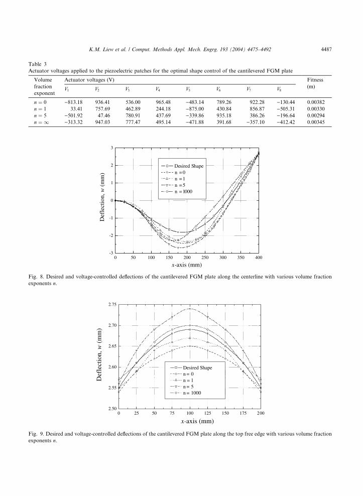
0 25 50 75 100 125 150 175 2002.50
2.55
2.60
2.65
2.70
2.75
Desired Shape n = 0 n = 1 n = 5 n = 1000
x-axis (mm)
Def
lect
ion,
w (
mm
)
Fig. 9. Desired and voltage-controlled deflections of the cantilevered FGM plate along the top free edge with various volume fraction
exponents n.
0 50 100 150 200 250 300 350 400-3
-2
-1
0
1
2
3
Desired Shape n = 0 n = 1 n = 5 n = 1000
x-axis (mm)
Def
lect
ion,
w (
mm
)
Fig. 8. Desired and voltage-controlled deflections of the cantilevered FGM plate along the centerline with various volume fraction
exponents n.
Table 3
Actuator voltages applied to the piezoelectric patches for the optimal shape control of the cantilevered FGM plate
Volume
fraction
exponent
Actuator voltages (V) Fitness
(m)V1 V2 V3 V4 V5 V6 V7 V8
n ¼ 0 )813.18 936.41 536.00 965.48 )483.14 789.26 922.28 )130.44 0.00382
n ¼ 1 33.41 757.69 462.89 244.18 )875.00 430.84 856.87 )505.31 0.00330
n ¼ 5 )501.92 47.46 780.91 437.69 )339.86 935.18 386.26 )196.64 0.00294
n ¼ 1 )313.32 947.03 777.47 495.14 )471.88 391.68 )357.10 )412.42 0.00345
K.M. Liew et al. / Comput. Methods Appl. Mech. Engrg. 193 (2004) 4475–4492 4487

0 1000 2000 3000 4000 5000 60000.000
0.001
0.002
0.003
0.004
0.005
0.006
0.007
Evaluation of objective function
Fitn
ess
valu
es
Fig. 10. Convergence history of the optimal actuator voltage design.
4488 K.M. Liew et al. / Comput. Methods Appl. Mech. Engrg. 193 (2004) 4475–4492
4.2. Example 2: Optimal gain design
In this section, the cantilevered FGM plate shown in Fig. 5 is again considered for its shape control by
optimizing the values of the gain matrix. The top piezoelectric patches are used as actuators and the bottom
piezoelectric patches are used as sensors for the closed loop feedback control. The top zirconia rich surfaceof the FGM plate is exposed to a temperature of 0 �C, and the bottom aluminum rich surface is exposed to
a temperature of 1 �C. The temperature field through the thickness of the FGM plate is calculated for
various values of volume fraction n and shown in Fig. 11. Due to the temperature gradient, an initial
-1.0
-0.5
0.0
0.5
1.0
0 2 4 6 8 1 0
Aluminum Zirconia n = 15 n = 5 n = 2 n = 1 n = 0.5 n = 0.2
Temperature in (oC)
Non
-dim
ensi
onal
thic
knes
s, z
/h
Fig. 11. Temperature field through the thickness of the FGM plate.

0
100
200
0100
200300
400
-2
-1
0
1
2
3
x (mm)
y (mm)
w (m
m)
Fig. 12. Seventh mode shape of the cantilevered FGM plate for volume fraction exponent n ¼ 1.
Table 4
Displacement gain parameters applied to the piezoelectric patches for the optimal shape control of the cantilevered FGM plate
Volume
fraction
exponent
Displacement gain parameters Fitness
(m)G1 G2 G3 G4 G5 G6 G7 G8
n ¼ 0 )0.006346 )0.009061 0.009022 0.009969 )0.003761 0.002250 0.009906 )0.003744 0.005214
n ¼ 1 )0.003508 0.009056 )0.001489 0.007069 0.009451 0.009896 0.009340 0.009203 0.004991
n ¼ 5 0.007891 0.008325 )0.006441 0.007131 )0.007297 0.008963 0.009846 0.007433 0.004143
n ¼ 1 0.005914 0.009134 )0.008405 0.008038 )0.005315 0.004414 0.009905 )0.005301 0.004110
0
50
100
150
200
0100
200300
400
-2
-1
0
1
2
3
x (mm)
y (mm)
w (
mm
)
Fig. 13. Displacement gain-controlled displacement field for volume fraction exponent.
K.M. Liew et al. / Comput. Methods Appl. Mech. Engrg. 193 (2004) 4475–4492 4489

4490 K.M. Liew et al. / Comput. Methods Appl. Mech. Engrg. 193 (2004) 4475–4492
deflection will be induced. Thus, the strains of the bottom surface will be sensed by the bottom sensorpatches, and then the sensed voltages will be fed back to the collocated top actuator patches to control the
FGM plate into a desired shape through the selection of appropriate gain values. The seventh vibration
mode of the cantilevered FGM plate with volume fraction exponent n ¼ 1 is selected as the desired shape of
the FGM plate, as shown in Fig. 12. To arrive at the desired shape, the gain values are taken as design
variables for the optimization problem. Due to the symmetry of both the FGM plates and the desired
0 50 100 150 200 250 300 350 400-1.6
-1.4
-1.2
-1.0
-0.8
-0.6
-0.4
-0.2
0.0
Desired Shape n = 0 n = 1 n = 5 n = 1000
x-axis (mm)
Def
lect
ion,
w (
mm
)
Fig. 14. Desired and gain-controlled deflections of the cantilevered FGM plate along centerline with various volume fraction expo-
nents n.
0 25 50 75 100 125 150 175 200-3
-2
-1
0
1
2
3
Desired Shape n = 0 n = 1 n = 5 n = 1000
Def
lect
ion,
w (
mm
)
x-axis (mm)
Fig. 15. Desired and gain-controlled deflections of the cantilevered FGM plate along the top free edge with various volume fraction
exponents n.

0 1000 2000 3000 4000 5000 60000.0062
0.0064
0.0066
0.0068
0.0070
0.0072
0.0074
0.0076
Evaluation of objective function
Fitn
ess
valu
es
Fig. 16. Convergence history of the optimal gain matrix design.
K.M. Liew et al. / Comput. Methods Appl. Mech. Engrg. 193 (2004) 4475–4492 4491
shape, only eight gain values (G1 to G8) are applied to the collocated sensors/actuators (Fig. 5) for the
closed loop feedback control. The gain limit is set to ±0.01. A population of 50 individuals is allowed to
perform a maximum of 5050 function evaluations. 128 elements (16 · 8) are used to mesh the cantilevered
FGM plate. The optimal gain values for volume fraction exponent n ¼ 0, n ¼ 1, n ¼ 5, and n ¼ 1 are
obtained using CI. Table 4 presents the obtained gain values for the optimal shape control for variousconstituent volume fractions of zirconia as well as different levels of fitness. The achieved shape of the
cantilevered FGM plate is shown in Fig. 13 for the zirconia’s volume fraction exponent n ¼ 1. For com-
parison with the desired shape, the respective achieved deflections of the cantilevered FGM plate along the
top free edge and the centerline of the FGM plate are plotted in Figs. 14 and 15 for various zirconia volume
fraction exponents n. It can be seen again from the results that with the appropriate population size and
number of time steps, the gain values can be optimized to control the shape of FGM plate into a desired
shape by using CI. Fig. 16 shows the convergence history of the algorithm for the optimal gain matrix
design. From these two examples, we found that the proposed algorithm is efficient and its convergence isfast.
5. Conclusions
In an extension of earlier work that was conducted by the authors [12–17], a new optimization algorithm
based on computational intelligence (CI) is used along with a modified finite element formulation to deal
with the shape control of FGM plates that contain piezoelectric sensor and actuator patches. To control theFGM plates into a desired shape, the algorithm based on CI has been used to derive the optimal voltage
distribution or gain control matrix. To the best of the our knowledge, the displacement gain matrix is used
as a design variable for the shape control of smart structures for the first time. Numerical simulations have
been successfully carried out on the shape control of the FGM plates by optimizing the voltage distribution
for the open loop shape control or gain values for the closed loop shape control. The effect of the volume
fraction of zirconia on the optimal voltages and gain values has also been examined. The results demon-
strate the ability of the algorithm based on CI as an effective tool for the optimal shape control of FGM
plates.

4492 K.M. Liew et al. / Comput. Methods Appl. Mech. Engrg. 193 (2004) 4475–4492
References
[1] M. Yamanouchi, T. Hirai, I. Shiota, in: Proceedings of the First International Symposium on Functionally Gradient Materials,
Japan, 1990.
[2] G.N. Praveen, J.N. Reddy, Nonlinear transient thermoelastic analysis of functionally graded ceramic–metal plates, Int. J. Solids
Struct. 35 (1998) 4457–4476.
[3] K.M. Liew, S. Kitipornchai, X.Z. Zhang, C.W. Lim, Analysis of the thermal stress behaviour of functionally graded hollow
circular cylinder, Int. J. Solids Struct. 40 (2003) 2355–2380.
[4] T.Y. Ng, K.Y. Lam, K.M. Liew, Effects of FGM materials on the parametric resonance of plate structures, Comput. Methods
Appl. Mech. Engrg. 190 (2000) 953–962.
[5] J.F. Rivory, C.H. Hansen, J. Pan, Further studies of the dynamic response of a simply-supported beam excited by a pair of out of
phase piezoelectric actuators, J. Intell. Mater. Syst. Struct. 5 (1994) 654–664.
[6] C.Q. Chen, Y.P. Shen, X.M. Wang, Exact solution of orthotropic cylindrical shell with piezoelectric layers under cylindrical
bending, Int. J. Solids Struct. 33 (1996) 4457–4476.
[7] J.N. Reddy, On laminated composite plates with integrated sensors and actuators, Engrg. Struct. 21 (1999) 568–593.
[8] K.M. Liew, H.K. Lim, M.J. Tan, X.Q. He, Analysis of laminated composite beams and plates with piezoelectric patches using the
element-free Galerkin method, Comput. Mech. 29 (2002) 486–497.
[9] H. Allik, T.J.R. Hughes, Finite element method for piezoelectric vibration, Int. J. Numer. Methods Engrg. 2 (1970) 151–157.
[10] R. Lammering, Application of finite shell element for composite containing piezoelectric polymers in vibration control, Comput.
Struct. 41 (1991) 1101–1109.
[11] W.S. Hwang, H.C. Park, W.B. Hwang, Vibration control of laminated plates with piezoelectric sensors and actuators: finite
element formulation and model analysis, J. Intell. Mater. Syst. Struct. 4 (1993) 317–329.
[12] K.M. Liew, X.Q. He, T.Y. Ng, S. Kitipornchai, Finite element piezothermoelasticity analysis and the active control of FGM
plates with integrated piezoelectric sensors and actuators, Comput. Mech. 31 (2003) 350–358.
[13] K.M. Liew, X.Q. He, T.Y. Ng, S. Sivashanker, Active control of FGM plates subjected to a temperature gradient: modelling via
finite element method based on FSDT, Int. J. Numer. Methods Engrg. 52 (2001) 1253–1271.
[14] K.M. Liew, X.Q. He, T.Y. Ng, S. Kitipornchai, Active control of FGM shells subjected to a temperature gradient via piezoelectric
sensor/actuator patches, Int. J. Numer. Methods Engrg. 55 (2002) 653–668.
[15] K.M. Liew, S. Sivashanker, X.Q. He, T.Y. Ng, Modelling and design of smart structures using functionally graded materials and
piezoelectric sensor/actuator patches, Smart Mater. Struct. 12 (2003) 647–655.
[16] X.Q. He, T.Y. Ng, S. Sivashanker, K.M. Liew, Active control of FGM plates with integrated piezoelectric sensors and actuators,
Int. J. Solids Struct. 38 (2001) 1641–1655.
[17] X.Q. He, K.M. Liew, T.Y. Ng, S. Sivashanker, A FEM model for the active control of curved FGM shells using piezoelectric
sensor/actuator layers, Int. J. Numer. Methods Engrg. 54 (2002) 853–870.
[18] D.B. Koconis, L.P. Kollar, G.S. Springer, Shape control of composite plates and shells with embedded actuators––I: voltages
specified, J. Compos. Mater. 28 (1994) 415–458.
[19] K. Chandrashekhara, S. Varadarajan, Adaptive shape control of composite beams with piezoelectric actuators, J. Intell. Mater.
Syst. Struct. 8 (1997) 112–124.
[20] C.M. Wang, K.K. Ang, A. Ajit, Shape control of laminated cantilevered beams with piezoelectric actuators, J. Intell. Mater. Syst.
Struct. 10 (1999) 164–175.
[21] D. Tong, S.K. Agrawal, R.L. Williams, Optimal shape control of composite thin plates with piezoelectric actuators, J. Intell.
Mater. Syst. Struct. 9 (1998) 458–467.
[22] R. Ribeiro, S.D.M. Silva, J.D. Rodrigues, M. Vaz, Genetic algorithms for optimal design and control of adaptive structures, Proc.
SPIE––Int. Soc. Opt. Engrg. 3984 (2000) 268–278.
[23] T.Y. Ng, X.Q. He, K.M. Liew, Finite element modeling of active control of functionally graded shells in frequency domain via
piezoelectric sensors and actuators, Comput. Mech. 28 (2002) 1–9.
[24] Y. Shi, R.C. Eberhart, Empirical study of particle swarm optimization, in: Proceedings of the 1999 Congress on Evolutionary
Computation, IEEE Service Center, Piscataway, NJ, 1999, pp. 1945–1950.
[25] T. Ray, K. Tai, K.C. Seow, An evolutionary algorithm for constrained optimization, in: Proceedings of the Genetic and
Evolutionary Computation Conference, Morgan Kaufmann Publishers, 2000, pp. 771–777.
[26] N. Srinivas, K. Deb, Multiobjective optimization using nondominated sorting in genetic algorithms, Evol. Comput. 2 (1994) 221–
248.
[27] T. Ray, K. Tai, K.C. Seow, Multiobjective design optimization by an evolutionary algorithm, Engrg. Optim. 33 (2001) 399–424.
[28] T. Ray, K.M. Liew, A swarm metaphor for multiobjective design optimization, Engrg. Optim. 34 (2002) 141–153.
[29] T. Ray, K.M. Liew, P. Saini, An intelligent information sharing strategy within a swarm for unconstrained and constrained
optimization problems, Soft Comput. 6 (2002) 38–44.


![Thermo-elastic bending analysis of functionally graded sandwich … · 2018-12-11 · analysis of functionally graded plates [28]. Tounsi et al. developed a re ned trigonometric shear](https://img.pdfslide.net/doc/110x75/5ed8ed5c6714ca7f4768d490/thermo-elastic-bending-analysis-of-functionally-graded-sandwich-2018-12-11-analysis.jpg)