Embed Size (px)
Citation preview
Workshop on Material Appearance Modeling (2019)H. Rushmeier and R. Klein (Editors)
On Visual Attractiveness of Anisotropic Effect Coatings
J. Filip, M. Kolafová
The Czech Academy of Sciences, Institute of Information Theory and Automation, Prague, Czech Republic
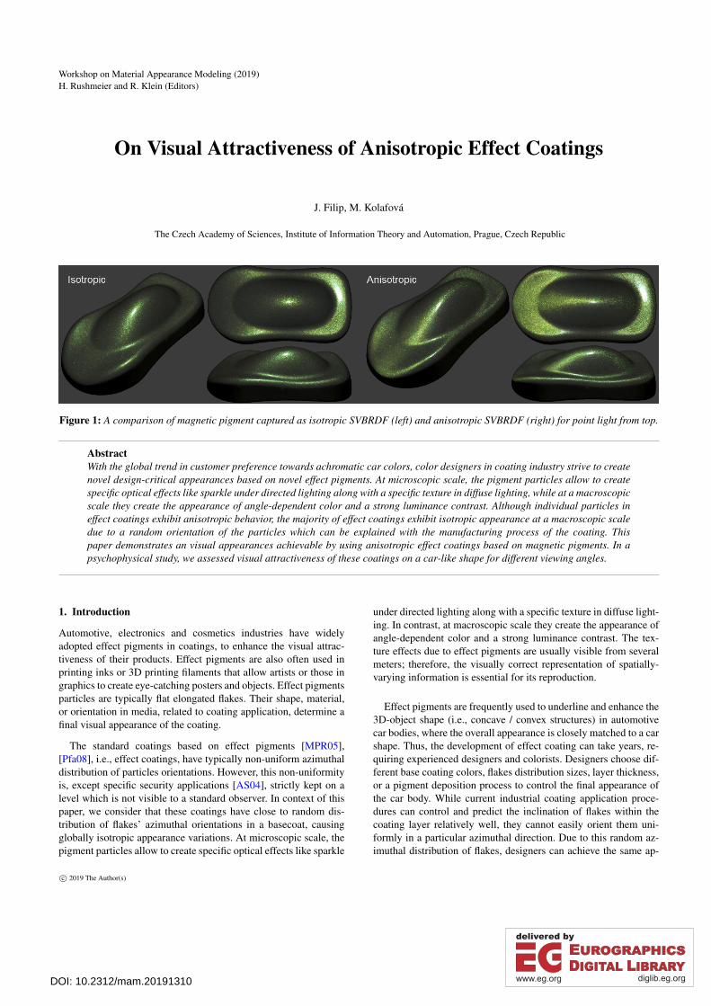
Figure 1: A comparison of magnetic pigment captured as isotropic SVBRDF (left) and anisotropic SVBRDF (right) for point light from top.
AbstractWith the global trend in customer preference towards achromatic car colors, color designers in coating industry strive to createnovel design-critical appearances based on novel effect pigments. At microscopic scale, the pigment particles allow to createspecific optical effects like sparkle under directed lighting along with a specific texture in diffuse lighting, while at a macroscopicscale they create the appearance of angle-dependent color and a strong luminance contrast. Although individual particles ineffect coatings exhibit anisotropic behavior, the majority of effect coatings exhibit isotropic appearance at a macroscopic scaledue to a random orientation of the particles which can be explained with the manufacturing process of the coating. Thispaper demonstrates an visual appearances achievable by using anisotropic effect coatings based on magnetic pigments. In apsychophysical study, we assessed visual attractiveness of these coatings on a car-like shape for different viewing angles.
1. Introduction
Automotive, electronics and cosmetics industries have widelyadopted effect pigments in coatings, to enhance the visual attrac-tiveness of their products. Effect pigments are also often used inprinting inks or 3D printing filaments that allow artists or those ingraphics to create eye-catching posters and objects. Effect pigmentsparticles are typically flat elongated flakes. Their shape, material,or orientation in media, related to coating application, determine afinal visual appearance of the coating.
The standard coatings based on effect pigments [MPR05],[Pfa08], i.e., effect coatings, have typically non-uniform azimuthaldistribution of particles orientations. However, this non-uniformityis, except specific security applications [AS04], strictly kept on alevel which is not visible to a standard observer. In context of thispaper, we consider that these coatings have close to random dis-tribution of flakes’ azimuthal orientations in a basecoat, causingglobally isotropic appearance variations. At microscopic scale, thepigment particles allow to create specific optical effects like sparkle
under directed lighting along with a specific texture in diffuse light-ing. In contrast, at macroscopic scale they create the appearance ofangle-dependent color and a strong luminance contrast. The tex-ture effects due to effect pigments are usually visible from severalmeters; therefore, the visually correct representation of spatially-varying information is essential for its reproduction.
Effect pigments are frequently used to underline and enhance the3D-object shape (i.e., concave / convex structures) in automotivecar bodies, where the overall appearance is closely matched to a carshape. Thus, the development of effect coating can take years, re-quiring experienced designers and colorists. Designers choose dif-ferent base coating colors, flakes distribution sizes, layer thickness,or a pigment deposition process to control the final appearance ofthe car body. While current industrial coating application proce-dures can control and predict the inclination of flakes within thecoating layer relatively well, they cannot easily orient them uni-formly in a particular azimuthal direction. Due to this random az-imuthal distribution of flakes, designers can achieve the same ap-
c© 2019 The Author(s)
DOI: 10.2312/mam.20191310 https://diglib.eg.orghttps://www.eg.org
32 J. Filip, M. Kolafová / On Visual Attractiveness of Anisotropic Effect Coatings
pearance at a macroscopic level regardless of the rotation of thematerial. We call this constant azimuthal behavior, isotropic.
In this paper, we build on our recent work on analysis of attrac-tivenes of anisotropic reflections on a car body shape [FK18]. Butinstead of anisotropy simulation using a BRDF model, we capturedSVBRDF of two coatings containing magnetic pigment allowing tocontrol anisotropy direction. We visualized the captured data on acar body shape and analyzed its visual attractiveness as a functionof anisotropic axis alignment (see Fig. 1). To address this task weran a psychophysical experiment obtaining human judgments fordifferent observation directions.
2. Related Work
Effect pigments can be, based on the principle of chroma andsparkling effect generation, roughly divided into three categories[MPR05], [Pfa08]: metallic , interference, and diffractive pigments.Metallic pigments rely mainly on geometrical properties of flakesand their reflectance, interference pigments introduce effects due tolight wave interference with transparent substrate coated with mate-rials of high refractive indices, and diffraction pigments decomposelight at a diffraction grating of a frequency close to the wavelengthof the incoming light. Note that in practice many effect coatingsare often combinations of the above classes. Lans et al. [LKH12]presented an empirical approach to the realistic modelling of spe-cial effect flakes fitting patch-based model parameters using sparsetexture data obtained by a portable multi-angle spectrophotometer.In [RSK09] were presented extensions towards gonioapparent coat-ings texture measurement and modelling using bidirectional texturefunction (BTF) [DvGNK99]. Pereira et al. [PLMR17] suggestedfabrication of printing custom based anisotropic BRDFs by using atime-varying magnetic field and photo-cured resin. In [Fil15] wasshown that material anisotropy produces a more visually attractiveappearance.
Our recent work [FK18] has shown that car body observers sys-tematically prefer a certain orientation of anisotropy axis regard-less of the surrounding illumination. This work deal with specificanisotropy type, i.e., effect coating containing magnetic pigmentsthat create strong azimuthally dependent effects. We are not awareof any work psychophysically analyzing captured and visualizedspatially-varying appearance of anisotropic effect coatings.
3. Tested effect coatings
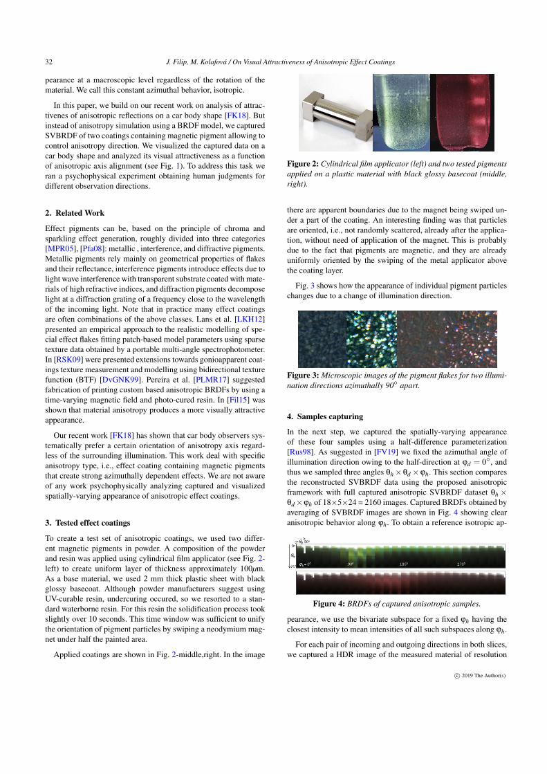
To create a test set of anisotropic coatings, we used two differ-ent magnetic pigments in powder. A composition of the powderand resin was applied using cylindrical film applicator (see Fig. 2-left) to create uniform layer of thickness approximately 100µm.As a base material, we used 2 mm thick plastic sheet with blackglossy basecoat. Although powder manufacturers suggest usingUV-curable resin, undercuring occured, so we resorted to a stan-dard waterborne resin. For this resin the solidification process tookslightly over 10 seconds. This time window was sufficient to unifythe orientation of pigment particles by swiping a neodymium mag-net under half the painted area.
Applied coatings are shown in Fig. 2-middle,right. In the image
Figure 2: Cylindrical film applicator (left) and two tested pigmentsapplied on a plastic material with black glossy basecoat (middle,right).
there are apparent boundaries due to the magnet being swiped un-der a part of the coating. An interesting finding was that particlesare oriented, i.e., not randomly scattered, already after the applica-tion, without need of application of the magnet. This is probablydue to the fact that pigments are magnetic, and they are alreadyuniformly oriented by the swiping of the metal applicator abovethe coating layer.
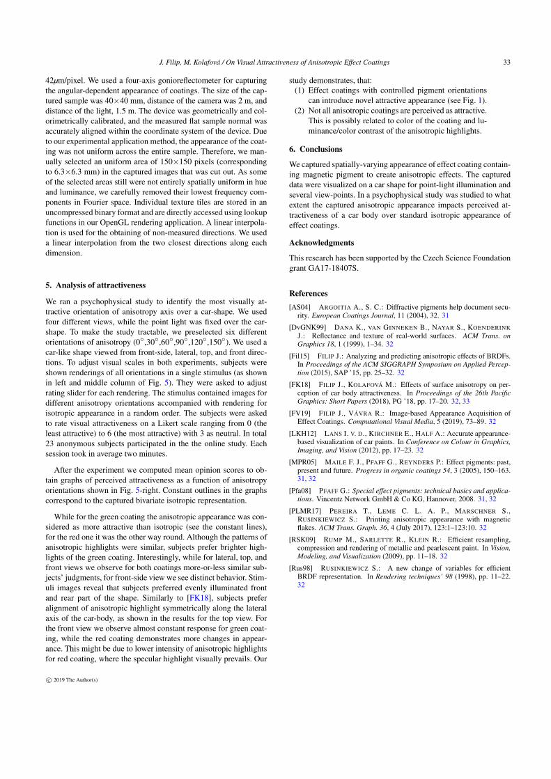
Fig. 3 shows how the appearance of individual pigment particleschanges due to a change of illumination direction.
Figure 3: Microscopic images of the pigment flakes for two illumi-nation directions azimuthally 90◦ apart.
4. Samples capturing
In the next step, we captured the spatially-varying appearanceof these four samples using a half-difference parameterization[Rus98]. As suggested in [FV19] we fixed the azimuthal angle ofillumination direction owing to the half-direction at ϕd = 0◦, andthus we sampled three angles θh ×θd ×ϕh. This section comparesthe reconstructed SVBRDF data using the proposed anisotropicframework with full captured anisotropic SVBRDF dataset θh ×θd ×ϕh of 18×5×24 = 2160 images. Captured BRDFs obtained byaveraging of SVBRDF images are shown in Fig. 4 showing clearanisotropic behavior along ϕh. To obtain a reference isotropic ap-
Figure 4: BRDFs of captured anisotropic samples.
pearance, we use the bivariate subspace for a fixed ϕh having theclosest intensity to mean intensities of all such subspaces along ϕh.
For each pair of incoming and outgoing directions in both slices,we captured a HDR image of the measured material of resolution
c© 2019 The Author(s)
J. Filip, M. Kolafová / On Visual Attractiveness of Anisotropic Effect Coatings 33
42µm/pixel. We used a four-axis gonioreflectometer for capturingthe angular-dependent appearance of coatings. The size of the cap-tured sample was 40×40 mm, distance of the camera was 2 m, anddistance of the light, 1.5 m. The device was geometrically and col-orimetrically calibrated, and the measured flat sample normal wasaccurately aligned within the coordinate system of the device. Dueto our experimental application method, the appearance of the coat-ing was not uniform across the entire sample. Therefore, we man-ually selected an uniform area of 150×150 pixels (correspondingto 6.3×6.3 mm) in the captured images that was cut out. As someof the selected areas still were not entirely spatially uniform in hueand luminance, we carefully removed their lowest frequency com-ponents in Fourier space. Individual texture tiles are stored in anuncompressed binary format and are directly accessed using lookupfunctions in our OpenGL rendering application. A linear interpola-tion is used for the obtaining of non-measured directions. We useda linear interpolation from the two closest directions along eachdimension.
5. Analysis of attractiveness
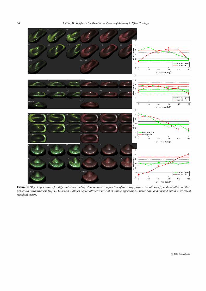
We ran a psychophysical study to identify the most visually at-tractive orientation of anisotropy axis over a car-shape. We usedfour different views, while the point light was fixed over the car-shape. To make the study tractable, we preselected six differentorientations of anisotropy (0◦,30◦,60◦,90◦,120◦,150◦). We used acar-like shape viewed from front-side, lateral, top, and front direc-tions. To adjust visual scales in both experiments, subjects wereshown renderings of all orientations in a single stimulus (as shownin left and middle column of Fig. 5). They were asked to adjustrating slider for each rendering. The stimulus contained images fordifferent anisotropy orientations accompanied with rendering forisotropic appearance in a random order. The subjects were askedto rate visual attractiveness on a Likert scale ranging from 0 (theleast attractive) to 6 (the most attractive) with 3 as neutral. In total23 anonymous subjects participated in the the online study. Eachsession took in average two minutes.
After the experiment we computed mean opinion scores to ob-tain graphs of perceived attractiveness as a function of anisotropyorientations shown in Fig. 5-right. Constant outlines in the graphscorrespond to the captured bivariate isotropic representation.
While for the green coating the anisotropic appearance was con-sidered as more attractive than isotropic (see the constant lines),for the red one it was the other way round. Although the patterns ofanisotropic highlights were similar, subjects prefer brighter high-lights of the green coating. Interestingly, while for lateral, top, andfront views we observe for both coatings more-or-less similar sub-jects’ judgments, for front-side view we see distinct behavior. Stim-uli images reveal that subjects preferred evenly illuminated frontand rear part of the shape. Similarly to [FK18], subjects preferalignment of anisotropic highlight symmetrically along the lateralaxis of the car-body, as shown in the results for the top view. Forthe front view we observe almost constant response for green coat-ing, while the red coating demonstrates more changes in appear-ance. This might be due to lower intensity of anisotropic highlightsfor red coating, where the specular highlight visually prevails. Our
study demonstrates, that:(1) Effect coatings with controlled pigment orientations
can introduce novel attractive appearance (see Fig. 1).(2) Not all anisotropic coatings are perceived as attractive.
This is possibly related to color of the coating and lu-minance/color contrast of the anisotropic highlights.
6. Conclusions
We captured spatially-varying appearance of effect coating contain-ing magnetic pigment to create anisotropic effects. The captureddata were visualized on a car shape for point-light illumination andseveral view-points. In a psychophysical study was studied to whatextent the captured anisotropic appearance impacts perceived at-tractiveness of a car body over standard isotropic appearance ofeffect coatings.
Acknowledgments
This research has been supported by the Czech Science Foundationgrant GA17-18407S.
References[AS04] ARGOITIA A., S. C.: Diffractive pigments help document secu-
rity. European Coatings Journal, 11 (2004), 32. 31
[DvGNK99] DANA K., VAN GINNEKEN B., NAYAR S., KOENDERINKJ.: Reflectance and texture of real-world surfaces. ACM Trans. onGraphics 18, 1 (1999), 1–34. 32
[Fil15] FILIP J.: Analyzing and predicting anisotropic effects of BRDFs.In Proceedings of the ACM SIGGRAPH Symposium on Applied Percep-tion (2015), SAP ’15, pp. 25–32. 32
[FK18] FILIP J., KOLAFOVÁ M.: Effects of surface anisotropy on per-ception of car body attractiveness. In Proceedings of the 26th PacificGraphics: Short Papers (2018), PG ’18, pp. 17–20. 32, 33
[FV19] FILIP J., VÁVRA R.: Image-based Appearance Acquisition ofEffect Coatings. Computational Visual Media, 5 (2019), 73–89. 32
[LKH12] LANS I. V. D., KIRCHNER E., HALF A.: Accurate appearance-based visualization of car paints. In Conference on Colour in Graphics,Imaging, and Vision (2012), pp. 17–23. 32
[MPR05] MAILE F. J., PFAFF G., REYNDERS P.: Effect pigments: past,present and future. Progress in organic coatings 54, 3 (2005), 150–163.31, 32
[Pfa08] PFAFF G.: Special effect pigments: technical basics and applica-tions. Vincentz Network GmbH & Co KG, Hannover, 2008. 31, 32
[PLMR17] PEREIRA T., LEME C. L. A. P., MARSCHNER S.,RUSINKIEWICZ S.: Printing anisotropic appearance with magneticflakes. ACM Trans. Graph. 36, 4 (July 2017), 123:1–123:10. 32
[RSK09] RUMP M., SARLETTE R., KLEIN R.: Efficient resampling,compression and rendering of metallic and pearlescent paint. In Vision,Modeling, and Visualization (2009), pp. 11–18. 32
[Rus98] RUSINKIEWICZ S.: A new change of variables for efficientBRDF representation. In Rendering techniques’ 98 (1998), pp. 11–22.32
c© 2019 The Author(s)
34 J. Filip, M. Kolafová / On Visual Attractiveness of Anisotropic Effect Coatings
Figure 5: Object appearance for different views and top illumination as a function of anisotropy axis orientation (left) and (middle) and theirperceived attractiveness (right). Constant outlines depict attractiveness of isotropic appearance. Error-bars and dashed outlines representstandard errors.
c© 2019 The Author(s)