Embed Size (px)
Citation preview
OneConnectOCe14000B-series Adapters
Installation Manual
pub-005129 Rev. A Connect • Monitor • Manage

2
Copyright © 2013–2015 Emulex. All rights reserved worldwide. No part of this document may be reproduced by any means or translated to any electronic medium without the prior written consent of Emulex.
Information furnished by Emulex is believed to be accurate and reliable. However, no responsibility is assumed by Emulex for its use; or for any infringements of patents or other rights of third parties which may result from its use. No license is granted by implication or otherwise under any patent, copyright or related rights of Emulex.
Emulex, the Emulex logo, Emulex BladeEngine, Emulex InSpeed, Emulex LightPulse, Emulex OneCommand, Emulex OneConnect, and SLI are registered trademarks, and Emulex Advanced-8, Emulex Connect, Emulex CrossLink, Emulex Engine, Emulex Edge, Emulex ExpressLane, Emulex GreenState, Network Xceleration, Emulex OneCore, Emulex Pilot, Emulex SURF, Emulex Universal Multi-Channel, Emulex vEngine, Emulex Virtual Fabric, Emulex Virtual Network Exceleration, Emulex vPath, Emulex vScale, AutoPilot, AutoPilot Installer, and BlockGuard are trademarks, of Emulex. All other brands or product names referenced herein are trademarks or registered trademarks of their respective companies or organizations.
Emulex provides this manual "as is" without any warranty of any kind, either expressed or implied, including but not limited to the implied warranties of merchantability or fitness for a particular purpose. Emulex may make improvements and changes to the product described in this manual at any time and without any notice. Emulex assumes no responsibility for its use, nor for any infringements of patents or other rights of third parties that may result. Periodic changes are made to information contained herein; although these changes will be incorporated into new editions of this manual, Emulex disclaims any undertaking to give notice of such changes.
Emulex, 3333 Susan Street
Costa Mesa, CA 92626
OneConnect OCe14000B-series Adapters Installation Manual pub-005129 Rev. A
Table of Contents 3
Table of Contents
List of Figures ......................................................................................5
List of Tables .......................................................................................6
1. Introduction .....................................................................................7
Features............................................................................................... 10
General Features.................................................................................10OCe14101B Adapters ................................................................................ 11
OCe14102B Adapters ................................................................................ 11
OCe14104B Adapters ................................................................................ 11
OCe14401B Adapters ................................................................................ 11
Protocol-Specific Capabilities...................................................................... 12
Adapter Identification.............................................................................. 13
Abbreviations ........................................................................................ 13
2. Installation..................................................................................... 16
Preparing the Adapter for Installation .......................................................... 16
Changing the Bracket ...........................................................................16
Enabling or Disabling the Secure Firmware Feature........................................18
Installing the Adapter .............................................................................. 20
3. Attaching Devices to the Adapter......................................................... 21
Connecting Devices to Adapters Using a DAC or AOC Cable ................................ 21
Emulex OneConnect Accessories ..............................................................23
Connecting Devices to Adapters Using an Optical Cable with LC Connectors........... 24
Connecting Devices to Adapters Using a UTP or CAT Cable ................................ 26
4. Applying Power and Viewing the LEDS................................................... 27
Applying Power ...................................................................................... 27
LED Indicators........................................................................................ 27
OCe14102B-NT/UT Adapters ...................................................................27
All Other OCe14000B-series Adapters ........................................................27
Viewing the LEDs .................................................................................... 28
5. References .................................................................................... 30
Specifications ........................................................................................ 30
FCC and Regulatory Notices....................................................................... 31
Declaration of Conformity......................................................................... 33
OneConnect OCe14000B-series Adapters Installation Manual pub-005129 Rev. A
Table of Contents 4
Laser Safety Notice ................................................................................. 34
OneConnect OCe14000B-series Adapters Installation Manual pub-005129 Rev. A

List of Figures 5
OneConnect OCe14000B-series Adapters Installation Manual pub-005129 Rev. A
List of FiguresFigure 1-1 Emulex OCe14102B Adapter................................................... 9Figure 1-2 Emulex OCe14102B-NT/UT Adapter.......................................... 9Figure 1-3 Emulex OCe14401B Adapter..................................................10Figure 2-1 Optical Transceiver Example.................................................16Figure 2-2 Releasing the Latch on an Optical Transceiver............................17Figure 2-3 Removing the Bracket .........................................................17Figure 2-4 Secure Firmware Jumper Location J3 on
OCe14101B14401B-series Adapter...........................................18Figure 2-5 Secure Firmware Jumper Location J6 on OCe14104B-series
Adapter ..........................................................................19Figure 2-6 Secure Firmware Jumper Location J7 on OCe14101B and
OCe14102B-series Adapters ..................................................19Figure 2-7 Secure Jumper Location J24 on OCe14102B-NT and -UT-series
Adapters .........................................................................20Figure 3-1 Connecting a DAC Cable to the OCe14100B-series -NX/-UX
Adapters .........................................................................22Figure 3-2 Connecting a DAC Cable to the OCe14100B-series -NX/-UX
Adapters .........................................................................22Figure 3-3 Installing an Optical Transceiver for the OCe14000B-series
-NM/-UM Adapters .............................................................25Figure 3-4 Connecting a Fiber Optic Cable for the OCe14000B-series
-NM/-UM Adapters .............................................................25Figure 4-1 OCe14101B-NM/-NX, OCe14102B-NM/-NX, and OCe14102B-UX/-UM
Adapter LED Indicators........................................................28Figure 4-2 OCe14401B-NX/-UX Adapter LED Indicators ...............................28Figure 4-3 OCe14102B-NT and OCe14102B-UT LED Indicators .......................29Figure 4-4 OCe14104B-NM/-UM LED Indicators .........................................29

List of Tables 6
OneConnect OCe14000B-series Adapters Installation Manual pub-005129 Rev. A
List of TablesTable 1-1 OCe14000B-series Adapters ................................................... 7
Table 3-1 OCe14101B-NX, OCe14102B-NX/-UX, and OCe14104B-NX/-UX Cable and Connector Specifications ........................................21
Table 3-2 OCe14401B-NX/-UX Cable and Connector Specifications ................21
Table 3-3 OCe14101B-NX, OCe14102B-NX, and OCe14104B-NX/-UX Adapter Emulex OneConnect Accessories ............................................23
Table 3-4 OCe14401B-NX/UX Adapter Emulex OneConnect Accessories...........23
Table 3-5 OCe14101B-NM, OCe14102B-NM/-UM, and OCe14104B-NM/-UM Adapter Cable and Connector Specifications ..............................24
Table 3-6 OCe14102B-NT/-UT Adapter Cable and Connector Specifications .....26
Table 5-1 Adapter Specifications ........................................................30
1. Introduction 7
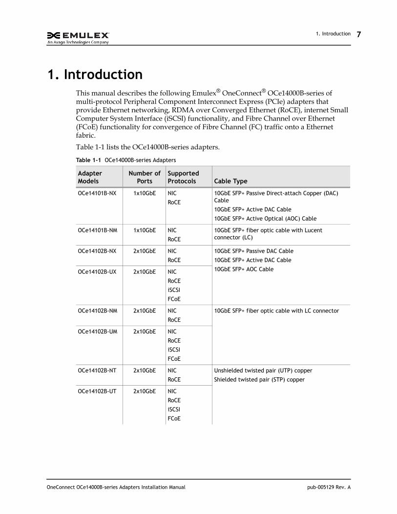
1. IntroductionThis manual describes the following Emulex® OneConnect® OCe14000B-series of multi-protocol Peripheral Component Interconnect Express (PCIe) adapters that provide Ethernet networking, RDMA over Converged Ethernet (RoCE), internet Small Computer System Interface (iSCSI) functionality, and Fibre Channel over Ethernet (FCoE) functionality for convergence of Fibre Channel (FC) traffic onto a Ethernet fabric.
Table 1-1 lists the OCe14000B-series adapters.
Table 1-1 OCe14000B-series Adapters
Adapter Models
Number of Ports
Supported Protocols Cable Type
OCe14101B-NX 1x10GbE NIC
RoCE
10GbE SFP+ Passive Direct-attach Copper (DAC) Cable
10GbE SFP+ Active DAC Cable
10GbE SFP+ Active Optical (AOC) Cable
OCe14101B-NM 1x10GbE NIC
RoCE
10GbE SFP+ fiber optic cable with Lucent connector (LC)
OCe14102B-NX 2x10GbE NIC
RoCE
10GbE SFP+ Passive DAC Cable
10GbE SFP+ Active DAC Cable
10GbE SFP+ AOC CableOCe14102B-UX 2x10GbE NIC
RoCE
iSCSI
FCoE
OCe14102B-NM 2x10GbE NIC
RoCE
10GbE SFP+ fiber optic cable with LC connector
OCe14102B-UM 2x10GbE NIC
RoCE
iSCSI
FCoE
OCe14102B-NT 2x10GbE NIC
RoCE
Unshielded twisted pair (UTP) copper
Shielded twisted pair (STP) copper
OCe14102B-UT 2x10GbE NIC
RoCE
iSCSI
FCoE
OneConnect OCe14000B-series Adapters Installation Manual pub-005129 Rev. A
1. Introduction 8
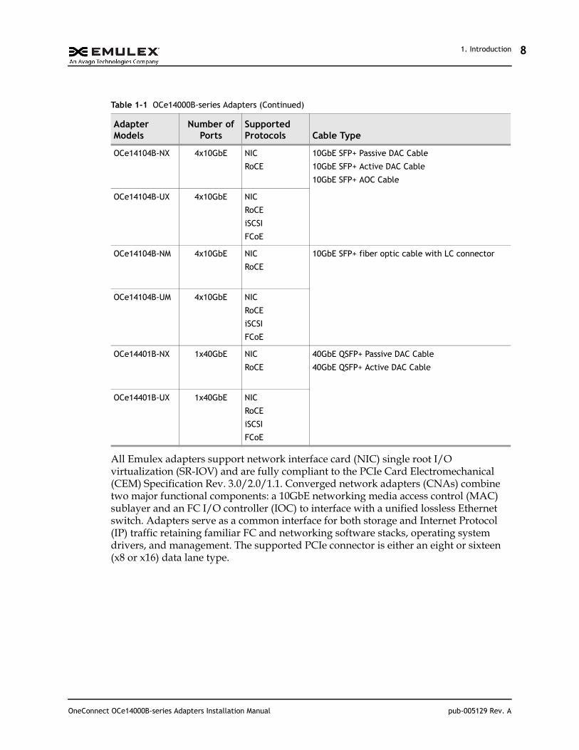
All Emulex adapters support network interface card (NIC) single root I/O virtualization (SR-IOV) and are fully compliant to the PCIe Card Electromechanical (CEM) Specification Rev. 3.0/2.0/1.1. Converged network adapters (CNAs) combine two major functional components: a 10GbE networking media access control (MAC) sublayer and an FC I/O controller (IOC) to interface with a unified lossless Ethernet switch. Adapters serve as a common interface for both storage and Internet Protocol (IP) traffic retaining familiar FC and networking software stacks, operating system drivers, and management. The supported PCIe connector is either an eight or sixteen (x8 or x16) data lane type.
OCe14104B-NX 4x10GbE NIC
RoCE
10GbE SFP+ Passive DAC Cable
10GbE SFP+ Active DAC Cable
10GbE SFP+ AOC Cable
OCe14104B-UX 4x10GbE NIC
RoCE
iSCSI
FCoE
OCe14104B-NM 4x10GbE NIC
RoCE
10GbE SFP+ fiber optic cable with LC connector
OCe14104B-UM 4x10GbE NIC
RoCE
iSCSI
FCoE
OCe14401B-NX 1x40GbE NIC
RoCE
40GbE QSFP+ Passive DAC Cable
40GbE QSFP+ Active DAC Cable
OCe14401B-UX 1x40GbE NIC
RoCE
iSCSI
FCoE
Table 1-1 OCe14000B-series Adapters (Continued)
Adapter Models
Number of Ports
Supported Protocols Cable Type
OneConnect OCe14000B-series Adapters Installation Manual pub-005129 Rev. A
1. Introduction 9
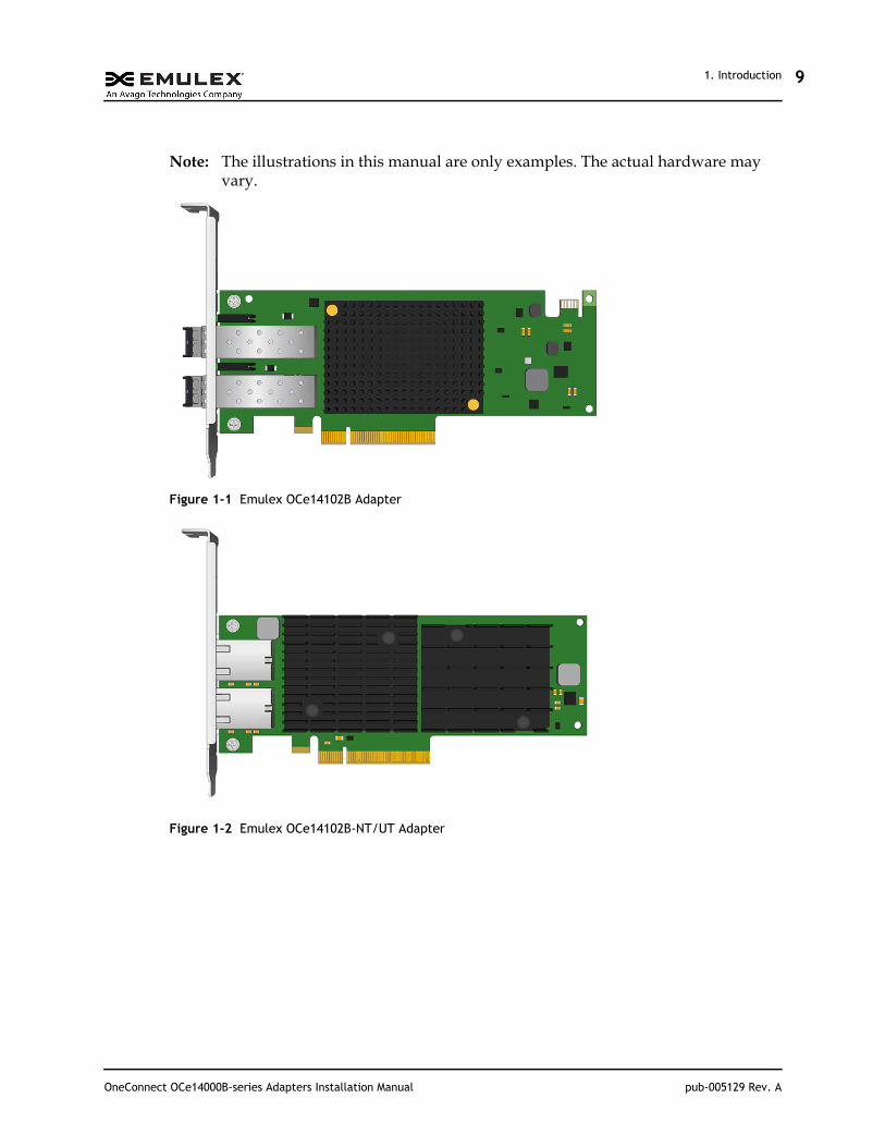
Note: The illustrations in this manual are only examples. The actual hardware may vary.
Figure 1-1 Emulex OCe14102B Adapter
Figure 1-2 Emulex OCe14102B-NT/UT Adapter
OneConnect OCe14000B-series Adapters Installation Manual pub-005129 Rev. A
1. IntroductionFeatures
10
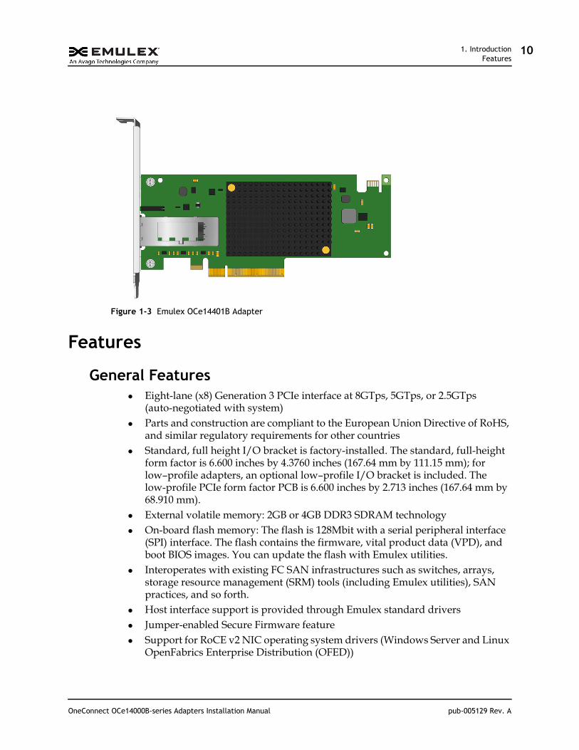
Figure 1-3 Emulex OCe14401B Adapter
Features
General Features Eight-lane (x8) Generation 3 PCIe interface at 8GTps, 5GTps, or 2.5GTps
(auto-negotiated with system) Parts and construction are compliant to the European Union Directive of RoHS,
and similar regulatory requirements for other countries Standard, full height I/O bracket is factory-installed. The standard, full-height
form factor is 6.600 inches by 4.3760 inches (167.64 mm by 111.15 mm); for low–profile adapters, an optional low–profile I/O bracket is included. The low-profile PCIe form factor PCB is 6.600 inches by 2.713 inches (167.64 mm by 68.910 mm).
External volatile memory: 2GB or 4GB DDR3 SDRAM technology On-board flash memory: The flash is 128Mbit with a serial peripheral interface
(SPI) interface. The flash contains the firmware, vital product data (VPD), and boot BIOS images. You can update the flash with Emulex utilities.
Interoperates with existing FC SAN infrastructures such as switches, arrays, storage resource management (SRM) tools (including Emulex utilities), SAN practices, and so forth.
Host interface support is provided through Emulex standard drivers Jumper-enabled Secure Firmware feature Support for RoCE v2 NIC operating system drivers (Windows Server and Linux
OpenFabrics Enterprise Distribution (OFED))
OneConnect OCe14000B-series Adapters Installation Manual pub-005129 Rev. A
1. IntroductionFeatures
11
As supported, a comprehensive array of NIC, iSCSI, FCoE, operating system drivers, including support for Windows, Linux, VMware, and Solaris.
As supported, Unified Ethernet-to-FC SAN connectivity provided by an FCoE switch.
OCe14101B Adapters Up to eight PCIe functions per adapter, individually configurable to NIC and
RoCE personalities. Low-profile PCIe form factor OCe14101B-NM - SFF-8431 Small Form Factor Pluggable (SFP+) module
compliant
OCe14102B Adapters Up to sixteen PCIe functions per adapter
OCe14102B-NX/-NM/-NT – individually configurable to NIC and RoCE personalities
OCe14102B-UX/-UM/-UT – individually configurable to NIC, RoCE, iSCSI, or FCoE personalities
Low-profile PCIe form factor OCe14102B-NM/-UM - SFF-8431 SFP+ module compliant
OCe14104B Adapters Up to sixteen PCIe functions per adapter
OCe14104B-NX/-NM - individually configurable to NIC and RoCE personalities
OCe14104B-UX/-UM - individually configurable to NIC, RoCE, iSCSI, or FCoE personalities
Standard, full-height form factor only OCe14104B-NM/-UM - SFF-8431 SFP+ module compliant
OCe14401B Adapters OCe14101B-NX and the OCe14101B-NM adapters support eight functions Up to sixteen PCIe functions per adapter, if the system supports ARI
OCe14401B-NX - individually configurable to NIC and RoCE personalities OCe14401B-UX - individually configurable to NIC, RoCE, iSCSI, or FCoE
personalities Low-profile PCIe form factor SFF-8436 compliant QSFP+ interface supporting optics and direct attach cables
OneConnect OCe14000B-series Adapters Installation Manual pub-005129 Rev. A
1. IntroductionFeatures
12
Protocol-Specific Capabilities NIC capabilities include
NDIS 5.2, 6.0, and 6.2-compliant Ethernet functionality IPv4/IPv6 TCP, UDP checksum offload IPv4/IPv6 receive-side scaling (RSS) IPv4/IPv6 large receive offload (LRO) IPv4/IPv6 large segment offload (LSO) Programmable MAC addresses Up to 128 MAC/VLAN addresses Supports hash-based multicast MAC address filters Supports hash-based broadcast frame filters per port VLAN insertion and extraction Jumbo packet support up to 9000 bytes
iSCSI capabilities include Full iSCSI protocol offload Header, data digest (CRC), and PDUs Direct data placement of SCSI data Up to 4K outstanding commands (iSCSI initiator mode only) Up to 512 offloaded iSCSI connections (iSCSI initiator mode only) iSCSI initiator and concurrent initiator/target modes Supports multipath I/O T10 PI support for end-to-end data integrity (for target mode drivers)
FCoE capabilities include Hardware offloads of Ethernet TCP/IP and concurrent iSCSI and FCoE ANSI T11 FC-BB-5 support Programmable WWN Supports FIP and FCoE ether types Concurrent logins (RPI): up to 8K per adapter Open exchanges (XRI): up to 4K per adapter FCoE initiator and target modes NPIV interfaces:
For 2x10GbE and 1x40GbE adapters, up to 255 NPIV interfaces per port For the 4x10GbE adapter, up to 127 NPIV interfaces per port T10 PI support for end-to-end data integrity (for target mode drivers)
RoCE capabilities include Direct data placement in application buffers without CPU intervention Supports IBTA RoCE specifications Supports Linux OFED
OneConnect OCe14000B-series Adapters Installation Manual pub-005129 Rev. A
1. IntroductionAdapter Identification
13
Low latency queues for small packet sends and receives Windows Server SMB Direct (SMB over RDMA)
Adapter IdentificationEach adapter has several identification numbers. Emulex recommends recording these numbers before installation.
Institute of Electrical and Electronics Engineers (IEEE) address – a unique 64-bit identifier used for system configuration
WWN – derived from the IEEE address; the FC industry uses the WWN for FC connectivity.
Serial number – assigned by Emulex and used when communicating with Emulex
If the adapter has two ports, it has two IEEE addresses and two WWNs, one for each port.
AbbreviationsAOC active optical cable
ARI alternative routing-ID interpretation
CNA Converged Network Adapter
CPU central processing unit
CRC cyclic redundancy check
DAC direct-attach copper
DDR3 double data rate type three
ESD Electrostatic Discharge
FC Fibre Channel
FCoE Fibre Channel over Ethernet
FIP FCoE Initialization Protocol
GB gigabyte
Gb gigabit
GbE gigabit Ethernet
Gbps gigabits per seconds
GTps giga transfers per second
IBTA InfiniBand Trade Association
IEEE Institute of Electrical and Electronics Engineers
IOC I/O controller
IP Internet Protocol
OneConnect OCe14000B-series Adapters Installation Manual pub-005129 Rev. A
1. IntroductionAbbreviations
14
iSCSI Internet Small Computer System Interface
LC Lucent connector
LED light-emitting diode
LRO large receive offload
LSO large segment offload
MAC Media Access Control
Mbit megabit
mm millimeters
NDIS Network Driver Interface Specification
NIC network interface card
NPIV N_Port ID Virtualization
OFED OpenFabrics Enterprise Distribution
PCBA printed circuit board assembly
PCIe Peripheral Component Interconnect Express
PCIe CEM PCIe Card Electromechanical
PDU protocol data unit
POST power-on self-test
QSFP+ Quad Small Form Factor Pluggable
RDMA remote direct memory access
RH relative humidity
RoCE RDMA over Converged Ethernet
RoHS Restriction of Hazardous Substances
RSS receive-side scaling
SAN storage area network
SDRAM synchronous dynamic random-access memory
SFP small form-factor pluggable
SMB server message block
SPI Serial Peripheral Interface
SR-IOV single root I/O virtualization
SRM storage resource management
T10 PI T10 Protection Information
TCP Transmission Control Protocol
TOR top of rack
UDP User Datagram Protocol
VLAN virtual local area network
vNIC virtual network interface card
OneConnect OCe14000B-series Adapters Installation Manual pub-005129 Rev. A

1. IntroductionAbbreviations
15
VPD vital product data
WWN World Wide Name
OneConnect OCe14000B-series Adapters Installation Manual pub-005129 Rev. A
2. InstallationPreparing the Adapter for Installation
16
2. InstallationThis section provides information on changing from the adapter bracket from a standard bracket to a low-profile adapter bracket, and installing the adapter in a computer.
Preparing the Adapter for InstallationBefore installing the adapter, you may need to perform one or both of the following procedures:
Change the bracket from a full-height to the low-profile version by following the instructions in “Changing the Bracket”.
Disable the Secure Firmware feature found on some OCe14000B-series adapter models by following the instructions in “Enabling or Disabling the Secure Firmware Feature” on page 18.
If these procedures are not applicable, proceed to “Installing the Adapter” on page 20.
Changing the BracketA standard, full-height PCIe bracket is factory-installed; however, a low-profile bracket is included in the box with the adapter (except for the OCe14104B adapter, which cannot use the low-profile bracket).
To change the adapter from a full-height to a low-profile bracket:
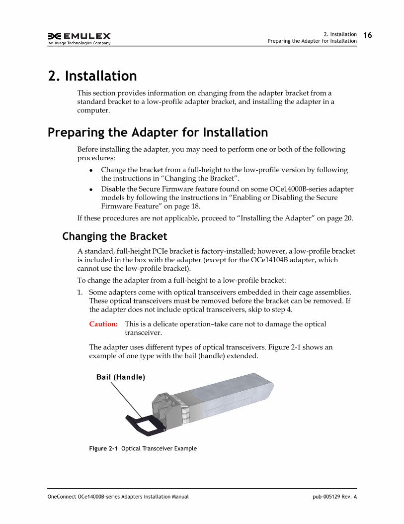
1. Some adapters come with optical transceivers embedded in their cage assemblies. These optical transceivers must be removed before the bracket can be removed. If the adapter does not include optical transceivers, skip to step 4.
Caution: This is a delicate operation–take care not to damage the optical transceiver.
The adapter uses different types of optical transceivers. Figure 2-1 shows an example of one type with the bail (handle) extended.
Figure 2-1 Optical Transceiver Example
OneConnect OCe14000B-series Adapters Installation Manual pub-005129 Rev. A
2. InstallationPreparing the Adapter for Installation
17
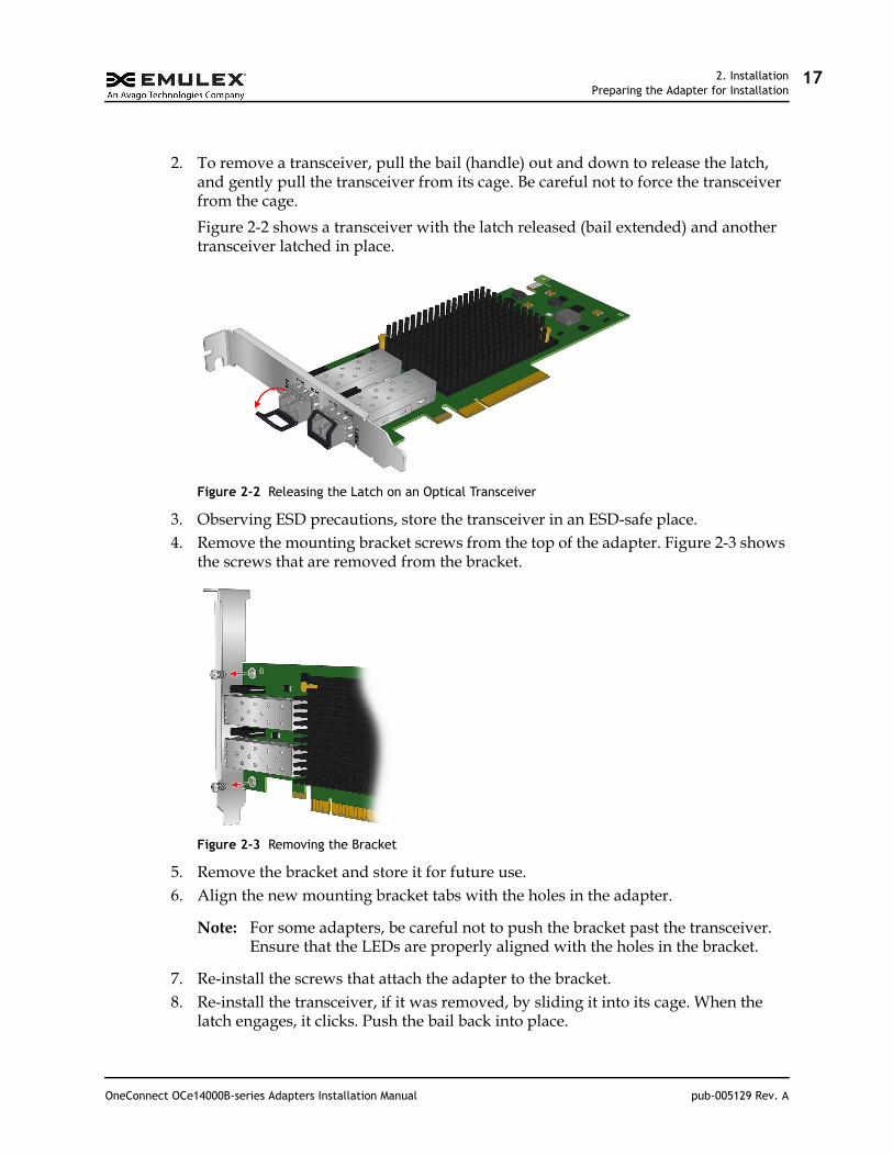
2. To remove a transceiver, pull the bail (handle) out and down to release the latch, and gently pull the transceiver from its cage. Be careful not to force the transceiver from the cage.
Figure 2-2 shows a transceiver with the latch released (bail extended) and another transceiver latched in place.
Figure 2-2 Releasing the Latch on an Optical Transceiver
3. Observing ESD precautions, store the transceiver in an ESD-safe place.4. Remove the mounting bracket screws from the top of the adapter. Figure 2-3 shows
the screws that are removed from the bracket.
Figure 2-3 Removing the Bracket
5. Remove the bracket and store it for future use.6. Align the new mounting bracket tabs with the holes in the adapter.
Note: For some adapters, be careful not to push the bracket past the transceiver. Ensure that the LEDs are properly aligned with the holes in the bracket.
7. Re-install the screws that attach the adapter to the bracket.8. Re-install the transceiver, if it was removed, by sliding it into its cage. When the
latch engages, it clicks. Push the bail back into place.
OneConnect OCe14000B-series Adapters Installation Manual pub-005129 Rev. A
2. InstallationPreparing the Adapter for Installation
18
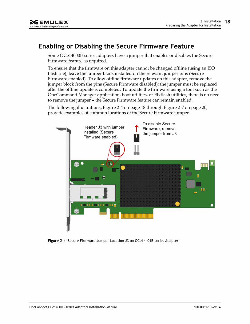
Enabling or Disabling the Secure Firmware FeatureSome OCe14000B-series adapters have a jumper that enables or disables the Secure Firmware feature as required.
To ensure that the firmware on this adapter cannot be changed offline (using an ISO flash file), leave the jumper block installed on the relevant jumper pins (Secure Firmware enabled). To allow offline firmware updates on this adapter, remove the jumper block from the pins (Secure Firmware disabled); the jumper must be replaced after the offline update is completed. To update the firmware using a tool such as the OneCommand Manager application, boot utilities, or Elxflash utilities, there is no need to remove the jumper – the Secure Firmware feature can remain enabled.
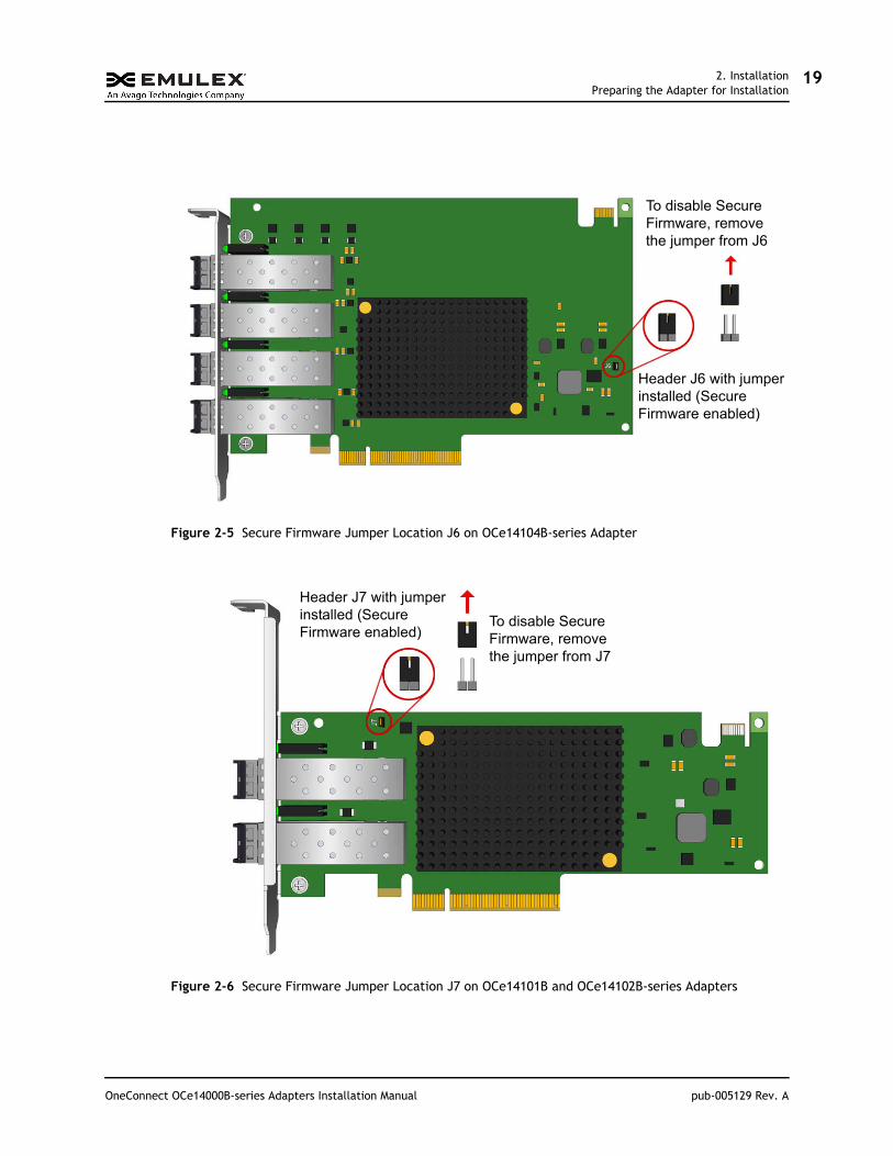
The following illustrations, Figure 2-4 on page 18 through Figure 2-7 on page 20, provide examples of common locations of the Secure Firmware jumper.
Figure 2-4 Secure Firmware Jumper Location J3 on OCe14401B-series Adapter
Header J3 with jumper installed (Secure Firmware enabled)
To disable Secure Firmware, remove the jumper from J3
OneConnect OCe14000B-series Adapters Installation Manual pub-005129 Rev. A
2. InstallationPreparing the Adapter for Installation
19
Figure 2-5 Secure Firmware Jumper Location J6 on OCe14104B-series Adapter
Figure 2-6 Secure Firmware Jumper Location J7 on OCe14101B and OCe14102B-series Adapters
Header J6 with jumper installed (Secure Firmware enabled)
To disable Secure Firmware, remove the jumper from J6
Header J7 with jumper installed (Secure Firmware enabled)
To disable Secure Firmware, remove the jumper from J7
OneConnect OCe14000B-series Adapters Installation Manual pub-005129 Rev. A
2. InstallationInstalling the Adapter
20
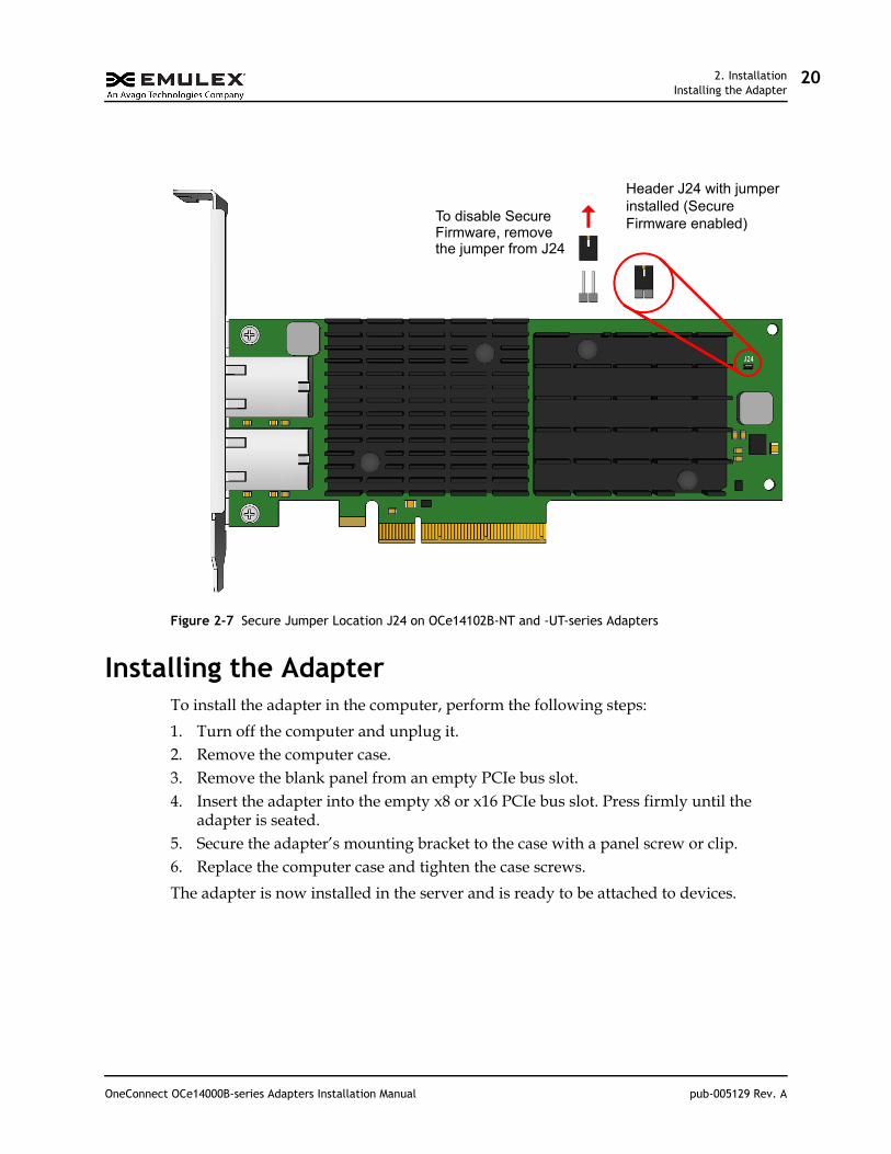
Figure 2-7 Secure Jumper Location J24 on OCe14102B-NT and -UT-series Adapters
Installing the AdapterTo install the adapter in the computer, perform the following steps:
1. Turn off the computer and unplug it.2. Remove the computer case.3. Remove the blank panel from an empty PCIe bus slot.4. Insert the adapter into the empty x8 or x16 PCIe bus slot. Press firmly until the
adapter is seated.5. Secure the adapter’s mounting bracket to the case with a panel screw or clip.6. Replace the computer case and tighten the case screws.
The adapter is now installed in the server and is ready to be attached to devices.
Header J24 with jumper installed (Secure Firmware enabled)
To disable SecureFirmware, removethe jumper from J24
OneConnect OCe14000B-series Adapters Installation Manual pub-005129 Rev. A
3. Attaching Devices to the AdapterConnecting Devices to Adapters Using a DAC or AOC Cable
21
3. Attaching Devices to the AdapterThe following sections describe how to connect devices to the adapter using different cable types.
Connecting Devices to Adapters Using a DAC or AOC Cable
The following adapters can be connected to a DAC or AOC cable:
OCe14101B-NX OCe14102B-NX OCe14102B-UX OCe14104B-NX OCe14104B-UX OCe14401B-NX OCe14401B-UX
An adapter does not allow normal data transmission on a copper link unless it is connected to a compatible copper interface connection. The cable and connector specifications are listed in Table 3-1 and Table 3-2.
To attach devices to the adapter:
1. Connect the cable to the adapter. When connecting a DAC or AOC cable, ensure that the SFP+ cages do not have optical transceivers installed in them. To remove optical transceivers, see “Preparing the Adapter for Installation” on page 16.
Table 3-1 OCe14101B-NX, OCe14102B-NX/-UX, and OCe14104B-NX/-UX Cable and Connector Specifications
Cable TypeMaximum Length
(meters)Minimum
Length (meters) Connector
10GbE SFP+ Passive DAC Cable 5 0.5 DAC
10GbE SFP+ Active DAC Cable 10 0.5 DAC
10GbE SFP+ Active Optical Cable 7 1 AOC
Table 3-2 OCe14401B-NX/-UX Cable and Connector Specifications
Cable TypeMaximum Length
(meters)Minimum
Length (meters) Connector
40GbE QSFP+ Passive DAC Cable 5 0.5 DAC
40GbE QSFP+ Active DAC Cable 10 0.5 DAC
OneConnect OCe14000B-series Adapters Installation Manual pub-005129 Rev. A
3. Attaching Devices to the AdapterConnecting Devices to Adapters Using a DAC or AOC Cable
22
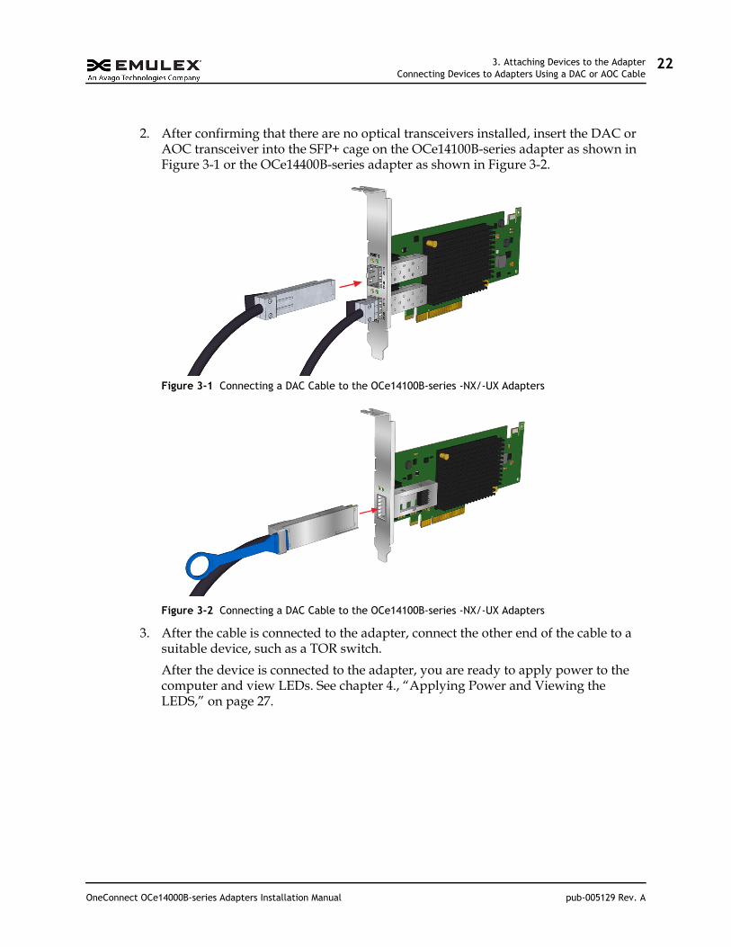
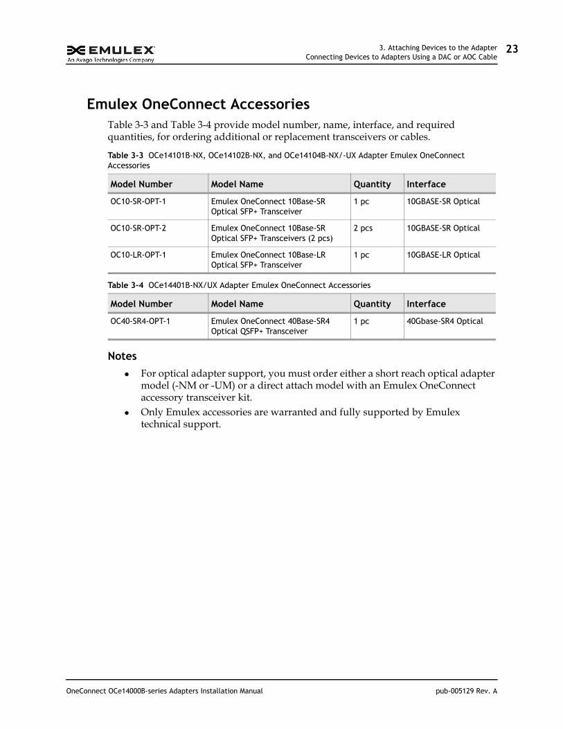
2. After confirming that there are no optical transceivers installed, insert the DAC or AOC transceiver into the SFP+ cage on the OCe14100B-series adapter as shown in Figure 3-1 or the OCe14400B-series adapter as shown in Figure 3-2.
Figure 3-1 Connecting a DAC Cable to the OCe14100B-series -NX/-UX Adapters
Figure 3-2 Connecting a DAC Cable to the OCe14100B-series -NX/-UX Adapters
3. After the cable is connected to the adapter, connect the other end of the cable to a suitable device, such as a TOR switch.
After the device is connected to the adapter, you are ready to apply power to the computer and view LEDs. See chapter 4., “Applying Power and Viewing the LEDS,” on page 27.
OneConnect OCe14000B-series Adapters Installation Manual pub-005129 Rev. A
3. Attaching Devices to the AdapterConnecting Devices to Adapters Using a DAC or AOC Cable
23
Emulex OneConnect AccessoriesTable 3-3 and Table 3-4 provide model number, name, interface, and required quantities, for ordering additional or replacement transceivers or cables.
Notes
For optical adapter support, you must order either a short reach optical adapter model (-NM or -UM) or a direct attach model with an Emulex OneConnect accessory transceiver kit.
Only Emulex accessories are warranted and fully supported by Emulex technical support.
Table 3-3 OCe14101B-NX, OCe14102B-NX, and OCe14104B-NX/-UX Adapter Emulex OneConnect Accessories
Model Number Model Name Quantity Interface
OC10-SR-OPT-1 Emulex OneConnect 10Base-SR Optical SFP+ Transceiver
1 pc 10GBASE-SR Optical
OC10-SR-OPT-2 Emulex OneConnect 10Base-SR Optical SFP+ Transceivers (2 pcs)
2 pcs 10GBASE-SR Optical
OC10-LR-OPT-1 Emulex OneConnect 10Base-LR Optical SFP+ Transceiver
1 pc 10GBASE-LR Optical
Table 3-4 OCe14401B-NX/UX Adapter Emulex OneConnect Accessories
Model Number Model Name Quantity Interface
OC40-SR4-OPT-1 Emulex OneConnect 40Base-SR4 Optical QSFP+ Transceiver
1 pc 40Gbase-SR4 Optical
OneConnect OCe14000B-series Adapters Installation Manual pub-005129 Rev. A
3. Attaching Devices to the AdapterConnecting Devices to Adapters Using an Optical Cable with LC Connectors
24
Connecting Devices to Adapters Using an Optical Cable with LC Connectors
The following adapters can be connected to a fiber optic cable with an embedded optical transceiver:
OCe14101B-NM OCe14102B-NM OCe14102B-UM OCe14104B-NM OCe14104B-UM
The cable and connector specifications are listed in Table 3-1 on page 21. For AOC cables see Table 3-6 on page 26.
Table 3-5 OCe14101B-NM, OCe14102B-NM/-UM, and OCe14104B-NM/-UM Adapter Cable and Connector Specifications
Cable TypeMaximum
Length (meters)Minimum
Length (meters) Connector
Fiber Optic Cable (Ethernet Only)
Long Range, LC-LC Single Mode Fiber (SMF)10 Gb per second (Gbps)
10,000 2 LC
OM3 – Multimode 50/125 micron fiber (2000 MHz*km bandwidth cable) with LC connectors:
1 Gbps (Not specified by IEEE 802.3)
10 Gbps550
300
2
2
LC
LC
OM2 - Multimode 50/125 micron fiber (500 MHz*km bandwidth cable) with LC connectors:
1 Gbps
10 Gbps550
82
2
2
LC
LC
OM1 - Multimode 62.5/125 micron fiber (200 MHz*km bandwidth cable) with LC connectors:
1 Gbps
10 Gbps275
26
2
2
LC
LC
OneConnect OCe14000B-series Adapters Installation Manual pub-005129 Rev. A
3. Attaching Devices to the AdapterConnecting Devices to Adapters Using an Optical Cable with LC Connectors
25
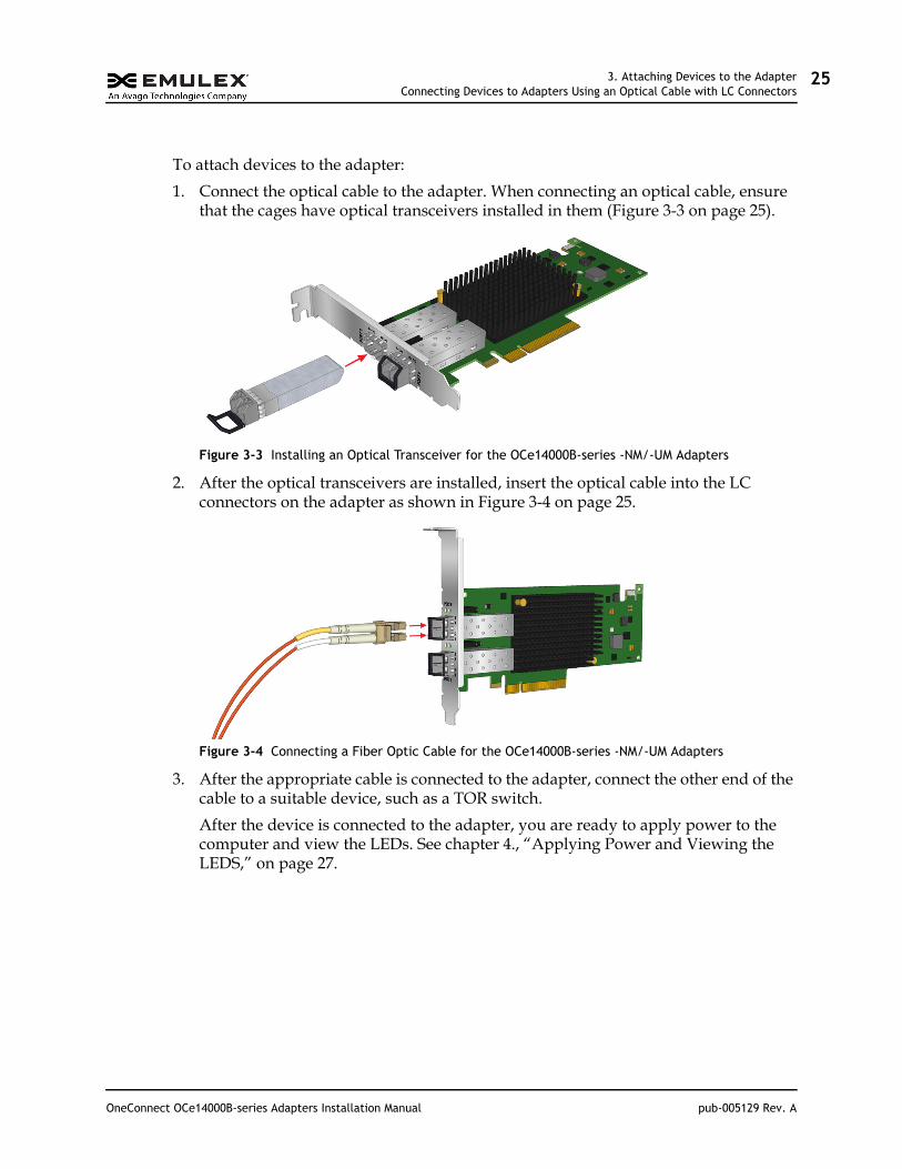
To attach devices to the adapter:
1. Connect the optical cable to the adapter. When connecting an optical cable, ensure that the cages have optical transceivers installed in them (Figure 3-3 on page 25).
Figure 3-3 Installing an Optical Transceiver for the OCe14000B-series -NM/-UM Adapters
2. After the optical transceivers are installed, insert the optical cable into the LC connectors on the adapter as shown in Figure 3-4 on page 25.
Figure 3-4 Connecting a Fiber Optic Cable for the OCe14000B-series -NM/-UM Adapters
3. After the appropriate cable is connected to the adapter, connect the other end of the cable to a suitable device, such as a TOR switch.
After the device is connected to the adapter, you are ready to apply power to the computer and view the LEDs. See chapter 4., “Applying Power and Viewing the LEDS,” on page 27.
OneConnect OCe14000B-series Adapters Installation Manual pub-005129 Rev. A
3. Attaching Devices to the AdapterConnecting Devices to Adapters Using a UTP or CAT Cable
26
Connecting Devices to Adapters Using a UTP or CAT Cable
The OCe14102B-NT and OCe14102B-UT adapters can be connected with an unshielded twisted pair (UTP) or shielded twisted pair (STP) copper cable (commonly referred to as a Category or 'CAT' cable).
The cable and connector specifications are listed in Table 3-6.
To attach devices to the adapter:
1. Connect one end of the CAT cable to the 10GBase-T adapter.2. After the appropriate cable is connected to the adapter, connect the other end of the
cable to a suitable device, such as a TOR switch or female RJ45 patch panel.3. After the device is connected to the adapter, you are ready to apply power to the
system and view the LEDs. See chapter 4., “Applying Power and Viewing the LEDS,” on page 27.
Table 3-6 OCe14102B-NT/-UT Adapter Cable and Connector Specifications
Cable Type Maximum Length Connector
CAT 6 STP, CAT 6A UTP/STP, CAT 7 STP in 10G mode
100 meters (328 feet) RJ-45
CAT 6 UTP (screened) in 10G mode 55 meters (180 feet RJ-45
CAT 5E (or higher category cable) in 1G (1000BASE-T) mode
100 meters (328 feet) RJ-45
OneConnect OCe14000B-series Adapters Installation Manual pub-005129 Rev. A

4. Applying Power and Viewing the LEDSApplying Power
27
4. Applying Power and Viewing the LEDSThis section provides instructions on how to apply power and how to interpret the LEDs for various adapter models.
Applying PowerTo apply power:
1. Verify that the adapter is securely installed in the system.2. Verify that the correct device is attached.3. Plug in and turn on the system.4. Observe the boot banner for POST results.
LED Indicators
OCe14102B-NT/UT Adapters
Dual Color Amber/Green LED (Link Status)
On (constantly green) = Link up at 1000BASE-T On (constantly amber) = Link up at 10GBASE-T Off = Link down
Green LED (Ethernet Activity)
Blink = Activity on the Ethernet link Off = No activity on the Ethernet link
All Other OCe14000B-series Adapters
Amber LED (Link Status)
On (constantly) = Link up Off = Link down
Green LED (Ethernet Activity)
Blink = Activity on the Ethernet link
Off = No activity on the Ethernet link
OneConnect OCe14000B-series Adapters Installation Manual pub-005129 Rev. A
4. Applying Power and Viewing the LEDSViewing the LEDs
28
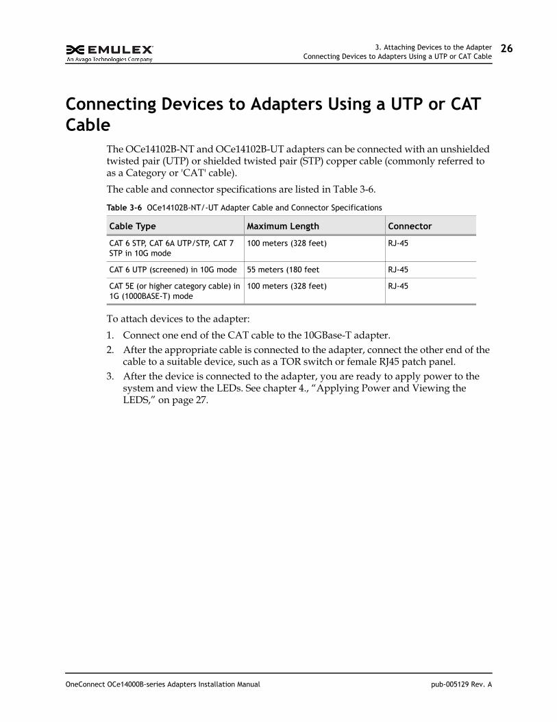
Viewing the LEDsThe LED indicators in Figure 4-1 pertain to the following adapter models:
OCe14101B-NM/-NX OCe14102B-NM/-NX OCe14102B-UX/-UM
Each port connector has one amber and one green LED.
Figure 4-1 OCe14101B-NM/-NX, OCe14102B-NM/-NX, and OCe14102B-UX/-UM Adapter LED Indicators
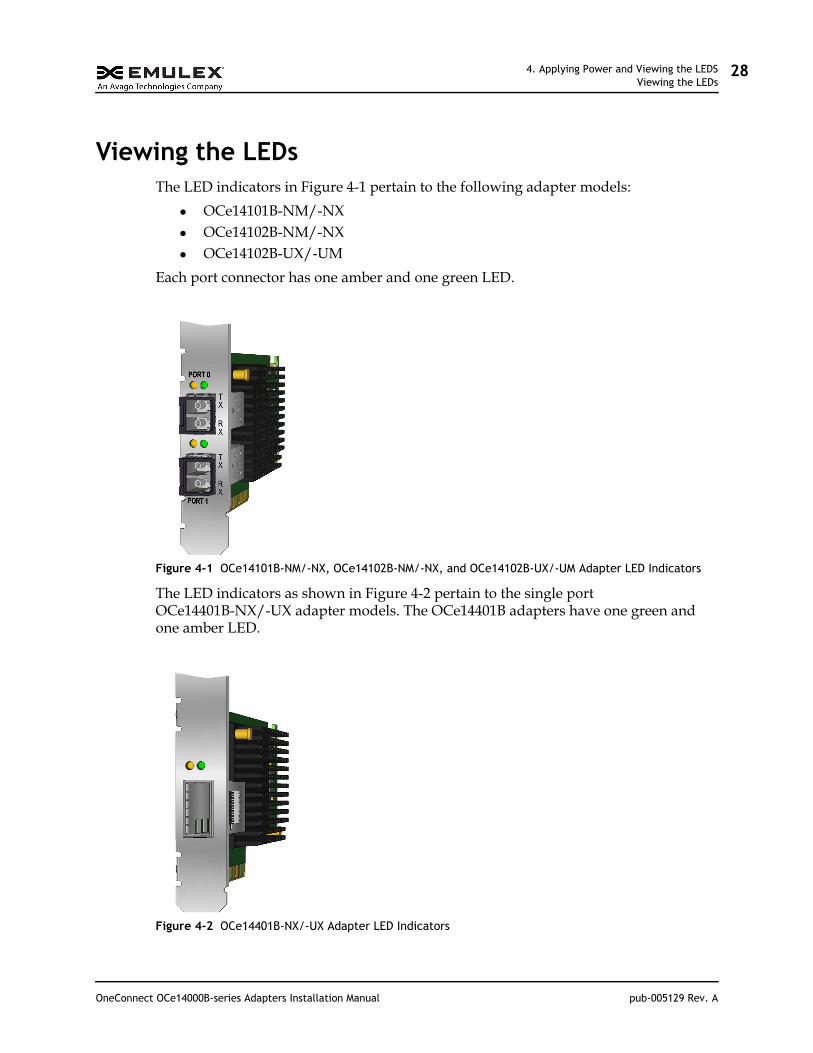
The LED indicators as shown in Figure 4-2 pertain to the single port OCe14401B-NX/-UX adapter models. The OCe14401B adapters have one green and one amber LED.
Figure 4-2 OCe14401B-NX/-UX Adapter LED Indicators
OneConnect OCe14000B-series Adapters Installation Manual pub-005129 Rev. A
4. Applying Power and Viewing the LEDSViewing the LEDs
29
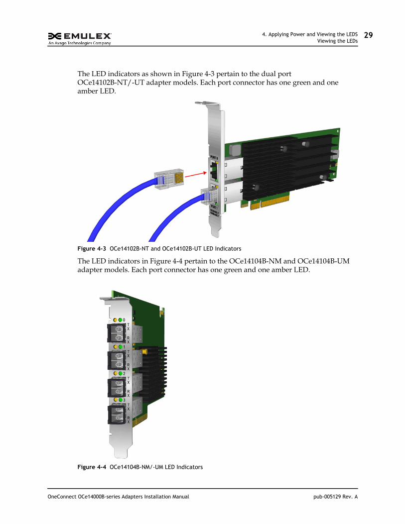
The LED indicators as shown in Figure 4-3 pertain to the dual port OCe14102B-NT/-UT adapter models. Each port connector has one green and one amber LED.
Figure 4-3 OCe14102B-NT and OCe14102B-UT LED Indicators
The LED indicators in Figure 4-4 pertain to the OCe14104B-NM and OCe14104B-UM adapter models. Each port connector has one green and one amber LED.
Figure 4-4 OCe14104B-NM/-UM LED Indicators
OneConnect OCe14000B-series Adapters Installation Manual pub-005129 Rev. A
5. ReferencesSpecifications
30
5. References
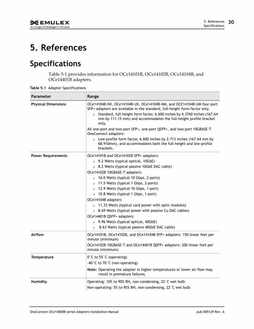
SpecificationsTable 5-1 provides information for OCe14101B, OCe14102B, OCe14104B, and OCe14401B adapters.
Table 5-1 Adapter Specifications
Parameter Range
Physical Dimensions OCe14104B-NX, OCe14104B-UX, OCe14104B-NM, and OCE14104B-UM four-port SFP+ adapters are available in the standard, full-height form factor only.
Standard, full-height form factor, 6.600 inches by 4.3760 inches (167.64 mm by 111.15 mm) and accommodates the full-height profile bracket only.
All one-port and two-port SFP+, one-port QSFP+, and two-port 10GBASE-T OneConnect adapters:
Low-profile form factor, 6.600 inches by 2.713 inches (167.64 mm by 68.910mm), and accommodates both the full-height and low-profile brackets.
Power Requirements OCe14101B and OCe14102B SFP+ adapters: 9.2 Watts (typical optical, 10GbE) 8.2 Watts (typical passive 10GbE DAC cable)
OCe14102B 10GBASE-T adapters: 16.0 Watts (typical 10 Gbps, 2-ports) 11.5 Watts (typical 1 Gbps, 2-ports) 12.9 Watts (typical 10 Gbps, 1-port) 10.8 Watts (typical 1 Gbps, 1-port)
OCe14104B adapters 11.33 Watts (typical card power with optic modules) 8.69 Watts (typical power with passive Cu DAC cables)
OCe14401B QSFP+ adapters: 9.96 Watts (typical optical, 40GbE) 8.63 Watts (typical passive 40GbE DAC cable)
Airflow OCe14101B, OCe14102B, and OCe14104B SFP+ adapters: 150 linear feet per minute (minimum)
OCe14102B 10GBASE-T and OCe14401B QSFP+ adapters: 200 linear feet per minute (minimum)
Temperature 0°C to 55°C (operating)
-40°C to 70°C (non-operating)
Note: Operating the adapter in higher temperatures or lower air flow may result in premature failures.
Humidity Operating: 10% to 90% RH, non-condensing, 22°C wet bulb
Non-operating: 5% to 95% RH, non-condensing, 22°C wet bulb
OneConnect OCe14000B-series Adapters Installation Manual pub-005129 Rev. A
5. ReferencesFCC and Regulatory Notices
31
FCC and Regulatory Notices
OCe14000B-series Adapters
This device complies with Part 15 of the FCC Rules. Operation is subject to the following two conditions: (1) This device may not cause harmful interference, and (2) this device must accept any interference received, including interference that may cause undesired operation.
Responsible Party:
Jeff Benck, President and Chief Executive Officer
Emulex Corporation (714) 662-5600
3333 Susan St. Costa Mesa, CA. 92626 USA
Note: This equipment has been tested and found to comply with the limits for a Class A digital device, pursuant to part 15 of the FCC Rules. These limits are designed to provide reasonable protection against harmful interference when the equipment is operated in a commercial environment. This equipment generates, uses, and can radiate radio frequency energy and, if not installed and used in accordance with the instruction manual, may cause harmful interference to radio communications. Operation of this equipment in a residential area is likely to cause harmful interference in which case the user will be required to correct the interference at his own expense. The reader is cautioned that changes or modifications made to the equipment not
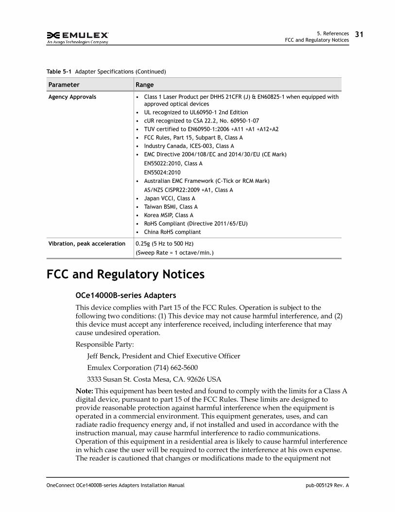
Agency Approvals • Class 1 Laser Product per DHHS 21CFR (J) & EN60825-1 when equipped with approved optical devices
• UL recognized to UL60950-1 2nd Edition• cUR recognized to CSA 22.2, No. 60950-1-07• TUV certified to EN60950-1:2006 +A11 +A1 +A12+A2• FCC Rules, Part 15, Subpart B, Class A• Industry Canada, ICES-003, Class A• EMC Directive 2004/108/EC and 2014/30/EU (CE Mark)
EN55022:2010, Class A
EN55024:2010• Australian EMC Framework (C-Tick or RCM Mark)
AS/NZS CISPR22:2009 +A1, Class A• Japan VCCI, Class A• Taiwan BSMI, Class A• Korea MSIP, Class A • RoHS Compliant (Directive 2011/65/EU)• China RoHS compliant
Vibration, peak acceleration 0.25g (5 Hz to 500 Hz)
(Sweep Rate = 1 octave/min.)
Table 5-1 Adapter Specifications (Continued)
Parameter Range
OneConnect OCe14000B-series Adapters Installation Manual pub-005129 Rev. A

5. ReferencesFCC and Regulatory Notices
32
expressly approved by Emulex could void the user's authority to operate this equipment. The above statement applies to products marketed in the USA.
This class A digital apparatus meets all requirements of the Industry Canada (IC) Interference - Causing Equipment Standard (ICES-003).
Cet appareil numérique de la classe A respecte toutes les exigences du règlement sur le matériel brouilleur du Canada. CAN ICES-3 (A)/ NMB-3 (A)
Notice for Japan and Translations (VCCI)
Translation:
This is a Class A product. If this equipment is used in a domestic environment, radio interference may occur, in which case, the user may be required to take corrective action. VCCI—A.
Notice for Taiwan and Translations (BSMI)
Translation:
This equipment is a Class A ITE, and operation of this equipment in a residential area is likely to cause harmful interference, in which case users will be required to correct the interference at their own expense.
Notice for South Korea and Translations (MSIP)
Translation:
Sellers and users of this equipment take note that this equipment is EMC approved for Class A industrial use, and as such is not intended for residential use.
OneConnect OCe14000B-series Adapters Installation Manual pub-005129 Rev. A

5. ReferencesDeclaration of Conformity
33
Declaration of Conformity
OCe14000B-series Adapters
This equipment complies with CISPR22/EN55022 Class A.
WARNING: This is a class A product. In a domestic environment, this product may cause radio interference requiring the user to take adequate measures.
OneConnect OCe14000B-series Adapters Installation Manual pub-005129 Rev. A

5. ReferencesLaser Safety Notice
34
Note: Changes or modifications not expressly approved by Emulex Corporation, including the use of non-Emulex approved optical transceivers, could void the user's authority to operate this equipment.
Laser Safety NoticeEmulex products incorporating optical laser transceivers contain Class 1 laser devices, which comply with DHHS/CDRH 21CFR Sub-chapter J, and the international laser safety standard EN/IEC 60825-1. Class 1 laser devices are not considered to be hazardous.
DECLARATION OF CONFORMITY Manufacturer: Emulex Corporation
3333 Susan StreetCosta Mesa, CA. 92626 USA
declares under sole responsibility that the product:
Product Name: OneConnect® UCNARegulatory Model: P008827, P008933, P009956, P010215Assembly Number: P008827 xxx, P008933 xxx, P009956 xxx, P010215 xxx (x=alphanumeric)
To which this Declaration relates is in conformity with the following standards or other documents forInformation Technology Equipment (ITE):
Product Safety: Electromagnetic Compatibility (Class A):UL Recognized to UL 60950 1:2007, Second EditioncUR Recognized to CSA 22.2, No. 60950 1 07IEC 60950 1:2005 +A1 +A2 (CB Scheme)EN 60950 1:2006 +A11 +A1 +A12 +A2EN 60825 1:2007*CFR Title 21, Laser AEL Class 1, FDA/CDRH** when equipped with approved optical transceivers
FCC Rules, CFR Title 47, Part 15, Subpart BIndustry Canada, ICES 003:2012 (Issue 5)EN55022:2010 / CISPR 22:2008EN55024:2010 / CISPR 24:2010AS/NZS CISPR22:2009+A1VCCI:2014CNS 13438:2006 (complete), KN22, KN24
Hazardous Substances:The object of this declaration described above is in conformity with Directive 2011/65/EU of the EuropeanParliament and of the Council of 8 June 2011 on the restriction of the use of certain hazardous substances inelectrical and electronic equipment, and has been validated per EN 50581:2012.
SupplementaryInformation:
1. The product was tested in a typical configuration.2. The product is in compliance with the following directives:
European Union Low Voltage Directives 2006/95/EC and 2014/35/EUEuropean Union EMC Directives 2004/108/EC and 2014/30/EUEuropean Union RoHS Directive 2011/65/EUAustralian RCM framework
May 13, 2015Costa Mesa, CA Jeff Benck
President and Chief Executive Officer
European Contact: Emulex Ireland CompanyPlaza 255, Blanchardstown Corporate Park 2, +353 (0)1 652 1700Ballycoolin, Dublin 15 Ireland www.emulex.com
OneConnect OCe14000B-series Adapters Installation Manual pub-005129 Rev. A

5. ReferencesLaser Safety Notice
35
The use of non-Emulex approved optical transceivers, or transceivers which do not comply with the Class 1 radiation performance requirements defined in DHHS/CDRH 21CFR Sub-chapter J and IEC 60825-1, may expose the user to hazardous laser radiation, and such devices should not be used with Emulex products.
OneConnect OCe14000B-series Adapters Installation Manual pub-005129 Rev. A