Embed Size (px)
Citation preview

Our new Hydronex™ Panels come in three main configurations: P-Series, D-Series, and Z-Series.The 35 standard models can be customized, with control and circulator options available. P-Series and D-Series Panels feature the Rail Mount enclosure while Z-Series Panels feature a Box Mount enclosure.• Cost-effective• Fast delivery • Quick installation • 35 standard models; more
with custom options • Linked together or stand-alone • Contractor-friendly • Three circulator brand options
4500 E. Progress Place Springfield, MO 65803-8816USA & Canada: 800-276-2419 Phone: 417-864-6108 Fax: 417-864-8161
See our Radiant Catalog online at: www.wattsradiant.com
O n i x w i t h A l u m a S h i e l d C o m p a r e d w i t h E V O H B a r r i e r P E XTubing Proper t ies Onix Barrier PEXFlexibility flexible even in subfreezing temperatures larger bend radius, stiff below 40°FAbrasion highly abrasion resistant susceptible to abrasion from metal, fasteners or sharp fillSunlight not affected by exposure damaged if exposed for more than a few weeksKinking not damaged by kinking must be replaced or repaired if kinkedTemperature functional from –35°F to +180°F easily damaged in cold Flame resistance highly flame resistant burns easilyStress cracking not affected by stress cracking damaged by physical impact and other stress
Barr ier Proper t ies AlumaShield™ EVOHMoisture not damaged by moisture performance lessened by exposure to moistureHeat not damaged by heat permanent performance loss by 160°F+ exposureSunlight not damaged by UV radiation damaged by more than a few weeks of sunlight
®
CustomCut™ ManifoldsSwedged Manifolds
Copyright © 2005 Watts Radiant, Inc. Onix Installation Manual LIT#ONIXMAN0505 Effective: 05/01/2005
A v a i l a b l e S i z e s :Onix is available in the following nominal I.D.: 3/8", 1/2", 5/8", 3/4", and 1".
Introducing
Modular Control Panels
To learn more about Hydronex panels call 800-276-2419, or go to www.wattsradiant.com and click on the Hydronex link.
Protective pin-mounted cover included.
O n i x M a n i f o l d s : Watts Radiant offers a wide range of
manifolds for Onix. Manifold accessories include unions, isolation valves, temperature gauges, vent-and-purge assemblies, and flow meters. Additional specifications can be found in the Watts Radiant Onix Submittal or the Watts Radiant full-line Product Catalog.
Stainless Steel Manifolds
Onix is tested to relevant portions of several ASTM standards, carries the BOCAcertification mark as approved by BOCA research report number 95-47.1, and carriesthe UPC mark as approved by the International Association of Plumbing and Mechani-cal Officials. Watts Radiant is a charter member of the Radiant Panel Association.

This Onix Installation Manual represents the
collective knowledge of thousands of our cus-
tomers who have been kind enough to furnish us
with ideas and techniques that have worked for
them. We have selected the best of these ideas
and rigorously refined them.
This refining process is based on the collective
wisdom that comes from having an engineering
and technical staff with over 200 years of
combined experience with modern floor heating
and snowmelting. Please take the time to
carefully read this manual before installing your
floor heating or snowmelting system.
PLEASE NOTE:
This manual only covers installation of Watts Radiant’s
Onix hose, and should not be used for the installation of
our cross-linked polyethylene products, RadiantPEX® and
WaterPEX®.
This is not a design manual. For design assistance, we
encourage you to contact us or our representatives for a
design analysis using Watts Radiant’s RadiantWorks®
system design software.
Before designing or installing a radiant heating or snow-
melting sytstem, you should always consult with local,
experienced design and installation professionals to ensure
compliance with local building practices, climate conditions,
state and local building codes, and past customs.
Used when placing a new radiant slab directly over an existing slab. A great application when the slab will be subjected to heavy loads.
Where space permits, we recommend the use of extruded polystyrene(Dow¤ Blue Board¤ ) insulation at the perimeter of the new slab.
The use of poly-fiber material in the new concrete slab will add crackresistance.
In this application the Onix can be tied to rewire or poultry nettingdepending on the structural needs of the project.
Slab over Existing Slab
Fasten the Onix in place and then cover it with a minimum of 2" of portland concrete mix above the top of the Onix. More may be required depending on structural loading.
Use a foil-faced insulation for this application, with the foil facing up, anda 2" minimum air space between the foil surface and the steel deck.
Sprayed-on insulation also works well in this application.
Slab over Steel Deck
This is the most popular application in snow-melting and it provides the best snowmelting performance.
Install Onix midway in the slab or at a depth that will provide a minimumof 3" of concrete over the top of the Onix. More may be required depend-ing on structural loading.
The size and spacing of Onix varies widely in snowmelting projects and isbased on many variables. Always refer to specific design information forthe project.
Drainage is important in snowmelting. Make sure provisions are made tosafely carry away the melt water.
Note that insulation is not required in this application.
Typical Slab Snowmelt
This is a popular choice when brick pavers are being installed in an entrance, courtyard, driveway or other outdoor area where snow and ice removal is needed.
Onix is installed in a sand or crushed stone base, then secured with wirehooks every two feet along its length. A layer of sand is then placed overthe Onix and compacted to provide a minimum of 1" coverage above thetop of the Onix (more may be required depending on structural loading).The brick pavers are then installed on the compacted base material.
The size and spacing of Onix varies widely in snowmelting projects and isbased on many variables. Always refer to specific design information forthe project. Drainage is important in snowmelting. Make sure provisionsare made to safely carry away the melt water.
Note that insulation is not required in this application.
Brick Paver Snowmelt
Warm up a concrete slab to provide space heat.
Install a minimum of 2" ofconcrete above the top of the Onix for residential and 3" for commercial floor heatapplications.You may need a greater thickness over the Onix, depending on structural loading.
Use an extruded polystyrene (Dow¤ Blue Board¤ ) insulation board on the edge of, and optionally under the slab, depending on site conditions.
Slab on Grade
Snowmelting Applications


page 2 Watts Radiant: Onix Installation Manual
Table of ContentsSection Page
Introduction . . . . . . . . . . . . . . . . . . . . . . . . . . . . . . . . . .6Heat Transfer Basics . . . . . . . . . . . . . . . . . . . . . . . . . . .6Onix™ Radiant Piping . . . . . . . . . . . . . . . . . . . . . . . . . .6The Design Process . . . . . . . . . . . . . . . . . . . . . . . . . . . .7
Step 1: Initial Design Considerations . . . . . . . . . . . . . .8Floor Coverings . . . . . . . . . . . . . . . . . . . . . . . . . . . .8
Tile Floors . . . . . . . . . . . . . . . . . . . . . . . . . . . . . . .9Hardwood Flooring . . . . . . . . . . . . . . . . . . . . . . . .9
Controlling Moisture . . . . . . . . . . . . . . . . . . . . .10Installation Cautions . . . . . . . . . . . . . . . . . . . . .11
Carpet and Pad Flooring . . . . . . . . . . . . . . . . . . .12Step 2: Radiant Zoning . . . . . . . . . . . . . . . . . . . . . . . .12
1. Zoned by Floor Coverings . . . . . . . . . . . . . . . . .122. Zoned by Occupancy . . . . . . . . . . . . . . . . . . . . .123. Zoned by Construction . . . . . . . . . . . . . . . . . . . .124. Zoned by Mechanical Considerations . . . . . . . .12
Step 3: Manifold Location . . . . . . . . . . . . . . . . . . . . .13Step 4: Heat Loss Calculations . . . . . . . . . . . . . . . . . .14
Using RadiantWorks® Reports . . . . . . . . . . . . . . . .14Zone List Report . . . . . . . . . . . . . . . . . . . . . . . . .15Assumption Report . . . . . . . . . . . . . . . . . . . . . . .15Heat Loss Report . . . . . . . . . . . . . . . . . . . . . . . . .15
Applications . . . . . . . . . . . . . . . . . . . . . . . . . . . . . . . . . .16Frame Floors . . . . . . . . . . . . . . . . . . . . . . . . . . . . . . . .16Design Parameters . . . . . . . . . . . . . . . . . . . . . . . . . . .16
Onix Spacing . . . . . . . . . . . . . . . . . . . . . . . . . . . . .17Perimeter Banding . . . . . . . . . . . . . . . . . . . . . . . . .17
Staple-Up™ Applications . . . . . . . . . . . . . . . . . . . . .18Tools Required . . . . . . . . . . . . . . . . . . . . . . . . . . . .18Fasteners . . . . . . . . . . . . . . . . . . . . . . . . . . . . . . . . .18Staple Gun . . . . . . . . . . . . . . . . . . . . . . . . . . . . . . .18
Installation Steps . . . . . . . . . . . . . . . . . . . . . . . . . . . .19Step 1: Install Manifolds . . . . . . . . . . . . . . . . . . . . .19Step 2: Zone Boundaries . . . . . . . . . . . . . . . . . . . . .20Step 3: Tubing Requirements . . . . . . . . . . . . . . . . .20Step 4: Drill Joists . . . . . . . . . . . . . . . . . . . . . . . . . .20Step 5: Install Onix . . . . . . . . . . . . . . . . . . . . . . . . .20Step 6: Repeat With Next Circuit . . . . . . . . . . . . . .21Step 7: Visual Inspection . . . . . . . . . . . . . . . . . . . .22Step 8: Pressure Test . . . . . . . . . . . . . . . . . . . . . . . .22
Insulation Details . . . . . . . . . . . . . . . . . . . . . . . . . . . .23TJI Joists . . . . . . . . . . . . . . . . . . . . . . . . . . . . . . . . .23Open Web Joists . . . . . . . . . . . . . . . . . . . . . . . . . . .23Layout Examples . . . . . . . . . . . . . . . . . . . . . . . . . .24
Staple-Up™ Applications
ZONE 1
ZONE 2AZONE 2
Typical radiant zoning.

Watts Radiant: Onix Installation Manual page 3
Section Page
Sandwich Applications . . . . . . . . . . . . . . . . . . . . . . .26Tools Required . . . . . . . . . . . . . . . . . . . . . . . . . . . . . .26Fasteners . . . . . . . . . . . . . . . . . . . . . . . . . . . . . . . . . . .26Installation Steps . . . . . . . . . . . . . . . . . . . . . . . . . . . .27
Step 1: Install Manifolds . . . . . . . . . . . . . . . . . . . . .27Step 2: Zone Boundaries . . . . . . . . . . . . . . . . . . . . .27Step 3: Tubing Requirements . . . . . . . . . . . . . . . . .27Step 4: Drill Joists . . . . . . . . . . . . . . . . . . . . . . . . . .27Step 5: Install Onix . . . . . . . . . . . . . . . . . . . . . . . . .28Step 6: Secure the Onix . . . . . . . . . . . . . . . . . . . . .28Step 7: Repeat With Next Circuit . . . . . . . . . . . . . .28Step 8: Visual Inspection . . . . . . . . . . . . . . . . . . . .29Step 9: Pressure Test . . . . . . . . . . . . . . . . . . . . . . . .29
Insulation Details . . . . . . . . . . . . . . . . . . . . . . . . . . . .29Other Frame Floor Techniques . . . . . . . . . . . . . . . . .30Walls and Ceilings . . . . . . . . . . . . . . . . . . . . . . . . . . .31
Poultry Netting . . . . . . . . . . . . . . . . . . . . . . . . . . . .31Recessed Walls . . . . . . . . . . . . . . . . . . . . . . . . . . . .32SubRay® . . . . . . . . . . . . . . . . . . . . . . . . . . . . . . . . .33
Cautions . . . . . . . . . . . . . . . . . . . . . . . . . . . . . . . . . . .34
Slab on Grade Applications . . . . . . . . . . . . . . . . . . .35Site Preparation . . . . . . . . . . . . . . . . . . . . . . . . . . . . .35Insulation Details . . . . . . . . . . . . . . . . . . . . . . . . . . . .36
Type of Insulation . . . . . . . . . . . . . . . . . . . . . . . . . .36Control Joints . . . . . . . . . . . . . . . . . . . . . . . . . . . . . . .36Design Parameters . . . . . . . . . . . . . . . . . . . . . . . . . . .36
Onix Spacing . . . . . . . . . . . . . . . . . . . . . . . . . . . . .36Perimeter Banding . . . . . . . . . . . . . . . . . . . . . . . . .37Tools Required . . . . . . . . . . . . . . . . . . . . . . . . . . . .37
General Details . . . . . . . . . . . . . . . . . . . . . . . . . . . . . .38Installation Steps . . . . . . . . . . . . . . . . . . . . . . . . . . .39
Step 1: Pre-Pour Conditions . . . . . . . . . . . . . . . .39Step 2: Install Manifolds . . . . . . . . . . . . . . . . . . .39Step 3: Determine Zone Boundaries . . . . . . . . . .40Step 4: Tubing Requirements . . . . . . . . . . . . . . . .40Step 5: Install Onix . . . . . . . . . . . . . . . . . . . . . . .40Step 6: Secure the Onix . . . . . . . . . . . . . . . . . . . .41Step 7: Repeat With Next Circuit . . . . . . . . . . . .41Step 8: Visual Inspection . . . . . . . . . . . . . . . . . . .41Step 9: Pressure Test . . . . . . . . . . . . . . . . . . . . . .41Step 10: The Concrete Pour . . . . . . . . . . . . . . . . .42
Sandwich Applications
Slab on Grade Applications
Table of Contents

page 4 Watts Radiant: Onix Installation Manual
Section Page
Thin Slab and Slab Cap Applications . . . . . . . . . . .43Design Parameters . . . . . . . . . . . . . . . . . . . . . . . . . . .43
Onix Spacing . . . . . . . . . . . . . . . . . . . . . . . . . . . . .43Perimeter Banding . . . . . . . . . . . . . . . . . . . . . . . . .44Tools Required . . . . . . . . . . . . . . . . . . . . . . . . . . . .44Fasteners . . . . . . . . . . . . . . . . . . . . . . . . . . . . . . . . .44Installation Steps . . . . . . . . . . . . . . . . . . . . . . . . . . .45
Step 1: Install Manifolds . . . . . . . . . . . . . . . . . . .45Step 2: Determine Zone Boundaries . . . . . . . . . .45Step 3: Tubing Requirements . . . . . . . . . . . . . . . .45Step 4: Install the Onix . . . . . . . . . . . . . . . . . . . .45Step 5: Securing the Onix . . . . . . . . . . . . . . . . . .46Step 6: Repeat With Next Circuit . . . . . . . . . . . .46Step 7: Visual Inspection . . . . . . . . . . . . . . . . . . .46Step 8: Pressure Test . . . . . . . . . . . . . . . . . . . . . .46
Insulation Details . . . . . . . . . . . . . . . . . . . . . . . . . .47
Steel Decks . . . . . . . . . . . . . . . . . . . . . . . . . . . . . . . . .48
Snowmelt Applications . . . . . . . . . . . . . . . . . . . . . . .49Site Preparation . . . . . . . . . . . . . . . . . . . . . . . . . . . . .50Insulation Details . . . . . . . . . . . . . . . . . . . . . . . . . . . .50Design Parameters . . . . . . . . . . . . . . . . . . . . . . . . . . .51
Onix Spacing . . . . . . . . . . . . . . . . . . . . . . . . . . . . .51Tools Required . . . . . . . . . . . . . . . . . . . . . . . . . . . .51
General Details . . . . . . . . . . . . . . . . . . . . . . . . . . . . . .53Installation Steps . . . . . . . . . . . . . . . . . . . . . . . . . . .53
Step 1: Pre-Pour Conditions . . . . . . . . . . . . . . . .53Step 2: Install Manifolds . . . . . . . . . . . . . . . . . . .53Step 3: Determine Zone Boundaries . . . . . . . . . .54Step 4: Tubing Requirements . . . . . . . . . . . . . . . .54Step 5: Install the Onix . . . . . . . . . . . . . . . . . . . .54Step 6: Securing the Onix . . . . . . . . . . . . . . . . . .55Step 7: Repeat With Next Circuit . . . . . . . . . . . .55Step 8: Visual Inspection . . . . . . . . . . . . . . . . . . .55Step 9: Pressure Test . . . . . . . . . . . . . . . . . . . . . .55Step 10: The Concrete Pour . . . . . . . . . . . . . . . . .56
Miscellaneous . . . . . . . . . . . . . . . . . . . . . . . . . . . . .56Steps . . . . . . . . . . . . . . . . . . . . . . . . . . . . . . . . . . .56Glycol . . . . . . . . . . . . . . . . . . . . . . . . . . . . . . . . . .57
Thin-slab and Slab CapApplications
Snowmelt Applications
Table of Contents

Watts Radiant: Onix Installation Manual page 5
Section Page
Appendix . . . . . . . . . . . . . . . . . . . . . . . . . . . . . . . . . . . .58Manifolds . . . . . . . . . . . . . . . . . . . . . . . . . . . . . . . . . . .58
Factory Supplied Manifolds . . . . . . . . . . . . . . . . . .58Field Constructed Manifolds . . . . . . . . . . . . . . . . .58Manifold Set Up . . . . . . . . . . . . . . . . . . . . . . . . . . .59
Onix Circuit Balancing Valves . . . . . . . . . . . . . . . . . .61Onix Clamps . . . . . . . . . . . . . . . . . . . . . . . . . . . . . . . .61Field Repairs . . . . . . . . . . . . . . . . . . . . . . . . . . . . . . . .61Pressure Test . . . . . . . . . . . . . . . . . . . . . . . . . . . . . . . .62Nomograph . . . . . . . . . . . . . . . . . . . . . . . . . . . . . . . . .63Pressure Drop Charts . . . . . . . . . . . . . . . . . . . . . . . . . .64Near Boiler Piping . . . . . . . . . . . . . . . . . . . . . . . . . . . .69Primary/Secondary . . . . . . . . . . . . . . . . . . . . . . . . . . .69Point of No Pressure Change . . . . . . . . . . . . . . . . . . .69Circulator Sizing . . . . . . . . . . . . . . . . . . . . . . . . . . . .69
Step 1: Determine Zone Flow Rate . . . . . . . . . . . .70Step 2: Determine Circuit Flow Rate . . . . . . . . . . .70Step 3: Determine Zone Pressure Drop . . . . . . . . .70Step 4: Determine Supply/Return
Pressure Drop . . . . . . . . . . . . . . . . . . . . . . .70Step 5: Determine Complete
Pump Spec . . . . . . . . . . . . . . . . . . . . . . . . .70Expansion Tank Sizing . . . . . . . . . . . . . . . . . . . . . . .70Mixing Options . . . . . . . . . . . . . . . . . . . . . . . . . . . . .72
Mix Valves . . . . . . . . . . . . . . . . . . . . . . . . . . . . . . .72Injection Pump . . . . . . . . . . . . . . . . . . . . . . . . . . . .73
General Schematics . . . . . . . . . . . . . . . . . . . . . . . . . .75
Returnrn ManManifoldfold
Supppply ManManifoldfold
FlFluiuid Fd Flolow
FlFluiuid Fd Flolow
Manifold Options
Piping
Table of Contents

page 6 Watts Radiant: Onix Installation Manual
Welcome to the exciting world of radi-ant floor heating. For some, this manu-al will be an introduction to installingfloor heating and snowmelting proj-ects. For others, these jobs are secondnature. This manual is designed tohelp both the novice and expert, withinformation ranging from basic heattransfer to more complex systemdesign and trouble-shooting.
With the ever-increasing sophisticationof the radiant industry, Watts Radiantoffers an expanded product offeringthrough its worldwide network ofcompanies. The best of what theUnited States and Europe have to offercan be found at Watts Radiant.
Watts Radiant also offers a wide rangeof support options, from local whole-salers and representatives to our toll-free number direct to the factory, forhelp answering those difficult ques-tions.
When you select Watts Radiant, youselect an entire support team.
Heat Transfer Basics
One of the goals of this manual is toenable installers to make better deci-sions on the job site. These decisionscan range from modifying a layout toaccount for a room change to deter-mining what effect added windowshave on a room.
To better address these types of con-cerns, you must understand how aradiant system works. All forms ofheating work on three basic modes ofheat transfer: Convection, Conductionand Radiant.
Convective Heat Transfer is the mostfamiliar type of heat. All forced-airsystems are convective heat transfersystems. This includes hydronic base-boards and fan coils.
Conductive Heat Transfer is energymoving through an object. Place a
Introduction
metal pot on the stove and in a fewminutes the handle is hot.
Radiant Heat Transfer is the leastunderstood, but is the one that is mostimportant in our daily lives. Radiantheat transfer is the exchange of energyfrom a hot source to a cold source.The sun is typically used to illustratethis mode of transfer.
Regardless of the type of heating sys-tem used, all follow one basic rule.Hot always moves to cold. Place yourhand under a lamp and your handbegins to get warm. This is becausethe lamp is hotter than your hand andis trying to lose energy to its coolersurroundings.
In most cases all three forms of energytransfer are present in radiant floorheating systems.
In an Onix™ Staple-Up™ application,Convection is present in the joist cavi-ty, Conduction moves the energy fromthe cavity and tubing through thefloor, and Radiant energy is broadcastfrom the floor to the cold objects inthe room.
If these basic principles are under-stood, then any project will be a suc-cess. Just remember to think like heat;moving from hot to cold.
Onix Radiant Piping
This manual is to be used with WattsRadiant s Onix tubing, an EthylenePropylene Diene Monomer or EPDMfor short. It should not be used toinstall PEX tubing.
Onix was created as a solution to someof the more challenging radiant instal-lations. It was engineered withincreased flexibility, crush and abra-sion resistance, higher temperaturelimit and aramid fiber reinforcing.These features allow Onix to beinstalled easier and faster into moreconfining and challenging environ-ments, such as crawlspaces and stair-ways slabs.
Onix s unique multi-layer constructiongives it added ability to resist jobsiteabuse as well as extreme weather con-ditions. With an Aramid reinforcementlayer, at normal operating tempera-tures, Onix s burst pressure more thandoubles other radiant tubing. Thisequates to a longer life span and lowermaintenance requirements.
Even though radiant floor applicationswill be where Onix is used the most,Watts Radiant has taken extra steps todesign Onix for other applications,

Watts Radiant: Onix Installation Manual page 7
such as supply and return lines forbaseboard and fan coils.
Onix has a revolutionary oxygen barri-er, AlumaShield, a ductile aluminumthat prevents unwanted oxygen perme-ation. Less oxygen in a hydronic sys-
tem means lower corrosion and longerlife to system components such asboilers and pumps.
From a design stand point, Onix offersan additional advantage over otherpiping options - no linear expansion.Since Onix is a multi-extrusion EPDMproduct, it is dimensionally stable overits operational temperature range. Nomovement due to expansion means nounwanted wear of the tubing, no noiseand no stress points.
All of these features relate to onemajor benefit - longevity. Onix carries
an estimated life span of over3,000,000 hours, or approximately 340 years under normal operating con-ditions. Independent lab testing hasrated Onix among the most stablematerials we have ever reviewed.
Onix Sizes
Watts Radiant offers a wide range ofOnix sizes, from 3/8" to 1" internaldiameter. It is a misconceived notionthat a larger diameter tubing will offergreater heat output. A 3/8" circuit ofOnix will generate the same amount ofheat output as 1/2". The main differ-ence is the flow capability. Larger
diameter tubing allow for the sameflow rates at lower head pressures, orfriction loss. For most residential andlight commercial heating, 200 ft.lengths of 3/8" Onix are used. Forsnowmelting and larger commercialapplications, 1/2", 5/8" and even 3/4"Onix are used.
The Design Process
For all radiant projects, both large andsmall, a system design should be per-formed. This design should include, atminimum, a radiant heat loss calcula-tion, minimum tubing requirementsand pump size calculations.
Watts Radiant s RadiantWorks® designsoftware should be used to account for all building specifications and allsystem components. A copy ofRadiantWorks can be obtained throughyour local Watts Radiant representa-tive. A demo version of the programcan be downloaded from our website:www.wattsradiant.com.
Keep in mind, conventional heat losscalculations can be used to size a radi-ant heating system, however they willtend to over-estimate the actual heatloss that a radiant building experi-ences. In this manual, the design stepsand the report examples shown arefrom Watts Radiant s RadiantWorksdesign software.
Should additional information aboutdesign, controls or other radiant appli-cations be required, please call yourlocal Watts Radiant representative orthe Watts Radiant design departmentfor assistance.
General Design Process
I.D. Bend Fluid Volume Typical Max Max FactorySize Radius per 1,000 ft. Installed Length Length*
3/8" . . . . . . . . .3" . . . . . . . . . .6.25 gal. . . . . . . . . . . . . .200 ft. . . . . . . . . . . . .600 ft.1/2" . . . . . . . . .4" . . . . . . . . . .10.25 gal. . . . . . . . . . . . .300 ft. . . . . . . . . . . . .600 ft.5/8" . . . . . . . . .5" . . . . . . . . . .16.0 gal. . . . . . . . . . . . . .400 ft. . . . . . . . . . . . .600 ft.3/4" . . . . . . . . .6" . . . . . . . . . .25.00 gal. . . . . . . . . . . . .500 ft. . . . . . . . . . . . .400 ft.1" . . . . . . . . .8" . . . . . . . . . .45.00 gal. . . . . . . . . . . . .600 ft. . . . . . . . . . . . .200 ft.
*Lengths indicated are non-factory spliced lengths. Longer factory spliced lengths are available upon request.
R4"R3"
8"6"
4"
R3"
Typical bend radii for 3/8" diameter Onix. Larger diameter tubing will require larger bend radii.
HiGuard™Industrial Cover Aramid™ Fiber
Reinforcing
ContourExtrusion Layer
AlumaShield™Oxygen Barrier
Durel™ Inner Tubing
page 8 Watts Radiant: Onix Installation Manual
Step 1: Initial DesignConsiderations
There are three primary considerationsin a radiant design.1. Heat Loss - how much energy
do we have to impart to the system to keep the occupants warm or the surface snow and ice free.
2. Tubing - how much and what type of tubing is required to deliver the needed heat.
3. Control and Performance - system operation will vary greatlydepending on how the system iscontrolled and operated.
To answer these questions, some initialinformation is needed. This informa-tion primarily relates to the heat losscalculation. It is important to gather as much project information as possi-ble. Even though this information isconveyed to the end-user via theRadiantWorks Assumption Report, it saves time and effort to have thecorrect information at the beginning.
To perform an accurate heat loss andradiant design, the following informa-tion is required.
Heating:1. Wall R-Values2. Ceiling R-Values3. Window R-Values and Sizes4. Amount of exposed wall5. Fireplaces or other high
infiltration sources, such as overhead hoods and vents
6. Floor Cross Section: It is important to know how many separate layers make up the floor. Different floor coverings may have anywhere from one to four distinct layers
7. Floor Covering Materials8. General Site Information
Snowmelting*1. Slab construction details2. Amount of snowfall3. Desired response time4. General Site Information
*Additional criteria concerning snowmeltingsystems will be discussed in the Snowmeltingsection.
Floor Coverings
More questions arise concerning floorcoverings than any other item. Themain misconception regarding floorcoverings tend to center on whether ornot carpet or wood can be used over aradiant floor.
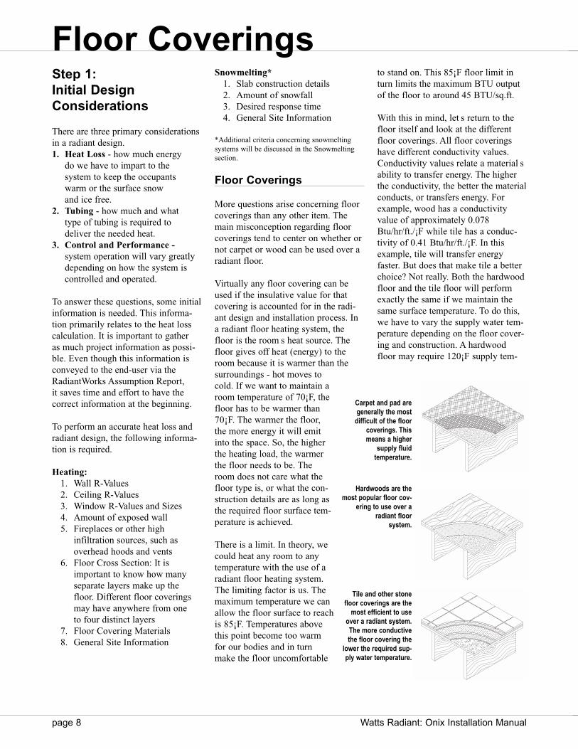
Virtually any floor covering can beused if the insulative value for thatcovering is accounted for in the radi-ant design and installation process. Ina radiant floor heating system, thefloor is the room s heat source. Thefloor gives off heat (energy) to theroom because it is warmer than thesurroundings - hot moves tocold. If we want to maintain aroom temperature of 70¡F, thefloor has to be warmer than70¡F. The warmer the floor,the more energy it will emitinto the space. So, the higherthe heating load, the warmerthe floor needs to be. Theroom does not care what thefloor type is, or what the con-struction details are as long asthe required floor surface tem-perature is achieved.
There is a limit. In theory, wecould heat any room to anytemperature with the use of aradiant floor heating system.The limiting factor is us. Themaximum temperature we canallow the floor surface to reachis 85¡F. Temperatures abovethis point become too warmfor our bodies and in turnmake the floor uncomfortable
to stand on. This 85¡F floor limit inturn limits the maximum BTU outputof the floor to around 45 BTU/sq.ft.
With this in mind, let s return to thefloor itself and look at the differentfloor coverings. All floor coveringshave different conductivity values.Conductivity values relate a material sability to transfer energy. The higherthe conductivity, the better the materialconducts, or transfers energy. Forexample, wood has a conductivityvalue of approximately 0.078Btu/hr/ft./¡F while tile has a conduc-tivity of 0.41 Btu/hr/ft./¡F. In thisexample, tile will transfer energyfaster. But does that make tile a betterchoice? Not really. Both the hardwoodfloor and the tile floor will performexactly the same if we maintain thesame surface temperature. To do this,we have to vary the supply water tem-perature depending on the floor cover-ing and construction. A hardwoodfloor may require 120¡F supply tem-
Floor Coverings
Carpet and pad aregenerally the most
difficult of the floorcoverings. This means a higher
supply fluid temperature.
Hardwoods are themost popular floor cov-
ering to use over aradiant floor
system.
Tile and other stonefloor coverings are the
most efficient to useover a radiant system.The more conductivethe floor covering the
lower the required sup-ply water temperature.

Watts Radiant: Onix Installation Manual page 9
perature while a tile floor may onlyrequire 100¡F.
Even though the main goal is the samefor all floor types, there are some spe-cial considerations that need to bemaintained for each floor covering.The following should be used as aguide only. If more information isrequired, contact the flooring manufac-turer for more specific information rel-ative to the actual floor covering beingused.
Tile Floors
Tile, stone and other masonry floorsare unique in the sense they are bond-ed to the main floor construction. Inaddition, they are extremely hard andto some degree brittle. Hard surfacesrequire special care during the installa-tion process, whether or not a radiantsystem is being installed.
Some items to be aware of are:
1. Floor stability. Tile will crack if the floor has a deflection greaterthan 1/360th of the span. To mini-mize this deflection adequate joists,subfloor and a stiffening layer,such as a tile backer board or addi-tional plywood, may be installedover the subfloor.
2. Crack/Isolation Membrane. Floors move and adjust continuous-ly over time as the environmentchanges. Tile installed over a slab
or a frame floor is subject to crackpropagation as the slab belowdevelops minor cracks or as thesubfloor shifts. A cleavage mem-brane or a crack/isolation layer isrecommended to prevent cracksfrom moving upward through thetile.
3. Mortar and Adhesives. There are a wide range of mortarsand adhesives used with tile andstone. Most standard mortar andlatex modified thin-sets are ade-quate for tile and stone applicationsover radiant.
As with any cement or mortar floor-ing, DO NOT apply heat to the sys-tem until the flooring materials havehad time to cure. This usually takesanywhere from 14 to 28 days.
Hardwood Flooring
Watts Radiant customers have success-fully installed parquet, laminated andstrip wood flooring over radiant tubingfor decades. Most wood floor manu-factures limit the floor surface temper-ature to 85¡F. Since the radiant designuses the same surface temperaturelimit, hardwoods can be used in almostany room or application with a radiantfloor.
This is not to say certain precautionsshould not be followed. These installa-tion techniques are the same for a radi-ant floor heating system as they are fora conventional forced air system.
Wood Moisture Content
Wood is hydroscopic, meaning it actslike a sponge. If the wood is installedwet relative to its surroundings, it willgive off the excess moisture andshrink. If the wood is installed dry rel-ative to its surroundings, it will absorbmoisture and expand. We all haveexperienced this within our ownhomes. The back door seems to fittighter in the summer than it does inthe winter. This is because the humidi-ty levels are higher in the summer. The
wood absorbs this excess moisture andexpands. A wood floor will do thesame thing. This is the reason why a1/2" to 3/4" gap is placed around theperimeter of the room.
On average, wood can expand or con-tract within 7% of its original size. Fora single planking of wood, this canequate to as much as 1/8" in width. Tohelp minimize this effect, a few guide-lines have been developed to reducethe effects moisture can have on awood floor.
1. The wood must be kiln dried. Kiln dried wood ensures the core ofthe wood is at the same moisturecontent as the outer surface
2. Hardwood Moisture Content.Wood is naturally stable between7% and 10% moisture content.
3. Subfloor Moisture Content. Make sure the moisture content ofthe subfloor is no higher than 4%above the hardwood itself. If it is,then moisture can be driven fromthe subfloor to the hardwood, caus-ing its internal moisture levels tochange.
4. Concrete Moisture. Make sure the concrete slab below the hardwood has a vapor barrier toprevent absorption from groundmoisture.
5. Room Moisture. Try to keep the room s relativehumidity between 35% and 50%moisture.Typical tile/stone installation sequence over a
frame floor.
Plywood Subfloor
Thin set
Backerboard
Tile Thin setTile/Stone Covering
Typical hardwood installation sequence over aframe floor.
Plywood Subfloor
Felt Paper (tar free)
Hardwood/Laminate Floor Covering
Floor Coverings

page 10 Watts Radiant: Onix Installation Manual
6. Use Strips, not Planks. The narrower the board, the less movement it will create. The idealsize is 3" to 3-1/2" in width.
7. Quarter Sawn vs. Plane Sawn.Quarter sawn wood will expand inheight while plane sawn wood willexpand in width. A quarter sawnboard is more dimensionally stablethan a plane sawn board.
Controlling Moisture
Hardwood floors are installed over aconcrete slab or a wooden subfloor.The most common cause of moistureproblems in a new home is moisturetrapped within the structure duringconstruction. Problems sometimesarise from a continuing source ofexcess moisture - for example, fromthe basement, crawl space or slab.
For a slab on or below grade, a mini-mum 6 mil plastic vapor barrier shouldbe used under the slab to prevent theabsorption of ground moisture throughthe concrete during the non-heatingseason. Verify with local code andbuilding practices.
Before wood flooring is installed overany slab or elevated thin slab, the slabshould be well aged. Preferably, theslab should have been heated for atleast a week before the flooring isdelivered. Pre-heating the slab beforeflooring installation will drive outresidual moisture that might causeproblems. This pre-heating must bedone before a surface vapor barrier isinstalled.
There is a simple procedure for check-ing the presence of excessive moisturein the slab. Tape a 4 ft. x 4 ft. sectionof polyethylene plastic sheeting to thesurface of the slab and turn on theheat. If moisture appears under theplastic, the slab should be heated foranother day or so and then checkedagain for moisture. If a hardwood flooris to be laid over a wooden subfloor,
similar precautions should beobserved, as the plywood subfloormay also be saturated with moisture.
The recommended procedure is to firstdrive off the moisture in the slab, thenheat the plywood subfloor for a fewdays before unwrapping the finishflooring from its factory packaging.
Plywood or oriented strand boardmake good candidates for subfloormaterials in radiant installations. Donot use particleboard as a subfloor.
USDA Forest Service
The following procedures are recom-mended by the USDA Forest ServicesWood Handbook .Cracks develop in flooring if (the
wood) absorbs moisture either before
or after it is laid, and then shrinkswhen the building is heated. Suchcracks can be greatly reduced byobserving the following practices:
1. Specify flooring manufactured according to association rules and sold by dealers that protect it properly during storage and delivery.
2. Do not allow the flooring to be delivered before the masonry andplastering are completed and fullydry, unless a dry storage space isavailable.
3. Have the heating plant installed before the flooring is delivered.
4. Break open the flooring bundles and expose all sides of the flooringto the atmosphere inside the struc-ture.
5. Close up the house at night andraise the temperature about 15¡Fabove the outdoor temperature for3 days before laying the floor.
6. If the house is not occupied imme-diately after the floor is laid, keepthe house closed at night or duringdamp weather and supply someheat, if necessary, to keep thehouse at about 65¡F.
Standard slab on grade construction
Without a vapor barrier: moisturemoves through a slab via capillarymovement.
With a vapor barrier, moistureis prevented from entering theslab.
% Moisture Approx. WidthChange Change/Inch
1 1/128"4 1/32"8 1/16"
12 5/64"16 7/64"20 9/64"24 11/64"
Potential Shrinkage
Installed Dimension
Potential Expansion
Hardwood expansion.
Floor Coverings
Watts Radiant: Onix Installation Manual page 11
Cautions for HardwoodFloor Installations:
If the radiant heating system cannot beinstalled prior to the hardwood instal-lation, an alternative form of heatneeds to be provided while the floor isbeing installed. Temporary, unventedsources of heat (such as a propanefired salamanders ) are not appropri-ate as they can put excessive amountsof water vapor into the building.
Asphalt paper should never be usedwhen installing a radiant floor heatingsystem, as some types of paper maygive off an unpleasant odor when theyare heated. If in doubt as to the pres-ence of old asphalt paper when doinga building renovation, a floor coresample needs to be taken. WattsRadiant does not recommend the useof underfloor radiant installationsunder asphalt paper.
As a rule of thumb, standard 3/4"hardwood floor coverings with a 3/4"subfloor does not pose a problem tonormal heat transfer. The efficiency ofa radiant floor begins to be affectedwhen the total thickness of wood cov-ering is between 2"—3". This range isdependent on the heating intensity.Lower heating intensities allow forthicker wood coverings.
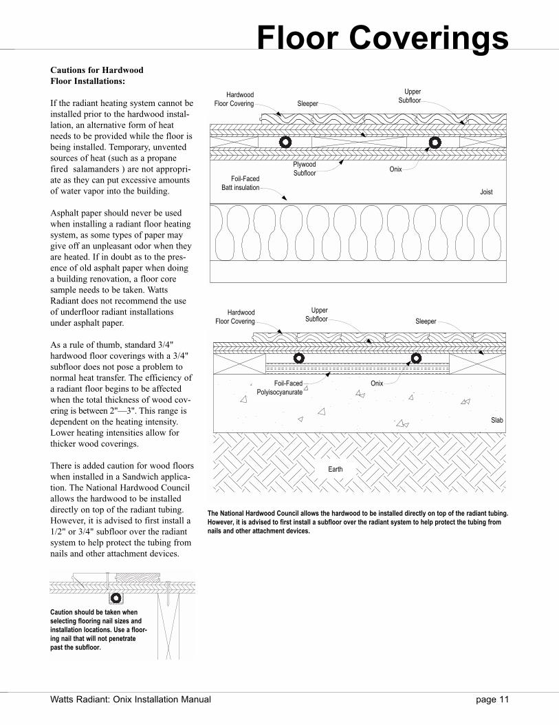
There is added caution for wood floorswhen installed in a Sandwich applica-tion. The National Hardwood Councilallows the hardwood to be installeddirectly on top of the radiant tubing.However, it is advised to first install a1/2" or 3/4" subfloor over the radiantsystem to help protect the tubing fromnails and other attachment devices.
Caution should be taken whenselecting flooring nail sizes andinstallation locations. Use a floor-ing nail that will not penetratepast the subfloor.
The National Hardwood Council allows the hardwood to be installed directly on top of the radiant tubing.However, it is advised to first install a subfloor over the radiant system to help protect the tubing fromnails and other attachment devices.
PlywoodSubfloor
Foil-FacedBatt insulation
Onix
Sleeper
UpperSubfloor
Joist
HardwoodFloor Covering
Sleeper
UpperSubfloor
HardwoodFloor Covering
Foil-FacedPolyisocyanurate
Onix
Slab
Earth
Floor Coverings
page 12 Watts Radiant: Onix Installation Manual
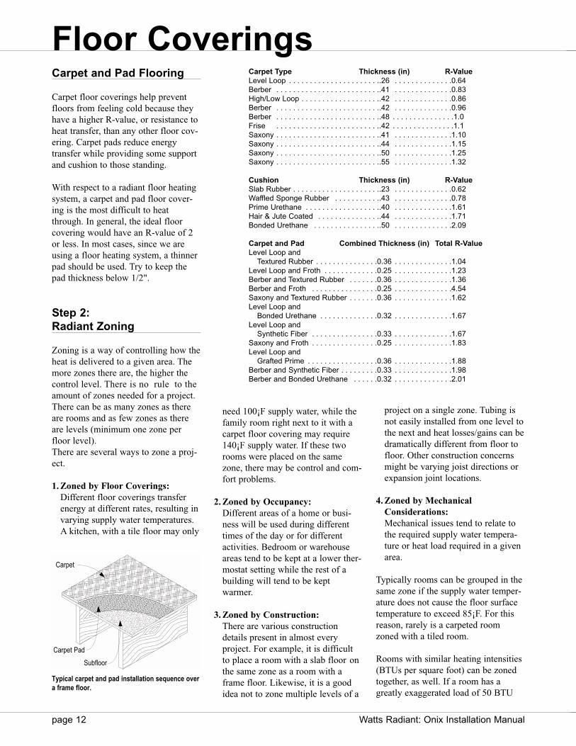
Carpet and Pad Flooring
Carpet floor coverings help preventfloors from feeling cold because theyhave a higher R-value, or resistance toheat transfer, than any other floor cov-ering. Carpet pads reduce energytransfer while providing some supportand cushion to those standing.
With respect to a radiant floor heatingsystem, a carpet and pad floor cover-ing is the most difficult to heatthrough. In general, the ideal floorcovering would have an R-value of 2or less. In most cases, since we areusing a floor heating system, a thinnerpad should be used. Try to keep thepad thickness below 1/2".
Step 2: Radiant Zoning
Zoning is a way of controlling how theheat is delivered to a given area. Themore zones there are, the higher thecontrol level. There is no rule to theamount of zones needed for a project.There can be as many zones as thereare rooms and as few zones as thereare levels (minimum one zone perfloor level).There are several ways to zone a proj-ect.
1. Zoned by Floor Coverings:Different floor coverings transferenergy at different rates, resulting invarying supply water temperatures.A kitchen, with a tile floor may only
need 100¡F supply water, while thefamily room right next to it with acarpet floor covering may require140¡F supply water. If these tworooms were placed on the samezone, there may be control and com-fort problems.
2. Zoned by Occupancy: Different areas of a home or busi-ness will be used during differenttimes of the day or for differentactivities. Bedroom or warehouseareas tend to be kept at a lower ther-mostat setting while the rest of abuilding will tend to be keptwarmer.
3. Zoned by Construction: There are various construction details present in almost every project. For example, it is difficult to place a room with a slab floor onthe same zone as a room with aframe floor. Likewise, it is a goodidea not to zone multiple levels of a
project on a single zone. Tubing isnot easily installed from one level tothe next and heat losses/gains can bedramatically different from floor tofloor. Other construction concernsmight be varying joist directions orexpansion joint locations.
4. Zoned by MechanicalConsiderations: Mechanical issues tend to relate tothe required supply water tempera-ture or heat load required in a givenarea.
Typically rooms can be grouped in thesame zone if the supply water temper-ature does not cause the floor surfacetemperature to exceed 85¡F. For thisreason, rarely is a carpeted roomzoned with a tiled room.
Rooms with similar heating intensities(BTUs per square foot) can be zonedtogether, as well. If a room has agreatly exaggerated load of 50 BTU
Carpet Type Thickness (in) R-ValueLevel Loop . . . . . . . . . . . . . . . . . . . . . ..26 . . . . . . . . . . . . . .0.64Berber . . . . . . . . . . . . . . . . . . . . . . . . ..41 . . . . . . . . . . . . . .0.83High/Low Loop . . . . . . . . . . . . . . . . . . ..42 . . . . . . . . . . . . . .0.86Berber . . . . . . . . . . . . . . . . . . . . . . . . ..42 . . . . . . . . . . . . . .0.96Berber . . . . . . . . . . . . . . . . . . . . . . . . ..48 . . . . . . . . . . . . . . .1.0Frise . . . . . . . . . . . . . . . . . . . . . . . . ..42 . . . . . . . . . . . . . . .1.1Saxony . . . . . . . . . . . . . . . . . . . . . . . . ..41 . . . . . . . . . . . . . .1.10Saxony . . . . . . . . . . . . . . . . . . . . . . . . ..44 . . . . . . . . . . . . . .1.15Saxony . . . . . . . . . . . . . . . . . . . . . . . . ..50 . . . . . . . . . . . . . .1.25Saxony . . . . . . . . . . . . . . . . . . . . . . . . ..55 . . . . . . . . . . . . . .1.32
Cushion Thickness (in) R-ValueSlab Rubber . . . . . . . . . . . . . . . . . . . . ..23 . . . . . . . . . . . . . .0.62Waffled Sponge Rubber . . . . . . . . . . ..43 . . . . . . . . . . . . . .0.78Prime Urethane . . . . . . . . . . . . . . . . . ..40 . . . . . . . . . . . . . .1.61Hair & Jute Coated . . . . . . . . . . . . . . ..44 . . . . . . . . . . . . . .1.71Bonded Urethane . . . . . . . . . . . . . . . ..50 . . . . . . . . . . . . . .2.09
Carpet and Pad Combined Thickness (in) Total R-ValueLevel Loop and
Textured Rubber . . . . . . . . . . . . . . .0.36 . . . . . . . . . . . . . .1.04Level Loop and Froth . . . . . . . . . . . . .0.25 . . . . . . . . . . . . . .1.23Berber and Textured Rubber . . . . . . .0.36 . . . . . . . . . . . . . .1.36Berber and Froth . . . . . . . . . . . . . . . .0.25 . . . . . . . . . . . . . .4.54Saxony and Textured Rubber . . . . . . .0.36 . . . . . . . . . . . . . .1.62Level Loop and
Bonded Urethane . . . . . . . . . . . . . .0.32 . . . . . . . . . . . . . .1.67Level Loop and
Synthetic Fiber . . . . . . . . . . . . . . . .0.33 . . . . . . . . . . . . . .1.67Saxony and Froth . . . . . . . . . . . . . . . .0.25 . . . . . . . . . . . . . .1.83Level Loop and
Grafted Prime . . . . . . . . . . . . . . . . .0.36 . . . . . . . . . . . . . .1.88Berber and Synthetic Fiber . . . . . . . . .0.33 . . . . . . . . . . . . . .1.98Berber and Bonded Urethane . . . . . .0.32 . . . . . . . . . . . . . .2.01
Subfloor
Carpet Pad
Carpet
Typical carpet and pad installation sequence overa frame floor.
Floor Coverings
Watts Radiant: Onix Installation Manual page 13
per square foot, like a Sunroom, itshould not be zoned with a room thatonly requires 10 BTUs per square foot.
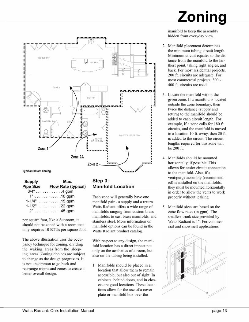
The above illustration uses the occu-pancy technique for zoning, dividingthe waking areas from the sleep-ing areas. Zoning choices are subjectto change as the design progresses. Itis not uncommon to go back andrearrange rooms and zones to create abetter overall design.
Step 3: Manifold Location
Each zone will generally have onemanifold pair - a supply and a return.Watts Radiant offers a wide range ofmanifolds ranging from custom brassmanifolds, to cast brass manifolds, andstainless steel. More information onmanifold options can be found in theWatts Radiant product catalog.
With respect to any design, the mani-fold location has a direct impact notonly on the aesthetics of a room, butalso on the tubing being installed.
1. Manifolds should be placed in alocation that allow them to remainaccessible, but also out of sight. Incabinets, behind doors, and in clos-ets are good locations. These loca-tions allow for the use of a coverplate or manifold box over the
manifold to keep the assembly hidden from everyday view.
2. Manifold placement determines the minimum tubing circuit length.Minimum circuit equates to the dis-tance from the manifold to the far-thest point, taking right angles, andback. For most residential projects,200 ft. circuits are adequate. Formost commercial projects, 300 -400 ft. circuits are used.
3. Locate the manifold within the given zone. If a manifold is locatedoutside the zone boundary, thentwice the distance (supply andreturn) to the manifold should be added to each circuit length. Forexample, if a zone calls for 180 ft.circuits, and the manifold is movedto a location 10 ft. away, then 20 ft.is added to the circuit. The circuitlengths required for this zone willbe 200 ft.
4. Manifolds should be mounted horizontally, if possible. Thisallows for easier circuit connectionto the manifold. Also, if avent/purge assembly (recommend-ed) is installed on the manifolds,they must be mounted horizontallyin order to allow the vents to work properly without leaking.
5. Manifold sizes are based on the zone flow rates (in gpm). The smallest trunk size provided by Watts Radiant is 1". For commer-cial and snowmelt applications
Supply Max.Pipe Size Flow Rate (typical)
3/4" . . . . . . . . . . . .4 gpm1" . . . . . . . . . . . .10 gpm
1-1/4" . . . . . . . . . .15 gpm1-1/2" . . . . . . . . . .22 gpm
2" . . . . . . . . . . . .45 gpm
ZONE 1
ZONE 2A
ZONE 2
Typical radiant zoning.
Zoning

page 14 Watts Radiant: Onix Installation Manual
larger manifolds, 1-1/4" to 6" i.d.,are available.
Step 4: Heat Loss Calculation
Conventional heat loss calculationscan be used to size radiant heatingequipment; however they tend to over-state the actual heat loss that a radiant-ly heated building experiences. In
addition, the use of these unadjustedcalculations will tend to oversize boil-ers, circulators, and piping, as well asthe amount of radiant piping required.There are four major factors thatreduce heat loads as compared to con-ventional heating systems.
1. Lower indoor air temperatures can be maintained for greater human comfort. When the floor isradiantly warmed, the human bodydoes not need as warm an air tem-
perature to stay comfortable. Withradiant heat, the indoor thermostatcan be set 2¡—3¡ lower.
2. Indoor air movement and tempera-ture gradient is greatly reduced. This reduces heat loss through the ceiling.
3. Due to heat storage in the radiantfloor and surrounding walls, peakheating loads are reduced. Thiseffect is greater in more massiveconstruction.
4. Because of factors one and two,infiltration losses are also less. Thismeans buildings with higher airinfiltration rates will save moreenergy if fitted with a radiant floordelivery system, compared to aforced air (convective) heating system.
Due to these factors, a typical radiantheated building often requires 10% to 30% less energy to heat than aconventional convective system.RadiantWorks automatically accountsfor these factors to properly and accurately size any radiant project.
Using RadiantWorks®
Reports as a Design Tool
For most projects, the radiant designwill be performed using WattsRadiant s RadiantWorks design soft-ware. This is an easy, efficient way toapply the design steps discussed earli-er. A variety of reports are availablethrough RadiantWorks, including aZone List, an Assumption report and aHeat Loss report. These reports help totransfer information about a givenproject quickly without unnecessaryguess work.
Supply Line
Return Line
Onix
Manifold
Manifold mounted on side of joist.Use fasteners, as necessary, to support Onix and to maintain proper bend radii.
Manifold
Onix
SnapClip Fasteners
Manifold mounted in wall cavity.Use fasteners, as necessary, to support Onix and to maintain proper bend radii.
Manifold Mounting Bracket
Max Flow Base TrunkGPM Size
12 1"20 1-1/4"32 1-1/2"60 2"
SnapClip Fasteners
Zoning
Watts Radiant: Onix Installation Manual page 15
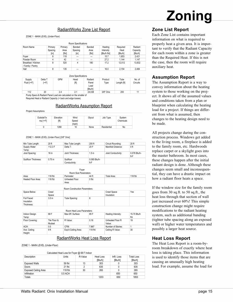
Zone List ReportEach Zone List contains importantinformation on what is required toproperly heat a given area. It is impor-tant to verify that the Radiant Capacityfor each room within a zone is greaterthan the Required Heat. If this is notthe case, then the room will requireauxiliary heat.
Assumption Report The Assumption Report is a way toconvey information about the heatingsystem to those working on the proj-ect. It shows all of the assumed valuesand conditions taken from a plan orblueprint when calculating the heatingload for a project. If things are differ-ent from what is assumed, thenchanges to the heating design need tobe made.
All projects change during the con-struction process. Windows get addedto the living room, a fireplace is addedto the family room, etc. Hardwoodsreplace carpet or a skylight goes intothe master bathroom. In most cases,these changes happen after the initialradiant design is done. Although thesechanges seem small and inconsequen-tial, they can have a drastic impact onhow a radiant floor heats a space.
If the window size for the family roomgoes from 30 sq.ft. to 50 sq.ft., theheat loss through that section of walljust increased over 60%! This simpleconstruction change might requiremodifications to the radiant heatingsystem, such as additional banding(tighter tube spacing along an exposedwall) or higher water temperatures andpossibly a larger heat source.
Heat Loss ReportThe Heat Loss Report is a room-by-room breakdown of exactly where heatloss is taking place. This informationis used to identify those items that arecausing an unusually high heatingload. For example, assume the load for
ZONE 1 - MAIN LEVEL (Under-Floor)
Room SpecificationsRoom Name Primary
Spacing[in]
PrimaryArea[ft≤]
BandedSpacing
[in]
BandedArea[ft≤]
HeatingIntensity[Btu/h ft≤]
RequiredHeat
[Btu/h]
RadiantCapacity
[Btu/h]Foyer 8 118 --- --- 15.7 1,853 2,421Powder Room 4 42 --- --- 27.2 1,144 1,147Breakfast / Kitchen / Family / Pantry
8 520 4 180 17.2 12,012 13,832
Hall 8 135 --- --- 16.0 2,154 2,484
Zone SpecificationsSupply
Fluid [∞F]Delta T
[∞F]GPM Head
[ft]Radiant
PanelLoad
[Btu/h]
ProductType
TubeLength [ft]
No. ofCircuits
112 20 2.4 2.1 24,038 3/8" Onix 200 11Pump Specs & Radiant Panel Load are calculated on the smaller ofRequired Heat or Radiant Capacity (+ back and edge losses)
Project Assumptions
OutsideTemp [∞F]
Elevation[ft]
WindSpeed[mph]
Glycol Job Type SystemChemicals
0 1268 10 None Residential No
ZONE 1 - MAIN LEVEL (Under-Floor) [3/8" Onix]
Min Tube Length: 20 ft Max Tube Length: 200 ft Circuit Rounding: 20 ftSupply Water Temp:
112.3 F Delta T: 20 F Manifold Distance: 0 ft
Joist Spacing: 16 in Joint Thickness: 1.5 in Joist Conductivity: 0.078 Btu/h-ft-F
Subfloor Thickness: 0.75 in Subfloor Conductivity:
0.085 Btu/h-ft-F
FoyerRoom Size Parameters:
Area: 118 ft≤ Perimeter: 44 ft Total Area: 118 ft≤Heated Floor Area: 118 ft≤ Unheated Floor
Area:0 ft≤
Room Construction Parameters:Space Below: Crawl
SpaceCrawl Space Insulation:
Yes
Foil Faced Insulation Thickness:
3.5 in Tube Spacing: 8
Room Heat Loss Parameters:Indoor Design Temp:
68 F Max Eff. Surface: 85 F Heating Intensity: 15.70 Btu/h ft≤
Floor Covering: Tile Floor & Mudset
R Value: 0.16 Unheated Floor R Value:
19
ACH: 0.5 CFM: 7.867 Number of Stories: 1Ave. Ceiling Height:
9 ft Exp'd Ceiling Area: 118 ft≤ Ceiling R Value: 30
ZONE 1 - MAIN LEVEL (Under-Floor)
Calculated Heat Loss for Foyer @ 68 F IndoorDescription Units R-Value Heat Loss
[Btu/h]Infil. Loss
[Btu/h]Total Loss
[Btu/h]Exposed Walls 59 ft≤ 13 303 0 303Doors 21 ft≤ 2 635 0 635Exposed Ceiling Area 118 ft≤ 30 265 0 265Infiltration 0.5 ACH 650 650Totals 1203 650 1853
ZoningRadiantWorks Zone List Report
RadiantWorks Assumption Report
RadiantWorks Heat Loss Report
page 16 Watts Radiant: Onix Installation Manual
a room were 10,000 BTUs and thewindows were single pane and had atotal heat loss of 6700 BTUs. TheHeat Loss Report would reflect thisunusually high heat loss area and adecision to install double pane win-dows might be made to help make thisroom more energy efficient.
Applications
As construction materials improve,installation details change. It would beimpossible to try to fit all possibleconstruction scenarios into this manu-al. Because of this, only the most com-mon applications are discussed. Eachcontains examples and techniques forthe most popular variations.
Should a project call for a constructiondetail not mentioned in this manual,please feel free to contact WattsRadiant for design assistance.
Frame Floors
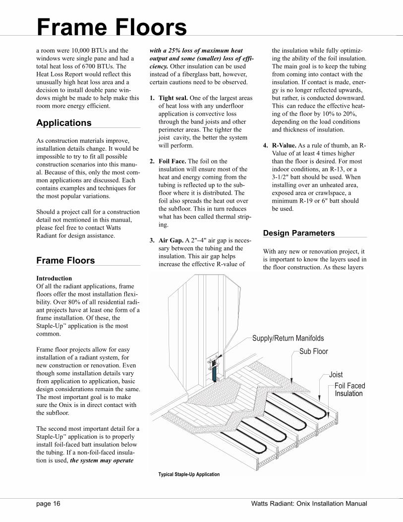
Introduction Of all the radiant applications, framefloors offer the most installation flexi-bility. Over 80% of all residential radi-ant projects have at least one form of aframe installation. Of these, theStaple-Up™ application is the mostcommon.
Frame floor projects allow for easyinstallation of a radiant system, fornew construction or renovation. Eventhough some installation details varyfrom application to application, basicdesign considerations remain the same.The most important goal is to makesure the Onix is in direct contact withthe subfloor.
The second most important detail for aStaple-Up™ application is to properlyinstall foil-faced batt insulation belowthe tubing. If a non-foil-faced insula-tion is used, the system may operate
with a 25% loss of maximum heatoutput and some (smaller) loss of effi-ciency. Other insulation can be usedinstead of a fiberglass batt, however,certain cautions need to be observed.
1. Tight seal. One of the largest areasof heat loss with any underfloorapplication is convective lossthrough the band joists and otherperimeter areas. The tighter thejoist cavity, the better the systemwill perform.
2. Foil Face. The foil on the insulation will ensure most of theheat and energy coming from thetubing is reflected up to the sub-floor where it is distributed. Thefoil also spreads the heat out overthe subfloor. This in turn reduceswhat has been called thermal strip-ing.
3. Air Gap. A 2"–4" air gap is neces-sary between the tubing and theinsulation. This air gap helpsincrease the effective R-value of
the insulation while fully optimiz-ing the ability of the foil insulation.The main goal is to keep the tubingfrom coming into contact with theinsulation. If contact is made, ener-gy is no longer reflected upwards,but rather, is conducted downward.This can reduce the effective heat-ing of the floor by 10% to 20%,depending on the load conditionsand thickness of insulation.
4. R-Value. As a rule of thumb, an R-Value of at least 4 times higherthan the floor is desired. For mostindoor conditions, an R-13, or a 3-1/2" batt should be used. Wheninstalling over an unheated area,exposed area or crawlspace, a minimum R-19 or 6" batt should be used.
Design Parameters
With any new or renovation project, itis important to know the layers used inthe floor construction. As these layers
Frame Floors
Foil Faced Joist
Sub Floor
Supply/Return Manifolds
Typical Staple-Up Application
Insulation
Watts Radiant: Onix Installation Manual page 17
increase or change, variances in theheating system will result.
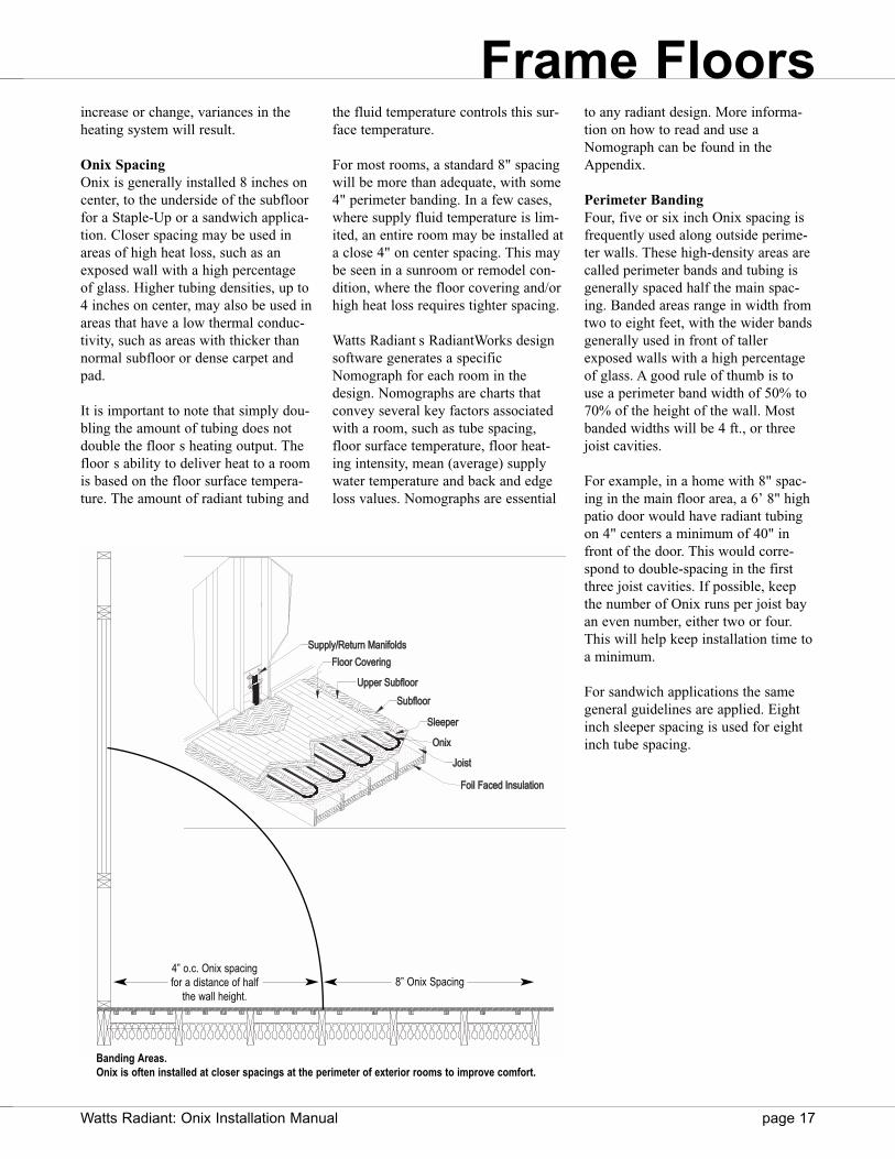
Onix SpacingOnix is generally installed 8 inches oncenter, to the underside of the subfloorfor a Staple-Up or a sandwich applica-tion. Closer spacing may be used inareas of high heat loss, such as anexposed wall with a high percentageof glass. Higher tubing densities, up to4 inches on center, may also be used inareas that have a low thermal conduc-tivity, such as areas with thicker thannormal subfloor or dense carpet andpad.
It is important to note that simply dou-bling the amount of tubing does notdouble the floor s heating output. Thefloor s ability to deliver heat to a roomis based on the floor surface tempera-ture. The amount of radiant tubing and
the fluid temperature controls this sur-face temperature.
For most rooms, a standard 8" spacingwill be more than adequate, with some4" perimeter banding. In a few cases,where supply fluid temperature is lim-ited, an entire room may be installed ata close 4" on center spacing. This maybe seen in a sunroom or remodel con-dition, where the floor covering and/orhigh heat loss requires tighter spacing.
Watts Radiant s RadiantWorks designsoftware generates a specificNomograph for each room in thedesign. Nomographs are charts thatconvey several key factors associatedwith a room, such as tube spacing,floor surface temperature, floor heat-ing intensity, mean (average) supplywater temperature and back and edgeloss values. Nomographs are essential
SupSupplyply/Return Mananifololdsds
Flooror CovCovereringng
UppUpperer SubSubfloorloor
SubSubfloorloor
Oninix
Joisoist
Foiloil FaFaced d Insulationon
SlSleepeperer
to any radiant design. More informa-tion on how to read and use aNomograph can be found in theAppendix.
Perimeter BandingFour, five or six inch Onix spacing isfrequently used along outside perime-ter walls. These high-density areas arecalled perimeter bands and tubing isgenerally spaced half the main spac-ing. Banded areas range in width fromtwo to eight feet, with the wider bandsgenerally used in front of tallerexposed walls with a high percentageof glass. A good rule of thumb is touse a perimeter band width of 50% to70% of the height of the wall. Mostbanded widths will be 4 ft., or threejoist cavities.
For example, in a home with 8" spac-ing in the main floor area, a 6’ 8" highpatio door would have radiant tubingon 4" centers a minimum of 40" infront of the door. This would corre-spond to double-spacing in the firstthree joist cavities. If possible, keepthe number of Onix runs per joist bayan even number, either two or four.This will help keep installation time toa minimum.
For sandwich applications the samegeneral guidelines are applied. Eightinch sleeper spacing is used for eightinch tube spacing.
4” o.c. Onix spacingfor a distance of half
the wall height.8” Onix Spacing
Banding Areas.Onix is often installed at closer spacings at the perimeter of exterior rooms to improve comfort.
Frame Floors
page 18 Watts Radiant: Onix Installation Manual
Staple Up™ Application
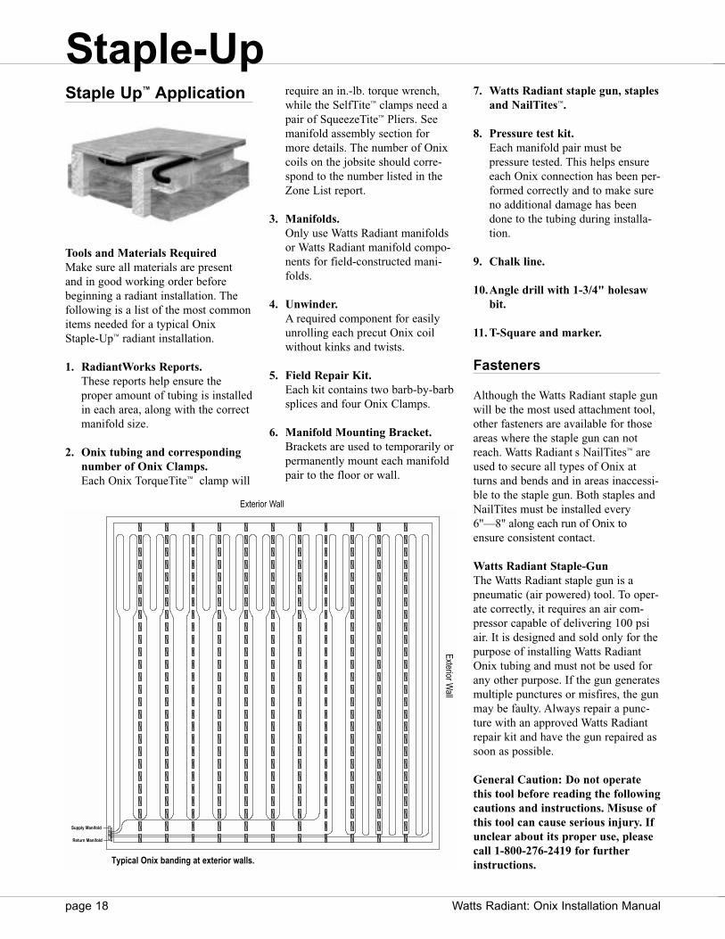
Tools and Materials RequiredMake sure all materials are presentand in good working order beforebeginning a radiant installation. Thefollowing is a list of the most commonitems needed for a typical OnixStaple-Up™ radiant installation.
1. RadiantWorks Reports. These reports help ensure the proper amount of tubing is installedin each area, along with the correctmanifold size.
2. Onix tubing and correspondingnumber of Onix Clamps. Each Onix TorqueTite™ clamp will
require an in.-lb. torque wrench,while the SelfTite™ clamps need apair of SqueezeTite™ Pliers. Seemanifold assembly section formore details. The number of Onixcoils on the jobsite should corre-spond to the number listed in theZone List report.
3. Manifolds.Only use Watts Radiant manifoldsor Watts Radiant manifold compo-nents for field-constructed mani-folds.
4. Unwinder.A required component for easily unrolling each precut Onix coil without kinks and twists.
5. Field Repair Kit. Each kit contains two barb-by-barbsplices and four Onix Clamps.
6. Manifold Mounting Bracket.Brackets are used to temporarily orpermanently mount each manifoldpair to the floor or wall.
7. Watts Radiant staple gun, staplesand NailTites™.
8. Pressure test kit.Each manifold pair must be pressure tested. This helps ensureeach Onix connection has been per-formed correctly and to make sureno additional damage has beendone to the tubing during installa-tion.
9. Chalk line.
10.Angle drill with 1-3/4" holesaw bit.
11. T-Square and marker.
Fasteners
Although the Watts Radiant staple gunwill be the most used attachment tool,other fasteners are available for thoseareas where the staple gun can notreach. Watts Radiant s NailTites™ areused to secure all types of Onix atturns and bends and in areas inaccessi-ble to the staple gun. Both staples andNailTites must be installed every6"—8" along each run of Onix toensure consistent contact.
Watts Radiant Staple-GunThe Watts Radiant staple gun is apneumatic (air powered) tool. To oper-ate correctly, it requires an air com-pressor capable of delivering 100 psiair. It is designed and sold only for thepurpose of installing Watts RadiantOnix tubing and must not be used forany other purpose. If the gun generatesmultiple punctures or misfires, the gunmay be faulty. Always repair a punc-ture with an approved Watts Radiantrepair kit and have the gun repaired assoon as possible.
General Caution: Do not operatethis tool before reading the followingcautions and instructions. Misuse ofthis tool can cause serious injury. Ifunclear about its proper use, pleasecall 1-800-276-2419 for furtherinstructions.
Supplyly Manifold
Return Manifold
Exterior Wall
Exterior Wall
Typical Onix banding at exterior walls.
Staple-Up
Supply Manifold
Return Manifold

Watts Radiant: Onix Installation Manual page 19
1. This tool may discharge when airpressure is connected or discon-nected. Make sure the tool isunloaded or pointed in a safe direc-tion before connecting/disconnect-ing a pressure hose.
2. Remember, any pneumatic staplegun is exactly that, a gun. Each sta-ple gun has the ability to shoot sta-ples at a velocity sufficient to killor permanently injure anyone within range. Never point this toolat anything except a piece of Onixintending to be permanently fas-tened. Never squeeze the triggerwhen your finger, hand or anybody part is in front of or close tothe firing head.
3. Always wear safety glasses withside shields before operating thistool. Other workmen or visitors tothe jobsite must wear adequate eye protection if they are within rangeof the tool. There is always a possi-bility that a staple could ricochetoff a nail or knot in the subfloorand injure a bystander. DO NOTattempt to staple into knots, even ifthe staple spacing needs to be extended. Never attempt to stapleinto concrete, metal, or any non-wooden surface.
4. Use the correct staple gun and quality Watts Radiant staples to prevent tool jamming and Onix punctures. Watts Radiant staplesare designed to a higher standardthan conventional staples.Occasionally a staple will misfireand puncture the Onix when thestaple clip is down to the last 5 to
10 staples. Always check to see ifthe clip is getting low and insert anew clip to avoid this potential problem.
Using the Onix Staple GunThe Onix staple gun is specially modi-fied both internally and externally byWatts Radiant. The Onix staple gun isfitted with a stainless steel guide plate(order 81005498) that is bolted to theunderside of the gun. If stapling 3/8"Onix, make sure the smaller 3/8"opening is at the front of the gun. Youshould see 3/8" Onix stamped on theguide plate at the front of the gun. Ifstapling 1/2" Onix, unbolt the guideplate and turn it around so the larger1/2" opening is at the front of the staple gun. You should see 1/2"Onix stamped on the guide plate atthe front of the gun.
To staple Onix, position the guideplate over the Onix. Make sure theguide plate, at both front and back, isplaced firmly against the surface.Before pulling the trigger, make surethat the tail end of the guide plate isalso centered over the Onix. If the tailof the guide plate is not centered overthe tubing, some of the staples maypuncture the Onix. When the guideplate has completely contacted the plywood and is centered over the Onix tubing, pull the trigger and firethe staple.
To maintain good operation of the gun, 3 to 4 drops of pneumatic oil (5-weight, non-detergent machine oil)should be installed once daily duringuse into the air inlet of the staple gun.More oil drops may be used if the gunsees continuous heavy service, i.e.,more than 3–4 hours at a time.
Onix Cautions
1. Examine each Onix circuit after ithas been stapled in place. If theOnix has been over-compressed bya staple, remove the staple andapply a new one. The staple can acceptably deform the Onix slight-ly, 1/16" or less, without causingany difficulties.
2. Do not install Onix, or any otherradiant system under floors con-taining an asphalt paper slip jointbetween the subfloor and finishedfloor, as an unpleasant smell mayresult.
Installation Steps
Installation procedures will changefrom job to job and are affected byhow the structure is built. Joist spac-ing, bracing and zoning details are justa few items that can affect how aStaple-Up™ is installed. The followingguidelines and examples cover themost common installation conditions.If unexpected circumstances arise,please contact Watts Radiant or aWatts Radiant Representative for assis-tance.
The most common installation patternused in a Staple-Up™ application is asingle serpentine layout. Other layoutmethods, such as counter flow, can beused, depending on the project require-ments.
Step 1: Install ManifoldsWith the use of Watts Radiant s mani-fold brackets or manifold mountingenclosure, secure the manifolds to thejoist or wall enclosure. If the mani-folds are located in the wall above theradiant floor, drill holes to transferOnix through the subfloor and into thejoist cavity below. If the manifolds arelocated in the joist bay, simply attachthe manifolds to the side of a joist orinstall a manifold enclosure horizon-tally to the joist. Follow local codeguidelines when penetrating any fram-ing members.
Good Staple Onix deformed too much.
Onix
Staple-Up
Onix Staple Plate
page 20 Watts Radiant: Onix Installation Manual
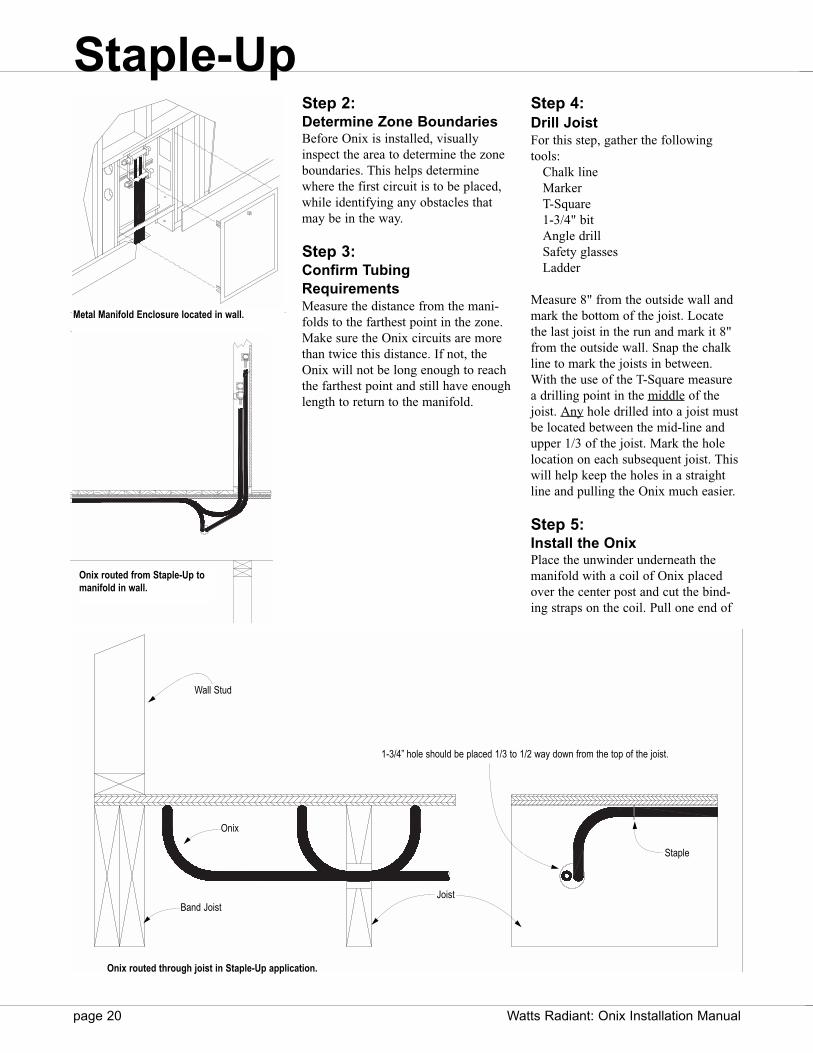
Step 2: Determine Zone BoundariesBefore Onix is installed, visuallyinspect the area to determine the zoneboundaries. This helps determinewhere the first circuit is to be placed,while identifying any obstacles thatmay be in the way.
Step 3: Confirm TubingRequirementsMeasure the distance from the mani-folds to the farthest point in the zone.Make sure the Onix circuits are morethan twice this distance. If not, theOnix will not be long enough to reachthe farthest point and still have enoughlength to return to the manifold.
Step 4: Drill JoistFor this step, gather the followingtools:
Chalk lineMarkerT-Square1-3/4" bitAngle drillSafety glassesLadder
Measure 8" from the outside wall andmark the bottom of the joist. Locatethe last joist in the run and mark it 8"from the outside wall. Snap the chalkline to mark the joists in between.With the use of the T-Square measurea drilling point in the middle of thejoist. Any hole drilled into a joist mustbe located between the mid-line andupper 1/3 of the joist. Mark the holelocation on each subsequent joist. Thiswill help keep the holes in a straightline and pulling the Onix much easier.
Step 5: Install the OnixPlace the unwinder underneath themanifold with a coil of Onix placedover the center post and cut the bind-ing straps on the coil. Pull one end of
Metal Manifold Enclosure located in wall.
Wall Stud
JoistBand Joist
1-3/4” hole should be placed 1/3 to 1/2 way down from the top of the joist.
Onix routed from Staple-Up tomanifold in wall.
Onix
Staple
Onix routed through joist in Staple-Up application.
Staple-Up

Watts Radiant: Onix Installation Manual page 21
the Onix off the unwinder and looselyattach it to the first barb of one of themanifolds. Take a white paint pen, orother marker, and mark this end ofOnix with a number 1, indicating thefirst circuit installed. Do the same tothe other end of Onix, marking it withthe number 1. This will help later inthe installation process.
Do not push the Onix on more thanthe first barb at this point, just in casethe circuit needs to be moved. Pull thefree end of the Onix from theunwinder and fold the circuit in themiddle to form a loop. Pull the loop(mid point of the circuit) through theseries of pre-drilled holes to the lastjoist bay. Continue to pull the loopdown the bay until the loop is 8" fromthe end.
When looking at the Onix in the firstbay, one side will be fixed . This sideis the side that is attached to the mani-fold. Staple this side of the tubingfirst, then staple the free side. Thiswill allow any excess tubing that mayhave been pulled to be pushed backover to the next bay. Make sure to staple the Onix every 6"—8" on center.Staples placed farther apart than 8"can cause the Onix to pull away fromthe subfloor, resulting in a reduction inheat transfer to the subfloor.
Continue, moving from bay to bayuntil all of the Onix is used. Stopwhen the free end of Onix that is stillon the unwinder slips off. Take thefree end and attach it to the returnmanifold.
It is always a good idea to connect thecircuits to the manifolds in reversereturn pattern, i.e. the first water in, is the last water out.
Step 6: Repeat With The Next CircuitRepeat steps 4 through 6, keeping thenew series of joist holes at least 8"away from the first to maintain struc-tural integrity of the joist. Pull theOnix down to the first open bay, gen-
Attach one end of the Onix to thesupply manifold.
Leave one end of the Onix on theunwinder and pull from this end.
Use a chalk line to align drill holes.
Loop the Onix and pull theloop through the drilledjoists.
Pull the Onix down the far joist bayand space the tubing according todesign.
Repeat until the Onix comes off theunwinder. Attach the free end to thereturn manifold.
Make sure to use all of the Onix tubingspecified for the zone. Do not cut cir-cuits to make them shorter as an imbal-ance in flow may occur
Staple-Up
Typical Onix Staple-Up.

page 22 Watts Radiant: Onix Installation Manual
erally next to the partially filled bayleft from the last circuit. At the end ofthis bay, drill one hole to allow accessinto the partially filled bay. Run theOnix to fill this partial bay and thenew bay. Continue as before, filling allsubsequent joist bays.
Make sure to use as much of each cir-cuit as possible. If the last circuit istoo long, try not to cut it shorter.Shorter circuits have a lower pressuredrop and will tend to cause an imbal-ance in the fluid flow. Some tubingmay be removed from this last circuitas long as the remaining length iswithin 10% of the existing circuits.For example, if 200 ft. lengths wereinstalled, the last circuit can be cut to alength of 180 ft. and still maintain abalanced system. If more than 10% isin excess, run the remaining tubingalong an exposed wall or in otherareas of the zone.
Step 7: Visual InspectionAfter all the circuits are installed, takea few minutes to walk each circuit andvisually inspect the tubing for possibledamage caused during installation. If adamaged area is found, repair it usingan approved Watts Radiant Repair Kit.More information on the repair kitscan be found in the Appendix.
Step 8: Final Assembly and Pressure TestWith the zone fully installed andinspected, finish the connections to themanifold. Begin by identifying corre-sponding ends to the same circuit. Ifthe tubing has not been marked, selecttwo circuit ends and blow through one,with a thumb placed over the otherend. Air should be felt on the otherside, confirming both ends of the samecircuit have been selected.
Take one Onix Clamp and slide it overone end of tubing. Slide the clampdown about 2" from the end and pushthe Onix onto the first barb of the sup-ply manifold, making sure the tubingcovers the entire fitting. If the Onix isdifficult to push onto the barb, lubri-cate the end of the Onix with somewater.
Do not use soap, oil, WD-40®, orother petroleum or silicone basedlubricants as they may damage theinterior of the Onix tubing. Soap orlubricants may make the connects andsplices leak, even at low pressures.
Slide the Onix Clamp back over theOnix and barb connection. If usingSureClamps, do not over-tighten theclamp. Tighten the Onix Clamp to 25-30 in-lbs. using Watts Radiant spreset torque driver. If a torque driveris not available, tighten the clamp tosnug and then one additional quarterturn. More information on how toinstall Onix Clamps can be found inthe Appendix.
Zone 1Main Living Area
Zone 2Main Sleeping Area
Typical Staple-Up application.
Manifold
Onix BarbOnix Clamp
Onix
Manifold
Pressure Test Kit
Staple-Up
WD-40 is a registered trademark of the WD-40 Company.
Watts Radiant: Onix Installation Manual page 23
Caution: DO NOT over tighten theclamps. Over tightening may causean improper fit.
For detailed information on the propersteps to conducting a pressure test,refer to the Appendix of the installa-tion manual.
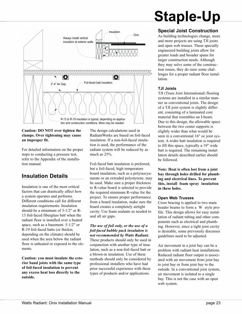
Insulation Details
Insulation is one of the most criticalfactors that can drastically affect howa system operates and performs.Different conditions call for differentinsulation requirements. Insulationshould be a minimum of 3-1/2" or R-13 foil-faced fiberglass batt when theradiant floor is installed over a heatedspace, such as a basement. 5-1/2" orR-19 foil-faced batts (or thicker,depending on the climate) should beused when the area below the radiantfloor is unheated or exposed to the ele-ments.
Caution: you must insulate the exte-rior band joists with the same typeof foil-faced insulation to preventany excess heat loss directly to theoutside.
The design calculations used inRadiantWorks are based on foil-facedinsulation. If a non-foil-faced insula-tion is used, the performance of theradiant system will be reduced by asmuch as 25%.
Foil-faced batt insulation is preferred,but a foil-faced, high temperatureboard insulation, such as a polyisocya-nurate or an extruded polystyrene, maybe used. Make sure a proper thicknessto R-value board is selected to providethe required minimum R-value for theproject. To ensure proper performancefrom a board insulation, make sure theboard creates a completely airtightcavity. Use foam sealants as needed toseal all air gaps.
The use of foil only, or the use of afoil-faced bubble pack insulation isnot recommended by Watts Radiant.These products should only be used inconjunction with another type of insu-lation, such as a non-foil-faced batt ora blown-in insulation. Use of thesemethods should only be considered byprofessional installers who have hadprior successful experience with thesetypes of products and/or applications.
Special Joist ConstructionAs building technologies change, moreand more projects are using TJI joistsand open web trusses. These speciallyengineered building joists allow forgreater loads and broader spans forlarger construction needs. Althoughthey may solve some of the construc-tion issues, they do raise some chal-lenges for a proper radiant floor instal-lation.
TJI JoistsTJI (Truss Joist International) flooringsystems are installed in a similar man-ner as conventional joists. The designof a TJI joist system is slightly differ-ent, consisting of a laminated corematerial that resembles an I-beam.Due to this design, the allowable spacebetween the two center supports isslightly wider than what would beseen in a conventional 16" oc joist sys-tem. A wider batt insulation is requiredto fill this space, typically a 19" widebatt is required. The remaining instal-lation details described earlier shouldbe followed.
Note: Heat is often lost from a joistbay through holes drilled for plumb-ing and electrical lines. To preventthis, install foam spray insulationin these holes.
Open Web TrussesCross bracing is applied to two mainheader beams to form a W style pro-file. This design allows for easy instal-lation of radiant tubing and other com-ponents such as electrical and plumb-ing. However, since a tight joist cavityis desirable, some previously discussesguidelines need to be adjusted.
Air movement in a joist bay can be aproblem with radiant heat installations.Reduced radiant floor output is associ-ated with air movement from joist bayto joist bay or from joist bay to theoutside. In a conventional joist system,air movement is isolated to a singlebay. This is not the case with an openweb system.
OnixInsulation
Always install verticalinsulation at exterior walls.
Foil-faced batt insulation
R-13 to R-19 insulation is typical, depending on applica-tion and construction conditions. More may be needed.
2”-4” Air Gap
Staple-Up
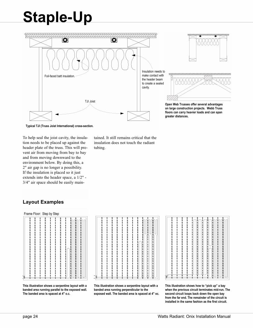
page 24 Watts Radiant: Onix Installation Manual
To help seal the joist cavity, the insula-tion needs to be placed up against theheader plate of the truss. This will pre-vent air from moving from bay to bayand from moving downward to theenvironment below. By doing this, a2" air gap is no longer a possibility. If the insulation is placed so it justextends into the header space, a 1/2" -3/4" air space should be easily main-
tained. It still remains critical that theinsulation does not touch the radianttubing.
The above illustration shows a serpentine layout with a banded area running parallel to the exposed wall. The banded area is spaced at 4" oc.
Return Manifold
Supply Manifold
Frameme F Floor: S: Stetep by Step
The above illustration shows a sperpentine layout with a banded area running perpendicular to the exposed wall. The banded area is spaced at 4" oc.
Supply Manifold
Return Manifold
The above illustration shows how to "pick up" a bay when the previous circuit terminates mid-run. The second circuit loops back down the open bay from the far end. The remainder of the circuit is installed in the same fashion as the first circuit.
Return Manifold
Supply Manifold
This illustration shows a serpentine layout with abanded area running parallel to the exposed wall.The banded area is spaced at 4" o.c.
The above illustration shows a serpentine layout with a banded area running parallel to the exposed wall. The banded area is spaced at 4" oc.
Return Manifold
Supply Manifold
Frame Floor: Step by Step
The above illustration shows a sperpentine layout with a banded area running perpendicular to the exposed wall. The banded area is spaced at 4" oc.
Supply Manifold
Return Manifold
The above illustration shows how to "pick up" a bay when the previous circuit terminates mid-run. The second circuit loops back down the open bay from the far end. The remainder of the circuit is installed in the same fashion as the first circuit.
Return Manifold
Supply Manifold
This illustration shows a serpentine layout with abanded area running perpendicular to theexposed wall. The banded area is spaced at 4" oc.
This illustration shows how to “pick up” a baywhen the previous circuit terminates mid-run. Thesecond circuit loops back down the open bayfrom the far end. The remainder of the circuit isinstalled in the same fashion as the first circuit.
Typical TJI (Truss Joist International) cross-section.
TJI Joist
Foil-faced batt insulation.Insulation needs tomake contact withthe header beamto create a sealedcavity.
Layout Examples
Open Web Trusses offer several advantageson large construction projects. Webb Trussfloors can carry heavier loads and can spangreater distances.
Staple-Up
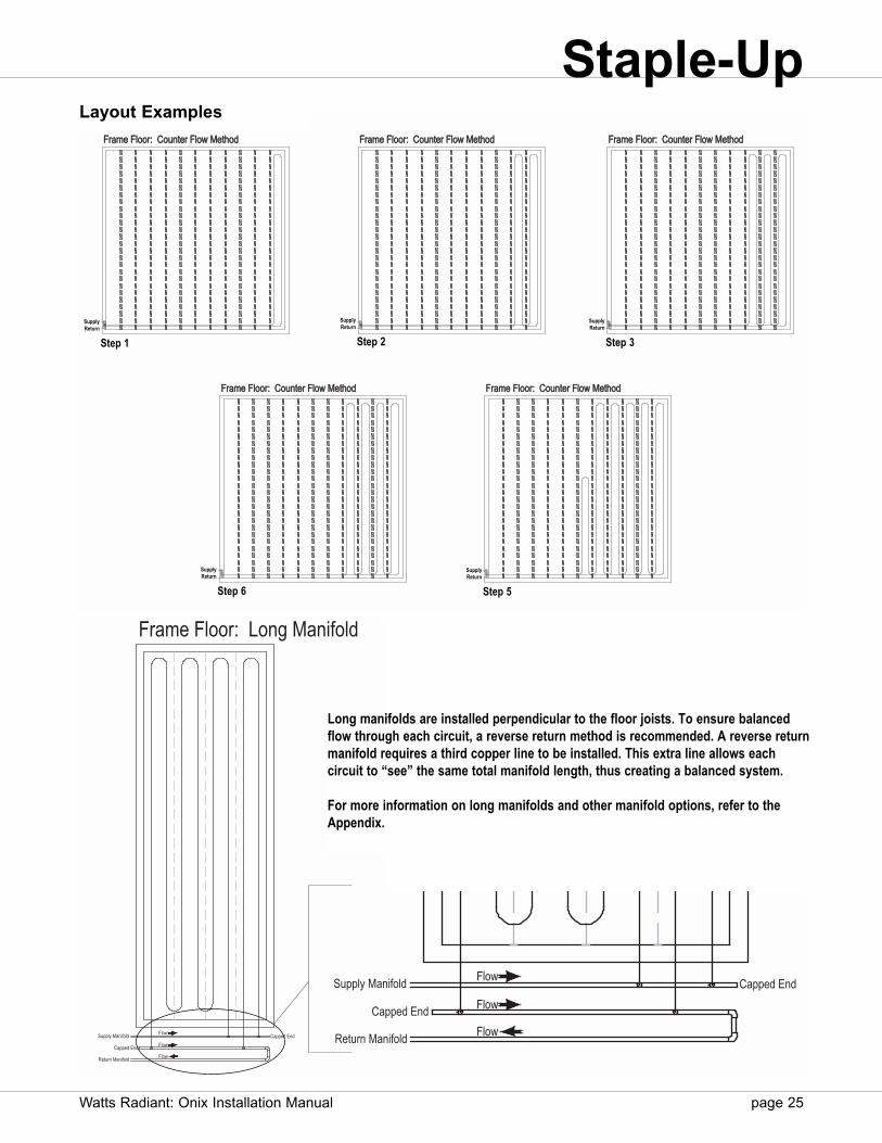
Stetep 5:
Frame F Floor: C: Counteter Flow w MeMethod
Return Manifold
Supply y Manifold
Frame F Floor: C: Counteter Flow w MeMethod
Stetep 4:
Supply y Manifold
Return Manifold
Stetep 3:
Return Manifold
Supply y Manifold
Frame F Floor: C: Counteter Flow w MeMethod
Stetep 2:
Supply y Manifold
Return Manifold
Frame F Floor: C: Counteter Flow w MeMethod
Stetep 1
Return Manifold
Supply y Manifold
Frame F Floor: C: Counteter Flow w MeMethod
Frame Floor: Long Manifold
Flow
Flow
Flow
Capped End
Capped EndSupply Manifold
Return Manifold
Long manifolds are installed perpendicular to the floor joists. To ensure balancedflow through each circuit, a reverse return method is recommended. A reverse returnmanifold requires a third copper line to be installed. This extra line allows each circuit to “see” the same total manifold length, thus creating a balanced system.
For more information on long manifolds and other manifold options, refer to theAppendix.
Flow
Flow
Flow
Capped End
Capped EndSupply Manifold
Return Manifold
Layout Examples
Watts Radiant: Onix Installation Manual page 25
Staple-Up
SupplyReturn
Step 1
SupplyReturn
Step 2
SupplyReturn
Step 3
SupplyReturn
Step 5
SupplyReturn
Step 6
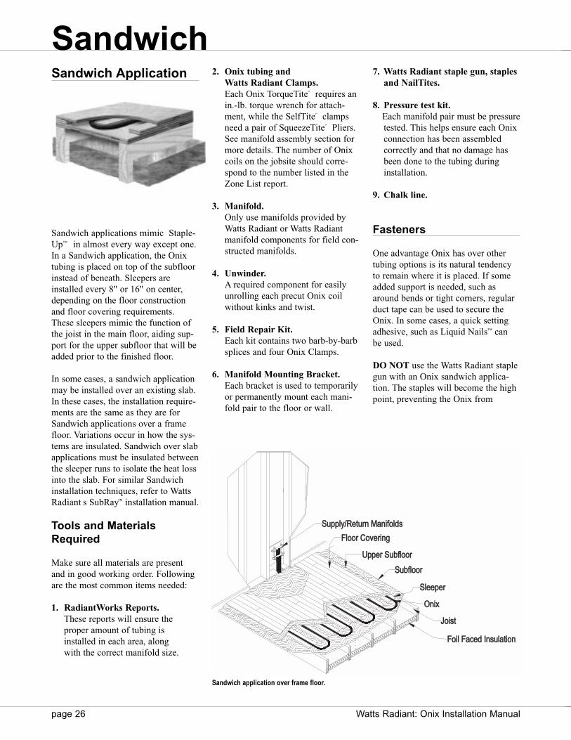
2. Onix tubing and Watts Radiant Clamps.Each Onix TorqueTite“ requires anin.-lb. torque wrench for attach-ment, while the SelfTite“ clampsneed a pair of SqueezeTite“ Pliers.See manifold assembly section formore details. The number of Onixcoils on the jobsite should corre-spond to the number listed in theZone List report.
3. Manifold.Only use manifolds provided byWatts Radiant or Watts Radiantmanifold components for field con-structed manifolds.
4. Unwinder.A required component for easilyunrolling each precut Onix coilwithout kinks and twist.
5. Field Repair Kit.Each kit contains two barb-by-barbsplices and four Onix Clamps.
6. Manifold Mounting Bracket.Each bracket is used to temporarilyor permanently mount each mani-fold pair to the floor or wall.
7. Watts Radiant staple gun, staplesand NailTites.
8. Pressure test kit.Each manifold pair must be pressure tested. This helps ensure each Onix connection has been assembled correctly and that no damage has been done to the tubing during installation.
9. Chalk line.
Fasteners
One advantage Onix has over othertubing options is its natural tendencyto remain where it is placed. If someadded support is needed, such asaround bends or tight corners, regularduct tape can be used to secure theOnix. In some cases, a quick settingadhesive, such as Liquid Nails™ can be used.
DO NOT use the Watts Radiant staplegun with an Onix sandwich applica-tion. The staples will become the highpoint, preventing the Onix from
Sandwich Application
Sandwich applications mimic Staple-Up™ in almost every way except one.In a Sandwich application, the Onixtubing is placed on top of the subfloorinstead of beneath. Sleepers areinstalled every 8" or 16" on center,depending on the floor constructionand floor covering requirements.These sleepers mimic the function ofthe joist in the main floor, aiding sup-port for the upper subfloor that will beadded prior to the finished floor.
In some cases, a sandwich applicationmay be installed over an existing slab.In these cases, the installation require-ments are the same as they are forSandwich applications over a framefloor. Variations occur in how the sys-tems are insulated. Sandwich over slabapplications must be insulated betweenthe sleeper runs to isolate the heat lossinto the slab. For similar Sandwichinstallation techniques, refer to WattsRadiant s SubRay™ installation manual.
Tools and MaterialsRequired
Make sure all materials are presentand in good working order. Followingare the most common items needed:
1. RadiantWorks Reports.These reports will ensure the proper amount of tubing is installed in each area, along with the correct manifold size.
page 26 Watts Radiant: Onix Installation Manual
SupSupplyply/Return Mananifololdsds
Flooror CovCovereringng
UppUpperer SubSubfloorloor
SubSubfloorloor
Oninix
Joisoist
Foiloil FaFaced d Insulationon
SlSleepeperer
Sandwich application over frame floor.
Sandwich

contacting the subfloor. This willreduce the heat transfer potential ofthe system.
Installation Steps
Installation procedures change fromjob to job and are affected by how thestructure is built. Sleeper spacing,thickness and zoning details are just afew items that can affect how aSandwich application is installed. Thefollowing guidelines and examplescover the most common installationconditions. If unexpected circum-stances arise, please contact WattsRadiant or a Watts RadiantRepresentative.
The most common tube layout patternis a single serpentine, although insome cases a double serpentine maybe used.
Step 1: Install ManifoldsWith the use of Watts Radiant s mani-fold brackets or manifold mountingenclosure, secure the manifolds to thejoist or wall enclosure. If the mani-folds are located in a joist space, makeallowances for the Onix to transferthrough the wall base plate and intothe sleeper system. Follow local code
guidelines when penetrating framingbase (bottom) plates.
Step 2: Determine ZoneBoundariesBefore Onix is installed, visuallyinspect the area to determine the zoneboundaries. This helps determinewhere the first circuit is to be placed,while identifying any obstacles thatmay be in the way.
Step 3: Confirm TubingRequirementsMeasure the distance from the mani-folds to the farthest point in the zone.The minimum Onix circuit must be atleast twice this distance. If not, theOnix will not be long enough to reachthe farthest point and be able to returnto the manifold.
Step 4: Sleeper Placement and SizingFor this step, gather the followingtools: chalk line, marker, circular sawand sleepers. There are two main vari-ations to a Sandwich installation; eachis dependent on how the system willbe insulated. If the system is to beinsulated in the joist cavity, a 3/4"sleeper should be used with 3/8" Onix.If the system is to be insulated on top
of the subfloor, between the sleepers,then the sleeper height needs to bechosen based on the insulation heightto still allow a 3/4" space for the Onix.Most systems insulated on top of thesubfloor need a 2 x 4 sleeper with a3/4" insulation board.
Note: For best heat transfer, Onixshould be touching the upper sub-floor.
Place a position sleeper around thezone and all interior walls. This posi-tion sleeper will help keep the Onixaway from exterior and interior wallconstruction. This is important to helpprevent damage to the tubing that maybe cause by wall placement or floorcovering installation, such as carpetstrips or other anchor points.
If insulating below the floor in thejoist cavity, sleepers are usually 6"—7"wide, leaving a 1"—2" gap betweensleepers.
If insulating between the sleepers,sleepers are usually a standard 2 x 4leaving a 14"—16" gap between sleep-ers. This spacing is based on a stan-dard 3/4" subfloor being applied on
Watts Radiant: Onix Installation Manual page 27
Onix 2”x4” Sleeper
Board Insulation
Air Gap
3/4” SleeperFoil-Faced Fiberglass
Manifold Box and Cover Position
Sleeper
Air Gap
Joist side view showing Sandwich applicationusing rigid foil-faced polyisocyanurate insulation.
Joist side view showing Sandwich applicationusing foil-faced batt insulation.
Sandwich
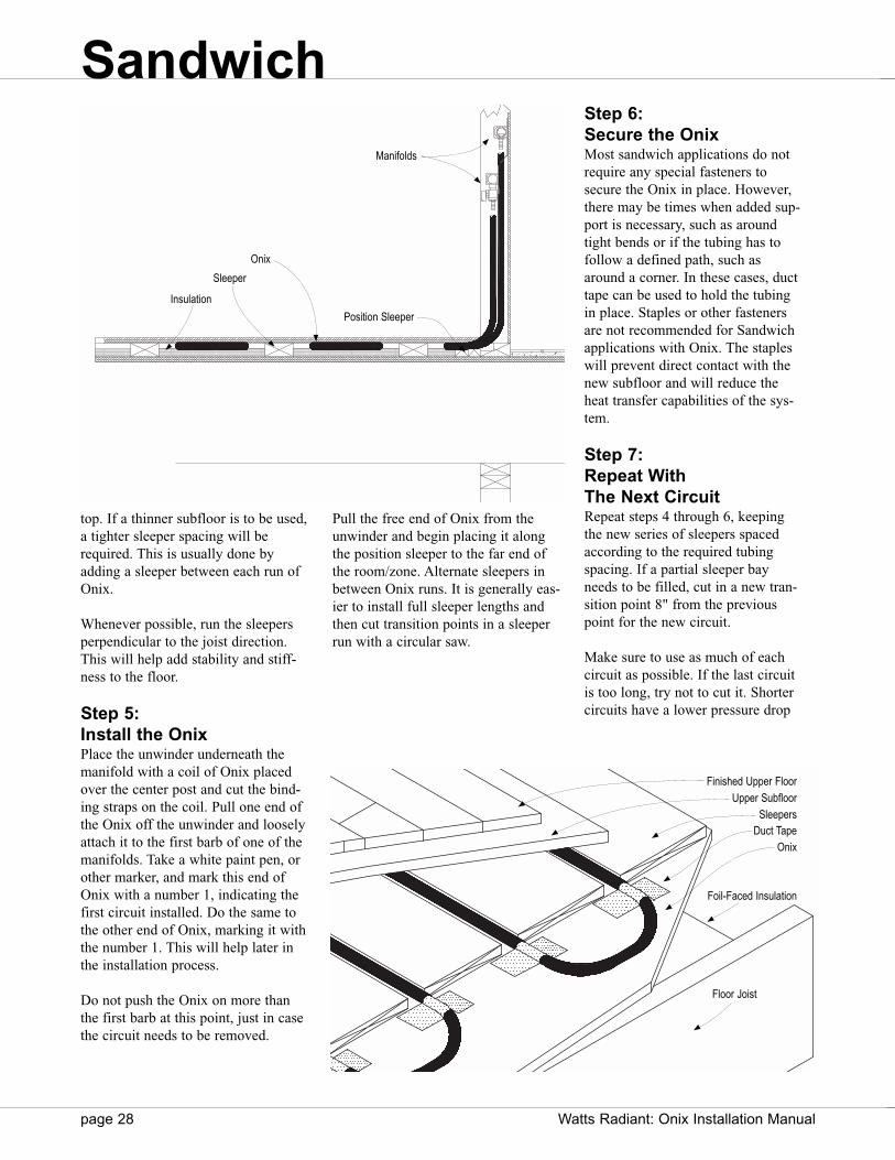
top. If a thinner subfloor is to be used,a tighter sleeper spacing will berequired. This is usually done byadding a sleeper between each run ofOnix.
Whenever possible, run the sleepersperpendicular to the joist direction.This will help add stability and stiff-ness to the floor.
Step 5: Install the OnixPlace the unwinder underneath themanifold with a coil of Onix placedover the center post and cut the bind-ing straps on the coil. Pull one end ofthe Onix off the unwinder and looselyattach it to the first barb of one of themanifolds. Take a white paint pen, orother marker, and mark this end ofOnix with a number 1, indicating thefirst circuit installed. Do the same tothe other end of Onix, marking it withthe number 1. This will help later inthe installation process.
Do not push the Onix on more thanthe first barb at this point, just in casethe circuit needs to be removed.
Pull the free end of Onix from theunwinder and begin placing it alongthe position sleeper to the far end ofthe room/zone. Alternate sleepers inbetween Onix runs. It is generally eas-ier to install full sleeper lengths andthen cut transition points in a sleeperrun with a circular saw.
Step 6: Secure the OnixMost sandwich applications do notrequire any special fasteners tosecure the Onix in place. However,there may be times when added sup-port is necessary, such as aroundtight bends or if the tubing has tofollow a defined path, such asaround a corner. In these cases, ducttape can be used to hold the tubingin place. Staples or other fastenersare not recommended for Sandwichapplications with Onix. The stapleswill prevent direct contact with thenew subfloor and will reduce theheat transfer capabilities of the sys-tem.
Step 7: Repeat With The Next CircuitRepeat steps 4 through 6, keepingthe new series of sleepers spacedaccording to the required tubingspacing. If a partial sleeper bayneeds to be filled, cut in a new tran-sition point 8" from the previouspoint for the new circuit.
Make sure to use as much of eachcircuit as possible. If the last circuitis too long, try not to cut it. Shortercircuits have a lower pressure drop
page 28 Watts Radiant: Onix Installation Manual
Finished Upper Floor
Upper SubfloorSleepers
OnixDuct Tape
Manifolds
Position Sleeper
Sleeper
Onix
Insulation
Foil-Faced Insulation
Floor Joist
Sandwich
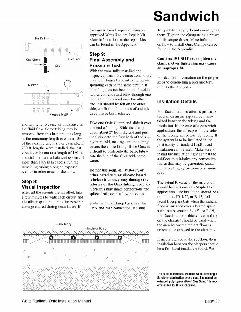
and will tend to cause an imbalance inthe fluid flow. Some tubing may beremoved from this last circuit as longas the remaining length is within 10%of the existing circuits. For example, if200 ft. lengths were installed, the lastcircuit can be cut to a length of 180 ft.and still maintain a balanced system. Ifmore than 10% is in excess, run theremaining tubing along an exposedwall or in other areas of the zone.
Step 8: Visual InspectionAfter all the circuits are installed, takea few minutes to walk each circuit andvisually inspect the tubing for possibledamage caused during installation. If
damage is found, repair it using anapproved Watts Radiant Repair Kit.More information on the repair kitscan be found in the Appendix.
Step 9: Final Assembly andPressure TestWith the zone fully installed andinspected, finish the connections to themanifold. Begin by identifying corre-sponding ends to the same circuit. Ifthe tubing has not been marked, selecttwo circuit ends and blow through one,with a thumb placed over the otherend. Air should be felt on the otherside, confirming both ends of a singlecircuit have been selected.
Take one Onix Clamp and slide it overone end of tubing. Slide the clampdown about 2" from the end and pushthe Onix onto the first barb of the sup-ply manifold, making sure the tubingcovers the entire fitting. If the Onix isdifficult to push onto the barb, lubri-cate the end of the Onix with somewater.
Do not use soap, oil, WD-40®, orother petroleum or silicone basedlubricants as they may damage theinterior of the Onix tubing. Soap andlubricants may make connections andsplices leak, even at low pressures.
Slide the Onix Clamp back over theOnix and barb connection. If using
TorqueTite clamps, do not over-tightenthem. Tighten the clamp using a presetin.-lb. torque driver. More informationon how to install Onix Clamps can befound in the Appendix.
Caution: DO NOT over tighten theclamps. Over tightening may causean improper fit.
For detailed information on the propersteps to conducting a pressure test,refer to the Appendix.
Insulation Details
Foil-faced batt insulation is primarilyused when an air gap can be main-tained between the tubing and theinsulation. In the case of a Sandwichapplication, the air gap is on the sidesof the tubing, not below the tubing. Ifthe system is to be insulated in thejoist cavity, a standard Kraft facedinsulation can be used. Make sure toinstall the insulation tight against thesubfloor to minimize any convectivelosses that may be generated. (note:this is a change from previous manu-als.)
The actual R-value of the insulationshould be the same as a Staple Up™
application. The insulation should be aminimum of 3-1/2", or R-13, foil-faced fiberglass batt when the radiantfloor is installed over a heated space,such as a basement. 5-1/2", or R-19,foil-faced batts (or thicker, dependingon the climate) should be used whenthe area below the radiant floor isunheated or exposed to the elements.
If insulating above the subfloor, theninsulation between the sleepers shouldbe a foil faced insulation board. We
Watts Radiant: Onix Installation Manual page 29
Manifold
Onix BarbOnix Clamp
Onix
Manifold
Pressure Test Kit
The same techniques are used when installing aSandwich application over a slab. The use of anextruded polystyrene (Dow® Blue Board®) is rec-ommended for this application.
Onix TubingInsulation Board
Sandwich
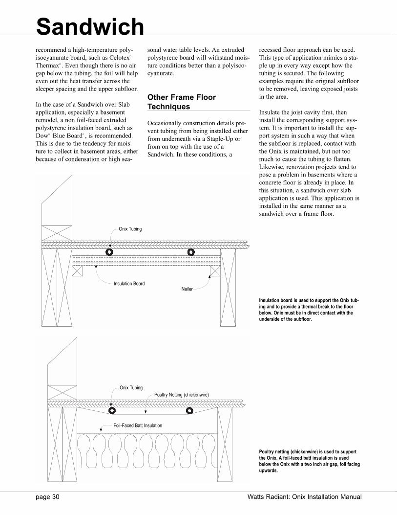
recommend a high-temperature poly-isocyanurate board, such as Celotex¤
Thermax¤ . Even though there is no airgap below the tubing, the foil will helpeven out the heat transfer across thesleeper spacing and the upper subfloor.
In the case of a Sandwich over Slabapplication, especially a basementremodel, a non foil-faced extrudedpolystyrene insulation board, such asDow¤ Blue Board¤ , is recommended.This is due to the tendency for mois-ture to collect in basement areas, eitherbecause of condensation or high sea-
recessed floor approach can be used.This type of application mimics a sta-ple up in every way except how thetubing is secured. The followingexamples require the original subfloorto be removed, leaving exposed joistsin the area.
Insulate the joist cavity first, theninstall the corresponding support sys-tem. It is important to install the sup-port system in such a way that whenthe subfloor is replaced, contact withthe Onix is maintained, but not toomuch to cause the tubing to flatten.Likewise, renovation projects tend topose a problem in basements where aconcrete floor is already in place. Inthis situation, a sandwich over slabapplication is used. This application isinstalled in the same manner as asandwich over a frame floor.
page 30 Watts Radiant: Onix Installation Manual
Insulation board is used to support the Onix tub-ing and to provide a thermal break to the floorbelow. Onix must be in direct contact with theunderside of the subfloor.
Poultry netting (chickenwire) is used to supportthe Onix. A foil-faced batt insulation is usedbelow the Onix with a two inch air gap, foil facingupwards.
Onix Tubing
Insulation BoardNailer
Foil-Faced Batt Insulation
Onix TubingPoultry Netting (chickenwire)
sonal water table levels. An extrudedpolystyrene board will withstand mois-ture conditions better than a polyisco-cyanurate.
Other Frame FloorTechniques
Occasionally construction details pre-vent tubing from being installed eitherfrom underneath via a Staple-Up orfrom on top with the use of aSandwich. In these conditions, a
Sandwich

Watts Radiant: Onix Installation Manual page 31
Walls and Ceilings
Radiant floors produce a limitedamount of energy, usually around 45—50 BTU/sq.ft. This limit is set by themaximum floor surface temperature of85¡F. Most of the time this will beseen in areas like sunrooms. In caseslike this where auxiliary heat isrequired, supplemental heat may beadded in the form of baseboards or fancoils.
Or, supplemental heat may be addedby simply increasing the radiant sur-face area.
Tubing can be installed in an interiorwall or ceiling to increase the radiantsurface area for a given room.
Walls and ceiling panels may also beused in cases where installation pro-hibits a radiant floor installation.
Installation requirements are the samefor both ceiling and walls as seen inother frame applications.
If Watts Radiant s SubRay product isto be used for the ceilings or walls,consult the SubRay installation manualfor further details.
Caution: In all wall or ceiling appli-cations, Onix must be installed so itis in contact with the wall or ceiling.
Poultry Netting
Poultry Netting (chicken wire) can beused to support the Onix in the wallcavity. Only install a radiant system inan interior wall. Exterior walls canhave potentially higher back and edgelosses and will increase the risk offreezing in the case of a power failure.
Foil-faced insulation should beinstalled first with the foil facing thetubing. Poultry netting is then installedover the joists with just enough slackto allow the wire some movementback into the wall cavity.
Onix is attached to the netting with theuse of cable ties and spaced either on8" or 4" centers. It is important not toallow the tubing to go higher than 4’
Wall Stud/Ceiling Joist
PoultryNetting Onix
Supply/Return Manifolds
Interior Wall
Interior Wall
Onix (Cross Section)
Poultry Netting
Foil-Faced Batt InsulationWall Stud/Ceiling Joist
Walls and Ceilings
Onix transitioning from one joist/stud bay to the next
Typical wall or ceiling application using poultry netting (chicken wire).
Cross section of a wall or ceiling application using poultry netting (chicken wire).
16”o.c.
8”o.c.
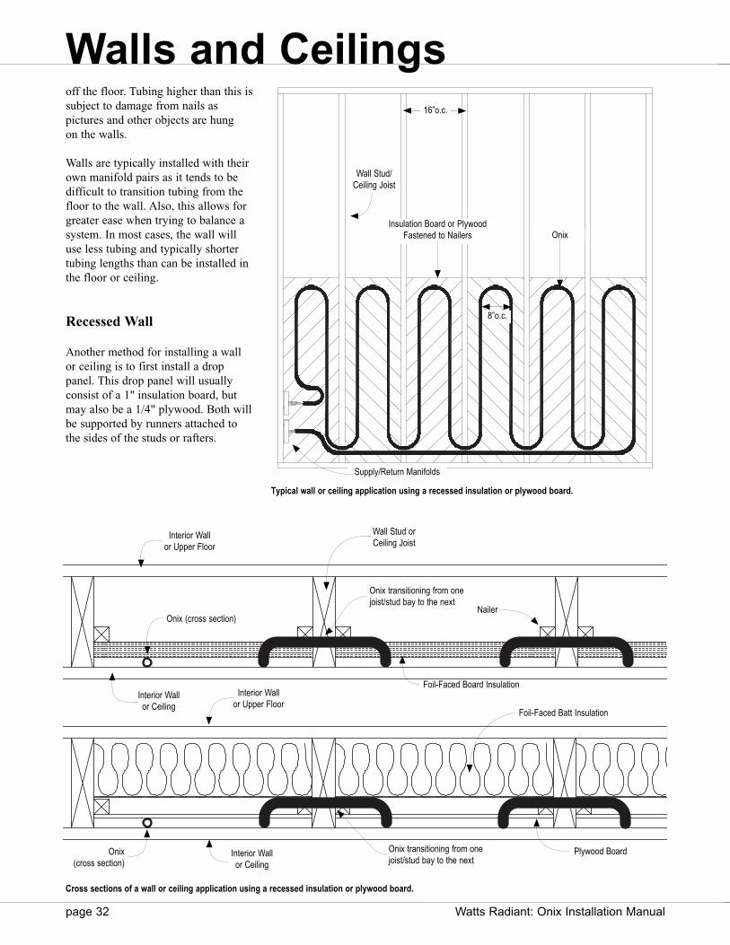
page 32 Watts Radiant: Onix Installation Manual
off the floor. Tubing higher than this issubject to damage from nails as pictures and other objects are hung on the walls.
Walls are typically installed with theirown manifold pairs as it tends to bedifficult to transition tubing from thefloor to the wall. Also, this allows forgreater ease when trying to balance asystem. In most cases, the wall willuse less tubing and typically shortertubing lengths than can be installed inthe floor or ceiling.
Recessed Wall
Another method for installing a wallor ceiling is to first install a droppanel. This drop panel will usuallyconsist of a 1" insulation board, butmay also be a 1/4" plywood. Both willbe supported by runners attached tothe sides of the studs or rafters.
Wall Stud/Ceiling Joist
Insulation Board or PlywoodFastened to Nailers Onix
Supply/Return Manifolds
Interior Wallor Upper Floor
Interior Wallor Ceiling
Onix (cross section)Nailer
Foil-Faced Board Insulation
Wall Stud orCeiling Joist
Interior Wallor Ceiling
Plywood Board
Foil-Faced Batt Insulation
Onix transitioning from one joist/stud bay to the next
Typical wall or ceiling application using a recessed insulation or plywood board.
Cross sections of a wall or ceiling application using a recessed insulation or plywood board.
Interior Wallor Upper Floor
Onix transitioning from one joist/stud bay to the next
Onix(cross section)
16”o.c.
8”o.c.
Walls and Ceilings

Watts Radiant: Onix Installation Manual page 33
If a plywood drop board is used, afoil-faced insulation needs to be installbehind the plywood.
SubRay¤
In some cases, the wall or ceiling cavi-ty may not be deep enough to allowfor the Onix, insulation and supportmaterial. In these cases, Watts RadiantSubRay can be used. This will go ontop of the wall studs or ceiling joists.
A 2 × 4 support plate will need to beadded to either end of the wall to helpsecure the Header Stick. Make sure toselect the 18 mm SubRay product toaccommodate the 3/8" Onix tubing.
Wall Stud/Ceiling Joist
Support forHeader Stick
Onix
Sleeper
Supply/Return Manifolds
Header Stick and Corner Sweep
Header Stick
Gripper
16”o.c.
Walls and Ceilings
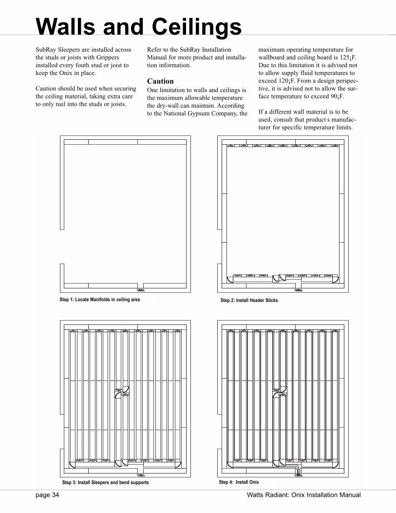
page 34 Watts Radiant: Onix Installation Manual
SubRay Sleepers are installed acrossthe studs or joists with Grippersinstalled every fouth stud or joist tokeep the Onix in place.
Caution should be used when securingthe ceiling material, taking extra careto only nail into the studs or joists.
Step 1: Locate Manifolds in ceiling area Step 2: Install Header Sticks
Step 3: Install Sleepers and bend supports Step 4: Install Onix
Refer to the SubRay InstallationManual for more product and installa-tion information.
CautionOne limitation to walls and ceilings isthe maximum allowable temperaturethe dry-wall can maintain. Accordingto the National Gypsum Company, the
maximum operating temperature forwallboard and ceiling board is 125¡F.Due to this limitation it is advised notto allow supply fluid temperatures toexceed 120¡F. From a design perspec-tive, it is advised not to allow the sur-face temperature to exceed 90¡F.
If a different wall material is to beused, consult that product s manufac-turer for specific temperature limits.
Walls and Ceilings
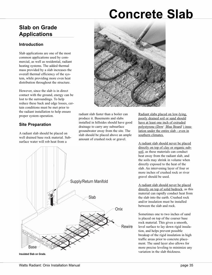
Slab on GradeApplications
Introduction
Slab applications are one of the mostcommon applications used by com-mercial, as well as residential, radiantheating systems. The added thermalmass provided by a slab increases theoverall thermal efficiency of the sys-tem, while providing more even heatdistribution throughout the structure.
However, since the slab is in directcontact with the ground, energy can belost to the surroundings. To helpreduce these back and edge losses, cer-tain conditions must be met prior tothe radiant installation to help ensureproper system operation.
Site Preparation
A radiant slab should be placed onwell drained base rock material. Sub-surface water will rob heat from a
radiant slab faster than a boiler canproduce it. Basements and slabsinstalled in hillsides should have gooddrainage to carry any subsurfacegroundwater away from the site. Theslab should be placed above an ampleamount of crushed rock or gravel.
Watts Radiant: Onix Installation Manual page 35
Radiant slabs placed on low-lying,poorly drained soil or sand shouldhave at least one inch of extrudedpolystyrene (Dow¤ Blue Board¤ ) insu-lation under the entire slab - even insouthern climates.
A radiant slab should never be placeddirectly on top of clay or organic sub-soil, as these materials can conductheat away from the radiant slab, andthe soils may shrink in volume whendirectly exposed to the heat of theslab. An intervening layer of four ormore inches of crushed rock or rivergravel should be used.
A radiant slab should never be placeddirectly on top of solid bedrock, as thismaterial can rapidly conduct heat fromthe slab into the earth. Crushed rockand/or insulation must be installedbetween the slab and rock.
Sometimes one to two inches of sandis placed on top of the coarser baserock material. This gives a smooth,level surface to lay down rigid insula-tion, and helps prevent possiblebreakup of the rigid insulation in hightraffic areas prior to concrete place-ment. The sand layer also allows formore precise leveling to minimize anyvariation in the slab thickness.
Supply/Return Manifold
Slab
Onix
Rewire
Base
Insulated Slab on Grade.
Concrete Slab

Insulation Details
Unlike a frame application where theinsulation is installed after the radianttubing, a slab application requires theinsulation to be installed first, makingthe insulation part of the structure.
In a slab on grade application there aretwo main areas to insulate: verticallyaround the perimeter of the slab andhorizontally underneath the slab. Bothwill aid in the slab s response and efficiency. Of these two, the verticaledge insulation is the most importantbecause it prevents heat loss directlyto the outside environment. Horizontalinsulation helps decrease the slab srequired start up time by isolating theheating mass from the ground massbelow. Typically the system will see areduction of about 10% in overalloperational efficiency if a horizontalinsulation is not used.
Type of Insulation
Extruded polystyrene insulation boardis recommended mainly because theinsulation board will be in direct con-tact with the soil. Extruded poly-
styrene insulation will not degradeover time due to excess moisture orsoil acidity. Beaded insulationboards should not be used becausethey are not strong enough and willbreak down over time. This, in turn,will cause structural instability.
In most applications, 1" insulationboard is recommended. A thickerboard may be used if the slab is to beinstalled in a cold, aggressive climate.Always check with an architect orstructural engineer to ensure theappropriate insulation is used.
Foil-faced insulation is not required orrecommended when insulating a radi-ant slab. Foil-faced insulation is usedwhen an air gap is able to be main-tained. In the case of a slab applicationthe tubing is completely encapsulatedin the concrete, eliminating any airgap.
Watts Radiant does not recommendBubble-type insulation under a slabapplication until more research hasbeen done and performance hasbeen verified.
Special ConstructionConsiderations
Slab applications are generally the eas-iest to install. However, it is importantto remember what type of constructionsteps remain after the concrete slabhas been poured. In most projects, theconcrete is the first phase of the proj-ect. Interior walls and other supportsstructures still have to be installed,most being mounted or secured direct-ly to the slab. With this in mind, it isimportant to take some preliminarysteps to help protect the tubing duringconstruction.
Control Joints
Concrete slabs will expand and con-tract due to thermal changes. To pre-vent damage to the slab, expansionjoints are used to control this move-ment. In some cases cut joints are usedto control where cracking is to occur.Make sure the tubing is protectedaccording to the requirements of thecontrol joint.
Design Parameters
For proper radiant design it is impor-tant know the type of layers used inthe floor construction. As these layersincrease or change, variances in theheating system are required. Concreteis a very conductive material, allowingfor a wider spread in heat transferthroughout the mass. However, certainlimitations should be present to ensurecertain comfort levels are maintained.
Onix Spacing
Most residential slabs will use 12"tube spacing with some perimeterbanding. In a few cases, where controlover supply fluid temperature is need-ed, an entire room may be installed at6" on center. This may be the case in ahigh heat loss sunroom or pool area.
page 36 Watts Radiant: Onix Installation Manual
InsulationBoard
Subgrade
Onix
ConcreteRewire/Rebar
Concrete Slab
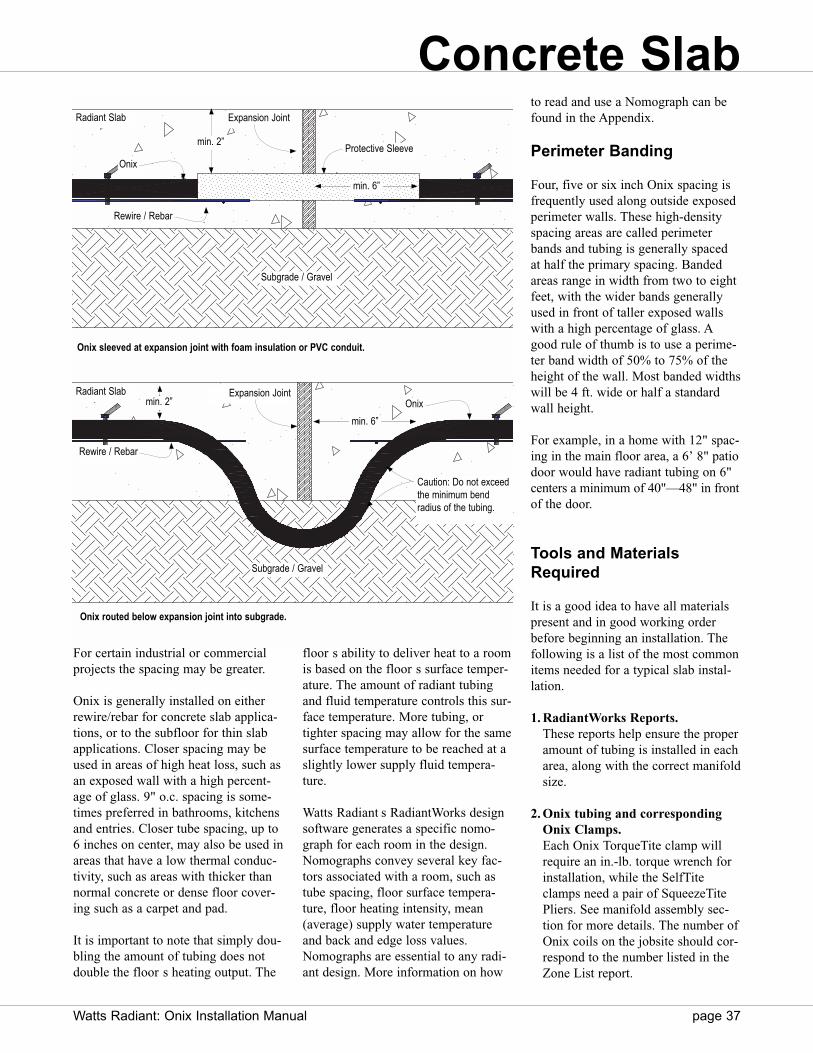
For certain industrial or commercialprojects the spacing may be greater.
Onix is generally installed on eitherrewire/rebar for concrete slab applica-tions, or to the subfloor for thin slabapplications. Closer spacing may beused in areas of high heat loss, such asan exposed wall with a high percent-age of glass. 9" o.c. spacing is some-times preferred in bathrooms, kitchensand entries. Closer tube spacing, up to6 inches on center, may also be used inareas that have a low thermal conduc-tivity, such as areas with thicker thannormal concrete or dense floor cover-ing such as a carpet and pad.
It is important to note that simply dou-bling the amount of tubing does notdouble the floor s heating output. The
floor s ability to deliver heat to a roomis based on the floor s surface temper-ature. The amount of radiant tubingand fluid temperature controls this sur-face temperature. More tubing, ortighter spacing may allow for the samesurface temperature to be reached at aslightly lower supply fluid tempera-ture.
Watts Radiant s RadiantWorks designsoftware generates a specific nomo-graph for each room in the design.Nomographs convey several key fac-tors associated with a room, such astube spacing, floor surface tempera-ture, floor heating intensity, mean(average) supply water temperatureand back and edge loss values.Nomographs are essential to any radi-ant design. More information on how
to read and use a Nomograph can befound in the Appendix.
Perimeter Banding
Four, five or six inch Onix spacing isfrequently used along outside exposedperimeter walls. These high-densityspacing areas are called perimeterbands and tubing is generally spacedat half the primary spacing. Bandedareas range in width from two to eightfeet, with the wider bands generallyused in front of taller exposed wallswith a high percentage of glass. Agood rule of thumb is to use a perime-ter band width of 50% to 75% of theheight of the wall. Most banded widthswill be 4 ft. wide or half a standardwall height.
For example, in a home with 12" spac-ing in the main floor area, a 6’ 8" patiodoor would have radiant tubing on 6"centers a minimum of 40"—48" in frontof the door.
Tools and MaterialsRequired
It is a good idea to have all materialspresent and in good working orderbefore beginning an installation. Thefollowing is a list of the most commonitems needed for a typical slab instal-lation.
1. RadiantWorks Reports.These reports help ensure the properamount of tubing is installed in eacharea, along with the correct manifoldsize.
2. Onix tubing and correspondingOnix Clamps.Each Onix TorqueTite clamp willrequire an in.-lb. torque wrench forinstallation, while the SelfTiteclamps need a pair of SqueezeTitePliers. See manifold assembly sec-tion for more details. The number ofOnix coils on the jobsite should cor-respond to the number listed in theZone List report.
Watts Radiant: Onix Installation Manual page 37
Onix routed below expansion joint into subgrade.
Radiant Slab
Radiant Slab
Expansion Joint
Onix
Rewire / Rebar
Protective Sleeve
Subgrade / Gravel
Expansion JointOnix
Rewire / Rebar
Subgrade / Gravel
Onix sleeved at expansion joint with foam insulation or PVC conduit.
min. 6”
min. 2”
Caution: Do not exceedthe minimum bendradius of the tubing.
min. 2”
min. 6”
Concrete Slab

page 38 Watts Radiant: Onix Installation Manual
3. Manifold.Only use Watts Radiant manifolds or manifold components for field-constructed manifolds.
4. Unwinder.A required component for easilyunrolling each precut Onix coilwithout kinks and twist.
5. Field Repair Kit.Each kit will contain two barb-by-barb splices and four Onix Clamps.
6. Manifold Mounting Bracket.Each bracket can be used to temporarily or permanently mounteach manifold pair to the floor orwall. Use either Watts Radiantbrackets or SnapClips™ to hold manifolds.
7. Watts Radiant staple gun, staplesand NailTites.
8. Pressure test kit.Each manifold pair must be pressuretested. This helps ensure each Onixconnection has been installed cor-rectly and to make sure no addition-al damage has been done to the tub-ing during installation.
9. Installation Accessoriesa. Spray Paint - for marking
out zones and subzones, as well as areas not to be heated.
b. Electrical Tape - for temporarily mounting the manifolds or taping ends of tubing together.
c. Cable Ties, ClipTies®, ScrewClips™ or other fasteners.
Since rewire/rebar is commonly usedin concrete slabs for structural integri-ty, it is common practice to attachOnix to the rewire/rebar. This is com-
monly done with the use of nyloncable ties or Watts Radiant ClipTiesand Clipper tool. Each secures theOnix to the rewire/rebar to preventmovement of the tubing during theconcrete pour.
In applicationswhere rewire/rebar isnot used and an insu-lation board isplaced underneaththe slab, some addi-tional attachmentdevices can be usedto secure the Onix.Watts Radiant sFoam Staples orFoam Clips can beused to secure theOnix tubing directlyto the insulationboard. StandardOnix staples can beused if a thin slab isinstalled over awood subfloor.
For any attachmentmethod, it is impor-tant to secure thetubing at least every 12" to 18" oncenter. This will prevent the Onix fromshifting during the concrete pour. (SeeWatts Radiant catalog or binder formore information on fasteners andtools.)
Slab Profile andGeneral Details
In slab-on-grade applications, it isimportant to maintain at least 2"—3" ofconcrete covering above the tubing.More coverage may be necessarydepending on the structural require-ments of the slab. The 2"—3" coverageis to ensure structural stability withinthe slab, allow for cut joints or framewalls to be applied and to allowenough space to float the aggregate.
FoamBoard Stapler™
ClipTwister™ Tool
Return Manifold
Supply Manifold
SlabExposed Wall
Banded Tubing
Inte
rior W
all
Primary Tubing
Typical slab tubing layout.
Concrete Slab
Supply Manifold
Return Manifold

Watts Radiant: Onix Installation Manual page 39
Consult with the project manager orconcrete installer to make sure thisdepth is appropriate.
Complete encapsulation of the tubingis required to prevent stress pointsfrom forming on the slab, which mayaccelerate cracking over time.
Installation Steps
Manifold locations, final concretethickness and zoning details are just afew items that are required for a suc-cessful radiant slab installation. Thefollowing guidelines and examplescover the most common installationconditions. If your situation is not cov-ered here or if unexpected circum-stances arise, please contact WattsRadiant or a Watts RadiantRepresentative.
The most common installation patternfor slab applications is a double ser-pentine layout, although in some casesa single serpentine may be used.
Step 1: Pre-Pour Conditions
Verify all subgrade conditions areproperly prepared, all insulation isinstalled according to design condi-tions and rewire or rebar is in place.With orange spray paint, locate allinterior walls and other obstacles thatmay need to be avoided, such as toiletareas, sewer drains, and any structuralsupports that may penetrate the slab.
Step 2: Install Manifolds
Locate where the manifolds are to beinstalled. Drive two pieces of rebarvertically into the ground at this loca-tion. With the use of cable ties or elec-trical tape, temporarily secure themanifolds to the rebar. Remember tokeep the manifolds high enough toallow for the thickness of the concrete,the interior wall base plate and otherstructural items that may need to beinstalled after the pour.
Secure manifolds torebar or other support
Unwind the Onix to form aloop and attach ends to themanifolds
Lay Onix across slab area,keeping tubing spaced todesign conditions.
Secure Onix every 18” oncenter to the rewire or rebar.
Concrete Slab
Typical slab installation. Onix is installed using a double serpentine pattern.
Vertical Edge insulation isrequired along all exposedsides of the slab.
Horizontal Insulation should beinstalled under the entire slabfor optimum performance. Forcommercial and some residen-tial applications, horizontal insu-lation can be limited to theexposed perimeter.

After the concrete is poured and justbefore the interior walls are installed,the rebar may be cut to free the mani-folds. The manifolds can then bemoved if necessary, to fit the actualwall construction. Make sure to leaveplenty of slack in all Onix circuits (2–5 ft. is recommended). A WattsRadiant manifold box can be used tosecure the manifolds within the newwall. Watts Radiant SnapClips andStrapDowns can be used to organizeOnix coming from the floor and intothe wall.
Step 3: Determine ZoneBoundaries
Before Onix is installed, visuallyinspect the area to determine the zoneboundaries. This helps determinewhere the first circuit is to be placed,while identifying any obstacles thatmay be in the way.
Step 4: Confirm TubingRequirements
Measure the distance from the mani-folds to the farthest point in the zone.Make sure the minimum circuit lengthis at lest twice this distance. If not, theOnix will not be long enough to reachthe farthest point of the zone andreturn.
Step 5: Install the Onix
Place the unwinder underneath themanifold with a coil of Onix placedover the center post and cut the bind-ing straps on the coil. Pull one end ofthe Onix off the unwinder until theentire coil is unwound. Loop the coilso the two ends meet back together,forming a loop. Loosely attach bothends of the coil to the manifolds, oneto the supply and one to the returnmanifold. Take a white paint pen, orother marker, and mark each end ofOnix with a number 1, indicating thefirst circuit installed. This will helplater in the installation process.
Do not push the Onix on more thanthe first barb at this point, just in casethe circuit needs to be removed. Takeboth runs of Onix and begin layingboth sides of the circuit in the slabarea. This method will naturally createa double serpentine layout. Continue
this process with the next circuit,beginning where the first circuit ends.
Begin at the manifold and grasp bothruns of the Onix loop, maintaining ahand spacing approximately the samedistance apart as the desired tube spac-ing. This spacing should be the sameas indicated in the design.
Lay the first run of Onix along theperimeter walls to the farthest point inthe zone, keeping the Onix 6-8" fromthe edge of the slab. This will helpprotect the tubing from possible pene-trations later on when the interior andexterior walls are installed. Onix canbe run underneath interior walls aslong as the Onix is deep enough in theslab to prevent nails in wall platesfrom damaging the circuits. Continueuntil the middle of the circuit isreached.
Typical slab application.Onix tubing installed 12”o.c. in a double serpentine pattern.
Concrete Slab
page 40 Watts Radiant: Onix Installation Manual

This double serpentine layout placesthe cooler return end of the circuitnext to the warmer supply end. Thislayout helps bring the finished floorsurface to an even temperature in theshortest time possible.
Unless the zone has only one loop orhas a very short exterior perimeter, donot heat more than half of the perime-ter with one circuit.
Step 6: Securing the Onix
Slab applications usually require someform of fastener, depending on theconstruction details. Most slab applica-tions use rewire or rebar to addstrength or crack resistance to the slab.In this application, the Onix attachesdirectly to the rewire/rebar by the useof cable ties or ClipTie clips. If theslab is poured without therewire/rebar, other fasteners can beused that will secure the Onix directlyto the foam insulation beneath theslab.
After no more than three circuits havebeen roughly laid out, tie downenough of the bends in the circuits totemporarily hold the Onix in place.Lay out all of the remaining circuits inthe zone before tying down more thanthe bends. This helps eliminate timeand wasted fasteners in the event cir-cuits need to be moved or adjusted.Repeat this process until all of the cir-
cuits with the zone are in position.Leave 2’—5’ slack on each circuit incase the manifold position needs to beadjusted from its temporary location.
After all circuits are in place and anyadjustments have been made, fastenthe Onix to the wire mesh or insula-tion board every one to two feet. Thiswill keep the Onix from shifting orfloating during the concrete pour. Ifcable ties are used, do not pull the tiesso tight that the Onix is flattened orpinched shut. Also, make sure alltails of the cable ties are either cut
off or turned downward to prevent anyunwanted surface protrusions.
Step 7: Repeat With The NextCircuit
Repeat steps 4 through 6, keeping thenext circuit spaced according to thedesign. Make sure to use as much ofeach circuit as possible. If the last cir-cuit is too long, which sometimes hap-pens, try not to cut it to make it short-er. Shorter circuits have a lower pres-sure drop and will tend to cause animbalance in the fluid flow. Some tub-ing may be removed from this last cir-cuit as long as the remaining length iswithin 10% of the existing circuits.For example, if 200 ft. lengths wereinstalled, the last circuit can be cut to alength of 180 ft. and still maintain abalanced system. If more than 10% is
Watts Radiant: Onix Installation Manual page 41
in excess, run the remaining tubingalong an exposed wall or in otherareas of the zone.
Step 8: Visual Inspection
After all circuits are installed, take afew minutes to walk each circuit andvisually inspect the tubing for possibledamage caused during installation. If adamaged area is found, repair it usingan approved Watts Radiant Repair Kit.More information on repair kits can befound in the Appendix.
Step 9: Final Assembly andPressure Test
With the zone fully installed andinspected, finish the connections to themanifold. Begin by identifying corre-sponding ends to the same circuit. Ifthe tubing has not been marked, selecttwo circuit ends and blow through one,with a thumb placed over the otherend. Air should be felt on the otherside, confirming a single circuit hasbeen selected.
Take one Onix Clamp and slide it overone end of tubing. Slide the clampdown about 2" from the end and push
Manifold
Onix BarbOnix Clamp
Onix
Manifold
Pressure Test Kit
Rewire/Rebar
RailwayCable Tie
ScrewClip
ClipTie
FoamBoard Staple
Insulation
Subgrade/Earth
Slab
Various tube fasteners for slab applications.
Concrete Slab

page 42 Watts Radiant: Onix Installation Manual
the Onix onto the first barb of the sup-ply manifold, making sure the tubingcovers the entire fitting. If the Onix isdifficult to push onto the barb, lubri-cate the end of the Onix with somewater.
Do not use soap, oil, WD-40®, orother petroleum or silicone basedlubricants as they may damage theinterior of the Onix tubing. Soap orlubricants may make connections andsplices leak, even at low pressures.
Slide the Onix clamp back over theOnix hose and barb connection. Ifusing TorqueTite clamps, do not over-tighten. Tighten the TorqueTite clampusing a preset torque driver accordingto the settings stated on the instruc-tions that come with the clamps. Moreinformation on how to apply the Onixclamp connections can be found in theAppendix.
Caution: DO NOT over tighten theclamps. Over tightening may causean improper fit.
For detailed information on the propersteps to conducting a pressure test,refer to the Appendix of the installa-tion manual.
Step 10: The Concrete Pour
To help detect possible damage causedduring the concrete pour, keep the sys-tem under pressure. If damage is done,locate the area in question and removethe section of tubing from the con-crete. Clean off the damaged area andinstall a Watts Radiant splice fitting.Wrap the fitting with electrical tape toprotect it from the concrete. Bring thecircuit back up to pressure to ensure aproper fit on the splice.
Some minor pressure changes willoccur due to the increased internaltemperatures of the concrete as itbegins the curing process. Fluctuationsin air temperature may also cause aslight change in the test pressure. Inmost cases, a 10—15-lb. drop in pres-sure over a 24-hour period is notuncommon. For more information onpressure testing, see the Appendix.
Concrete Slab
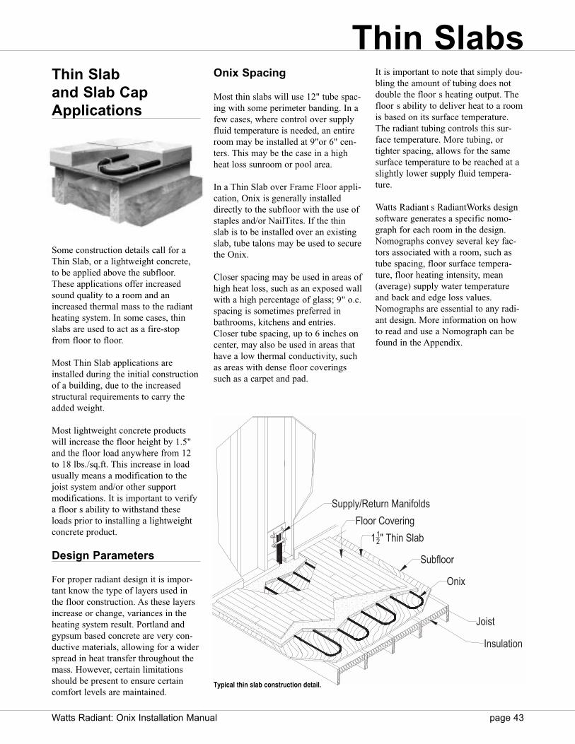
Watts Radiant: Onix Installation Manual page 43
Thin Slab and Slab CapApplications
Some construction details call for aThin Slab, or a lightweight concrete,to be applied above the subfloor.These applications offer increasedsound quality to a room and anincreased thermal mass to the radiantheating system. In some cases, thinslabs are used to act as a fire-stopfrom floor to floor.
Most Thin Slab applications areinstalled during the initial constructionof a building, due to the increasedstructural requirements to carry theadded weight.
Most lightweight concrete productswill increase the floor height by 1.5"and the floor load anywhere from 12to 18 lbs./sq.ft. This increase in loadusually means a modification to thejoist system and/or other support modifications. It is important to verifya floor s ability to withstand theseloads prior to installing a lightweight concrete product.
Design Parameters
For proper radiant design it is impor-tant know the type of layers used inthe floor construction. As these layersincrease or change, variances in theheating system result. Portland andgypsum based concrete are very con-ductive materials, allowing for a widerspread in heat transfer throughout themass. However, certain limitationsshould be present to ensure certaincomfort levels are maintained.
Onix Spacing
Most thin slabs will use 12" tube spac-ing with some perimeter banding. In afew cases, where control over supplyfluid temperature is needed, an entireroom may be installed at 9"or 6" cen-ters. This may be the case in a highheat loss sunroom or pool area.
In a Thin Slab over Frame Floor appli-cation, Onix is generally installeddirectly to the subfloor with the use ofstaples and/or NailTites. If the thinslab is to be installed over an existingslab, tube talons may be used to securethe Onix.
Closer spacing may be used in areas ofhigh heat loss, such as an exposed wallwith a high percentage of glass; 9" o.c.spacing is sometimes preferred inbathrooms, kitchens and entries.Closer tube spacing, up to 6 inches oncenter, may also be used in areas thathave a low thermal conductivity, suchas areas with dense floor coveringssuch as a carpet and pad.
It is important to note that simply dou-bling the amount of tubing does notdouble the floor s heating output. Thefloor s ability to deliver heat to a roomis based on its surface temperature.The radiant tubing controls this sur-face temperature. More tubing, ortighter spacing, allows for the samesurface temperature to be reached at aslightly lower supply fluid tempera-ture.
Watts Radiant s RadiantWorks designsoftware generates a specific nomo-graph for each room in the design.Nomographs convey several key fac-tors associated with a room, such astube spacing, floor surface tempera-ture, floor heating intensity, mean(average) supply water temperatureand back and edge loss values.Nomographs are essential to any radi-ant design. More information on howto read and use a Nomograph can befound in the Appendix.
Supply/Return Manifolds
Floor Covering
112" Thin Slab
Subfloor
Onix
Joist
Insulation
Typical thin slab construction detail.
Thin Slabs
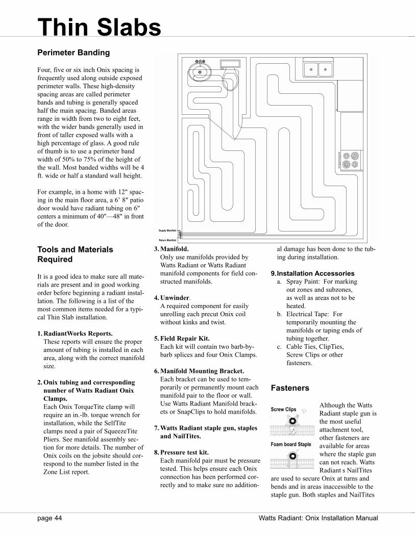
page 44 Watts Radiant: Onix Installation Manual
Perimeter Banding
Four, five or six inch Onix spacing isfrequently used along outside exposedperimeter walls. These high-densityspacing areas are called perimeterbands and tubing is generally spacedhalf the main spacing. Banded areasrange in width from two to eight feet,with the wider bands generally used infront of taller exposed walls with ahigh percentage of glass. A good ruleof thumb is to use a perimeter bandwidth of 50% to 75% of the height ofthe wall. Most banded widths will be 4ft. wide or half a standard wall height.
For example, in a home with 12" spac-ing in the main floor area, a 6’ 8" patiodoor would have radiant tubing on 6"centers a minimum of 40"—48" in frontof the door.
Tools and MaterialsRequired
It is a good idea to make sure all mate-rials are present and in good workingorder before beginning a radiant instal-lation. The following is a list of themost common items needed for a typi-cal Thin Slab installation.
1. RadiantWorks Reports.These reports will ensure the properamount of tubing is installed in eacharea, along with the correct manifoldsize.
2. Onix tubing and correspondingnumber of Watts Radiant OnixClamps.Each Onix TorqueTite clamp willrequire an in.-lb. torque wrench forinstallation, while the SelfTiteclamps need a pair of SqueezeTitePliers. See manifold assembly sec-tion for more details. The number ofOnix coils on the jobsite should cor-respond to the number listed in theZone List report.
3. Manifold.Only use manifolds provided byWatts Radiant or Watts Radiantmanifold components for field con-structed manifolds.
4. Unwinder.A required component for easilyunrolling each precut Onix coilwithout kinks and twist.
5. Field Repair Kit.Each kit will contain two barb-by-barb splices and four Onix Clamps.
6. Manifold Mounting Bracket.Each bracket can be used to tem-porarily or permanently mount eachmanifold pair to the floor or wall.Use Watts Radiant Manifold brack-ets or SnapClips to hold manifolds.
7. Watts Radiant staple gun, staplesand NailTites.
8. Pressure test kit.Each manifold pair must be pressuretested. This helps ensure each Onixconnection has been performed cor-rectly and to make sure no addition-
al damage has been done to the tub-ing during installation.
9.Installation Accessoriesa. Spray Paint: For marking
out zones and subzones, as well as areas not to be heated.
b. Electrical Tape: For temporarily mounting the manifolds or taping ends of tubing together.
c. Cable Ties, ClipTies, Screw Clips or other fasteners.
Fasteners
Although the WattsRadiant staple gun isthe most usefulattachment tool,other fasteners areavailable for areaswhere the staple guncan not reach. WattsRadiant s NailTites
are used to secure Onix at turns andbends and in areas inaccessible to thestaple gun. Both staples and NailTites
Screw Clips
Foam board Staple
Returnrn Manififoldld
Supplyly Manififoldld
Thin Slabs
Supply Manifold
Return Manifold
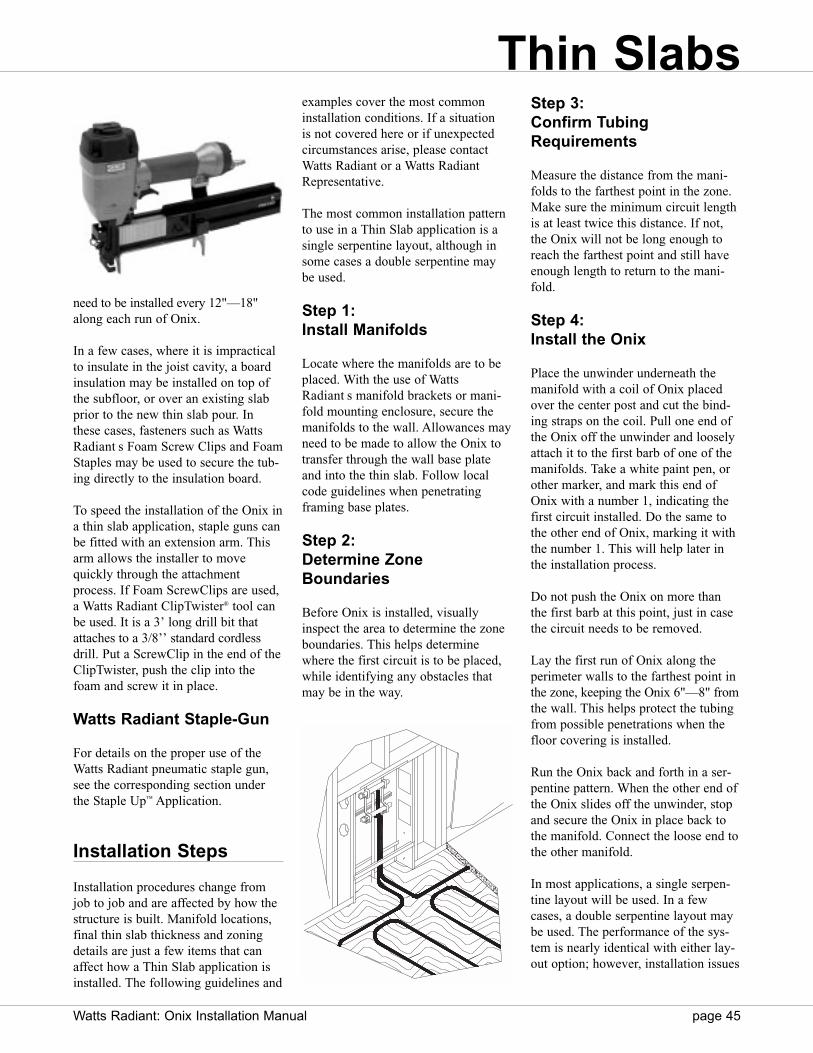
Watts Radiant: Onix Installation Manual page 45
need to be installed every 12"—18"along each run of Onix.
In a few cases, where it is impracticalto insulate in the joist cavity, a boardinsulation may be installed on top ofthe subfloor, or over an existing slabprior to the new thin slab pour. Inthese cases, fasteners such as WattsRadiant s Foam Screw Clips and FoamStaples may be used to secure the tub-ing directly to the insulation board.
To speed the installation of the Onix ina thin slab application, staple guns canbe fitted with an extension arm. Thisarm allows the installer to movequickly through the attachmentprocess. If Foam ScrewClips are used,a Watts Radiant ClipTwister® tool canbe used. It is a 3’ long drill bit thatattaches to a 3/8’’ standard cordlessdrill. Put a ScrewClip in the end of theClipTwister, push the clip into thefoam and screw it in place.
Watts Radiant Staple-Gun
For details on the proper use of theWatts Radiant pneumatic staple gun,see the corresponding section underthe Staple Up™ Application.
Installation Steps
Installation procedures change fromjob to job and are affected by how thestructure is built. Manifold locations,final thin slab thickness and zoningdetails are just a few items that canaffect how a Thin Slab application isinstalled. The following guidelines and
examples cover the most commoninstallation conditions. If a situation is not covered here or if unexpectedcircumstances arise, please contactWatts Radiant or a Watts RadiantRepresentative.
The most common installation patternto use in a Thin Slab application is asingle serpentine layout, although insome cases a double serpentine maybe used.
Step 1: Install Manifolds
Locate where the manifolds are to beplaced. With the use of WattsRadiant s manifold brackets or mani-fold mounting enclosure, secure themanifolds to the wall. Allowances mayneed to be made to allow the Onix totransfer through the wall base plateand into the thin slab. Follow localcode guidelines when penetratingframing base plates.
Step 2: Determine ZoneBoundaries
Before Onix is installed, visuallyinspect the area to determine the zoneboundaries. This helps determinewhere the first circuit is to be placed,while identifying any obstacles thatmay be in the way.
Step 3: Confirm TubingRequirements
Measure the distance from the mani-folds to the farthest point in the zone.Make sure the minimum circuit lengthis at least twice this distance. If not,the Onix will not be long enough toreach the farthest point and still haveenough length to return to the mani-fold.
Step 4: Install the Onix
Place the unwinder underneath themanifold with a coil of Onix placedover the center post and cut the bind-ing straps on the coil. Pull one end ofthe Onix off the unwinder and looselyattach it to the first barb of one of themanifolds. Take a white paint pen, orother marker, and mark this end ofOnix with a number 1, indicating thefirst circuit installed. Do the same tothe other end of Onix, marking it withthe number 1. This will help later inthe installation process.
Do not push the Onix on more thanthe first barb at this point, just in casethe circuit needs to be removed.
Lay the first run of Onix along theperimeter walls to the farthest point inthe zone, keeping the Onix 6"—8" fromthe wall. This helps protect the tubingfrom possible penetrations when thefloor covering is installed.
Run the Onix back and forth in a ser-pentine pattern. When the other end ofthe Onix slides off the unwinder, stopand secure the Onix in place back tothe manifold. Connect the loose end tothe other manifold.
In most applications, a single serpen-tine layout will be used. In a fewcases, a double serpentine layout maybe used. The performance of the sys-tem is nearly identical with either lay-out option; however, installation issues
Thin Slabs
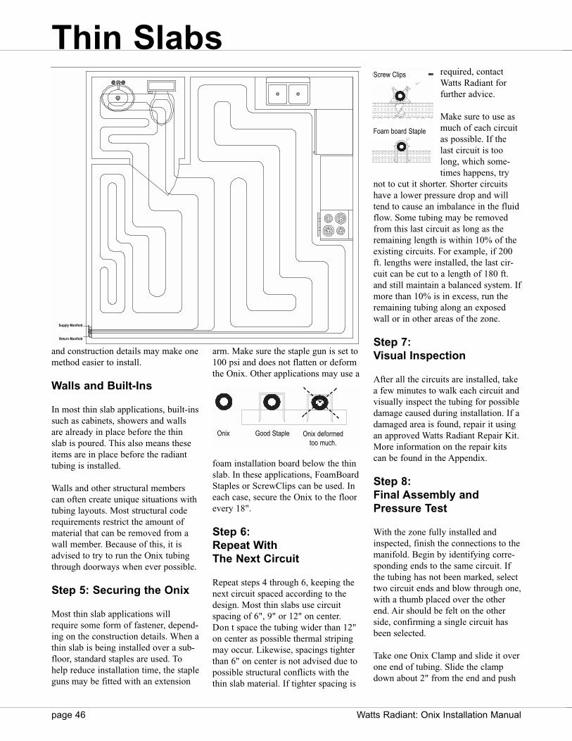
page 46 Watts Radiant: Onix Installation Manual
and construction details may make onemethod easier to install.
Walls and Built-Ins
In most thin slab applications, built-inssuch as cabinets, showers and wallsare already in place before the thinslab is poured. This also means theseitems are in place before the radianttubing is installed.
Walls and other structural memberscan often create unique situations withtubing layouts. Most structural coderequirements restrict the amount ofmaterial that can be removed from awall member. Because of this, it isadvised to try to run the Onix tubingthrough doorways when ever possible.
Step 5: Securing the Onix
Most thin slab applications willrequire some form of fastener, depend-ing on the construction details. When athin slab is being installed over a sub-floor, standard staples are used. Tohelp reduce installation time, the stapleguns may be fitted with an extension
arm. Make sure the staple gun is set to100 psi and does not flatten or deformthe Onix. Other applications may use a
foam installation board below the thinslab. In these applications, FoamBoardStaples or ScrewClips can be used. Ineach case, secure the Onix to the floorevery 18".
Step 6: Repeat With The Next Circuit
Repeat steps 4 through 6, keeping thenext circuit spaced according to thedesign. Most thin slabs use circuitspacing of 6", 9" or 12" on center.Don t space the tubing wider than 12"on center as possible thermal stripingmay occur. Likewise, spacings tighterthan 6" on center is not advised due topossible structural conflicts with thethin slab material. If tighter spacing is
required, contactWatts Radiant forfurther advice.
Make sure to use asmuch of each circuitas possible. If thelast circuit is toolong, which some-times happens, try
not to cut it shorter. Shorter circuitshave a lower pressure drop and willtend to cause an imbalance in the fluidflow. Some tubing may be removedfrom this last circuit as long as theremaining length is within 10% of theexisting circuits. For example, if 200ft. lengths were installed, the last cir-cuit can be cut to a length of 180 ft.and still maintain a balanced system. Ifmore than 10% is in excess, run theremaining tubing along an exposedwall or in other areas of the zone.
Step 7: Visual Inspection
After all the circuits are installed, takea few minutes to walk each circuit andvisually inspect the tubing for possibledamage caused during installation. If adamaged area is found, repair it usingan approved Watts Radiant Repair Kit.More information on the repair kitscan be found in the Appendix.
Step 8: Final Assembly andPressure Test
With the zone fully installed andinspected, finish the connections to themanifold. Begin by identifying corre-sponding ends to the same circuit. Ifthe tubing has not been marked, selecttwo circuit ends and blow through one,with a thumb placed over the otherend. Air should be felt on the otherside, confirming a single circuit hasbeen selected.
Take one Onix Clamp and slide it overone end of tubing. Slide the clampdown about 2" from the end and push
Screw Clips
Foam board Staple
Returnrn Manififoldld
Supplyly Manififoldld
Good Staple Onix deformed too much.
Onix
Thin Slabs
Supply Manifold
Return Manifold
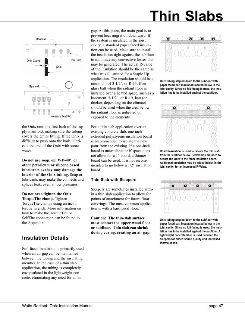
Watts Radiant: Onix Installation Manual page 47
the Onix onto the first barb of the sup-ply manifold, making sure the tubingcovers the entire fitting. If the Onix isdifficult to push onto the barb, lubri-cate the end of the Onix with somewater.
Do not use soap, oil, WD-40®, orother petroleum or silicone basedlubricants as they may damage theinterior of the Onix tubing. Soap orlubricants may make the connects andsplices leak, even at low pressures.
Do not over-tighten the OnixTorqueTite clamp. TightenTorqueTite clamps using an in.-lb.torque wrench. More information onhow to make the TorqueTite orSelfTite connection can be found inthe Appendix.
Insulation Details
Foil-faced insulation is primarily usedwhen an air gap can be maintainedbetween the tubing and the insulatingmember. In the case of a thin slabapplication, the tubing is completelyencapsulated in the lightweight con-crete, eliminating any need for an air
gap. At this point, the main goal is toprevent heat migration downward. Ifthe system is insulated in the joist cavity, a standard paper faced insula-tion can be used. Make sure to installthe insulation tight against the subfloorto minimize any convective losses thatmay be generated. The actual R-valueof the insulation should be the same aswhat was illustrated for a Staple Upapplication. The insulation should be aminimum of 3-1/2", or R-13, fiber-glass batt when the radiant floor isinstalled over a heated space, such as abasement. 5-1/2", or R-19, batt (orthicker, depending on the climate)should be used when the area belowthe radiant floor is unheated orexposed to the elements.
For a thin slab application over anexisting concrete slab, one inchextruded polystyrene insulation boardis recommended to isolate the newpour from the existing. If a one-inchboard is unavailable or if space doesnot allow for a 1" board, a thinnerboard can be used. It is not recom-mended to go below a 1/2" insulationboard.
Thin Slab with Sleepers
Sleepers are sometimes installed with-in a thin slab application to allow forpoints of attachment for future floorcoverings. The most common applica-tion is with a hardwood floor.
Caution: The thin-slab surfacemust contact the upper wood flooror subfloor. Thin slab can shrinkduring curing, creating an air gap.
Manifold
Onix BarbOnix Clamp
Onix
Manifold
Pressure Test Kit
Onix tubing stapled down to the subfloor withpaper faced batt insulation located below in thejoist cavity. Since no foil facing is used, the insu-lation has to be installed against the subfloor.
Board insulation is used to isolate the thin slabfrom the subfloor below. ScrewClips are used tosecure the Onix to the foam insulation board.Additional insulation may be added below, in thejoist cavity, for an increased R-Value.
Onix tubing stapled down to the subfloor withpaper faced batt insulation located below in thejoist cavity. Since no foil facing is used, the insu-lation has to be installed against the subfloor. Alightweight concrete filler is used between thesleepers for added sound quality and increasedthermal mass.
Thin Slabs

Commercial applications require spe-cial design considerations and flexibil-ity. This is especially true whendesigning and installing a radiant floorover a steel deck or precast concretefloor.
Steel Deck
Steel decks are usually seen in officemezzanines and other areas that willexperience light to moderate loads.There are several different types ofsteel decks, ranging from 2’’ anglechannels to 6’’ square channels. Thesechannels will play a part in determin-ing what Onix spacing should be used.
When possible, install the Onix per-pendicular to the ribbing on the steeldeck. There is only one area a steeldeck application can be insulated, thatbeing under the steel deck. In this con-figuration, it is almost impossible toinsulated under a steel deck systemwith batt insulation, since the supportmembers tend to be farther apart thanthe typical 16’’ o.c.
In most slabs, rewire or rebar will beused, giving the installer a way tosecure the Onix. In some applicationsfiberglass mesh will be used instead ofrewire/rebar. In this case Railwaysmay be used.
Precast Slabs
Precast slabs are similar to a steel deckapplication with the exception of themain support layer. The precast slab isdesigned, in most cases to be the floorsupport of the level above and the fin-ished ceiling for the level below.Because of this it is difficult to insu-late a precast slab system. Insulationoptions need to be discussed with theproject engineer or architect.
Likewise, rewire/rebar may or may notbe used in the cap pour. Fastenertypes are chosen based on theapproved construction requirements.
page 48 Watts Radiant: Onix Installation Manual
Steel Decks
Rewire/Rebar
RailwayCable Tie ClipTie
Various tube fasteners for steel deck slab applications.
Concrete
Steel Deck
Insulation
Electrical Chase Onix Rewire/Rebar
Concrete Cap
Precast Concrete
Electrical ChaseOnix
Typical Slab over Steel Deck application. Insulation board is usually installed below the steel deck,minimum 1” thick.
Typical Slab over Precast application. Insulation location and fasteners are variables depending onthe structural requirements of the total mass. Consult with the structural engineer before choosingan insulation or fastening method.
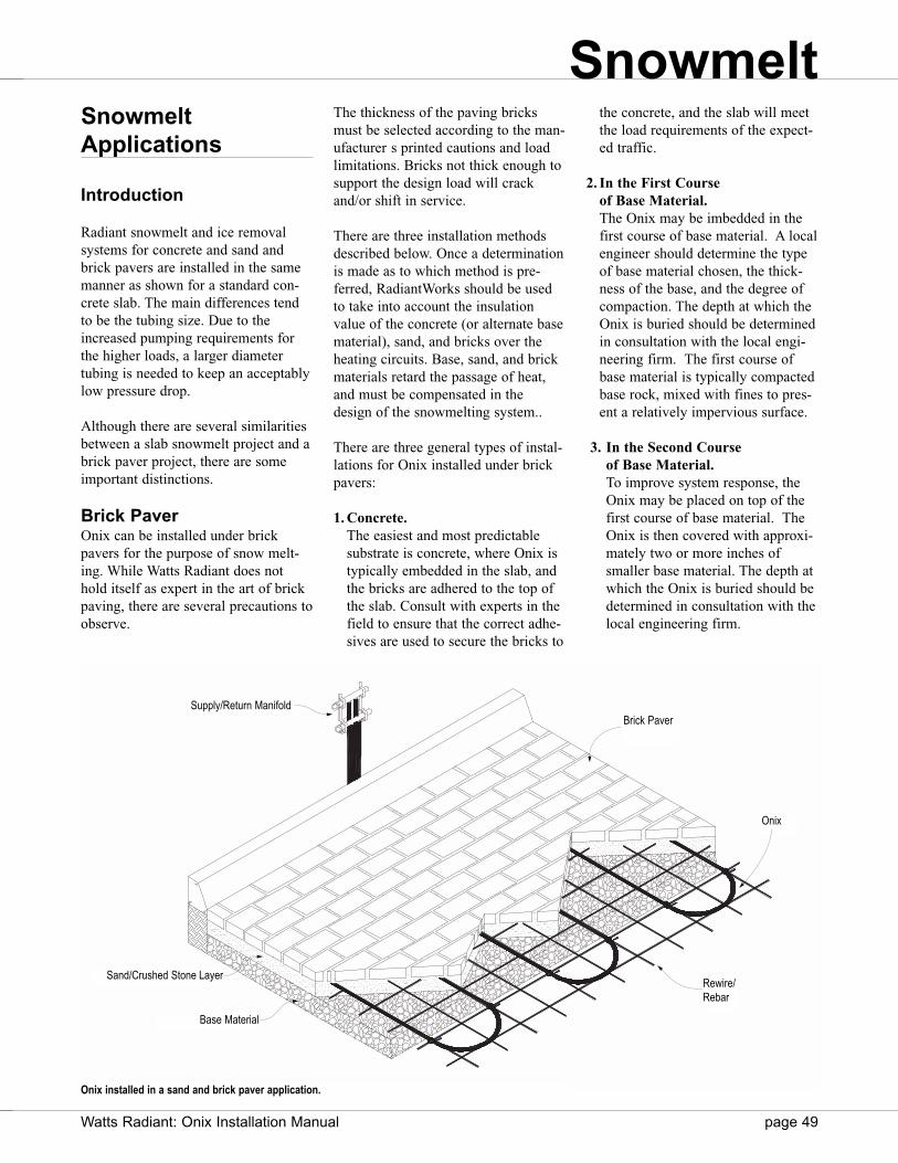
SnowmeltApplications
Introduction
Radiant snowmelt and ice removalsystems for concrete and sand andbrick pavers are installed in the samemanner as shown for a standard con-crete slab. The main differences tendto be the tubing size. Due to theincreased pumping requirements forthe higher loads, a larger diameter tubing is needed to keep an acceptablylow pressure drop.
Although there are several similaritiesbetween a slab snowmelt project and abrick paver project, there are someimportant distinctions.
Brick PaverOnix can be installed under brickpavers for the purpose of snow melt-ing. While Watts Radiant does nothold itself as expert in the art of brickpaving, there are several precautions toobserve.
The thickness of the paving bricksmust be selected according to the man-ufacturer s printed cautions and loadlimitations. Bricks not thick enough tosupport the design load will crackand/or shift in service.
There are three installation methodsdescribed below. Once a determinationis made as to which method is pre-ferred, RadiantWorks should be usedto take into account the insulationvalue of the concrete (or alternate basematerial), sand, and bricks over theheating circuits. Base, sand, and brickmaterials retard the passage of heat,and must be compensated in thedesign of the snowmelting system..
There are three general types of instal-lations for Onix installed under brickpavers:
1. Concrete.The easiest and most predictablesubstrate is concrete, where Onix istypically embedded in the slab, andthe bricks are adhered to the top ofthe slab. Consult with experts in thefield to ensure that the correct adhe-sives are used to secure the bricks to
the concrete, and the slab will meetthe load requirements of the expect-ed traffic.
2. In the First Course of Base Material.The Onix may be imbedded in thefirst course of base material. A localengineer should determine the typeof base material chosen, the thick-ness of the base, and the degree ofcompaction. The depth at which theOnix is buried should be determinedin consultation with the local engi-neering firm. The first course ofbase material is typically compactedbase rock, mixed with fines to pres-ent a relatively impervious surface.
3. In the Second Course of Base Material.To improve system response, theOnix may be placed on top of thefirst course of base material. TheOnix is then covered with approxi-mately two or more inches ofsmaller base material. The depth atwhich the Onix is buried should bedetermined in consultation with thelocal engineering firm.
Snowmelt
Onix installed in a sand and brick paver application.
Watts Radiant: Onix Installation Manual page 49
Rewire/Rebar
Onix
Brick PaverSupply/Return Manifold
Base Material
Sand/Crushed Stone Layer
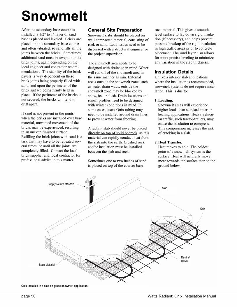
page 50 Watts Radiant: Onix Installation Manual
After the secondary base course isinstalled, a 1/2" to 1" layer of sandbase is placed and leveled. Bricks areplaced on this secondary base courseand often vibrated, so sand fills all thejoints between the bricks. Sometimesadditional sand must be swept into thebrick joints, again depending on thelocal engineer and contractor recom-mendations. The stability of the brickpavers is very dependent on thesebrick joints being properly filled withsand, and upon the perimeter of thebrick surface being firmly held inplace. If the perimeter of the bricks isnot secured, the bricks will tend todrift apart.
If sand is not present in the jointswhen the bricks are installed over basematerial, unwanted movement of thebricks may be experienced, resultingin an uneven finished surface.Refilling the brick joints with sand is atask that may have to be repeated sev-eral times, or until all the joints arecompletely filled. Contact the localbrick supplier and local contractor forprofessional advice in this matter.
General Site PreparationSnowmelt slabs should be placed onwell compacted material, consisting ofrock or sand. Load issues need to bediscussed with a structural engineer orthe project supervisor.
The snowmelt area needs to bedesigned with drainage in mind. Waterwill run off of the snowmelt area inthe same manner as rain. Externalareas outside the snowmelt zone, suchas water drain ways, outside thesnowmelt zone may be blocked bysnow, ice or slush. Drain locations andrunoff profiles need to be designedwith winter conditions in mind. Insome cases, extra Onix tubing mayneed to be installed around drain linesto prevent water from freezing.
A radiant slab should never be placeddirectly on top of solid bedrock, as thismaterial can rapidly conduct heat fromthe slab into the earth. Crushed rockand/or insulation must be installedbetween the slab and rock.
Sometimes one to two inches of sandis placed on top of the coarser base
rock material. This gives a smooth,level surface to lay down rigid insula-tion (if necessary), and helps preventpossible breakup of the rigid insulationin high traffic areas prior to concreteplacement. The sand layer also allowsfor more precise leveling to minimizeany variation in the slab thickness.
Insulation DetailsUnlike a interior slab applicationswhere the insulation is recommended,snowmelt systems do not require insu-lation. This is due to:
1. Loading.Snowmelt areas will experiencehigher loads than standard interiorheating applications. Heavy vehicu-lar traffic, such tractor-trailers, maycause the insulation to compress.This compression increases the riskof cracking in a slab.
2. Heat Transfer.Heat moves to cold. The coldestpoint of a snowmelt system is thesurface. Heat will naturally movemore towards the surface than to theground below.
Onix installed in a slab on grade snowmelt application.
Snowmelt
Rewire/Rebar
Onix
SlabSupply/Return Manifold
Base Material
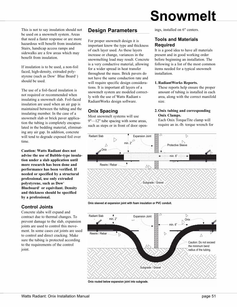
This is not to say insulation should notbe used on a snowmelt system. Areasthat need a faster response or are morehazardous will benefit from insulation.Stairs, handicap access ramps andsidewalks are a few areas which maybenefit from insulation.
If insulation is to be used, a non-foilfaced, high-density, extruded poly-styrene (such as Dow¤ Blue Board¤ )should be used.
The use of a foil-faced insulation isnot required or recommended wheninsulating a snowmelt slab. Foil-facedinsulation are used when an air gap ismaintained between the tubing and theinsulating member. In the case of asnowmelt slab or brick paver applica-tion the tubing is completely encapsu-lated in the bedding material, eliminat-ing any air gap. In addition, concretewill tend to degrade exposed foil overtime.
Caution: Watts Radiant does notadvise the use of Bubble-type insula-tion under a slab application untilmore research has been done andperformance has been verified. Ifneeded or specified by a structuralprofessional, use only extruded polystyrene, such as Dow¤
Blueboard¤ or equivilant. Densityand thickness should be specified by a professional.
Control JointsConcrete slabs will expand and contract due to thermal changes. Toprevent damage to the slab, expansionjoints are used to control this move-ment. In some cases cut joints are usedto control and direct cracking. Makesure the tubing is protected accordingto the requirements of the controljoint.
Design Parameters
For proper snowmelt design it isimportant know the type and thicknessof each layer used. As these layersincrease or change, variances in thesnowmelting load may result. Concreteis a very conductive material, allowingfor a wider spread in heat transferthroughout the mass. Brick pavers donot have the same conduction rate andwill require specific design considera-tions. It is important all layers of asnowmelt system are modeled correct-ly with the use of Watts Radiant sRadiantWorks design software.
Onix SpacingMost snowmelt systems will use9"—12" tube spacing with some areas,such as steps or in front of door open-
ings, installed on 6" centers.
Tools and MaterialsRequiredIt is a good idea to have all materialspresent and in good working orderbefore beginning an installation. Thefollowing is a list of the most commonitems needed for a typical snowmeltinstallation.
1. RadiantWorks Reports.These reports help ensure the properamount of tubing is installed in eacharea, along with the correct manifoldsize.
2. Onix tubing and correspondingOnix Clamps.Each Onix TorqueTite clamp willrequire an in.-lb. torque wrench for
Onix routed below expansion joint into subgrade.
Radiant Slab
Radiant Slab
Expansion Joint
Onix
Rewire / Rebar
Protective Sleeve
Subgrade / Gravel
Expansion JointOnix
Rewire / Rebar
Subgrade / Gravel
Onix sleeved at expansion joint with foam insulation or PVC conduit.
min. 6”
min. 2”
Caution: Do not exceedthe minimum bendradius of the tubing.
min. 2”
min. 6”
Snowmelt
Watts Radiant: Onix Installation Manual page 51

page 52 Watts Radiant: Onix Installation Manual
installation, while the SelfTiteclamps need a pair of SqueezeTitePliers. See manifold assembly sec-tion for more details. The number ofOnix coils on the jobsite should cor-respond to the number listed in theZone List report.
3. ManifoldsOnly use Watts Radiant manifolds ormanifold components for field-con-structed manifolds.
4. Unwinder.A required component for easilyunrolling each precut Onix coilwithout kinks and twist.
5. Field Repair Kit.Each kit will contain two barb-by-barb splices and four Onix Clamps.
6. Manifold Mounting Bracket.Each bracket can be used to temporarily or permanently mounteach manifold pair to the floor orwall. Use either Watts Radiantbrackets or SnapClips to hold mani-folds.
7. Watts Radiant staple gun, staplesand NailTites.
8. Pressure test kit.Each manifold pair must be pressuretested. This helps ensure each Onixconnection has been performed cor-rectly and to make sure no damagehas been done to the tubing duringinstallation.
9. Installation Accessoriesa. Electrical Tape for
temporarily mounting the manifolds or taping ends of tubing together.
b. Cable Ties, ClipTies, Screw Clips or other fasteners.
Since rewire/rebar is commonly usedin concrete slabs for structural integri-ty, it is a good practice to attach Onixto the rewire/rebar. This is done withnylon cable ties or Watts RadiantClipTies and Clipper tool. Each willsecure the Onix to the rewire/rebar insuch a way to prevent movement ofthe tubing during the concrete pour.
In applications where rewire/rebar isnot used or an insulation board isplaced underneath the slab, some addi-tional attachment devices can be usedto secure the Onix. RailWays™ can beattached to subgrade with the use ofground stakes or talons. WattsRadiant s Foam Staples or Foam Clipscan be used to secure the Onix tubingdirectly to the insulation board.
Onix ClipTie Rewire or RebarSlab
Subgrade / Compacted Earth
Typical Snowmelt Slab on Grade with Cable Ties.
Onix
Rewire or Rebar
Slab
Subgrade / Compacted Earth
RailWay
Typical Snowmelt Slab on Grade with RailWays.
Onix with Cable Ties
Brick Paver
Subgrade / Compacted Earth
Typical Snowmelt Brick Paver with Cable ties.
Sand/Stone Dust
Snowmelt
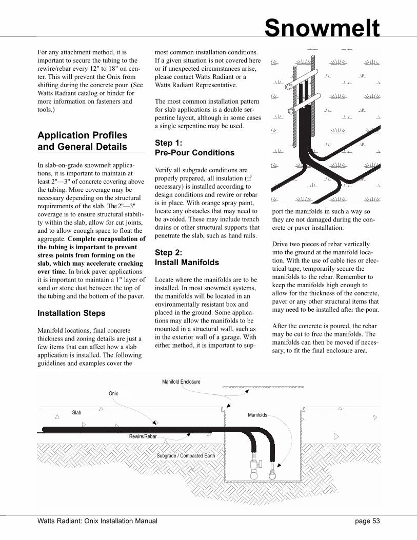
For any attachment method, it isimportant to secure the tubing to therewire/rebar every 12" to 18" on cen-ter. This will prevent the Onix fromshifting during the concrete pour. (SeeWatts Radiant catalog or binder formore information on fasteners andtools.)
Application Profilesand General Details
In slab-on-grade snowmelt applica-tions, it is important to maintain atleast 2"—3" of concrete covering abovethe tubing. More coverage may benecessary depending on the structuralrequirements of the slab. The 2"—3"coverage is to ensure structural stabili-ty within the slab, allow for cut joints,and to allow enough space to float theaggregate. Complete encapsulation ofthe tubing is important to preventstress points from forming on theslab, which may accelerate crackingover time. In brick paver applicationsit is important to maintain a 1" layer ofsand or stone dust between the top ofthe tubing and the bottom of the paver.
Installation Steps
Manifold locations, final concretethickness and zoning details are just afew items that can affect how a slabapplication is installed. The followingguidelines and examples cover the
most common installation conditions.If a given situation is not covered hereor if unexpected circumstances arise,please contact Watts Radiant or aWatts Radiant Representative.
The most common installation patternfor slab applications is a double ser-pentine layout, although in some casesa single serpentine may be used.
Step 1: Pre-Pour Conditions
Verify all subgrade conditions areproperly prepared, all insulation (ifnecessary) is installed according todesign conditions and rewire or rebaris in place. With orange spray paint,locate any obstacles that may need tobe avoided. These may include trenchdrains or other structural supports thatpenetrate the slab, such as hand rails.
Step 2: Install Manifolds
Locate where the manifolds are to beinstalled. In most snowmelt systems,the manifolds will be located in anenvironmentally resistant box andplaced in the ground. Some applica-tions may allow the manifolds to bemounted in a structural wall, such asin the exterior wall of a garage. Witheither method, it is important to sup-
port the manifolds in such a way sothey are not damaged during the con-crete or paver installation.
Drive two pieces of rebar verticallyinto the ground at the manifold loca-tion. With the use of cable ties or elec-trical tape, temporarily secure themanifolds to the rebar. Remember tokeep the manifolds high enough toallow for the thickness of the concrete,paver or any other structural items thatmay need to be installed after the pour.
After the concrete is poured, the rebarmay be cut to free the manifolds. Themanifolds can then be moved if neces-sary, to fit the final enclosure area.
Manifold Enclosure
Onix
Slab
Rewire/Rebar
Manifolds
Subgrade / Compacted Earth
Snowmelt
Watts Radiant: Onix Installation Manual page 53

page 54 Watts Radiant: Onix Installation Manual
Make sure to leave plenty of slack inall Onix circuits (2–5 ft. is recom-mended). A Watts Radiant manifoldbox can be used to secure the mani-folds within a structural wall. WattsRadiant SnapClips and StrapDownscan be used to organize Onix comingfrom the floor and into the protectiveenclosure.
Step 3: Determine ZoneBoundaries
Before Onix is installed, visuallyinspect the area to determine the zoneboundaries. This helps determinewhere the first circuit is to be placed,while identifying any obstacles thatmay be in the way.
Step 4: Confirm TubingRequirements
Measure the distance from the mani-folds to the farthest point in the zone.Make the minimum circuit length is atleast twice this distance. If not, theOnix will not be long enough to reachthe farthest point and still have enoughlength to return to the manifold.
Step 5: Install the Onix
Place the unwinder next to the mani-fold with a coil of Onix placed overthe center post and cut the bindingstraps on the coil. Pull one end of theOnix off the unwinder until the entirecoil is unwound. Loop the coil so thetwo ends meet back together, forminga loop. Loosely attach both ends of thecoil to the manifolds, one to the supplyand one to the return manifold. Take awhite paint pen, or other marker, andmark each end of Onix with a number1, indicating the first circuit installed.This will help later in the installationprocess.
Secure manifolds torebar or other support
Unwind the Onix to form aloop and attach ends to themanifolds
Lay Onix across slab area,keeping tubing spaced todesign conditions.
Secure Onix every 12 to18'' on center to therewire or rebar.
Typical slab snowmelt installation. Onix is installed using a double serpentine pattern.
Snowmelt
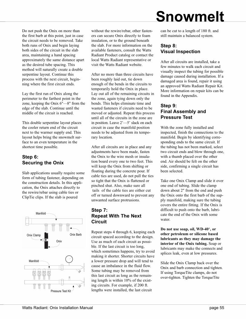
Do not push the Onix on more thanthe first barb at this point, just in casethe circuit needs to be removed. Takeboth runs of Onix and begin layingboth sides of the circuit in the slabarea, maintaining a hand spacingapproximately the same distance apartas the desired tube spacing. Thismethod will naturally create a doubleserpentine layout. Continue thisprocess with the next circuit, begin-ning where the first circuit ends.
Lay the first run of Onix along theperimeter to the farthest point in thezone, keeping the Onix 6"—8" from theedge of the slab. Continue until themiddle of the circuit is reached.
This double serpentine layout placesthe cooler return end of the circuitnext to the warmer supply end. Thislayout helps bring the snowmelt sur-face to an even temperature in theshortest time possible.
Step 6: Securing the Onix
Slab applications usually require someform of tubing fastener, depending onthe construction details. In this appli-cation, the Onix attaches directly tothe rewire/rebar using cable ties orClipTie clips. If the slab is poured
without the rewire/rebar, other fasten-ers can secure Onix directly to foaminsulation, or to the ground beneaththe slab. For more information on theavailable fasteners, consult the WattsRadiant Product catalog or contact thelocal Watts Radiant representative orvisit the Watts Radiant website.
After no more than three circuits havebeen roughly laid out, tie downenough of the bends in the circuits totemporarily hold the Onix in place.Lay out all of the remaining circuits inthe zone, again tying down only thebends. This helps eliminate time andwasted fasteners if circuits need to bemoved or adjusted. Repeat this processuntil all of the circuits in the zone arein position. Leave 2’—5’ slack on eachcircuit in case the manifold positionneeds to be adjusted from its tempo-rary location.
After all circuits are in place and anyadjustments have been made, fastenthe Onix to the wire mesh or insula-tion board every one to two feet. Thiswill keep the Onix from shifting orfloating during the concrete pour. Ifcable ties are used, do not pull the tiesso tight that the Onix is flattened orpinched shut. Also, make sure alltails of the cable ties are either cut
off or turned downward to prevent anyunwanted surface protrusions.
Step 7: Repeat With The NextCircuit
Repeat steps 4 through 6, keeping eachcircuit spaced according to the design.Use as much of each circuit as possi-ble. If the last circuit is too long,which sometimes happens, try to avoidmaking it shorter. Shorter circuits havea lower pressure drop and will tend tocause an imbalance in the fluid flow.Some tubing may be removed fromthis last circuit as long as the remain-ing length is within 10% of the exist-ing circuits. For example, if 200 ft.lengths were installed, the last circuit
can be cut to a length of 180 ft. andstill maintain a balanced system.
Step 8: Visual Inspection
After all circuits are installed, take afew minutes to walk each circuit andvisually inspect the tubing for possibledamage caused during installation. If adamaged area is found, repair it usingan approved Watts Radiant Repair Kit.More information on repair kits can befound in the Appendix.
Step 9: Final Assembly andPressure Test
With the zone fully installed andinspected, finish the connections to themanifold. Begin by identifying corre-sponding ends to the same circuit. Ifthe tubing has not been marked, selecttwo circuit ends and blow through one,with a thumb placed over the otherend. Air should be felt on the otherside, confirming a single circuit hasbeen selected.
Take one Onix Clamp and slide it overone end of tubing. Slide the clampdown about 2" from the end and pushthe Onix onto the first barb of the sup-ply manifold, making sure the tubingcovers the entire fitting. If the Onix isdifficult to push onto the barb, lubri-cate the end of the Onix with somewater.
Do not use soap, oil, WD-40®, orother petroleum or silicone basedlubricants as they may damage theinterior of the Onix tubing. Soap orlubricants may make the connects andsplices leak, even at low pressures.
Slide the Onix Clamp back over theOnix and barb connection and tighten.If using TorqueTite clamps, do notover-tighten. Tighten the TorqueTite
Manifold
Onix BarbOnix Clamp
Onix
Manifold
Pressure Test Kit
Snowmelt
Watts Radiant: Onix Installation Manual page 55
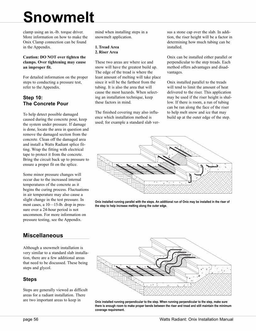
page 56 Watts Radiant: Onix Installation Manual
clamp using an in.-lb. torque driver.More information on how to make theOnix Clamp connection can be foundin the Appendix.
Caution: DO NOT over tighten theclamps. Over tightening may causean improper fit.
For detailed information on the propersteps to conducting a pressure test,refer to the Appendix.
Step 10: The Concrete Pour
To help detect possible damagedcaused during the concrete pour, keepthe system under pressure. If damageis done, locate the area in question andremove the damaged section from theconcrete. Clean off the damaged areaand install a Watts Radiant splice fit-ting. Wrap the fitting with electricaltape to protect it from the concrete.Bring the circuit back up to pressure toensure a proper fit on the splice.
Some minor pressure changes willoccur due to the increased internaltemperatures of the concrete as itbegins the curing process. Fluctuationsin air temperature may also cause aslight change in the test pressure. Inmost cases, a 10—15-lb. drop in pres-sure over a 24-hour period is notuncommon. For more information onpressure testing, see the Appendix.
Miscellaneous
Although a snowmelt installation isvery similar to a standard slab installa-tion, there are a few additional areasthat need to be discussed. These beingsteps and glycol.
Steps
Steps are generally viewed as difficultareas for a radiant installation. Thereare two important areas to keep in
mind when installing steps in asnowmelt application.
1. Tread Area2. Riser Area
These two areas are where ice andsnow will have the greatest build up.The edge of the tread is where theleast amount of melting will take placesince it will be the farthest from thetubing. It is also the area that willcause the most hazards. When select-ing an installation technique, keepthese factors in mind.
The finished covering may also influ-ence which installation method isused; for example a standard slab ver-
sus a stone cap over the slab. In addi-tion, the riser height will be a factor indetermining how much tubing can beinstalled.
Onix can be installed either parallel orperpendicular to the step treads. Eachmethod offers advantages and disad-vantages.
Onix installed parallel to the treadswill tend to limit the amount of heatdelivered to the riser. This applicationmay be used if the riser height is shal-low. If there is room, a run of tubingcan be ran along the face of the riserto help melt snow and ice that maybuild up at the outer edge of the step.
Onix installed running parallel with the steps. An additional run of Onix may be installed in the riser ofthe step to help increase melting along the outer edge.
Onix installed running perpendicular to the step. When running perpendicular to the step, make surethere is enough room to make proper bends between the riser and tread and still maintain the minimumcoverage requirement.
Snowmelt

Systems should not be operated at lev-els below 30% glycol. Glycol levelsbelow 25% do not contain enough cor-rosion inhibitors and may cause theglycol to act as food, allowingmicrobes to grow. The microbes feed,grow and die, allowing a black sludgematerial to form in the system.Concentrations above 25%, propyleneglycol prevents microbe growth. Trynot to exceed a mixture level greaterthan 70% as the fluid may become tooviscous (thick) for the circulators.
As glycol in the system ages, theinhibitors and buffers added to the sys-tem begin to break down. This processslowly returns the system to the natu-ral pH level of the glycol. If not prop-erly maintained, glycol in the systemcan cause corrosion. Check a glycolsystem at least once a year to ensurethe glycol is still within its operatingparameters.
Glycol Maintenance
A glycol system should be checked fortwo things: system pH and freeze pro-tection. The quickest way to check aglycol system s pH is with litmuspaper. If the pH drops below 7, thenmore buffers must be added to a sys-tem or the system needs to be flushedand refilled. There are only a limitednumber of times buffers can be addedto a system before it must be flushedand replaced. Check with the glycolmanufacturer for further details. Someglycol manufacturers will require ahigher minimum pH to be maintained.
Freeze Protection
The second item that must be checkedin a glycol system is the actual level offreeze protection provided. WattsRadiant recommends a 50% glycolsolution. However, this does notalways equate to a 50% glycol solu-tion and 50% water. Different glycolproviders supply different concentra-tions of glycol and/or may mix a cer-tain amount of distilled water with theinhibitors. For example, a glycol thatis already pre-mixed to a 50% leveland then is diluted by the installer with50/50 water have a true 25% glycolconcentration.
The only way to accurately measureglycol in a system is to use a refrac-tometer. A refractometer uses a simpleproperty of a liquid to determine itsfreeze point. Liquid will refract, orbend light at a known angle. Thisangle is a direct correlation to itsfreeze point. A refractometer is adevice that measures this deflection. Abasic refractometer is a device thatlooks like a kaleidoscope. The userplaces a drop of fluid on a lens on oneend and then looks through the otherend. What is seen is a chart that showsthe freeze point.
This should be checked before andafter the glycol is installed. Check asample mixture, one cup glycol andone cup water. Test this solution withthe refractometer to see what the sys-tem freeze protection will be. Do thiseach time the system is re-filled withnew glycol. Also, check the freezeprotection when the system pH ischecked just to make sure the systemis operating within the desired parame-ters.
Caution: The refractometer usedmust be calibrated for propyleneglycol. A refractometer calibratedfor automotive (ethylene) glycol willnot yield accurate results.
Perpendicular installations may be eas-ier to install on long narrow steps.This approach will more easily meltsnow and ice that may build up alongthe outer step edge. However, it mayrequire additional rebar to support thetubing around bends as it moves fromstep to step.
In both applications it is important tokeep the Onix 2"—3’’ away from thesurface of the concrete. In some casesit may be ideal to install a designatedmanifold for the steps. This allows fora dedicated vent/purge assembly to beused for purging the tubing located inthe steps.
Glycol
Any hydronic system that is exposedto near or below freezing conditionsmust have propylene glycol installedas the working fluid. Propylene glycolcan prevent the system fluid fromfreezing. The level of frost protectionwill depend on the glycol concentra-tion used.
Glycol Basics
Glycol is naturally corrosive. Buffersand inhibitors are added to offset thiscorrosive effect. In addition, glycolacts like an oxygen grabber , absorb-ing any free oxygen molecules in thesystem. The more oxygen the glycolgrabs , the more acidic it will
become.
1010
0
-10
-20
-30
-40
Typical Refractometer image as seenthrough the view finder. The terminus linebetween the shaded area and the lightarea represents the freeze level of the fluidin question. In this case, the fluid beingtested is freeze protected to –15°F.
Snowmelt
Watts Radiant: Onix Installation Manual page 57

page 58 Watts Radiant: Onix Installation Manual
Manifolds
Copper and BrassManifolds
Manifolds are used to transition fromsupply/return piping to Onix. Mani-folds are usually copper or brass bod-ies, with brass branches attached to the sides.
Factory Supplied Manifolds
A variety of pre-manufactured mani-fold options are available from WattsRadiant, each specifically designed tomeet or exceed any job specification.
Among the various options are:Custom Tubular (Copper and Brass)
Custom Tubular Manifolds arecustom fabricated to each pro-ject s specifications with anynumber of circuits in diametersfrom 1" to 6".
CazzBrassCazzBrass Manifolds are con-structed of cast brass and comein either 3 or 4 circuits and cou-ple directly to each other to formlarger manifold sets. CazzBrassmanifolds come with the follow-ing options: blank, with flowmeters, or with balancing valves.
Stainless SteelStainless steel Manifolds areconstructed of tubular stainlesssteel and range from 2 to 12 cir-cuits. Each pair comes with flowmeters, circuit balancing valvesand mounted brackets.
CustomCut (copper)CustomCut manifolds are pre-made manifolds that come with12 or 16 barbs. CustomCut man-ifolds are then cut in the field tothe specific circuit number need-ed for each zone.
Swedged (copper)Swedged manifolds are pre-mademanifolds with 3, 4, or 5 circuits.One end of a Swedged manifold
is flared so it can directly coupleto another Swedged manifold.For example, a 3- and a 4-branchSwedged manifold can be fieldcoupled to form one 7-branchmanifold assembly.
For more information on the variousmanifold options see our RadiantCatalog, or visit us on the Web atwww.wattsradiant.com.
Field ConstructedManifolds
Some installers prefer to build theirown manifolds on the jobsite. Coppermanifolds can be made of any sizecopper water pipe tubing. Manifoldsfrom Watts Radiant are made of type Lcopper for standard use, and if request-ed, type K copper for undergroundexternal applications.
Caution: Use only Watts Radiant Parts.
Do not use clamps or Onix Barbs notsupplied by Watts Radiant.
Connections made with barbs orclamps supplied by other companiesare specifically excluded from anyWatts Radiant warranty coverage.
There are three main ways to fieldconstruct a manifold.
1. CustomCut Manifolds: Manifold sticks from the factorydesigned to be used with any Onixbarb. Installers can purchase prefab-ricated CustomCuts or base branchmanifolds and field solder variouscombinations of barbs and mini-ballvalves as the job demands.
Supply Manifold
Return Manifold
Onix Barb
End Cap or Plug
Onix Barb
Mini Ball Valve
Fluid Flow
Fluid Flow
Typical Copper or Tubular Brass Manifold Pair.
Appendix
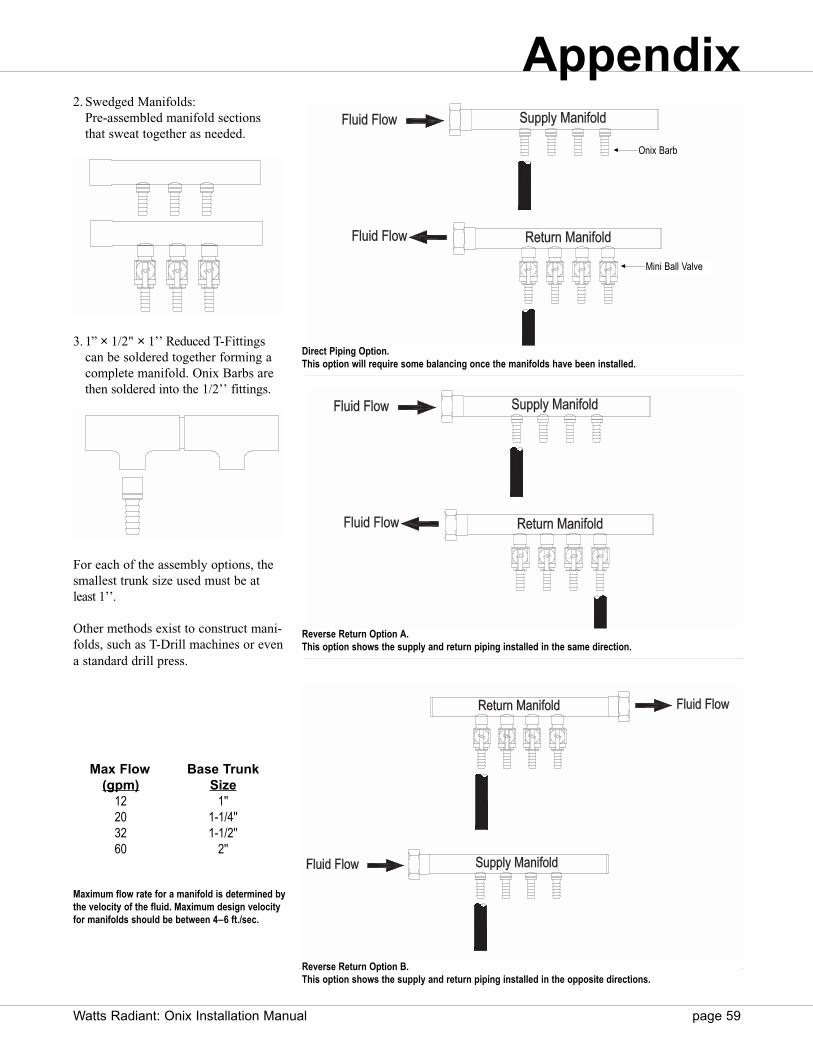
Watts Radiant: Onix Installation Manual page 59
2. Swedged Manifolds: Pre-assembled manifold sectionsthat sweat together as needed.
3. 1’’ × 1/2" × 1’’ Reduced T-Fittingscan be soldered together forming acomplete manifold. Onix Barbs arethen soldered into the 1/2’’ fittings.
For each of the assembly options, thesmallest trunk size used must be atleast 1’’.
Other methods exist to construct mani-folds, such as T-Drill machines or evena standard drill press.
Returnrn ManManifoldfold
Supppply ManManifoldfold
FlFluiuid Fd Flolow
FlFluiuid Fd Flolow
Supppply ManManifoldfoldFlFluiuid Fd Flolow
Returnrn ManManifoldfoldFlFluiuid Fd Flolow
Supppply ManManifofoldld
Returnrn ManManifofoldld
Fluid FloFluid Flow
Fluid FloFluid Flow
Direct Piping Option. This option will require some balancing once the manifolds have been installed.
Reverse Return Option A. This option shows the supply and return piping installed in the same direction.
Reverse Return Option B. This option shows the supply and return piping installed in the opposite directions.
Max Flow Base Trunk(gpm) Size
12 1''20 1-1/4''32 1-1/2''60 2''
Onix Barb
Mini Ball Valve
Maximum flow rate for a manifold is determined bythe velocity of the fluid. Maximum design velocityfor manifolds should be between 4–6 ft./sec.
Appendix
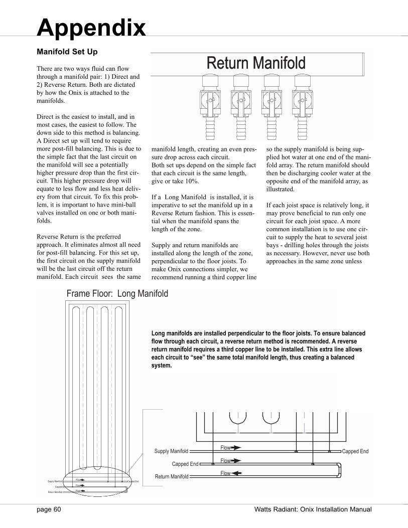
page 60 Watts Radiant: Onix Installation Manual
Manifold Set Up
There are two ways fluid can flowthrough a manifold pair: 1) Direct and2) Reverse Return. Both are dictatedby how the Onix is attached to themanifolds.
Direct is the easiest to install, and inmost cases, the easiest to follow. Thedown side to this method is balancing.A Direct set up will tend to requiremore post-fill balancing. This is due tothe simple fact that the last circuit onthe manifold will see a potentiallyhigher pressure drop than the first cir-cuit. This higher pressure drop willequate to less flow and less heat deliv-ery from that circuit. To fix this prob-lem, it is important to have mini-ballvalves installed on one or both mani-folds.
Reverse Return is the preferredapproach. It eliminates almost all needfor post-fill balancing. For this set up,the first circuit on the supply manifoldwill be the last circuit off the returnmanifold. Each circuit sees the same
manifold length, creating an even pres-sure drop across each circuit.Both set ups depend on the simple factthat each circuit is the same length,give or take 10%.
If a Long Manifold is installed, it isimperative to set the manifold up in aReverse Return fashion. This is essen-tial when the manifold spans thelength of the zone.
Supply and return manifolds areinstalled along the length of the zone,perpendicular to the floor joists. Tomake Onix connections simpler, werecommend running a third copper line
so the supply manifold is being sup-plied hot water at one end of the mani-fold array. The return manifold shouldthen be discharging cooler water at theopposite end of the manifold array, asillustrated.
If each joist space is relatively long, itmay prove beneficial to run only onecircuit for each joist space. A morecommon installation is to use one cir-cuit to supply the heat to several joistbays - drilling holes through the joistsas necessary. However, never use bothapproaches in the same zone unless
Returnrn ManManifoldfold
Supply Manifold
Fluid Flow
Fluid Flow
Frame Floor: Long Manifold
Flow
Flow
Flow
Capped End
Capped EndSupply Manifold
Return Manifold
Long manifolds are installed perpendicular to the floor joists. To ensure balancedflow through each circuit, a reverse return method is recommended. A reverse return manifold requires a third copper line to be installed. This extra line allowseach circuit to “see” the same total manifold length, thus creating a balanced system.
Flow
Flow
Flow
Capped End
Capped EndSupply Manifold
Return Manifold
Appendix
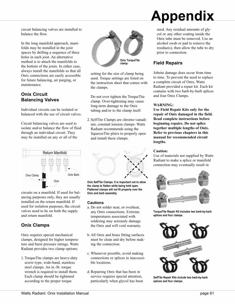
Watts Radiant: Onix Installation Manual page 61
circuit balancing valves are installed tobalance the flow.
In the long manifold approach, mani-folds may be installed in the joistspaces by drilling a sequence of threeholes in each joist. An alternativemethod is to attach the manifolds tothe bottom of the joists. In either case,always install the manifolds so that allOnix connections are easily accessiblefor future balancing, air purging, ormaintenance.
Onix Circuit Balancing Valves
Individual circuits can be isolated orbalanced with the use of circuit valves.
Circuit balancing valves are used toisolate and/or balance the flow of fluidthrough an individual circuit. Theymay be installed on any or all of the
circuits on a manifold. If used for bal-ancing purposes only, they are usuallyinstalled on the return manifold. Ifused for isolation purposes, the circuitvalves need to be on both the supplyand return manifold.
Onix Clamps
Onix requires special mechanicalclamps, designed for higher tempera-ture and burst pressure ratings. WattsRadiant provides two clamp options:
1. TorqueTite clamps are heavy-dutyscrew-type, wide-band, stainlesssteel clamps. An in.-lb. torquewrench is required to install them.Each clamp should be tightenedaccording to the proper torque
setting for the size of clamp beingused. Torque settings are listed onthe instruction sheet that comes withthe clamps.
Do not over tighten the TorqueTite clamp. Over-tightening may cause long-term damage to the Onix tubing and/or to the clamp itself.
2. SelfTite Clamps are chrome-vanadi-um, constant tension clamps. WattsRadiant recommends using theSqueezeTite pliers to properly openand install these clamps.
Cautionsa. Do not solder near, or overheat,
any Onix connections. Extreme temperatures associated with soldering may seriously damage the Onix and will void warranty.
b. All Onix and brass fitting surfacesmust be clean and dry before mak-ing the connection.
c. Whenever possible, avoid makingconnections or splices in inaccessi-ble locations.
d. Repairing Onix that has been inservice requires special attention,particularly when glycol has been
used. Any residual amounts of gly-col or any other coating inside theOnix tube must be removed. Use analcohol swab or pad to remove theresidue(s), then allow the tube to dryprior to connection.
Field Repairs
Jobsite damage does occur from timeto time. To prevent the need to replacea complete circuit of Onix, WattsRadiant provided a repair kit. Each kitcontains with two barb-by-barb splicesand four Onix Clamps.
WARNING:Use Field Repair Kits only for therepair of Onix damaged in the field.Read complete instructions beforebeginning repairs. Do not splicetogether multiple lengths of Onix.Refer to previous chapters in thismanual for recommended circuitlengths.
Caution:Use of materials not supplied by WattsRadiant to make a splice or manifoldconnection may eventually result in
SelfTite Repair Kits include two barb-by-barbsplices and four clamps.
Returnrn ManManifoldfold
Supply Manifold
Fluid Flow
Fluid Flow
Onix BarbOnix Clamp
Onix
Onix TorqueTiteclamp.
Onix SelfTite Clamps. It is important not to allowthe clamp to flatten while being held open.Flattened clamps will not fit properly over theOnix and barb assembly.
TorqueTite Repair Kit includes two barb-by-barbsplices and four clamps.
Appendix

page 62 Watts Radiant: Onix Installation Manual
leaks. Watts Radiant s Onix and fit-tings are engineered to work together.Watts Radiant extends no warranty expressed or implied to any failureor damage of any kind resulting fromuse of materials not supplied by WattsRadiant (see Onix warranty forspecifics).
1. Cut the Onix.Make a straight cut-off on bothpieces of Onix to be spliced together.
2. Select the Correct Brass Splice.Use only Watts Radiant brass splicesand clamps to repair Onix.
NOTE: Our research shows thatWatts Radiant brass fittings makethe best connections to Onix. Off-the-shelf brass fittings are made todifferent dimensions and tolerances.Do not use them.
3. Choose the Correct Clamp.Make sure to use the correctly-sizedstainless TorqueTite or SelfTiteclamp for making Onix connections.Identify the clamps by the sizemarkings on the clamps. Use:
TorqueTite Clamps17–19 mm for 3/8" Onix, 21–23 mm for 1/2" Onix, 25–27 mm for 5/8" Onix, 29–31 mm for 3/4" Onix, and 37–40 mm for 1" Onix.
SelfTite Clamps19 mm for 3/8" Onix,22 mm for 1/2" Onix,25 mm for 5/8" Onix, and 29 mm for 3/4" Onix,
Slide one clamp about three inches onto the length of the Onix.
4. Make the Connection.Slide both lengths of Onix onto thebrass splice. Slide the clamps backover the barbed area on both sides.The clamp should be applied to themiddle of the barbed area.
If using TorqueTite clamps, tightenthe clamp using only an in.-lb.
water, but not both) through side A.When filling with water, leave thedrain on side B open (side with thepressure gauge) until water comes out.Close the valve and fill until the zoneis pressurized to between 50 psi and100 psi. Do not test over 100 psi, asthis will ruin the gauge on the test kit.
If the temperature is below freezing,use air to pressure test. If a fluid mustbe used, use a 50-50 water/glycol solu-tion. Failure to use glycol may resultin frozen circuits.
The cool night air will usually causeless than a ten psi drop in pressure asthe water or air contracts from thecold. If there is more of a pressuredrop, or if there are other reasons tobelieve there is a leak, spray a soapysolution on all connections and inspectfor leaks. If there are still concernsabout leaks, increase the test pressureto 100 psi and inspect each of the cir-cuits. A leak should be visible.
NOTE: During pressure testing theends of each circuit where they con-nect to the manifolds may bubble forten or fifteen minutes each time thesystem is pressurized. This is due inpart to the pressure expanding theinner channel, driving small amountsof trapped air out of the braidingbetween the tube and cover. This isnormal and is not a concern, as long asthe system pressure does not drop.
Manifold
Pressure Test Kit
Pressure Gauge
Union
DrainSchraeder Valve
Appendixtorque wrench according to thetorque settings shown on the instruc-tion sheet that comes with theclamps.
Do not use a screw gun or wrenchto tighten TorqueTite clamps.Safety glasses must be worn ifusing SelfTite Clamps.
When making a buried slab repair,protect the final splice assembly with adouble wrap of PVC electrician s tapeor plastic shrink wrap.
Pressure Test
After the Onix and manifolds havebeen installed, it is time to pressuretest each zone. Individual test kits maybe field constructed or a factory sup-plied kit may be used. The followingdirections are specially directed to theuse of Watts Radiant test kits, althoughthe general principles remain the samefor field-built units.
Attach the pressure test kit to the man-ifolds. Watts Radiant manifolds andtest kits with optional unions, can easi-ly be hand tightened to hold up to 100psi. Make certain the rubber O-ring isproperly seated before threading theunions together.
One half of the Watts Radiant test kithas a Schraeder valve (air valve) onside A. The other half, side B, has apressure gauge. Fill the system (air or

Watts Radiant: Onix Installation Manual page 63
Typical Nomograph
Nomographs are generated byRadiantWorks as design aids for con-tractors and engineers for optimizingradiant floor heating designs. Eachnomograph is customized for a specif-ic room or zone within a project. Thefollowing is a brief explanation of howto interpret a nomograph.
Note: The accompanying slab nomo-graph is customized and should notbe generalized to frame floors, otherfloor coverings, other Onix sizes ordiffering indoor air temperatures.
On the upper left hand corner of thenomograph you will see the systemdesign parameters. In this case, thenomograph is for a slab with 1/4’’ tilewhere the desired indoor temperatureis 70¡F, the outdoor temperature is 0¡,
the project is at an altitude of 2000 ft.and 3/8’’ Onix is being installed.
The left vertical axis displays the radi-ant floor heat output intensity, asexpressed in BTU/h/sq.ft. of radiantfloor surface.
The right vertical axis displays theaverage floor surface temperature. Theactual floor surface temperature willvary –1¡F relative to the measurementlocation; that being taken over a cir-cuit or between two circuits. In generala system will need to be designed sothe average floor surface temperatureis 85¡F or below. Higher surface tem-peratures can be used if allowed byASHRAE guidelines and the floorcovering manufacturer.
The top axis on the nomographreflects the total heat loss through theedges and underneath the radiant floor.As the radiant floor heat loss increas-es, the mean water temperature in thefloor also increases. This heat loss isexpressed as BTU/h/sq.ft. of radiantfloor. It is calculated for each projectby RadiantWorks based upon the actu-al design parameters which includefloor insulation, floor covering andoverall system design.
The bottom horizontal axis shows theaverage, or mean, water temperatureflowing through the radiant circuits.This is not the entering water tempera-ture. For example, if the enteringwater temperature is 108¡F and theexiting temperature is 88¡F then themean temperature is 98¡F, the averageof the two.
Watts Heatway Nomograph © for Kitchen AreaSlab application with 3/8" Onix
Watts Radiant Nomograph © for Breakfast / Kitchen AreaSlab Application 3/8" Onix
Required Heat Load Line
Tube Spacing
Room’s Actual Conditions
Rad
iant
Flo
or H
eat O
utpu
t Int
ensi
ty [B
tu/h
sq.
ft.]
50
45
40
35
30
25
20
15
10
5
0
90
88
85
83
80
77
74
71
67
63
58
Effe
ctiv
e Fl
oor S
urfa
ce T
empe
ratu
re [°
F]
60 70 80 90 100 110 120 130 140 150 160 170 180 190 200 210 220 Mean Water Temperature [°F]98
6oc 9oc 12oc 15oc 18ocTotal Floor R-Value: 0.6Indoor Design Temp: 68[°F]Outdoor Design Temp: 0[°F]
Maximum Allowable Floor Surface Temperature
EXAMPLE ONLY
Appendix

page 64 Watts Radiant: Onix Installation Manual
The diagonal lines illustrate the designpossibilities if the spacing of the Onixtubing is adjusted.
Each diagonal line shows the heat out-put of a different Onix spacing, underthe same design parameters. Changesin the Onix size, supply water temper-ature or the R value of the floor cover-ing will make a difference in the heatoutput of the radiant slab.
This nomograph shows five possibleOnix spacings, ranging from 6" to 18"on center. Spacings greater than 12"are usually limited to certain commer-cial and industrial applications wherefloor temperature variations betweencircuits is not a design consideration.
Read the Nomograph from left toright. A possible solution exists wher-ever the horizontal line associated withthe heating intensity intersects thediagonal line associated with a particu-lar hose spacing, as long as therequired floor temperature is below themaximum floor temperature. If this isnot the case, and the required floortemperature is higher than the maxi-mum 85¡F floor surface temperature,auxiliary heat will be required.
Next, find the required mean watertemperature necessary to heat thegiven conditions. Mark the point onthe nomograph where the horizontalheat intensity line intercepts with ahose spacing. From that point, movedirectly down to the bottom axis. Thisis the required mean temperature.
For our example, the kitchen slabneeds to radiate 17 BTU/h/sq.ft. andwe choose an Onix spacing of 12’’ oncenter. The mean water temperaturewhere these two lines intersect isabout 92¡F, or 102¡F supply tempera-ture (based on a 20¡ temperaturedrop). If a 6’’ on center tube spacing isused, a mean water temperature of87¡F is required, or 97¡F supply tem-perature.
This tool should be used with care, as
the Onix spacing necessary to meet theload still may not satisfy the customer.For example, an 18’’ o.c. radiant circuitspacing in a home or office wouldlikely generate customer complaintsabout uneven floor surface tempera-tures. Also, care must also be takennot to exceed the warranty temperaturelimits of Watts Radiant products andthe installed flooring products.Generally speaking, mean water temperatures of 140¡F and belowshould be used for slab heating andmean water temperatures of 150¡F andbelow should be used for frame heating applications.
Pressure Drop Charts
Watts Radiant s pressure drop chartsare available for all sizes of Onix, forplain water, ethylene and propyleneglycol. Information regarding the heatrequired by the circuit (Qs), pressuredrop in the hose (ft.-hd./ft.), flow rate(gpm), and water velocity (ft./sec) canall be calculated from these charts.The charts are cataloged by averagewater temperatures required to heat aradiant zone, ranging from 100¡—180¡F. The following pressure dropcharts are for an average water tem-perature of 120¡F.
Example
The following example will demon-strate the use of these charts.
Assume the total heat required for aradiant zone is 16,000 BTU/h. Four,200’ circuits of 3/8’’ Onix are usedwith an average water temperature of120¡F.
The pressure drop for a circuit in thezone is calculated by following thesesteps.
1. Determine the heat required for eachcircuit in the zone.(16,000/4 = 4,000 BTU/h/circuit)
2. Find this number on the Qs axis (leftside of the chart).
3. Draw a horizontal line until it intersects the diagonal line for 3/8" Onix.
4. Drop a line vertically to read thepressure drop per foot of hose (0.03 ft.-hd/ft.)
5. Find the total length of the hose inthe circuit including the distance toand from the manifold. In this exam-ple the manifold is located in thezone (total length 200’)
6. Find the total pressure drop by multiplying the circuit length (in this case, 200’) by the pressure dropper foot of heat (in this case 0.03 ft.-hd./ft.)
Note: Follow steps 1—6 for other cir-cuits if the heat output and/or lengthsare different. The pump head is chosenaccording to the circuit having themaximum pressure drop. The pumpgpm is the summation of the gpm forall the circuits served by the pump.
There are many other uses for pressuredrop charts as well. Water velocity isshown on the chart by the short diago-nal lines that intersect the longer diag-onal lines for each specific energytransfer hose. If the flow rate or theheat required is known, the watervelocity can be found by tracing hori-zontally from either axis. In the aboveexample, the water velocity is approxi-mately 1.25 ft./sec. It is a good prac-tice to maintain water velocities above 1 ft./sec and below 5 ft./sec. Forinstance, 3/8’’ Onix in 200’ lengthsshould be designed to transfer at least3,000 BTU/h, and 5/8’’ Onix in 200’lengths should ordinarily be designedto transfer at least 9,000 BTU/h.
Flow rate per circuit at 20¡F ∆T can be found by continuing horizontallyfrom the heat required (Qs) per circuit(on the left side of the chart) and
Appendix
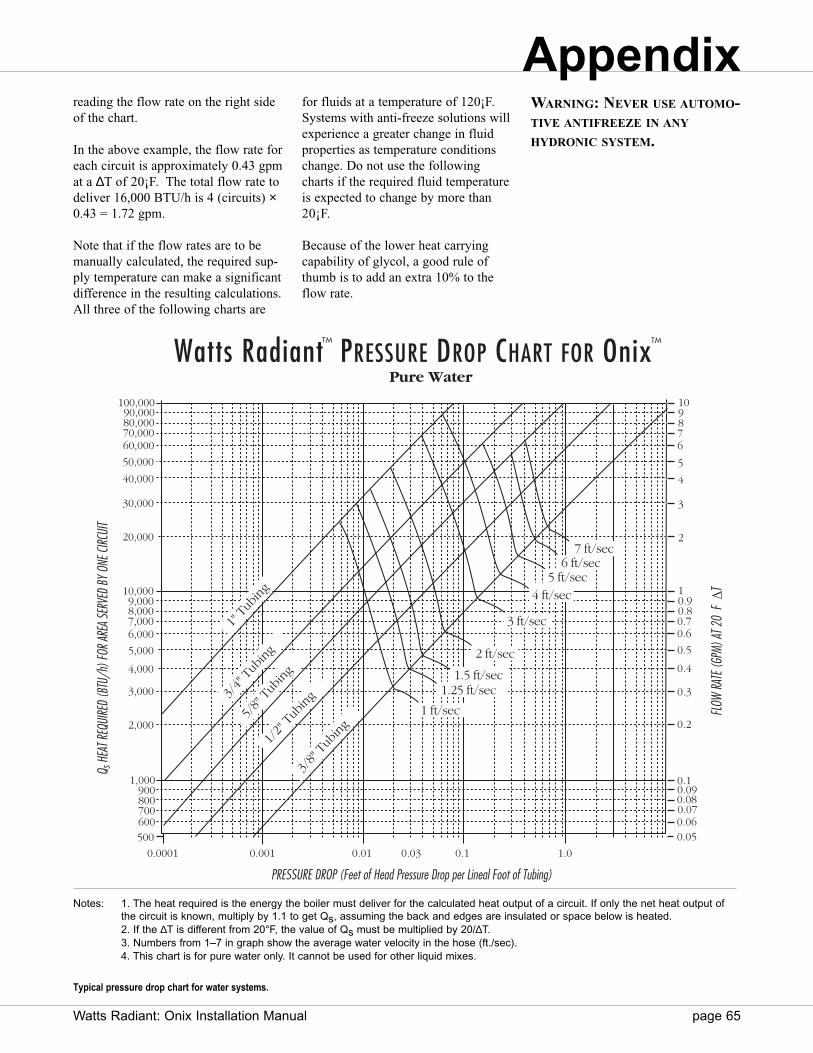
Watts Radiant: Onix Installation Manual page 65
reading the flow rate on the right sideof the chart.
In the above example, the flow rate foreach circuit is approximately 0.43 gpmat a ∆T of 20¡F. The total flow rate todeliver 16,000 BTU/h is 4 (circuits) ×0.43 = 1.72 gpm.
Note that if the flow rates are to bemanually calculated, the required sup-ply temperature can make a significantdifference in the resulting calculations.All three of the following charts are
for fluids at a temperature of 120¡F.Systems with anti-freeze solutions willexperience a greater change in fluidproperties as temperature conditionschange. Do not use the followingcharts if the required fluid temperatureis expected to change by more than20¡F.
Because of the lower heat carryingcapability of glycol, a good rule ofthumb is to add an extra 10% to theflow rate.
WARNING: NEVER USE AUTOMO-TIVE ANTIFREEZE IN ANY
HYDRONIC SYSTEM.
0.0001 0.001 0.01 0.10.03 1.0
3/8"
Tub
ing
1/2"
Tub
ing
5/8"
Tub
ing
3/4"
Tub
ing
40,000
30,000
20,000
10,0009,0008,0007,0006,000
5,000
4,000
3,000
2,000
1,000900800700600500
5
4
3
2
10.90.80.70.6
0.5
0.4
0.3
0.2
0.10.090.080.070.060.05
PRESSURE DROP (Feet of Head Pressure Drop per Lineal Foot of Tubing)
1 ft/sec
2 ft/sec
3 ft/sec
7 ft/sec
1.5 ft/sec
5 ft/sec
Watts Radiant PRESSURE DROP CHART FOR Onix Pure Water
TMTM
1.25 ft/sec
4 ft/sec
6 ft/sec
FLOW
RATE
(GPM
) AT 2
0 F
T
Q s H
EAT R
EQUI
RED
(BTU
/h) F
OR AR
EA S
ERVE
D BY
ONE
CIRC
UIT
10 9876
50,000
60,00070,00080,00090,000
100,000
1" T
ubin
g
Notes: 1. The heat required is the energy the boiler must deliver for the calculated heat output of a circuit. If only the net heat output of the circuit is known, multiply by 1.1 to get Qs, assuming the back and edges are insulated or space below is heated.2. If the ∆T is different from 20°F, the value of Qs must be multiplied by 20/∆T.3. Numbers from 1–7 in graph show the average water velocity in the hose (ft./sec).4. This chart is for pure water only. It cannot be used for other liquid mixes.
Typical pressure drop chart for water systems.
Appendix
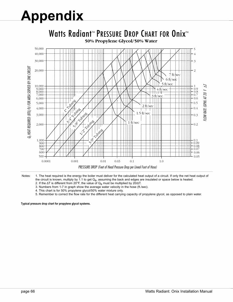
PRESSURE DROP (Feet of Head Pressure Drop per Lineal Foot of Hose)
Watts Radiant PRESSURE DROP CHART FOR Onix50% Propylene Glycol/50% Water
TMTM
FLOW
RATE
(GPM
) AT 2
0 F
T
Q s H
EAT R
EQUI
RED
(BTU
/h) F
OR AR
EA SE
RVED
BY
ONE C
IRCUI
T
0.0001 0.001 0.01 0.10.03 1.0
3/8"
Tub
ing
1/2"
Tub
ing
5/8"
Tub
ing
3/4"
Tub
ing
40,000
30,000
20,000
10,0009,0008,0007,0006,000
5,000
4,000
3,000
2,000
1,000900800700600500
1 ft/sec
2 ft/sec
3 ft/sec
7 ft/sec
1.5 ft/sec
5 ft/sec
4 ft/sec
6 ft/sec
5
4
3
2
10.90.80.70.6
0.5
0.4
0.3
0.2
0.10.090.080.070.06
1" T
ubin
g
0.05
50,000
Notes: 1. The heat required is the energy the boiler must deliver for the calculated heat output of a circuit. If only the net heat output of the circuit is known, multiply by 1.1 to get Qs, assuming the back and edges are insulated or space below is heated.2. If the ∆T is different from 20°F, the value of Qs must be multiplied by 20/∆T.3. Numbers from 1-7 in graph show the average water velocity in the hose (ft./sec).4. This chart is for 50% propylene glycol/50% water mixture only.5. Remember to correct the flow rate for the different heat carrying capacity of propylene glycol, as opposed to plain water.
page 66 Watts Radiant: Onix Installation Manual
Typical pressure drop chart for propylene glycol systems.
Appendix

Watts Radiant: Onix Installation Manual page 67
PRESSURE DROP (Feet of Head Pressure Drop per Lineal Foot of Tubing)
Q s H
EAT R
EQUI
RED
(BTU
/h) F
OR AR
EA SE
RVED
BY
ONE C
IRCUI
TWatts Radiant PRESSURE DROP CHART FOR Onix
50% Ethylene Glycol/50% Water
TMTM
FLOW
RATE
(GPM
) AT 2
0 F
T
0.0001 0.001 0.01 0.10.03 1.0
3/8"
Tub
ing
1/2"
Tub
ing
5/8"
Tub
ing
3/4"
Tub
ing
40,000
30,000
20,000
10,0009,0008,0007,0006,000
5,000
4,000
3,000
2,000
1,000900800700600
500
5
4
3
2
10.90.80.70.6
0.5
0.4
0.3
0.2
0.10.090.080.070.06
1 ft/sec
2 ft/sec
3 ft/sec
7 ft/sec
1.5 ft/sec
5 ft/sec
4 ft/sec
6 ft/sec
0.05
50,000
1" T
ubin
g
Notes: 1. The heat required is the energy the boiler must deliver for the calculated heat output of a circuit. If only the net heat output of the circuit is known, multiply by 1.1 to get Qs, assuming the back and edges are insulated or space below is heated.2. If the ∆T is different from 20°F, the value of Qs must be multiplied by 20/∆T.3. Numbers from 1-7 in graph show the average water velocity in the hose (ft./sec).4. This chart is for 50% ethylene glycol/50% water mixture only.5. Remember to correct the flow rate for the different heat carrying capacity of ethylene glycol, as opposed to plain water.
Typical pressure drop chart for ethylene glycol systems.
Appendix
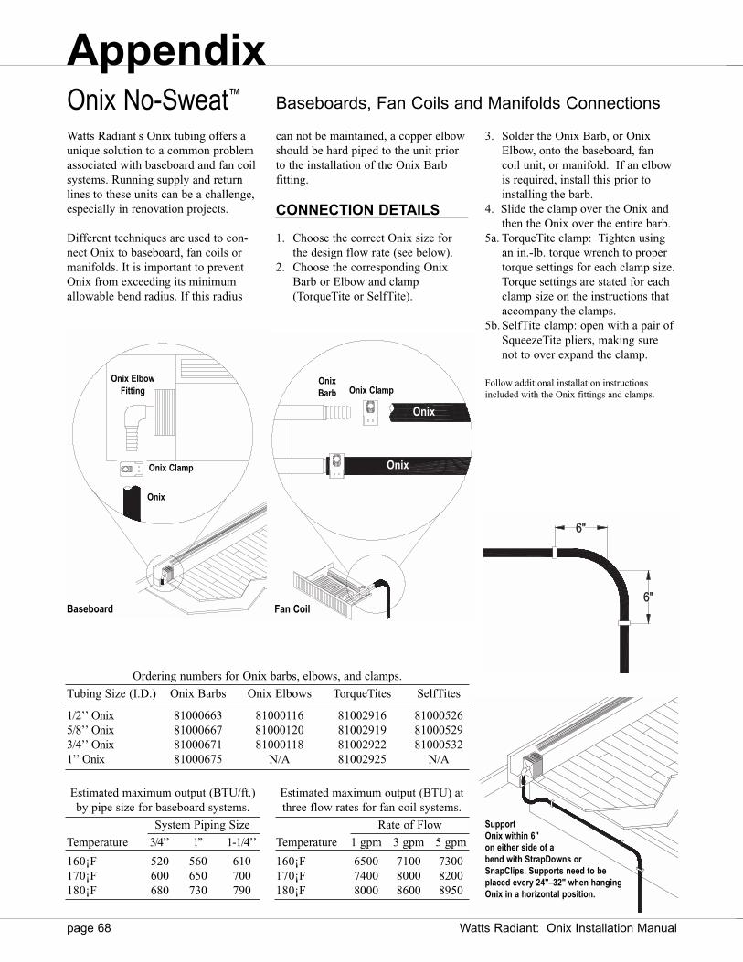
SupportOnix within 6"on either side of abend with StrapDowns orSnapClips. Supports need to beplaced every 24"–32" when hangingOnix in a horizontal position.
page 68 Watts Radiant: Onix Installation Manual
Fan CoilBaseboard
Baseboards, Fan Coils and Manifolds ConnectionsOnix No-Sweat™
Watts Radiant s Onix tubing offers aunique solution to a common problemassociated with baseboard and fan coilsystems. Running supply and returnlines to these units can be a challenge,especially in renovation projects.
Different techniques are used to con-nect Onix to baseboard, fan coils ormanifolds. It is important to preventOnix from exceeding its minimumallowable bend radius. If this radius
can not be maintained, a copper elbowshould be hard piped to the unit priorto the installation of the Onix Barb fitting.
CONNECTION DETAILS
1. Choose the correct Onix size for the design flow rate (see below).
2. Choose the corresponding Onix Barb or Elbow and clamp (TorqueTite or SelfTite).
3. Solder the Onix Barb, or Onix Elbow, onto the baseboard, fan coil unit, or manifold. If an elbow is required, install this prior to installing the barb.
4. Slide the clamp over the Onix and then the Onix over the entire barb.
5a. TorqueTite clamp: Tighten using an in.-lb. torque wrench to proper torque settings for each clamp size.Torque settings are stated for eachclamp size on the instructions that accompany the clamps.
5b. SelfTite clamp: open with a pair of SqueezeTite pliers, making sure not to over expand the clamp.
Follow additional installation instructionsincluded with the Onix fittings and clamps.
OnixBarb Onix Clamp
Onix
Onix
Onix ElbowFitting
Onix Clamp
Onix
Ordering numbers for Onix barbs, elbows, and clamps.
Tubing Size (I.D.) Onix Barbs Onix Elbows TorqueTites SelfTites
1/2’’ Onix 81000663 81000116 81002916 810005265/8’’ Onix 81000667 81000120 81002919 810005293/4’’ Onix 81000671 81000118 81002922 810005321’’ Onix 81000675 N/A 81002925 N/A
Estimated maximum output (BTU/ft.)by pipe size for baseboard systems.
System Piping Size
Temperature 3/4’’ 1’’ 1-1/4’’
160¡F 520 560 610170¡F 600 650 700180¡F 680 730 790
Estimated maximum output (BTU) atthree flow rates for fan coil systems.
Rate of Flow
Temperature 1 gpm 3 gpm 5 gpm
160¡F 6500 7100 7300170¡F 7400 8000 8200180¡F 8000 8600 8950
6"
6"
Appendix
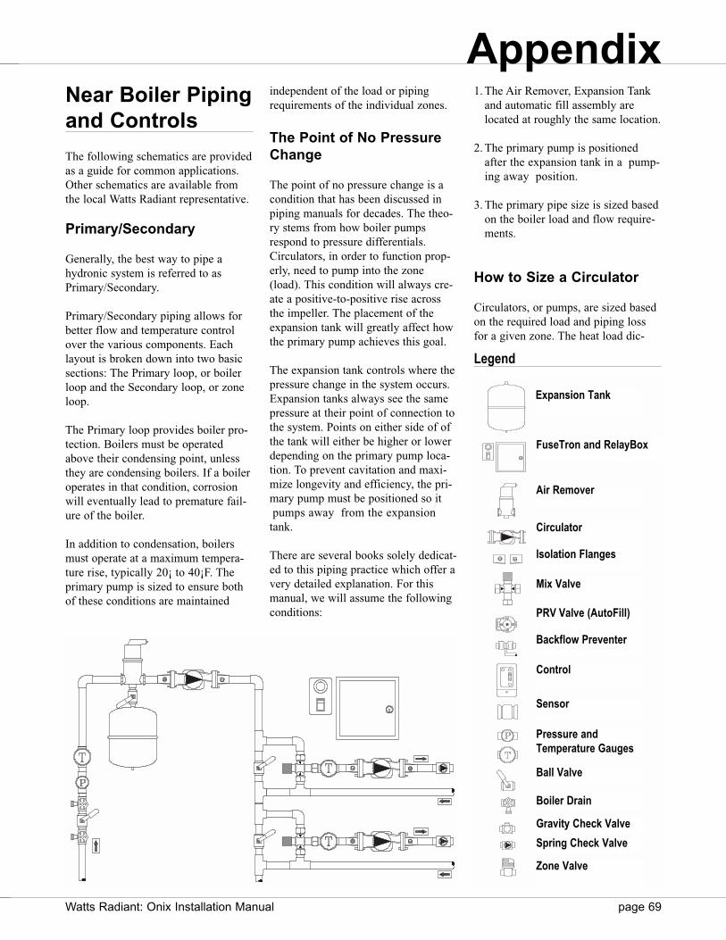
Near Boiler Pipingand Controls
The following schematics are providedas a guide for common applications.Other schematics are available fromthe local Watts Radiant representative.
Primary/Secondary
Generally, the best way to pipe ahydronic system is referred to asPrimary/Secondary.
Primary/Secondary piping allows forbetter flow and temperature controlover the various components. Eachlayout is broken down into two basicsections: The Primary loop, or boilerloop and the Secondary loop, or zoneloop.
The Primary loop provides boiler pro-tection. Boilers must be operatedabove their condensing point, unlessthey are condensing boilers. If a boileroperates in that condition, corrosionwill eventually lead to premature fail-ure of the boiler.
In addition to condensation, boilersmust operate at a maximum tempera-ture rise, typically 20¡ to 40¡F. Theprimary pump is sized to ensure bothof these conditions are maintained
independent of the load or pipingrequirements of the individual zones.
The Point of No PressureChange
The point of no pressure change is acondition that has been discussed inpiping manuals for decades. The theo-ry stems from how boiler pumpsrespond to pressure differentials.Circulators, in order to function prop-erly, need to pump into the zone(load). This condition will always cre-ate a positive-to-positive rise acrossthe impeller. The placement of theexpansion tank will greatly affect howthe primary pump achieves this goal.
The expansion tank controls where thepressure change in the system occurs.Expansion tanks always see the samepressure at their point of connection tothe system. Points on either side of ofthe tank will either be higher or lowerdepending on the primary pump loca-tion. To prevent cavitation and maxi-mize longevity and efficiency, the pri-mary pump must be positioned so itpumps away from the expansion
tank.
There are several books solely dedicat-ed to this piping practice which offer avery detailed explanation. For thismanual, we will assume the followingconditions:
1. The Air Remover, Expansion Tankand automatic fill assembly arelocated at roughly the same location.
2. The primary pump is positionedafter the expansion tank in a pump-ing away position.
3. The primary pipe size is sized basedon the boiler load and flow require-ments.
How to Size a Circulator
Circulators, or pumps, are sized basedon the required load and piping lossfor a given zone. The heat load dic-
Expansion Tank
FuseTron and RelayBox
Air Remover
Circulator
Isolation Flanges
Mix Valve
PRV Valve (AutoFill)
Backflow Preventer
Control
Sensor
Pressure and Temperature Gauges
Ball Valve
Boiler Drain
Gravity Check Valve
Spring Check Valve
Zone Valve
Legend
Appendix
Watts Radiant: Onix Installation Manual page 69

page 70 Watts Radiant: Onix Installation Manual
tates the required flow rate (gpm) forthe zone. This can be calculated byusing the following equation:
Pure Water:BTU = gpm × 500 × ∆T
50% Glycol-50% Water:BTU = gpm × 455 × ∆T
For most heating systems using a 20¡Ftemperature drop it can be assumed
1 gpm = 10,000 BTU/h
So, a system requiring 100,000 BTU/hwill need 10 gpm of flow.
The other performance factor in sizinga circulator is the head pressure. HeadPressure is the friction loss associatedwith the water moving against theinside surface of the tubing or pipe.The circulator should be sized to over-come this loss, while moving therequired volume of system fluid.
The zone head pressure is the pressuredrop seen through the Onix circuits ina given zone. It is calculated using thepressure drop charts and is added tothe pressure drop associated with thesupply and return piping.
Because the Onix circuits are alwaysplumbed in parallel, the pressure dropfor an individual circuit is the same asthe zone pressure drop.
Example:
Zone A calls for 20,000 BTU/h tobe delivered to a zone with 5’—200’ circuits of 3/8" Onix. The manifold islocated 20’ from the mechanical room.
Step 1: Determine the zone flow rate.
The flow rate for the zone is 20,000/10,000 = 2 gpm.
Step 2:Determine the circuit flow rate.
The flow rate through each circuit is 2 gpm/5 circuits = 0.40 gpm/circuit
Step 3:Determine the zone pressuredrop
Using the pressure drop chart forwater, the pressure drop per foot oftubing is 0.031 ft.-hd./ft. tubing. Thisgives a zone pressure drop of 0.031 × 200 = 6.20 ft.-hd.
Step 4:Determine the pressure drop ofthe supply/return lines.
Assuming 3/4" supply lines areinstalled, with a flow rate of 2 gpm.0.02 × 40’ (supply and return dis-tance) = 0.80 ft.-hd.
Step 5:Determine complete pump spec.
The required pump load is 2 gpm at(6.20 + 0.80) or 7.0 ft.-hd.
The actual pump required for this zoneis selected using the given manufactur-er s guidelines. This is usually donewith the use of a pump curve chart.The chart is set up showing the pumpscapacity at various pressure drops.Choose the pump that best reflects theneeds of the system.
For this example, pump 2 is the bestchoice.
This information is readily availableon a pump sizing chart. These chartsare created by the pump manufacturerfor each pump model and should beconsulted before selection of a pumpcan be made.
Expansion Tank Sizing
Water will expand as its temperatureincreases. Since a hydronic heatingsystem with an expansion tank is aclosed system, the internal fluid vol-ume is fixed. A simple ratio of how thevolume, pressure and temperature ofthe system interact can be modeled byusing a simplified version of the idealgas law.
1
2
3
2
4
6
8
2 4 6 8 10
10
Flow Rate (GPM)
Hea
d Pr
essu
re (f
t-hd)
Typical pump sizing chart. Make sure zone circulators are sized to include supply and returnpiping in addition to the zone piping requirements.
Appendix

PV = T(Pressure x Volume = Temperature)
With a fixed system volume, if the ini-tial water temperature is 50¡ and it israised to 180¡, the internal pressurewill increase, since the volume can notchange. By quadrupling the internaltemperature, the internal pressure willalso quadruple, changing it from aninitial 15 to 60 psi. This can damagesystem components and/or cause reliefvalves to discharge.
In order to keep the internal pressureroughly the same, the system volumehas to change. The question is by howmuch? What tank size would berequired if the temperature changedfrom 50¡ to 180¡ and the fluid volumewas 20 gallons (approximately 2400’of radiant tubing). Since we are deal-ing with an incompressible fluid, ele-vation will factor into the total expan-sion rate of the system. A step-by-stepform can be found in this section,along with other useful charts fordetermining component volumes.
Step 1:Determine the initial volume of thesystem. To do this, calculate the vol-ume of fluid in the tubing, supply-return piping, and all other mechanicalcomponents.
Step 2:Determine the static pressure of thesystem. The static pressure is the forceexerted on the system from the weightof the water above the mechanicalroom. The relative elevation change ofthe system will dictate how much stat-ic pressure is in the system.
Step 3:Determine the fill pressure of the sys-tem. This is the static pressure plus afactor of safety. In our case, 3 psi ismore than enough to account forminor piping variations within a floor.
Step 4:Find the allowable volume increase,which is a percentage, in the system.This percentage will be determined bymaximum pressure rating for the sys-tem, which is usually dictated by thepressure relief valve.
Step 5:Find what the actual volume increasewill be for the fluid. This is done bymultiplying the initial volume by thecorresponding temperature factor. Thehigher the temperature, the moreexpansion the fluid will undergo.
Step 6:Find the expansion tank volume bydividing the actual volume increase bythe percentage.
There are several educational books onthe market that describe primary/sec-ondary piping arrangements.
Expansion Tank Sizing form
Step 1: System Volume
Determine the amount of fluid in the radiant tubing, supply and return lines and near boiler piping (include boiler and other accessories).
Pipe Length × Volume/Foot* = Fluid Volume
Radiant PipingSupply/Return Piping
Boiler Volume(see boiler manual)
Total Volume (TV):
Total System Volume Includes:Boiler (see manufacturer s specifications) Optional Buffer TankFancoils RadiatorsRadiant Supply/Return Lines Additional Hydronic Components
Tank Size =
Fill Pressure = (No. of floors × 3.87 + 7 psi) + 14.7 =
Expansion Volume (EV) = Total Volume (TV) × Expansion Factor
EV =
AF = =
Tank Size = =
* See system volume table on the following page.See table of expansion factors on the following page.
Expansion Volume (EV)Acceptance Factor (AF)
(Relief Pressure + 14.7) — Fill Pressure(Relief Pressure + 14.7)
(EV)(AF)
Appendix
Watts Radiant: Onix Installation Manual page 71

page 72 Watts Radiant: Onix Installation Manual
For more detailed information, pleaseread these other publications. Thismanual is designed to give a basicunderstanding of primary/secondarypiping and to offer several pipingschematics as well as some correspon-ding electrical diagrams. WattsRadiant is not responsible for the per-formance or functionality of theseillustrative diagrams to any particularproject. Please consult a professionalmechanical contractor or a WattsRadiant representative for detailedadvice.
Mixing Options
Controlling the supply fluid tempera-ture to the zones is one of the morecritical features of the mechanical sys-tem design. There are several ways to
achieve this goal, including 3-way mixvalves, 4-way mix valves, injectionpumps, and even standard ball valves.The most common means is to useeither a three way mix valve or aninjection pump.
Mix Valves
Non-electrical mix valves are designedto provided a fixed supply temperaturewhenever there is a call for heat.
This reduced temperature is achievedby allowing a controlled amount ofhigh temperature boiler water to mixwith the cooler return water from thezone. It is important to choose a mixvalve that has enough flow volume forthe zone design.
Mix valves are sized based on a Cvvalue. This value corresponds to thepressure drop generated by a certainamount of flow. If a valve is rated witha Cv of 5, then the valve can move 5gpm of fluid at 1 psi drop (2.31 ft.-hd.)through the valve.
If only one zone is being pumpedthrough a mix valve, make sure thezone flow requirement is below the Cvvalue of the pump. If multiple zones(pumps) are to be supplied by onevalve, then make sure the combinedflow of the zones does not exceed theCv value of the valve. See followingpages for sample piping schematics.
To determine the pressure dropthrough the mix valve at a given flowrate, use the following equation:
where SG is the specific gravity of thefluid (for water this is 1, for glycol thisis 1.15), and P is the pressure dropthrough the valve.
The total pressure drop for the zone isthe combination of the pressure dropfound through the zone, supply/returnpiping and the mix valve.
Most manufacturers will provide thisinformation in a graph similar to whatis seen for pump sizing. Consult thecorresponding mix valve manufacturerfor more sizing information.
Water
System ExpansionTemperature (¡F) Factor
105 0.004110 0.005115 0.007120 0.008125 0.010130 0.012135 0.013140 0.015145 0.017150 0.018155 0.020160 0.022165 0.023170 0.025175 0.026180 0.028185 0.030190 0.032195 0.033200 0.035205 0.037210 0.039
Expansion Factors.
Glycol
System ExpansionTemperature (¡F) Factor
105 0.0048110 0.006115 0.0084120 0.0096125 0.012130 0.0144135 0.0156140 0.018145 0.0204150 0.0216155 0.024160 0.0264165 0.0276170 0.030175 0.0312180 0.0336185 0.036190 0.0384195 0.0396200 0.042205 0.0444210 0.0468
System volume chart.
Tubing I.D. Onix-PEX Fluid Capacity Type M Copper Fluid Capacity
3/8" 6.25 gal./1000 ft. 8.31 gal./1000 ft.1/2" 10.25 gal./1000 ft. 13.2 gal./1000 ft.5/8" 16.0 gal./1000 ft. 18.1 gal./1000 ft.3/4" 25.0 gal./1000 ft. 27.0 gal./1000 ft.1" N/A 45.5 gal./1000 ft.
1-1/4" N/A 68.2 gal./1000 ft.1-1/2" N/A 95.4 gal./1000 ft.
Mix Valve
Temperature Gauge
Appendix
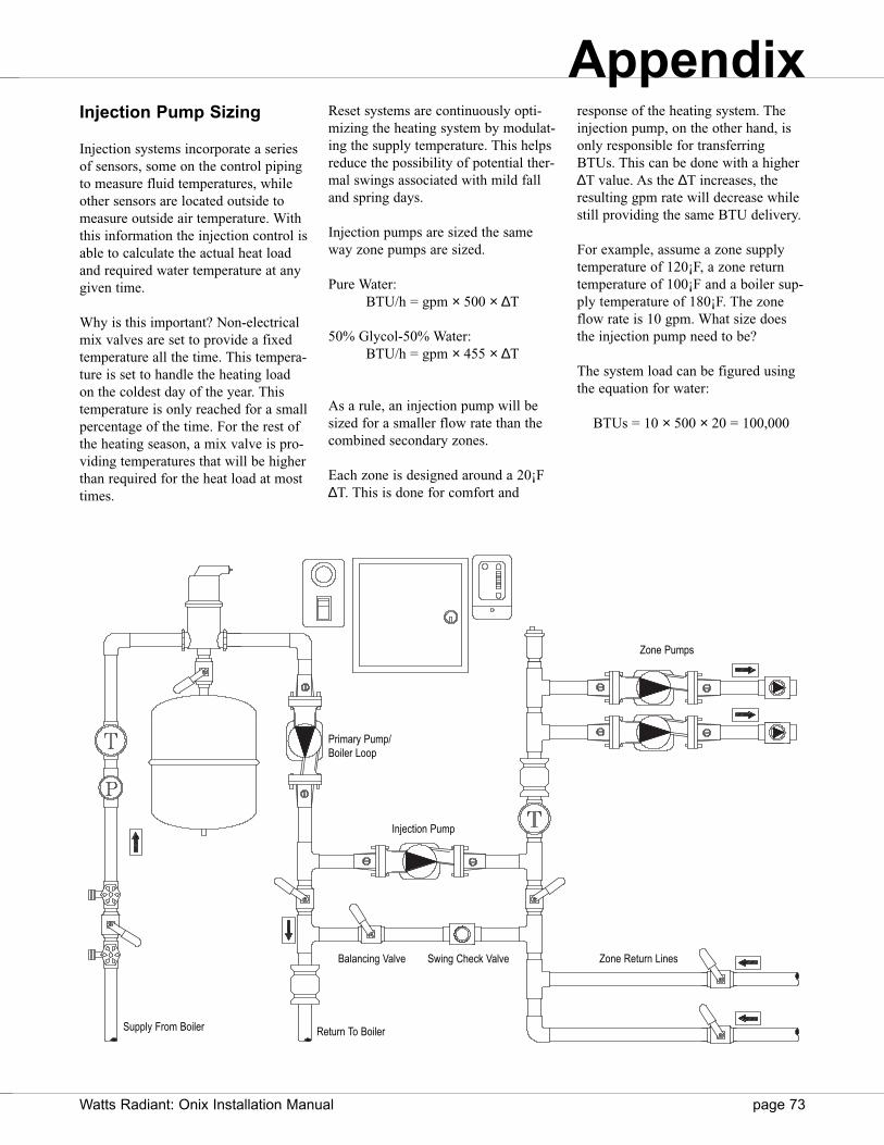
Injection Pump Sizing
Injection systems incorporate a seriesof sensors, some on the control pipingto measure fluid temperatures, whileother sensors are located outside tomeasure outside air temperature. Withthis information the injection control isable to calculate the actual heat loadand required water temperature at anygiven time.
Why is this important? Non-electricalmix valves are set to provide a fixedtemperature all the time. This tempera-ture is set to handle the heating loadon the coldest day of the year. Thistemperature is only reached for a smallpercentage of the time. For the rest ofthe heating season, a mix valve is pro-viding temperatures that will be higherthan required for the heat load at mosttimes.
Reset systems are continuously opti-mizing the heating system by modulat-ing the supply temperature. This helpsreduce the possibility of potential ther-mal swings associated with mild falland spring days.
Injection pumps are sized the sameway zone pumps are sized.
Pure Water:BTU/h = gpm × 500 × ∆T
50% Glycol-50% Water:BTU/h = gpm × 455 × ∆T
As a rule, an injection pump will besized for a smaller flow rate than thecombined secondary zones.
Each zone is designed around a 20¡F∆T. This is done for comfort and
response of the heating system. Theinjection pump, on the other hand, isonly responsible for transferringBTUs. This can be done with a higher∆T value. As the ∆T increases, theresulting gpm rate will decrease whilestill providing the same BTU delivery.
For example, assume a zone supplytemperature of 120¡F, a zone returntemperature of 100¡F and a boiler sup-ply temperature of 180¡F. The zoneflow rate is 10 gpm. What size doesthe injection pump need to be?
The system load can be figured usingthe equation for water:
BTUs = 10 × 500 × 20 = 100,000
Zone Pumps
Injection Pump
Primary Pump/Boiler Loop
Zone Return LinesSwing Check ValveBalancing Valve
Supply From Boiler Return To Boiler
Appendix
Watts Radiant: Onix Installation Manual page 73

page 74 Watts Radiant: Onix Installation Manual
The required flow rate for the injectionpump can now be determined.
100,000 = gpm × 500 × (180 — 100)
gpm = 2.5
The ∆T is figured using the supplytemperature and return temperatureacross the injection loop. This is theboiler supply temperature minus thezone return temperature.
Note: In most cases the pressure drop across the injection loop will beminimal.
Appendix

Piping and Electrical Diagrams
W1 R
Blue
Yellow
White
Green
Black
White
Green
Black
BIM L N G
Blue
White
White
Green
Blu
e
Blu
e
Black
Bla
ck
Bla
ck
Blu
e
Yel
low
PP P1
Fusetron
Transformer
Blu
e
One zone off boiler
The schematic shown illustrates a single-zone system, where a non-electric mixing valve is being used. Piping Schematic
Electrical Diagram
Appendix
Watts Radiant: Onix Installation Manual page 75

page 76 Watts Radiant: Onix Installation Manual
W1 W2 W3 R R R
Blue
Yellow
White
Green
Black
White
Green
Black
BIM L N G
Blue
White
White
Green
Blu
e
Blu
eBlack
Bla
ck
Bla
ck
Blu
e
Blu
e
Yel
low
Yellow
Blu
e
Yel
low
Bla
ck
Bla
ck
Blu
e
Bla
ck
Bla
ck
Blu
e
PP P1 P2 P3
Fusetron
Transformer
Blu
eB
lue
Blu
e
Multiple zones off boiler
The schematic shown illustrates amulti-zone system, where twonon-electric mixing valves arebeing used.
Piping Schematic
Electrical Diagram
Appendix

Blu
e
Yel
low
/Gre
en
White
Green
Black
White
Green
Black
L N G
PP
Fusetron
Transformer
R W W W
Black
White
Black
ThermostatHook-ups
Supp
ly/R
etur
n
21 53 4 86 7 9
P1 INJ
Bla
ck
Green
White
P2 P3
Bla
ck
Bla
ck
WhiteWhite
Black
Red
Black
Multiple zones off boiler with injection pump mixing
The schematic shown illustrates a multi-zone sys-tem, where two zoned circulators are being sup-plied by an injection pump.
Tekmar 353 Injection Control
Piping Schematic
Electrical Diagram
Appendix
Watts Radiant: Onix Installation Manual page 77

page 78 Watts Radiant: Onix Installation Manual
Notes

Watts Radiant: Onix Installation Manual page 79
PowerupwithRadiantWorks
• Reworked load calculations to correspond with 2004 ASHRAE Manuals
• Redesigned graphical user interface• Real time load and fluid temperature
calculations• Redesigned reports
• Tubing Layout Utility: Automatically calculates and lays out the tubing; import/export DXF drawings
• Integrated Watts Radiant catalog• Many new templates and defaults to speed up
the design process
®
The Premier Radiant Heating Design PackageTurbocharged for 2005!
Totally New or Enhanced Capabilities for ’05
ComingSumm
er2005
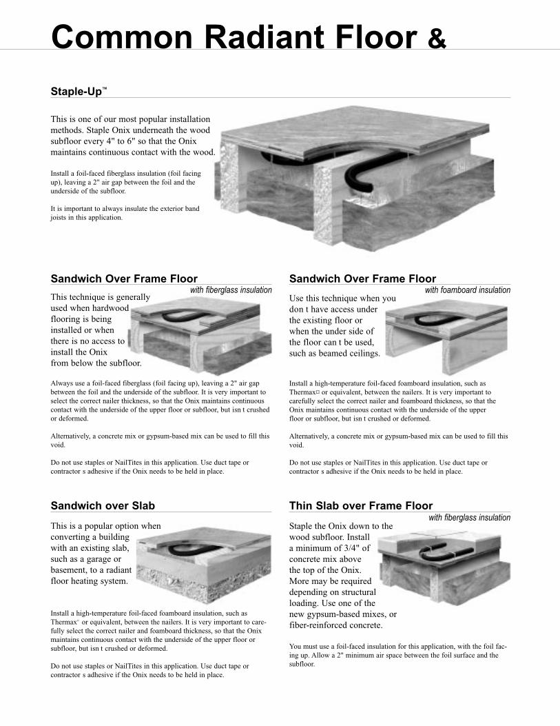
Common Radiant Floor &
This is one of our most popular installation methods. Staple Onix underneath the wood subfloor every 4" to 6" so that the Onix maintains continuous contact with the wood.
Install a foil-faced fiberglass insulation (foil facing up), leaving a 2" air gap between the foil and the underside of the subfloor.
It is important to always insulate the exterior band joists in this application.
Staple-Up™
This technique is generally used when hardwood flooring is being installed or when there is no access to install the Onix from below the subfloor.
Always use a foil-faced fiberglass (foil facing up), leaving a 2" air gapbetween the foil and the underside of the subfloor. It is very important toselect the correct nailer thickness, so that the Onix maintains continuouscontact with the underside of the upper floor or subfloor, but isn t crushedor deformed.
Alternatively, a concrete mix or gypsum-based mix can be used to fill thisvoid.
Do not use staples or NailTites in this application. Use duct tape or contractor s adhesive if the Onix needs to be held in place.
Sandwich Over Frame Floor
Use this technique when you don t have access under the existing floor or when the under side of the floor can t be used, such as beamed ceilings.
Install a high-temperature foil-faced foamboard insulation, such asThermax¤ or equivalent, between the nailers. It is very important to carefully select the correct nailer and foamboard thickness, so that theOnix maintains continuous contact with the underside of the upper floor or subfloor, but isn t crushed or deformed.
Alternatively, a concrete mix or gypsum-based mix can be used to fill thisvoid.
Do not use staples or NailTites in this application. Use duct tape or contractor s adhesive if the Onix needs to be held in place.
Sandwich Over Frame Floor
This is a popular option when converting a building with an existing slab, such as a garage or basement, to a radiant floor heating system.
Install a high-temperature foil-faced foamboard insulation, such asThermax¤ or equivalent, between the nailers. It is very important to care-fully select the correct nailer and foamboard thickness, so that the Onixmaintains continuous contact with the underside of the upper floor or subfloor, but isn t crushed or deformed.
Do not use staples or NailTites in this application. Use duct tape or contractor s adhesive if the Onix needs to be held in place.
Sandwich over Slab
Staple the Onix down to the wood subfloor. Install a minimum of 3/4" of concrete mix above the top of the Onix. More may be required depending on structural loading. Use one of the new gypsum-based mixes, or fiber-reinforced concrete.
You must use a foil-faced insulation for this application, with the foil fac-ing up. Allow a 2" minimum air space between the foil surface and thesubfloor.
Thin Slab over Frame Floor
with fiberglass insulation with foamboard insulation
with fiberglass insulation
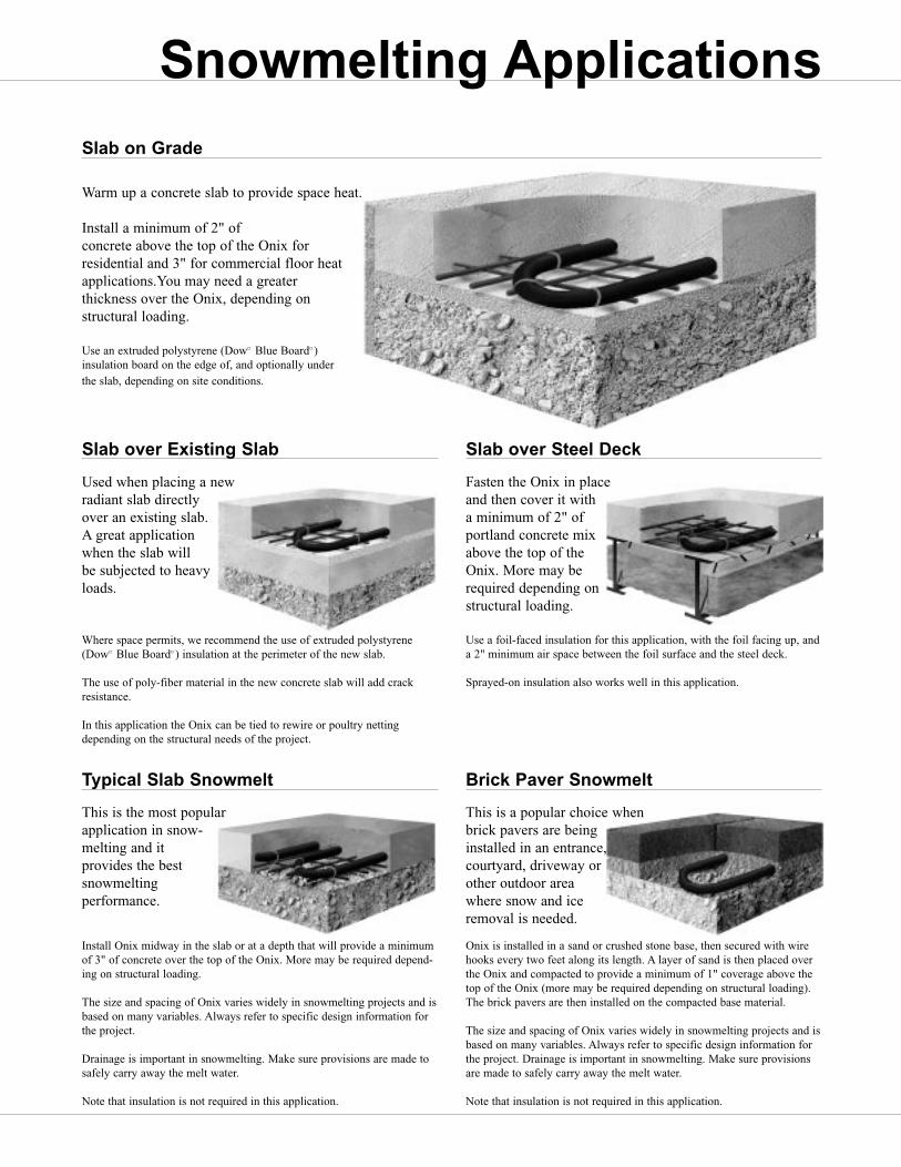
This Onix Installation Manual represents the
collective knowledge of thousands of our cus-
tomers who have been kind enough to furnish us
with ideas and techniques that have worked for
them. We have selected the best of these ideas
and rigorously refined them.
This refining process is based on the collective
wisdom that comes from having an engineering
and technical staff with over 200 years of
combined experience with modern floor heating
and snowmelting. Please take the time to
carefully read this manual before installing your
floor heating or snowmelting system.
PLEASE NOTE:
This manual only covers installation of Watts Radiant’s
Onix hose, and should not be used for the installation of
our cross-linked polyethylene products, RadiantPEX® and
WaterPEX®.
This is not a design manual. For design assistance, we
encourage you to contact us or our representatives for a
design analysis using Watts Radiant’s RadiantWorks®
system design software.
Before designing or installing a radiant heating or snow-
melting sytstem, you should always consult with local,
experienced design and installation professionals to ensure
compliance with local building practices, climate conditions,
state and local building codes, and past customs.
Used when placing a new radiant slab directly over an existing slab. A great application when the slab will be subjected to heavy loads.
Where space permits, we recommend the use of extruded polystyrene(Dow¤ Blue Board¤ ) insulation at the perimeter of the new slab.
The use of poly-fiber material in the new concrete slab will add crackresistance.
In this application the Onix can be tied to rewire or poultry nettingdepending on the structural needs of the project.
Slab over Existing Slab
Fasten the Onix in place and then cover it with a minimum of 2" of portland concrete mix above the top of the Onix. More may be required depending on structural loading.
Use a foil-faced insulation for this application, with the foil facing up, anda 2" minimum air space between the foil surface and the steel deck.
Sprayed-on insulation also works well in this application.
Slab over Steel Deck
This is the most popular application in snow-melting and it provides the best snowmelting performance.
Install Onix midway in the slab or at a depth that will provide a minimumof 3" of concrete over the top of the Onix. More may be required depend-ing on structural loading.
The size and spacing of Onix varies widely in snowmelting projects and isbased on many variables. Always refer to specific design information forthe project.
Drainage is important in snowmelting. Make sure provisions are made tosafely carry away the melt water.
Note that insulation is not required in this application.
Typical Slab Snowmelt
This is a popular choice when brick pavers are being installed in an entrance, courtyard, driveway or other outdoor area where snow and ice removal is needed.
Onix is installed in a sand or crushed stone base, then secured with wirehooks every two feet along its length. A layer of sand is then placed overthe Onix and compacted to provide a minimum of 1" coverage above thetop of the Onix (more may be required depending on structural loading).The brick pavers are then installed on the compacted base material.
The size and spacing of Onix varies widely in snowmelting projects and isbased on many variables. Always refer to specific design information forthe project. Drainage is important in snowmelting. Make sure provisionsare made to safely carry away the melt water.
Note that insulation is not required in this application.
Brick Paver Snowmelt
Warm up a concrete slab to provide space heat.
Install a minimum of 2" ofconcrete above the top of the Onix for residential and 3" for commercial floor heatapplications.You may need a greater thickness over the Onix, depending on structural loading.
Use an extruded polystyrene (Dow¤ Blue Board¤ ) insulation board on the edge of, and optionally under the slab, depending on site conditions.
Slab on Grade
Snowmelting Applications

Our new Hydronex™ Panels come in three main configurations: P-Series, D-Series, and Z-Series.The 35 standard models can be customized, with control and circulator options available. P-Series and D-Series Panels feature the Rail Mount enclosure while Z-Series Panels feature a Box Mount enclosure.• Cost-effective• Fast delivery • Quick installation • 35 standard models; more
with custom options • Linked together or stand-alone • Contractor-friendly • Three circulator brand options
4500 E. Progress Place Springfield, MO 65803-8816USA & Canada: 800-276-2419 Phone: 417-864-6108 Fax: 417-864-8161
See our Radiant Catalog online at: www.wattsradiant.com
O n i x w i t h A l u m a S h i e l d C o m p a r e d w i t h E V O H B a r r i e r P E XTubing Proper t ies Onix Barrier PEXFlexibility flexible even in subfreezing temperatures larger bend radius, stiff below 40°FAbrasion highly abrasion resistant susceptible to abrasion from metal, fasteners or sharp fillSunlight not affected by exposure damaged if exposed for more than a few weeksKinking not damaged by kinking must be replaced or repaired if kinkedTemperature functional from –35°F to +180°F easily damaged in cold Flame resistance highly flame resistant burns easilyStress cracking not affected by stress cracking damaged by physical impact and other stress
Barr ier Proper t ies AlumaShield™ EVOHMoisture not damaged by moisture performance lessened by exposure to moistureHeat not damaged by heat permanent performance loss by 160°F+ exposureSunlight not damaged by UV radiation damaged by more than a few weeks of sunlight
®
CustomCut™ ManifoldsSwedged Manifolds
Copyright © 2005 Watts Radiant, Inc. Onix Installation Manual LIT#ONIXMAN0505 Effective: 05/01/2005
A v a i l a b l e S i z e s :Onix is available in the following nominal I.D.: 3/8", 1/2", 5/8", 3/4", and 1".
Introducing
Modular Control Panels
To learn more about Hydronex panels call 800-276-2419, or go to www.wattsradiant.com and click on the Hydronex link.
Protective pin-mounted cover included.
O n i x M a n i f o l d s : Watts Radiant offers a wide range of
manifolds for Onix. Manifold accessories include unions, isolation valves, temperature gauges, vent-and-purge assemblies, and flow meters. Additional specifications can be found in the Watts Radiant Onix Submittal or the Watts Radiant full-line Product Catalog.
Stainless Steel Manifolds
Onix is tested to relevant portions of several ASTM standards, carries the BOCAcertification mark as approved by BOCA research report number 95-47.1, and carriesthe UPC mark as approved by the International Association of Plumbing and Mechani-cal Officials. Watts Radiant is a charter member of the Radiant Panel Association.