Embed Size (px)
Citation preview

www.elsevier.com/locate/compstruct
Composite Structures 80 (2007) 334–342
Online damage detection for laminated composite shellspartially filled with fluid
L. Yu a,b, L. Cheng a,*, L.H. Yam a, Y.J. Yan b, J.S. Jiang b
a Department of Mechanical Engineering, The Hong Kong Polytechnic University, Hung Hom, Kowloon, Hong Kong, Chinab Institute of Vibration Engineering, Northwestern Polytechnical University, Xi’an 710072, China
Available online 21 June 2006
Abstract
A general approach for the online damage detection of laminated composite shells partially filled with fluid (LCSFF) is proposed inthis paper. Based on advanced composite damage mechanics and the interaction between the fluid and the composite shell, a finite ele-ment (FE) model, is first established to simulate the structural response of LCSFF with damage. Piezoelectric patches are used as sensorsand actuators to realize automatic damage detections in this FE model. The FE model is validated using structural natural frequenciesobtained from experiments. The change in the energy spectrum of the decomposed wavelet signals of structural dynamic responsesbetween the intact and damaged structures is used as the damage index due to its high sensitivity to the structural damage status.The non-linear mapping relationships between the structural damage index and various damage status of the LCSFF are establishedusing an artificial neural network (ANN) trained with numerical structural dynamic response data. Results show that the generalapproach proposed in this paper can successfully identify the damage status of LCSFF with satisfactory accuracy.� 2006 Elsevier Ltd. All rights reserved.
Keywords: Laminated composite shell; Fluid; Damage detection
1. Introduction
Composite shells, either empty or partially filled withfluid, have been extensively used in various sectors of engi-neering and industry, e.g. aerospace, civil engineering, mar-ine, machine, petrochemical engineering and nuclear powergeneration. Damage such as cracks or delamination in suchshells is inevitable due to a number of factors such as aging,impact, fatigue and chemical corrosion during their service.This usually causes serious fluid leakage problems, leadingto catastrophes and economic losses. The automatic detec-tion of such damages in LCSFF is therefore crucial to thesafety and cost-effective operation of various compositepipelines and vessels. Therefore, it is necessary to developa set of feasible and reliable strategy for the online struc-tural damage detection using limited number of sensors.Some of the existing actuating and sensing techniques for
0263-8223/$ - see front matter � 2006 Elsevier Ltd. All rights reserved.
doi:10.1016/j.compstruct.2006.05.019
* Corresponding author. Tel.: +852 2766 6769; fax: +852 2365 4703.E-mail address: [email protected] (L. Cheng).
obtaining structural damage information and signal analy-sis are unfortunately too complex to allow an automaticmonitoring and detection of structural damages, since inmany cases, manual installation and inspection are usuallyrequired, and the actuators and sensors are sometimesbulky. For some devices, such as airplanes and spacecraftduring flight, chemical engineering facilities located in poi-sonous or harmful environments and underground pipe-lines, which are deprived of easy access, it is very difficultto obtain in situ structural damage information. In thisregard, the recently developed concept of smart structuresoffers new possibilities.
Any localized damage in a structure reduces its stiffness,which in turn reduces the natural frequencies and alters thevibration modes of the structure. During the past two dec-ades, extensive researches have been conducted in the areaof damage detection based on structural dynamic charac-teristics using different algorithms and useful databases[1]. Damage modeling in composite structures has beenattempted by various researchers in the past. The latest
L. Yu et al. / Composite Structures 80 (2007) 334–342 335
effort includes a generalised laminate model featuring bothweak interfacial bonding and local delamination by Shu[2]; a plasticity model coupled with the damage and identi-fication for carbon fibre composite laminates by Boutaouset al. [3] and a general FEM model by Yan et al. [4]. As faras the damage index is concerned, a good summary onvibration-based model-dependent damage identificationand health monitoring approaches for composite structurescan be found in Zou et al. [5]. Araujo dos Santos developeda damage identification technique based on frequencyresponse functions (FRF) sensitivities for laminated struc-tures [6]. Non-linear elastic wave spectroscopy was adoptedfor the identification of impact damage in a sandwich plateby Meo and Zumpano [7]. Damage detection based on thestructural dynamic responses has also been extensivelyinvestigated [8,9]. In terms of acquiring and synthesizinginformation on structural damage status from damageindex, owing to their excellent pattern recognition capabil-ity, soft computing techniques such as the neural networks[10] and genetic algorithm [11] became very popular inestablishing the non-linear mapping relationships betweenthe structural damage index and various damage statuses.Since it is rather difficult to establish an accurate dynamicmodel for various complex industrial structures, the non-parameter methods based on measured vibration data alsoarouse extensive interests. In this regard, Staszewski [12]investigated the intelligent signal processing for damagedetection in composite materials. Specific techniques suchas Lamb wave methods have also been explored [13].
So far, however, most of the vibration-based methodsreported in the literature only applied to simple beam-like,plate or truss structures. While a study about the impactresponse and damage in laminated composite cylindricalshells has been carried out by Krishnamurthy et al. [14],works on online automatic damage detection for LCSFFusing methods based on structural dynamics can scarcelybe found. In addition, the presence of the fluid and its cou-pling to the structure in the LCSFF significantly increasethe complexity of the problem in terms of both modelingand analysis.
In this paper, an effective damage detection approachfor LCSFF is presented. Based on the fluid–structure inter-action theory, as well as advanced composite damagemechanics, a dynamic finite element (FE) model of LCSFFis established for carrying out the numerical experiments.The model is then validated using the measured structuralnatural frequencies. Two embedded piezoelectric patches,one acting as an actuator and the other as a sensor, are sim-ulated in this FE model to obtain structural dynamicresponses. The change in energy spectrum of the decom-posed wavelet signals of structural dynamic responses [8]is selected as the damage index. Analyses on damage indi-ces of the LCSFF with different fluid surface levels (FSL),ranging from empty to full, show that the selected damageindex is effective for composite vessels filled with fluid.Finally, an ANN is trained to further verify the effective-ness of the adopted damage index. It is shown that the
ANN can identify the structural damage status of LCSFFwith satisfactory accuracy.
2. Finite element model
2.1. Fluid–structural interaction model
The equation of motion for a linear structure can beexpressed in the following general form:
½M s�f€ug þ ½Cs�f _ug þ ½Ks�fug ¼ fF ag ð1Þ
where [Ms], [Cs] and [Ks] are the structural mass, dampingand stiffness matrices, respectively. f€ug, f _ug and {u} are thenodal acceleration, velocity and displacement vectors,respectively. {F a} is the applied load vector.
The fluid (water) contained in the LCSFF is assumed tocomply with the following assumptions:
1. the fluid is static without sloshing and mean flow;2. the mean density and pressure are uniform throughout
the fluid;3. the fluid is compressible (density changes due to pressure
variations); and4. the fluid is inviscid with no viscous dissipation.
Then the fluid momentum (Navier–Stokes) and continu-ity equations can be simplified to get the discretized waveequation as follows:
½M f �f€P eg þ ½Cf �f _P eg þ ½K f �fP eg þ qf ½Re�Tf€ug ¼ 0 ð2Þ
where [Mf], [Cf] and [Kf] are the fluid mass, damping andstiffness matrices, respectively. Pe is the nodal pressure vec-tor; qf the mean fluid density; qf[Re] the coupling mass ma-trix (at fluid–structure interface) which is given by
qf ½Re� ¼ qf
Zs
fN 0gfNgTfngdS ð3Þ
where {N 0} is the element shape function for displacementcomponents u, v, and w (obtained from the structural ele-ment); {n} the normal at the fluid boundary; {N} the ele-ment shape function for pressure; S the surface where thederivative of pressure normal to the surface is applied.
In order to fully describe the fluid–structure interaction,the fluid loading acting at the interface should be added toEq. (1) as:
½M s�f€ug þ ½Cs�f _ug þ ½Ks�fug ¼ fF ag þ fF pre g ð4Þ
in which fF pre g is the fluid loading vector exerted on the
interface S, which can be obtained by integrating the pres-sure over the area of the surface:
fF pre g ¼
ZSfN 0gfngP dS ð5Þ
The finite element approximate function P for fluid pres-sure is given by
P ¼ fNgTfP eg ð6Þ
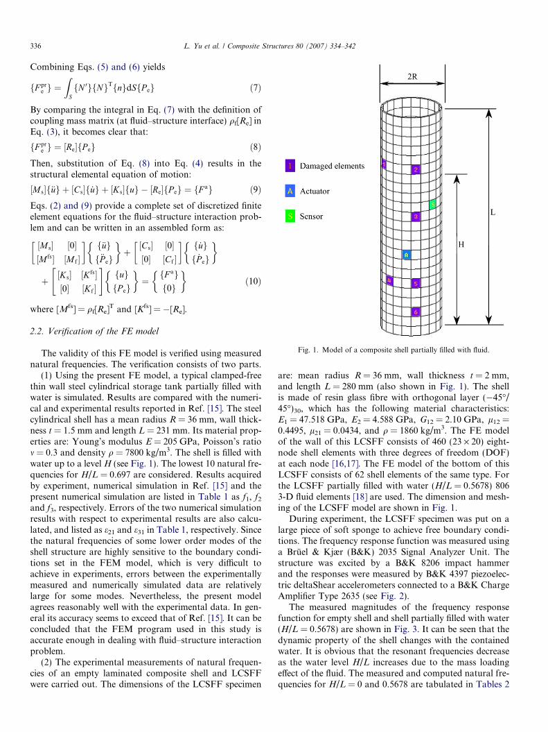
Fig. 1. Model of a composite shell partially filled with fluid.
336 L. Yu et al. / Composite Structures 80 (2007) 334–342
Combining Eqs. (5) and (6) yields
fF pre g ¼
ZSfN 0gfNgTfngdSfP eg ð7Þ
By comparing the integral in Eq. (7) with the definition ofcoupling mass matrix (at fluid–structure interface) qf[Re] inEq. (3), it becomes clear that:
fF pre g ¼ ½Re�fP eg ð8Þ
Then, substitution of Eq. (8) into Eq. (4) results in thestructural elemental equation of motion:
½M s�f€ug þ ½Cs�f _ug þ ½Ks�fug � ½Re�fP eg ¼ fF ag ð9ÞEqs. (2) and (9) provide a complete set of discretized finiteelement equations for the fluid–structure interaction prob-lem and can be written in an assembled form as:
½M s� ½0�½M fs� ½M f �
� � f€ugf€P eg
� �þ½Cs� ½0�½0� ½Cf �
� � f _ugf _P eg
� �
þ ½Ks� ½K fs�½0� ½K f �
" #fugfP eg
� �¼fF agf0g
� �ð10Þ
where [Mfs] = qf[Re]T and [Kfs] = �[Re].
2.2. Verification of the FE model
The validity of this FE model is verified using measurednatural frequencies. The verification consists of two parts.
(1) Using the present FE model, a typical clamped-freethin wall steel cylindrical storage tank partially filled withwater is simulated. Results are compared with the numeri-cal and experimental results reported in Ref. [15]. The steelcylindrical shell has a mean radius R = 36 mm, wall thick-ness t = 1.5 mm and length L = 231 mm. Its material prop-erties are: Young’s modulus E = 205 GPa, Poisson’s ratiom = 0.3 and density q = 7800 kg/m3. The shell is filled withwater up to a level H (see Fig. 1). The lowest 10 natural fre-quencies for H/L = 0.697 are considered. Results acquiredby experiment, numerical simulation in Ref. [15] and thepresent numerical simulation are listed in Table 1 as f1, f2
and f3, respectively. Errors of the two numerical simulationresults with respect to experimental results are also calcu-lated, and listed as e21 and e31 in Table 1, respectively. Sincethe natural frequencies of some lower order modes of theshell structure are highly sensitive to the boundary condi-tions set in the FEM model, which is very difficult toachieve in experiments, errors between the experimentallymeasured and numerically simulated data are relativelylarge for some modes. Nevertheless, the present modelagrees reasonably well with the experimental data. In gen-eral its accuracy seems to exceed that of Ref. [15]. It can beconcluded that the FEM program used in this study isaccurate enough in dealing with fluid–structure interactionproblem.
(2) The experimental measurements of natural frequen-cies of an empty laminated composite shell and LCSFFwere carried out. The dimensions of the LCSFF specimen
are: mean radius R = 36 mm, wall thickness t = 2 mm,and length L = 280 mm (also shown in Fig. 1). The shellis made of resin glass fibre with orthogonal layer (�45�/45�)30, which has the following material characteristics:E1 = 47.518 GPa, E2 = 4.588 GPa, G12 = 2.10 GPa, l12 =0.4495, l21 = 0.0434, and q = 1860 kg/m3. The FE modelof the wall of this LCSFF consists of 460 (23 · 20) eight-node shell elements with three degrees of freedom (DOF)at each node [16,17]. The FE model of the bottom of thisLCSFF consists of 62 shell elements of the same type. Forthe LCSFF partially filled with water (H/L = 0.5678) 8063-D fluid elements [18] are used. The dimension and mesh-ing of the LCSFF model are shown in Fig. 1.
During experiment, the LCSFF specimen was put on alarge piece of soft sponge to achieve free boundary condi-tions. The frequency response function was measured usinga Bruel & Kjær (B&K) 2035 Signal Analyzer Unit. Thestructure was excited by a B&K 8206 impact hammerand the responses were measured by B&K 4397 piezoelec-tric deltaShear accelerometers connected to a B&K ChargeAmplifier Type 2635 (see Fig. 2).
The measured magnitudes of the frequency responsefunction for empty shell and shell partially filled with water(H/L = 0.5678) are shown in Fig. 3. It can be seen that thedynamic property of the shell changes with the containedwater. It is obvious that the resonant frequencies decreaseas the water level H/L increases due to the mass loadingeffect of the fluid. The measured and computed natural fre-quencies for H/L = 0 and 0.5678 are tabulated in Tables 2

Table 1Natural frequencies of the cylindrical shell filled with water, H/L = 0.697
Experimental results [15],f1 (Hz)
FEM results [15],f2 (Hz)
e21 (%) f2�f1
f1
��� ���%� �FEM results using present model,f3 (Hz)
e31 (%) f3�f1
f1
��� ���%� �
522 543.1 4.042 525.43 0.657582 672.7 15.584 625.29 7.438798 806 1.003 802.45 0.558
1196 1188.4 0.635 1227.3 2.6171244 1253.2 0.740 1236.6 0.595– 1407.4 – 1297.7 –1394 1425.3 2.245 1456 4.4471546 1553.8 0.505 1538.7 0.472– 1679.7 – 1592 –
Brüel & Kjær (B&K) 2035 Signal Analyzer Unit
B&K Charge Amplifier Type 2635
B&K 4397 piezoelectric deltaShear accelerometers
B&K 8206 impact hammer
Sponge
Shell
Fig. 2. Schematic diagram of the experimental set-up for LCSFF.
0 200 400 600 800 1000 1200 1400 1600 18000
500
1000
1500empty shell
shell partialy filled with water(H/L=0.5678)
Acc
eler
atio
n F
RF
(m
m/s
²N)
Frequency (Hz)
Fig. 3. The measured frequency response function of the LCSFF with H/L = 0 and 0.5678.
Table 2Natural frequencies of the laminated composite cylindrical shell withH/L = 0
Experiment results (Hz) FEM results (Hz) Error (%)
638 640.48 0.37161006 1019.2 1.29511712 1795.6 4.66
Table 3Natural frequencies of the laminated composite cylindrical shell filled withwater with H/L = 0.5678
Experiment results (Hz) FEM results (Hz) Error (%)
422 424.84 0.668487728 734.92 0.941599954 984.72 3.119669
1336 1355.2 1.4167651380 1401.6 1.541096
L. Yu et al. / Composite Structures 80 (2007) 334–342 337
and 3, respectively. Since the LCSFF under investigation isaxially symmetrical, all natural frequencies listed in Tables2 and 3 are repeated natural frequencies, so only the oddnumber order ones are listed. Table 2 shows a maximumerror of 4.66% for the first six natural frequencies for theempty composite shell. Table 3 shows that the average
error is 1.537% and the maximum error is 3.12% for thefirst 10 natural frequencies of the LCSFF with water levelH/L = 0.5678. Therefore, the agreement between numeri-cal and experimental results is generally satisfactory. Theproposed FE model can provide enough accuracy in deal-ing with fluid contained structures made of compositematerials.
2.3. Mathematical formulation of piezoelectric sensors
and actuators
Embedded and/or surface mounted piezoelectric patchesare widely used in online damage detection due to theiradvantage in sensitivity, weight and volume. Based on pre-vious numerical [8] and experimental work [19,20], simula-tion on piezoelectric sensors and actuators in FE model isfeasible in numerical study of damage detection.
When piezoelectric patches are embedded into the com-posite shell as sensors and actuators, the direct and con-verse piezoelectric equations with respect to the referencecoordinate axes can be written as follows [21]
frPg ¼ ½QP�feg � ½e�TfEg ð11Þ
fDg ¼ ½e�feg þ ½�e�fEg ð12Þ

338 L. Yu et al. / Composite Structures 80 (2007) 334–342
where {rP} and [QP] are the stress vector and the trans-formed elastic stiffness matrix of the piezoelectric material,respectively; {e} the strain vector; {E} the electric field vec-tor; {D} the electric displacement vector; ½�e� the permittiv-ity matrix and [e]T the transpose of [e]. The piezoelectricstress coefficient matrix [e] is expressed in terms of thestrain coefficient matrix [d] as
½e� ¼ ½d�½QP� ð13ÞA thin piezoelectric patch, polarized only in the thick-
ness direction, exhibits transversely isotropic properties inthe plane perpendicular to the thickness direction. Eqs.(11) and (12) can then be written as
rx
ry
syz
szx
sxy
8>>>>>>><>>>>>>>:
9>>>>>>>=>>>>>>>;¼
QP11 QP12 0 0 0
QP21 QP22 0 0 0
0 0 QP44 0 0
0 0 0 QP55 0
0 0 0 0 QP66
266666664
377777775
ex
ey
cyz
czx
cxy
8>>>>>>><>>>>>>>:
9>>>>>>>=>>>>>>>;
þ ½QP�T
0 0 d31
0 0 d31
0 d15 0
d15 0 0
0 0 0
266666664
377777775
0
0
E3
8><>:
9>=>; ð14Þ
D1
D2
D3
8><>:
9>=>; ¼
0 0 0 d15 0
0 0 d15 0 0
d31 d31 0 0 0
264
375½QP�
ex
ey
cyz
czx
cxy
8>>>>>>><>>>>>>>:
9>>>>>>>=>>>>>>>;
þ�e11 0 0
0 �e22 0
0 0 �e33
264
375
0
0
E3
8><>:
9>=>; ð15Þ
where E3 is the electric field intensity exerted on piezoelec-tric materials in the thickness direction, and can be ex-pressed as
E3 ¼V 3ðtÞ
tp
ð16Þ
where V3(t) is the applied voltage and tp is the thickness ofthe piezoelectric actuator.
3. Detection of structural crack damage
3.1. Crack damage and its effect on the stiffness of acomposite structure
In the FE model, the crack damage is simulated by mod-ifying the elastic moduli of the damaged element. For com-
posite materials with crack damages, variations of localelastic modulus can be calculated as follows [22]
E1 ¼ E01 þ 2x3ðC3 þ C6ðl0
12Þ2 � C12l0
12ÞE2 ¼ E0
2 þ 2x3ðC6 þ C3ðl021Þ
2 � C12l021Þ
l12 ¼ l012 þ x3
1�l012
l021
E02
ðC12 � 2C6l012Þ
l21 ¼ E2
E1l12; l12 � l21
G12 ¼ E2
2ð1þl12Þ; G23 ¼ G13 ¼ G12
9>>>>>>>>=>>>>>>>>;
ð17Þ
where E1, E2, l12, l21 and G12 are the elastic moduli, Pois-son’s ratios and shear modulus of the thin wall compositeshell with crack damage, respectively. E0
1, E02, l0
12, l012 and
G012 are the elastic moduli, Poisson’s ratios and shear mod-
ulus of the intact composite structure, respectively. C1–C12
are material coefficients independent of strains and dam-age, but dependent on the composite configuration, i.e., fi-bre geometry and orientations, fibre volume fraction, plystacking sequence, etc. These parameters can be deter-mined by measuring the specimen made of the same com-posite materials [22]. Let x3 be a variable representingthe crack damage status, which is related to the number,length and width of the crack. It can be expressed as
x3 ¼ gc�ac�bc
�f c ð18Þwhere gc is the crack density, which is defined as the cracknumber in a unit area; �ac and �bc are the average length andwidth of the crack, respectively, and �f c is an adjustmentcoefficient, which has been discussed in Ref. [22].
For other types of damage in a resin glass fibre struc-ture, such as delamination, the variations of local elasticmodulus can also be calculated using Eq. (17) with its cor-responding material coefficients.
3.2. Index of damage
Generally speaking, changes in structural dynamic prop-erties due to structural damage are very small. Yan andYam [8] pointed out that when the crack length in a com-posite plate reached 1% of the plate length, the relative var-iation of the structural natural frequencies was generallyabout 0.01–0.1%. Therefore, using vibration modal param-eters, e.g., natural frequencies, displacement or strain modeshapes, and modal damping factors is generally ineffectivein identifying small and incipient structural damage. Therevelation of small and incipient damage in in-service struc-tures has important applied values, because it can monitorthe occurrence and development of structural damage.Therefore, a sensitive indicator needs to be found to showthe change of the response data caused by damage. Chui[23] pointed out that the local singularity in a time-sequence signal could be more clearly exhibited if the signalis decomposed using wavelet transform. This idea has beensuccessfully applied to vibration-based structural damagedetection in many works [8,20,24–26]. When structuralvibration response signals in time domain are decomposedinto multiple sub-signals using wavelet transform, the

L. Yu et al. / Composite Structures 80 (2007) 334–342 339
change in each sub-signal corresponding to structural dam-age may manifest notable difference. The percentagechange of energy spectra between the intact and damagedstructures is therefore taken as the feature index of struc-tural damage. It has been observed that the energy spec-trum of the decomposed wavelet signal obtained fromstructural vibration responses can indicate the structuraldamage status with higher sensitivity. Even the ratio ofthe damage size to the total structural size retreats to theorder of 0.01–0.1%, the structural damage can still bedetected using energy spectrum variation obtained bywavelet analysis [8]. So in the present study, the variationof the energy spectrum of decomposed wavelet signal isused as the index of damage.
The wavelet transform of a continuous vibrationresponse x(t) is defined as
W xða; bÞ ¼ ðjajÞ�12
ZR
xðtÞW� t � ba
dt ð19Þ
where b is the translation parameter; a the scale parameter;x(t) the vibration response to be decomposed; W*(t) thetransforming function (mother wavelet); and Wx the calcu-lated wavelet coefficients, which can be used to recomposethe original function x(t). The recomposed equation forx(t) can be expressed as
xðtÞ ¼ 1
CW
Z þ1
�1
Z þ1
�1
1
a2W xða; bÞW
t � ba
dadb ð20Þ
where CW ¼ 2pRþ1
0ðjWðrÞjÞ2dr=r.
Fig. 4. Damage indices for the same dama
Various forms of wavelet base function W(t) have beendeveloped. One of the most useful practical methods forsignal decomposition is the wavelet packet analysis(WPA) [27]. The WPA algorithm is as follows:
Let gnj ðtÞ 2 Un
j , then gnj ðtÞ can be expressed as
gnj ðtÞ ¼
Xl
dj;nl unð2jt � lÞ ð21Þ
In WPA decomposition algorithm, fdj;2nl g and fdj;2nþ1
l g canbe calculated as follows:
dj;2nl ¼
Pk
ak�2ldjþ1;nk
dj;2nþ1l ¼
Pk
bk�2ldjþ1;nk
9>=>; ð22Þ
and the formula for recomposing fdjþ1;nl g using fdj;2n
l g andfdj;2nþ1
l g is
djþ1;nl ¼
Xk
hl�2kdj;2nk þ gl�2kdj;2nþ1
k
� �ð23Þ
The WPA method can adaptively choose the corre-sponding frequency bandwidth according to the character-istics of the signal to be analyzed, and the decomposedsub-wavelet functions possess orthogonality in bothfrequency and time domains.
Assuming that the original vibration response xðiÞ0;0ðtÞ atthe ith measurement location of a structure is decomposedinto xðiÞL;jðtÞ ðj ¼ 1; 2; . . . ; 2L�1Þ, with L being the selectedlayer number of the wavelet tree, xðiÞ0;0ðtÞ can then beexpressed as
ge with different water surface levels.

340 L. Yu et al. / Composite Structures 80 (2007) 334–342
xðiÞ0;0ðtÞ ¼X2L�1
j¼1
xðiÞL;jðtÞ ð24Þ
Let the energy of the jth order sub-signals of the intactand damaged structures be U 0
L;j and U dL;j, respectively. A
non-dimensional damage feature index vector can be com-posed as follows:
V d ¼ fv1; v2; . . . ; v2L�1gT
¼ 1�U d
L;1
U 0L;1
; 1�U d
L;2
U 0L;2
; . . . ; 1�U d
L;2L�1
U 0L;2L�1
( )T
ð25Þ
Generally, different structural damage types, locationsand severities will match one by one with different damagefeature index vectors. Therefore, the element values of dif-ferent damage feature index vector Vd can not only showthe differences between the intact and damaged structures,but also indicate the changes of different structural damagestatus.
...……
….
..……
…..
Layer number of crack location
Crack length value
Input layer with 32 nodes
Hidden layer with 16 nodes
Output layer with 3nodes
Tan-Sigmoid Transfer Function
Liner Transfer Function
Circumferential number in the determined layer of crack location
Fig. 5. Structure of a BP neural network for identification of crack lengthand location.
Fig. 6. The error of BP neural network in the training process.
4. Damage index and damage identification of LCSFF by
ANN
4.1. Damage index for LCSFF
In this study the damage indices are expressed in termsof the percentage changes in the energy spectrum of thedecomposed wavelet signals of structural dynamic responsedue to damage. There is a crack in the LCSFF model witha length �ac ¼ 3 mm and a width �bc ¼ 0:1 mm at location 6as shown in Fig. 1. For this damaged shell the damage indi-ces measured for twelve gradually increasing water surfacelevels in the shell from H/L = 0 (empty shell) to H/L = 1(fully-filled) are shown in Fig. 4. It can be seen that mostof the water-contained shells have larger damage index val-ues than the empty shell. Therefore, compared with theempty shell, the presence of fluid in the structure doesnot reduce the sensitivity of the damage index.
It should also be noted that the locations of the sensorsand actuators are important for damage detection. Forshell with water lever 3, the absolute value of the damageindex is relatively small and is less than 10%, while itreaches more than 500% for water lever 7. This suggeststhat an optimization on the locations of sensors and actu-ators is worthy of further study.
4.2. Identification of structural damage status by ANN
As an example, one ANN for LCSFF with H/L = 0.5678 is designed and trained. The vibrationresponses of 321 different cases are numerically simulatedusing FEM, and in all these cases, H/L = 0.5678. These321 cases include an intact LCSFF, LCSFFs with crackdamage at 80 different locations of the shell, each with fourdifferent crack lengths (1–8% of the LCSFF height). Then,damage indices of these 320 damage cases are obtained by
comparing the energy spectrum of the decomposed waveletsignals for each case with that of the intact structure. Fromthese damage cases, six cases are selected as verificationsamples, with their locations shown in Fig. 1. The other314 damage cases are used as train samples. The mesh inpresent FE model is regular. Then the elements in the shellcan be located by its row and column number. The rownumber is counted from top to bottom of the model. Thecolumn number is counted clockwise and the column con-taining the sensor is selected as the first column. The rowand column number are unified by dividing them by 23(the total row number) and 20 (the total column number),respectively. The lengths of the cracks are expressed in per-millage of the LCSFF height. One back propagation (BP)neural network, possessing 32 inputs, one hidden layer with16 nodes and three outputs, is designed (Fig. 5). The inputsare 32 elements of the damage index, and the outputs arethe row and column number of the damaged element,and the length of the crack. After trained with 314 samplesfor 1142 epochs, the performance goal is achieved (Fig. 6).

Table 4Identification of crack damage using the trained ANN (crack location and length)
Case 1 Case 2 Case 3 Case 4 Case 5 Case 6
Row number of damage element (real) 6.000 6.000 11.000 18.000 18.000 21.000Row number of damage element detected by ANN 6.088 6.054 11.222 18.382 18.215 21.171Column number of damage element (real) 6 2 2 5 2 2Column number of damage element detected by ANN 5.879 2.037 1.991 4.923 2.026 1.971Crack length value (real) (%) 2.000 7.000 8.000 3.000 6.000 8.000Crack length value detected by ANN (%) 2.014 7.031 8.152 3.044 5.988 8.119
L. Yu et al. / Composite Structures 80 (2007) 334–342 341
Results for six sets of verification samples obtained bynumerical simulation using FEM are listed in Table 4.(The row and column numbers listed in Table 4 are con-verted to their actual values by multiplying them by thetotal numbers of row and column, respectively. The lengthsof cracks listed in Table 4 are converted to percentage ofthe LCSFF height.) It shows that the identified crack statusis very close to the actual crack status.
5. Conclusions
In this paper a dynamic FE model of LCSFF is estab-lished by considering the interaction between fluid andthe composite shell. Two piezoelectric patches embeddedinto the composite shell, one serving as an actuator andthe other as a sensor, are included in the FE model forobtaining the numerically simulated structural dynamicresponses. The advanced composite damage mechanics isused to simulate the crack, and the change in energy spec-trum of the decomposed wavelet signals of structuraldynamic responses is used as the damage index due to itshigh sensitivity to structural damage. The reliability ofthe model is verified using the experimentally measuredstructural natural frequencies. Effects of fluid containedin the composite vessel on structural damage index areinvestigated. Damage detection using a BP neural networkfor a LCSFF with H/L = 0.5678 is successfully carried out.It shows that the general approach proposed in this paper,including the use of smart elements, damage index and theANN, provides an effective tool for LCSFF damage detec-tion applications.
Acknowledgements
The authors would like to thank for the support by theResearch Grants Council of Hong Kong Special Adminis-trative Region of China under the Project No. PolyU 5313/03E; and Natural Science Foundation of China under thegrant 50375123. The second author wishes to acknowledgethe support from a special fund for recently promotedChair Professors given by The Hong Kong PolytechnicUniversity.
References
[1] Carden PE, Fanning P. Vibration based condition monitoring: areview. Struct Health Monit 2004;3(4):355–77.
[2] Shu XP. A generalised model of laminated composite plates withinterfacial damage. Compos Struct 2006;74:237–46.
[3] Boutaous A, Peseux B, Gornet L, et al. A new modeling of plasticitycoupled with the damage and identification for carbon fibrecomposite laminates. Compos Struct 2006;74:1–9.
[4] Yan YJ, Yam LH, Cheng L, Yu L. FEM modeling method ofdamage structures for structural damage detection. Comput Struct2006;72:193–9.
[5] Zou Y, Tong L, Steven GP. Vibration-based model-dependentdamage (delamination) identification and health monitoring forcomposite structures – a review. J Sound Vib 2000;230:357–78.
[6] Araujo dos Santos JV, Mota Soares CM, Mota Soares CA, MaiaNMM. Structural damage identification in laminated structures usingFRF data. Compos Struct 2005;67:239–49.
[7] Meo M, Zumpano G. Nonlinear elastic wave spectroscopy identifi-cation of impact damage on a sandwich plate. Compos Struct2005;71:469–74.
[8] Yan YJ, Yam LH. Online detection of crack damage in compositeplates using embedded piezoelectric actuators/sensors and waveletanalysis. Compos Struct 2002;58:29–38.
[9] Chen Q, Chan YW, Worden K. Structural fault diagnosis andisolation using neural networks based on response-only data. ComputStruct 2003;81:2165–72.
[10] Pierce SG, Worden K, Manson G. A novel information-gaptechnique to assess reliability of neural network-based damagedetection. J Sound Vib 2006;293:96–111.
[11] Kang YL, Lin XH, Qin QH. Inverse/genetic method and itsapplication in identification of mechanical parameters of interfacein composite. Comput Struct 2004;66:449–58.
[12] Staszewski WJ. Intelligent signal processing for damage detection incomposite materials. Compos Sci Technol 2002;62:941–50.
[13] Su ZQ, Ye L. Lamb wave-based quantitative identification ofdelamination in CF/EP composite structures using artificial neuralalgorithm. Compos Struct 2004;66:627–37.
[14] Krishnamurthy KS, Mahajan P, Mittal RK. Impact response anddamage in laminated composite cylindrical shells. Compos Struct2003;59:15–36.
[15] Mazuch T, Horacek J, Trnka J, Vesely J. Natural modes andfrequencies of a thin clamped-free steel cylindrical storage tankpartially filled with water: FEM and measurement. J Sound Vib1996;193:669–90.
[16] Fenves SJ. Numerical and computer methods in structural mechan-ics. New York: Academic Press, Inc.; 1973.
[17] Taylor RL, Beresford PJ, Wilson EL. A non-conforming element forstress analysis. Int J Numer Methods Eng 1976;10:1211–9.
[18] Mazuch T. Determining the acoustic natural modes and frequenciesof irregular shaped rigid walled cavities by FEM. J Czech SlovakMech Eng 1993;44:433–40.
[19] Banks HT, Inman DJ, Leo DJ, Wang Y. An experimentally validateddamage detection theory in smart structures. J Sound Vib 1996;191:859–80.
[20] Yam LH, Yan YJ, Jiang JS. Vibration-based damage detection forcomposite structures using wavelet transform and neural networkidentification. Compos Struct 2003;60:403–12.
[21] Rosen CZ. Piezoelectricity. New York: American Institute of Phys-ics; 1992.

342 L. Yu et al. / Composite Structures 80 (2007) 334–342
[22] Talreja R. Damage mechanics of composite materials. Compositematerials series, vol. 9. Amsterdam: Elsevier; 1994.
[23] Chui CK. Wavelets: a mathematical tool for signal processing. Phil-adelphia, PA: Society for Industrial and Applied Mathematics; 1997.
[24] Liew KM, Wang Q. Application of wavelet theory for crackidentification in structures. J Eng Mech 1998;124(2):152–7.
[25] Hou Z, Noori M, Amand RSt. Wavelet-based approach for structuraldamage detection. J Eng Mech ASCE 2000;126:677–83.
[26] Lu C, Hsu Y. Vibration analysis of an inhomogeneous string fordamage detection by wavelet transform. Int J Mech Sci 2002;44:745–754.
[27] Jones CL, Lonergan GT, Mainwaring DE. Wavelet packetcomputation of the Hurst exponent. J Phys A: Math Gen 1996;29:2509–27.


![Discrepancies Between Free Vibration of FML and Composite ... › article_3773_60f53b5298b... · cally cylindrical shells [3- 12]. Zhang [13] obtained the natural frequencies of laminated](https://img.pdfslide.net/doc/110x75/5f0441ba7e708231d40d14d2/discrepancies-between-free-vibration-of-fml-and-composite-a-article377360f53b5298b.jpg)