Embed Size (px)
Citation preview

©

©
INIT.
I-ADA E
APRIL 2010
REVISION
aBRIENEi DEREENGINEERS INC.
NOT TO SCALE
2010 © O'Brien and Cere Engineers. Inc.
PROCESS AND INSTRUMENTATION
DP 11 FOR NYSDEC AND COUNTY REVIEW
DP 111 INTERNAL REVIEW
DP 112 DRAFT FOR HONEYWELL REVIEW
DP 111 DRAFT FOR HONEYWELL REVIEW
LEGEND & S~'MBOLS
Flash Mix
HONEYWELL INTERNATIONAL, INC.DP #'
WATER TREATMENT PLANTTOWN OF CAMILLUS, NEW YORK
Filter Feed
Subsystem
Plant Water
Flocculation
Clarification
Mscellaneous
Distribution Box
GAC Adsorption
Compressed Ai r
Effluent MJnitoring
MJltimedia Fi Itration
pH Adjustment (Fine)
pH Adj ustment (Rough)
Aluminum Sulfate (Alum)
Sodium Hydroxide (Caustic)
Sludge Holding and Transfer
B 2/12/10C 3/10/10o 4/9/10
A 2/4/10
SulfuricAcid and Bulk Unloading
DESIGNED BY__ CHECKED BY __
IN CHARGE OF _
NO. DATE
....--------------.,,...- .._---....~---- -FIL~ NO.
11 ?3.4561 3-1A
Letter designation of equipment, may be fewer or
more than 3letters (e.g., T indicates tank). Refer to
the Lead Sheets for list of letterdesignations for
equipment.
Subsystem number, two digits (e.g., 03 indicates
FI ash Mxing). Refer to the Lead Sheets for Ii st of
numerical designations for subsystems.
Additional categorization, where required, for
dupl icate items (e.g., MX-030lC would indicate the
mixer is the third identical unit within the first Flash
MxingTank). This letterwill be left blank if there is
only one mixer in the tank.
Sequential numbering for identical equipment
items, two digits (e.g., 01 indicates the equipment or
tank is the fi rst of one or more identical units).
09
08
02
04
05
01
07
03
06
17
14
15
10
16
12
13
11
Subsystem
Number
yy
xx
Equi pment T~~f\Jumberi n~:
***-XXfYA, where:
A, B,C,or
D,etc.
4/09/10
PREUMINARYNOT FOR
CONSTRUcnONDATE:
IT IS A VIOLATION Of LAW FORNff PERSON, UNLESS ACTlNG UNDERTHE DIRECTION Of A LICENSED ENGINEER, TO ALTER THIS DOCUMENT.
THIS DRAWING WAS PREPARED ATTHE SCAlE INDICATED IN THE nrLEBLOCK. INACCURACIES IN THE STATEDSCALE MAY BE INTRODUCED WHENDRAWINGS ARE REPRODUCED BY At((MEANS. USE THE GRAPHIC SCALE BARIN THE TITLE BLOCK TO DETERMINETHE ACTUAl SCALE Of THIS DRAWING.
LETTER DESlGNAlION OF EOUPMENT
ARV - AUTOMATIC AIR RELIEF VALVE
BPV - BACK PRESSURE VALVE
CKV - CHECK VALVE
HV - HAND VALVE
FOol - flOW CONTROL VALVE
FV - FLOW VALVE
LOoI - LEVEL CONTROL VALVE
PRV - PRESSURE REDUCING VALVE
PSV - PRESSURE RELIEF VAlVE
lCV - TEMPERATURE CONTROL VALVE
VRV - VACUUM RELIEF VAlVE
T - TANK
TB - TOTE
TD - ELECTRIC HOIST
TK - PROCESS VESSEL
TZ - DIESEL GENERATOR
VGAC - VAPOR PHASECARBON UNIT
W - ROLLOFF WINCH
X - FUME HOOD
ZZ - LAB INSTRUMENTS
SP - COMPOSITE SAMPLER
ST - AIR STRIPPER
STI - STEAM IN.IECTOR
AG - AGITATOR
BL - BLOWER I FAN
CE - CENTRIFUGE
CF - CHEMiCAl FEED UNIT
CMP - COMPRESSOR
CV - CHEMiCAl VESSEL
o - SCRUBBER
DE - DECANTER
FP - FILTER PRESS
GAC - GRANULAR ACTNATED CARBONVESSEL .
GR - GRINDER
HP - HYDRAULIC PUMP
IE - ION EXCHANGE
IPC - INCLINED PLATE CLARIFIER
LGAC - L1Q. PHASE GRANULARACTIVATED CARBON UNITS
MH - MAINTENANCE SHOP HAND HOIST
MIX - MIXER
MMF - MULTIMEDIA FILTER VESSEL
PB - POLYMER BLENDING
PLF - PRESSURE LEAF FILTER
PM - PIPING MANIFOLD
PU - PUMP
R - REACTOR
RTO - REGENERATIVE THERMAL OXIDIZER
SK - SPRAY COOLER
SI - SILENCER
SM - STATIC MIXER
SAMPLE COOLER
HAMMER ARRESTOR
SPRAY NOZZLE
DETONATION FLAMEARRESTER
WEATHER CAP
FLAME ARRESTOR
WEATHER CAP
EXHAUST HEAD
CARTRIDGE FILTER
BREATHER CAP
MIXING TEE
MOTOR
THERMOSTATIC STEAM TRAP
THERMODYNAMIC STEAM TRAPt----------------tLET1ER DESIGNATION or VALVES
BASKET STRAINER
CONE STRAINER
FLAT PLATE STRAINER
SUMP STRAINER
FILTER
REMOVABLE SPOOl..
SWING ELBOW
EXPANSION JOINT
STIWNG WELL WITHPROBE INSERT
TWIN BASKET STRAINER
T STRAINER
Y STRAINER
VACUUM BREAKER
DRESSER COUPLING
FLEXIBLE HOSE
STEAM TRAP ASSEMBLYSTAINLESS STEEL
SAMPLE PROBE
STEAM TRAP
INVERTED BUCKET STEAM TRAP
STEAM TRAP ASSEMBLYINCLUDING STRAINER, BLOCKVALVES AND BYPASS WITHVALVE CARBON STEEL
IMPULSE STEAM TRAP
GENERC COMPONENT
STATIC MIXER
INSULATED
SECONDARYCONTAINMENT
INSULATED, HEAT TRACED
PPN: SEGMENT lABELS
ffiJI~I
6
ROTARY POSITIVEDISPLACEMENT BLOWER
AIR OPERATEDolAPHRAM(AOD) PUMP
PROCESS VESSEL(NON-PRESSURIZED)
PROCESS VESSEL(PRESSURIZED)
EJECTOR/EDUCTOR
ROTARY LOBE PUMP
PERISTALTIC PUMP
FUm SYSTEM TEMPERATUREREGUlATOR
SELF CONTAINED PRESSUREREDUCING REGULATOR
PRESSURE REDUCING REGULATORWIJH NTEGIW. OUTLET PRESSURERDJEF V~VE
SELf CONTAINED BACKPRESSUREREGUlATOR
LEVEL REGULATOR WITHMECHANICAL LINKAGE
INSTRUMENT AIR SUPPLYWI1H REGULATOR
PRESSURE REDUCING REGULATORWITH EXTERNAL TAP
~PRESSURE REGULATORWITH EXTERNAL TAP
DIFFERENTIAl.. PRESSUREREDUCING REGULATOR WITHINTERNAL. AND EXTERNAl.. TAPS
ON/OFF FLOW CONTROL VALVE(PNEUMATIC ACT. wi SPRINGREruRN)
ON/OfF flOW CONTROL VALVE(El£CTRIC ACT. w/ SPRINGRETURN)
ANGlE PRESSURE RELIEF VALVE
STRAIGHT- THRU PRESSURE RELIEfVAlVE OR CONSERVATION VENT
PRESSURE AND VACUUM RELIEFMANHOLE COVER
PRESSURE RELIEF RUPTURE DISK
VACUUM RELIEF RUPTURE DISK
TEMPERATURE FUSIBLE PLUG ORDISK
CGfIIIJL .\!S AND REGWlORS 0
~~
~[0
~
CD~
LS:l
iji
•
I-
____ CONNECTION TO PROCESS c::::l
~ :UARY TUBE a=D---------- El.£CTRIC c:(p~PNElJt.tATIC ~
--t:--r-- HYDRAULIC
~ 50nwARE OR Di'TA UNK FZl--- MECHANICAl.. LINK L...=:J
L VACUUM RELIEF VALVE OR~ CONSERVATION VENT
-+- ~::URE AND VACUUM RELIEF
I I ~..... ----' SPILL TRAY
I----------t ASlCM.IJtES ~ ~
SPECMUIY
DOUBLE SEAL, FlUSHlIQUID FROM LOCALCONTAINER
CENTRiFUGAl PUMP
CENTRIFUGAl FAN
DIAPHRAGM or- TUBUlARMETERING PU~I?
I ~~G~I~E~~~CAL SEAL,
I ~A~~~G~~U~~ LIQUIDFROM PUMP DISCHARGE
I ~A~~G~~~:NAlFLUSH LIQUID
I ~~Lh~~~~~FLUSH LIQUID
I ~~Lh~~~~~FROM PUMP DISCHARGE
I SEAL-LESS PUMP
I
I ~~~i5RS~F~:ESSURECONVECTION COOLER
I DRY SEAL
EJECTOR
CAliBRATION TUBE
CHEMICAL SEAL
FILTER/REGULATOR/GAUGE
STEAM TRAP
PULSATION DAMPENER
SNUBBER
FILTER
WEATHER CAP
EXPANSION JOINT
Y STRAINER
DRAIN
MUFFLER
H FlANGE
I:I ORIFICE FlANGE
III FIX UNION
I Bl:JND FlANGE
7 OPEN SPECTACLE BLANK
V CLOSE SPECTACLE BLANK
Y SPACER
T PADDLE BlANK
>Cl
o PLUG
-3 CAP
D CONCENTRIC REDUCER
D ECCENTRIC REDUCER(FlAT ON TOP)
-;: HOSE CONNECTION
-n TRIClAMP STERILE CONNECTION
-t-{l INGOLD CONNECTION w/TRIClAMP
>- SUP ON HOSE CONNECTION
~ 8"YONET CONNEcnON FORTUBING
I'YNtI FLEX CONNECTOR
CXI QUICK CONNECTION
....I.... ClEANOUT= HARNESSED COUPLING
IDmE4
IUlYPEJ
lulYPE&
IUlYPE7
I aTm1
IDmE2
I aJlllEt
I amES
SODIUM HYDROXIDE SOL'N
ANTIFOAM
AERATION AIR
BACKWASH WASTE
CONDENSATE, 125 PSIG
NATURAL GAS
DRAIN
FERMENTATION AIR
DIATOMACEOUS EARTH
DEIONIZED WATER
FIRE WATER
GROUND WATER
PROCESS
PLANT AIR
PROCESS CHEMICAL
PROCESS VACUUM
STEAM, 40 PSIG
STERILE AIR
SANITARY SEWER
SEQUESTERING AGENT
SEAL FLUID
SCRUBBER UQUOR
POLYMER (ANIONIC)
POLYMER (CATIONIC)
PROCESS SEWER
SOLVENT
STORM WATER
UREA
VAPOR ORGANIC COMPOUNDS
- PLANT WATER
PIPING FUJI) CODE DESlGMTIONS
AIR - ATMOSPHERIC AIR
AF
PC
CSO - CONDENSATE, 50 PSIG
DIW
DNAPL - DENSE NON-AQUEOUSPHASE UQUID
NAOH -
P -
OR
FA
LNAPl - LIGHT NON-AQUEOUSPHASE LIQUID
MACT - MACT REGULATED WW
MICRO - MICRONUTRIENT
N2G.-L - NITROGEN GAS. UOUID
NaOCL - SODIUM HYPOCHLORITE
PA
POLY C-
FlLTR - BFP FILTRATE/FLOOR SUMP
H202 - HYDROGEN PEROXIDE
H2S04 - SULFURIC ACID
HYO - HYDRAULIC FlUID
IA - INSTRUMENT AIR
PW
POLY A-
SLUDGE - SLUDGE
RF - REFRIGERENT
S125 - STEAM. 125 PSIG
PHOS - PHOSPHORIC ACID
POLY - POLYMER
VT
PS -
PV -
SOL
SW
UR
voc
ArMOS AT AMB
420# AT 2S<TF
300# AT 550"F
AT 3sar
300# AT 550°F
SCHED 20
SCHED 10
90# AT 7:fF
1501 AT 35<TF
TBD
100# AT 10<TF
1000# AT lSO"F
75# AT 7:fF
1501 ANSI B16.S FW
125# ANSI B16.1 GW
150# AT JOO"F
150# ANSI Bl6.5AT -320"F THRU120"F
125# AT 25<TF
SHEETMETALDUCllNG
150# AT (-)l00"F 540
150# ANSI B16.5 SAAT -20"F THRU100"F SAN
150# AT (-)300"F SEQ
SF
SL
PIPING SYMBOLS
PACKAGE
AL6XN TBD
C4
SSl
SS3
SS2
CSS
CS6
CS7
CI
CSl
CS2
CS3
CS4
SS4
SS5
GS
FRP 150# AT loaF
FRP2 ±" TBD WC
PTFE
SS6
SS7
IT
PlPINC SEQtENT lJBELS
'------- FLUID CODE
ALLOY
CS
CS
CS
304L sISTUBING
COPPERTUBING(TYPE K)
CAST IRON
CS
CS
CS
CS
SCH80 PVC PVC
304 SIS
304 SIS
SCH80 CPVC CPVC 100# AT 100°F
DUCTILE IRON 01 ATMOS AT 7S0F
POLYETHYLENE PETUBING
316L SISTUBING
316L SiSTUBING
316L SIS
316 SIS
PTFE LINED
FRP PIPE
FRP DUCTw/ LINER
GALVANIZEDSTEEL
316L sis SS8CORE W/VACINSULAll0N &304 SS JACKET
316 SIS CS SS9
.MAIE.B.JAI.~ PRESSURE RANGE
TEFLONTUBING
SCHED 80 PVC PYCSO
HOPE DR 32.5 HOPE
THIO - SODIUM THIOSULFATE
TRWW - TREATED WASTEWATER
TWS.-R- TOWER WATER SUPPLY.-t---INStU--i11QN--PlJIIOSE-----OESIGM------;ra.s-------I RETURN
IC - COLD CONSERVAnON/ANTlSWEAT
HC - HEAT CONSERVAnON
IP - PERSONAL PROTEcnON
OFF-DRAWINGDRAIN CONNECTOR
NEW PIPING
EXISTING PIPING
SECONDARY HOSE '-X~'1-~~ HEAT TRACINGINSULATION PURPOSE BA -
OFF-DRAWINGPIPING CONNECTOR . MATERiAl SPECIFICATION BW -
----- LINE NUMBER C125 -
OFF-DRAWINGUTIUTY CONNECTOR
I '-------- LINE SIZE (IN INCHES) CH4
TIE-IN POINT CHS,-R- HVAC CHILLED WATER
PIPING AND/OR BCu.DfRY lIES SUPPLY, RETURN, 42"F
EQUIPMENT TO BE t----------------I CNTC - CONTAMINATED CONDENSATEREMOVED
INDICATES SCOPE COAG - COAGULANT- .. - .. - SYSTEM BOUNDARY
~~~~N~~ CS - CLEAN STEAMSUB-CONTRACTOR t- V_E_N_OO_R "'1 DE
fIllING
VALe
PH: lie
3-WAY SUDE VAlVE
GATE VALVE
EXTENDED BODY GATE VAlVE
VENT/DRAIN GATE V~VE
SUDE VAlVE
KNIFE GATE VAlVE
BlANK GATE VAlVE
BUTTERFLY VAlVE
Y GlOBE VALVE
3-WAY GLOBE VAlVE
NEEDLE VALVE
HOSE Vt-J...VE
ANGLE HOSE VAlVE
BAll. V~VE
3-WAY 8AJ..L VALVE
ANGLE BLOWDOWN V~VE
8Al..ANCING Vt-J...VE
Y 8l..OWDOWN Vt-J...VE
TANK DRAIN VALVE
PLUG VALVE
3-WAY PLUG VN...Vf..
4-WAY PLUG V~VE
GLOBE VALVE
ANGLE GLOBE VALVE
DIAPHRAGM VALVE
PINCH Vt-J...VE
CHECK VALVE
WAFER CHECK Vt-J...VE
ANGLE CHECK VALVE
STOP CHECK VN...VE
ANGLE STOP CHECK VALVE
PUlSATION DANPENERS
J-WAY VALVE
4-WAY VALVE
EXCESS FLOW VN...Vf..
Y STOP CHECK V~VE
BACI<FLOW PREVENTER
AUTOMATIC RECIRCULATIONVALVE
MULTIVANE DAMPER ORLOUVER VALVE
SINGLE DAMPER ORLOUVER VALVE
ANGLE V~VE
I FL CODE II P&ID I
FLUID DESTINATIONICO~. PetiD NO. >(COL., ROW ONCONN. P&ID)
I FL CODE II P&ID I
~
~I~'\/
~ FLOAT VALVE
~SV
j 1 SV CONSERVAnON1 r BREATHER VENT
a.<,
Eo
CO~oI
oaN
La.<
I
oaN
VENT
1---__--INE-7II-~--~---------...~--------t WAS - WASTE ACTIVATED SLUDGE ~rr~ 1- ~I--'''' DOMESTIC WATER ~
ST - STEAM TRACING WD.-CW- SUPPLY.-RETURN
ET - ELECTRIC TRACING WDH - HOT DOMESTIC WATER -ElF"CT - COLD FLUID TRACING WFI _ WATER FOR INJECTION
FLAPPER VALVE
DIAPHRAGM AIR REL~-ASE JK - JACKETED PIPE WFiS - PURE STEAM
VALVE WP - PROCESS WATER 0- I El.AST GATE WPH - HOT PROCESS WATER II Q AUTOMATIC AIR RELIEF WPUR - PURIFIED WATER MIXER OR FlOCCULATOR... WITH ELECTRIC MOTOR~ VALVE WW _ WASTE WATER DRAWN BY _-:;; L- ." ...- .. ---..---------"------------------,---------------------....-----------....-,----....----....
Eo
<0...o

oa<'II
'a.<
SYMBOLS LETTER IDENTIFICATION OF INSTRUME~JTS
IN-IJtE INSTRUIe{TS tGRUMENT COI.PONENT LABELS INS1'RUMENT COIfI()fDl' lJ.BELS INSTRt ':'81' IlENTFICATION FIRST LElTER SUCCEEDIG LETTERS
@I 0 CONVERTS ELECRICAI..MEASURED OR MODIFIER READOUT OR OUTPUT MODIFIER
: ORIFICE PLATt: xxx ' BAlLOON WITH TAG NUMBER INPUT TO PNEuMATIC PIC - XXX YY AINITIATING VARIABLE PK"SIVE FUNCTION FUNCTION
~ ORIFICE PLAT~ IN QUICK CO ~- TTL sumx If REQUIRED
A ANAlYSIS AlARM
CHANGE FITTING EXISTINGLEVEL SWITCH {FLOAT lYPE) _ SEQUENTIAl No. B BURNER. COMBUSTION U'1ER'S CHOICE USER'S CHOICE USER'S CHOICE
[:::J FLOW NOZZLE ON P&ID C USER'S CHOICE CONTROL
c:=:JT TOP MOUNTED ACCESSORY
@ No. OF P&ID ON 0 USER'S CHOICE DIFFERENTIAlVENTURI TUBE
~ SIDE MOUNTED ACCESSORY POSITION SWITCH WHICH INSTRUMENT E VOLTAGE SENSOR (PRIMARY
~ SINGLE PORT PITOT TUBE~ § APPEARS ElEMENT)DIAPHRAGM ACTUATOR POSITION SWITCH CLOSED MEASURED VARIABLE
~ PITOT-VENTURI TUBE E( @ AND INSTRUMENT F FLOW RATE RATIO (FRACTION)PRESSURE-BAlANCED POSITION SWITCH OPEN FUNCTIONDIAPHRAGM ACTUATOR G USER'S CHOICE GlASS, VIEWING
[[] AVERAGING PITOT TUBE 0 POSITION INDICATORDEVICE
VAlVE WITH RESTRICTION J; PANEL IDENTflCATION~:I<I
H HAND HIGHORIFICE 2-WAY SOLENOID VAlVE
ELEC1RIC SI1TCH DESIGNATION I CURRENT (ELECTRICAl.) INDICATE
~~Ae. J POWER SCAN
IN-~E INSTRUMENTS ANGLE SOLENOID VALVE I i L- ALPHA 9Jmx TIME, TIME SCHEDULEHS - HAND SWITCH K TIME RATE OF CHANGE CONTROL STATIONASSOCIATED LOCAL
~ROTAMETER WITHOUT
~HPS - HAND PNEUMATIC SWITCH CONTROL ROOM
ADJUSTABLE VAlVE PANEL TYPE L LEVEL UGHT LOW3-WAY SOLENOID VAlVE HOA - HAND OFF AUTOMATIC SWITCH PANEL TYPES : M USER'S CHOICE MOMENTARY MIDDLE,
~ROTAMETER WITH [ PB - PUSH BUTTON MBP - MANUAl BACKUP PANEL INTERMEDIATE
POSITIONER ACCESSORY (HPS & HIC)ADJUSTABLE VAlVE N USER'S CHOICE USER'S CHOICE USER'S CHOICE USER'S CHOICE
«)PBL - PUSH BUnON W/UGHT DIP - DIGITAl INDICATOR PANEL
...LINTERLOCK WITH (LCD'S) 0 USER'S CHOICE ORIFICE, RESTRICTION OPEN
IIIDENTIFICATION NUMBER PB2 - TWO PUSH BUTTONS P PRESSURE, VACUUM POINT (TEST)
FLOW GAUGE CVIB - CONTR()L VALVE INTERFACE BOXPB2L - TWO PUSH BUTTONS W/UGHT (EV'S & I/P) CONNECTION
T CAPACITANCE SENSOR- ACCESSORY MP - NARSHAWNG PANEL Q QUANTITY INTEGRATE, TOTAlIZE
-00- POSITIVE DISPLACEMENT SS - SELECTOR SWITCHFLOW SENSOR 0 BAlL FLOAT ACCESSORY TIP - TEMPERATURE TRANSMITTER R RADIATION RECORD
-ID-OCA - OPEN CLOSED AUTO PAN&
TARGET FLOW SENSOR 6 DISPLACEMENT FLOATS SPEED, FREQUENCY SAfETY SWITCH
-rn- TURBINE OR PROPlliER ACCESSORY T TEMPERAnJRE TRANSMIT
FLOW SENSOR
~U MULTlVARIABLE MULTIFUNCTION MULTIFUNCTION MULTIFUNCTION
--CB- VORTEX FLOW SENSOR DUAL-FLOAT ACCESSORY (IT-UtE INSTRUMENlSV VIBRATION, MECHANICAl VALVE, DAMPER,
ANALYSIS LOUVER
-lli- ULTRASONIC FLOW SENSOR
~0 FIELD MOUNTED INSTRUMENT W WEIGHT, FORCE WELl
DIAPHRAGM SEAL ACCESSORY
---ill- UASS FLOW SENSOR e DISCRETE INSTRUt.4ENT X UNCLASSIFIED X AXIS UNCLASSIFIED UNCLASSIFIED UNCLASSIFIED
--c>- e:b PADDLE WHEEL ACTUATOR PRIMARY LOCATION Y EVENT, STATE OR Y AXIS RELAY, COMPUTE,MAGNETIC FLOW TUBE ACCESSIBLE TO OPERATOR PRESENCE CONVERT
6.~ FLUt.4E ~ SHEET NUMBER e DISCRETE INSTRUMENT DRIVER, ACTUATOR,/'...
~~~X SIGNAL CONTINUATIONAUXIUARY LOCATION NORMAlLY Z POSITION, DIMENSION Z AXIS UNCLASSIFIED FltW.
t::J WEIR ACCESSIBLE TO OPERATOR CONTROL ElEMENTCORESPONDING INSTRUt.4ENT SINGLE FUNCTION INSTRUt.4ENT
CJ SEGMENTAl WEDGE e OPERATOR STATION
8LOCATED IN LOCAL CONTROL
E::::::3 FLOW STRAIGHTENING VANEINDICATOR/CONTROL ROOM OR BACKUP PANEL
(NOT NORt.4ALlY ACCESSABLE)
Y AI PLC ANAlOG INPUTREAR OF PANEL
8SHARED DISPLAY/CONTROL
01 PLC DIGITAl INPUT FUNCTION, PRIMARY LOCATION
----1 :r----- ORIFICE PLATE WITH ACCESSIBLE TO OPERATORFLANGES AO PLC ANAlOG OUTPUT
I 8SHARED DISPLAY/CONTROL
DO PLC DIGITAl OUTPUT FUNCTION, AUXILIARY LOCATIONCAliBRATION ACCESSIBLE TO OPERATORCYLINDER
~PROGRAMMABLE LOGIC CONTROLFUNCTION, PRIMARY LOCATION
0> SIGHT FLOWACCESSIBLE TO OPERATOR
INDICATOR PROGRAMMABLE LOGIC CONTROLC 4/9/10 DP #2 DRAFT FOR HONEYWELL REVIEW
r ~ FUNCTION, AUXIIJARY LOCATIONB 3/10/10 DP #1 FOR NYSDEC AND COUNTY REVIEW
PULSATION ACCESSIBLE TO OPERATOR A 2/12/10 DP #1 DRAFT FOR HONEYWELL REVIEW
DAMPENER NO. DATE REVISION INIT.
~PROGRAMMABLE LOGIC CONTROL
-l'f--
FUNCTION, FIELD MOUNTED
ORIFICE PLATE W/FLANGES 0 NOT TO SCALEFIELD INDICATION UGHT
e PAN& MOUNTED INDICATIONUGHT THIS DRAWING WAS PREPARED AT
THE SCALE INDICATED IN THE TITLEBLOCK. INACCURACIES IN THE STATEDSCALE MAY BE INTRODUCED WHEN
~~~ DBREN&BEREDRAWINGS ARE REPRODUCED BY AN'(
MEANS. USE lHE CRAPHIC SCALE BAA ENGINEERS INC.IN THE TIllE BLOCK TO DETERMINETHE ACTUAL SCALE OF THIS DRAWING. 2010 C O'Brien and Cere En9ineers, Inc.
HONEYWELL INTERNATIONAL, INC.DP #1
IT IS A VIOLATION OF LAW FOR WATER TREATMENT PLANT/.NY PERSON, UNLESS ACTING UNDER
TOWN OF CAMILLUS, NEW YORKTHE DIRECTION OF A UCENSED ENGI-NEER, TO ALTER THIS DOCUMENT.
PROCESS AND INSTRUMENTATION
PREUMINARY LEGEND &: SYMBOLSNOT FORCONSTRUCnON FILE NO.
IN CHARGE OF JSR 1163.45613-IBDATE: 4/09/10 1-8DESIGNED BY GBE CHECKED BY~ DATE
DRAWN BY JAS fEBRUARY 2010

NA (Pertains to Inclined At a low liqUid level in Inclined PiateClarifier#12, as indica:ed by LSL/IAL-0612-oo, Clarifier SludgeV~e #12(FV) will close.Pla:eC!arifier#12) Close FV-02on l-01. SllutoffFloeMbeer.
NA (Pertainsto Inclined At a low EqUid level in inclined Plate Clarifier#14, as indica:ed IJlI LSL/IAL-C614-00, Clarifier Sludge Valve #14(FV) will close.Pla:eClarifier#14) CloseFV-02on 1-01. ShutoffFloeMDc:er.
NA (Pertainsto Inclined At a low liqUid level in Inclined PlateC larifier#13, as indica:ed by LSL/IAL-0613-00, Clarifier Sludge Varve #13 (FV) will close.Pla:eClarifier#13) CloseFV-020n 1-01. SllUt off Floe Mixer.
NA (Pertainsto Inclined At a low liquid level in Inclined PlateClarifier#11, as indica:ed by LSL/IAL-0611-00, Clarifier Sludge Valve #11(FV) will close.
PI a:e Clarifier #11) Close FV-02 on 1-01. SllUt off Floe Mixer.
INIT.
I-C1163.45613-IC
FEBRUARY 2010
DBRIEN Ei IIEREENGINEERS INC.
FILE NO.
INTERLOCKS
MECHAi\IICAL
REVISION
NOT TO SCALE
2010 C O'Brien and Gere Engineers. Inc.
-=
~~~
DP #2 DRAFT FOR HOt\IEYWELL REVIEW
DP #1 ISSUED FOR NYSDEC AND COUNTY REVIEW
HONEYWELL INTERNATIONAL, INC.DP #1
WATER TREATMENT PLANTTOWN OF CAMILLUS, NEW YORK
4/9/10
DATE
3/10/10A
DRAWN BY LMW _
DESIGt\IED BY G8E CHECKED BY PDS DATE
IN CHARGE OF JSR _
NO.
4/09/10DATE:
THIS DRAWING WAS PREPARED ATTHE SCALE INDICATED IN THE TITLEBLOCK. INACCURACIES IN THE STATEDSCALE MAY BE INTRODUCED WHENDRAWINGS ARE REPRODUCED BY ANYMEANS. USE THE GRAPHIC SCALE BARIN THE TITLE BLOCK TO DETERMINETHE ACTUAL SCALE OF THIS DRAWING.
PRELIMINARYNOT FOR
CONSTRUCTION
Coordinate signal(s) fromSCA, includi ng HH level inthe destination basi n/tank, to shut off the SlUdge Return Pumps PU-l101,
PU-l102, and PU-l103.
At aIolJ,,'-low (LL) level in Alum Storage lank 1-1401, shut down Alum Feed Pump CF-1401.
A high-high liquid level in the Backv.'ash/SI udge Pumping Station (T-1101), as indicated by LlT-l101-00 or LSHH/LAHI+1101-00.will shutthe Inclined Plate Clarifier SI udge Valves (1 through 16), the MMF Backwash Pump (PU-lOC4), and the GAC Backwash
Pump (PU-l002.).
Ata low-l ow (LL) level in NaOHStorage TankT-1201.. shut down NaOH Feed Pumps CF-12.01 through CF-12M.
At a low liqui d lev;::l in Inclined Plate Clarifie r#15, as indicated by LSL/IAL-C615-oo.. CI arif:2r Sludge Valve #15 (FV) will close.
Close FV-02 on 1-01. Shutoff Floc Mixer.
At a low-low (LL) level in H2S04Sto rage Tank T-l301, shut down Acid Feed Pumps CF-BOl through CF-B05.
A low-low (LLj Iiquidlevel in the Backv.'ash!Sludge PumpingStation( 1-1101), as indicated by L1T-l101-00or LSLL/LALL-l101-0D,
will shutdown SlUdge Return Pumps PU-1101, PU-l102., and PU-l103.
A high-high (HH) or low-low (LL) pH in Effluentlll1onitoringTank#1 or#2 orthe discharge I ine. as indicated by AE/AIC-1OO1-00.AEjAIC-1002.-oo or AE/AIT-l001-01 will close effluent discharge valve FV-lOD1-0O, and shut down pumps PU-1001. PU-loo2., PU
1003, and PU-1C04. Influent feed valve FV-02will dose.
Ata low liquid level in Effluent r,,'lonitoring Tank #10r#2 (T-lOOl orT-1002).. as indicate d b"o,' LSL/LAL-OOor L1T-OD, Mixers MIX
lOOlA.. MIX-lOOlB.. and MIX-1001C (and the corresponding mixers inTank #2.) will shut down. Also shutdown pumps PU-lOD1..PU-1002., PU-lOO3., and PU-1C04. Stop the addition of sulfuric acid bV shutting down CF-B05. Shut Efflue ntValve FV-l001-00.
Deleted
At a low Iiqui d level in Inclined Plate Clarifie r#l~. as indicated by LSL/IAL-C616-00, CI arifier Sludge Valve #16(FV) will close.
Close FV-02. on 1-01. Shut off Floc Mixer.
Coordinate signal (5) back fromSCA, includi ng HH level inthe destination basin/tank.. to shut off the Effluent ReC''t' de Pump(s)(PU-l003).
Deleted
A high-high differential pressure across LGAC-ce01A/B., as indicated by PDIT-OO()1-00, will shut down the corresponding LGAC
feed valve (FCV-0901-000n P&JD I-CB). Provide interlock numbers for each LGAC pair.
At a high (H) level in Inclined Plate Clarifier#1, as indicated by LSH/LAH-C601-00, influentvalve FV-02. (on 1-01) will close.Typical of the other Clarifiers. Provide interlock numbers foreachClarifier.
A high-high (HH) turbidity at the combined r...4ultimedia Filteroutlet, as indi cated by AE/AIT-08Dl-00, v.~11 shutthe infl uent feed
valve FV-02..
Coordinate signal (5) from the existi ng Leachate Overfl ow P.S. to shutthe gravity effluent F\i-1001-00. And/orwould the \~'TP
get averbaI noti ce from that faei Iity.
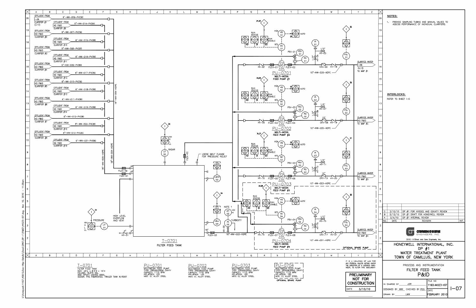
A low-low (LL) liquid level in the Filter Feed Tank.. as indicated by UT-0701-00, LlT-0701-01, or LSLL-0701-00, v.~ II shut down
Multimedia Feed Pumps PU-0701, PU-0702., PU-0703, and PU-0704.
Coordinate signal(s) bad< from SCA, induding "fault" orsimil ar atthe Polymer Syst£ m, to shut off the POI''t'trIlH MakedownPump (PU-1001).
At low-l ow (LL) Ii quid level in Flash Mix Tank, shu"! down Mixers. Alsoshut influent valve FV-02 on 1-01
A low flow rate.. as indicated by FSljFAL-01, v.~11 shut down Multime dia Fe ed Pump #1 (PU-0701)
A low flow rate, as indicated by FSljFAL-02., v.111 shut down Multimedia Feed Pump #2. (PU-0702.)
A low flow rate, as indicated b'r' FSljFAL-04, will shut down Multimedia Feed Pump #4 (PU-0704)
Deleted
Shutinfluentfeedvalve FV-02.(on 1-01) ata high-high liquid level in Effluent Monitoring Tank T-l001, as indicated by L1C-l001
00 or LSHI+1001-00.
Shut GAC-090lA/B feed valve FCV-DO (on I-CS) at high-high flow (as indicated bV FE/FIQ1/FIC-00 on 1-(8) to preve ntinadeQuat£
rontacttime in GACs.
A high-high (HH) differential pressure across Multimedia Filter#l (MMF-08Dl),. as indicated by PDIT-CB01-D0. v.111 start the idled
spare Multimedia Filter and corresponding Multi media Feed Pump, and shutthe valve(s) feeding Multimedia Filter #1.
A low flow rate, as indicated by FSljFAL-03, will shut down Multimedia Feed Pump #3 (PU-0703)
IT IS A VIOLATION OF LAW FORANY PERSON. UNLESS ACTING UNDERTHE DIRECTION OF A LICENSED ENGINEER, TO ALTER THIS DOCUMENT.
A high-high (HH) differential pressure across f\.'1ultimedia Filter#2. (MMF-08D2.), as indicated by PDIT-0802.-DQ. v.111 startthe idled
spare Multimedia Filter and corresponding Multi medi aFeed Pump.. and shutthe valve(s) feeding Multimedia Filter #2..
A high-high (HH) differential pr'£ssure across Multimedia Filter#3 (MMF-08D3), as indicated by PDIT-08Q3-DO. wi II start the idled
spare Multimedia Filter and corresponding Multi medi aFeed Pump. and shutthe valve(s) feeding Multimedia Filter #3.
A high-high (HH) differential pressure across Multimedia Filter#4 (MMF-0804), as indicated by PDIT-08C4-DQ. wi II start the idledspare Multimedia Filter and corresponding Multi media Feed Pump.. and shutthe valve(s) feeding Multimedia Filter #4.
Ata no (Le ... low-low (LLj) flow to pH AdjustmentTrain 2 (as indicated b"'t' FE/FIC-Dl on 1-01), shut offsulfuric add pumps CF-1203and CF-12M and caustic feed pumps CF-1303 and CF-BM.
At a no (Le., low-low (LLj) flow to pH AdjustmentTrain 1 (as indicated by FE/FIC-DO on 1-01).. shut off sulfuric add pumps CF-1201and CF-1202 and caustic feed pumps CF-1301 and CF-B02..
NA (Pertains to Inclined
30 PI ate CI jrifie r #15)
NA (Pertains to Inclined
31 PI ate CI arifier #16)32
33 1-01,1-06
34 1-0735 I-D7
36 1-0737 1-07
38 1-07
39 1-08
NA (Pertains to
4D r...1ultimedia Filt£r#2.)
NA (Pertains to
41 Multimedia Filt£r#3)
NA (Pertains to42 Multimedia Filt£r#4)
43 1-01,1-08
44 1-08,1-09
45 1-10,1-15
46 1-01.. 1-10
47 1-10
49- 1-10
49 1-10
50 1-11
51 1-11
I-~. 1-10.. 1-11, 1-103, 1-
52 10753
54 1-08
55 1-01,1-105657 1-01,1-03
58 1-01, 1-14, 1-15
59 1-01.. 1-14.1-15fA) 1-12.. 1-15
61 I-B,I-1462. I-B,I-16
At a Jaw liquid leve I in lnclined PIa:e Clarifier #2, as in dicered IJlI LSL/IAL-C602-00, Clarifier SludgeV~ e #2 (FV) will cJose.
Close FV-·02 on 1-01. Shut off Floe Mixer.
At a Jaw liqUid level in Inclined Pla:e Clarifier #1, as indicered by LSL/IAL-C601-00, Clarifier SludgeV~e#1 (FV) will close.
Close FV-02on 1-01. Shut off Floe Mixer.
Deleted
At a low liquid level in lnclined Pla:e Clarifier #8, as indica:ed by LSL/IAL-C6D8-00, Clarifier Sludge Va've #8 (FV) will close.
Close FV-02 on 1-01. Shut off Floe Mixer.
At a low liqUid level in Inclined Pla:e Clarifier #6, as indica:ed by LSL/IAL-C606-00, Clarifier SludgeV~e #6 (FV) will close.Close FV-02 on 1-01. Shut off Floe Mixer.
At a low liquid leve j in lnclined PIa:e Clarifier #4, as indicered by LSL/IAL-05C4-oo, Clarifier Sludge Va'v e #4 (FV) w ill close.
Close FV-02 on 1-01. Sllut off Floe Mbeer.
HoneywellSCA WTP
Draft Interlock List7-Apr-1O
At a high-high (HH) or low-low (LL) pH in pHAdjust lank #8 (! -0108), as indicered by AE/AIJ:/AIC-Ol03-00, pHAdjust Tank #5
influent valve FCV-01 will close
At a Jaw liquid le....el in lnclined PJa:e Clarifier #5, as indicered by LSL/IAL-05G5-00, Clarifier Sludge Varve #5 (FV) w ill close.Close FV-02on 1-01. Shut off Floe Mixer.
Description
At a Iligh-higll (HH) or low-low (LL) pH in pH Adjust Tank #4 (T-0104), as indicered by AE/All/AIC-D104-00, pHAdjust Tank #1influentvawe FCV-OOwill close
At a lOl/,' liquid level in Inclined Pla:e Clarifier #9, as indica:ed by LSL/IAL-C6C9-00, Clarifier Sludge Valve #9 (FV) will close.
Close FV-02 on 1-01. Shut off Floe Mbeer.
At a low liqUid level in lnclined Pla:e Clarifier #7, as indica:ed by LSL/IAL-C607-00, Clarifier Sludge Valve #7 (FV) will close.Close FV-02 on 1-01. Sllut off Floe Mixer.
Ata low (L) liqUid level in pH Adjust Tank #8 (1-0103), as indica:ed by LSL.!IAL-Ol08-00, Mixers MIX-OlO8A, 01038, 010Be, and
01080 will aJtomatically shut down.
At a low (L) liquid level in pH Adjust Tank #1 (T-0101), as indicered by LSL/IAL-Ol0l-00, f!.'1ixers r..'1IX-Ol0lA, 01018, 0101C, and
0101Dwill automerically 91utdown. Stop tile addition ofsodiumllydr(Jl(ide orsulfurica::id by sIlutting down CF-l2Dl and CF1301, respectiveiy. Sllut FCV-OO on 1-01.
At a low liqUid level in Inclined Plere Clarifier #3, as indicered by LSL/IAL-C603-00, Clarifier Sludge Valve #3 (FV) will close.
Close FV-02 on 1-01. SI1Ut off Floe Mbeer.
At a low alum flow from CF-1401, as indicered by FSL/FAL-OO, VI/TP influent valve FV-02 will close
At a low (L) liquid level in pH Adjust Tank #5 (T-0105), as indicered by LSL/IAL-01D5-00, r...1ixers MIX-Ol0SA, 01058, 0105C, and01C5Dwill cutomerically shutdown. Stop tile addition of sodium Iwdr(Jl(ide orsulfurica::id by shutting down CF-12D3 and CF
1303, respectively.
At a low (L) liquid level in pH Adjust lank #3 (T-0103), as indica:ed by LSL/IAL-Ol03-00, Mixers MIX-OlO3A, 01038, 0103C, and
0103DwilJ automerically sIlut down. Stop tile addition of sodium llydr(Jl(ide or sulfuric a::id by 91utting down CF-12D2 and CF1302, respectively.
At a low (L) liqUid level in pH Adjust Tank #2 (T-0102), as indicered by LSL/IAL-D102-00, rV1ixers MIX-OlO2A, 01028, 0102C, and
01020 will automerically sllut down. Alsosllut FCV-OO on 1-01 to prevent additional leakage.
At a low (L) liquid level in pH Adjust Tank #4 (T-0104), as indicered by LSL/IAL-Ol04-00, Mixers MIX-0104A, 01048, 0104C, and
01040 will aJtomatjcally sllut down.At a low (L) liqUid level in pH Adjust Tank #6 (T-01C6), as indica:ed by LSL/IAL-.Q106-00, Mixers r...UX-Ol0eA, 01068, 010se, and
01060 will aJtomatically sllut down.
At a low (L) liquid level in pH Adjust Tank #7 (T-0107), as indicered by LSL/IAL-Ol07-00, Mixers MIX-0107A, 01078, 0107C, and01070 w ill automa:icaHy 91 ut down. Stop tile additi on of sodium llydr(Jl( ide or sui fu ric a::id by 91 utting down CF-1204 and CF
1304, respectively.
At a Iligll-Il igll (HH) influent tu rbidity, as indicated by A E/Ail-GO, WiP influent valv e F\l-02 w ill automerically clog:. Coord inere
witlltlleSCAproject, to determine if avalve position signal can beug:dto shut down tile SCA discllargepumps.
At a Iligll (H) liquid level in pHAdjust Tank #1 (T-Ol0l), as indjcered by LSH/IAH-Dl0l-0Q, tank influent valve FCV-oOwi H
automericaBy dose. Stop tile addition of sodi um IlYdroxideor sutfurjc add by sllutting down CF-1201 andCF-1301, respectively.
Coordina:e with tile SCA proj ect.. to determine if avalve position signal can besent toSCA to reduce pumping (i.e., VI/TP could
cantin ue to receiv eone-Ilalf flow to pH Adj ustTank#5)
At a Iligll (H) liqUid level in pHAdjust Tank #5 (T-0105), as indicered by LSH/IAH-Dl05-GO, tank influent valve FCV-ol willautometicall't' close. Stop tile add ition of sodiurn Ilyd roxid ear su lfurlc add IJlI sllutting down CF-1203 an dCF-1303, respectiv ely .
Coordinerewith tile SCA proj ect, to determine if avalve position signal can besent toSCA to reduce pumping (i.e .., VI/TP couldcontinuetoreceiveone-Ilalfflow to pH AdjustTank#l)
NA (P ertains to pH
Adj ustTank #4)
NA (P ertains to pH
Adj ustTank #3), 1-14, 1
15
NA (PertainstopHAdjustTank#7), 1-14,1
15
1-01,1-16
NA (P ertainsto pH
Adj ustTank #5),1-01, J14,1-15
1-01,1-06
l-Dl, and NA (Pertainsto pH Adjust Tank #4)
NA (PertainstopH
Adj ustTank #6)
1-01, 1-14, 1-15
1-01, and NA (Pertains
to pH Adj ust Tank #8)
1-01,1-14, 1-15
1-01,1-02
NA (P ertains to pH
Adj ustTank #8)
1-01
NA (P ertainsto pHAdj ustTank #5).1-14, l
is
P&ID(s)
NA (Pertains to Inclined
Pla:e Clarifier #2)
NA (Pertainsto Inclined
Plere Clarifier #4)
NA (Pertains to Inclined
Plere Clarifier #3)
NA (Pertainsto Inclined
Pla:e Clarifier #8)
NA (Pertainsto InclinedPJa:e Clarifier #7)
NA (Pertainsto InclinedPla:e Clarifier #5)
NA (Pertains to InclinedPla:e Clarifier #6)
NA (Pertainsto Inclined
Pla:e Clarifier #9)
NA (Pertains to Inclined At a low liquid level in Inclined PlateClarifier#10, as indicered by LSL/IAL-0610-00, Clarifier Sludge Valve #10(FV) will close.
PI a:e Clarifier #10) Close FV-02 on 1-01. Sllut off Floe Mixer.
interlock No.
10
11
12
1314
15
16
17
18
19
2D
(J> 21
~0I
I 22f")N111'<t'<t
23f(1)
~(f).,,/ 24I
0...0.,,/<..') 253:0
~0 260
f0(1)
270IQ..
~
8 28(f)
r<)
U;111 29'<t.,,/n(0
-Q)
f0
:r:-;;

NOTES:
©
INTERLOCKS:

NOTES:
©
INTERLOCKS:

NOTES:
©
INTERLOCKS:

NOTES:
©
INTERLOCKS:

NOTES:
©
INTERLOCKS:

NOTES:
©
INTERLOCKS:
NOTES:
©
INTERLOCKS:

NOTES:
©
INTERLOCKS:

INTERLOCKS:
NOTES:
©

NOTES:
©
INTERLOCKS:

NOTES:
©
INTERLOCKS:

INTERLOCKS:
NOTES:
©

INTERLOCKS:
NOTES:
©

INTERLOCKS:
NOTES:
©

INTERLOCKS:
NOTES:
©

INTERLOCKS:
NOTES:
©

NOTES:
©
INTERLOCKS:

NOTES:
©
INTERLOCKS:

NOTES:
INTERLOCKS:
©


INTERLOCKS:
NOTES:
©

NOTES:
©
INTERLOCKS:

NOTES:
©
INTERLOCKS:

INTERLOCKS:
NOTES:
©

INTERLOCKS:
NOTES:
©

TECHNICAL SPECIFICATIONS

01160-1 1163/45613
03/10 Spill and Discharge Control
SECTION 01160 SPILL AND DISCHARGE CONTROL PART 1 GENERAL 1.1 WORK INCLUDED
A. Preparation, submission, and implementation of an acceptable Spill and Discharge Control Plan by the Contractor as specified herein and in accordance with all provisions of the Contract Documents.
1.2 RELATED WORK SPECIFIED ELSEWHERE
A. Honeywell Syracuse Portfolio Health and Safety Programs (HSP2) 1.3 APPLICABLE CODES, STANDARDS, AND SPECIFICATIONS
A. Not Used. 1.4 SUBMITTALS
A. The following items shall be submitted:
1. Spill and Discharge Control Plan 2. Spill Incident Reports
PART 2 PRODUCTS 2.1 GENERAL
A. Spill and Discharge Control (SDC) Plan
1. The Contractor shall develop, implement, maintain, supervise, and be responsible for a Spill and Discharge Control Plan. This SDC Plan shall provide contingency measures for potential spills of oil and hazardous materials and construction-related materials including, but not limited to, fuels, hydraulic fluids, lubricants, and construction water.
2. Procedures outlined in the SDC Plan shall follow applicable local, State,
and Federal laws and regulations. The plan shall, at a minimum, contain the following:
a. Procedures for Containing Dry and Liquid Spills. b. Absorbent Material available on-site. c. Procedures for collection, storage, and handling/disposal of spilled
materials. d. Decontamination Procedures. Decontamination procedures may be
required after cleanup to eliminate traces of the substance spilled or reduce it to an acceptable level. Acceptable levels shall be in accordance with all applicable local, State, and Federal laws and
01160-2 1163/45613
03/10 Spill and Discharge Control
regulations and shall be approved by the New York State Department of Environmental Conservation (NYSDEC). Complete cleanup may require removal of contaminated soils. All contaminated materials that cannot be decontaminated must be properly containerized, labeled, and properly disposed of within 90 days. Any and all testing and disposal costs related to the cleanup of a spill caused by the Contractor's activities shall be borne by the Contractor.
e. Spill Incident Report Format. A written report detailing the spill or discharge shall include, at a minimum, the cause and resolution of the incident, the substance and quantity spilled, outside agencies involved, date and time the incident occurred and actions taken to prevent incident reoccurrence. The report shall be submitted to the Owner’s Representative, the Owner, and NYSDEC, within 24 hours of the incident, and earlier if necessary to comply with local, state, or federal regulations. The Contractor shall document the location of all spills on the Site Drawings and submit the Drawings to the Owner’s Representative at project completion.
B. Spill and Discharge Control
1. The Contractor shall provide methods, means, equipment, facilities, and
personnel required to prevent contamination of soil, water, air, equipment, or materials by the discharge of bulk wastes from spills due to Contractor's operations.
2. The Contractor shall provide methods, means, equipment, facilities and
personnel to perform emergency measures required to contain any spillage and to remove spilled materials and soils or liquids that become contaminated due to spillage. All collected spill material shall be properly disposed of at the Contractor's expense.
C. Decontamination
1. The Contractor shall provide equipment and personnel to perform
decontamination measures that may be required to remove spillage from previously uncontaminated structures, equipment, or material. Decontamination residues shall be properly disposed of at the Contractor's expense. Hazardous waste shall be handled in accordance with local, state and Federal regulations.
PART 3 EXECUTION 3.1 GENERAL
A. Contractor shall be responsible for all liabilities related to spills, discharges, leaks, or emissions from equipment, tankage, vessels, drums, or any other devices owned, operated, or controlled by the Contractor, his subcontractors, vendors, personnel, agents, or assigns.
B. In the case of a spill or discharge, the Contractor shall follow procedures outlined in
the SDC Plan.

01160-3 1163/45613
03/10 Spill and Discharge Control
3.2 NOTIFICATION
A. The Contractor shall notify the Owner and Owner’s Representative at the time of occurrence and follow-up in writing within 24 hours.
B. The Contractor shall report a spill or discharge to regulatory agencies, as necessary
to comply with local, state, and federal regulations. * * * * *

02111-1 1163/45613
03/10 Clearing and Grubbing
SECTION 02111 CLEARING AND GRUBBING PART 1 GENERAL 1.1 SUMMARY
A. This Section includes clearing and grubbing by removal or destruction of trees, underbrush, logs, stumps, decayed or growing organic matter above the surface of the ground, and snow and ice which interfere with construction or landscaping, specified or directed within or adjacent to the lines of work.
1.2 RELATED WORK SPECIFIED ELSEWHERE
A. Earthwork, Section 02220 B. Restoration of Surfaces, Section 02503
PART 2 PRODUCTS 2.1 Not Used. PART 3 EXECUTION 3.1 GENERAL
A. Only those portions of the site necessary and essential to be cleared for work shall be cleared.
B. Removal of brush, trees, stumps, and spoil
1. Contractor shall chip brush, tree trunks and tree limbs.
2. Contractor shall likewise chip tree stumps, provided however, that if the tree
was located in a potentially contaminated area, all soil adhering to the stump must first be removed prior to chipping. Soil adhering to the stump shall be handled in a manner accepted by the Owner’s Representative.
3. All chipped brush, trees, stumps, and spoil material shall be removed from
the area and disposed of by the Contractor in a manner accepted by the Owner and Owner’s Representative.
* * * * *

02220-1 1163/45613
03/10 Earthwork
SECTION 02220 EARTHWORK PART 1 GENERAL 1.1 SUMMARY
A. This Section includes excavation and backfilling including the loosening, removing, refilling, transporting, storage and disposal of all materials classified as "earth" necessary to be removed for the construction and completion of all work under the Contract, and as shown on the Contract Drawings, specified or directed.
1.2 REFERENCES
A. Materials and installation shall be in accordance with the latest revisions of the following codes, standards, and specifications, except where more stringent requirements have been specified herein:
1. American Society for Testing and Materials (ASTM)
a. A328 Specification for Steel Sheet Piling b. D698 Test Method for Laboratory Compaction Characteristics of
Soil Using Standard Effort (12,400 ft-lbf/ft3) (600 kN-m/m3
c. D1556 Test Method for Density and Unit Weight of Soil in Place by the Sand-Cone Method
)
d. D1760 Specification for Pressure Treatment of Timber Products e. D2922 Test Methods for Density of Soil and Soil Aggregate in
Place by Nuclear Methods (Shallow Depth)
1.3 RELATED WORK SPECIFIED ELSEWHERE
A. Material Handling and Disposal, Section 01170
1.4 DEFINITIONS
A. Excavation (or Trenching)
1. Grubbing, stripping, removing, storing and rehandling of all materials of every name and nature necessary to be removed for all purposes incidental to the construction and completion of all the work under construction.
2. All sheeting, sheetpiling, bracing and shoring, and the placing, driving,
cutting off and removing of the same. 3. All diking, ditching, fluming, cofferdamming, pumping, bailing, draining,
well pointing, or otherwise disposing of water.
4. The removing and disposing of all surplus materials from the excavations in the manner specified.
5. The maintenance, accommodation and protection of travel.

02220-2 1163/45613
03/10 Earthwork
6. The supporting and protecting of all tracks, rails, buildings, curbs,
sidewalks, pavements, overhead wires, poles, trees, vines, shrubbery, pipes, sewers, conduits or other structures or property in the vicinity of the work, whether over- or underground or which appear within or adjacent to the excavations, and the restoration of the same in case of settlement or other injury.
7. All temporary bridging and fencing and the removing of same.
B. Earth
1. All materials such as sand, gravel, clay, loam, ashes, cinders, pavements,
muck, roots or pieces of timber, soft or disintegrated rock, not requiring blasting, barring, or wedging from their original beds, and specifically excluding all ledge or bedrock and individual boulders or masonry larger than one-half cubic yard in volume.
C. Backfill
1. The refilling of excavation and trenches to the line of filling indicated on the
Contract Drawings or as directed using materials suitable for refilling of excavations and trenches; and the compacting of all materials used in filling or refilling by rolling, ramming, watering, puddling, etc., as may be required.
D. Spoil
1. Surplus excavated materials not required or not suitable for backfills or
embankments.
E. Embankments
1. Fills constructed above the original surface of the ground or such other elevation as specified or directed.
F. Limiting Subgrade
1. 6-inches below the underside of the pipe barrel for pipelines 2. 6-inches below the underside of footing lines for structures
G. Excavation Below Subgrade
1. Excavation below the limiting subgrades of structures or pipelines.
2. Where materials encountered at the limiting subgrades are not suitable for
proper support of structures or pipelines, the Contractor shall excavate to such new lines and grades as required.
02220-3 1163/45613
03/10 Earthwork
PART 2 PRODUCTS 2.1 MATERIALS AND CONSTRUCTION
A. Wood Sheeting and Bracing
1. Shall be sound and straight; free from cracks, shakes and large or loose knots; and shall have dressed edges where directed.
2. Shall conform to National Design Specifications for Stress Grade Lumber
having a minimum fiber stress of 1200 pounds per square inch.
3. Sheeting and bracing to be left-in-place shall be pressure treated in accordance with ASTM D1760 for the type of lumber used and with a preservative approved by the Owner’s Representative.
B. Steel Sheeting and Bracing
1. Shall be sound
2. Shall conform to ASTM A328 with a minimum thickness of 3/8 inch.
PART 3 EXECUTION 3.1 UNAUTHORIZED EXCAVATION
A. Whenever excavations are carried beyond or below the lines and grades shown on the Contract Drawings, or as given or directed by the Owner’s Representative, all such excavated space shall be refilled with special granular materials, concrete or other materials as the Owner’s Representative may direct. All refilling of unauthorized excavations shall be at the Contractor's expense.
B. All material which slides, falls or caves into the established limits of excavations
due to any cause whatsoever, shall be removed and disposed of at the Contractor's expense and no extra compensation will be paid the Contractor for any materials ordered for refilling the void areas left by the slide, fall or cave-in.
3.2 REMOVAL OF WATER
A. General
1. The Contractor shall at all times provide and maintain proper and satisfactory means and devices for the removal of all water entering the excavations, and shall remove all such water as fast as it may collect, in such manner as shall not interfere with the prosecution of the work or the proper placing of pipes, structures, or other work.
2. Unless otherwise specified, all excavations which extend down to or below
the static groundwater elevations shall be dewatered by lowering and maintaining the groundwater beneath such excavations at all times when work thereon is in progress, during subgrade preparation and the placing of the structure or pipe thereon.

02220-4 1163/45613
03/10 Earthwork
3. Water shall not be allowed to rise over or come in contact with any
masonry, concrete or mortar, until at least 24 hours after placement, and no stream of water shall be allowed to flow over such work until such time as the Owner’s Representative may permit.
4. Where the presence of fine grained subsurface materials and a high
groundwater table may cause the upward flow of water into the excavation with a resulting quick or unstable condition, the Contractor shall install and operate a well point system to prevent the upward flow of water during construction.
5. Water pumped or drained from excavations, or any sewers, drains or water
courses encountered in the work, shall be managed per Section 02141 Construction Water Management and without injury to adjacent property, the work under construction, or to pavements, roads, drives, and water courses. No water shall be discharged to sanitary sewers.
6. Any damage caused by or resulting from dewatering operations shall be the
sole responsibility of the Contractor.
B. Work Included
1. The construction and removal of sheeting and bracing, and the furnishing of materials and labor necessary therefor.
2. The excavation and maintenance of ditches.
3. The furnishing and operation of pumps, well points, and appliances needed
to maintain thorough drainage of the work in a satisfactory manner. 3.3 STORAGE OF MATERIALS
A. Sod
1. Any sod cut during excavation shall be removed and stored during construction so as to preserve the grass growth. Sod damaged while in storage shall be replaced in like kind at the sole expense of the Contractor.
B. Topsoil
1. Topsoil suitable for final grading shall be removed and stored separately
from other excavated material.
C. Excavated Materials
1. All excavated materials shall be stored in locations so as not to endanger the work, and so that easy access may be had at all times to all parts of the excavation. Stored materials shall be kept neatly piled and trimmed, so as to cause as little inconvenience as possible to public travel or to adjoining property holders. Erosion & Sediment control practices shall be installed, inspected, and maintained around stockpiled material.

02220-5 1163/45613
03/10 Earthwork
2. Special precautions must be taken to permit access at all times to fire
hydrants, fire alarm boxes, police and fire department driveways, and other points where access may involve the safety and welfare of the general public.
3.4 DISPOSAL OF MATERIALS
A. Spoil Material
1. All spoil materials shall be disposed of on site in a location designated by the Owner’s Representative and as required by the local, state or federal regulations pertaining to the area.
2. The surface of all spoil areas shall be graded and dressed and no unsightly
mounds or heaps shall be left on completion of the work. 3.5 SHEETING AND BRACING
A. Installation
1. The Contractor shall furnish, place and maintain such sheeting, bracing and shoring as may be required to support the sides and ends of excavations in such manner as to prevent any movement which could, in any way, injure the pipe, structures, or other work; diminish the width necessary for construction; otherwise damage or delay the work of the Contract; endanger existing structures, pipes or pavements; or cause the excavation limits to exceed the right-of-way limits.
2. In no case will bracing be permitted against pipes or structures in trenches
or other excavations.
3. Sheeting shall be driven as the excavation progresses, and in such manner as to maintain pressure against the original ground at all times. The sheeting shall be driven vertically with the edges tight together, and all bracing shall be of such design and strength as to maintain the sheeting in its proper position. Seepage which carries fines through the sheeting shall be plugged to retain the fines.
4. Where breast boards are used between soldier pile, the boards shall be back
packed with soil to maintain support.
5. The Contractor shall be solely responsible for the adequacy of all sheeting and bracing.
B. Removal
1. In general, all sheeting and bracing, whether of steel, wood or other
material, used to support the sides of trenches or other open excavations, shall be withdrawn as the trenches or other open excavations are being refilled. That portion of the sheeting extending below the top of a pipe or structural foundation shall not be withdrawn, unless otherwise directed,

02220-6 1163/45613
03/10 Earthwork
before more than 6 inches of earth is placed above the top of the pipe or structural foundation and before any bracing is removed. The voids left by the sheeting shall be carefully refilled with selected material and rammed tight with tools especially adapted for the purpose or otherwise as may be approved.
2. The Contractor shall not remove sheeting and bracing until the work has
attained the necessary strength to permit placing of backfill.
C. Left in Place
1. If, to serve any purpose of his own, the Contractor files a written request for permission to leave sheeting or bracing in the trench or excavation, the Owner’s Representative may grant such permission, in writing, on condition that the cost of such sheeting and bracing be assumed and paid by the Contractor.
2. The Contractor shall leave in place all sheeting, shoring and bracing which
are shown on the Contract Drawings or specified to be left in place or which the Owner’s Representative may order, in writing, to be left in place. All shoring, sheeting and bracing shown or ordered to be left in place will be paid for under the appropriate item of the Contract. No payment allowance will be made for wasted ends or for portions above the proposed cutoff level which are driven down instead of cut-off.
3. In case sheeting is left in place, it shall be cut off or driven down as directed
so that no portion of the same shall remain within 24 inches of the street subgrade or finished ground surface.
3.6 BACKFILLING
A. General
1. All excavations shall be backfilled to the original surface of the ground or to such other grades as may be shown, specified or directed.
2. Backfilling shall be done with suitable excavated materials which can be
satisfactorily compacted during refilling of the excavation. In the event the excavated materials are not suitable, Special Backfill as specified or ordered by the Owner’s Representative shall be used for backfilling.
3. Any settlement occurring in the backfilled excavations shall be refilled and
compacted. B. Unsuitable Materials
1. Stones, pieces of rock or pieces of pavement greater than 1 cubic foot in
volume or greater than 1.5 feet in any single dimension shall not be used in any portion of the backfill.

02220-7 1163/45613
03/10 Earthwork
2. All stones, pieces of rock or pavement shall be distributed through the backfill and alternated with earth backfill in such a manner that all interstices between them shall be filled with earth.
3. Frozen earth shall not be used for backfilling.
C. Compaction and Density Control
1. The compaction shall be as specified for the type of earthwork, i.e.,
structural, trenching or embankment.
a. The compaction specified shall be the percent of maximum dry density.
b. The compaction equipment shall be suitable for the material encountered.
2. Where required, to assure adequate compaction, in-place density test shall at
the expense of the Contractor be made by an approved testing laboratory.
a. The moisture-density relationship of the backfill material shall be determined by ASTM D698, Method D. 1) Compaction curves for the full range of materials used shall
be developed. b. In-place density shall be determined by the methods of ASTM
D1556 or ASTM D2922 and shall be expressed as a percentage of maximum dry density.
3. Where required, to obtain the optimum moisture content, the Contractor
shall add, at his expense, sufficient water during compaction to assure the specified maximum density of the backfill. If, due to rain or other causes, the material exceeds the optimum moisture content, it shall be allowed to dry, assisted if necessary, before resuming compaction or filling efforts.
4. The Contractor shall be responsible for all damage or injury done to pipes,
structures, property or persons due to improper placing or compacting of backfill.
3.7 OTHER REQUIREMENTS
A. Drainage
1. All material deposited in roadway ditches or other water courses shall be removed immediately after backfilling is completed and the section, grades and contours of such ditches or water courses restored to their original condition, in order that surface drainage will be obstructed no longer than necessary.
B. Unfinished Work
1. When, for any reason, the work is to be left unfinished, all trenches and
excavations shall be filled and all roadways, sidewalks and watercourses left
02220-8 1163/45613
03/10 Earthwork
unobstructed with their surfaces in a safe and satisfactory condition. The surface of all roadways and sidewalks shall have a temporary pavement.
C. Hauling Material on Streets
1. When it is necessary to haul material over the streets or pavements, the
Contractor shall provide suitable tight vehicles so as to prevent deposits on the streets or pavements. In all cases where any materials are dropped from the vehicles, the Contractor shall clean up the same as often as required to keep the crosswalks, streets and pavements clean and free from dirt, mud, stone and other hauled material.
D. Dust Control
1. It shall be the sole responsibility of the Contractor to control the dust
created by any and all of his operations to such a degree that it will not endanger the safety and welfare of the general public.
2. Calcium chloride, chemicals, and petroleum products shall not to be used
for dust control.
E. Test Pits
1. For the purpose of obtaining detail locations of underground obstructions, the Contractor shall make excavations in advance of the work or as ordered by Owner’s Representative. Test pits shall include sheeting, bracing, pumping, excavation and backfilling.
* * * * *

02226-1 1163/45613
03/10 Trenching, Backfilling and Compacting
SECTION 02226 TRENCHING, BACKFILLING AND COMPACTING PART 1 GENERAL 1.1 SUMMARY
A. This Section includes excavation and backfill as required for pipe installation or other construction in the trench, and removal and disposal of water, in accordance with the applicable provisions of the Section entitled "Earthwork" unless modified herein.
PART 2 PRODUCTS
NOT USED PART 3 EXECUTION 3.1 EXCAVATION
A. The trench excavation shall be located as shown on the Contract Drawings or as specified. Under ordinary conditions, excavation shall be by open cut from the ground surface. Where the depth of trench and soil conditions permit, tunneling may be required beneath cross walks, curbs, gutters, pavements, trees, driveways, railroad tracks and other surface structures. No additional compensation will be allowed for such tunneling over the price bid for open cut excavation of equivalent depths below the ground surface unless such tunnel excavation is specifically provided for in the Contract Documents.
B. Trenches shall be excavated to maintain the depths as shown on the Contract
Drawings or as specified for the type of pipe to be installed.
C. The alignment and depth shall be determined and maintained by the use of a string line installed on batter boards above the trench, a double string line installed along side of the trench or a laser beam system.
D. The minimum width of trench excavation shall be 6 inches on each side of the pipe
hub for 21-inch diameter pipe and smaller and 12 inches on each side of the pipe hub for 24-inch diameter pipe and larger.
E. Trenches shall not be opened for more than 300 feet in advance of pipe installation
nor left unfilled for more than 100 feet in the rear of the installed pipe when work is in progress without the consent of the Engineer. Open trenches shall be protected and barricaded as required.
F. Bridging across open trenches shall be constructed and maintained where required.

02226-2 1163/45613
03/10 Trenching, Backfilling and Compacting
3.2 SUBGRADE PREPARATION FOR PIPE
A. Where pipe is to be laid on undisturbed bottom of excavated trench, mechanical excavation shall not extend lower than the finished subgrade elevation at any point.
B. Where pipe is to be laid on special granular material the excavation below subgrade
shall be to the depth specified or directed. The excavation below subgrade shall be refilled with special granular material as specified or directed, shall be deposited in layers not to exceed 6 inches and shall be thoroughly compacted prior to the preparation of pipe subgrade.
C. The subgrade shall be prepared by shaping with hand tools to the contour of the pipe
barrel to allow for uniform and continuous bearing and support on solid undisturbed ground or embedment for the entire length of the pipe.
D. Pipe subgrade preparation shall be performed immediately prior to installing the
pipe in the trench. Where bell holes are required they shall be made after the subgrade preparation is complete and shall be only of sufficient length to prevent any part of the bell from becoming in contact with the trench bottom and allowing space for joint assembly.
3.3 STORAGE OF MATERIALS
A. Traffic shall be maintained at all times in accordance with the applicable Highway Permits. Where no Highway Permit is required at least one-half of the street must be kept open for traffic.
B. Where conditions do not permit storage of materials adjacent to the trench, the
material excavated from a length as may be required, shall be removed by the Contractor, at his cost and expense, as soon as excavated. The material subsequently excavated shall be used to refill the trench where the pipe had been built, provided it be of suitable character. The excess material shall be removed to locations selected and obtained by the Contractor.
1. The Contractor shall, at his cost and expense, bring back adequate amounts
of satisfactory excavated materials as may be required to properly refill the trenches.
C. If directed by the Engineer, the Contractor shall refill trenches with select fill or
other suitable materials and excess excavated materials shall be disposed of as spoil. 3.4 REMOVAL OF WATER AND DRAINAGE
A. The Contractor shall at all times provide and maintain proper and satisfactory means and devices for the removal of all water entering the trench, and shall remove all such water as fast as it may collect, in such manner as shall not interfere with the prosecution of the work.
B. The removal of water shall be in accordance with the Section entitled "Earthwork".

02226-3 1163/45613
03/10 Trenching, Backfilling and Compacting
3.5 PIPE EMBEDMENT
A. All pipe shall be protected from lateral displacement and possible damage resulting from superimposed backfill loads, impact or unbalanced loading during backfilling operations by being adequately embedded in suitable pipe embedment material. To ensure adequate lateral and vertical stability of the installed pipe during pipe jointing and embedment operations, a sufficient amount of the pipe embedment material to hold the pipe in rigid alignment shall be uniformly deposited and thoroughly compacted on each side, and back of the bell, of each pipe as laid.
B. Concrete cradle and encasement of the class specified shall be installed where and
as shown on the Contract Drawings or ordered by the Engineer. Before any concrete is placed, the pipe shall be securely blocked and braced to prevent movement or flotation. The concrete cradle or encasement shall extend the full width of the trench as excavated unless otherwise authorized by the Engineer. Where concrete is to be placed in a sheeted trench it shall be poured directly against sheeting to be left in place or against a bond-breaker if the sheeting is to be removed.
C. Embedment materials placed above the centerline of the pipe or above the concrete
cradle to a depth of 12 inches above the top of the pipe barrel shall be deposited in such manner as to not damage the pipe. Compaction shall be as required for the type of embedment being installed.
3.6 BACKFILL ABOVE EMBEDMENT
A. The remaining portion of the pipe trench above the embedment shall be refilled with suitable materials compacted as specified.
1. Where trenches are within the Site area or road or within a driveway, shall
be under a structure, the trench shall be refilled in horizontal layers not more than 8 inches in thickness, and compacted to obtain 95% maximum density, and determined as set forth in the Section entitled "Earthwork".
2. Where trenches are in open fields or unimproved areas, the trench shall be
refilled in horizontal layers not more than 8 inches in thickness, and compacted to obtain 90% maximum density.
3. Hand tamping shall be required around buried utility lines or other
subsurface features that could be damaged by mechanical compaction equipment.
B. Backfilling of trenches beneath, across or adjacent to drainage ditches and water
courses shall be done in such a manner that water will not accumulate in unfilled or partially filled trenches and the backfill shall be protected from surface erosion by adequate means.
1. Where trenches cross waterways, the backfill surface exposed on the bottom
and slopes thereof shall be protected by means of stone or concrete rip-rap or pavement.
C. All settlement of the backfill shall be refilled and compacted as it occurs.
02226-4 1163/45613
03/10 Trenching, Backfilling and Compacting
D. Temporary pavement shall be placed as specified in the Section entitled
"Restoration of Surfaces". * * * * *

02230-1 1163/45613
03/10 Select Fill
SECTION 02230
SELECT FILL PART 1 GENERAL 1.1 SUMMARY
A. This Section includes select fill materials used in either embedment or special backfill, as specified or as directed by the Owner.
1.2 REFERENCES
A. Materials and installation shall be in accordance with the latest revisions of the following codes, standards, and specifications, except where more stringent requirements have been specified herein:
1. American Society for Testing and Materials (ASTM)
a. D422 - Method for Particle-Size Analysis of Soil
1.3 SUBMITTALS
A. The following items shall be submitted:
1. The name and location of the source of the material. 2. Samples and test reports of the material.
1.4 DEFINITIONS
A. Embedment or Lining
1. Any type granular material specified or directed placed below an imaginary line drawn one foot above the inside diameter of the pipe and within the trench limits.
B. Special Backfill
1. Pipelines
a. Any select fill material specified or directed placed above an imaginary
line drawn one foot above the inside diameter of the pipe and within the trench limits.
2. Structures
a. Any select fill material specified or directed placed within the excavation
limits, either in, under or adjacent to the structure.

02230-2 1163/45613
03/10 Select Fill
C. Special Granular Material
1. Special granular material shall mean any of the granular materials listed below or other materials ordered by the Owner.
PART 2 PRODUCTS 2.1 MATERIALS
A. Type A
1. Crushed Gravel
a. Thoroughly washed crushed, durable, sharp angled fragments of gravel free from coatings. Crushed particles shall be a minimum of 85% by weight of the particles with at least two fractured faces. The total area of each fractional face shall exceed 25% of the maximum cross-sectional area of the particle.
b. Crushed gravel shall have the following gradation by weight:
Sieve % Passing 100% 1½-inch 0-25% ¾-inch 0-5% ½-inch
B. Type B
1. Crushed Stone
a. Thoroughly washed clean, sound, tough, hard crushed limestone or
approved equal free from coatings. Gradation for crushed stone shall be the same as specified for Type A material.
C Type E
1. Run-of-Bank Gravel
a. Run-of-bank gravel or other acceptable granular material free from
organic matter with a gradation by weight of 100% passing a 1½-inch square opening, 30 to 65% passing a 1/4-inch square opening and not more than 10% passing a No. 200 mesh sieve as determined by washing through the sieve in accordance with ASTM D422.
D Type F
1. Run-of-crusher Stone
a. Run-of-crusher hard durable limestone or approved equal having the
following gradation by weight:

02230-3 1163/45613
03/10 Select Fill
% Passing Sieve 100 1½- inch
95 – 100 1 65 – 80 ½ 40 – 60 ¼ 0 – 10 #200 Sieve
PART 3 EXECUTION 3.1 INSTALLATION
A. Special granular material as specified or directed for pipeline embedment shall be placed in accordance with the Section entitled "Trenching, Backfilling and Compacting".
B. Special backfill where specified or directed shall be placed in accordance with the
backfilling provisions of the Section entitled "Trenching, Backfilling, and Compacting", and the Section entitled "Earthwork".
3.2 DISPOSAL OF DISPLACED MATERIALS
A. Materials displaced through the use of SELECT fill shall be wasted or disposed of by the Contractor and the cost of such disposal shall be included in the unit price bid for each of the materials.
3.3 SETTLEMENTS
A. Any settlements in the finished work shall be made good by the Contractor.
* * * * *

02270-1 1163/45613
03/10 Erosion and Sediment Control
SECTION 02270 EROSION AND SEDIMENT CONTROL PART 1 GENERAL 1.1 SUMMARY
A. This Section includes diversion swales, silt fences, stabilized construction entrance, and other permanent and temporary erosion and sediment control measures intended to minimize erosion of soils and sedimentation of drainage channels and lands adjacent to or affected by the work.
B. Provide temporary vegetation for all areas disturbed by construction.
1.2 REFERENCES
A. Materials and installation shall be in accordance with the latest revisions of the following codes, standards and specifications, except where more stringent requirements have been specified herein:
1. New York State Standards and Specifications for Erosion and Sediment Control
1.3 SUBMITTALS
A. The following items shall also be submitted.
1. Shop drawings of erosion and sediment control materials. PART 2 PRODUCTS 2.1 MATERIALS
A. The Contractor shall provide all necessary supervision, labor, equipment and materials as needed to perform the specified work.
B. Materials shall include silt fence, stone, or other manufactured products to reduce
erosion and control siltation as specified on the Contract Drawings. 2.2 SILT FENCE
A. Provide and install as indicated on the Contract Drawings or as directed by the Engineer.
2.3 TURBIDITY CURTAIN
A. Provide and install as indicated on the Contract Drawings or as directed by the Engineer. 2.3 STABILIZED CONSTRUCTION ENTRANCE
A. Provide and install as indicated on the Contract Drawings or as directed by the Engineer.

02270-2 1163/45613
03/10 Erosion and Sediment Control
2.4 TEMPORARY VEGETATION
A. Temporary vegetation shall consist of a mixture of quick germinating, fast growing perennial rye grass mixed with sweet or white clover with an application rate of 50 pounds per acre.
B. Fertilizer shall be applied at the rate of 400 pounds per acre using 15-15-15 or
equivalent. Soils which are highly acidic should be lined.
C. Mulch shall be a moist straw or hay and applied at the rate of 2 tons per acre.
D. The seed furnished by the Contractor shall not be more than two years old. Germination tests of the seed proposed to be used shall be made not more than six months prior to seeding operations and a certificate of such tests shall be furnished to the Engineer. When directed by the Engineer, the above mixture may be varied to suit any special condition of soil peculiar to the areas to be seeded. Seed which has become wet, moldy, or otherwise damaged in transit or storage shall not be acceptable.
PART 3 EXECUTION 3.1 INSTALLATION
A. Install erosion and sediment control facilities as shown on the Contract Drawings or directed by the Engineer.
B. Temporary Vegetation
1. Spread fertilizer and work into soil by discing or other approved methods.
2. Spread seed by hand or approved sowing equipment at a rate of 50 pounds per
acre.
3. After sowing has been completed, apply mulch evenly over the entire seeded area at a rate of 2 tons per acre. Wet mulch immediately after placing. Compact area by two passes of a smooth drum roller, one 90° to the other to the extent possible.
3.2 MAINTENANCE
A. Maintain silt fences as needed, and remove sediment when bulges develop in silt fence.
B. Inspect and install stone dressing on the stabilized construction entrance as necessary or as directed.
C. Install additional erosion control devices in areas as necessary during construction.
Place erosion control devices as directed by the Engineer.
* * * * *

02503-1 1163/45613
03/10 Restoration of Surfaces
SECTION 02503 RESTORATION OF SURFACES PART 1 GENERAL 1.1 SUMMARY
A. This Section includes restoration and maintenance of all types of surfaces, culverts and other features disturbed, damaged or destroyed during the performance of the work under or as a result of the operations of the Contractor.
B. The quality of materials and the performance of work used in the restoration shall
produce a surface or feature equal to the condition of each before the work began. 1.2 REFERENCES
A. Materials and installation shall be in accordance with the latest revisions of the following codes, standards and specifications, except where more stringent requirements have been specified herein:
1. American Society for Testing and Materials (ASTM)
a. D698 - Test Method for Laboratory Compaction Characteristics
of Soil Using Standard Effort (12,400 ft-lbf/ft3) (600 kN-m/m3
)
1.3 SUBMITTALS
A. The following items shall be submitted:
1. A schedule of restoration operations. After an accepted schedule has been agreed upon it shall be adhered to unless otherwise revised with the approval of the Engineer.
PART 2 PRODUCTS
NOT USED PART 3 EXECUTION 3.1 GENERAL
A. The replacement of surfaces at any time, as scheduled or as directed, shall not relieve the Contractor of responsibility to repair damages by settlement or other failures.
3.7 STONE OR GRAVEL PAVEMENT
A. All pavement and other areas surfaced with stone or gravel shall be replaced with material to match the existing surface unless otherwise specified.

02503-2 1163/45613
03/10 Restoration of Surfaces
1. The depth of the stone or gravel shall be at least equal to the existing.
2. After compaction the surface shall conform to the slope and grade of the area being replaced.
3.9 LAWNS AND IMPROVED AREAS
A. The area to receive topsoil shall be graded to a depth of not less than 4 inches or as specified, below the proposed finished surface.
1. If the depth of existing topsoil prior to construction was greater than 4
inches, topsoil shall be replaced to that depth.
B. The furnishing and placing of topsoil, seed and mulch.
C. When required to obtain germination, the seeded areas shall be watered in such a manner as to prevent washing out of the seed.
D. Any washout or damage which occurs shall be regraded and reseeded until a good
sod is established.
E. The Contractor shall maintain the newly seeded areas, including regrading, reseeding, watering and mowing, in good condition.
3.10 OTHER TYPES OF RESTORATION
A. Water courses shall be reshaped to the original grade and cross-section and all debris removed. Where required to prevent erosion, the bottom and sides of the water course shall be protected.
B. Culverts destroyed or removed as a result of the construction operations shall be
replaced in like size and material and shall be replaced at the original location and grade. When there is minor damage to a culvert and with the consent of the Engi-neer, a repair may be undertaken, if satisfactory results can be obtained.
3.11 MAINTENANCE
A. The finished products of restoration shall be maintained in an acceptable condition for and during a period of one year following the date of Substantial Completion or other such date as set forth elsewhere in the Contract Documents.
* * * * *

02600-1 1163/45613
03/10 Pipeline Installation
SECTION 02600 PIPELINE INSTALLATION PART 1 GENERAL 1.1 SUMMARY
A. This Section includes all metallic and non-metallic pipelines as shown on the Contract Drawings, complete with fittings and specials.
B. Certain features of pipes shall be as scheduled.
1.2 REFERENCES
A. Materials and installation shall be in accordance with the latest revisions of the following codes, standards, and specifications, except where more stringent requirements have been specified herein:
1. American Society of Testing and Materials (ASTM) 2. American Water Works Association (AWWA)
1.3 SUBMITTALS
A. The following items shall be submitted:
1. Manufacturer’s certification that all materials furnished are in compliance with the applicable requirements of the referenced standards and this specification.
2. Layout drawings are required for pipelines to be installed within structures,
showing the location including the support system, sleeves and appurtenances.
PART 2 PRODUCTS 2.1 MATERIALS AND CONSTRUCTION
A. Pipe
1. Materials for the piping, joints and fittings shall be as specified in the Section for the type of pipe to be installed, shown in the pipe schedule or on the Contract Drawings.
a. Pipe and appurtenances shall comply with the applicable standards
for its type of material.
B. Joints
1. Type of joints shall be as scheduled in the pipe schedule or as shown or noted on the Contract Drawings.

02600-2 1163/45613
03/10 Pipeline Installation
C. Inspection
1. Pipe and appurtenances shall be inspected by the Contractor in the presence
of the Engineer on delivery and prior to installation for conformance with the standards and specifications.
a. Materials not conforming to the standards and specifications shall
not be stored on site but removed at once and replaced with material conforming to the specifications.
PART 3 EXECUTION 3.1 INSTALLATION - UNDERGROUND
A. General
1. Install pipelines, fittings, specials, and accessories in accordance with the configuration shown on the Contract Drawings.
2. Excavation and backfilling shall be in accordance with the applicable
provisions of the Section entitled "Trenching, Backfilling and Compacting".
3. Blocking will not be permitted under pipe, except where the pipe is to be laid with concrete cradle or encasement.
4. No pipe shall be laid upon a foundation in which frost exists; nor at any
time when there is danger of the formation of ice or the penetration of frost at the bottom of the excavation.
5. Temporary bulkheads shall be placed in all open ends of pipe whenever
pipe laying is not actively in process. The bulkheads shall be designed to prevent the entrance of dirt, debris or water.
6. Precautions shall be taken to prevent the flotation of the pipe in the event of
water entering the trench.
B. Location and Grade
1. Pipelines and appurtenances shall be located as shown on the Contract Drawings or as directed and as established from the control survey in accordance with the Special Provisions.
2. The alignment and grades shall be determined and maintained by a method
acceptable to the Engineer.
C. Subgrade
The subgrade for pipelines shall be earth or special embedment as specified or directed and shall be prepared in accordance with the Section entitled "Trenching, Backfilling and Compacting".

02600-3 1163/45613
03/10 Pipeline Installation
D. Joints
1. Joints shall be assembled using gaskets, lubricants and solvents as furnished by the pipe manufacturer and in accordance with the manufacturer's recommendations.
E. Embedment
1. Embedment shall be deposited and compacted in accordance with the
Section entitled "Trenching, Backfilling and Compacting", and the Section for the type of pipe being installed and shall be one of the embedments shown below unless otherwise specified or directed.
2. Non-pressure pipe of: High Density Polyethylene Pipe Smooth Interior Corrugated Polyethylene Pipe
a. The embedment shall consist of compacted Type F granular
materials placed from a depth of 6 inches below the pipe to a depth of 12 inches over the pipe. 1) Embedment material shall be deposited and hand-
compacted in 6-inch maximum layers. 3.1 INSTALLATION – UNDERGROUND
A. General
1. Install pipelines, fittings, specials, and accessories in accordance with the configuration shown on the Contract Drawings.
2. Above ground Pipe (pipe installed on grade) shall be blocked using 200 pound gravel bags at 50-foot intervals or as directed by the owner’s Representative.
3.4 FIELD TESTING
A. Perform leakage tests in accordance with the applicable provisions of the Section entitled “Leakage Tests”, at the test pressure specified or scheduled.
3.5 CUTTING
A. Field cuts of pipes shall be in accordance with the manufacturer's instructions. * * * * *

02602-1 1163/45613
03/10 Leakage Tests
SECTION 02602 LEAKAGE TESTS PART 1 GENERAL 1.1 SUMMARY
A. This Section includes leakage tests of piping for leakage as specified.
1. The Contractor shall furnish all labor, equipment, test connections, vents, water and materials necessary for carrying out the pressure and leakage tests.
B. All testing shall be witnessed by the Engineer.
1.2 SUBMITTALS
A. The following items shall be submitted:
1. Reports of test results. PART 2 PRODUCTS
NOT USED PART 3 EXECUTION 3.1 TESTS ON NON PRESSURE PIPING
A. General
1. Pipelines designed to transport effluent and storm water shall be tested hydrostatically and for leakage prior to being placed in service.
2. The length of piping and sections included in the tests shall meet the
approval of the Engineer.
3. Equipment in or attached to the pipes being tested shall be protected. Any damage to such equipment during the test shall be repaired by the Contractor at his expense.
4. When piping is to be insulated or concealed in a structure, tests shall be
made before the pipe is covered.
5. All fittings and appurtenances must be properly braced and harnessed before the pressure is applied. Thrust restraining devices which will become a part of the system must also be tested at the test pressure.
6. When testing absorbent pipe materials such as asbestos cement or concrete,
the pipeline shall be filled with water at least 24 hours before the test is made.

02602-2 1163/45613
03/10 Leakage Tests
7. If the line fails the test, the Contractor shall explore for the cause of the
excessive leakage and after repairs have been made the line shall be retested. This procedure shall be repeated until the pipe complies.
B. Pressure Test
1. Test pressure shall be as scheduled.
2. Test pressure shall be held on the piping for a period of at least 2 hours,
unless a longer period is requested by the Engineer.
C. Leakage Test
1. The leakage test shall be conducted concurrently with the pressure test.
2. The rate of leakage shall be determined at 15-minute intervals by means of volumetric measurement of the makeup water added to maintain the test pressure. Leakage test make up water shall maintain pressure within 5 psi of the specified test pressure. The test shall proceed until the rate of leakage has stabilized or is decreasing below an allowable value, for three con-secutive 15-minute intervals. After this, the test pressure shall be maintained for at least another 15 minutes. a. At the completion of the test the pressure shall be released at the
furthermost point from the point of application. 3. All exposed piping shall be examined during the test and all leaks, defective
material or joints shall be repaired or replaced before repeating the tests.
4. The allowable leakage for pressure pipelines shall not exceed the following in gallons per 24 hours per inch of diameter per mile of pipe:
Type of Pipe
Leakage
High Density Polyethylene pipe
0 SICPPs
10
5. Regardless of the above allowables, any visible leaks shall be permanently
stopped.
* * * * *

02623-1 1163/45613
03/10 High Density Polyethylene (HDPE) Pressure Pipe
SECTION 02623 HIGH DENSITY POLYETHYLENE (HDPE) PRESSURE PIPE PART 1 GENERAL 1.1 SCOPE OF WORK
A. Polyethylene pipe of the classification, size, and use as specified and as shown on the Contract Drawings.
1.2 QUALITY ASSURANCE
A. Prior to initiating joining of the pipe the Contractor or his subcontractor shall present evidence to the Engineer of having successfully installed HDPE piping using this method on a minimum of three previous projects.
B. The Contractor shall test and certify each weld.
C. All testing including field services needed during installation of the pipe shall be
provided by the Contractor. 1.3 APPLICABLE CODES, STANDARDS AND SPECIFICATIONS Stormwater
A. American National Standards Institute (ANSI) B. American Society for Testing and Materials (ASTM) C. Plastics Pipe Institute (PPI) D. DOT Regulations
1.4 SUBMITTALS
A. Drawings and manufacturer's data of the pipe, joints and fittings showing compliance with this Specification.
B. Copies of Leakage test results C. Submit five (5) copies of manufacturer's affidavit that all delivered materials
comply with the following criteria:

02623-2 1163/45613
03/10 High Density Polyethylene (HDPE) Pressure Pipe
Parameter Standard
Criteria
Density ASTM D1505 0.941 - 0.955 gm/cc Melt Flow Index ASTM D1238 Less Than 4 gm/10 min Condition E Percent Carbon Black ASTM D1603 2.5% Hydrostatic Design Basis ASTM D2837 Minimum of 1600 psi Environmental Stress ASTM D1693 Crack Resistance Condition C Greater Than 5000 hours Flexural Modulas ASTM D790 110,000 - 160,000 psi Tensile Strength ASTM D638 3,000 - 3,500 psi PART 2 PRODUCT 2.1 MATERIALS
A. GENERAL
1. High density polyethylene pipe shall be constructed from PE 3408 high molecular weight polyethylene piping having a cell classification of PE 345434C and conforming to ASTM D3350.
2. Acceptable manufacturers are Performance Pipe or equal. 3. Pipe shall be HDPE, Iron Pipe Size, 6-inch outside diameter, DR 11 with
butt fused joints.
B. Fittings and Couplings
1. High density polyethylene piping fittings and couplings shall conform to the requirements of HDPE pipe for classification and size.
2. The high density polyethylene pipe fittings and couplings shall be capable
of withstanding the pressure required for the leakage test specified. 3. Fittings larger than 8-inch shall be fabricated. All fabricated fittings shall be
one (1) class (SDR/DR) stronger than the mainline pipe. 4. Where mechanical couplings are called for, a steel sleeve in accordance
with the manufacturer’s recommendations shall be used. Electrofusion couplings, up to 28-inches in diameter, shall be used where typical fusion welding is impractical.
C. Joints
Unless otherwise specified, joints for pipe and fittings shall be fusion welded in accordance with the manufacturer’s recommendations.
1. All fusion welders shall be qualified per the DOT code of Federal
Regulations Title 49 Part 192.285.

02623-3 1163/45613
03/10 High Density Polyethylene (HDPE) Pressure Pipe
2. Flanged joints shall be used for connecting to valves and other appurtenances unless indicated otherwise.
a. Gaskets shall be 1/8" thick soft natural or synthetic rubber with a
durometer of 73, plus or minus 4.” b. Steel bolts and nuts shall be cadmium plated. c. Backup (follower) rings shall be Ductile Iron.
PART 3 EXECUTION 3.1 INSTALLATION
A. High density polyethylene pipe shall be handled and stored in accordance with the manufacturer's recommendations.
B. The interior fusion bead shall be removed from all pipe joints and disposed of by the
Contractor 3.2 TESTING
A. Pipe shall be hydrostatically tested in accordance with Section entitled, “Leakage Tests” at a pressure of 25 psi.
* * * * *

02625-1 1163/45613
3/10 Smooth Interior Corrugated Polyethylene Pipe
SECTION 02625
SMOOTH INTERIOR CORRUGATED POLYETHYLENE PIPE PART 1 GENERAL 1.1 SUMMARY
A. This Section includes the requirements for procurement, transportation, storage, handling, and installation of smooth interior corrugated polyethylene pipe (SICPP) as a storm drainage conduit.
B. The SICPP shall be installed to the prescribed lines and grades at the locations
indicated on the Contract Drawings or as directed by the Owner. 1.2 REFERENCES
A. Materials and installation shall be in accordance with the latest revisions of the following codes, standards, and specifications, except where more stringent requirements have been specified herein:
1. American Society for Testing and Materials (ASTM)
a. D-1248 - Standard Specification for Polyethylene Plastics Molding
and Extrusion Materials. b. D-2321 - Standard Practice for Underground Installation of
Thermoplastic Pipe for Sewers and Other Gravity Flow Applications.
c. D-3350 - Standard Specification for Polyethylene Plastics Pipe and Fitting Materials.
d. F-405 - Standard Specification for Corrugated Polyethylene Tubing and Fittings.
e. F-667 - Standard Specification for Large Diameter Corrugated Polyethylene Tubing and Fittings.
2. American Association of State Highway and Transportation Officials
(AASHTO)
a. M-252 - Specification for Corrugated Polyethylene Drainage Tubing.
b. M-294 - Specification for Corrugated Polyethylene Pipe. 1.3 SUBMITTALS A. Contractor’s certification that all products, materials, construction, and installation
complies with the applicable requirements of the referenced standards, this specification and the Contract Drawings.
B. A list of minimum property values for the pipe and fittings.

02625-2 1163/45613
3/10 Smooth Interior Corrugated Polyethylene Pipe
C. Manufacturer’s product literature including, but not limited to, parts lists, materials of construction, operations & maintenance requirements, specifications, drawings, and installation guidelines, which demonstrate compliance with this specification.
1.4 QUALITY ASSURANCE A. Pipe shall be marked with the manufacturer’s name, product identification, lot
number, pipe size, and pipe length. 1.5 STORAGE AND PROTECTION A. Transportation is the responsibility of the Contractor who shall be liable for all
damages prior to and during transportation to the site.
B. Handling, storage, and care on-site is the responsibility of the Contractor prior to, during, and after installation.
1.6 PLACEMENT AND HANDLING A. Handle all materials in such a manner as to ensure it is not damaged in any way. B. Materials shall not be dragged. C. During placement, care shall be taken not to entrap stones, excessive dust, or
moisture that could hamper subsequent performance. If pipe is not free of debris and soil prior to installation, the Contractor shall clean material prior to installation.
D. The Owner will examine the drainage piping over the entire surface to ensure that
no potentially harmful foreign objects are present. Any foreign objects so encountered shall be removed by the Contractor or the pipe shall be replaced.
PART 2 PRODUCTS 2.1 MANUFACTURERS
A. The following manufacturers are named to establish a standard of quality necessary for the Project:
1. Hancor, Inc. – Blue Seal
2. Or equal.
2.2 PIPE A. The drainage pipe and fittings shall be smooth interior, corrugated, high density
polyethylene (HDPE) with dimensions as shown on the Contract Drawings. B. Piping shall meet all requirements of AASHTO M-294. C. Pipe joints and fittings shall conform to AASHTO M-252 or AASHTO M-294, or
be approved by the Owner.
02625-3 1163/45613
3/10 Smooth Interior Corrugated Polyethylene Pipe
PART 3 EXECUTION 3.1 INSTALLATION A. Installation shall be in accordance with the specification. B. Pipe shall be joined with internal or external couplers, or coupling banks and
fittings supplied by the pipe manufacturer covering at least two full corrugations on each of the pipe ends.
C. The Contractor shall protect the ends of the drain pipes from being damaged or
from allowing foreign objects (e.g., debris, sand, filter fabric) from entering the pipes.
D. Each pipe shall be inspected by the Contractor prior to making connections to
ensure pipe is free of foreign objects. Any foreign objects shall be removed by the Contractor.
E. The Contractor shall exercise care to thoroughly compact the bedding material
under the haunches of the pipe and to ensure that the material is in intimate contact with the pipe. The selected backfill shall be brought up evenly in layers on both sides of the pipe until the trench is filled to the required elevation.
F. The Contractor shall replace or repair any damaged pipe as directed by the Engineer
at no additional cost to the Owner. G. The Contractor is responsible for all excavation and backfill required for complete
installation of the drain pipe. 3.2 CONFORMANCE TESTING A. Samples of materials delivered to the site may be collected for testing to confirm
conformance with the properties in Part 2 of this Specification at the Owner’s discretion.
B. Samples, if required, will be obtained by the Owner. All testing performed will be
paid for by the Contractor.
* * * * *
02720-1 1163/45613
3/10 Vaults and Inlets
SECTION 02720 VAULTS AND INLETS PART 1 GENERAL 1.1 SUMMARY
A. This Section includes valve and meter vaults, catch basins, curb inlets, surface water inlets, and similar structures, complete with frames and covers, manhole steps and appurtenances as shown on the Contract Drawings.
1.2 REFERENCES
A. Materials and installation shall be in accordance with the latest revisions of the following codes, standards and specifications, except where more stringent requirements have been specified herein:
1. American Society for Testing and Materials (ASTM) 2. American Association of State Highway Transportation Officials (ASHTO)
PART 2 PRODUCTS 2.1 MATERIALS AND CONSTRUCTION
A. Concrete
1. Cast-in-place concrete for vaults and inlets shall be as specified under the Section entitled "Concrete".
2. Precast concrete sections shall be in accordance with ASTM C478 for
manhole sections and ASTM C913 for other structures with a minimum wall thickness of 5 inches. Top sections shall withstand H-25 wheel loads and shall be of the type shown.
a. Bell and spigot joints of precast sections shall have an appropriate
"O" or square Buna-N rubber section ring as supplied by the manufacturer.
B. Masonry Units
1. Brick shall meet the requirements of ASTM C62, Grade SW, and shall be of
a hard-burned manufacture.
C. Mortar
1. Masonry cement for mortar shall meet the requirements of ASTM C 91, Type II and shall be mixed with a graded quality sand conforming to ASTM C144.

02720-2 1163/45613
3/10 Vaults and Inlets
2. Mix shall be one part masonry cement to three parts sand using the minimum amount of clean water required for workability.
D. Castings
1. Frames and covers, grates, inlets, and other castings shall be as shown on
the Contract Drawings and be in accordance with ASTM A48, Class 30. All castings shall be manufactured to withstand H-25 wheel loads. Frames and covers shall have machined bearing surfaces.
2. Steps shall be manhole steps manufactured of cast iron in accordance with
ASTM A48, Class 30 or others acceptable to the Engineer.
a. Steps shall have a minimum tread width of 16 inches.
E. Coatings
1. The exterior and interior surfaces of the precast concrete manholes shall be waterproofed with two (2) coats of Koopers 300M or equal 8 mils each for a total DFT of 16 mils.
PART 3 EXECUTION 3.1 INSTALLATION
A. Precast Sections
1. Precast sections shall be installed level on a flat stable subgrade. Where an unstable condition exists, the Contractor shall excavate the unstable material and replace with compacted granular material.
2. All joints shall be filled inside and out with mortar to provide a smooth and
continuous surface.
B. Benchwalls and Inverts
1. Mortar surfaces of benchwalls and concrete floors shall be given a broom finish. Where inverts are required they shall be lined with a half section of pipe of the same type used for the sewer or shall be constructed of Class "C" concrete, shaped and troweled to produce a smooth circular cross-section.
C. Frames and Castings
1. Frames and castings shall be set in a full bed of mortar a maximum of 1/2"
thick. Where required to adjust the frames and castings to grade there shall be installed to a maximum of four brick courses.
D. Steps
1. Steps shall be installed in vertical alignment spaced 12 inches on center.

02720-3 1163/45613
3/10 Vaults and Inlets
2. In concrete sections the steps shall be cast into the section or secured with cadmium plated bolts to threaded inserts which are precast into the concrete.
3. In masonry construction the steps shall be built into the masonry walls.
E. Plastering
1. Plaster shall be with mortar not less than inch thick and troweled smooth.
2. Outside of masonry structures.
3. Inside and outside of brick courses under frames and castings.
F. Sumps
1. Sumps of the size specified shall be built into the floors of vaults and
similar structures. Floors shall be sloped to the sump. 3.2 FIELD TESTING
A. Perform leakage tests in accordance with the applicable provisions of the Section entitled “Leakage Tests”.
* * * * *