Embed Size (px)
Citation preview

GO Installation, Operation and maintenance Manual
Onsite Oxygen Generating systemGO Series
INSTALLATION, OPERATION, MAINTENANCEPSA Type Oxygen Generating Plant
Trident Pneumatics Pvt Ltd5/232 KNG Pudur Road
Coimbatore – 641108India.
Office: +91-422-2400492Fax: +91-422-2401376
Effective 01/15
1
Dealer: This manual MUST be given to the end user.
User: BEFORE using this product, read thismanual and preserve it for future reference.
For more information regarding our products and services, please visit www.tridentpneumatics.com

GO Installation, Operation and maintenance Manual
Do not use this plant or any available optional equipment without completely reading these instructions and any additional instructional material such as user manuals, service manuals or instruction sheets supplied with this product or optional equipment. If you are unable to understand the warnings, cautions or instructions, contact a healthcare professional, dealer or technical professional before attempting to use this equipment.
DO NOT SMOKE while using this plant. Keep all matches, cigarettes, candles or other
sources of ignition out of the room in which the plant is located and away from where oxygen is being delivered.
NOTICEThe information contained in this document is subject to change without notice.
Effective 01/15
2
WARNING
DANGER
NO SMOKING signs should be displayed where the plant is installed.

GO Installation, Operation and maintenance Manual
Table of Contents
Effective 01/15
3
Sl No Description Page No
1. General Guidelines 4
2. Product description 5
2.1 GO Outstanding Features and Applications 52.2 PSA technique 92.3 Statement of Conformity 102.4 GO Specifications 112.5 Models 122.6 Oxygen Plant General Layout 142.7 Adsorbent Material 14
3. GO Detailed parts and Functions 15
3.1 Process Flow Diagram 213.2 Parts description 223.3 Unpacking & Handling 24
4. Description of Operation 25
5. Installation 28
6. How to start the Generator? 29
7. Maintenance 30
8. Trouble Shooting 33
9. PLC Control Panel Usage 40
Check list 45
GO Detailed Spares List 46
Warranty 48
Commissioning Report 49

GO Installation, Operation and maintenance Manual
1. GENERAL GUIDELINES
In order to ensure the safe installation, assembly and the operation of this onsite oxygen plant, the following instructions MUST be followed strictly.
This section contains the important information for the safe operation and use of this plant.
Warning Make sure that your back up/ emergency oxygen supply system connected to the manifold system. Without secondary Oxygen supply system, Don’t use this Plant
Warning Equipment must be placed in a well-ventilated area. Avoid inhalation of gases
Warning Medical Oxygen Plant, you must follow the procedure for service and maintenance instructions.
Warning All tubes, hoses and piping used for oxygen plant must be compatible with oxygen
Warning Exhaust gas must be lead by piping out of the room to outdoor atmospheric air
Warning Oxygen is a powerful oxidizing agent. It can cause fire or explosion. Observe strict cleanliness procedures when fabricating and connecting the oxygen piping.
Warning The Panel contains electrical parts that may produce electrical hazard if not handled properly. To prevent electrical shock when servicing the plant, care must be taken. In general electrical installation and servicing is to be performed by trained or authorized personnel only
Warning Oxygen and Air reservoir must be de-pressurized and purged thorough with air to remove all oxygen before service or inspection. Always vent oxygen to outdoor atmospheric air. Make sure there is no smoking or open flame.
Warning Smoking should not be permitted in the area where the plant is located
warning Do not try to modify or enhance the performance of an oxygen plant in any way
Caution Warranty will not covered If Inlet air temperature below 5 and or above 40 deg C. Water, oil, rust, scale and/or other foreign objects carry over
Effective 01/15
4
WARNINGS

GO Installation, Operation and maintenance Manual
in the inlet air due to damaged filter elements and/or failure in drains.
If the Inlet air quality not comply with ISO 8573 class 4Important For safety, installation and operating etc. of compressor, dryer unit
or other equipment refer to the concerned manuals of the equipment.
2.PRODUCT DESCRIPTION
GO SERIES Oxygen generators are on-site Oxygen generating plants. They are avail-able in two models, with and without air compressor *. In the first model the plant contains the oxygen generator with the air compressor, air dryer and accessories as a single unit. In the second model the unit contains the above said accessories except the air compressor. Our oxygen generators working on the Pressure swing adsorption technique.
Trident oxygen generators uses imported zeolite based molecular sieves for the air separation that does not require replacement (when maintained and used according to this instruction manual). The process is completely regenerative which makes it reliable and virtu-ally maintenance free. The delivery pressure can be set 3 to 4 bar(g).
• ACCESSORIES WARNING: Trident products are specifically designed and manufac-tured for use in conjunction with Trident accessories. Accessories designed by other manufacturers have to be tested before using it and however Trident is not recommend for use with our products. It is important to note that your compressor, refrigeration dryer and filtration system is an integral part of your total operation. It should be maintained in accordance with the manuals received with the compressor, refrigeration dryer and filtration system to ensure safe and clean air supply. An improperly maintained compressor, refrigeration dryer or filtration system could affect the operation of your oxygen generator. For use up to 24 hours a day, Trident will recommends high quality screw compressors only with external or internal refrigeration dryers and proper sized filtration systems.
2.1 GO Outstanding features and applications
✔ High ReliabilityLow gas speeds through the molecular sieve beds, first-class components, stainless steel valve bodies and instrument air tubing, heavy-duty industrial PLC Manufactured to work. Always.
Effective 01/15
5

GO Installation, Operation and maintenance Manual
✔ Lowest Energy Consumption Energy cost is your major expense, not depreciation. Fast pay-back assured.
✔ Easy Integration Easy installation and integration with existing equipment: All system tie-in points
are on one side.
✔ Safe Heavy-duty adsorption vessels, designed and certified for an unlimited number of cyclic loads.
✔ Customization An extended list of options allow you to define your specific Trident Twin-Tower PSA Oxygen Generator adjusted to your individual need.
Applications
Effective 01/15
6
Fish FormingFish production can be increased as long as sufficient
oxygen, fresh water and food are provided.Benefits:
Rise in stock density by maintaining a higher level of Dissolved Oxygen.
Preventing ice formation during winters.Increase in the oxygen content as compared to a
typical air-fed aerating system.Uniform Dissolved Oxygen levels throughout
Sewage TreatmentIn the biological treatment of waste-water, the use
of oxygen instead of air permits increased capacity in existing treatment plants. Injecting oxygen into sewers reduces hydrogen sulfide formation, which results in reduced corrosion and odor.

GO Installation, Operation and maintenance Manual
Effective 01/15
7
Welding, Brazing and cuttingOxygen is used with fuel gases in gas welding, gas
cutting, oxygen scarfing, flame cleaning, flame hardening, and flame straightening. In gas cutting, the oxygen must be of high quality to ensure a high cutting speed and a clean cut.
Pulp and PaperOxygen is increasingly important as a bleaching
chemical. In the manufacture of high-quality bleached pulp, the lignin in the pulp must be removed in a bleaching process. Chlorine has been used for this purpose but new processes using oxygen reduce water pollution. Oxygen plus caustic soda can replace hypochlorite and chlorine dioxide in the bleaching process, resulting in lower costs.
In a chemical pulp mill, oxygen added to the combustion air increases the production capacity of the soda recovery boiler and the lime-reburning kiln. The use of oxygen in black liquor oxidation reduces the discharge of sulfur pollutants into the atmosphere
Steel millsThe largest user of oxygen is the steel industry.
Modern steel making relies heavily on the use of oxygen to enrich air and increase combustion temperatures in blast furnaces and open hearth furnaces as well as to replace coke with other combustible materials. During the steel making process, unwanted carbon combines with oxygen to form carbon oxides, which leave as gases. Oxygen is fed into the steel bath through a special lance. Oxygen is used to allow greater use of scrap metal in electric arc furnaces. Large quantities of oxygen are also used to make other metals, such as copper, lead, and zinc.

GO Installation, Operation and maintenance Manual
Effective 01/15
8
Furnace EnrichmentOxygen enrichment of combustion air, or oxygen
injection through lances, is used to an increasing extent in cupola furnaces, open-hearth furnaces, smelters for glass and mineral wool, and lime and cement kilns, to enhance their capacity and reduce energy requirements. Smelting times and energy consumption can also be reduced by special oxy-oil or oxy-gas burners in electro-steel furnaces and induction smelters for aluminum. A high thermal efficiency is achieved by these “oxy-fuel” burners, which mix fuel and oxygen at the tip of the burner. As a result, rapid combustion occurs.
Chemicals, Pharmaceuticals and PetroleumOxygen is used as a raw material in many
oxidation processes, including the manufacture of ethylene oxide, propylene oxide, synthesis gas using partial oxidation of a wide range of hydrocarbons, ethylene dichloride, hydrogen peroxide, nitric acid, vinyl chloride and phthalic acid.
Very large quantities of oxygen are used in coal gasification to generate a synthesis gas that can be used as a chemical feedstock or precursor for more easily- transported and easily-used fuels.
Oxygen is used to enrich the air feed to catalytic cracking regenerators, which increases capacity of the units. It is used in sulfur recovery units to achieve similar benefits. Oxygen is also used to regenerate catalysts in refineries.
Oxygen is used to achieve more complete combustion and destruction of hazardous and waste materials in incinerators.
Glass and Ceramics IndustrysConversion of combustion systems from air-fuel to
oxy-fuel (and construction of new furnaces and tanks around this technology) results in better control of heating patterns, higher furnace efficiencies (lower fuel consumption) and reduction in particulate and NOx emissions.

GO Installation, Operation and maintenance Manual
Miscellaneous Uses✗ Oxygen has many uses in breathing apparatus, such as those for underwater
work and refinery and chemical plant self contained breathing apparatus. ✗ Liquid oxygen is used in liquid-fueled rockets as the oxidizer for fuels such as
hydrogen and liquid methane. ✗ Metal Spraying✗ Bead Making, Lamp Working, Glass Blowing✗ Mining & Gold Processing✗ Battery Manufacturing✗ Cement And Lime Kilns✗ Melting✗ Chemical Oxidation Fermentation
2.2 PSA Technique
Oxygen PSA process can be described with following steps.
The PSA process starts as clean and dry compressed air enters the first cylinder (left).The unwanted gas is adsorbed by the pellets at high pressure, but the molecules you want pass through the sieves. The resulting high-purity gas is stored in the buffer tank.
1. Compression, drying and filtering of input air:The ambient air is compressed by an air compressor. Before entering the PSA process
the compressed air is dried and filtered.
Effective 01/15
9
MedicalIn medicine, oxygen is used during surgery,
intensive care treatment, inhalation therapy, etc. High standards of purity and handling must be maintained.
Oxygen is typically supplied to hospitals though bulk liquid deliveries, then distributed to usage points. It assists with respiratory problems, saving lives and increasing patient comfort.
Larger scale units using which also use non-cryogenic air separation technology, are being utilized in small and/or remote hospitals where demand is high enough to make cylinder deliveries a logistical problem but where liquid deliveries are unavailable or very costly. These units typically producing 90 to 93% purity oxygen, which is adequate for most medical uses

GO Installation, Operation and maintenance Manual
Effective 01/15
10
2. Oxygen adsorption on ZMS bed:Our PSA units have two cylinders filled with Zeolite
Molecular Sieve. (ZMS). Compressed and purified air is conducted to one of these cylinders.As the air flows through the cylinder, the Zeolite bed adsorbs nitrogen, while oxygen passes through to the oxygen accumulation tank.The adsorption process is interrupted before the ZMS becomes saturated with nitrogen by diverting the input air to the second cylinder, which at this point starts producing oxygen.
During this step of the cycle, the second cylinder (right) is cleaned.

GO Installation, Operation and maintenance Manual
3. Next, the pressure between the two cylinders is equalized.
4. Nitrogen desorption and Zeolite bed regeneration:The ZMS of the first cylinder (now saturated with
nitrogen) is regenerated by reducing pressure in the cylinder below that of the adsorption step. The adsorbed nitrogen is released and vented into atmosphere. The regenerated adsorbent is then purged with oxygen from the second cylinder. After this step it is again ready for another cycle.
5. Oxygen accumulation in receiver tank:Adsorption and desorption steps are repeated in the Zeolite tanks at equal time
intervals. A constant flow of oxygen is conducted to oxygen receiver tank, which can store the oxygen to pressures up to4-5 bar. The oxygen purities reached with our systems are 93 ± 3 %.
2.3 Statement of conformity
97/23/CE : Pressurized Equipment’s 89/392/CEE : Machine Safety 73/23/CEE : Low Voltage
2.4 GO Specifications
Trident make oxygen generating plant are available at various models according to the users requirements of oxygen in lpm. The following table gives the available models of oxygen generator's from Trident.
Effective 01/15
11

GO Installation, Operation and maintenance Manual
2.5 Models
Model Oxygen flow Cu.m/hr
GO 50 3
GO 85 5.1
GO 140 8.4
GO 180 10.8
GO 230 13.8
GO 260 15.6
GO 390 21.6
GO 470 28.2
GO 570 34.2
GO 710 42.6
GO 960 57.6
SpecificationOxygen Purity : 93±3%Oxygen Pressure : 3 – 4 bar gAir pressure : 4.5 - 5 bar gAir Inlet Temperature : 45 deg C maxAmbient Temperature : 45 deg C maxAir quality : ISO 8573 - 2010 class 1-4-1Working Pressure : 5 bar gVoltage : 85-265 VAC 50 Hz, 1 Ph
Effective 01/15
12

GO Installation, Operation and maintenance Manual
Trident make oxygen generator models and complete list of recommended accessories is given in the below table
GO Models
GO Accessories
Effective 01/15
13
ModelCapacity
LPMGO 50 50 3.0 90 5 - 11 31(5)GO 85 85 5.1 153 15 - 18 44(7.5)
GO 140 140 8.4 252 25 - 31 78(11)GO 180 180 10.8 324 35 - 40 100(15)GO 230 230 13.8 414 45 - 50 125(18)GO 260 260 15.6 468 50 - 60 100(15)GO 390 390 23.4 702 70 - 86 205(30)GO 470 470 28.2 846 90-105 250(37)GO 570 570 34.2 1026 110-126 310(45)GO 710 710 42.6 1278 130-160 390(55)GO 960 960 57.6 1728 170-220 525(75)
Liqiud oxygen liters /
day
No. of cylinders / day
Air requirements (Compressor
Power)cu.m/hr cfm (Kw)
Model Air Dryer Air Filters Carbon Tower Oxygen generator Bacterial Filter
GO 50 CS40 T100 TCT 100 TB 100GO 85 CS60 T100 TCT 100 TB 100GO 140 CS100 T250 TCT 250 TB 100GO 180 CS150 T250 TCT 250 TB 100GO 230 CS200 T600 TCT 600 TB 100GO 260 CS200 T600 TCT 600 TB 100GO 390 CS300 T851 TCT 851 TB 100GO 470 CS400 T851 TCT 851 TB 100GO 570 CS400 T851 TCT 851 TB 100GO 710 CS500 T1210 TCT 1210 TB 100GO 960 CS650 T1210 TCT 1210 TB 100
OxyGen 50OxyGen 85OxyGen 140OxyGen 180OxyGen 230OxyGen 260OxyGen 390OxyGen 470OxyGen 570OxyGen 710OxyGen 960
GO Installation, Operation and maintenance Manual
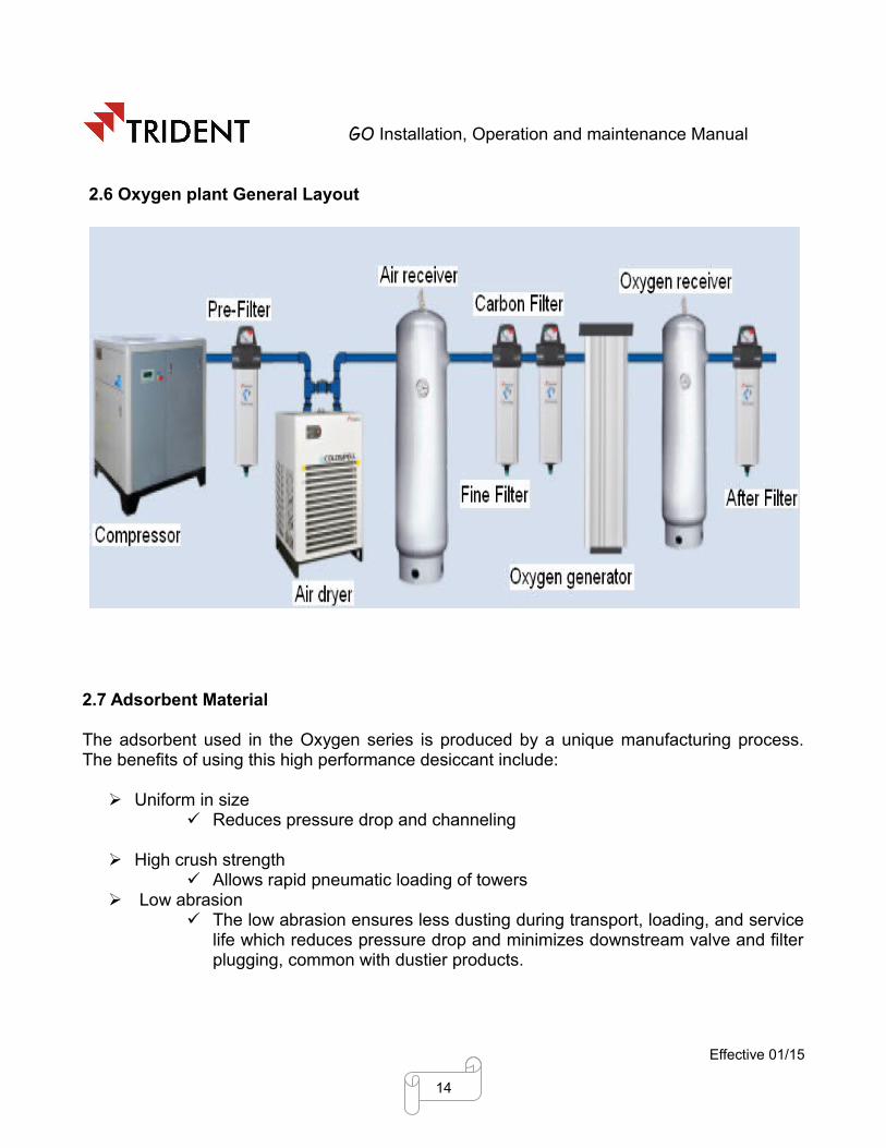
2.6 Oxygen plant General Layout
2.7 Adsorbent Material
The adsorbent used in the Oxygen series is produced by a unique manufacturing process. The benefits of using this high performance desiccant include:
Uniform in size Reduces pressure drop and channeling
High crush strength Allows rapid pneumatic loading of towers
Low abrasion The low abrasion ensures less dusting during transport, loading, and service
life which reduces pressure drop and minimizes downstream valve and filter plugging, common with dustier products.
Effective 01/15
14

GO Installation, Operation and maintenance Manual
3. GO DETAILED PARTS AND FUNCTIONS
Effective 01/15
15

GO Installation, Operation and maintenance Manual
Effective 01/15
16

GO Installation, Operation and maintenance Manual
Effective 01/15
17
1 Desiccant Tower2 Air Receiver3 Oxygen Receiver4 Air Dryer5 Inlet feed air valve (V-1)6 Exhaust valve (V-2)7 Control Panel 8 Muffler9 Pressure Regulator 10 Bacterial Filter
11 Ball valve12 Pressure indicator 13 Non Return Valve(V-3)14 Oxygen Sensor 15 Pre-Filter 16 Fine Filter17 Carbon Filter 18 After Filter 19 Pressure equalization valve (v-4)20 Pressure relief valve

GO Installation, Operation and maintenance Manual
`
Effective 01/15
18
1. Air outlet from air receiver to towers (Aluminium connection)
2. Air outlet from dyer to Air receiver (Aluminium connection)
3. Oxygen outlet from tower to Oxygen receiver (Copper connection)

GO Installation, Operation and maintenance Manual
Effective 01/15
19
1.Air outlet from dryer 2. Air inlet to receiver
3. Air outlet from receiver 4. Air inlet to Adsorber tower
5.Oxygen outlet from Adsorber tower 6. Oxygen inlet to oxygen receiver
7.Oxygen outlet to the user

GO Installation, Operation and maintenance Manual
Effective 01/15
20

GO Installation, Operation and maintenance Manual
3.1 Process flow diagram
Effective 01/15
21

GO Installation, Operation and maintenance Manual
3.2 Parts DescriptionOxygen Generator consists of,
2 Adsorbent towers filled with Zeolite 1 Air dryer 1 Air receiver 1 Pre filter 1 Fine filter 1 Carbon filter 1 after filter 1 Bacterial filter 1 Inlet feed air solenoid pilot valves 1 electronic control valve 2 Mufflers Electronic auto drain valves 1 Pressure equalization valve Pressure regulators Pressure gauges 2 Non return valves Oxygen sensor 2 Ball valves 2 exhaust solenoid pilot valves PLC Control panel Pressure relief valve
Adsorbent TowersTrident oxygen plant has 2 Adsorber towers and which contains the Zeolite Molecular
Sieves along with Activated alumina. This mixed desiccant bed adsorbs nitrogen, and concentrates oxygen from the air during drying cycle. Pressure gauges are fitted on this towers to indicate the tower pressure and there is provision for refilling the desiccant.
Air dryerMoisture in compressed air used in oxygen plant causes problems in the operation of
the desiccant beds as well as solenoid valves and can adversely affect the process and product being manufactured. In order to avoid the above said problem and to supply the dry air an air dryer is required in this plant. Trident make Coldspell refrigeration dryer eliminates any water vapour remaining in the compressed air coming at the outlet of the compressor house. The dryers have been designed for nominal standard inlet conditions as per ISO 7183 in order to obtain a dew point under pressure of +3oC to +7oC.
Air receiverAir receiver is connected in between the Air dryer and Adsorbent towers. This air
Effective 01/15
22

GO Installation, Operation and maintenance Manual
receiver acts as a accumulator and the air supplied to this receiver must be dry air.
Pre-FilterThis filter avoids dust, dirt, foreign materials and moisture before entering into the
molecular sieves bed and damaging the working. Trident make pre-filter(5micron) is used in this plant.
Fine filterThis filter avoids dust, dirt, foreign materials and moisture before entering into the
molecular sieves bed and damaging the working. Trident make fine-filter(1micron) is used in this plant.
Carbon filterThis filter is used to remove oil and hydrocarbon vapour from the compressed air
stream before get into the desiccant bed. Trident make carbon filter(0.01micron) is used in this plant.
After filterThis filter avoids the desiccant particles from the adsorbent towers coming with the
oxygen after production. Trident make fine-filter(1micron) is used in this plant.Bacterial filter
Bacterial filters provide effective protection against various types of particles including bacteria, viruses, and moisture droplets in the oxygen out from the plant. This filters help to protect the patient, and the breathing circuit from contamination.
Inlet feed air solenoid pilot valvesThis valves allows the inlet feed air between the two adsorbent towers during drying
phase. Controls signals for valve operation is taken from the control panel and the pilot air required for this valve is taken from the air receiver.
Electronic control valveThese valves open for a period of when the absorber is pressurized to deliver oxygen
to the oxygen receiver for use.
MufflersMufflers are used for reducing the amount of noise emitted by the exhaust of the waste
gases coming out from the adsorbent towers during regeneration phase.
Electronic auto drain valvesElectronic auto drain valve (EDV) automatically removes condensate from the filters.
Effective 01/15
23

GO Installation, Operation and maintenance Manual
Pressure equalization valveAfter pressurization cycle on one of the absorbers, the purge valve will open for a
period and pressure equalization between the adsorber towers will take place.
Pressure regulatorsThe air pressure regulator controls the inlet air pressure before entering into the
adsorber tower in the inlet side and control the delivery oxygen pressure at delivery side.
Pressure gaugesThese gauges indicates the air pressure inside the adsorbent towers and receiver.
Non return valvesThese valves prevents the back flow of oxygen into the adsorbent towers.
Oxygen sensorThis sensor is used to indicate the product purity in terms of %of oxygen from the
oxygen generator.
Ball valvesThese valves are used to open and shut off the inlet and product outlet from the
receivers based on the requirement.
Exhaust solenoid pilot valvesThis valves allows the waste air from the two adsorbent towers during regenerating
phase. Controls signals for the valve operation is taken from the control panel and the pilot air required for this valve is taken from the air receiver.
PLC Control panelThe PLC (Programmable Logic Controller) process the inputs and outputs ) to and from
the system components and communicates with the touch screen.
Pressure relief valve This valve is in place to ensure that the pressure in the vessels does not exceed safe system working pressure. It will only open in the event of a serious malfunction. It is fitted in all vessels.
3.3 PACKAGING AND HANDLINGUnpacking
• Check for any obvious damage to the carton or its contents. If damage is evident, notify the carrier, or your local dealer.
• Remove all loose packing from the carton.• Carefully remove all the components from the carton. The onsite oxygen plant
Effective 01/15
24

GO Installation, Operation and maintenance Manual
packaging contains the following parts,. If any parts are missing, please contact your equipment provider.
2 Adsorbent towers filled with Zeolite 1 Air dryer 1 Air receiver 1 Pre filter 1 Fine filter 1 Carbon filter 1 after filter 1 Bacterial filter
Inspection• Inspect/examine exterior of the oxygen plant and accessories for damage. Inspect all
components.Storage
• Store the repackaged oxygen plant in a dry area.
4. DESCRIPTION OF OPERATION The oxygen generator works on the PSA principle. The mixed bed desiccant
adsorbs moisture and Nitrogen from the compressed air for generating the oxygen. For proper removal of moisture and Nitrogen from the wet air regeneration of the desiccant is required. Regeneration is achieved by means of allowing a part of the the oxygen from the supply outlet.
Cycle of OperationsThe oxygen generator works based on the following phases,
➔ Drying ➔ Pressure Equalization➔ Depressurization➔ Regeneration➔ Re-pressurization
Drying cycleThe compressed wet air flows through the pre filter. The water particles get filtered by
the filter. The filtered air flows in to the adsorber tower filled with activated alumina where it loses all the moisture to the alumina. Purified (Moisture and oil free) air further passing through the Molecular Sieves (Zeolite type). The sieves selectively adsorbs nitrogen, allowing oxygen to pass through at the desired purity level.
Effective 01/15
25

GO Installation, Operation and maintenance Manual
Pressure Equalization cycleAt the end of drying cycle the second adsorber tower is ready for the next drying cycle
so in order to re-pressurize the tower to drying pressure by means of inlet air it take so much time to save that energy the air in the tower 1 is fed in to the second tower and the pressures are equalized.
DepressurizationAfter drying for the preset cycle time, the desiccant bed will be saturated with moisture
and nitrogen. For successful removal of moisture and nitrogen in the next cycle, this moisture and nitrogen is to be removed from the desiccant. This removal of moisture cycle starts with depressurization. In this cycle air inside the tower is vent out by the depressurization valve. The pressure is expanded to atmospheric pressure. The sudden depressurization brings out nitrogen molecules trapped in the sieves pores to the surface of the beads
Regeneration Cycle In order to remove the moisture and nitrogen during regeneration cycle. Small portion
of oxygen from the drying tower is passes over the sieves through the regeneration orifice. This results in complete regeneration of Molecular Sieves and ready for the next cycle.
Re-pressurization cycleAt the end of drying cycle the second adsorber tower is ready for the next drying cycle
so re-pressurization of the tower2 to drying pressure is necessary this is achieved by allowing the inlet feed air to the adsobent tower.
WORKING
✗ Wet dirt atmospheric air is compressed in the compressor.✗ The air coming from the compressor is first fed into the inlet Pre-Filter, here the
impurities present itself and water particles are removed.✗ After that in order to remove the water vapor present in the air it is allowed to flow
through the refrigerant air dryer, where 2 to 7 deg c pressure dew point is achieved.✗ This dry air is stored in the air receiver under pressure. ✗ On the first cycle drying phase dry air is allowed to adsorbent tower by means of inlet
valve through the fine filter and carbon filter, Where the foreign materials and carbon particles are removed from the air.
✗ The compressed dry air flowing through mixed bed tower 1 is selectively adsorbs the nitrogen and delivers the oxygen enriched air to the oxygen receiver.
✗ Where the oxygen is stored under pressure.✗ At this time the tower 2 is in regeneration phase.✗ A small portion of the oxygen enriched air is expanded to near atmospheric pressure
by passing through the purge orifice. Expansion of this oxygen gas to near-atmospheric pressure increases the ability of the purge air to strip the previously
Effective 01/15
26

GO Installation, Operation and maintenance Manual
adsorbed nitrogen from desiccant bed in tower 2. The absorbed gases exhausts through the opened two-way purge valve.
✗ From the oxygen receiver the oxygen is taken to the user end through the after filter and bacterial filter.
The automatic cycling of the adsorption and desorption between the two beds enables the continuous production of oxygen.
Trident make oxygen generator's have a failure alarm system.In the touch screen display the alarms indicates the following,
• If the purity of the oxygen drops under the rated purity level.• If the pressure of the oxygen outlet drops under the rated pressure.
Warning
Failure to follow these instructions can lead to serious injury or death.This dryer should be only be used for drying filtered, compressed air.
Ensure inlet air to this air dryer is filtered.
Only experienced and licensed electricians that are properly trained in compressed air and separation systems should service or repair Trident products. Before start-up or performing any maintenance on any Trident gas separation product like oxygen and nitrogen generator air dryer, filter, drain system, or other equipment, you must first turn off and disconnect all electrical power and service to the equipment at the main disconnect switch. Also, be sure to bypass and depressurize the dryer to 0 PSIG. Do not start or operate the dryer if there is a leak. Make sure the dryer’s protection rating is applicable to the installation conditions. Do not operate the generator at pressures and/or temperatures above the maximum allowable marked on the data label. Likewise, verify that incoming voltage matches the voltage marked on the data label. Do not lift the generator by its piping or control box or drop the generator. Doing so may damage the equipment.
Effective 01/15
27

GO Installation, Operation and maintenance Manual
5. INSTALLATION Safety
Oxygen Generator are intended for the separation of compressed air from nitrogen to oxygen. Under no circumstance should they be used to dry other gases.
The adsorbents used are non-toxic. However, they may cause respiratory problems if they are inhaled in dust form. The use of a dust mask is sufficient to protect personnel.
Trident make Oxygen generators are pre - Assembled one. In the case of inbuilt air compressor there is no need for any connections. As in case of without air compressor in the unit proper pipe connection should be given, for the pipe sizes refer the models.
Installation Site and Connections
Install the generator in a closed clean, dry room protected from freezing. Access to the room should be restricted to personnel qualified in maintenance and
operation. The room must be adequately ventilated. The generator must not be directly exposed to sources of heat. The temperature of the room must not exceed 43°C/109°F. Make sure that the generator is not near any equipment which does not comply with
the electromagnetic compatibility directives and which may degrade generator operation.
There must be a minimum distance of 3 feet between the dryer and any other equipment which uses electricity.
Ensure that the generator is installed in the vertical position. Generator should be secured by bolting it down. Install a system of by-pass valves between the Generator inlet and outlet so the dryer
can be serviced without having to interrupt the compressed air supply from the circuit (see diagram above). The upstream and downstream valves must be closed during installation.
Connect a drain line to the Pre-filter auto drain outlet. Check for leaks after all connections have been made. Always pressurize generator before power up.
Electrical Connections Provide separate MCB connections for both the air dryer and Oxygen Generator Connect the electrical power cable to an 85 - 265 V, single phase, 50 Hz grounded
power supply.
Effective 01/15
28

GO Installation, Operation and maintenance Manual
6. HOW TO START THIS GENERATOR?
When you complete the installation as described in the previous section, the oxygen generator is ready for easy start-up and operation.
Initial Start Up
✔ Make sure the ON/OFF switch on the control panel is set to OFF.✔ Connect the generator with the power circuit and Make sure the power circuit
cannot be turned off accidentally.
Note: If the power is turned off unexpectedly, the unit will stop cycling. If your application is using oxygen when the power is off, the oxygen receiver will depressurize.
✔ Fully close the ball valve placed before the adsorber tower.✔ Fully close the ball valve placed after the bacterial filter.✔ Turn ON the compressor & air dryer, and allow the air receiver to pressurize.✔ Now adjust the pressure regulator placed before the inlet ball valve to set 5 bar
pressure. ✔ Now switch ON the power circuit of the generator. In the control panel touch
screen display press the cycle ON button.✔ Now gradually open the inlet ball valve and allow the air to enter into the
generator.✔ In the control panel display go to the operator screen on that you can see the
Oxygen purity and pressure.✔ It takes some time to pressurize the oxygen receiver to 4.5 bar. After reaching
the oxygen pressure more the 4.5 bar in the display open the outlet ball valve and the rated flow of the generator's model.
Note: Don't Overdraw the oxygen more than as specified in the generator's model. Because its lead to
1. Drop in oxygen purity2. Drop in oxygen pressure
Shutting Down the generator
• If there is an emergency press Emergency switch off button on the control panel.
• For Regular shut down during maintenance and below rated usage of the generator follow the procedure below:
Effective 01/15
29
GO Installation, Operation and maintenance Manual
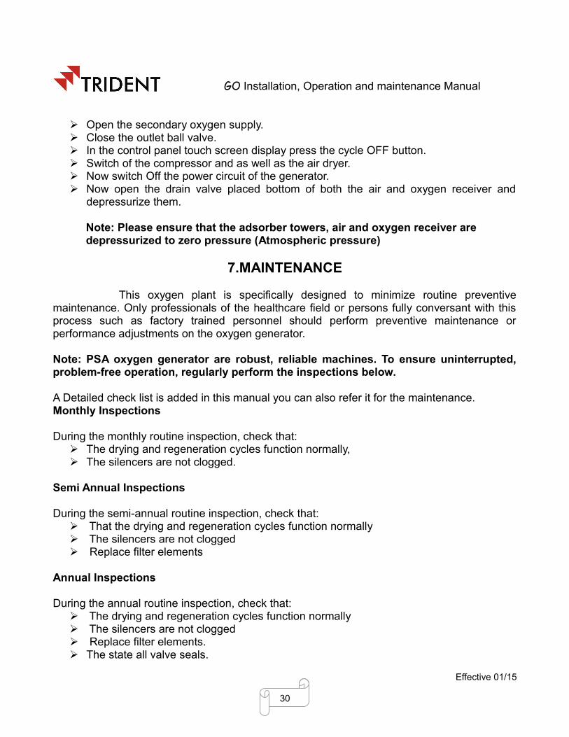
Open the secondary oxygen supply. Close the outlet ball valve. In the control panel touch screen display press the cycle OFF button. Switch of the compressor and as well as the air dryer. Now switch Off the power circuit of the generator. Now open the drain valve placed bottom of both the air and oxygen receiver and
depressurize them.
Note: Please ensure that the adsorber towers, air and oxygen receiver are depressurized to zero pressure (Atmospheric pressure)
7.MAINTENANCE
This oxygen plant is specifically designed to minimize routine preventive maintenance. Only professionals of the healthcare field or persons fully conversant with this process such as factory trained personnel should perform preventive maintenance or performance adjustments on the oxygen generator.
Note: PSA oxygen generator are robust, reliable machines. To ensure uninterrupted, problem-free operation, regularly perform the inspections below.
A Detailed check list is added in this manual you can also refer it for the maintenance.Monthly Inspections
During the monthly routine inspection, check that: The drying and regeneration cycles function normally, The silencers are not clogged.
Semi Annual Inspections
During the semi-annual routine inspection, check that: That the drying and regeneration cycles function normally The silencers are not clogged Replace filter elements
Annual Inspections
During the annual routine inspection, check that: The drying and regeneration cycles function normally The silencers are not clogged Replace filter elements. The state all valve seals.
Effective 01/15
30

GO Installation, Operation and maintenance Manual
Note: During the entire operation, the compressor and the generator must be shut down. It is recommended for all personnel who are in the presence of the desiccant to wear dust masks.
Changing the Desiccant
Bypass the oxygen supply into the secondary line. Disconnect the power supply to the generator. Make sure the inlet air supply to the generator is closed. Depressurize the pressure in both towers Loosen the dummy present in the tower bottom desiccant port Remove the old desiccant and replace new desiccant one.
Replacing the filter element
1. Before replacing the element we need to check whether the replacement is required.
Effective 01/15
31

GO Installation, Operation and maintenance Manual
2.During the change Signal we need to prepare for the filter element change. The filter element must be changed at change stage indication.
3. If you are replacing a coalescing filter element, remove and discard the gasket where the top of the filter element connects to the filter housing.
4.If you are replacing a coalescing filter element, make sure a black gasket is attached to the top of the new element.
4. Check for leaks after all connections have been made. Do not start or operate the filter with leak.
5. If the Electronic Adjustable drain valve connection have been installed, must to ensure the input voltage supply.
Effective 01/15
32

GO Installation, Operation and maintenance Manual
8.TROUBLESHOOTINGThe following problems may exists while using the oxygen plant. This section will give
details about the problems and there remedy. Troubleshooting tree will help you to solve the problems
General troubleshootingBefore reviewing the troubleshooting chart, the following steps may be useful to isolate
any malfunctions:✗ Turn the generator on. If unit does not turn on, refer to troubleshooting chart.✗ Make sure all filters are clean.✗ Make sure the unit is cycling properly. If the unit is not cycling properly, refer to
troubleshooting chart.✗ If generator is not meeting specifications, make sure that the unit is leak free by testing
all tubing connections and fittings with leak testing solution. Repair all leaks by tightening connections and fittings.
✗ Review troubleshooting chart to isolate and repair any other malfunctions.`
LEDS not GlowingCheck the power supply connection and tension
Tower Status LED not changing✔ Change the controller
LEDS Status Change but Tower not Switching✔ Check coil connection at DIN and terminal connector in the controller✔ Check the solenoid valve
No Purging✔ Check the solenoid valve✔ Check the exhaust valve✔ Clean the silencer (muffler)Continuous Purging at Tower 1A – Shuttle not closing✔ Check pilot air for exhaust valve✔ Check exhaust valve piston stuck
High Purge Loss✔ Check outlet shuttle closing✔ Check for silencer choke
High Pressure Drop across Generator✔ Pre-filter may be clogged. Check and replace filter elements.✔ Check whether the generator is being overflowed.
Effective 01/15
33

GO Installation, Operation and maintenance Manual
8.1 TROUBLESHOOTING TREE
1. Purity problem
Effective 01/15
34
Purity down
No
Random change Yes
Abrupt change
No
No
Sensor Problem
Yes No
Calibrate (or) Change
Display problem
No
Yes
Repair (or)Change
Yes
Turn to next Page
Yes

GO Installation, Operation and maintenance Manual
Effective 01/15
35
Turn to next Page
Check proper phase change
Drying Regenerating
Switch on the generator
Purity Problem
No
Leaks present Remove Leaks
Leak Test
Check air flow from Air receiver and adjust it
Continued from last page
SupplyAir flow problem
Yes
Yes No
Yes
No

GO Installation, Operation and maintenance Manual
Effective 01/15
36
Functional Check on Inlet Feed air valve
Continued from last page
Repair or Replace it
Is Malfunction ??Yes
No
Functional Check on Exhaust valve
Is Malfunction ??Repair or Replace it
Functional Check on Pressure Equilization valve
Turn to next Page
Yes
No

GO Installation, Operation and maintenance Manual
Effective 01/15
37
Continued from last page
Is Malfunction ??Repair or Replace it
Dew point check on Air Dryer
Is dew point is 3 – 7 ºC
Repair / Service the Air dryer
Functional test
Purity ProblemNo
Yes
YesNo
Turn to next Page

GO Installation, Operation and maintenance Manual
Effective 01/15
38
Change Desiccant
OK
Clean all Air Filters
Continued from last page
Purity Problem
Yes
No
Purity check

GO Installation, Operation and maintenance Manual
2.Low Operating Pressure
Lower than normal operating pressure may indicate any of the following,
• A restriction in the suction air intake filter, which limits the amount of air pass through it to the generator. Clean the air filters free from foreign materials.
• An improperly operating circuit board or solenoid valve. Confirm that the circuit board and solenoid valves function properly.
• A leak in the unit, which allows system pressure to escape. Perform Leak test in the unit.
• A compressor with reduced output. Ensure that the oxygen concentration level at the desired liter flow is within Trident's specifications. If it is below specifications, replace or repair the compressor.
3. High Operating PressureHigher than normal operating pressure may indicate any of the following.
• A restrictive muffler, which does not allow the waste (purge) gas to exit the system freely. Operate the unit with the muffler disconnected to see if the operating pressure returns to normal.
• An improperly operating circuit board or solenoid valve. Confirm that the circuit board and solenoid valves function properly.
• A restrictive diffuser, which does not allow the inlet feed air as well as exhaust air from the generator. Check the diffuser and correct it.
• Contaminated sieve beds. Change the sieve beds.
Effective 01/15
39

GO Installation, Operation and maintenance Manual
9. PLC CONTROL PANEL USAGE The following steps will explain about, how to use the control panel touchscreen display.
PLC Control panel
Control panel display
Effective 01/15
40

GO Installation, Operation and maintenance Manual
HOME SCREEN
BUTTONS:M/C ON - USED TO START THE PROCESS.M/C OFF - USED TO STOP THE PROCESS.MENU - NAVIGATION TO MENU PAGE.
MENU PAGE
BUTTONS:SETTINGS - NAVIGATION TO SETTINGS PAGE PASSWORD
SCREEN.OPERATOR SCREEN - NAVIGATION TO OPERATOR SCREEN PAGE.ALARM - NAVIGATION TO ALARM PAGE.
Effective 01/15
41

GO Installation, Operation and maintenance Manual
OPERATOR SCREEN
BUTTONS:MENU - NAVIGATION TO MENU PAGE.NEXT - NAVIGATION TO RUN HOURS VIEW PAGE.
Oxygen pressure in bar g and Oxygen purity in % will be displayed. Energy saving will blink when the machine is in energy saving mode.
ALARM
BUTTONS:MENU - NAVIGATION TO MENU PAGE.
This page provides the list of alarms occurred in the machine.
Effective 01/15
42

GO Installation, Operation and maintenance Manual
RUN HOURS
BUTTONS:
MENU - NAVIGATION TO MENU PAGE.
BACK - NAVIGATION TO OPERATOR SCREEN PAGE.
Displays the machine’s total running hours.
EMERGENCY ALARM
BUTTONS:ESC – NAVIGATION TO HOME PAGE.
This page will be displayed when emergency button in the panel is pressed. When emergency stop button is pressed then the process will be stopped. To start the process check the condition of machine and release the emergency button and move to home page and press the M/C ON button.
Effective 01/15
43

GO Installation, Operation and maintenance Manual
ALARM BANNER
When any alarm present on the machine that will be displayed on the alarm banner. Alarm banner is at bottom line on every page.
NOTES
✗ Emergency stop button is used to stop the process during risky conditions.✗ Control on selector is used to power up the controller.✗ Alarm indication will be on when oxygen purity & oxygen pressure are less than the
setpoint.✗ Alarms configured on the machine are emergency stop, filter element replacement,
bacterial filter autoclave, oxygen purity low, oxygen pressure low.
Effective 01/15
44

GO Installation, Operation and maintenance Manual
CHECK LIST
Effective 01/15
45
Activities Frequency
Hourly Daily Weekly Monthly Half Yearly Yearly Whenever requiredCheck Compressor Pressure
Check Compressor oil level
Service compressor according to supplier instructions
Check Oxygen Pressure
Check rated oxygen flow
Check Oxygen Purity
Check Dew point at dryer outlet
Service Air dryer according to supplier instructions
Check Air Dryer condensate drain
Check Tower pressure
Check drain on all Filter
Replace all filter element
Check pressure in Air tank
Check pressure in Oxygen tank
Check Pressure safety valve
Calibrate all Pressure gauge
Calibrate Oxygen sensor
Check solenoid valves for corrosion
Check pipes / hoses
Replace desiccant

GO Installation, Operation and maintenance Manual
GO SPARES LIST
Effective 01/15
46
GO DETAILED SPARES CHANGING FREQUENCY
Spares Year1 Year2 Year3 year4 year5 Requirement
Keep 2Kg as spare
Compressor
Expansion valve Keep 1 as spare
Controller Keep 1 as spare
HP/LP sw itch Keep 1 as spare
Fine Filter (X)
Carbon Filter (A)
After Filter (Y)
Bacterial Filter
Inlet valve seal kit Keep 1 as spare
Exhaust valve seal kit Keep 1 as spare
Shuttle valve seal kit Keep 1 as spare
Solenoid valve (3/2 w ay) Keep 1 as spare
Desiccant
Pressure gauge Keep 1 as spare
Oxygen sensor
Pressure Transmitter
Pressure Regulator
Year 6
Year 7
Year 8
Year 9
Year 10
Whenever required
Gas Topup
Pre-Filter (P)
Air Dryer
Filters
Oxygen G
enerato
r

GO Installation, Operation and maintenance Manual
Effective 01/15
47

GO Installation, Operation and maintenance Manual
WARRANTYProducts of Trident Pneumatics Pvt Ltd are guaranteed to be free from defects in material and workmanship when installed and operated in accordance with the instructions outlined in the instruction manual.
Trident Pneumatics pvt. Ltd.'s obligation under this warranty shall be limited to repair or replacement (at the discretion of Trident) of defective goods returned to Trident Plant within one (1) year from the date of commissioning or 18 months from the date of invoicing which ever is occurring earlier.
Product :
Model :
Serial No. :
-----------------------------------Quality Assurance Dept
Trident Pneumatics Pvt Ltd5/232, K.N.G Pudur Road, Somayampalayam,
Coimbatore 641 108. Ph: 0422 2400492, 2401373Fax: 0422 2401376 e-mail: [email protected]
Website: www.tridentpneumatics.com
Effective 01/15
48

GO Installation, Operation and maintenance Manual
INSTALLATION & COMMISIONING REPORTPSA Type Oxygen Generator
Customer :
Contact person :
Designation :
Model :
Sl. No. :
Phone :
Fax :
(Please add any comments or remarks here found while unpacking)
1. INSTALLATION
a) Installation at : Before / After Air Dryer LED Glowing Yes / No
b) Inlet air Temperature : Normal / High Tower 1 and 2 Drying
Yes / No
c) Side clearance provided :
Yes / No Depressurizing Yes / No
d) Power Grounded : Yes / No Regeneration Yes / No
e) Oxygen Flow Outlet : Normal / Faulty Oxygen Purity:
Oxygen Pressure:f) Change over sequence :
Normal / Faulty
2. COMMISSIONINGInstallation Date of Completion
Commissioning Date of CompletionComments:Customer Installation Engineer
Signature & Name of Installing Engineer
Dealers Signature & Seal
Customer's Signature & Seal
Effective 01/15
49