Embed Size (px)
Citation preview
Rinnai Customer Care 1-800-621-9419 www.rinnai.us
Control-R™ Wi-Fi Module Installation Manual
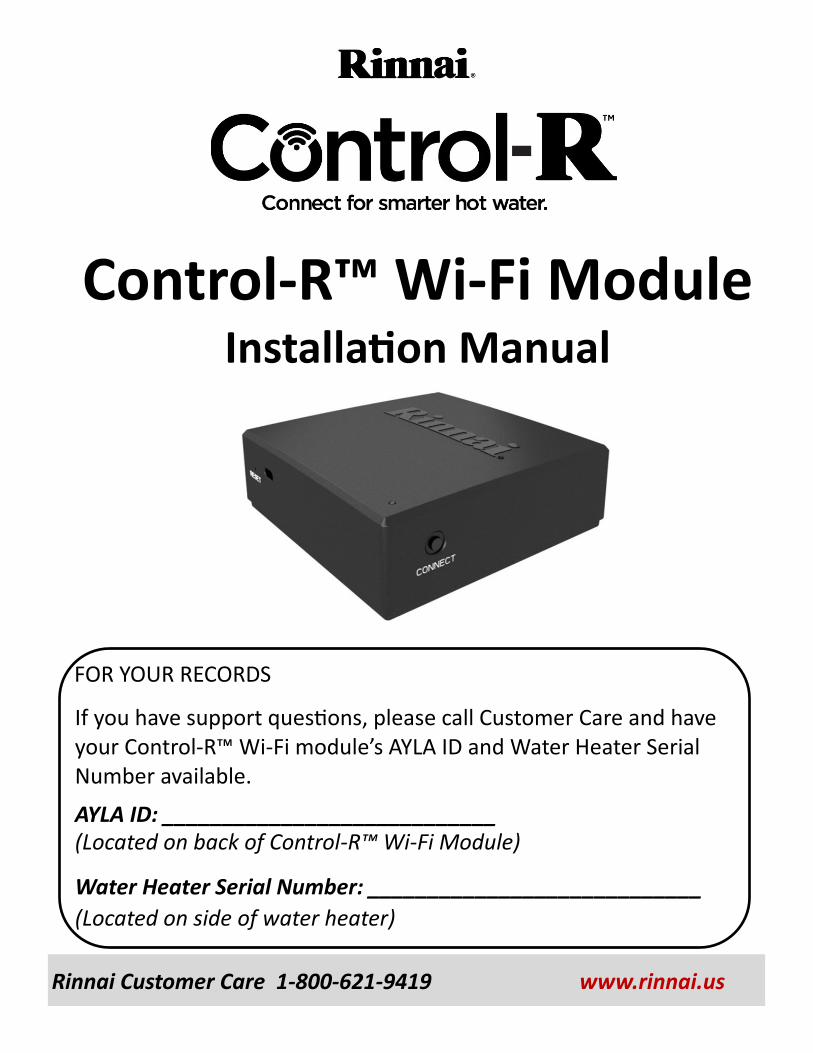
FOR YOUR RECORDS
If you have support questions, please call Customer Care and have your Control-R™ Wi-Fi module’s AYLA ID and Water Heater Serial Number available.
AYLA ID: ____________________________ (Located on back of Control-R™ Wi-Fi Module)
Water Heater Serial Number: ____________________________
(Located on side of water heater)
Rinnai® Control-R™ Wi-Fi Module Installation Manual 2
Thank You For Your Purchase
Thank you for purchasing the Rinnai® Control-R™ Wi-Fi Module (referred to as “module” throughout this manual). Before installing and operating the module, be sure to read these instructions to familiarize yourself with the module’s features and functionality.
Please Read and Save This Manual
Please read this manual and save for future reference.
If You Need Service
Please call Rinnai Customer Care at 1-800-621-9419 Monday to Friday between 8 AM to 8 PM EST. Please have the following information available: AYLA ID (Located on back of Control-R™ Wi-Fi Module) Water Heater Serial Number (Located on side of water heater)
FCC Part 15
This device complies with Part 15 of the FCC rules. Operation is subject to the following two conditions: This device may not cause harmful interference. This device must accept any interference received, including
interference that may cause undesired operation.
Rinnai® Control-R™ Wi-Fi Module Installation Manual 3
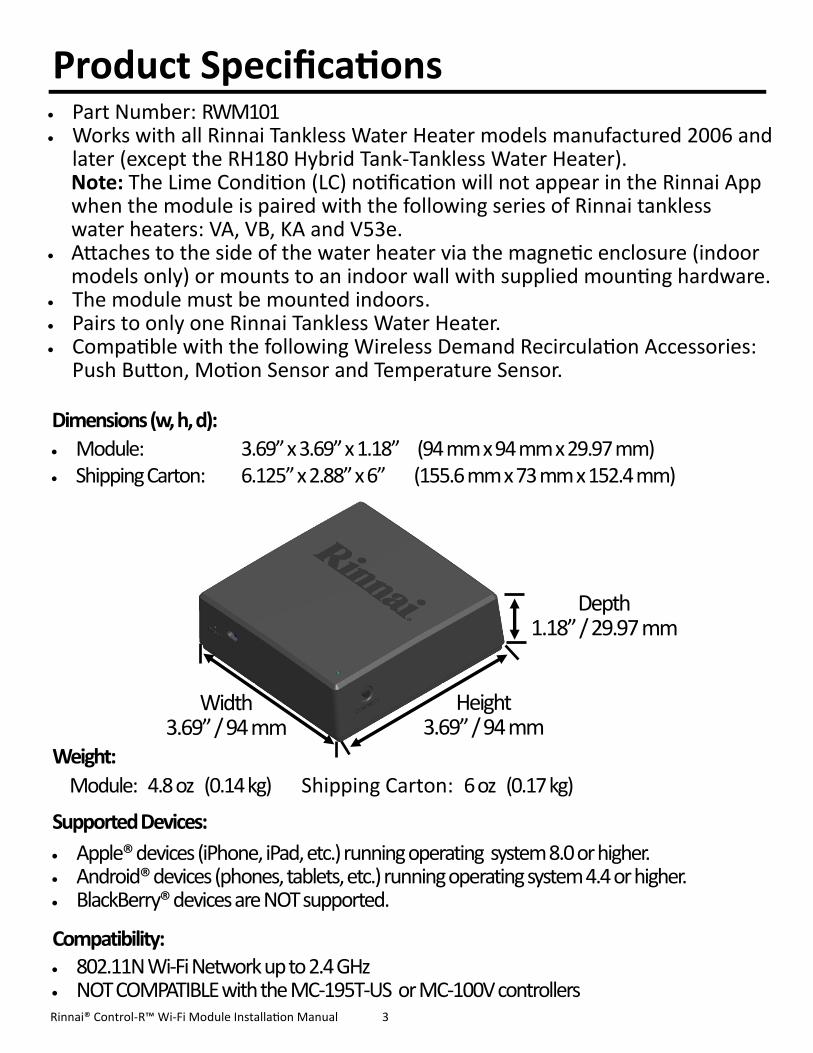
Dimensions (w, h, d):
Module: 3.69” x 3.69” x 1.18” (94 mm x 94 mm x 29.97 mm) Shipping Carton: 6.125” x 2.88” x 6” (155.6 mm x 73 mm x 152.4 mm)
Weight:
Module: 4.8 oz (0.14 kg) Shipping Carton: 6 oz (0.17 kg)
Supported Devices:
Apple® devices (iPhone, iPad, etc.) running operating system 8.0 or higher. Android® devices (phones, tablets, etc.) running operating system 4.4 or higher. BlackBerry® devices are NOT supported.
Compatibility: 802.11N Wi-Fi Network up to 2.4 GHz NOT COMPATIBLE with the MC-195T-US or MC-100V controllers
Width 3.69” / 94 mm
Height 3.69” / 94 mm
Depth 1.18” / 29.97 mm
Part Number: RWM101 Works with all Rinnai Tankless Water Heater models manufactured 2006 and
later (except the RH180 Hybrid Tank-Tankless Water Heater). Note: The Lime Condition (LC) notification will not appear in the Rinnai App when the module is paired with the following series of Rinnai tankless water heaters: VA, VB, KA and V53e.
Attaches to the side of the water heater via the magnetic enclosure (indoor models only) or mounts to an indoor wall with supplied mounting hardware.
The module must be mounted indoors. Pairs to only one Rinnai Tankless Water Heater. Compatible with the following Wireless Demand Recirculation Accessories:
Push Button, Motion Sensor and Temperature Sensor.
Product Specifications
Rinnai® Control-R™ Wi-Fi Module Installation Manual 4
Unpack System Contents Carefully unpack your system contents. If any part of the system appears damaged, do not attempt to use it. Contact Rinnai Customer Care (1-800-621-9419) or your authorized Rinnai Service Provider. WARNING: To avoid danger of suffocation, keep plastic bags out of the reach of children.
Check to be sure your system includes the following parts:
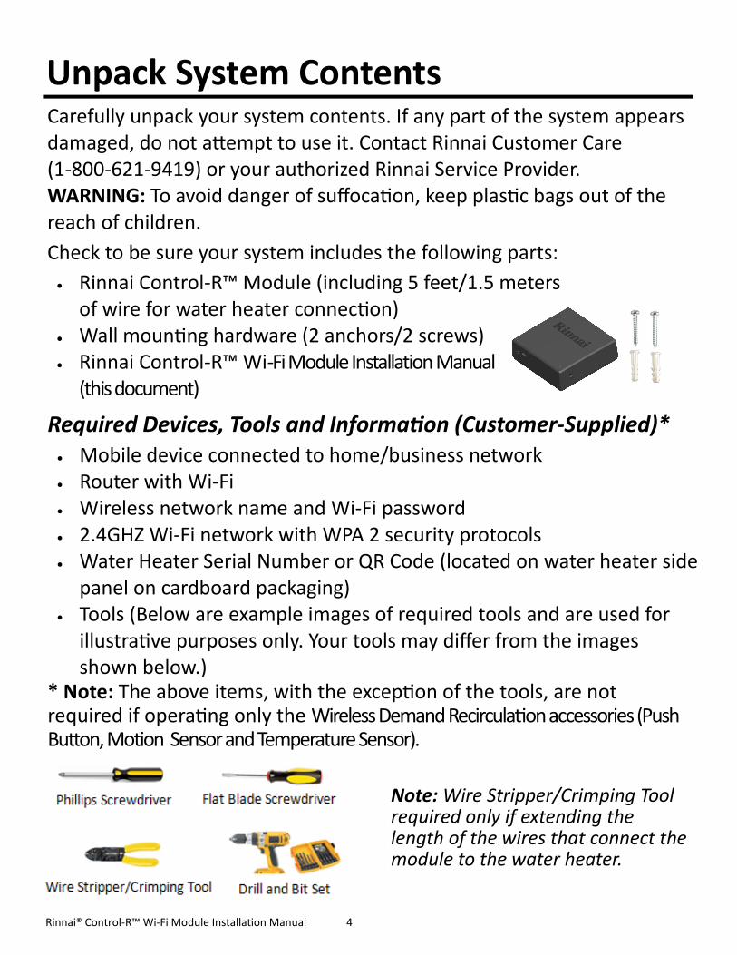
Rinnai Control-R™ Module (including 5 feet/1.5 meters of wire for water heater connection)
Wall mounting hardware (2 anchors/2 screws) Rinnai Control-R™ Wi-Fi Module Installation Manual
(this document)
Required Devices, Tools and Information (Customer-Supplied)* Mobile device connected to home/business network Router with Wi-Fi Wireless network name and Wi-Fi password 2.4GHZ Wi-Fi network with WPA 2 security protocols Water Heater Serial Number or QR Code (located on water heater side
panel on cardboard packaging) Tools (Below are example images of required tools and are used for
illustrative purposes only. Your tools may differ from the images shown below.)
* Note: The above items, with the exception of the tools, are not required if operating only the Wireless Demand Recirculation accessories (Push Button, Motion Sensor and Temperature Sensor).
Note: Wire Stripper/Crimping Tool required only if extending the length of the wires that connect the module to the water heater.
Rinnai® Control-R™ Wi-Fi Module Installation Manual 5
Use the following guidelines to select a location for the module. Choose a central location inside the home or business where the Wi-Fi
signal is strong. Note: If the water heater is located where the Wi-Fi signal is weak (such as basements or a mechanical room), the module is designed so that wiring can run up to 300 feet (91 meters) away from the tankless water heater to ensure a strong Wi-Fi signal (18-22 gauge wire is required).
Ensure that adequate space surrounds the module for service and support needs.
For outdoor water heaters, the module must be installed indoors. The module is magnetic and can be placed on the side of the Rinnai
tankless water heater (indoor models only) or mounted to a wall. See the next section for installation instructions.
Two options are available for installing the module:
Option 1: Magnetic Mount The module contains a strong magnetic backing and can easily be placed on the side of the water heater (indoor models only). Option 2: Wall Mount The module can be mounted to a wall with the supplied mounting hardware. Refer to the next section for steps on mounting the module to a wall.
Select a Location for Your Module
Install the Module
Rinnai® Control-R™ Wi-Fi Module Installation Manual 6
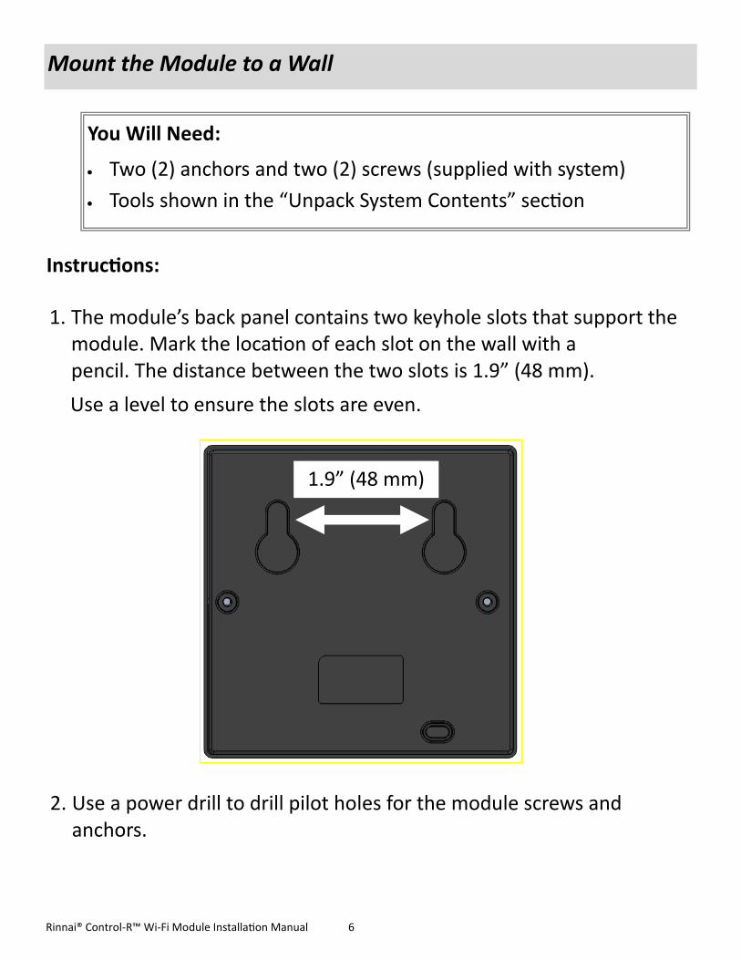
1. The module’s back panel contains two keyhole slots that support the module. Mark the location of each slot on the wall with a pencil. The distance between the two slots is 1.9” (48 mm).
Use a level to ensure the slots are even.
Instructions:
Mount the Module to a Wall
You Will Need:
Two (2) anchors and two (2) screws (supplied with system)
Tools shown in the “Unpack System Contents” section
2. Use a power drill to drill pilot holes for the module screws and anchors.
1.9” (48 mm)

Rinnai® Control-R™ Wi-Fi Module Installation Manual 7
5. Mount the module by placing
the keyhole slots (on back of
module) onto the screws.
3. Insert the supplied two wall
anchors into each hole until
they sit flush against the wall.
Mount the Module to a Wall (Continued)
4. Insert the supplied screws into
the anchors and fasten to the
wall leaving 1/4” exposed.

Rinnai® Control-R™ Wi-Fi Module Installation Manual 8
Turn off the electrical power supply by unplugging the power cord or by turning off the electricity at the circuit breaker. The temperature controller does not control the electrical power.
Turn off the gas at the manual gas valve, usually located immediately below the water heater.
Turn off the incoming water supply. This can be done at the isolation valve immediately below the water heater or by turning off the water supply to the building.
WARNING
1. Unplug the water heater. Note: Pressing the ON/OFF button on the controller does not completely power off the water heater.
2. Remove the four (4) screws located on the water heater cover. 3. Two (2) wires are attached to the bottom of the module. Place these
wires through the bottom opening of the water heater. 4. Attach each module wire to the terminals for control. 5. Replace and tighten the four (4) screws on the water heater cover.
To protect yourself from harm, follow the steps below before wiring the module:
Connect Module to Water Heater
Module Wires

Rinnai® Control-R™ Wi-Fi Module Installation Manual 9
1. Power on the water heater. The LED light on the module will blink yellow until boot-up is complete and will then turn solid red.
2. Download the Rinnai app from the Apple® Store or Google® Play Store.
3. Follow the steps in the Rinnai App to create an account and activate the module. Detailed instructions can be found online at www.rinnai.us/wifi. When setup is complete, the owner will have access to remotely monitor and control their Rinnai tankless water heater using their smart device.
Wi-Fi Setup Instructions (For Owner)
Pairing Instructions The module can be paired with the following Wireless Demand Recirculation Accessories: Push Button, Motion Sensor and Temperature Sensor.
For complete instructions on installing and pairing the Wireless Demand Recirculation Accessories to the module, refer to the instructions included in the accessory package.
The accessory installation instructions can be viewed online at www.rinnai.us/wifi
This Section Must be Performed By the Water Heater Owner (Homeowner/Business Owner)
Owner Instructions:
LED light

Rinnai® Control-R™ Wi-Fi Module Installation Manual 10
Color Blink Frequency State / Condition Duration
YELLOW Solid Start of Boot-up Sequence
Until next state change
RED Solid Error Condition / Not Provisioned
Until next state change
RED 0.5 Hz
On 1 second, Off 1 second
Wifi Provisioned, but No IP Address Yet
Until IP address obtained
GREEN Solid ZigBee* Pairing Mode Active
Until next state change:
Timeout or successful ZigBee join
GREEN 0.5 Hz
On 0.25 seconds, Off 0.25 seconds
ZigBee* Join Success 2 seconds
BLUE 2 Hz
On 0.25 seconds, Off 0.25 seconds
Wi-Fi Network Successfully Joined
Until next state change:
Cloud service connection
BLUE 0.5 Hz
On 1 second, Off 1 second
Attempting Gateway Registration with Cloud
Service
Until next state change:
Successful registration with Cloud Service
BLUE SOLID Ready to Use / Normal Operation
Until next state change
PURPLE 0.5 Hz
On 1 second, Off 1 second
Lost Connection to Wi-Fi Network
Until connection is re-established
PURPLE SOLID Lost Connection to Internet
Until connection is re-established
WHITE .5 Hz
On 1 second, Off 1 second
Factory Reset Mode Possible
Until button is released
LED Color Codes
* ZigBee is a wireless technology that is used for remote control and sensor applications. Zigbee is used for device-to-device communication, such as Rinnai’s recirculation accessories and Control-R™ Wi-Fi Module.
Rinnai® Control-R™ Wi-Fi Module Installation Manual 11
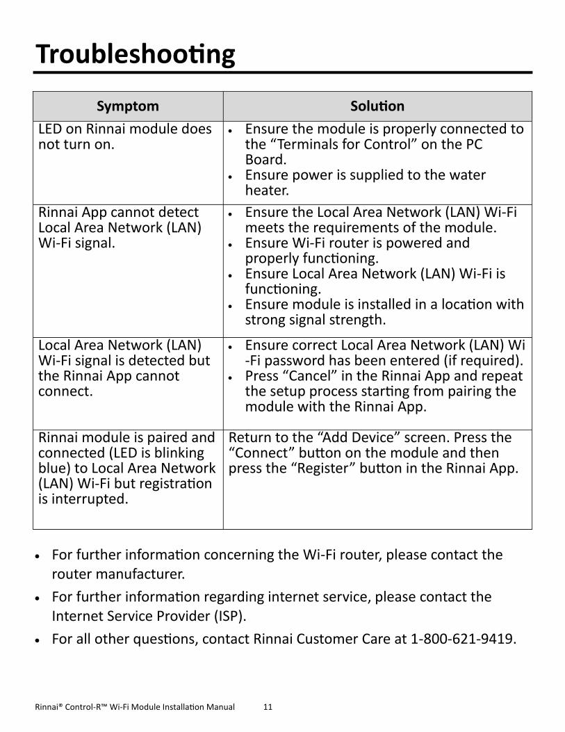
Symptom Solution
LED on Rinnai module does not turn on.
Ensure the module is properly connected to the “Terminals for Control” on the PC Board.
Ensure power is supplied to the water heater.
Rinnai App cannot detect Local Area Network (LAN) Wi-Fi signal.
Ensure the Local Area Network (LAN) Wi-Fi meets the requirements of the module.
Ensure Wi-Fi router is powered and properly functioning.
Ensure Local Area Network (LAN) Wi-Fi is functioning.
Ensure module is installed in a location with strong signal strength.
Local Area Network (LAN) Wi-Fi signal is detected but the Rinnai App cannot connect.
Ensure correct Local Area Network (LAN) Wi-Fi password has been entered (if required).
Press “Cancel” in the Rinnai App and repeat the setup process starting from pairing the module with the Rinnai App.
Rinnai module is paired and connected (LED is blinking blue) to Local Area Network (LAN) Wi-Fi but registration is interrupted.
Return to the “Add Device” screen. Press the “Connect” button on the module and then press the “Register” button in the Rinnai App.
Troubleshooting
For further information concerning the Wi-Fi router, please contact the router manufacturer.
For further information regarding internet service, please contact the Internet Service Provider (ISP).
For all other questions, contact Rinnai Customer Care at 1-800-621-9419.
100000447
9/2016