Embed Size (px)
Citation preview
University of Pennsylvania
SysMLOODA approach to Systems Engineering
University of Pennsylvania
Goals
• Appreciating the science of Architecture• Issues involved with RT System Arch.• Take a Look at a modeling language • Peek into the future for the trends in Indus.• Get a feel for the role that an architect
plays in the development process
University of Pennsylvania
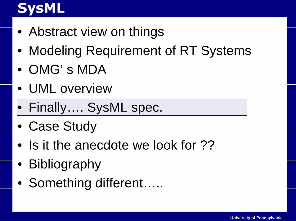
• Abstract view on things• Modeling Requirement of RT Systems• OMG’ s MDA• UML overview• Finally…. SysML spec.• Case Study• Is it the anecdote we look for ??• Bibliography• Something different…..
University of Pennsylvania
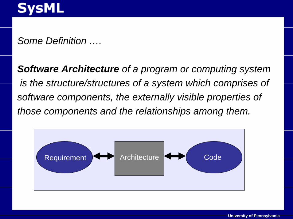
Some Definition ….
Software Architecture of a program or computing systemis the structure/structures of a system which comprises ofsoftware components, the externally visible properties ofthose components and the relationships among them.
Requirement CodeArchitecture
University of Pennsylvania
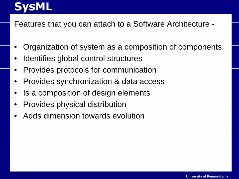
Features that you can attach to a Software Architecture -
• Organization of system as a composition of components• Identifies global control structures • Provides protocols for communication• Provides synchronization & data access• Is a composition of design elements• Provides physical distribution • Adds dimension towards evolution
University of Pennsylvania
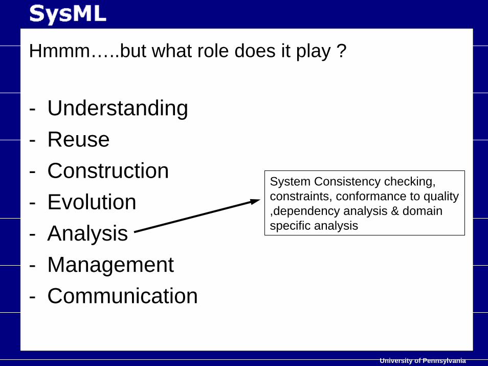
Hmmm…..but what role does it play ?
- Understanding- Reuse - Construction- Evolution- Analysis- Management- Communication
System Consistency checking, constraints, conformance to quality ,dependency analysis & domain specific analysis
University of Pennsylvania
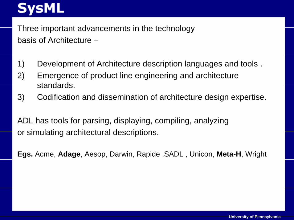
Three important advancements in the technologybasis of Architecture –
1) Development of Architecture description languages and tools .2) Emergence of product line engineering and architecture
standards.3) Codification and dissemination of architecture design expertise.
ADL has tools for parsing, displaying, compiling, analyzingor simulating architectural descriptions.
Egs. Acme, Adage, Aesop, Darwin, Rapide ,SADL , Unicon, Meta-H, Wright
University of Pennsylvania
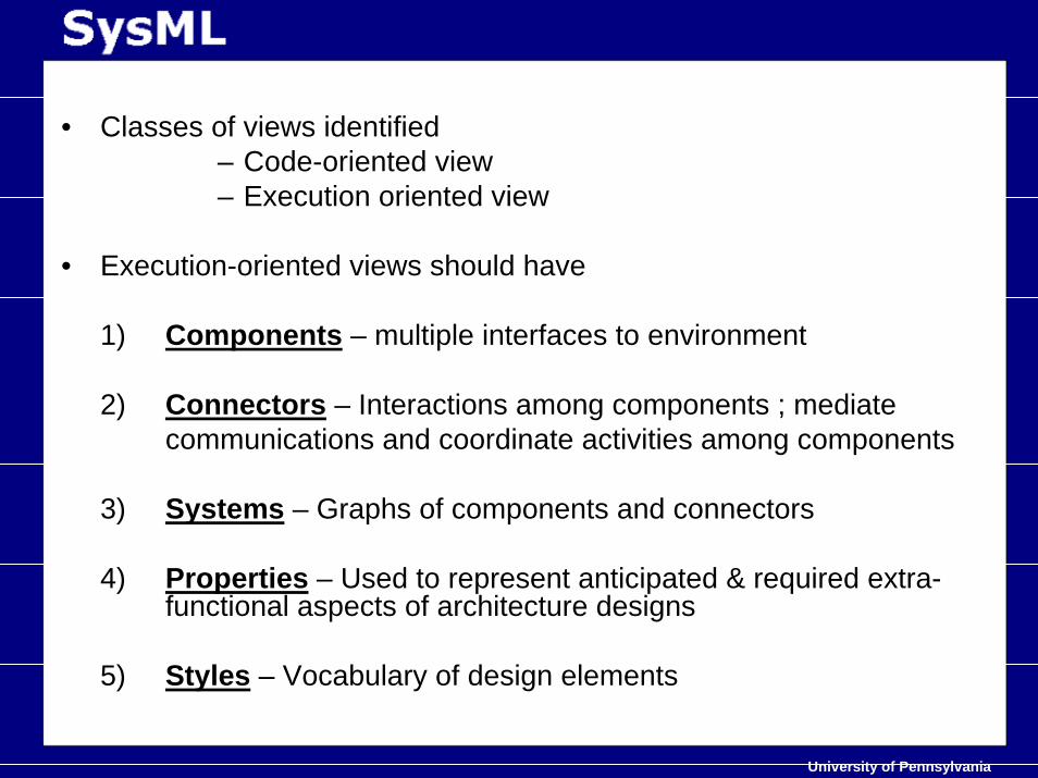
• Classes of views identified– Code-oriented view – Execution oriented view
• Execution-oriented views should have
1) Components – multiple interfaces to environment
2) Connectors – Interactions among components ; mediatecommunications and coordinate activities among components
3) Systems – Graphs of components and connectors
4) Properties – Used to represent anticipated & required extra-functional aspects of architecture designs
5) Styles – Vocabulary of design elements
University of Pennsylvania
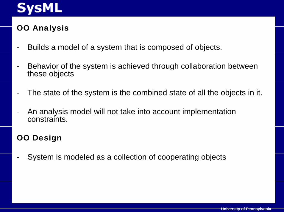
OO Analysis
- Builds a model of a system that is composed of objects.
- Behavior of the system is achieved through collaboration betweenthese objects
- The state of the system is the combined state of all the objects in it.
- An analysis model will not take into account implementation constraints.
OO Design
- System is modeled as a collection of cooperating objects
University of Pennsylvania
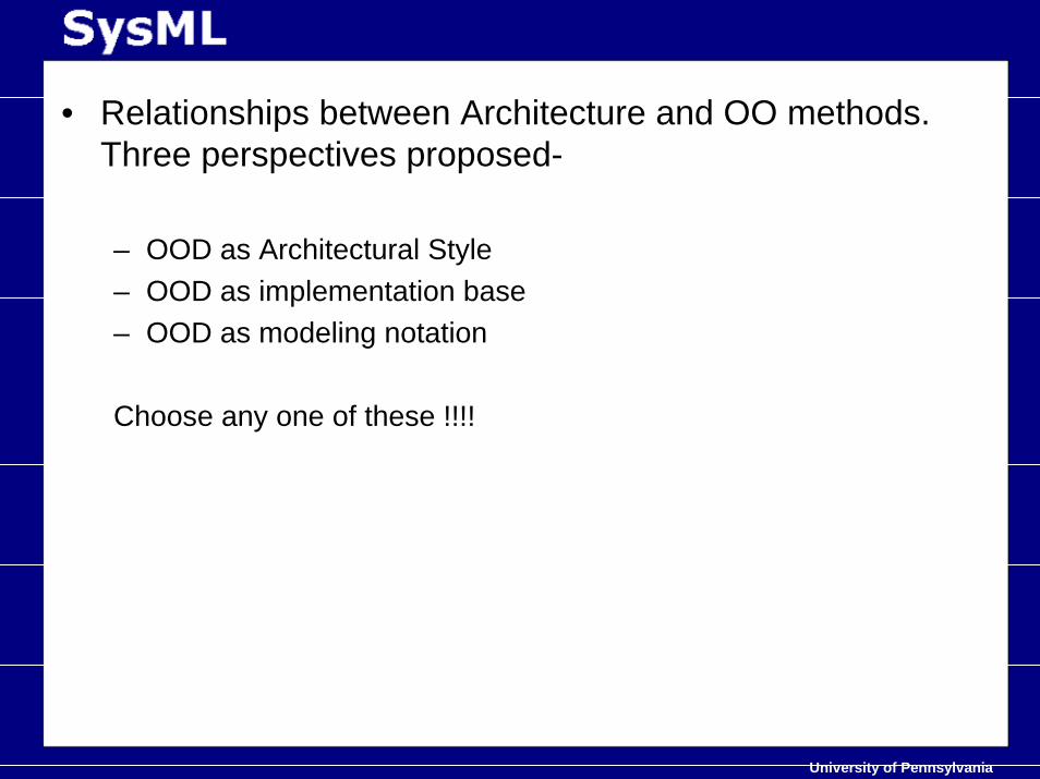
• Relationships between Architecture and OO methods. Three perspectives proposed-
– OOD as Architectural Style – OOD as implementation base– OOD as modeling notation
Choose any one of these !!!!
University of Pennsylvania
• Abstract view on things• Modeling Requirement of RT Systems• OMG’ s MDA• UML overview• Finally…. SysML spec.• Is it the anecdote we look for ??• Bibliography• Something different…..
University of Pennsylvania
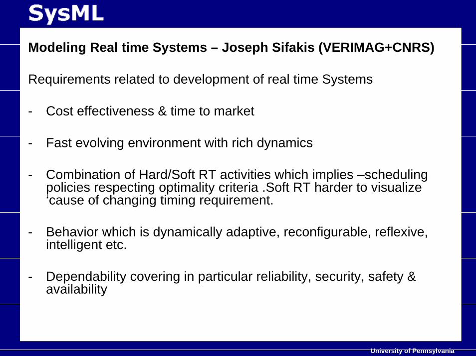
Modeling Real time Systems – Joseph Sifakis (VERIMAG+CNRS)
Requirements related to development of real time Systems
- Cost effectiveness & time to market
- Fast evolving environment with rich dynamics
- Combination of Hard/Soft RT activities which implies –scheduling policies respecting optimality criteria .Soft RT harder to visualize ‘cause of changing timing requirement.
- Behavior which is dynamically adaptive, reconfigurable, reflexive, intelligent etc.
- Dependability covering in particular reliability, security, safety & availability
University of Pennsylvania
Why do we need modeling ….
• Need of unified view of various lifecycle activities and their interdependencies ,motivated model-based approaches, which heavily rely on use of modeling tool & methods to provide support & guidance for development & validation.
University of Pennsylvania
Modeling RT systems
1) Component Based Modeling – models built composing components which are model units fully characterized by their interface.
2) Timed Modeling
University of Pennsylvania
Summary behind the discussion
• A dynamic model of RT system can be realized by adequately restricting the behavior of its application software with timing information
University of Pennsylvania
• Abstract view on things• Modeling Requirement of RT Systems• OMG’ s MDA• UML overview• Finally…. SysML spec.• Case Study• Is it the anecdote we look for ??• Bibliography• Something different…..
University of Pennsylvania
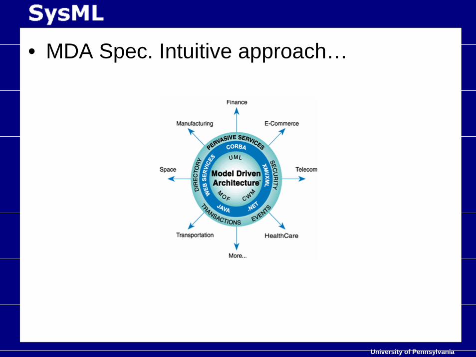
• Model Driven Architecture
Provides an open vendor neutral approach to the challenges of business and technology change. Itseparates business and application logic fromunderlying platform technology.
University of Pennsylvania
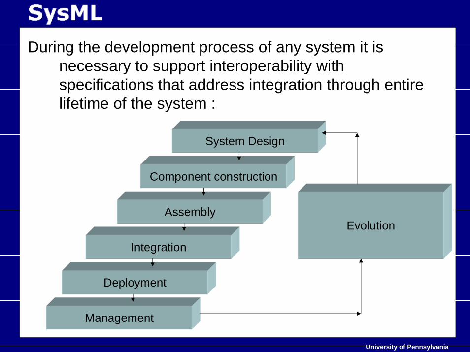
During the development process of any system it is necessary to support interoperability with specifications that address integration through entire lifetime of the system :
Evolution
System Design
Component construction
Assembly
Integration
Deployment
Management
University of Pennsylvania
MDA integrates through –
1) Embracing tech. like CORBA,J2EE,XML,.NET etc.
2) Improving the portability of applications by allowing some model to be realized on multiple platforms through mapping standards.
3) Improving integration based on models of relationships across different domain applications & interfaces allowing interoperability.
University of Pennsylvania
PIM – Platform Independent Models- Provides formal specification of the structure and function of the
system that abstracts away technical details.
- Describes the computational components and their interactions in a platform-independent manner.
Eg. CORBA
PSM – Platform Specific Models - Functionality specified in PIM is realized in platform-specific way in
the PSM.
- Derived from the PIM via some transformation.
Eg RMI stub, skeleton
All OMG stds. are based on this approach of defining systems in termsof PIM and one or more PSM. Eg. UML
University of Pennsylvania
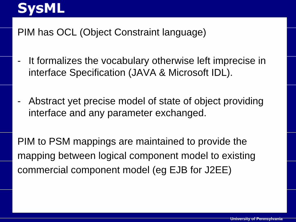
PIM has OCL (Object Constraint language)
- It formalizes the vocabulary otherwise left imprecise in interface Specification (JAVA & Microsoft IDL).
- Abstract yet precise model of state of object providing interface and any parameter exchanged.
PIM to PSM mappings are maintained to provide themapping between logical component model to existingcommercial component model (eg EJB for J2EE)
University of Pennsylvania
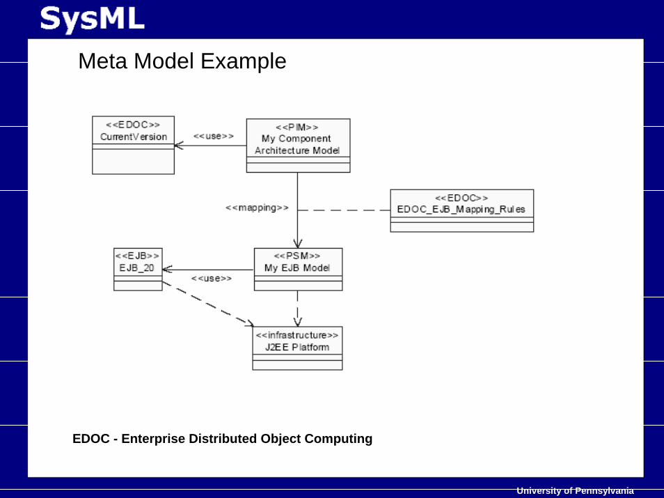
Meta Model Example
EDOC - Enterprise Distributed Object Computing
University of Pennsylvania
• MDA Spec. Intuitive approach…
University of Pennsylvania
• Abstract view on things• Modeling Requirement of RT Systems• OMG’ s MDA• UML overview• Finally…. SysML spec.• Case Study• Is it the anecdote we look for ??• Bibliography• Something different…..
University of Pennsylvania
UML – Unified Modeling Language
The Unified Modeling Language (UML) is astandard language for specifying, visualizing,constructing and documenting the artifacts of softwaresystems, as well as for business modeling and other non-software systems.
The UML represents a collection of best engineeringpractices that have proven successful in the modeling oflarge and complex systems.
University of Pennsylvania
UML – Unified Modeling Language
Historical stuff –
• Development of UML began in late 1994 when Grady Booch and Jim Rumbaugh of Rational Software Corporation began their work on unifying the Booch and OMT (Object Modeling Technique) methods.
• In the Fall of 1995, Ivar Jacobson and his Objectory company joined Rational and this unification effort, merging in the OOSE(Object-Oriented Software Engineering) method.
• As the primary authors of the Booch, OMT, and OOSE methods, Grady Booch, Jim Rumbaugh, and Ivar Jacobson were motivated to create a unified modeling language as all were working on common things.
University of Pennsylvania
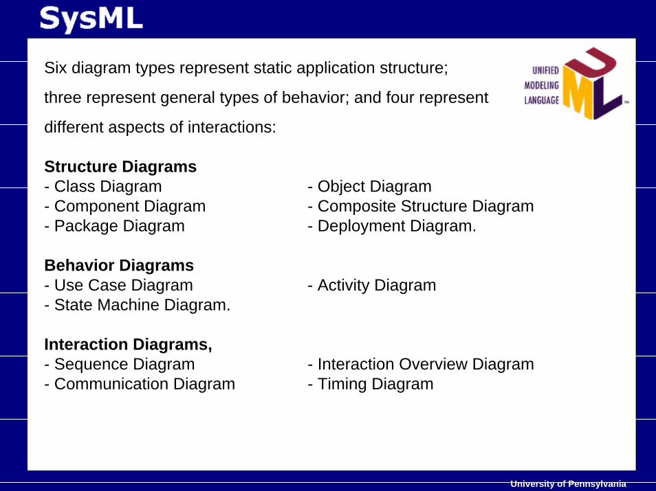
Six diagram types represent static application structure;
three represent general types of behavior; and four represent
different aspects of interactions:
Structure Diagrams- Class Diagram - Object Diagram- Component Diagram - Composite Structure Diagram- Package Diagram - Deployment Diagram.
Behavior Diagrams- Use Case Diagram - Activity Diagram- State Machine Diagram.
Interaction Diagrams,- Sequence Diagram - Interaction Overview Diagram - Communication Diagram - Timing Diagram
University of Pennsylvania
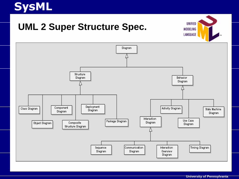
UML 2 Super Structure Spec.
University of Pennsylvania
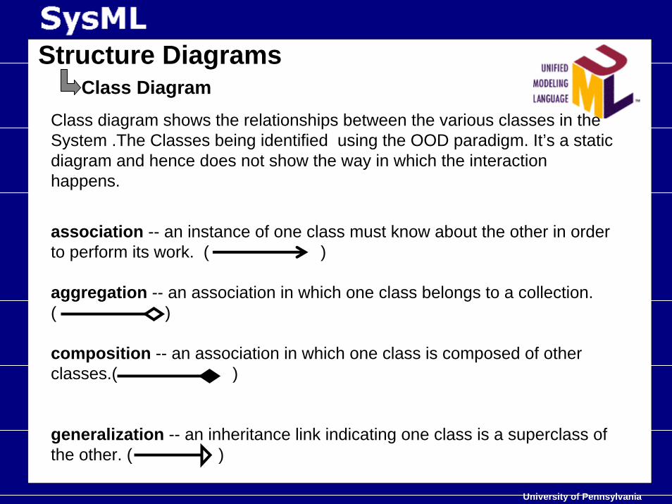
Structure DiagramsClass Diagram
Class diagram shows the relationships between the various classes in the System .The Classes being identified using the OOD paradigm. It’s a static diagram and hence does not show the way in which the interactionhappens.
association -- an instance of one class must know about the other in order to perform its work. ( )
aggregation -- an association in which one class belongs to a collection. ( )
composition -- an association in which one class is composed of other classes.( )
generalization -- an inheritance link indicating one class is a superclass of the other. ( )
University of Pennsylvania
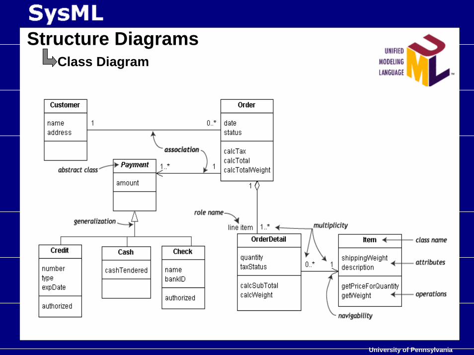
Structure DiagramsClass Diagram
University of Pennsylvania
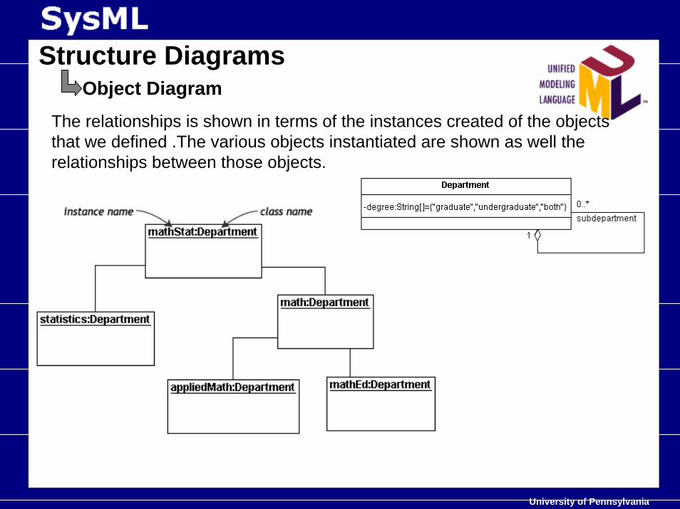
Structure DiagramsObject Diagram
The relationships is shown in terms of the instances created of the objects that we defined .The various objects instantiated are shown as well the relationships between those objects.
University of Pennsylvania
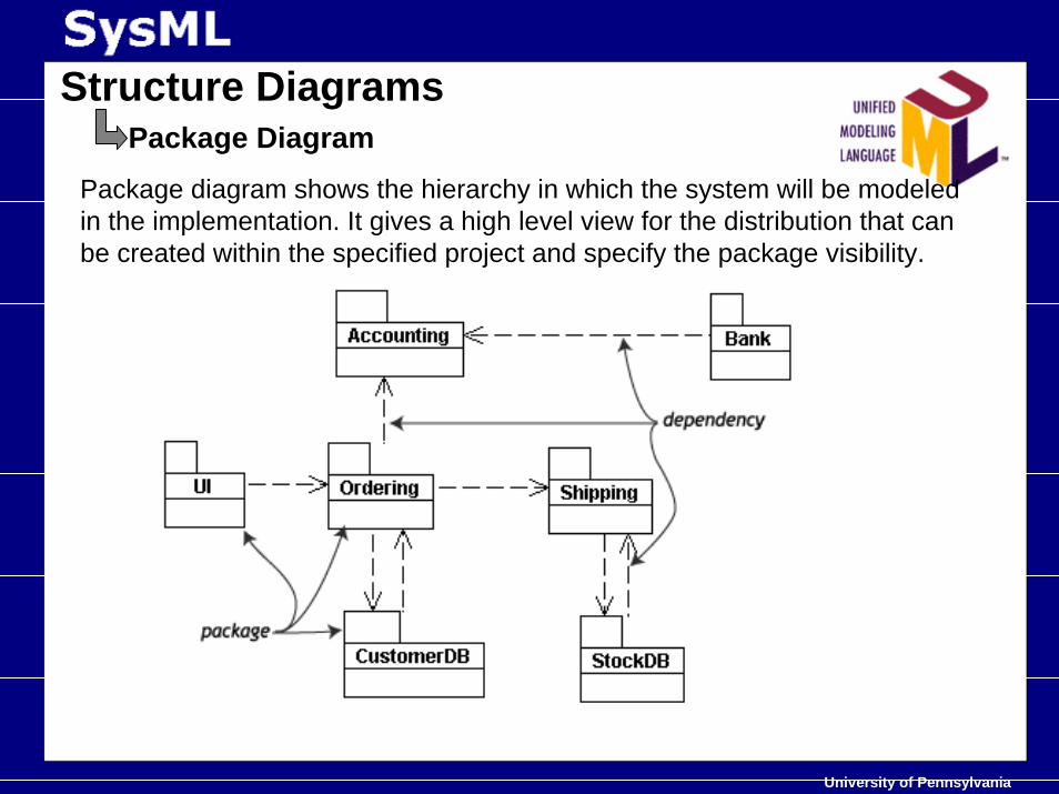
Structure DiagramsPackage Diagram
Package diagram shows the hierarchy in which the system will be modeled in the implementation. It gives a high level view for the distribution that can be created within the specified project and specify the package visibility.
University of Pennsylvania
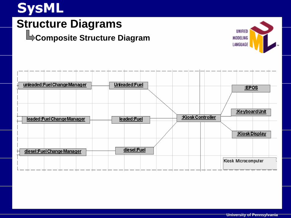
Structure DiagramsComposite Structure Diagram
- Composite Structure diagram reflects the internal collaboration of classes, interfaces or components to describe a functionality.
- Composite Structure diagrams are similar to Class diagrams, except thatthey model a specific usage of the structure.
- Composite Structure diagram is used to express run-time architectures,usage patterns, and the participating elements' relationships,which might not be reflected by static diagrams.
University of Pennsylvania
Structure DiagramsComposite Structure Diagram
University of Pennsylvania
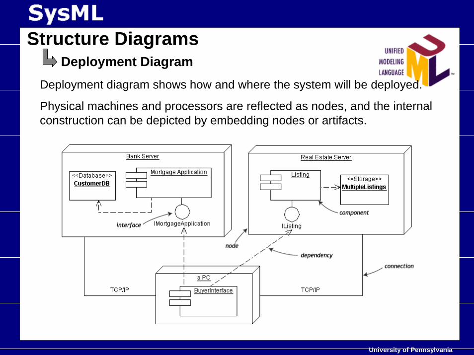
Structure DiagramsDeployment Diagram
Deployment diagram shows how and where the system will be deployed.
Physical machines and processors are reflected as nodes, and the internal construction can be depicted by embedding nodes or artifacts.
University of Pennsylvania
Structure DiagramsComponent Diagram
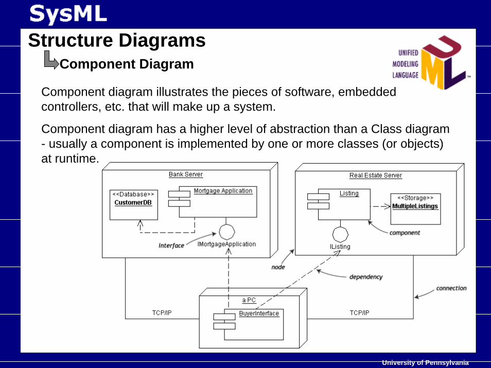
Component diagram illustrates the pieces of software, embedded controllers, etc. that will make up a system.
Component diagram has a higher level of abstraction than a Class diagram - usually a component is implemented by one or more classes (or objects) at runtime.
University of Pennsylvania
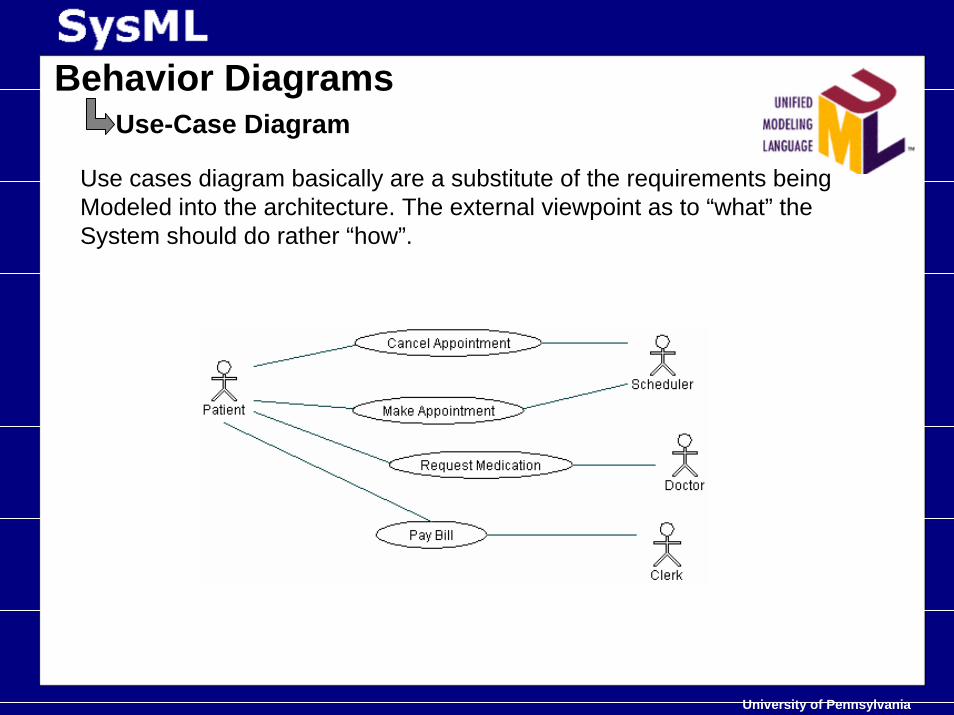
Behavior DiagramsUse-Case Diagram
Use cases diagram basically are a substitute of the requirements being Modeled into the architecture. The external viewpoint as to “what” the System should do rather “how”.
University of Pennsylvania
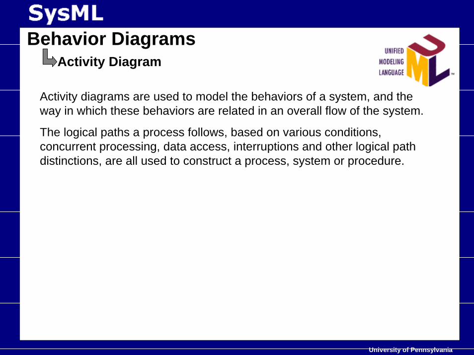
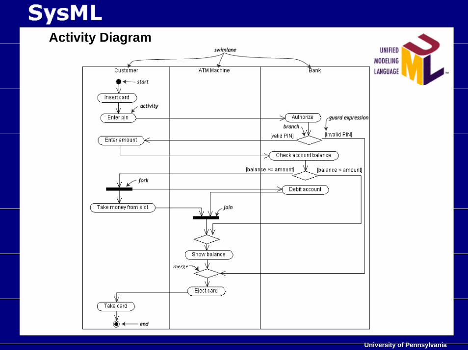
Behavior DiagramsActivity Diagram
Activity diagrams are used to model the behaviors of a system, and the way in which these behaviors are related in an overall flow of the system.
The logical paths a process follows, based on various conditions, concurrent processing, data access, interruptions and other logical path distinctions, are all used to construct a process, system or procedure.
University of Pennsylvania
Activity Diagram
University of Pennsylvania
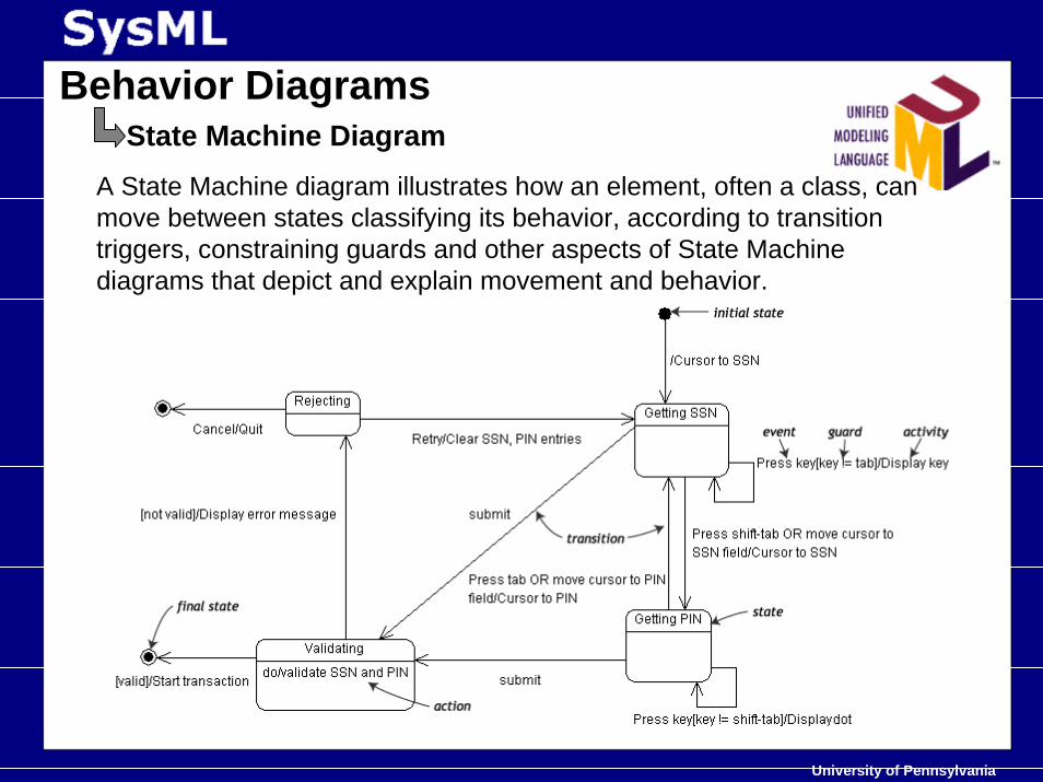
Behavior DiagramsState Machine Diagram
A State Machine diagram illustrates how an element, often a class, can move between states classifying its behavior, according to transition triggers, constraining guards and other aspects of State Machinediagrams that depict and explain movement and behavior.
University of Pennsylvania
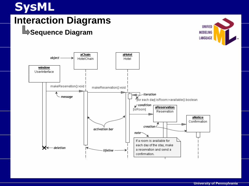
Interaction DiagramsSequence Diagram
Sequence diagram is an interaction diagram that details how operations are carried out -- what messages are sent and when.
Sequence diagrams are organized according to time expressed in the sequential order along the vertical plane.
University of Pennsylvania
Interaction DiagramsSequence Diagram
University of Pennsylvania
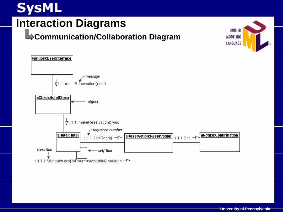
Interaction DiagramsCommunication/Collaboration Diagram
Communication diagram shows the interactions between elements at run-time in much the same manner as a Sequence diagram.
Communication diagrams are used to visualize inter-object relationships, while Sequence diagrams are more effective at visualizing processing over time.
University of Pennsylvania
Interaction DiagramsCommunication/Collaboration Diagram
University of Pennsylvania
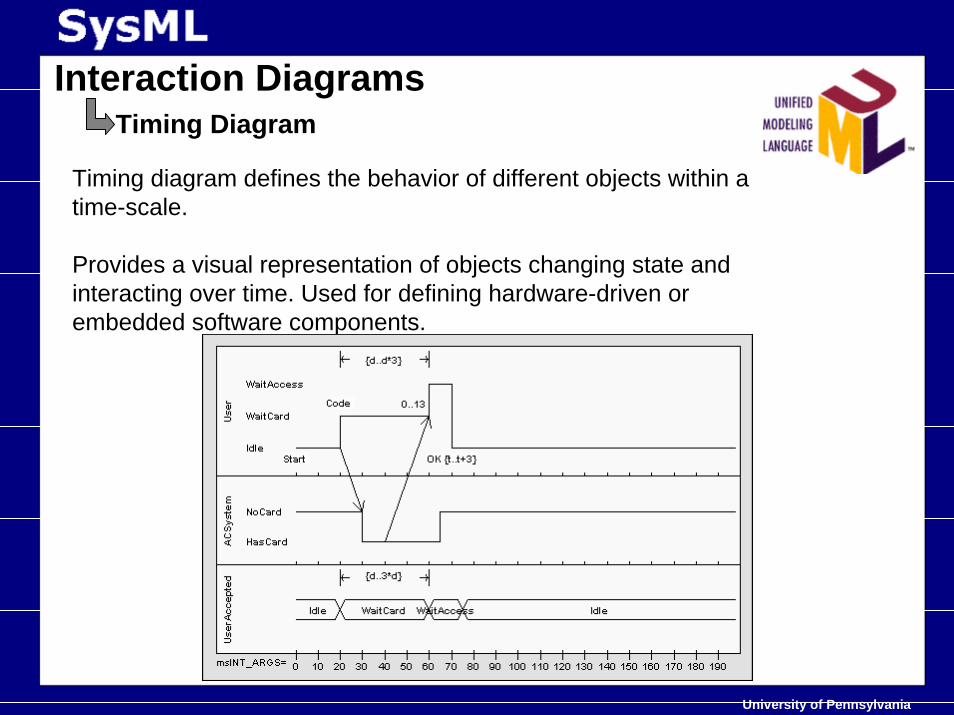
Interaction DiagramsTiming Diagram
Timing diagram defines the behavior of different objects within a time-scale.
Provides a visual representation of objects changing state and interacting over time. Used for defining hardware-driven or embedded software components.
University of Pennsylvania
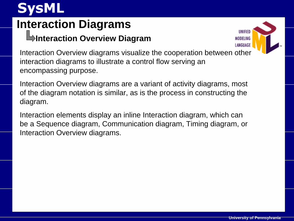
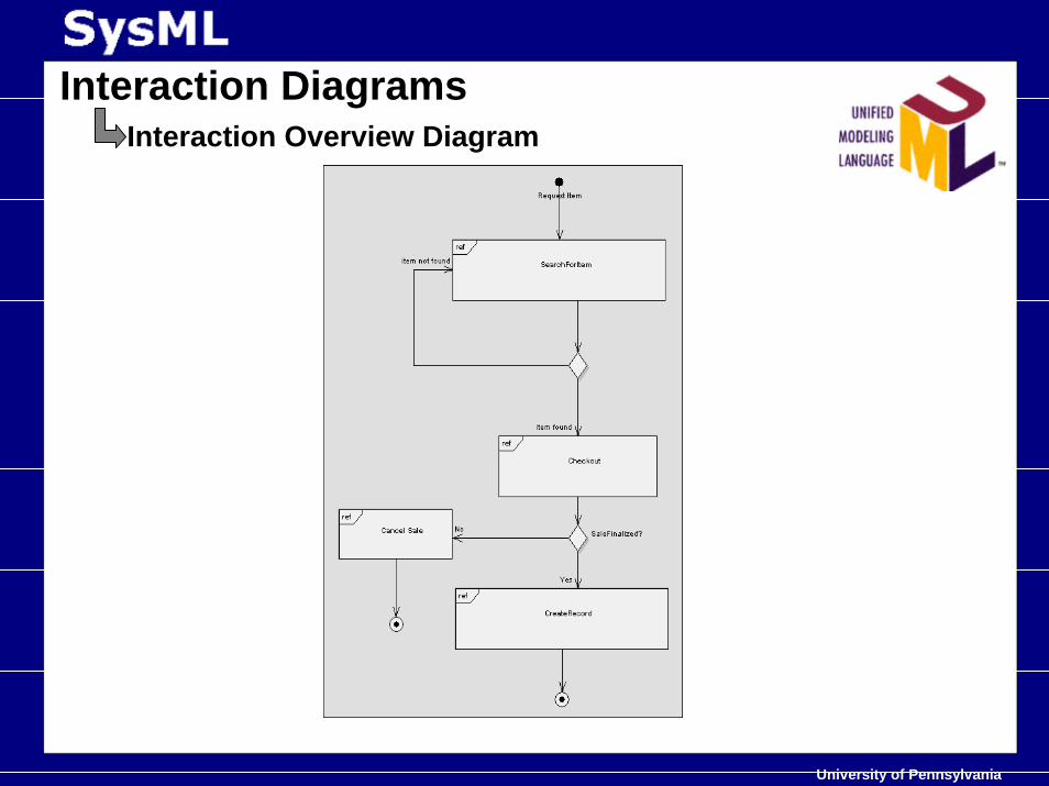
Interaction DiagramsInteraction Overview Diagram
Interaction Overview diagrams visualize the cooperation between other interaction diagrams to illustrate a control flow serving an encompassing purpose.
Interaction Overview diagrams are a variant of activity diagrams, most of the diagram notation is similar, as is the process in constructing the diagram.
Interaction elements display an inline Interaction diagram, which can be a Sequence diagram, Communication diagram, Timing diagram, orInteraction Overview diagrams.
University of Pennsylvania
Interaction DiagramsInteraction Overview Diagram
University of Pennsylvania
RTUML- RT flavor to UML
UML was customized under one of the RFP to “define thestandard paradigms for modeling of time- ,schedule - and performance-related aspects of RT systems”.
University of Pennsylvania
• Abstract view on things• Modeling Requirement of RT Systems• OMG’ s MDA• UML overview• Finally…. SysML spec.• Case Study• Is it the anecdote we look for ??• Bibliography• Something different…..
University of Pennsylvania
SysML was identified as the key modeling language thatcould integrate the disparate tools sets that SE’s use for asingle project across various domains .
The idea behind it was that it would do the same trick forthe Systems Engineering field as UML did for the loads ofmodeling languages in Software.
Short Comings….hold till the end.
University of Pennsylvania
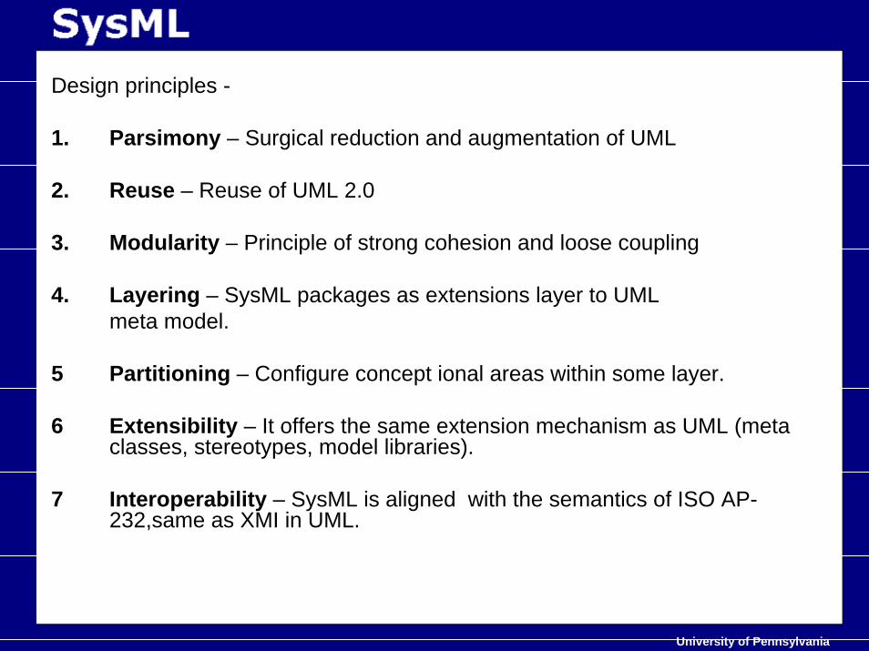
Design principles -
1. Parsimony – Surgical reduction and augmentation of UML
2. Reuse – Reuse of UML 2.0
3. Modularity – Principle of strong cohesion and loose coupling
4. Layering – SysML packages as extensions layer to UMLmeta model.
5 Partitioning – Configure concept ional areas within some layer.
6 Extensibility – It offers the same extension mechanism as UML (meta classes, stereotypes, model libraries).
7 Interoperability – SysML is aligned with the semantics of ISO AP-232,same as XMI in UML.
University of Pennsylvania
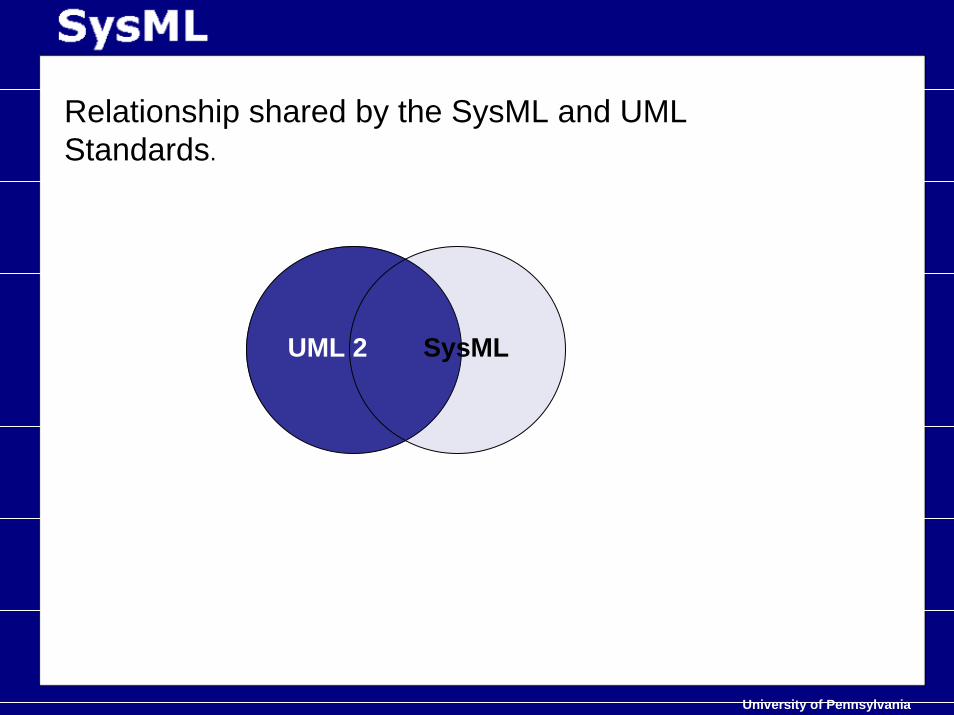
Relationship shared by the SysML and UML Standards.
UML 2 SysML
University of Pennsylvania
Architecture
SysML reuses and extends packages from UML, extensionMechanisms like stereotypes, meta classes and modellibraries.
Structure still remains the same for the Constructs .
It uses combination of profiling and meta modelingtechniques that use precise language to specifyconstraints and semantics.
University of Pennsylvania
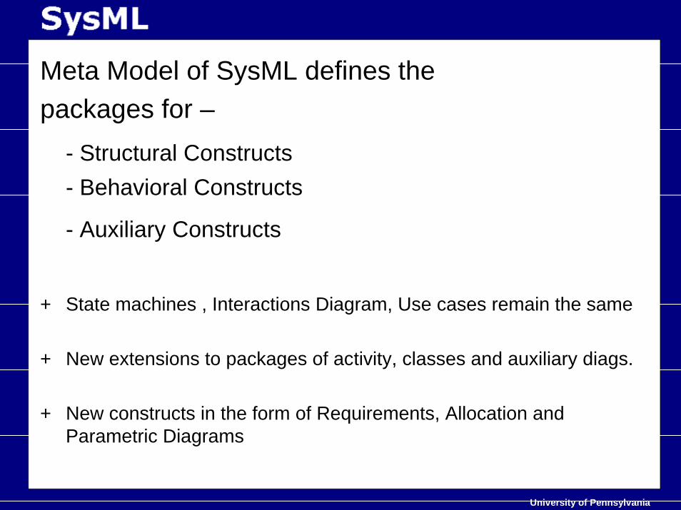
Meta Model of SysML defines the packages for –
- Structural Constructs - Behavioral Constructs
- Auxiliary Constructs
+ State machines , Interactions Diagram, Use cases remain the same
+ New extensions to packages of activity, classes and auxiliary diags.
+ New constructs in the form of Requirements, Allocation and Parametric Diagrams
University of Pennsylvania
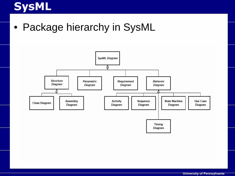
• Package hierarchy in SysML
University of Pennsylvania
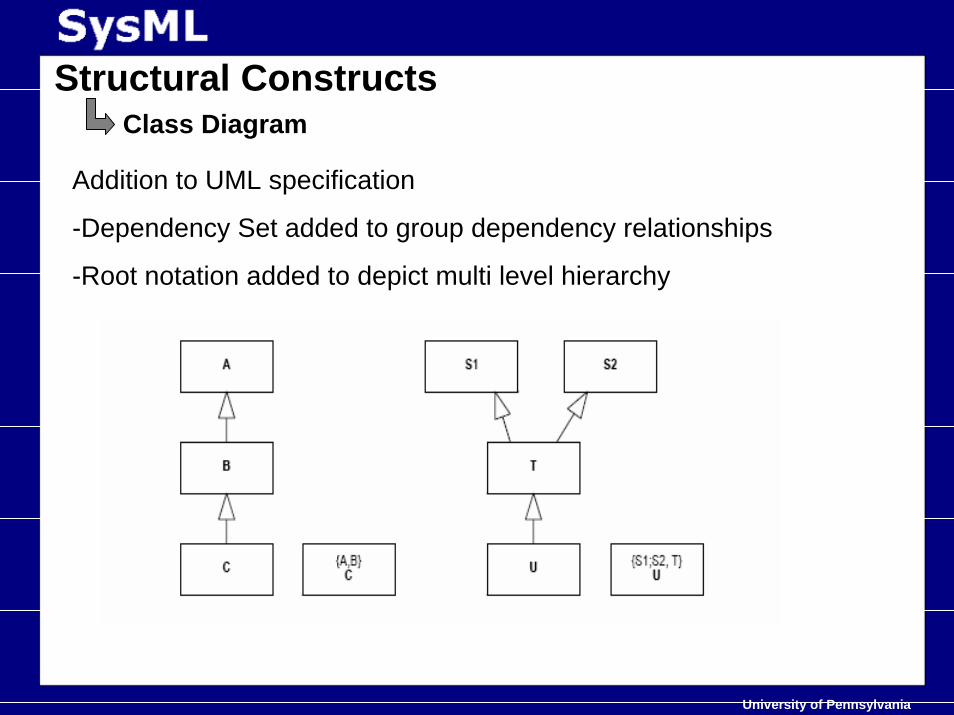
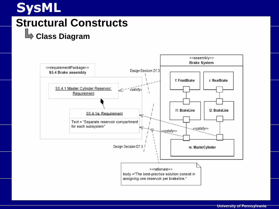
Structural ConstructsClass Diagram
Addition to UML specification
-Dependency Set added to group dependency relationships
-Root notation added to depict multi level hierarchy
University of Pennsylvania
Structural ConstructsClass Diagram
University of Pennsylvania
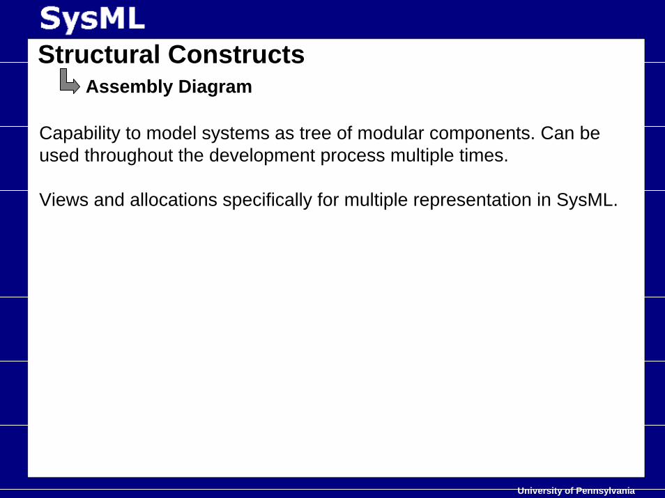
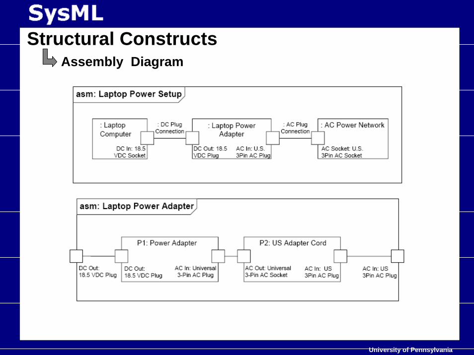
Structural ConstructsAssembly Diagram
Capability to model systems as tree of modular components. Can beused throughout the development process multiple times.
Views and allocations specifically for multiple representation in SysML.
University of Pennsylvania
Structural ConstructsAssembly Diagram
University of Pennsylvania
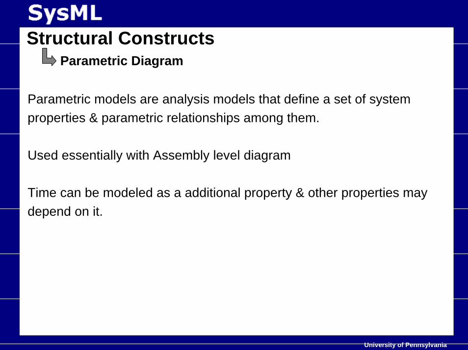
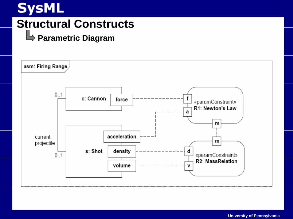
Structural ConstructsParametric Diagram
Parametric models are analysis models that define a set of systemproperties & parametric relationships among them.
Used essentially with Assembly level diagram
Time can be modeled as a additional property & other properties maydepend on it.
University of Pennsylvania
Structural ConstructsParametric Diagram
University of Pennsylvania
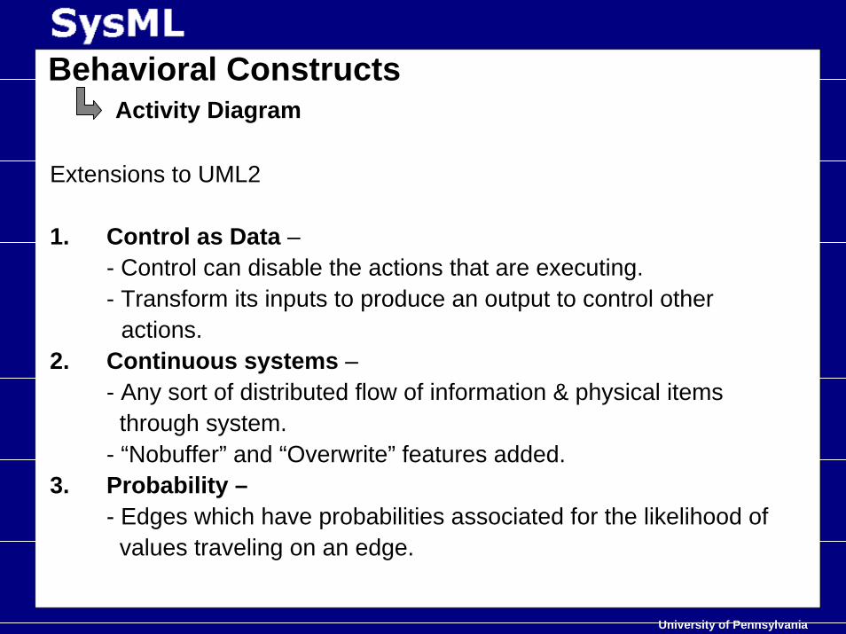
Behavioral ConstructsActivity Diagram
Extensions to UML2
1. Control as Data –- Control can disable the actions that are executing. - Transform its inputs to produce an output to control other
actions.2. Continuous systems –
- Any sort of distributed flow of information & physical itemsthrough system.
- “Nobuffer” and “Overwrite” features added.3. Probability –
- Edges which have probabilities associated for the likelihood ofvalues traveling on an edge.
University of Pennsylvania
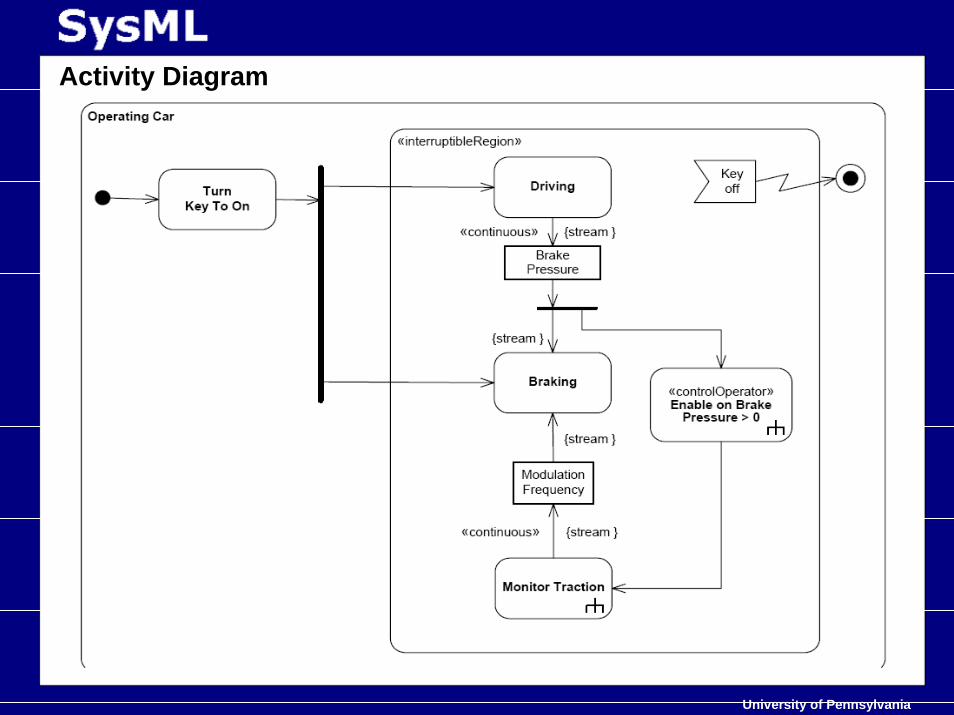
Activity Diagram
University of Pennsylvania
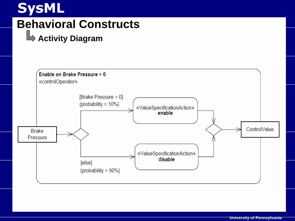
Behavioral ConstructsActivity Diagram
University of Pennsylvania
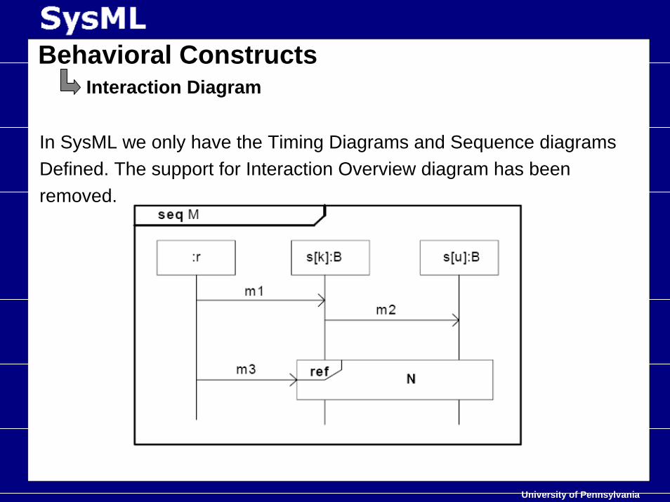
In SysML we only have the Timing Diagrams and Sequence diagramsDefined. The support for Interaction Overview diagram has beenremoved.
Behavioral ConstructsInteraction Diagram
University of Pennsylvania
Behavioral ConstructsTiming Diagram
Same as UML standard .No additions have been made to the Timing Diagram.
University of Pennsylvania
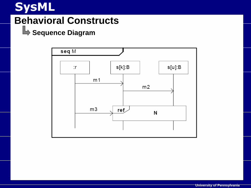
Behavioral ConstructsSequence Diagram
University of Pennsylvania
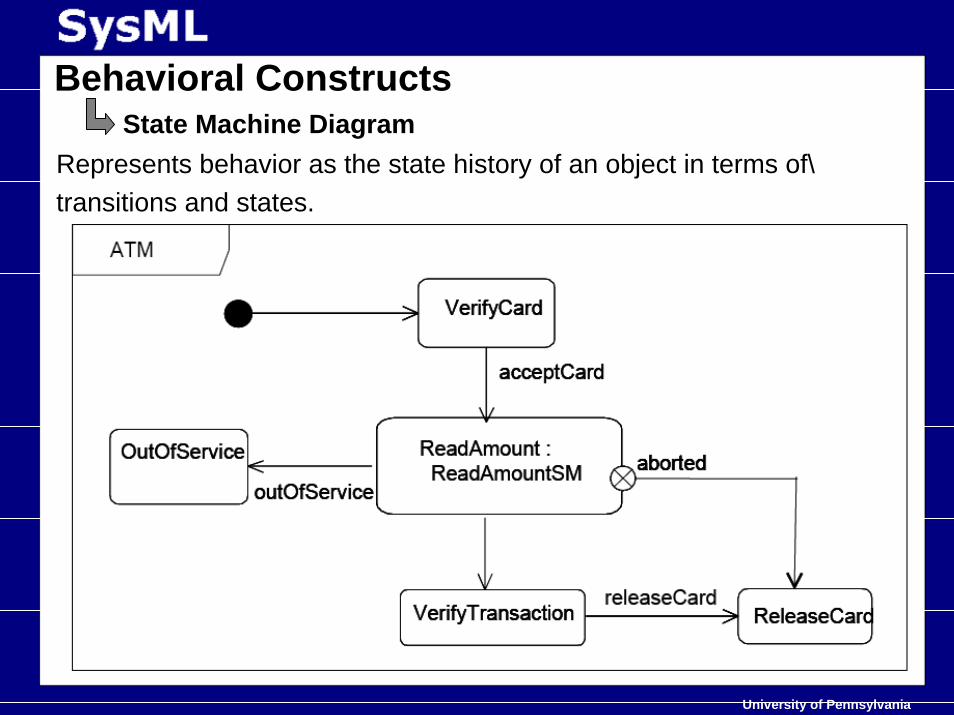
Represents behavior as the state history of an object in terms of\transitions and states.
Behavioral ConstructsState Machine Diagram
University of Pennsylvania
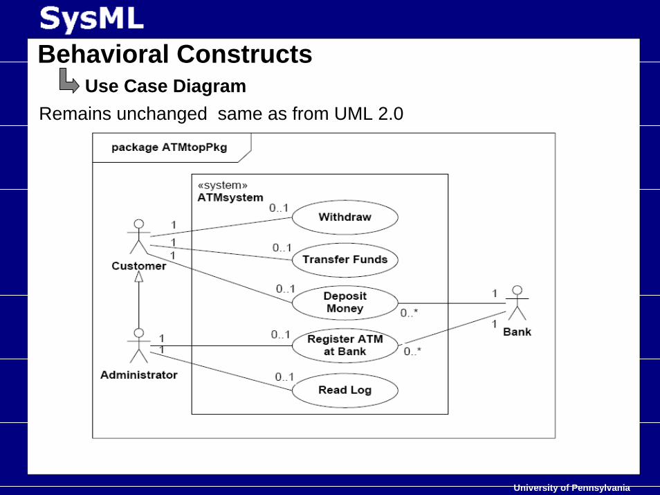
Remains unchanged same as from UML 2.0
Behavioral ConstructsUse Case Diagram
University of Pennsylvania
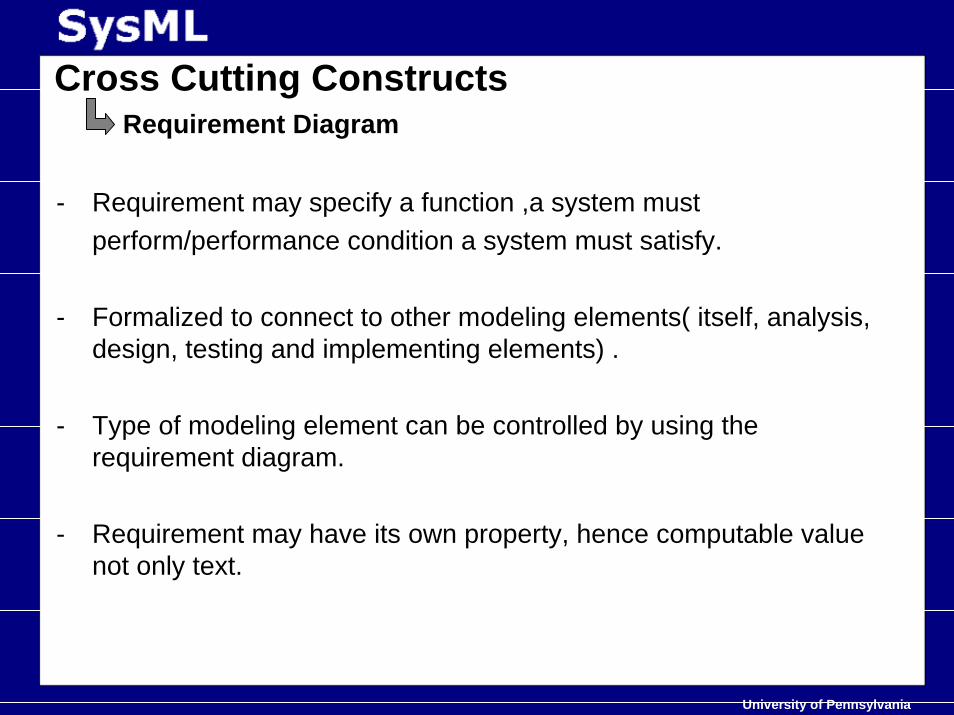
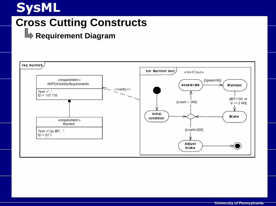
Cross Cutting ConstructsRequirement Diagram
- Requirement may specify a function ,a system mustperform/performance condition a system must satisfy.
- Formalized to connect to other modeling elements( itself, analysis, design, testing and implementing elements) .
- Type of modeling element can be controlled by using the requirement diagram.
- Requirement may have its own property, hence computable value not only text.
University of Pennsylvania
Cross Cutting ConstructsRequirement Diagram
University of Pennsylvania
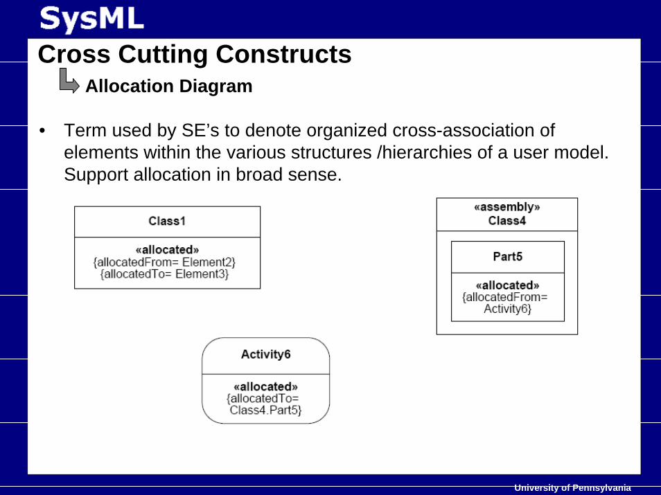
Cross Cutting ConstructsAllocation Diagram
• Term used by SE’s to denote organized cross-association of elements within the various structures /hierarchies of a user model. Support allocation in broad sense.
University of Pennsylvania
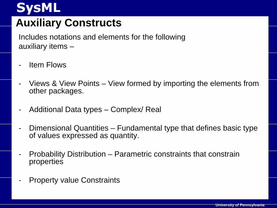
Auxiliary ConstructsIncludes notations and elements for the following auxiliary items –
- Item Flows
- Views & View Points – View formed by importing the elements from other packages.
- Additional Data types – Complex/ Real
- Dimensional Quantities – Fundamental type that defines basic type of values expressed as quantity.
- Probability Distribution – Parametric constraints that constrain properties
- Property value Constraints
University of Pennsylvania
• Abstract view on things• Modeling Requirement of RT Systems• OMG’ s MDA• UML overview• Finally…. SysML spec.• Case Study• Is it the anecdote we look for ??• Bibliography• Something different…..
University of Pennsylvania
• Abstract view on things• Modeling Requirement of RT Systems• OMG’ s MDA• UML overview• Finally…. SysML spec.• Case Study• Is it the anecdote we look for ??• Bibliography• Something different…..
University of Pennsylvania
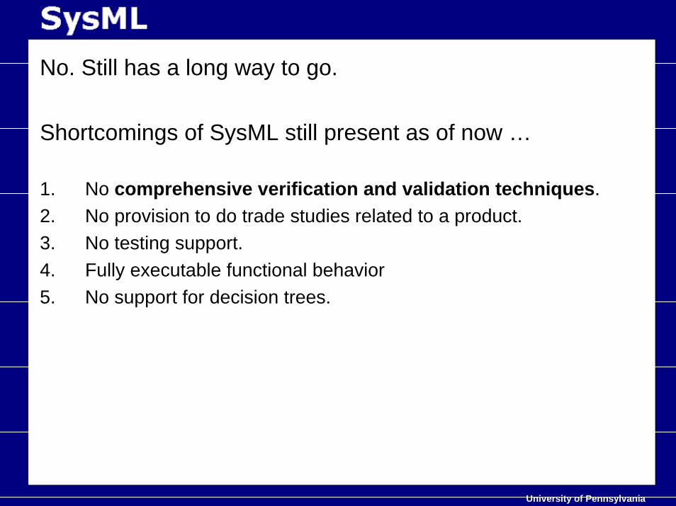
No. Still has a long way to go.
Shortcomings of SysML still present as of now …
1. No comprehensive verification and validation techniques.2. No provision to do trade studies related to a product.3. No testing support.4. Fully executable functional behavior5. No support for decision trees.
University of Pennsylvania
• Abstract view on things• Modeling Requirement of RT Systems• OMG’ s MDA• UML overview• Finally…. SysML spec.• Case Study• Is it the anecdote we look for ??• Bibliography• Something different…..
University of Pennsylvania
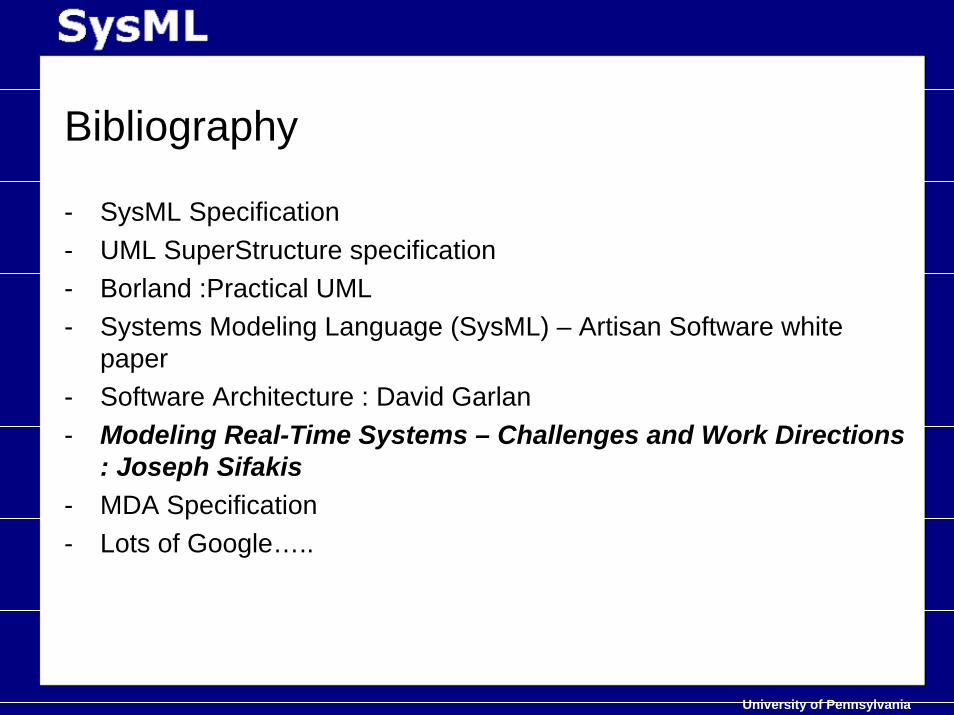
Bibliography
- SysML Specification- UML SuperStructure specification - Borland :Practical UML - Systems Modeling Language (SysML) – Artisan Software white
paper- Software Architecture : David Garlan- Modeling Real-Time Systems – Challenges and Work Directions
: Joseph Sifakis- MDA Specification- Lots of Google…..
University of Pennsylvania
• Abstract view on things• Modeling Requirement of RT Systems• OMG’ s MDA• UML overview• Finally…. SysML spec.• Case Study• Is it the anecdote we look for ??• Still to come ……• Bibliography• Something different…..

University of Pennsylvania